Embed Size (px)
Citation preview
776 A Textbook of Machine Design
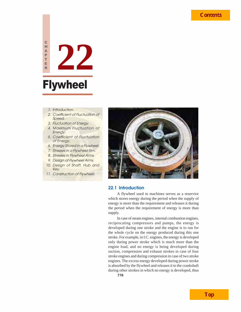
Flywheel
776
1. Introduction.2. Coefficient of Fluctuation of
Speed.3. Fluctuation of Energy.4. Maximum Fluctuation of
Energy.5. Coefficient of Fluctuation
of Energy.6. Energy Stored in a Flywheel.7. Stresses in a Flywheel Rim.8. Stresses in Flywheel Arms.9. Design of Flywheel Arms.
10. Design of Shaft, Hub andKey.
11. Construction of Flywheel.
22CHAPTER
22.1 IntroductionA flywheel used in machines serves as a reservior
which stores energy during the period when the supply ofenergy is more than the requirement and releases it duringthe period when the requirement of energy is more thansupply.
In case of steam engines, internal combustion engines,reciprocating compressors and pumps, the energy isdeveloped during one stroke and the engine is to run forthe whole cycle on the energy produced during this onestroke. For example, in I.C. engines, the energy is developedonly during power stroke which is much more than theengine load, and no energy is being developed duringsuction, compression and exhaust strokes in case of fourstroke engines and during compression in case of two strokeengines. The excess energy developed during power strokeis absorbed by the flywheel and releases it to the crankshaftduring other strokes in which no energy is developed, thus
Flywheel 777rotating the crankshaft at a uniform speed. A little consideration will show that when the flywheelabsorbs energy, its speed increases and when it releases, the speed decreases. Hence a flywheel doesnot maintain a constant speed, it simply reduces the fluctuation of speed.
In machines where the operation is intermittent like punching machines, shearing machines,riveting machines, crushers etc., the flywheel stores energy from the power source during the greaterportion of the operating cycle and gives it up during a small period of the cycle. Thus the energy fromthe power source to the machines is supplied practically at a constant rate throughout the operation.
Note: The function of a governor in engineis entirely different from that of a flywheel.It regulates the mean speed of an enginewhen there are variations in the load, e.g.when the load on the engine increases, itbecomes necessary to increase the supply ofworking fluid. On the other hand, when theload decreases, less working fluid is required.The governor automatically controls thesupply of working fluid to the engine withthe varying load condition and keeps themean speed within certain limits.
As discussed above, the flywheel doesnot maintain a constant speed, it simplyreduces the fluctuation of speed. In otherwords, a flywheel controls the speed variations caused by the fluctuation of the engine turning moment duringeach cycle of operation. It does not control the speed variations caused by the varying load.
22.2 Coefficient of Fluctuation of SpeedThe difference between the maximum and minimum speeds during a cycle is called the maximum
fluctuation of speed. The ratio of the maximum fluctuation of speed to the mean speed is calledcoefficient of fluctuation of speed.
Let N1 = Maximum speed in r.p.m. during the cycle,
N2 = Minimum speed in r.p.m. during the cycle, and
N = Mean speed in r.p.m. = 1 2
2+N N
∴ Coefficient of fluctuation of speed,
CS = ( )1 21 2
1 2
2 N NN NN N N
−− =+
= ( )1 21 2
1 2
2 ω − ωω − ω =ω ω + ω
...(In terms of angular speeds)
= ( )1 21 2
1 2
2 v vv vv v v
−− =+
...(In terms of linear speeds)
The coefficient of fluctuation of speed is a limiting factor in the design of flywheel. It variesdepending upon the nature of service to which the flywheel is employed. Table 22.1 shows the per-missible values for coefficient of fluctuation of speed for some machines.
Note: The reciprocal of coefficient of fluctuation of speed is known as coefficient of steadiness and it is de-noted by m.
∴ m = S 1 2 1 2 1 2
1 ω= = =− ω − ω −N v
C N N v v
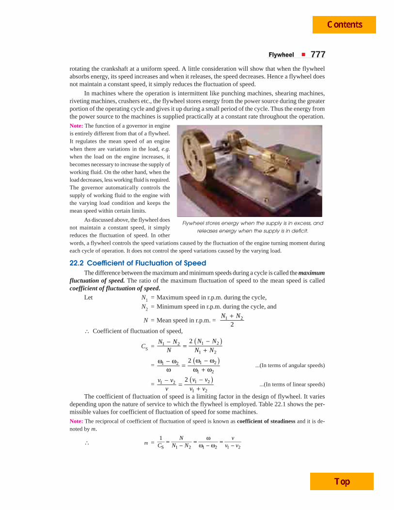
Flywheel stores energy when the supply is in excess, and
releases energy when the supply is in deficit.
778 A Textbook of Machine Design
Table 22.1. Permissible values for coefficient of fluctuation of speed (CS).
S.No. Type of machine or class of service Coefficient of fluctuation of speed (CS)
1. Crushing machines 0.200
2. Electrical machines 0.003
3. Electrical machines (direct drive) 0.002
4. Engines with belt transmission 0.030
5. Gear wheel transmission 0.020
6. Hammering machines 0.200
7. Pumping machines 0.03 to 0.05
8. Machine tools 0.030
9. Paper making, textile and weaving machines 0.025
10. Punching, shearing and power presses 0.10 to 0.15
11. Spinning machinery 0.10 to 0.020
12. Rolling mills and mining machines 0.025
22.3 Fluctuation of EnergyThe fluctuation of energy may be determined by the turning moment diagram for one complete
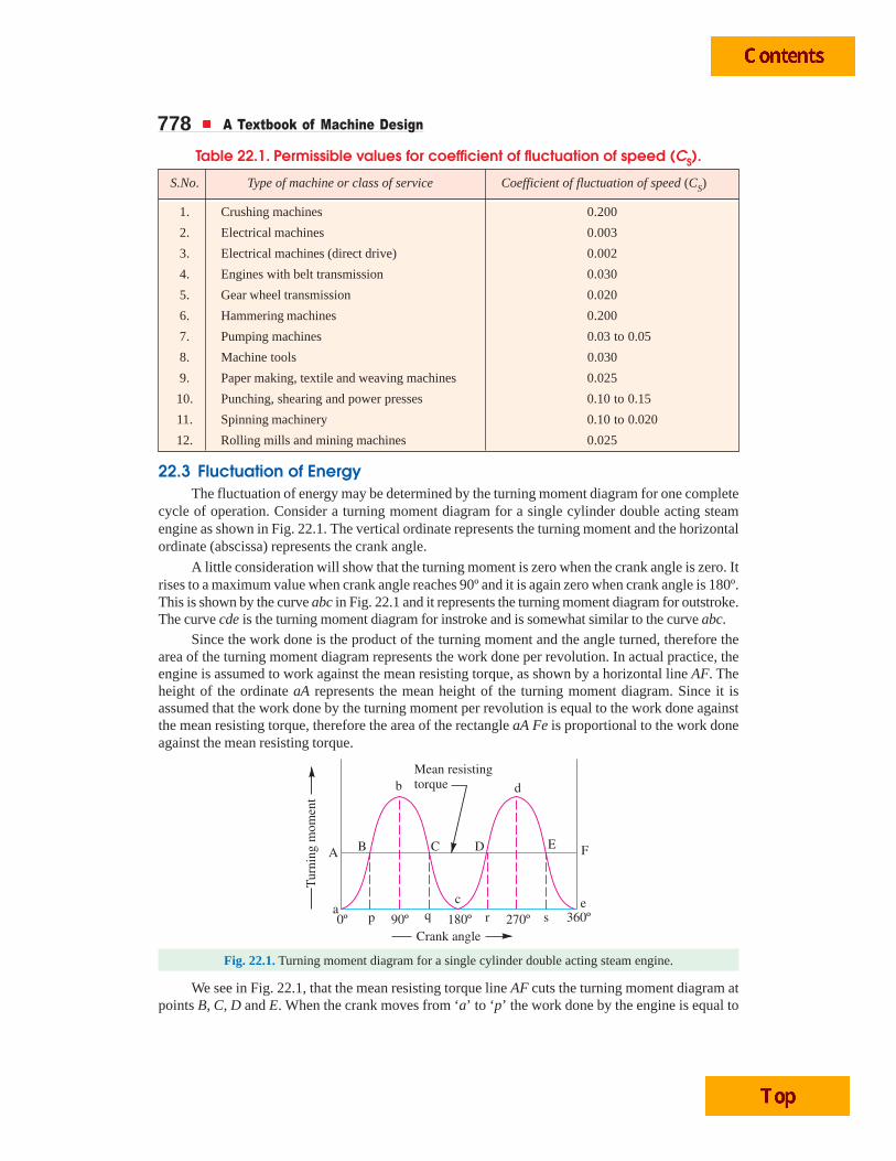
cycle of operation. Consider a turning moment diagram for a single cylinder double acting steamengine as shown in Fig. 22.1. The vertical ordinate represents the turning moment and the horizontalordinate (abscissa) represents the crank angle.
A little consideration will show that the turning moment is zero when the crank angle is zero. Itrises to a maximum value when crank angle reaches 90º and it is again zero when crank angle is 180º.This is shown by the curve abc in Fig. 22.1 and it represents the turning moment diagram for outstroke.The curve cde is the turning moment diagram for instroke and is somewhat similar to the curve abc.
Since the work done is the product of the turning moment and the angle turned, therefore thearea of the turning moment diagram represents the work done per revolution. In actual practice, theengine is assumed to work against the mean resisting torque, as shown by a horizontal line AF. Theheight of the ordinate aA represents the mean height of the turning moment diagram. Since it isassumed that the work done by the turning moment per revolution is equal to the work done againstthe mean resisting torque, therefore the area of the rectangle aA Fe is proportional to the work doneagainst the mean resisting torque.
Fig. 22.1. Turning moment diagram for a single cylinder double acting steam engine.
We see in Fig. 22.1, that the mean resisting torque line AF cuts the turning moment diagram atpoints B, C, D and E. When the crank moves from ‘a’ to ‘p’ the work done by the engine is equal to
Flywheel 779the area aBp, whereas the energy required is represented by the area aABp. In other words, the enginehas done less work (equal to the area aAB) than the requirement. This amount of energy is taken fromthe flywheel and hence the speed of the flywheel decreases. Now the crank moves from p to q, thework done by the engine is equal to the area pBbCq, whereas the requirement of energy is representedby the area pBCq. Therefore the engine has done more work than the requirement. This excess work(equal to the area BbC) is stored in the flywheel and hence the speed of the flywheel increases whilethe crank moves from p to q.
Similarly when the crank moves from q to r, more work is taken from the engine than is developed.This loss of work is represented by the area CcD. To supply this loss, the flywheel gives up some ofits energy and thus the speed decreases while the crank moves from q to r. As the crank moves fromr to s, excess energy is again developed given by the area DdE and the speed again increases. As thepiston moves from s to e, again there is a loss of work and the speed decreases. The variations ofenergy above and below the mean resisting torque line are called fluctuation of energy. The areasBbC, CcD, DdE etc. represent fluctuations of energy.
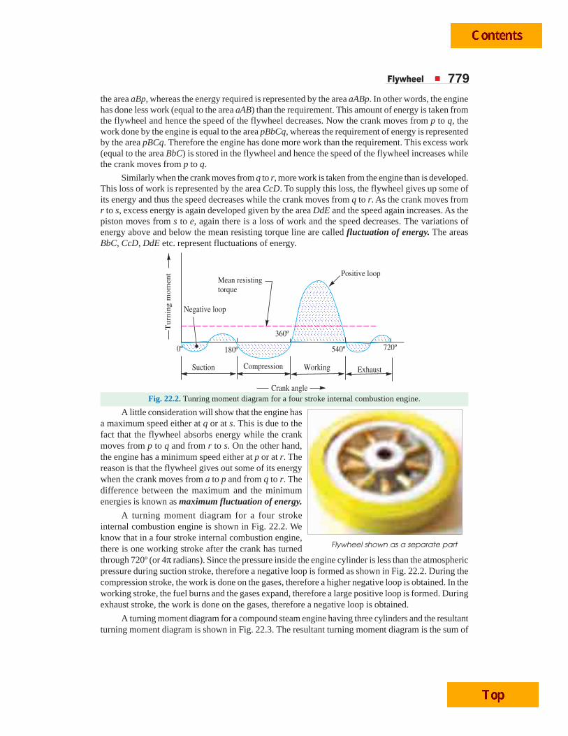
Fig. 22.2. Tunring moment diagram for a four stroke internal combustion engine.
A little consideration will show that the engine hasa maximum speed either at q or at s. This is due to thefact that the flywheel absorbs energy while the crankmoves from p to q and from r to s. On the other hand,the engine has a minimum speed either at p or at r. Thereason is that the flywheel gives out some of its energywhen the crank moves from a to p and from q to r. Thedifference between the maximum and the minimumenergies is known as maximum fluctuation of energy.
A turning moment diagram for a four strokeinternal combustion engine is shown in Fig. 22.2. Weknow that in a four stroke internal combustion engine,there is one working stroke after the crank has turnedthrough 720º (or 4π radians). Since the pressure inside the engine cylinder is less than the atmosphericpressure during suction stroke, therefore a negative loop is formed as shown in Fig. 22.2. During thecompression stroke, the work is done on the gases, therefore a higher negative loop is obtained. In theworking stroke, the fuel burns and the gases expand, therefore a large positive loop is formed. Duringexhaust stroke, the work is done on the gases, therefore a negative loop is obtained.
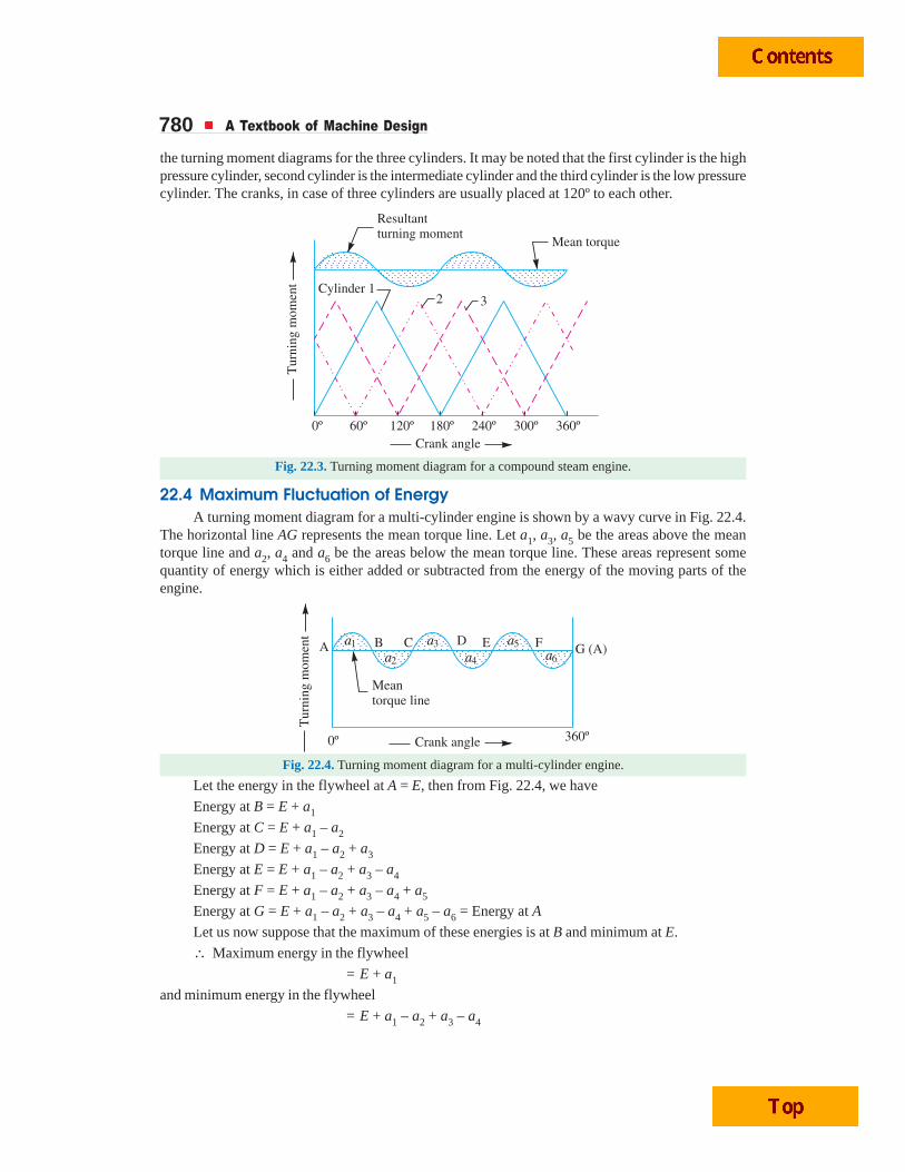
A turning moment diagram for a compound steam engine having three cylinders and the resultantturning moment diagram is shown in Fig. 22.3. The resultant turning moment diagram is the sum of
Flywheel shown as a separate part
780 A Textbook of Machine Design
the turning moment diagrams for the three cylinders. It may be noted that the first cylinder is the highpressure cylinder, second cylinder is the intermediate cylinder and the third cylinder is the low pressurecylinder. The cranks, in case of three cylinders are usually placed at 120º to each other.
Fig. 22.3. Turning moment diagram for a compound steam engine.
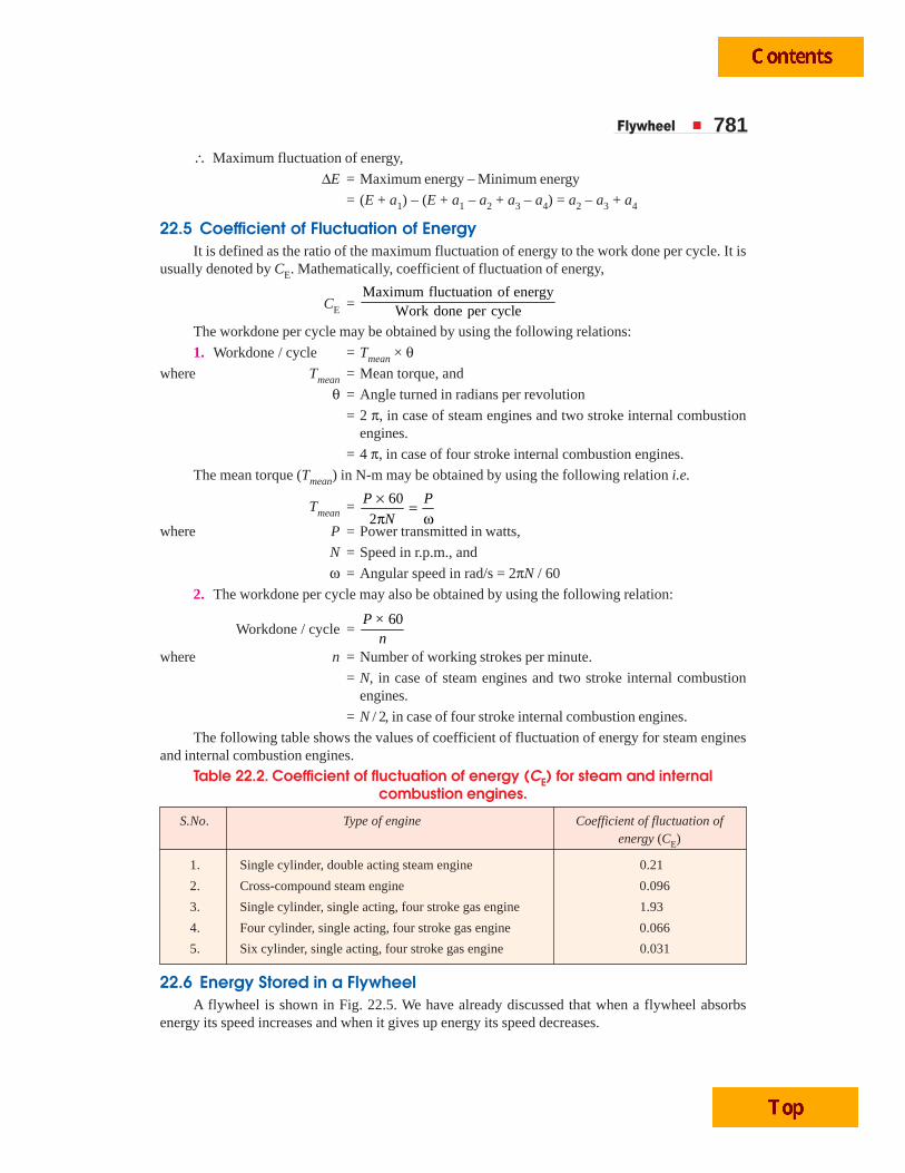
22.4 Maximum Fluctuation of EnergyA turning moment diagram for a multi-cylinder engine is shown by a wavy curve in Fig. 22.4.
The horizontal line AG represents the mean torque line. Let a1, a3, a5 be the areas above the meantorque line and a2, a4 and a6 be the areas below the mean torque line. These areas represent somequantity of energy which is either added or subtracted from the energy of the moving parts of theengine.
Fig. 22.4. Turning moment diagram for a multi-cylinder engine.
Let the energy in the flywheel at A = E, then from Fig. 22.4, we have
Energy at B = E + a1
Energy at C = E + a1 – a2
Energy at D = E + a1 – a2 + a3
Energy at E = E + a1 – a2 + a3 – a4
Energy at F = E + a1 – a2 + a3 – a4 + a5
Energy at G = E + a1 – a2 + a3 – a4 + a5 – a6 = Energy at A
Let us now suppose that the maximum of these energies is at B and minimum at E.
∴ Maximum energy in the flywheel
= E + a1
and minimum energy in the flywheel
= E + a1 – a2 + a3 – a4
Flywheel 781∴ Maximum fluctuation of energy,
ΔE = Maximum energy – Minimum energy
= (E + a1) – (E + a1 – a2 + a3 – a4) = a2 – a3 + a4
22.5 Coefficient of Fluctuation of EnergyIt is defined as the ratio of the maximum fluctuation of energy to the work done per cycle. It is
usually denoted by CE. Mathematically, coefficient of fluctuation of energy,
CE = Maximum fluctuation of energy
Work done per cycle
The workdone per cycle may be obtained by using the following relations:
1. Workdone / cycle = Tmean × θwhere Tmean = Mean torque, and
θ = Angle turned in radians per revolution
= 2 π, in case of steam engines and two stroke internal combustionengines.
= 4 π, in case of four stroke internal combustion engines.
The mean torque (Tmean) in N-m may be obtained by using the following relation i.e.
Tmean = 60
2
P P
N
× =π ω
where P = Power transmitted in watts,
N = Speed in r.p.m., and
ω = Angular speed in rad/s = 2πN / 60
2. The workdone per cycle may also be obtained by using the following relation:
Workdone / cycle = 60P ×
nwhere n = Number of working strokes per minute.
= N, in case of steam engines and two stroke internal combustionengines.
= N / 2, in case of four stroke internal combustion engines.
The following table shows the values of coefficient of fluctuation of energy for steam enginesand internal combustion engines.
Table 22.2. Coefficient of fluctuation of energy (CE) for steam and internalcombustion engines.
S.No. Type of engine Coefficient of fluctuation ofenergy (CE)
1. Single cylinder, double acting steam engine 0.21
2. Cross-compound steam engine 0.096
3. Single cylinder, single acting, four stroke gas engine 1.93
4. Four cylinder, single acting, four stroke gas engine 0.066
5. Six cylinder, single acting, four stroke gas engine 0.031
22.6 Energy Stored in a FlywheelA flywheel is shown in Fig. 22.5. We have already discussed that when a flywheel absorbs
energy its speed increases and when it gives up energy its speed decreases.
782 A Textbook of Machine Design
Fig. 22.5. Flywheel.
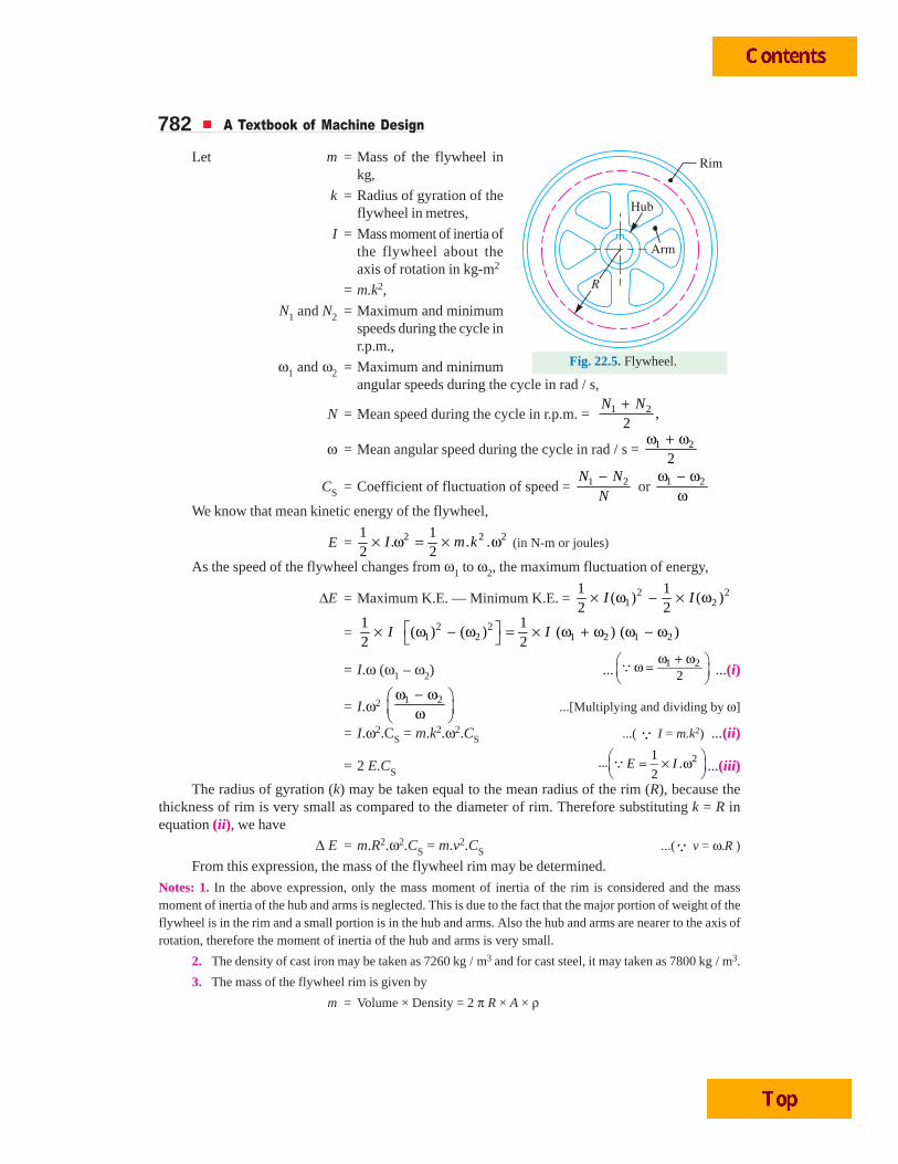
Let m = Mass of the flywheel inkg,
k = Radius of gyration of theflywheel in metres,
I = Mass moment of inertia ofthe flywheel about theaxis of rotation in kg-m2
= m.k2,
N1 and N2 = Maximum and minimumspeeds during the cycle inr.p.m.,
ω1 and ω2 = Maximum and minimumangular speeds during the cycle in rad / s,
N = Mean speed during the cycle in r.p.m. = 1 2 ,2
N N+
ω = Mean angular speed during the cycle in rad / s = 1 2
2ω + ω
CS = Coefficient of fluctuation of speed = 1 2−N NN
or 1 2ω − ωω
We know that mean kinetic energy of the flywheel,
E = 2 2 21 1. . .
2 2I m k× ω = × ω (in N-m or joules)
As the speed of the flywheel changes from ω1 to ω2, the maximum fluctuation of energy,
ΔE = Maximum K.E. — Minimum K.E. = 2 21 2
1 1( ) ( )
2 2× ω − × ωI I
=12
× I 2 21 2 1 2 1 2
1( ) ( ) ( ) ( )
2I⎡ ⎤ω − ω = × ω + ω ω − ω⎣ ⎦
= I.ω (ω1 – ω2) ... 1 22
ω + ω⎛ ⎞ω =⎜ ⎟⎝ ⎠Q ...(i)
= I.ω2 1 2ω − ω⎛ ⎞
⎜ ⎟ω⎝ ⎠...[Multiplying and dividing by ω]
= I.ω2.CS = m.k2.ω2.CS ...( Q I = m.k2) ...(ii)
= 2 E.CS21
... .2
⎛ ⎞= × ω⎜ ⎟⎝ ⎠QE I ...(iii)
The radius of gyration (k) may be taken equal to the mean radius of the rim (R), because thethickness of rim is very small as compared to the diameter of rim. Therefore substituting k = R inequation (ii), we have
Δ E = m.R2.ω2.CS = m.v2.CS ...(Q v = ω.R )
From this expression, the mass of the flywheel rim may be determined.
Notes: 1. In the above expression, only the mass moment of inertia of the rim is considered and the massmoment of inertia of the hub and arms is neglected. This is due to the fact that the major portion of weight of theflywheel is in the rim and a small portion is in the hub and arms. Also the hub and arms are nearer to the axis ofrotation, therefore the moment of inertia of the hub and arms is very small.
2. The density of cast iron may be taken as 7260 kg / m3 and for cast steel, it may taken as 7800 kg / m3.
3. The mass of the flywheel rim is given by
m = Volume × Density = 2 π R × A × ρ
Flywheel 783
From this expression, we may find the value of the cross-sectional area of the rim. Assuming thecross-section of the rim to be rectangular, then
A = b × t
where b = Width of the rim, and
t = Thickness of the rim.
Knowing the ratio of b / t which is usually taken as 2, we may find the width and thickness of rim.
4. When the flywheel is to be used as a pulley, then the width of rim should be taken 20 to 40 mm greaterthan the width of belt.
Example 22.1. The turning moment diagram for a petrol engine is drawn to the followingscales:
Turning moment, 1 mm = 5 N-m;Crank angle, 1 mm = 1º.
The turning moment diagram repeatsitself at every half revolution of the engineand the areas above and below the meanturning moment line, taken in order are295, 685, 40, 340, 960, 270 mm2.
Determine the mass of 300 mmdiameter flywheel rim when the coefficientof fluctuation of speed is 0.3% and theengine runs at 1800 r.p.m. Also determinethe cross-section of the rim when the widthof the rim is twice of thickness. Assumedensity of rim material as 7250 kg / m3.
Solution. Given : D = 300 mm orR = 150 mm = 0.15 m ; CS = 0.3% = 0.003 ; N = 1800 r.p.m. or ω = 2 π × 1800 / 60 = 188.5 rad/s ;ρ = 7250 kg / m3
Mass of the flywheelLet m = Mass of the flywheel in kg.
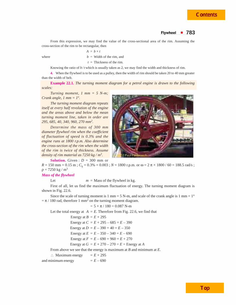
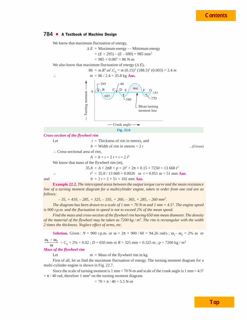
First of all, let us find the maximum fluctuation of energy. The turning moment diagram isshown in Fig. 22.6.
Since the scale of turning moment is 1 mm = 5 N-m, and scale of the crank angle is 1 mm = 1°= π / 180 rad, therefore 1 mm2 on the turning moment diagram.
= 5 × π / 180 = 0.087 N-m
Let the total energy at A = E. Therefore from Fig. 22.6, we find that
Energy at B = E + 295
Energy at C = E + 295 – 685 = E – 390
Energy at D = E – 390 + 40 = E – 350
Energy at E = E – 350 – 340 = E – 690
Energy at F = E – 690 + 960 = E + 270
Energy at G = E + 270 – 270 = E = Energy at A
From above we see that the energy is maximum at B and minimum at E.
∴ Maximum energy = E + 295
and minimum energy = E – 690
784 A Textbook of Machine Design
We know that maximum fluctuation of energy,Δ E = Maximum energy — Minimum energy
= (E + 295) – (E – 690) = 985 mm2
= 985 × 0.087 = 86 N-mWe also know that maximum fluctuation of energy (Δ E),
86 = m.R2.ω2.CS = m (0.15)2 (188.5)2 (0.003) = 2.4 m∴ m = 86 / 2.4 = 35.8 kg Ans.
Fig. 22.6
Cross-section of the flywheel rimLet t = Thickness of rim in metres, and
b = Width of rim in metres = 2 t ...(Given)
∴ Cross-sectional area of rim,A = b × t = 2 t × t = 2 t2
We know that mass of the flywheel rim (m),35.8 = A × 2πR × ρ = 2t2 × 2π × 0.15 × 7250 = 13 668 t2
∴ t2 = 35.8 / 13 668 = 0.0026 or t = 0.051 m = 51 mm Ans.and b = 2 t = 2 × 51 = 102 mm Ans.
Example 22.2. The intercepted areas between the output torque curve and the mean resistanceline of a turning moment diagram for a multicylinder engine, taken in order from one end are asfollows:
– 35, + 410, – 285, + 325, – 335, + 260, – 365, + 285, – 260 mm2.The diagram has been drawn to a scale of 1 mm = 70 N-m and 1 mm = 4.5°. The engine speed
is 900 r.p.m. and the fluctuation in speed is not to exceed 2% of the mean speed.Find the mass and cross-section of the flywheel rim having 650 mm mean diameter. The density
of the material of the flywheel may be taken as 7200 kg / m3. The rim is rectangular with the width2 times the thickness. Neglect effect of arms, etc.
Solution. Given : N = 900 r.p.m. or ω = 2π × 900 / 60 = 94.26 rad/s ; ω1– ω2 = 2% ω or
1 2ω − ωω = CS = 2% = 0.02 ; D = 650 mm or R = 325 mm = 0.325 m ; ρ = 7200 kg / m3
Mass of the flywheel rimLet m = Mass of the flywheel rim in kg.First of all, let us find the maximum fluctuation of energy. The turning moment diagram for a
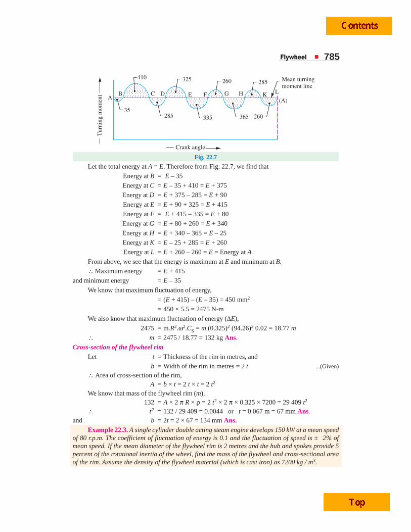
multi-cylinder engine is shown in Fig. 22.7.
Since the scale of turning moment is 1 mm = 70 N-m and scale of the crank angle is 1 mm = 4.5º= π / 40 rad, therefore 1 mm2 on the turning moment diagram.
= 70 × π / 40 = 5.5 N-m
Flywheel 785
Fig. 22.7
Let the total energy at A = E. Therefore from Fig. 22.7, we find that
Energy at B = E – 35
Energy at C = E – 35 + 410 = E + 375
Energy at D = E + 375 – 285 = E + 90
Energy at E = E + 90 + 325 = E + 415
Energy at F = E + 415 – 335 = E + 80
Energy at G = E + 80 + 260 = E + 340
Energy at H = E + 340 – 365 = E – 25
Energy at K = E – 25 + 285 = E + 260
Energy at L = E + 260 – 260 = E = Energy at A
From above, we see that the energy is maximum at E and minimum at B.
∴ Maximum energy = E + 415
and minimum energy = E – 35
We know that maximum fluctuation of energy,
= (E + 415) – (E – 35) = 450 mm2
= 450 × 5.5 = 2475 N-m
We also know that maximum fluctuation of energy (ΔE),
2475 = m.R2.ω2.CS = m (0.325)2 (94.26)2 0.02 = 18.77 m
∴ m = 2475 / 18.77 = 132 kg Ans.
Cross-section of the flywheel rimLet t = Thickness of the rim in metres, and
b = Width of the rim in metres = 2 t ...(Given)
∴ Area of cross-section of the rim,A = b × t = 2 t × t = 2 t2
We know that mass of the flywheel rim (m),132 = A × 2 π R × ρ = 2 t2 × 2 π × 0.325 × 7200 = 29 409 t2
∴ t2 = 132 / 29 409 = 0.0044 or t = 0.067 m = 67 mm Ans.and b = 2t = 2 × 67 = 134 mm Ans.
Example 22.3. A single cylinder double acting steam engine develops 150 kW at a mean speedof 80 r.p.m. The coefficient of fluctuation of energy is 0.1 and the fluctuation of speed is ± 2% ofmean speed. If the mean diameter of the flywheel rim is 2 metres and the hub and spokes provide 5percent of the rotational inertia of the wheel, find the mass of the flywheel and cross-sectional areaof the rim. Assume the density of the flywheel material (which is cast iron) as 7200 kg / m3.

786 A Textbook of Machine Design
Solution. Given : P = 150 kW = 150 × 103 W ; N = 80 r.p.m. ; CE = 0.1; ω1 – ω2= ± 2% ω ; D = 2 m or R = 1 m ; ρ = 7200 kg/m3
Mass of the flywheel rimLet m = Mass of the flywheel rim in kg.
We know that the mean angular speed,
ω = 2 2 80
60 60π π ×=N
= 8.4 rad / s
Since the fluctuation of speed is ± 2% of mean speed (ω), therefore total fluctuation of speed,
ω1 – ω2 = 4 % ω = 0.04 ωand coefficient of fluctuation of speed,
CS = 1 2ω − ωω = 0.04
We know that the work done by the flywheel per cycle
= 360 150 10 60
80P
N× × ×= = 112 500 N-m
We also know that coefficient of fluctuation of energy,
CE = Maximum fluctuation of energy
Workdone / cycle∴ Maximum fluctuation of energy,
ΔE = CE × Workdone / cycle
= 0.1 × 112 500 = 11 250 N-m
Since 5% of the rotational inertia is provided by hub and spokes, therefore the maximumfluctuation of energy of the flywheel rim will be 95% of the flywheel.
∴ Maximum fluctuation of energy of the rim,
(Δ E)rim = 0.95 × 11 250 = 10 687.5 N-m
We know that maximum fluctuation of energy of the rim (Δ E)rim,
10 687.5 = m.R2.ω2.CS = m × 12 (8.4)2 0.04 = 2.82 m
∴ m = 10 687.5 / 2.82 = 3790 kg Ans.
Cross-sectional area of the rim
Let A = Cross-sectional area of the rim.
We know that the mass of the flywheel rim (m),
3790 = A × 2πR × ρ = A × 2π × 1 × 7200 = 45 245 A
∴ A = 3790 / 45 245 = 0.084 m2 Ans.Example 22.4. A single cylinder, single acting, four stroke oil engine develops 20 kW at
300 r.p.m. The workdone by the gases during the expansion stroke is 2.3 times the workdone on thegases during the compression and the workdone during the suction and exhaust strokes is negligible.The speed is to be maintained within ± 1%. Determine the mass moment of inertia of the flywheel.
Solution. Given : P = 20 kW = 20 × 103 W ; N = 300 r.p.m. or ω = 2π × 300 / 60= 31.42 rad / s ; ω1 – ω2 = ± 1% ω
First of all, let us find the maximum fluctuation of energy (ΔE). The turning moment diagramfor a four stroke engine is shown in Fig. 22.8. It is assumed to be triangular during compression andexpansion strokes, neglecting the suction and exhaust strokes.
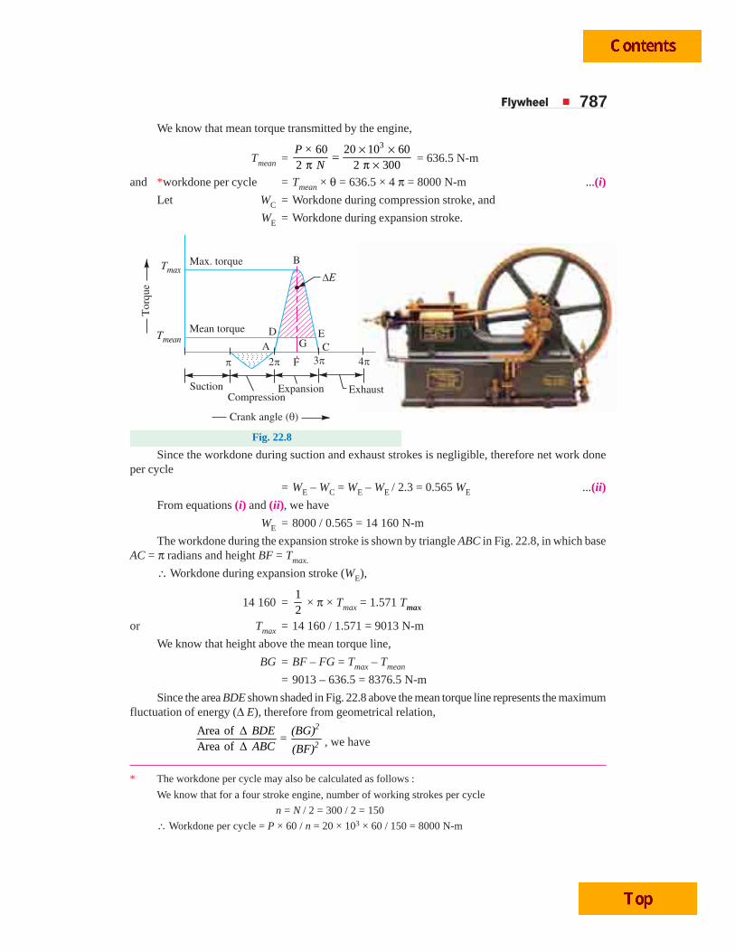
Flywheel 787We know that mean torque transmitted by the engine,
Tmean = 360 20 10 60
2 2 300× ×=
π π ×P ×
N = 636.5 N-m
and *workdone per cycle = Tmean × θ = 636.5 × 4 π = 8000 N-m ...(i)
Let WC = Workdone during compression stroke, and
WE = Workdone during expansion stroke.
Fig. 22.8
Since the workdone during suction and exhaust strokes is negligible, therefore net work doneper cycle
= WE – WC = WE – WE / 2.3 = 0.565 WE ...(ii)
From equations (i) and (ii), we have
WE = 8000 / 0.565 = 14 160 N-m
The workdone during the expansion stroke is shown by triangle ABC in Fig. 22.8, in which baseAC = π radians and height BF = Tmax.
∴ Workdone during expansion stroke (WE),
14 160 =12
× π × Tmax = 1.571 Tmax
or Tmax = 14 160 / 1.571 = 9013 N-m
We know that height above the mean torque line,
BG = BF – FG = Tmax – Tmean
= 9013 – 636.5 = 8376.5 N-m
Since the area BDE shown shaded in Fig. 22.8 above the mean torque line represents the maximumfluctuation of energy (Δ E), therefore from geometrical relation,
Area of ΔArea of Δ
2
2
BDE (BG)=
ABC (BF), we have
* The workdone per cycle may also be calculated as follows :
We know that for a four stroke engine, number of working strokes per cycle
n = N / 2 = 300 / 2 = 150
∴ Workdone per cycle = P × 60 / n = 20 × 103 × 60 / 150 = 8000 N-m
788 A Textbook of Machine Design
* The maximum fluctuation of energy (ΔE) may also be obtained as discussed below :From similar triangles BDE and BAC,
DE BGAC BF
= or DE = 8376.5
2.92 rad9013
πBG× AC = × =
BF∴ Maximum fluctuation of energy (i.e. area of Δ BDE),
ΔE = 1 1
2.92 8376.5 12 230 N-m2 2
× × = × × =DE BG
Maximum fluctuation of energy (i.e. area of Δ BDE),
*ΔE = Area of Δ ABC 2
BGBF
⎛ ⎞⎜ ⎟⎝ ⎠
= WE 2
BGBF
⎛ ⎞⎜ ⎟⎝ ⎠
= 14 160 2
8376.59013
⎛ ⎞⎜ ⎟⎝ ⎠
= 12 230 N-m
Since the speed is to be maintained within ± 1% of the mean speed, therefore total fluctuation ofspeed
ω1 – ω2 = 2 % ω = 0.02 ωand coefficient of fluctuation of speed,
CS = 1 2ω − ωω = 0.02
Let I = Mass moment of inertia of the flywheel in kg-m2.
We know that maximum fluctuation of energy (ΔE),
12 230 = I.ω2.CS
= I (31.42)2 0.02 = 19.74 I
∴ I = 12 230 / 19.74 = 619.5 kg-m2 Ans.
22.7 Stresses in a Flywheel RimA flywheel, as shown in Fig. 22.9, consists of a
rim at which the major portion of the mass or weightof flywheel is concentrated, a boss or hub for fixingthe flywheel on to the shaft and a number of arms forsupporting the rim on the hub.
The following types of stresses are induced inthe rim of a flywheel:
1. Tensile stress due to centrifugal force,2. Tensile bending stress caused by the restraint
of the arms, and3. The shrinkage stresses due to unequal rate
of cooling of casting. These stresses may bevery high but there is no easy method of de-termining. This stress is taken care of by afactor of safety.
We shall now discuss the first two types ofstresses as follows:
1. Tensile stress due to the centrifugal forceThe tensile stress in the rim due to the centrifugal force, assuming that the rim is unstrained by
the arms, is determined in a similar way as a thin cylinder subjected to internal pressure.
Let b = Width of rim,
t = Thickness of rim,
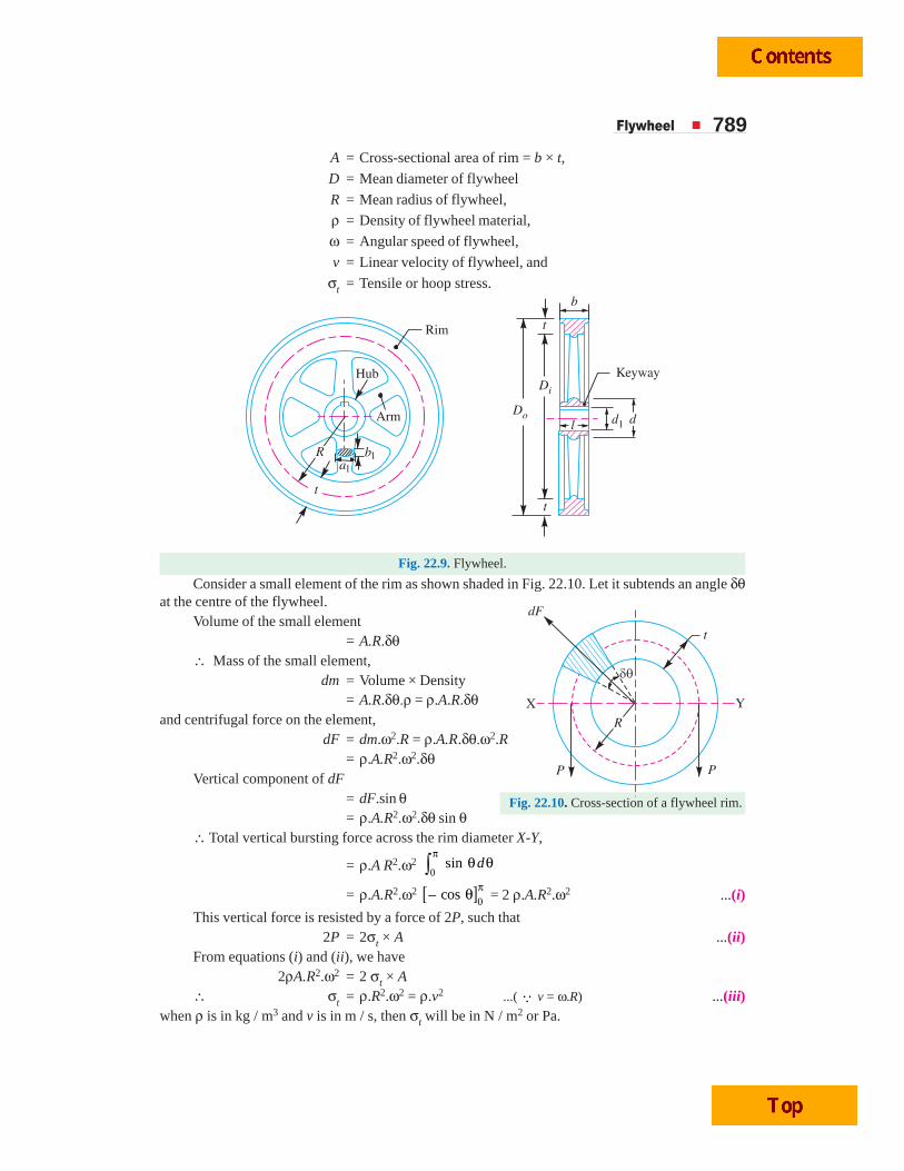
Flywheel 789A = Cross-sectional area of rim = b × t,
D = Mean diameter of flywheel
R = Mean radius of flywheel,
ρ = Density of flywheel material,
ω = Angular speed of flywheel,
v = Linear velocity of flywheel, and
σt = Tensile or hoop stress.
Fig. 22.9. Flywheel.
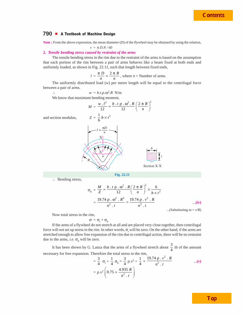
Consider a small element of the rim as shown shaded in Fig. 22.10. Let it subtends an angle δθat the centre of the flywheel.
Volume of the small element= A.R.δθ
∴ Mass of the small element,dm = Volume × Density
= A.R.δθ.ρ = ρ.A.R.δθand centrifugal force on the element,
dF = dm.ω2.R = ρ.A.R.δθ.ω2.R= ρ.A.R2.ω2.δθ
Vertical component of dF= dF.sin θ= ρ.A.R2.ω2.δθ sin θ
∴ Total vertical bursting force across the rim diameter X-Y,
= ρ.A R2.ω2 0
sin dπ
θ θ∫= ρ.A.R2.ω2 [ ]0
– cosπθ = 2 ρ.A.R2.ω2 ...(i)
This vertical force is resisted by a force of 2P, such that2P = 2σt × A ...(ii)
From equations (i) and (ii), we have2ρA.R2.ω2 = 2 σt × A
∴ σt = ρ.R2.ω2 = ρ.v2 ...( Q v = ω.R) ...(iii)when ρ is in kg / m3 and v is in m / s, then σt will be in N / m2 or Pa.
Fig. 22.10. Cross-section of a flywheel rim.
790 A Textbook of Machine Design
Note : From the above expression, the mean diameter (D) of the flywheel may be obtained by using the relation,
v = π D.N / 60
2. Tensile bending stress caused by restraint of the armsThe tensile bending stress in the rim due to the restraint of the arms is based on the assumption
that each portion of the rim between a pair of arms behaves like a beam fixed at both ends anduniformly loaded, as shown in Fig. 22.11, such that length between fixed ends,
l = 2D R
n nπ π= , where n = Number of arms.
The uniformly distributed load (w) per metre length will be equal to the centrifugal forcebetween a pair of arms.
∴ w = b.t.ρ.ω2.R N/mWe know that maximum bending moment,
M =22 2. . . . 2
12 12ρ ω π⎛ ⎞= ⎜ ⎟
⎝ ⎠
w l b t R Rn
and section modulus, Z = 216
b t×
Fig. 22.11∴ Bending stress,
σb = 22
2
. . . 2 612
M b t R RZ n b t
ρ ω π⎛ ⎞= ×⎜ ⎟ ×⎝ ⎠
= 2 3 2
2 2
19.74 . . 19.74 . .
. .
R v R
n t n t
ρ ω ρ= ...(iv)
...(Substituting ω = v/R)
Now total stress in the rim,σ = σt + σb
If the arms of a flywheel do not stretch at all and are placed very close together, then centrifugalforce will not set up stress in the rim. In other words, σt will be zero. On the other hand, if the arms arestretched enough to allow free expansion of the rim due to centrifugal action, there will be no restraintdue to the arms, i.e. σb will be zero.
It has been shown by G. Lanza that the arms of a flywheel stretch about 34
th of the amount
necessary for free expansion. Therefore the total stress in the rim,
= 34
σt + 14
σb = 34
ρ.v2 + 14
× 2
2
19.74 . .
.
v R
n t
ρ...(v)
= ρ.v2 2
4.9350.75
.
R
n t
⎛ ⎞+⎜ ⎟⎜ ⎟
⎝ ⎠
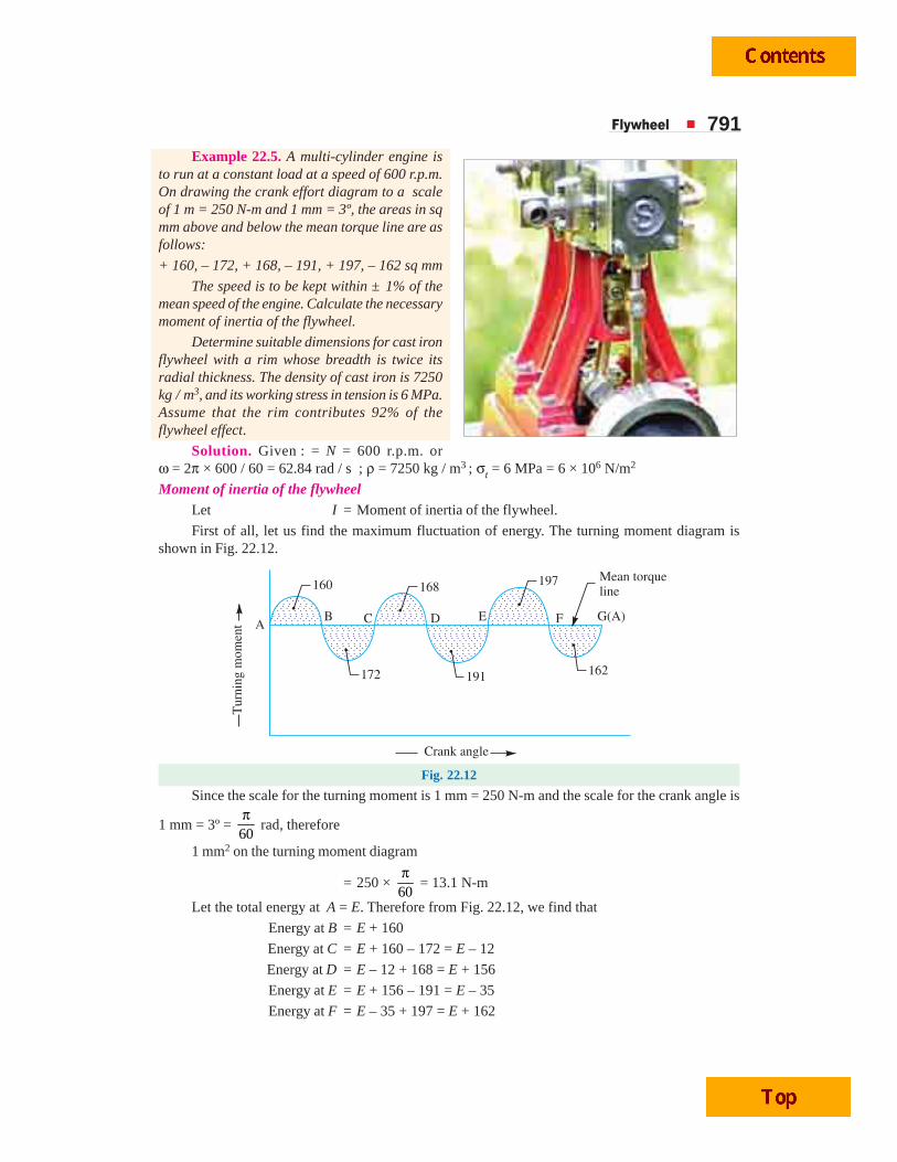
Flywheel 791Example 22.5. A multi-cylinder engine is
to run at a constant load at a speed of 600 r.p.m.On drawing the crank effort diagram to a scaleof 1 m = 250 N-m and 1 mm = 3º, the areas in sqmm above and below the mean torque line are asfollows:
+ 160, – 172, + 168, – 191, + 197, – 162 sq mm
The speed is to be kept within ± 1% of themean speed of the engine. Calculate the necessarymoment of inertia of the flywheel.
Determine suitable dimensions for cast ironflywheel with a rim whose breadth is twice itsradial thickness. The density of cast iron is 7250kg / m3, and its working stress in tension is 6 MPa.Assume that the rim contributes 92% of theflywheel effect.
Solution. Given : = N = 600 r.p.m. orω = 2π × 600 / 60 = 62.84 rad / s ; ρ = 7250 kg / m3 ; σt = 6 MPa = 6 × 10⁶ N/m2
Moment of inertia of the flywheelLet I = Moment of inertia of the flywheel.
First of all, let us find the maximum fluctuation of energy. The turning moment diagram isshown in Fig. 22.12.
Fig. 22.12
Since the scale for the turning moment is 1 mm = 250 N-m and the scale for the crank angle is
1 mm = 3º = 60π
rad, therefore
1 mm2 on the turning moment diagram
= 250 × 60π
= 13.1 N-m
Let the total energy at A = E. Therefore from Fig. 22.12, we find that
Energy at B = E + 160
Energy at C = E + 160 – 172 = E – 12
Energy at D = E – 12 + 168 = E + 156
Energy at E = E + 156 – 191 = E – 35
Energy at F = E – 35 + 197 = E + 162
792 A Textbook of Machine Design
Energy at G = E + 162 – 162 = E = Energy at A
From above, we find that the energy is maximum at F and minimum at E.
∴ Maximum energy = E + 162
and minimum energy = E – 35
We know that the maximum fluctuation of energy,
Δ E = Maximum energy – Minimum energy
= (E + 162) – (E – 35) = 197 mm2 = 197 × 13.1 = 2581 N-m
Since the fluctuation of speed is ± 1% of the mean speed (ω), therefore total fluctuation ofspeed,
ω1 – ω2 = 2% ω = 0.02 ωand coefficient of fluctuation of speed,
CS = 1 2ω − ωω = 0.02
We know that the maximum fluctuation of energy (ΔE),
2581 = I.ω2.CS = I (62.84)2 0.02 = 79 I
∴ I = 2581 / 79 = 32.7 kg-m2 Ans.
Dimensions of a flywheel rim
Let t = Thickness of the flywheel rim in metres, and
b = Breadth of the flywheel rim in metres = 2 t ...(Given)
First of all let us find the peripheral velocity (v) and mean diameter (D) of the flywheel.
We know that tensile stress (σt ),
6 × 106 = ρ.v2 = 7250 × v2
∴ v2 = 6 × 10⁶ / 7250 = 827.6 or v = 28.76 m/s
We also know that peripheral velocity (v),
28.76 = . 600
60 60D N Dπ π ×= = 31.42 D
∴ D = 28.76 / 31.42 = 0.915 m = 915 mm Ans.
Now let us find the mass of the flywheel rim. Since the rim contributes 92% of the flywheeleffect, therefore the energy of the flywheel rim (Erim) will be 0.92 times the total energy of the flywheel(E). We know that maximum fluctuation of energy (ΔE),
2581 = E × 2 CS = E × 2 × 0.02 = 0.04 E
∴ E = 2581 / 0.04 = 64 525 N-m
and energy of the flywheel rim,
Erim = 0.92 E = 0.92 × 64 525 = 59 363 N-m
Let m = Mass of the flywheel rim.
We know that energy of the flywheel rim (Erim),
59 363 = 12
× m × v2 = 12
× m (28.76)2 = 413.6 m
∴ m = 59 363 / 413.6 = 143.5 kg
We also know that mass of the flywheel rim (m),
143.5 = b × t × π D × ρ = 2 t × t × π × 0.915 × 7250 = 41 686 t2
Flywheel 793∴ t2 = 143.5 / 41 686 = 0.003 44
or t = 0.0587 say 0.06 m = 60 mm Ans.
and b = 2 t = 2 × 60 = 120 mm Ans.Notes: The mass of the flywheel rim may also be obtained by using the following relations. Since the rimcontributes 92% of the flywheel effect, therefore using
1. Irim = 0.92 Iflywheel or m.k2 = 0.92 × 32.7 = 30 kg–m2
Since radius of gyration, k = R = D / 2 = 0.915 / 2 = 0.4575 m, therefore
m = 2
30
k = 2
30
(0.4575) = 30
0.209 = 143.5 kg
2. (Δ E)rim = 0.92 (Δ E)flywheel
m.v2.CS = 0.92 (Δ E)flywheel
m (28.76)2 0.02 = 0.92 × 2581
16.55 m = 2374.5 or m = 2374.5 / 16.55 = 143.5 kg
Example 22.6. The areas of the turning moment diagram for one revolution of a multi-cylinderengine with reference to the mean turning moment, below and above the line, are
– 32, + 408, – 267, + 333, – 310, + 226, – 374, + 260 and – 244 mm2.
The scale for abscissa and ordinate are: 1 mm = 2.4° and 1 mm = 650 N-m respectively. Themean speed is 300 r.p.m. with a percentage speed fluctuation of ± 1.5%. If the hoop stress in thematerial of the rim is not to exceed 5.6 MPa, determine the suitable diameter and cross-section forthe flywheel, assuming that the width is equal to 4 times the thickness. The density of the materialmay be taken as 7200 kg / m3. Neglect the effect of the boss and arms.
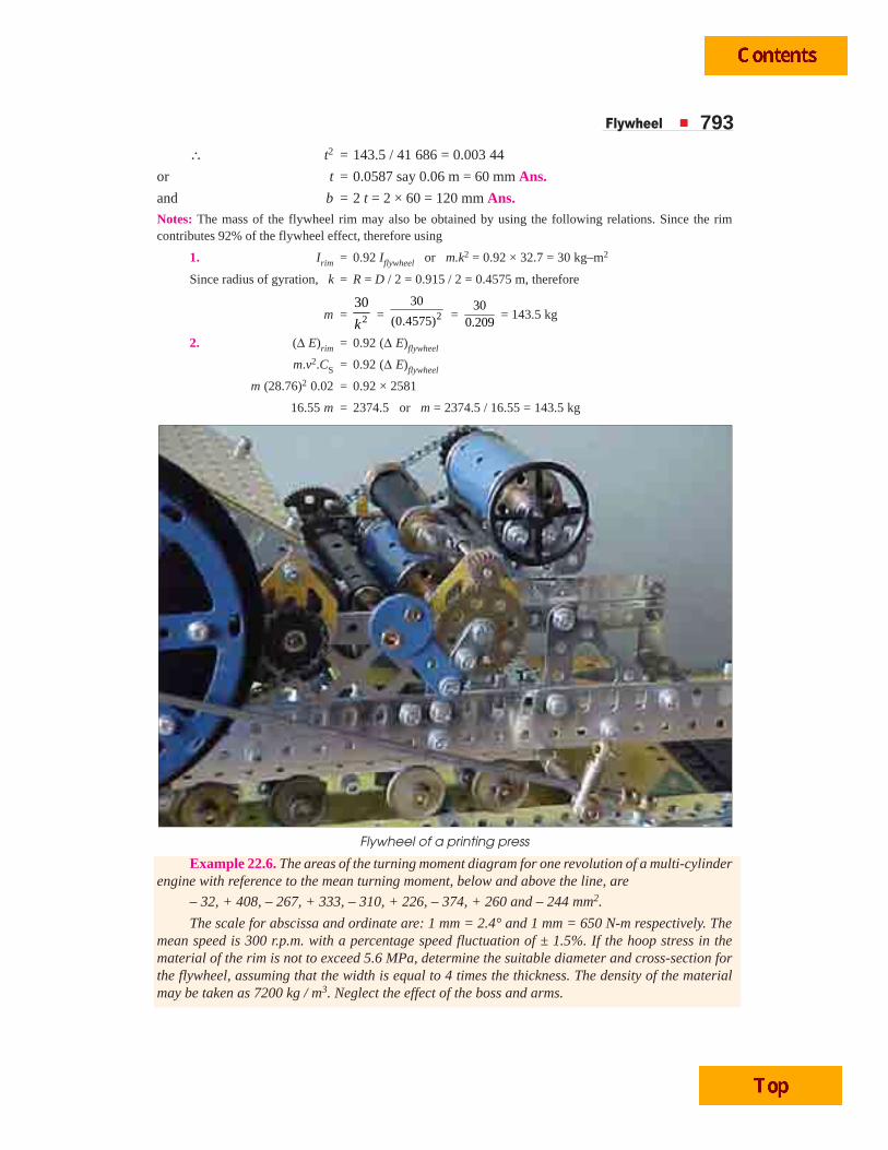
Flywheel of a printing press
794 A Textbook of Machine Design
Solution. Given : N = 300 r.p.m. or ω = 2 π × 300/60 = 31.42 rad/s ; σt = 5.6 MPa= 5.6 × 10⁶ N/m2 ; ρ = 7200 kg/m3
Diameter of the flywheel
Let D = Diameter of the flywheel in metres.
We know that peripheral velocity of the flywheel,
v = . 300
60 60D N Dπ π ×= = 15.71 D m/s
We also know that hoop stress (σt ),
5.6 × 106 = ρ × v2 = 7200 (15.71 D)2 = 1.8 × 10⁶ D2
∴ D 2 = 5.6 × 10⁶ / 1.8 × 106 = 3.11 or D = 1.764 m Ans.
Cross-section of the flywheel
Let t = Thickness of the flywheel rim in metres, and
b = Width of the flywheel rim in metres = 4 t ...(Given)
∴ Cross-sectional area of the rim,
A = b × t = 4 t × t = 4 t2 m2
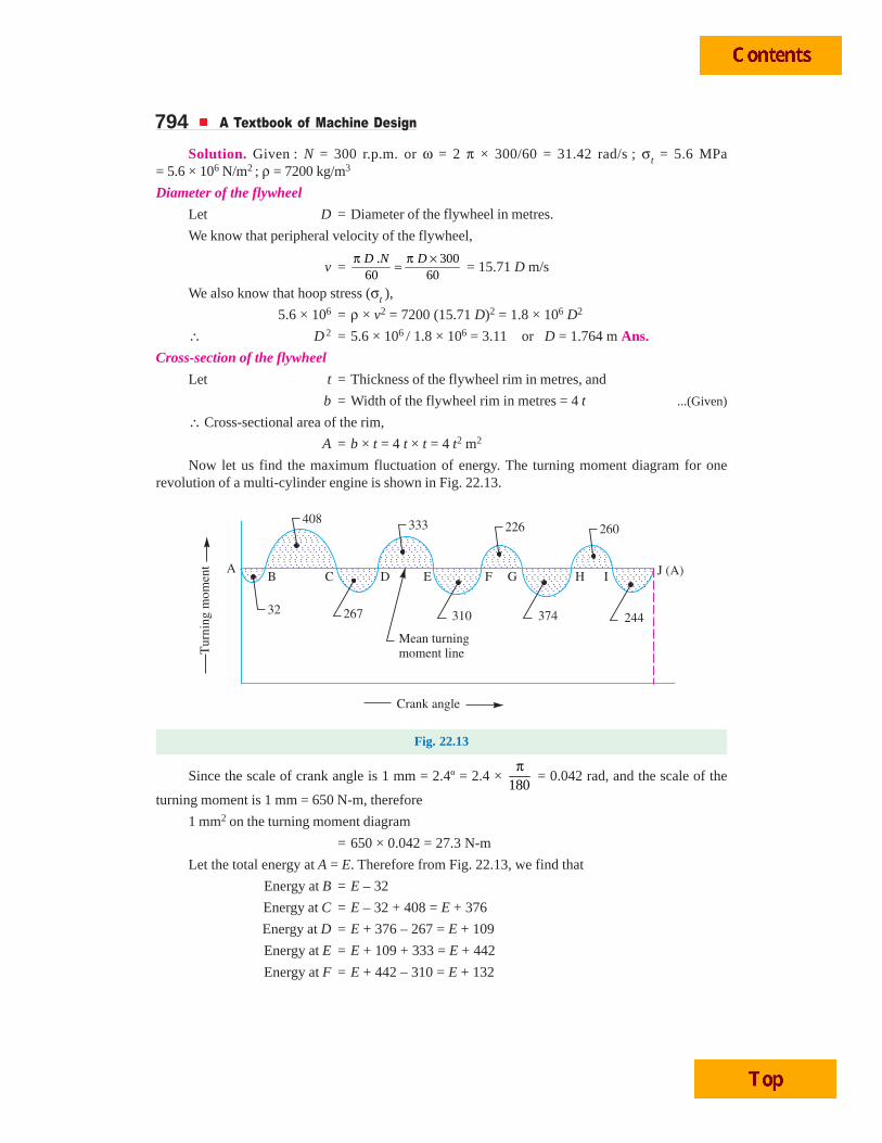
Now let us find the maximum fluctuation of energy. The turning moment diagram for onerevolution of a multi-cylinder engine is shown in Fig. 22.13.
Fig. 22.13
Since the scale of crank angle is 1 mm = 2.4º = 2.4 × 180
π = 0.042 rad, and the scale of the
turning moment is 1 mm = 650 N-m, therefore
1 mm2 on the turning moment diagram
= 650 × 0.042 = 27.3 N-m
Let the total energy at A = E. Therefore from Fig. 22.13, we find that
Energy at B = E – 32
Energy at C = E – 32 + 408 = E + 376
Energy at D = E + 376 – 267 = E + 109
Energy at E = E + 109 + 333 = E + 442
Energy at F = E + 442 – 310 = E + 132
Flywheel 795Energy at G = E + 132 + 226 = E + 358
Energy at H = E + 358 – 374 = E – 16
Energy at I = E – 16 + 260 = E + 244
Energy at J = E + 244 – 244 = E = Energy at A
From above, we see that the energy is maximum at E and minimum at B.
∴ Maximum energy = E + 442
and minimum energy = E – 32
We know that maximum fluctuation of energy,
Δ E = Maximum energy – Minimum energy
= (E + 442) – (E – 32) = 474 mm2
= 474 × 27.3 = 12 940 N-m
Since the fluctuation of speed is ± 1.5% of the mean speed, therefore total fluctuation of speed,
ω1 – ω2 = 3% of mean speed = 0.03 ωand coefficient of fluctuation of speed,
CS = 1 2ω − ωω = 0.03
Let m = Mass of the flywheel rim.
We know that maximum fluctuation of energy (ΔE),
12 940 = m.R2.ω2.CS = m 2
1.7642
⎛ ⎞⎜ ⎟⎝ ⎠
(31.42)2 0.03 = 23 m
∴ m = 12 940 / 23 = 563 kg Ans.
We also know that mass of the flywheel rim (m),
563 = A × π D × ρ = 4 t2 × π × 1.764 × 7200 = 159 624 t2
∴ t2 = 563 / 159 624 = 0.00353
or t = 0.0594 m = 59.4 say 60 mm Ans.
and b = 4 t = 4 × 60 = 240 mm Ans.
Example 22.7. An otto cycle engine develops 50 kW at 150 r.p.m. with 75 explosions perminute. The change of speed from the commencement to the end of power stroke must not exceed0.5% of mean on either side. Design a suitable rim section having width four times the depth so thatthe hoop stress does not exceed 4 MPa. Assume that the flywheel stores 16/15 times the energy storedby the rim and that the workdone during power stroke is 1.40 times the workdone during the cycle.Density of rim material is 7200 kg / m3.
Solution. Given : P = 50 kW = 50 × 103 W ; N = 150 r.p.m. ; n = 75 ; σt = 4 MPa = 4 × 10⁶ N/m2 ;ρ = 7200 kg/m3
First of all, let us find the mean torque (Tmean) transmitted by the engine or flywheel. We knowthat the power transmitted (P),
50 × 103 = 2
60meanN Tπ ×
= 15.71 Tmean
∴ Tmean = 50 × 103 / 15.71 = 3182.7 N-m
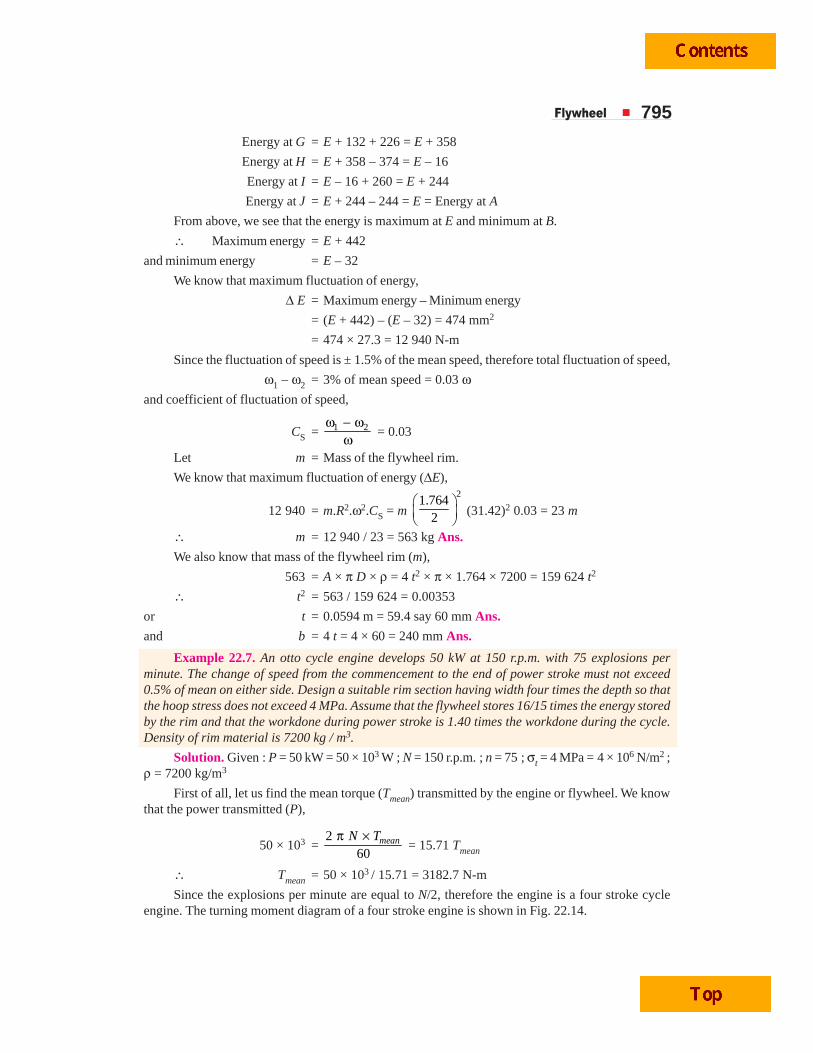
Since the explosions per minute are equal to N/2, therefore the engine is a four stroke cycleengine. The turning moment diagram of a four stroke engine is shown in Fig. 22.14.
796 A Textbook of Machine Design
We know that *workdone per cycle
= Tmean × θ = 3182.7 × 4 π = 40 000 N-m
∴ Workdone during power or working stroke
= 1.4 × 40 000 = 56 000 N-m ...(i)
Fig. 22.14
The workdone during power or working stroke is shown by a triangle ABC in Fig. 22.14 inwhich base AC = π radians and height BF = Tmax.
∴ Workdone during working stroke
= 12
× π × Tmax = 1.571 Tmax ...(ii)
From equations (i) and (ii), we have
Tmax = 56 000 / 1.571 = 35 646 N-m
Height above the mean torque line,
BG = BF – FG = Tmax – Tmean = 35 646 – 3182.7 = 32 463.3 N-m
Since the area BDE (shown shaded in Fig. 22.14) above the mean torque line represents themaximum fluctuation of energy (ΔE), therefore from geometrical relation
Area ofArea of
BDEABC
ΔΔ =
2
2
( )
( )
BG
BF , we have
Maximum fluctuation of energy (i.e. area of triangle BDE),
Δ E = Area of triangle ABC × 2
BGBF
⎛ ⎞⎜ ⎟⎝ ⎠
= 56 000 × 2
32 463.335 646
⎛ ⎞⎜ ⎟⎝ ⎠
= 56 000 × 0.83 = 46 480 N-m
Mean diameter of the flywheelLet D = Mean diameter of the flywheel in metres, and
v = Peripheral velocity of the flywheel in m/s.
* The workdone per cycle for a four stroke engine is also given by
Workdone / cycle =60
Number of explosion / min×P
= 60×P
n =
50 000 6075
× = 40 000 N-m
Flywheel 797We know that hoop stress (σt),
4 × 106 = ρ.v2 = 7200 × v2
∴ v2 = 4 × 10⁶ / 7200 = 556
or v = 23.58 m/s
We also know that peripheral velocity (v),
23.58 = 150
60 60D N Dπ π ×= = 7.855 D
∴ D = 23.58 / 7.855 = 3 m Ans.Cross-sectional dimensions of the rim
Let t =Thickness of the rim in metres, and
b = Width of the rim in metres = 4 t
...(Given)∴ Cross-sectional area of the rim,
A = b × t = 4 t × t = 4 t2
First of all, let us find the mass of the flywheel rim.Let m = Mass of the flywheel rim, and
E = Total energy of the flywheel.Since the fluctuation of speed is 0.5% of the mean speed on either side, therefore total fluctuation
of speed,N1 – N2 = 1% of mean speed = 0.01 N
and coefficient of fluctuation of speed,
CS = 1 2N NN−
= 0.01
We know that the maximum fluctuation of energy (Δ E),
46 480 = E × 2 CS = E × 2 × 0.01 = 0.02 E
∴ E = 46 480 / 0.02 = 2324 × 103 N-m
Since the energy stored by the flywheel is 16
15 times the energy stored by the rim, therefore the
energy of the rim,
Erim = 1516
E = 1516
× 2324 × 103 = 2178.8 × 103 N-m
We know that energy of the rim (Erim),
2178.8 × 103 = 12
× m × v2 = 12
× m (23.58)2 = 278 m
∴ m = 2178.8 × 103 / 278 = 7837 kg
We also know that mass of the flywheel rim (m),
7837 = A × π D × ρ = 4 t2 × π × 3 × 7200 = 271 469 t2
∴ t 2 = 7837 / 271 469 = 0.0288 or t = 0.17 m = 170 mm Ans.
and b = 4 t = 4 × 170 = 680 mm Ans.
Example 22.8. A shaft fitted with a flywheel rotates at 250 r.p.m. and drives a machine. Thetorque of machine varies in a cyclic manner over a period of 3 revolutions. The torque rises from750 N-m to 3000 N-m uniformly during 1 / 2 revolution and remains constant for the following revolution.It then falls uniformly to 750 N-m during the next 1 / 2 revolution and remains constant for one revolution,the cycle being repeated thereafter. Determine the power required to drive the machine.
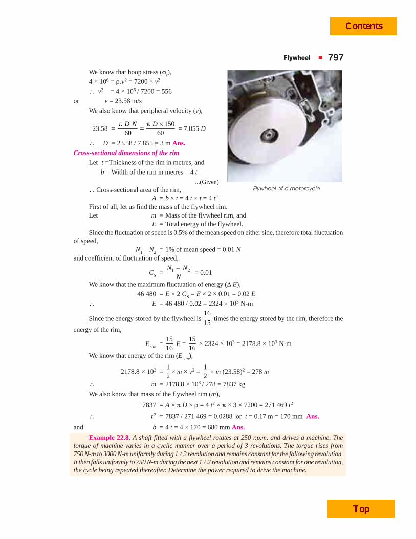
Flywheel of a motorcycle
798 A Textbook of Machine Design
If the total fluctuation of speed is not to exceed 3% of the mean speed, determine a suitablediameter and cross-section of the flywheel rim. The width of the rim is to be 4 times the thickness andthe safe centrifugal stress is 6 MPa. The material density may be assumed as 7200 kg / m3.
Solution. Given : N = 250 r.p.m. or ω = 2 π × 250 / 60 = 26.2 rad/s ; ω1 – ω2 = 3% ω or
1 2–ω ωω
= CS = 3% = 0.03 ; σt = 6 MPa = 6 × 10⁶ N/m2 ; ρ = 7200 kg / m3
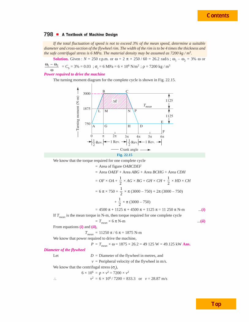
Power required to drive the machineThe turning moment diagram for the complete cycle is shown in Fig. 22.15.
Fig. 22.15
We know that the torque required for one complete cycle
= Area of figure OABCDEF
= Area OAEF + Area ABG + Area BCHG + Area CDH
= OF × OA + 12
× AG × BG + GH × CH + 12
× HD × CH
= 6 π × 750 + 12
× π (3000 – 750) + 2π (3000 – 750)
+ 12
× π (3000 – 750)
= 4500 π + 1125 π + 4500 π + 1125 π = 11 250 π N-m ...(i)If Tmean is the mean torque in N-m, then torque required for one complete cycle
= Tmean × 6 π N-m ...(ii)From equations (i) and (ii),
Tmean = 11250 π / 6 π = 1875 N-m
We know that power required to drive the machine,
P = Tmean × ω = 1875 × 26.2 = 49 125 W = 49.125 kW Ans.Diameter of the flywheel
Let D = Diameter of the flywheel in metres, and
v = Peripheral velocity of the flywheel in m/s.
We know that the centrifugal stress (σt),
6 × 106 = ρ × v2 = 7200 × v2
∴ v2 = 6 × 10⁶ / 7200 = 833.3 or v = 28.87 m/s
Flywheel 799We also know that peripheral velocity of the flywheel (v),
28.87 = 250
60 60D N Dπ π ×= = 13.1 D
∴ D = 28.87 / 13.1 = 2.2 m Ans.
Cross-section of the flywheel rim
Let t = Thickness of the flywheel rim in metres, and
b = Width of the flywheel rim in metres = 4 t ...(Given)
∴ Cross-sectional area of the flywheel rim,
A = b × t = 4 t × t = 4 t2 m2
First of all, let us find the maximum fluctuation of energy (Δ E) and mass of the flywheel rim(m). In order to find ΔE, we shall calculate the values of LM and NP.
From similar triangles ABG and BLM,
LM BMAG BG
= orLMπ =
3000 18573000 750
−− = 0.5 or LM = 0.5 π
Now from similar triangles CHD and CNP,
NP CNHD CH
= or 3000 18753000 750
NP −=π − = 0.5 or NP = 0.5 π
From Fig. 22.15, we find that
BM = CN = 3000 – 1875 = 1125 N-m
Since the area above the mean torque line represents the maximum fluctuation of energy,therefore maximum fluctuation of energy,
Δ E = Area LBCP = Area LBM + Area MBCN + Area PNC
=12
× LM × BM + MN × BM + 12
× NP × CN
=12
× 0.5 π × 1125 + 2 π × 1125 + 12
× 0.5 π × 1125
= 8837 N-m
We know that maximum fluctuation of energy (ΔE),
8837 = m.R2.ω2.CS = m 2
2.22
⎛ ⎞⎜ ⎟⎝ ⎠
(26.2)2 0.03 = 24.9 m
∴ m = 8837 / 24.9 = 355 kg
We also know that mass of the flywheel rim (m),
355 = A × π D × ρ = 4 t2 × π × 2.2 × 7200 = 199 077 t2
∴ t2 = 355 / 199 077 = 0.00178 or t = 0.042 m = 42 say 45 mm Ans.
and b = 4 t = 4 × 45 = 180 mm Ans.
Example 22.9. A punching machine makes 25 working strokes per minute and is capable ofpunching 25 mm diameter holes in 18 mm thick steel plates having an ultimate shear strength of300 MPa.
The punching operation takes place during 1/10 th of a revolution of the crank shaft.
Estimate the power needed for the driving motor, assuming a mechanical efficiency of 95 percent. Determine suitable dimensions for the rim cross-section of the flywheel, which is to revolve at9 times the speed of the crank shaft. The permissible coefficient of fluctuation of speed is 0.1.

800 A Textbook of Machine Design
The flywheel is to be made of cast iron having a working stress (tensile) of 6 MPa and densityof 7250 kg / m3. The diameter of the flywheel must not exceed 1.4 m owing to space restrictions. Thehub and the spokes may be assumed to provide 5% of the rotational inertia of the wheel.
Check for the centrifugal stress induced in the rim.
Solution. Given : n = 25 ; d1 = 25 mm ; t1 = 18 mm ; τu = 300 MPa = 300 N/mm2 ;ηm = 95% = 0.95 ; CS = 0.1 ; σt = 6 MPa = 6 N/mm2 ; ρ = 7250 kg/m3 ; D = 1.4 m or R = 0.7m
Power needed for the driving motor
We know that the area of plate sheared,AS = π d1 × t1 = π × 25 × 18 = 1414 mm2
∴ Maximum shearing force required for punching,FS = AS × τu = 1414 × 300 = 424 200 N
and energy required per stroke= *Average shear force × Thickness of plate
=12
FS × t1 = 12
× 424 200 × 18 = 3817.8 × 103 N-mm
∴ Energy required per min= Energy / stroke × No. of working strokes / min= 3817.8 × 103 × 25 = 95.45 × 10⁶ N-mm = 95 450 N-m
We know that the power needed for the driving motor
= Energy required per min
60 m× η = 95 450
60 0.95× = 1675 W
= 1.675 kW Ans.
* As the hole is punched, it is assumed that the shearing force decreases uniformly from maximum valueto zero.
Punching Machine
Flywheel 801Dimensions for the rim cross-section
Considering the cross-section of the rim as rectangular and assuming the width of rim equal totwice the thickness of rim.
Let t = Thickness of rim in metres, andb = Width of rim in metres = 2 t.
∴ Cross-sectional area of rim,A = b × t = 2 t × t = 2 t2
Since the punching operation takes place (i.e. energy is consumed) during 1/10 th of a revolutionof the crank shaft, therefore during 9/10 th of the revolution of a crank shaft, the energy is stored in theflywheel.
∴ Maximum fluctuation of energy,
Δ E = 9
10 × Energy/stroke =
910
× 3817.8 × 103
= 3436 × 103 N-mm = 3436 N-mLet m = Mass of the flywheel.Since the hub and the spokes provide 5% of the rotational inertia of the wheel, therefore the
maximum fluctuation of energy provided by the flywheel rim will be 95%.∴ Maximum fluctuation of energy provided by the rim,
(Δ E)rim = 0.95 × Δ E = 0.95 × 3436 = 3264 N-mSince the flywheel is to revolve at 9 times the speed of the crankshaft and there are 25 working
strokes per minute, therefore mean speed of the flywheel,N = 9 × 25 = 225 r.p.m.
and mean angular speed, ω = 2 π × 225 / 60 = 23.56 rad/sWe know that maximum fluctuation of energy (Δ E),
3264 = m.R2.ω2.CS = m (0.7)2 (23.56)2 0.1 = 27.2 m
∴ m = 3264 / 27.2 = 120 kg
We also know that mass of the flywheel (m),
120 = A × π D × ρ = 2 t2 × π × 1.4 × 7250 = 63 782 t2
∴ t 2 = 120 / 63 782 = 0.001 88 or t = 0.044 m = 44 mm Ans.and b = 2 t = 2 × 44 = 88 mm Ans.Check for centrifugal stress
We know that peripheral velocity of the rim,
v = . 1.4 225
60 60D Nπ π × ×= = 16.5 m/s
∴ Centrifugal stress induced in the rim,
σt = ρ.v2 = 7250 (16.5)2 = 1.97 × 10⁶ N/m2 = 1.97 MPa
Since the centrifugal stress induced in the rim is less than the permissible value (i.e. 6 MPa),therefore it is safe Ans.
22.8 Stresses in Flywheel ArmsThe following stresses are induced in the arms of a flywheel.
1. Tensile stress due to centrifugal force acting on the rim.
2. Bending stress due to the torque transmitted from the rim to the shaft or from the shaft to the rim.
3. Shrinkage stresses due to unequal rate of cooling of casting. These stresses are difficult todetermine.
802 A Textbook of Machine Design
We shall now discuss the first two types of stresses as follows:1. Tensile stress due to the centrifugal force
Due to the centrifugal force acting on the rim, the arms will be subjected to direct tensile stresswhose magnitude is same as discussed in the previous article.
∴ Tensile stress in the arms,
σt1 = 34
σt = 34
ρ × v2
2. Bending stress due to the torque transmittedDue to the torque transmitted from the rim
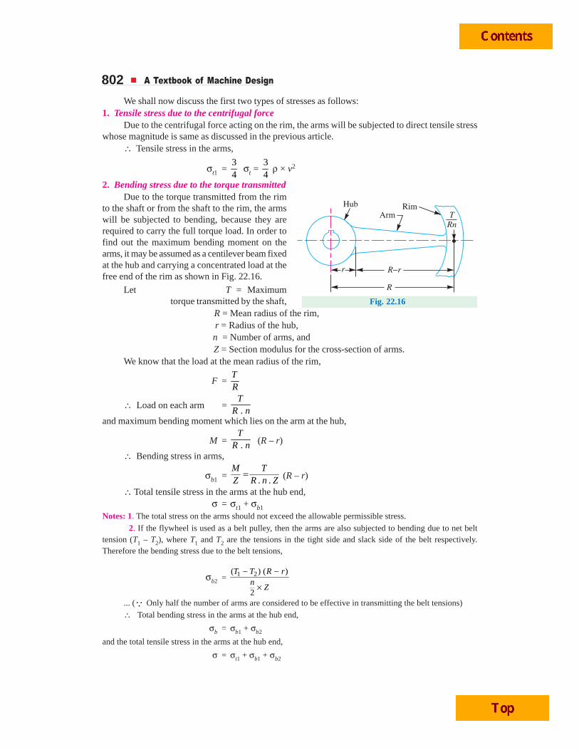
to the shaft or from the shaft to the rim, the armswill be subjected to bending, because they arerequired to carry the full torque load. In order tofind out the maximum bending moment on thearms, it may be assumed as a centilever beam fixedat the hub and carrying a concentrated load at thefree end of the rim as shown in Fig. 22.16.
Let T = Maximumtorque transmitted by the shaft,
R = Mean radius of the rim, r = Radius of the hub, n = Number of arms, and
Z = Section modulus for the cross-section of arms.We know that the load at the mean radius of the rim,
F = TR
∴ Load on each arm = .
TR n
and maximum bending moment which lies on the arm at the hub,
M = .T
R n (R – r)
∴ Bending stress in arms,
σb1 = . .=M T
Z R n Z (R – r)
∴ Total tensile stress in the arms at the hub end,σ = σt1 + σb1
Notes: 1. The total stress on the arms should not exceed the allowable permissible stress.
2. If the flywheel is used as a belt pulley, then the arms are also subjected to bending due to net belttension (T1 – T2), where T1 and T2 are the tensions in the tight side and slack side of the belt respectively.Therefore the bending stress due to the belt tensions,
σb2 = 1 2( ) ( )
2
− −
×
T T R rn
Z
... (Q Only half the number of arms are considered to be effective in transmitting the belt tensions)
∴ Total bending stress in the arms at the hub end,
σb = σb1 + σb2
and the total tensile stress in the arms at the hub end,
σ = σt1 + σb1 + σb2
Fig. 22.16
Flywheel 803
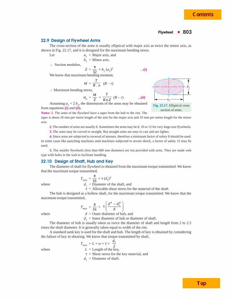
22.9 Design of Flywheel ArmsThe cross-section of the arms is usually elliptical with major axis as twice the minor axis, as
shown in Fig. 22.17, and it is designed for the maximum bending stress.Let a1 = Major axis, and
b1 = Minor axis.∴ Section modulus,
Z = 32π
× b1 (a1)2 ...(i)
We know that maximum bending moment,
M = .T
R n (R – r)
∴ Maximum bending stress,
σb = MZ
= . .
T
R n Z (R – r) ...(ii)
Assuming a1 = 2 b1, the dimensions of the arms may be obtainedfrom equations (i) and (ii).Notes: 1. The arms of the flywheel have a taper from the hub to the rim. Thetaper is about 20 mm per metre length of the arm for the major axis and 10 mm per metre length for the minoraxis.
2. The number of arms are usually 6. Sometimes the arms may be 8, 10 or 12 for very large size flywheels.
3. The arms may be curved or straight. But straight arms are easy to cast and are lighter.
4. Since arms are subjected to reversal of stresses, therefore a minimum factor of safety 8 should be used.In some cases like punching machines amd machines subjected to severe shock, a factor of safety 15 may beused.
5. The smaller flywheels (less than 600 mm diameter) are not provided with arms. They are made webtype with holes in the web to facilitate handling.
22.10 Design of Shaft, Hub and KeyThe diameter of shaft for flywheel is obtained from the maximum torque transmitted. We know
that the maximum torque transmitted,
Tmax = 16π
× τ (d1)3
where d1 = Diameter of the shaft, andτ = Allowable shear stress for the material of the shaft.
The hub is designed as a hollow shaft, for the maximum torque transmitted. We know that themaximum torque transmitted,
Tmax = 16π
× 4 4
1d dd
⎛ ⎞−τ ⎜ ⎟⎜ ⎟⎝ ⎠
where d = Outer diameter of hub, andd1 = Inner diameter of hub or diameter of shaft.
The diameter of hub is usually taken as twice the diameter of shaft and length from 2 to 2.5times the shaft diameter. It is generally taken equal to width of the rim.
A standard sunk key is used for the shaft and hub. The length of key is obtained by consideringthe failure of key in shearing. We know that torque transmitted by shaft,
Tmax = L × w × τ × 1
2
d
where L = Length of the key,τ = Shear stress for the key material, and
d1 = Diameter of shaft.
Fig. 22.17. Elliptical crosssection of arms.
804 A Textbook of Machine Design
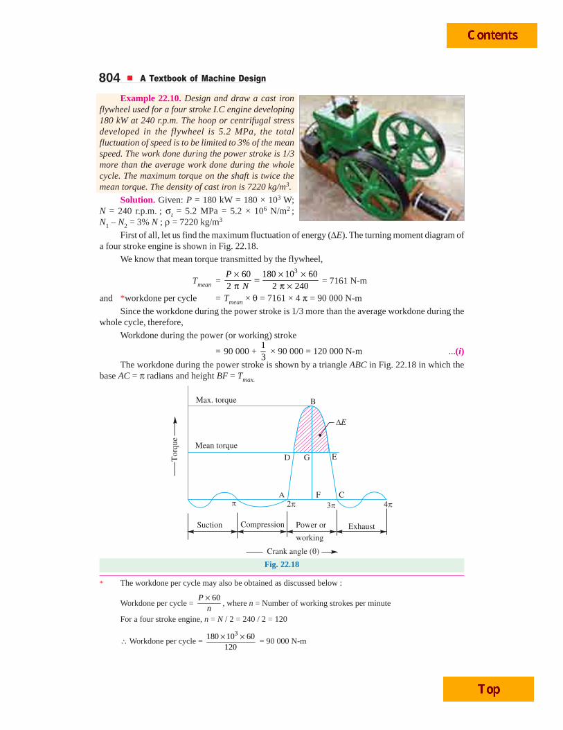
Example 22.10. Design and draw a cast ironflywheel used for a four stroke I.C engine developing180 kW at 240 r.p.m. The hoop or centrifugal stressdeveloped in the flywheel is 5.2 MPa, the totalfluctuation of speed is to be limited to 3% of the meanspeed. The work done during the power stroke is 1/3more than the average work done during the wholecycle. The maximum torque on the shaft is twice themean torque. The density of cast iron is 7220 kg/m3.
Solution. Given: P = 180 kW = 180 × 103 W;N = 240 r.p.m. ; σt = 5.2 MPa = 5.2 × 10⁶ N/m2 ;N1 – N2 = 3% N ; ρ = 7220 kg/m3
First of all, let us find the maximum fluctuation of energy (ΔE). The turning moment diagram ofa four stroke engine is shown in Fig. 22.18.
We know that mean torque transmitted by the flywheel,
Tmean = 360 180 10 60
2 2 240P
N× × ×=π π × = 7161 N-m
and *workdone per cycle = Tmean × θ = 7161 × 4 π = 90 000 N-m
Since the workdone during the power stroke is 1/3 more than the average workdone during thewhole cycle, therefore,
Workdone during the power (or working) stroke
= 90 000 + 13
× 90 000 = 120 000 N-m ...(i)
The workdone during the power stroke is shown by a triangle ABC in Fig. 22.18 in which thebase AC = π radians and height BF = Tmax.
Fig. 22.18
* The workdone per cycle may also be obtained as discussed below :
Workdone per cycle = 60×P
n, where n = Number of working strokes per minute
For a four stroke engine, n = N / 2 = 240 / 2 = 120
∴ Workdone per cycle = 3180 10 60
120× ×
= 90 000 N-m
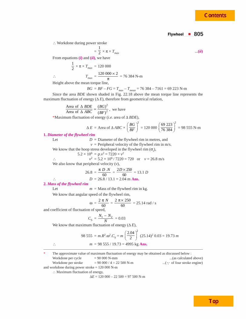
Flywheel 805∴ Workdone during power stroke
= 12 × π × Tmax ...(ii)
From equations (i) and (ii), we have12
× π × Tmax = 120 000
∴ Tmax = 120 000 2×
π = 76 384 N-m
Height above the mean torque line,
BG = BF – FG = Tmax – Tmean = 76 384 – 7161 = 69 223 N-m
Since the area BDE shown shaded in Fig. 22.18 above the mean torque line represents themaximum fluctuation of energy (Δ E), therefore from geometrical relation,
2
2
Area of ( )Area of ( )
BDE BGABC BF
Δ =Δ , we have
*Maximum fluctuation of energy (i.e. area of Δ BDE),
Δ E = Area of Δ ABC × 2
BGBF
⎛ ⎞⎜ ⎟⎝ ⎠
= 120 000 2
69 22376 384
⎛ ⎞⎜ ⎟⎝ ⎠
= 98 555 N-m
1. Diameter of the flywheel rimLet D = Diameter of the flywheel rim in metres, and
v = Peripheral velocity of the flywheel rim in m/s.We know that the hoop stress developed in the flywheel rim (σt),
5.2 × 106 = ρ.v2 = 7220 × v2
∴ v2 = 5.2 × 10⁶ / 7220 = 720 or v = 26.8 m/sWe also know that peripheral velocity (v),
26.8 = .
60D Nπ
= 2 250
60D ×
= 13.1 D
∴ D = 26.8 / 13.1 = 2.04 m Ans.2. Mass of the flywheel rim
Let m = Mass of the flywheel rim in kg.
We know that angular speed of the flywheel rim,
ω = 2
60Nπ
= 2 250
60π ×
= 25.14 rad / s
and coefficient of fluctuation of speed,
CS = 1 2N NN−
= 0.03
We know that maximum fluctuation of energy (Δ E),
98 555 = m.R2.ω2.CS = m 2
2.042
⎛ ⎞⎜ ⎟⎝ ⎠
(25.14)2 0.03 = 19.73 m
∴ m = 98 555 / 19.73 = 4995 kg Ans.
* The approximate value of maximum fluctuation of energy may be obtained as discussed below :Workdone per cycle = 90 000 N-mm ...(as calculated above)Workdone per stroke = 90 000 / 4 = 22 500 N-m ...(Q of four stroke engine)
and workdone during power stroke = 120 000 N-m∴ Maximum fluctuation of energy,
ΔE = 120 000 – 22 500 = 97 500 N-m
806 A Textbook of Machine Design
3. Cross-sectional dimensions of the rim
Let t = Depth or thickness of the rim in metres, and
b = Width of the rim in metres = 2 t ...(Assume)
∴ Cross-sectional area of the rim,
A = b.t = 2 t × t = 2 t2
We know that mass of the flywheel rim (m),
4995 = A × πD × ρ = 2 t2 × π × 2.04 × 7220 = 92 556 t2
∴ t2 = 4995 / 92 556 = 0.054 or t = 0.232 say 0.235 m = 235 mm Ans.and b = 2 t = 2 × 235 = 470 mm Ans.4. Diameter and length of hub
Let d = Diameter of the hub,
d1 = Diameter of the shaft, and
l = Length of the hub.
Since the maximum torque on the shaft is twice the mean torque, therefore maximum torqueacting on the shaft,
Tmax = 2 × Tmean = 2 × 7161 = 14 322 N-m = 14 322 × 103 N-mm
We know that the maximum torque acting on the shaft (Tmax),
14 322 × 103 = 16π
× τ (d1)3 = 16π
× 40 (d1)3 = 7.855 (d1)
3
...(Taking τ = 40 MPa = 40 N/mm2)
∴ (d1)3 = 14 322 × 103 / 7.855 = 1823 × 103
or d1 = 122 say 125 m Ans.The diameter of the hub is made equal to twice the diameter of shaft and length of hub is equal
to width of the rim.
∴ d = 2 d1 = 2 × 125 = 250 mm = 0.25 m
and l = b = 470 mm = 0.47 mm Ans.
5. Cross-sectional dimensions of the elliptical arms
Let a1 = Major axis,
b1 = Minor axis = 0.5 a1 ...(Assume)
n = Number of arms = 6 ...(Assume)
σb = Bending stress for the material of arms = 15 MPa = 15 N/mm2
...(Assume)We know that the maximum bending moment in the arm at the hub end, which is assumed as
cantilever is given by
M = .
T
R n (R – r) = .T
D n (D – d) = 14 3222.04 6× (2.04 – 0.25) N-m
= 2094.5 N-m = 2094.5 × 103 N-mm
and section modulus for the cross-section of the arm,
Z = 32π
× b1 (a1)2 =
32π
× 0.5 a1 (a1)2 = 0.05 (a1)3
Flywheel 807We know that the bending stress (σb),
15 = 3
31
2094.5 10
0.05( )
×=MZ a
= 3
31
41 890 10
( )a
×
∴ (a1)3 = 41 890 × 103 / 15 = 2793 × 103 or a1 = 140 mm Ans.
and b1 = 0.5 a1 = 0.5 × 140 = 70 mm Ans.6. Dimensions of key
The standard dimensions of rectangular sunk key for a shaft of diameter 125 mm are as follows:
Width of key, w = 36 mm Ans.and thickness of key = 20 mm Ans.
The length of key (L) is obtained by considering the failure of key in shearing.
We know that the maximum torque transmitted by the shaft (Tmax),
14 322 × 103 = L × w × τ × 1
2
d = L × 36 × 40 ×
1252
= 90 × 103 L
∴ L = 14 322 × 103 / 90 × 103 = 159 say 160 mm Ans.Let us now check the total stress in the rim which should not be greater than 15 MPa. We know
that total stress in the rim,
σ = ρ.v2 2
4.9350.75
.
R
n t
⎛ ⎞+⎜ ⎟⎜ ⎟
⎝ ⎠
= 7220 (26.8)22
4.935 (2.04 / 2)0.75
6 0.235
⎡ ⎤+⎢ ⎥
×⎣ ⎦ N/m2
= 5.18 × 10⁶ (0.75 + 0.595) = 6.97 × 10⁶ N/m2 = 6.97 MPa
Since it is less than 15 MPa, therefore the design is safe.
Example 22.11. A single cylinder double acting steam engine delivers 185 kW at 100 r.p.m.The maximum fluctuation of energy per revolution is 15 per cent of the energy developed per revolution.The speed variation is limited to 1 per cent either way from the mean. The mean diameter of the rimis 2.4 m. Design and draw two views of the flywheel.
Solution. Given : P = 185 kW = 185 × 103 W ; N = 100 r.p.m ; Δ E = 15% E = 0.15 E ;D = 2.4 m or R = 1.2 m
1. Mass of the flywheel rimLet m = Mass of the flywheel rim in kg.
We know that the workdone or energy developed per revolution,
E = 60P
N×
= 3185 10 60
100× ×
= 111 000 N-m
∴ Maximum fluctuation of energy,
Δ E = 0.15 E = 0.15 × 111 000 = 16 650 N-m
Since the speed variation is 1% either way from the mean, therefore the total fluctuation ofspeed,
N1 – N2 = 2% of mean speed = 0.02 N
and coefficient of fluctuation of speed,
CS = 1 2N NN−
= 0.02
808 A Textbook of Machine Design
Velocity of the flywheel,
v = .
60π D N
= 2.4 10060
π × × = 12.57 m/s
We know that the maximum fluctuation of energy (Δ E),
16 650 = m.v2.CS = m (12.57)2 0.02 = 3.16 m
∴ m = 16 650 / 3.16 = 5270 kg Ans.2. Cross-sectional dimensions of the flywheel rim
Let t = Thickness of the flywheel rim in metres, and
b = Width of the flywheel rim in metres = 2 t ...(Assume)
∴ Cross-sectional area of the rim,
A = b × t = 2 t × t = 2 t2
We know that mass of the flywheel rim (m),
5270 = A × π D × ρ = 2 t2 × π × 2.4 × 7200 = 108 588 t2
...(Taking ρ = 7200 kg / m3)
∴ t 2 = 5270 / 108 588 = 0.0485 or t = 0.22 m = 220 mm Ans.and b = 2 t = 2 × 220 = 440 mm Ans.3. Diameter and length of hub
Let d = Diameter of the hub,
d1 = Diameter of the shaft, and
l = Length of the hub,
Steam engine in a Laboratory
Flywheel 809We know that mean torque transmitted by the shaft,
Tmean = 360 185 10 60
2 2 100P
N× × ×=π π × = 17 664 N-m
Assuming that the maximum torque transmitted (Tmax) by the shaft is twice the mean torque,therefore
Tmax = 2 × Tmean = 2 × 17 664 = 35 328 N-m = 35.328 × 10⁶ N-mm
We also know that maximum torque transmitted by the shaft (Tmax),
35.328 × 106 = 31( )
16d
π × τ = 3140 ( )
16d
π × = 7.855 (d1)3
...(Assuming τ = 40 MPa = 40 N/mm2)
∴ (d1)3 = 35.328 × 10⁶ / 7.855 = 4.5 × 10⁶ or d1 = 165 mm Ans.
The diameter of the hub (d) is made equal to twice the diameter of the shaft (d1) and length ofthe hub (l ) is equal to the width of the rim (b).
∴ d = 2 d1 = 2 × 165 = 330 mm ; and l = b = 440 mm Ans.4. Cross-sectional dimensions of the elliptical arms
Let a1 = Major axis,
b1 = Minor axis = 0.5 a1 ...(Assume)
n = Number of arms = 6 ...(Assume)
σb = Bending stress for the material of the arms
= 14 MPa = 14 N/mm2 ...(Assume)
We know that the maximum bending moment in the arm at the hub end which is assumed ascantilever is given by
M = .
T
R n (R – r) = .
TD n (D – d ) =
35 328
2.4 6× (2.4 – 0.33) N-m
= 5078 N-m = 5078 × 103 N-mm ...(d is taken in metres)
and section modulus for the cross-section of the arm,
Z = 32π
b1 (a1)2 =
32π
× 0.5 a1 (a1)2 = 0.05 (a1)
3
We know that the bending stress (σb),
14 = MZ
= 3 3
3 31 1
5078 10 101 560 10
0.05 ( ) ( )a a
× ×=
∴ (a1)3 = 101 560 × 103 / 14 = 7254 × 103
or a1 = 193.6 say 200 mm Ans.and b1 = 0.5 a1 = 0.5 × 200 = 100 mm Ans.5. Dimensions of key
The standard dimensions of rectangular sunk key for a shaft of 165 mm diameter are as follows:Width of key, w = 45 mm Ans.
and thickness of key = 25 mm Ans.The length of key (L) is obtained by considering the failure of key in shearing.
We know that the maximum torque transmitted by the shaft (Tmax),
35.328 × 106 = L × w × τ × 1
2d
= L × 45 × 40 × 165
2 = 148 500 L
∴ L = 35.328 × 10⁶ / 148 500 = 238 mm Ans.
810 A Textbook of Machine Design
Let us now check the total stress in the rim which should not be greater than 14 MPa. We knowthat the total stress in the rim,
= ρ.v2 2
4.9350.75
.
⎛ ⎞+⎜ ⎟⎜ ⎟
⎝ ⎠
R
n t
= 7200 (12.57)2 2
4.935 1.20.75
6 0.22
⎡ ⎤×+⎢ ⎥×⎣ ⎦
N/m2
= 1.14 × 10⁶ (0.75 + 0.75) = 1.71 × 10⁶ N/m2 = 1.71 MPa
Since it is less than 14 MPa, therefore the design is safe.
Example 22.12. A punching press pierces 35 holes per minute in a plate using 10 kN-m ofenergy per hole during each revolution. Each piercing takes 40 per cent of the time needed to makeone revolution. The punch receives power through a gear reduction unit which in turn is fed by amotor driven belt pulley 800 mm diameter and turning at 210 r.p.m. Find the power of the electricmotor if overall efficiency of the transmission unit is 80 per cent. Design a cast iron flywheel to beused with the punching machine for a coefficient of steadiness of 5, if the space considerations limitthe maximum diameter to 1.3 m.
Allowable shear stress in the shaft material = 50 MPa
Allowable tensile stress for cast iron = 4 MPa
Density of cast iron = 7200 kg / m3
Solution. Given : No. of holes = 35 per min ; Energy per hole = 10 kN-m = 10 000 N-m ;d = 800 mm = 0.8 m ; N = 210 r.p.m. ; η = 80% = 0.8 ; 1/CS = 5 or CS = 1/5 = 0.2 ; Dmax = 1.3 m ;τ = 50 MPa = 50 N/mm2 ; σt = 4 MPa = 4 N/mm2 ; ρ = 7200 kg / m3
Power of the electric motorWe know that energy used for piercing holes per minute
= No. of holes pierced × Energy used per hole= 35 × 10 000 = 350 000 N-m / min
∴ Power needed for the electric motor,
P = Energy used per minute
60 × η = 350 00060 0.8× = 7292 W = 7.292 kW Ans.
Design of cast iron flywheelFirst of all, let us find the maximum fluctuation of energy.Since the overall efficiency of the transmission unit is 80%, therefore total energy to be supplied
during each revolution,
ET = 10 000
0.8 = 12 500 N-m
We know that velocity of the belt,v = π d.N = π × 0.8 × 210 = 528 m/min
∴ Net tension or pull acting on the belt
= 60P
v×
= 7292 60
528×
= 828.6 N
Since each piercing takes 40 per cent of the time needed to make one revolution, therefore timerequired to punch a hole
= 0.4 / 35 = 0.0114 minand the distance moved by the belt during punching a hole
= Velocity of the belt × Time required to punch a hole
= 528 × 0.0114 = 6.03 m
Flywheel 811∴ Energy supplied by the belt during punching a hole,
EB = Net tension × Distance travelled by belt
= 828.6 × 6.03 = 4996 N-m
Thus energy to be supplied by the flywheel for punching during each revolution or maximumfluctuation of energy,
Δ E = ET – EB = 12 500 – 4996 = 7504 N-m
1. Mass of the flywheelLet m = Mass of the flywheel rim.
Since space considerations limit the maximum diameter of the flywheel as 1.3 m ; therefore letus take the mean diameter of the flywheel,
D = 1.2 m or R = 0.6 m
We know that angular velocity
ω = 2
60Nπ ×
= 2 210
60π ×
= 22 rad / s
We also know that the maximum fluctuation of energy (Δ E),7504 = m.R2.ω2.CS = m (0.6)2 (22)2 0.2 = 34.85 m
∴ m = 7504 / 34.85 = 215.3 kg Ans.2. Cross-sectional dimensions of the flywheel rim
Let t = Thickness of the flywheel rim in metres, and
b = Width of the flywheel rim in metres = 2 t ...(Assume)
∴ Cross-sectional area of the rim,
A = b × t = 2 t × t = 2 t 2
We know that mass of the flywheel rim (m),
215.3 = A × π D × ρ = 2 t2 × π × 1.2 × 7200 = 54.3 × 10³ t2
∴ t 2 = 215.3 / 54.3 × 103 = 0.003 96
or t = 0.063 say 0.065 m = 65 mm Ans.and b = 2 t = 2 × 65 = 130 mm Ans3. Diameter and length of hub
Let d = Diameter of the hub,d1 = Diameter of the shaft, and
l = Length of the hub.First of all, let us find the diameter of the shaft (d1). We know that the mean torque transmitted
by the shaft,
Tmean = 60
2P
N×π =
7292 602 210
×π × = 331.5 N-m
Assuming that the maximum torque transmitted by the shaft is twice the mean torque, thereforemaximum torque transmitted by the shaft,
Tmax = 2 × Tmean = 2 × 331.5 = 663 N-m = 663 × 103 N-mm
We know that maximum torque transmitted by the shaft (Tmax),
663 × 103 = 16π
× τ (d1)3 =
16π
× 50 (d1)3 = 9.82 (d1)3
∴ (d1)3 = 663 × 103 / 9.82 = 67.5 × 10³
or d1 = 40.7 say 45 mm Ans.
812 A Textbook of Machine Design
The diameter of the hub (d ) is made equal to twice the diameter of the shaft (d1) and length ofhub ( l ) is equal to the width of the rim (b).
∴ d = 2 d1 = 2 × 45 = 90 mm = 0.09 m and l = b = 130 mm Ans.4. Cross-sectional dimensions of the elliptical cast iron arms
Let a1 = Major axis,b1 = Minor axis = 0.5 a1 ...(Assume)
n = Number of arms = 6 ... (Assume)
We know that the maximum bending moment in the arm at the hub end, which is assumed ascantilever is given by
M = .
TR n
(R – r) = .
T
D n (D – d) =
663
1.2 6× (1.2 – 0.09) N-m
= 102.2 N-m = 102 200 N-mmand section modulus for the cross-section of the arms,
Z = 32π
× b1 (a1)2 =
32π
× 0.5 a1 (a1)2 = 0.05 (a1)3
We know that bending stress (σt),
4 = MZ
= 3
3 31 1
102 200 2044 10
0.05 ( ) ( )a a
×=
∴ (a1)3 = 2044 × 103 / 4 = 511 × 103 or a1 = 80 mm Ans.
and b1 = 0.5 a1 = 0.5 × 80 = 40 mm Ans.5. Dimensions of key
The standard dimensions of rectangular sunk key for a shaft of diameter 45 mm are as follows:Width of key, w = 16 mm Ans.
and thickness of key = 10 mm Ans.The length of key (L) is obtained by considering the failure of key in shearing.We know that maximum torque transmitted by the shaft (Tmax),
663 × 103 = L × w × τ × 1
2d
= L × 16 × 50 × 452
= 18 × 103 L
∴ L = 663 × 103/18 × 103 = 36.8 say 38 mm Ans.Let us now check the total stress in the rim which should not be greater than 4 MPa.We know that the velocity of the rim,
v = 1.2 210
13.2m/ s60 60
π × π × ×= =D N
∴ Total stress in the rim,
σ = ρ.v2 2
4.9350.75
.
R
n t
⎛ ⎞+⎜ ⎟⎜ ⎟
⎝ ⎠ = 7200 (13.2)2
2
4.935 0.60.75
6 0.065
⎡ ⎤×+⎢ ⎥×⎣ ⎦
= 1.25 × 10⁶ (0.75 + 1.26) = 2.5 × 10⁶ N/m2 = 2.5 MPaSince it is less than 4 MPa, therefore the design is safe.
22.11 Construction of FlywheelsThe flywheels of smaller size (upto 600 mm diameter) are casted in one piece. The rim and hub
are joined together by means of web as shown in Fig. 22.19 (a). The holes in the web may be made forhandling purposes.
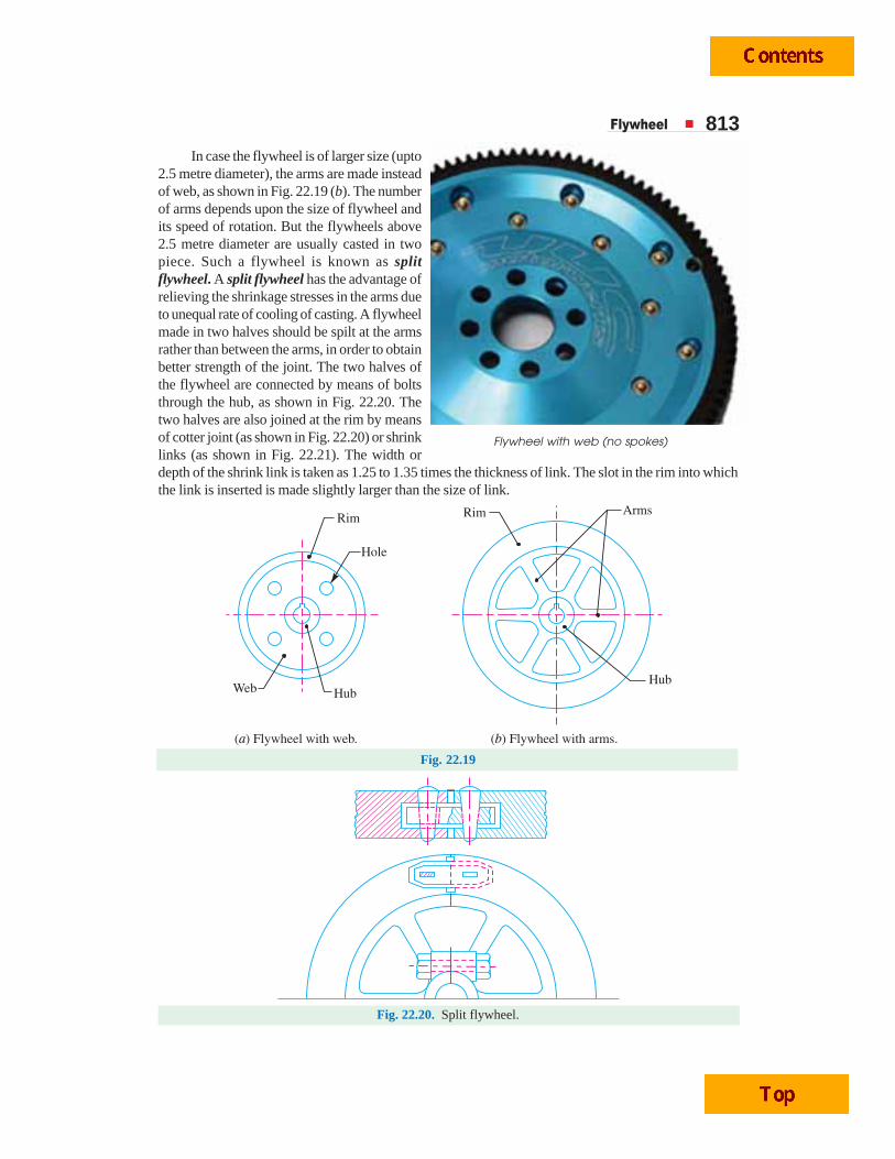
Flywheel 813In case the flywheel is of larger size (upto
2.5 metre diameter), the arms are made insteadof web, as shown in Fig. 22.19 (b). The numberof arms depends upon the size of flywheel andits speed of rotation. But the flywheels above2.5 metre diameter are usually casted in twopiece. Such a flywheel is known as splitflywheel. A split flywheel has the advantage ofrelieving the shrinkage stresses in the arms dueto unequal rate of cooling of casting. A flywheelmade in two halves should be spilt at the armsrather than between the arms, in order to obtainbetter strength of the joint. The two halves ofthe flywheel are connected by means of boltsthrough the hub, as shown in Fig. 22.20. Thetwo halves are also joined at the rim by meansof cotter joint (as shown in Fig. 22.20) or shrinklinks (as shown in Fig. 22.21). The width ordepth of the shrink link is taken as 1.25 to 1.35 times the thickness of link. The slot in the rim into whichthe link is inserted is made slightly larger than the size of link.
Fig. 22.19
Fig. 22.20. Split flywheel.
Flywheel with web (no spokes)
814 A Textbook of Machine Design
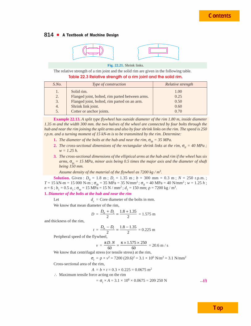
Fig. 22.21. Shrink links.
The relative strength of a rim joint and the solid rim are given in the following table.
Table 22.3 Relative strength of a rim joint and the solid rim.
S.No. Type of construction Relative strength
1. Solid rim. 1.002. Flanged joint, bolted, rim parted between arms. 0.253. Flanged joint, bolted, rim parted on an arm. 0.504. Shrink link joint. 0.605. Cotter or anchor joints. 0.70
Example 22.13. A split type flywheel has outside diameter of the rim 1.80 m, inside diameter1.35 m and the width 300 mm. the two halves of the wheel are connected by four bolts through thehub and near the rim joining the split arms and also by four shrink links on the rim. The speed is 250r.p.m. and a turning moment of 15 kN-m is to be transmitted by the rim. Determine:
1. The diameter of the bolts at the hub and near the rim, σtb = 35 MPa.
2. The cross-sectional dimensions of the rectangular shrink links at the rim, σtl = 40 MPa ;w = 1.25 h.
3. The cross-sectional dimensions of the elliptical arms at the hub and rim if the wheel has sixarms, σta = 15 MPa, minor axis being 0.5 times the major axis and the diameter of shaftbeing 150 mm.
Assume density of the material of the flywheel as 7200 kg / m3.
Solution. Given : D0 = 1.8 m ; Di = 1.35 m ; b = 300 mm = 0.3 m ; N = 250 r.p.m. ;T = 15 kN-m = 15 000 N-m ; σtb = 35 MPa = 35 N/mm2 ; σtl = 40 MPa = 40 N/mm2 ; w = 1.25 h ;n = 6 ; b1 = 0.5 a1 ; σta = 15 MPa = 15 N / mm2 ; d1 = 150 mm; ρ = 7200 kg / m3.
1. Diameter of the bolts at the hub and near the rimLet dc = Core diameter of the bolts in mm.
We know that mean diameter of the rim,
D = 1.8 1.35
2 2o iD D+ += = 1.575 m
and thickness of the rim,
t = 1.8 1.35
2 2o iD D− −= = 0.225 m
Peripheral speed of the flywheel,
v = . 1.575 250
60 60D Nπ π × ×= = 20.6 m / s
We know that centrifugal stress (or tensile stress) at the rim,
σt = ρ × v2 = 7200 (20.6)2 = 3.1 × 10⁶ N/m2 = 3.1 N/mm2
Cross-sectional area of the rim,
A = b × t = 0.3 × 0.225 = 0.0675 m2
∴ Maximum tensile force acting on the rim
= σt × A = 3.1 × 106 × 0.0675 = 209 250 N ...(i)
Flywheel 815We know that tensile strength of the four bolts
= 4π
(dc)2 σtb × No. of bolts =
4π
(dc)2 35 × 4 = 110 (dc)
2 ...(ii)
Since the bolts are made as strong as the rim joint, therefore from equations (i) and (ii), we have
(dc )2 = 209 250 / 110 = 1903 or dc = 43.6 mm
The standard size of the bolt is M 56 with dc = 48.65 mm Ans.2. Cross-sectional dimensions of rectangular shrink links at the rim
Let h = Depth of the link in mm, and
w = Width of the link in mm = 1.25 h ...(Given)
∴ Cross-sectional area of each link,
Al = w × h = 1.25 h2 mm2
We know that the maximum tensile force on half the rim
= 2 × σt for rim × Cross-sectional area of rim
= 2 × 3.1 × 106 × 0.0675 = 418 500 N ...(iii)and tensile strength of the four shrink links
= σtl × Al × 4 = 40 × 1.25 h2 × 4 = 200 h2 ...(iv)From equations (iii) and (iv), we have
h2 = 418 500 / 200 = 2092.5 or h = 45.7 say 46 mm Ans.and w = 1.25 h = 1.25 × 46 = 57.5 say 58 mm Ans.3. Cross-sectional dimensions of the elliptical arms
Let a1 = Major axis,b1 = Minor axis = 0.5 a1 ...(Given)
n = Number of arms = 6 ...(Given)
Since the diameter of shaft (d1) is 150 mm and the diameter of hub (d ) is taken equal to twicethe diameter of shaft, therefore
d = 2 d1 = 2 × 150 = 300 mm = 0.3 mWe know that maximum bending moment on arms at the hub end,
M = .T
R n (R – r) = .T
D n (D – d) = 15000
1.575 6× (1.575 – 0.3)
= 2024 N-m = 2024 × 103 N-mm
Section modulus, Z = 32π
× b1 (a1)2 =
32π
× 0.5 a1 (a1)2 = 0.05 (a1)
3
We know that bending stress for arms (σta),
15 = MZ =
3
31
2024 10
0.05 ( )a
× =
6
31
40.5 10
( )a
×
∴ (a1)3 = 40.5 × 10⁶ / 15 = 2.7 × 10⁶ or a1 = 139.3 say 140 mm Ans.
and b1 = 0.5 a1 = 0.5 × 140 = 70 mm Ans.
EEEEEXEXEXEXEXERRRRRCISECISECISECISECISESSSSS
1. The turning moment diagram for a multicylinder engine has been drawn to a scale of 1 mm =1000 N-m and 1 mm = 6º. The areas above and below the mean turning moment line taken in order are530, 330, 380, 470, 180, 360, 350 and 280 sq.mm.For the engine, find the diameter of the flywheel. The mean r.p.m is 150 and the total fluctuation ofspeed must not exceed 3.5% of the mean.
816 A Textbook of Machine Design
Determine a suitable cross-sectional area of the rim of the flywheel, assuming the total energy of the
flywheel to be 1514
that of the rim. The peripheral velocity of the flywheel is 15 m/s.
2. A machine has to carry out punching operation at the rate of 10 holes/min. It does 6 N-m of work persq mm of the sheared area in cutting 25 mm diameter holes in 20 mm thick plates. A flywheel is fittedto the machine shaft which is driven by a constant torque. The fluctuation of speed is between 180 and200 r.p.m. Actual punching takes 1.5 seconds. Frictional losses are equivalent to 1/6 of the workdoneduring punching. Find:
(a) Power required to drive the punching machine, and
(b) Mass of the flywheel, if radius of gyration of the wheel is 450 mm.
3. The turning moment diagram for an engine is drawn to the following scales:
1 mm = 3100 N-m ; 1 mm = 1.6º
The areas of the loops above and below the mean torque line taken in order are: 77, 219, 588, 522, 97,116, 1200 and 1105 mm2.
The mean speed of the engine is 300 r.p.m. and the permissible fluctuation in speed is ± 2 per cent ofmean speed. The stress in the material of the rim is not to exceed 4.9 MPa and density of its material
is 7200 kg/m3. Assuming that the rim stores 15
16 of the energy that is stored by the flywheel, estimate
(a) Diameter of rim; and (b) Area of cross-section of rim.
4. A single cylinder internal combustion engine working on the four stroke cycle develops 75 kW at 360r.p.m. The fluctuation of energy can be assumed to be 0.9 times the energy developed per cycle. If thefluctuation of speed is not to exceed 1 per cent and the maximum centrifugal stress in the flywheel isto be 5.5 MPa, estimate the mean diameter and the cross-sectional area of the rim. The material of therim has a density of 7200 kg / m3. [Ans. 1.464 m ; 0.09 m2]
5. Design a cast iron flywheel for a four stroke cycle engine to develop 110 kW at 150 r.p.m. The workdone in the power stroke is 1.3 times the average work done during the whole cycle. Take the meandiameter of the flywheel as 3 metres. The total fluctuation of speed is limited to 5 per cent of the meanspeed. The material density is 7250 kg / m3. The permissible shear stress for the shaft material is40 MPa and flexural stress for the arms of the flywheel is 20 MPa.
6. A punching press is required to punch 40 mm diameter holes in a plate of 15 mm thickness at the rateof 30 holes per minute. It requires 6 N-m of energy per mm2 of sheared area. Determine the momentof inertia of the flywheel if the punching takes one-tenth of a second and the r.p.m. of the flywheelvaries from 160 to 140.
7. A punch press is fitted with a flywheel capable of furnishing 3000 N-m of energy during quarter of arevolution near the bottom dead centre while blanking a hole on sheet metal. The maximum speed ofthe flywheel during the operation is 200 r.p.m. and the speed decreases by 10% during the cuttingstroke. The mean radius of the rim is 900 mm. Calculate the approximate mass of the flywheel rimassuming that it contributes 90% of the energy requirements.
8. A punching machine makes 24 working strokes per minute and is capable of punching 30 mm diam-eter holes in 20 mm thick steel plates having an ultimate shear strength of 350 MPa. The punching
operation takes place during 1
10 th of a revolution of the crankshaft. Find the power required for the
driving motor, assuming a mechanical efficiency of 76%. Determine suitable dimensions for the rim
cross-section of the flywheel, which revolves at 9 times the speed of crankshaft. The permissiblecoefficient of fluctuation of speed is 0.4.
The flywheel is to be made of cast iron having a safe tensile stress of 6 MPa and density 7250 kg/m3.The diameter of the flywheel must not exceed 1.05 m owing to space restrictions. The hub and spokes
Flywheel 817may be assumed to provide 5% of the rotational inertia of the wheel. Check for the centrifugal stressinduced in the rim.
9. Design completely the flywheel, shaft and the key for securing the flywheel to the shaft, for a punch-ing machine having a capacity of producing 30 holes of 20 mm diameter per minute in steel plate 16mm thickness. The ultimate shear stress for the material of the plate is 360 MPa. The actual punchingoperation estimated to last for a period of 36º rotation of the punching machine crankshaft. This crankshaft is powered by a flywheel shaft through a reduction gearing having a ratio 1 : 8. Assume that themechanical efficiency of the punching machine is 80% and during the actual punching operation theflywheel speed is reduced by a maximum of 10%. The diameter of flywheel is restricted to 0.75 m due tospace limitations.
10. A cast iron wheel of mean diameter 3 metre has six arms of elliptical section. The energy to be storedin it is 560 kN-m when rotating at 120 r.p.m. The speed of the mean diameter is 18 m/s. Calculate thefollowing:
(a)Assuming that the whole energy is stored in the rim, find the cross-section, if the width is 300 mm.
(b)Find the cross-section of the arms near the boss on the assumption that their resistance to bendingis equal to the torsional resistance of the shaft which is 130 mm in diameter.
The maximum shear stress in the shaft is to be within 63 MPa and the tensile stress 16 MPa. Assumethe minor axis of the ellipse to be 0.65 major axis.
11. A cast iron flywheel is to be designed for a single cylinder double acting steam engine which delivers150 kW at 80 r.p.m. The maximum fluctuation of energy per revolution is 10%. The total fluctuationof the speed is 4 per cent of the mean speed. If the mean diameter of the flywheel rim is 2.4 metres,determine the following :
(a) Cross-sectional dimensions of the rim, assuming that the hub and spokes provide 5% of therotational inertia of the wheel. The density of cast iron is 7200 kg/m3 and tensile stress 16 MPa.
Take width of rim equal to twice of thickness.
(b) Dimensions of hub and rectangular sunk key. The shear stress for the material of shaft and key is40 MPa.
(c) Cross-sectional dimensions of the elliptical arms assuming major axis as twice of minor axis andnumber of arms equal to six.
12. Design a cast iron flywheel having six arms for a four stroke engine developing 120 kW at 150 r.p.m.The mean diameter of the flywheel may be taken as 3 metres. The fluctuation of speed is 2.5% of meanspeed. The workdone during the working stroke is 1.3 times the average workdone during the wholecycle. Assume allowable shear stress for the shaft and key as 40 MPa and tensile stress for cast iron as20 MPa. The following proportions for the rim and elliptical arms may be taken:
(a) Width of rim = 2 × Thickness of rim
(b) Major axis = 2 × Minor axis.
13. A multi-cylinder engine is to run at a speed of 500 r.p.m. On drawing the crank effort diagram to scale1 mm = 2500 N-m and 1 mm = 3º, the areas above and below the mean torque line are in sq mm asbelow:
+ 160, – 172, + 168, – 191, + 197, – 162
The speed is to be kept within ± 1% of the mean speed of the engine. Design a suitable rim type C.I.flywheel for the above engine. Assume rim width as twice the thickness and the overhang of theflywheel from the centre of the nearest bearing as 1.2 metres. The permissible stresses for the rim intension is 6 MPa and those for shaft and key in shear are 42 MPa. The allowable stress for the arm is14 MPa. Sketch a dimensioned end view of the flywheel.
818 A Textbook of Machine Design
14. An engine runs at a constant load at a speed of 480 r.p.m. The crank effort diagram is drawn to a scale1 mm = 200 N-m torque and 1 mm = 3.6º crank angle. The areas of the diagram above and below themean torque line in sq mm are in the following order:
+ 110, – 132, + 153, – 166, + 197, – 162
Design the flywheel if the total fluctuation of speed is not to exceed 10 r.p.m. and the centrifugal stressin the rim is not to exceed 5 MPa. You may assume that the rim breadth is approximately 2.5 times therim thickness and 90% of the moment of inertia is due to the rim. The density of the material of theflywheel is 7250 kg/m3.
Make a sketch of the flywheel giving the dimensions of the rim, the mean diameter of the rim andother estimated dimensions of spokes, hub etc.
15. A four stroke oil engine developing 75 kW at 300 r.p.m is to have the total fluctuation of speed limitedto 5%. Two identical flywheels are to be designed. The workdone during the power stroke is found tobe 1.3 times the average workdone during the whole cycle. The turning moment diagram can beapproximated as a triangle during the power stroke. Assume that the hoop stress in the flywheel andthe bending stress in the arms should not exceed 25 MPa. The shear stress in the key and shaftmaterial should not exceed 40 MPa. Give a complete design of the flywheel. Assume four arms ofelliptical cross-section with the ratio of axes 1 : 2. Design should necessarily include (i) moment ofinertia of the flywheel, (ii) flywheel rim dimensions, (iii) arm dimensions, and (iv) flywheel boss andkey dimensions and sketch showing two views of the flywheel with all the dimensions.
QQQQQUEUEUEUEUESTSTSTSTSTIONSIONSIONSIONSIONS1. What is the main function of a flywheel in an engine?
2. In what way does a flywheel differ from that of a governor? Illustrate your answer with suitableexamples.
3. Explain why flywheels are used in punching machines. Does the mounting of a flywheel reduce thestress induced in the shafts.
4. Define ‘coefficient of fluctuation of speed’ and ‘coefficient of steadiness’.
5. What do you understand by ‘fluctuation of energy’ and ‘maximum fluctuation of energy’.
6. Define ‘coefficient of fluctuation of energy’.
7. Discuss the various types of stresses induced in a flywheel rim.
8. Explain the procedure for determining the size and mass of a flywheel with the help of a turningmoment diagram.
9. Discuss the procedure for determining the cross-sectional dimensions of arms of a flywheel.
10. State the construction of flywheels.
OBJECTOBJECTOBJECTOBJECTOBJECTIVE IVE IVE IVE IVE TTTTTYPYPYPYPYPE QE QE QE QE QUEUEUEUEUESTSTSTSTSTIONSIONSIONSIONSIONS1. The maximum fluctuation of speed is the
(a) difference of minimum fluctuation of speed and the mean speed
(b) difference of the maximum and minimum speeds
(c) sum of the maximum and minimum speeds
(d) variations of speed above and below the mean resisting torque line
2. The coefficient of fluctuation of speed is the ........... of maximum fluctuation of speed and the meanspeed.
(a) product (b) ratio
(c) sum (d) difference
Flywheel 8193. In a turning moment diagram, the variations of energy above and below the mean resisting torque line
is called
(a) fluctuation of energy (b) maximum fluctuation of energy
(c) coefficient of fluctuation of energy (d) none of these
4. If E = Mean kinetic energy of the flywheel, CS = Coefficient of fluctuation of speed andΔ E = Maximum fluctuation of energy, then
(a) ΔE = E / CS (b) ΔE = E2 × CS
(c) ΔE = E × CS (d) ΔE = 2 E × CS
5. The ratio of the maximum fluctuation of energy to the ....... is called coefficient of fluctuation ofenergy.
(a) minimum fluctuation of energy (b) workdone per cycle
6. Due to the centrifugal force acting on the rim, the flywheel arms will be subjected to
(a) tensile stress (b) compressive stress
(c) shear stress (d) none of these
7. The tensile stress in the flywheel rim due to the centrifugal force acting on the rim is given by
(a)2.
4ρ v
(b)2.
2ρ v
(c) 23 .
4ρ v
(d) ρ.v2
where ρ = Density of the flywheel material, and
v = Linear velocity of the flywheel.
8. The cross-section of the flywheel arms is usually
(a) elliptical (b) rectangular
(c) I-section (d) L-section
9. In order to find the maximum bending moment on the arms, it is assumed as a
(a) simply supported beam carrying a uniformly distributed load over the arm
(b) fixed at both ends (i.e. at the hub and at the free end of the rim) and carrying a uniformlydistributed load over the arm.
(c) cantilever beam fixed at the hub and carrying a concentrated load at the free end of the rim
(d) none of the above
10. The diameter of the hub of the flywheel is usually taken
(a) equal to the diameter of the shaft (b) twice the diameter of the shaft
(c) three times the diameter of the shaft (d) four times the diameter of the shaft
ANSWEANSWEANSWEANSWEANSWERRRRRSSSSS
1. (b) 2. (b) 3. (a) 4. (d) 5. (b)
6. (a) 7. (d) 8. (a) 9. (c) 10. (b)
Internal Combustion Engine Parts 1125
Internal CombustionEngine Parts
1125
1. Introduction.2. Principal Parts of an I. C.
Engine.3. Cylinder and Cylinder
Liner.4. Design of a Cylinder.5. Piston.6. Design Considerations for
a Piston.7. Material for Pistons.8. Piston Head or Crown .9. Piston Rings.
10. Piston Barrel.11. Piston skirt.12. Piston Pin.13. Connecting Rod.14. Forces Acting on the
Connecting Rod.15. Design of Connecting Rod.16. Crankshaft.17. Material and Manufacture
of Crankshafts.18. Bearing Pressures and
Stresses in Crankshafts.19. Design Procedure for
Crankshaft.20. Design for Centre
Crankshaft.21. Side or Overhung
Crankshaft.22. Valve Gear Mechanism.23. Valves.24. Rocker Arm.
32CHAPTER
32.1 IntroductionAs the name implies, the internal combustion engines
(briefly written as I. C. engines) are those engines in whichthe combustion of fuel takes place inside the engine cylinder.The I.C. engines use either petrol or diesel as their fuel. Inpetrol engines (also called spark ignition engines or S.Iengines), the correct proportion of air and petrol is mixedin the carburettor and fed to engine cylinder where it isignited by means of a spark produced at the spark plug. Indiesel engines (also called compression ignition enginesor C.I engines), only air is supplied to the engine cylinderduring suction stroke and it is compressed to a very highpressure, thereby raising its temperature from 600°C to1000°C. The desired quantity of fuel (diesel) is now injectedinto the engine cylinder in the form of a very fine spray andgets ignited when comes in contact with the hot air.
The operating cycle of an I.C. engine may becompleted either by the two strokes or four strokes of the
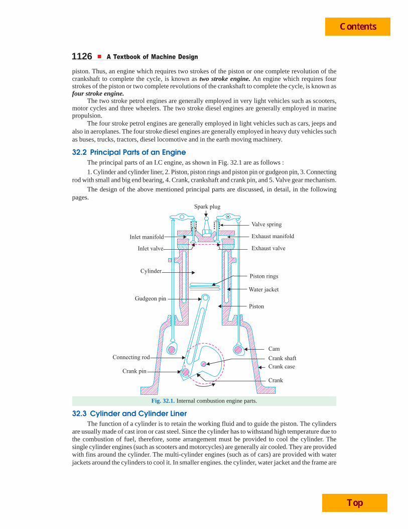
1126 A Textbook of Machine Design
piston. Thus, an engine which requires two strokes of the piston or one complete revolution of thecrankshaft to complete the cycle, is known as two stroke engine. An engine which requires fourstrokes of the piston or two complete revolutions of the crankshaft to complete the cycle, is known asfour stroke engine.
The two stroke petrol engines are generally employed in very light vehicles such as scooters,motor cycles and three wheelers. The two stroke diesel engines are generally employed in marinepropulsion.
The four stroke petrol engines are generally employed in light vehicles such as cars, jeeps andalso in aeroplanes. The four stroke diesel engines are generally employed in heavy duty vehicles suchas buses, trucks, tractors, diesel locomotive and in the earth moving machinery.
32.2 Principal Parts of an EngineThe principal parts of an I.C engine, as shown in Fig. 32.1 are as follows :
1. Cylinder and cylinder liner, 2. Piston, piston rings and piston pin or gudgeon pin, 3. Connectingrod with small and big end bearing, 4. Crank, crankshaft and crank pin, and 5. Valve gear mechanism.
The design of the above mentioned principal parts are discussed, in detail, in the followingpages.
Fig. 32.1. Internal combustion engine parts.
32.3 Cylinder and Cylinder LinerThe function of a cylinder is to retain the working fluid and to guide the piston. The cylinders
are usually made of cast iron or cast steel. Since the cylinder has to withstand high temperature due tothe combustion of fuel, therefore, some arrangement must be provided to cool the cylinder. Thesingle cylinder engines (such as scooters and motorcycles) are generally air cooled. They are providedwith fins around the cylinder. The multi-cylinder engines (such as of cars) are provided with waterjackets around the cylinders to cool it. In smaller engines. the cylinder, water jacket and the frame are
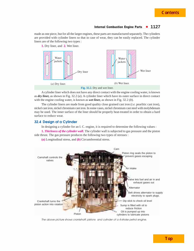
Internal Combustion Engine Parts 1127made as one piece, but for all the larger engines, these parts are manufactured separately. The cylindersare provided with cylinder liners so that in case of wear, they can be easily replaced. The cylinderliners are of the following two types :
1. Dry liner, and 2. Wet liner.
Fig. 32.2. Dry and wet liner.
A cylinder liner which does not have any direct contact with the engine cooling water, is knownas dry liner, as shown in Fig. 32.2 (a). A cylinder liner which have its outer surface in direct contactwith the engine cooling water, is known as wet liner, as shown in Fig. 32.2 (b).
The cylinder liners are made from good quality close grained cast iron (i.e. pearlitic cast iron),nickel cast iron, nickel chromium cast iron. In some cases, nickel chromium cast steel with molybdenummay be used. The inner surface of the liner should be properly heat-treated in order to obtain a hardsurface to reduce wear.
32.4 Design of a CylinderIn designing a cylinder for an I. C. engine, it is required to determine the following values :
1. Thickness of the cylinder wall. The cylinder wall is subjected to gas pressure and the pistonside thrust. The gas pressure produces the following two types of stresses :
(a) Longitudinal stress, and (b) Circumferential stress.
The above picture shows crankshaft, pistons and cylinder of a 4-stroke petrol engine.
Oil is pumped up intocylinders to lubricate pistons
Sump is filled with oil toreduce friction
Dip stick to check oil level
Belt drives alternator to supplyelectricity to spark plugs.
Alternator
Valve lets fuel and air in andexhaust gases out
Air intake
Piston ring seals the piston toprevent gases escaping
Cam
Camshaft controls thevalves
Crankshaft turns thepiston action into rotation
Piston
1128 A Textbook of Machine Design
Since these two stressess act at right angles to each other, therefore, the net stress in eachdirection is reduced.
The piston side thrust tends to bend the cylinder wall, but the stress in the wall due to side thrustis very small and hence it may be neglected.
Let D0 = Outside diameter of the cylinder in mm,D = Inside diameter of the cylinder in mm,p = Maximum pressure inside the engine cylinder in N/mm2,t = Thickness of the cylinder wall in mm, and
1/m = Poisson’s ratio. It is usually taken as 0.25.
The apparent longitudinal stress is given by
22
2 22 2 0
0
Force .4=Area ( )[( ) ]
4
l
D p D p
D DD D
π × ×σ = =
π −−
and the apparent circumferential stresss is given by
ForceArea 2 2c
D l p D pt l t
× × ×σ = = =×
... (where l is the length of the cylinder and area is the projected area)
∴ Net longitudinal stress = cl m
σσ −
and net circumferential stress = lc m
σσ −
The thickness of a cylinder wall (t) is usually obtained by using a thin cylindrical formula,i.e.,
t = 2 c
p DC
× +σ
where p = Maximum pressure inside the cylinder in N/mm2,
D = Inside diameter of the cylinder or cylinder bore in mm,
cσ = Permissible circumferential or hoop stress for the cylinder material
in MPa or N/mm2. Its value may be taken from 35 MPa to100 MPa depending upon the size and material of the cylinder.
C = Allowance for reboring.
The allowance for reboring (C ) depending upon the cylinder bore (D) for I. C. engines is givenin the following table :
Table 32.1. Allowance for reboring for I. C. engine cylinders.
D (mm) 75 100 150 200 250 300 350 400 450 500
C (mm) 1.5 2.4 4.0 6.3 8.0 9.5 11.0 12.5 12.5 12.5
The thickness of the cylinder wall usually varies from 4.5 mm to 25 mm or more dependingupon the size of the cylinder. The thickness of the cylinder wall (t) may also be obtained from thefollowing empirical relation, i.e.
t = 0.045 D + 1.6 mm
The other empirical relations are as follows :
Thickness of the dry liner
= 0.03 D to 0.035 D
Internal Combustion Engine Parts 1129Thickness of the water jacket wall
= 0.032 D + 1.6 mm or t / 3 m for bigger cylinders and 3t /4 forsmaller cylinders
Water space between the outer cylinder wall and inner jacket wall
= 10 mm for a 75 mm cylinder to 75 mm for a 750 mm cylinder
or 0.08 D + 6.5 mm
2. Bore and length of the cylinder. The bore (i.e. inner diameter) and length of the cylinder maybe determined as discussed below :
Let pm = Indicated mean effective pressure in N/mm2,
D = Cylinder bore in mm,
A = Cross-sectional area of the cylinder in mm2,
= π D2/4
l = Length of stroke in metres,
N = Speed of the engine in r.p.m., and
n = Number of working strokes per min
= N, for two stroke engine
= N/2, for four stroke engine.
We know that the power produced inside the engine cylinder, i.e. indicated power,
. . watts60
mp l A nI P
× × ×=
From this expression, the bore (D) and length of stroke (l) is determined. The length of stroke isgenerally taken as 1.25 D to 2D.
Since there is a clearance on both sides of the cylinder, therefore length of the cylinder is takenas 15 percent greater than the length of stroke. In other words,
Length of the cylinder, L = 1.15 × Length of stroke = 1.15 lNotes : (a) If the power developed at the crankshaft, i.e. brake power (B. P.) and the mechanical efficiency (ηm)of the engine is known, then
I.P. =. .
m
B Pη
(b) The maximum gas pressure ( p ) may be taken as 9 to 10 times the mean effective pressure ( pm).
3. Cylinder flange and studs. The cylinders are cast integral with the upper half of the crank-case or they are attached to the crankcase by means of a flange with studs or bolts and nuts. Thecylinder flange is integral with the cylinder and should be made thicker than the cylinder wall. Theflange thickness should be taken as 1.2 t to 1.4 t, where t is the thickness of cylinder wall.
The diameter of the studs or bolts may be obtained by equating the gas load due to the maximumpressure in the cylinder to the resisting force offered by all the studs or bolts. Mathematically,
2 .4
D pπ × = 2( )
4s c tn dπ× σ
where D = Cylinder bore in mm,
p = Maximum pressure in N/mm2,
ns = Number of studs. It may be taken as 0.01 D + 4 to 0.02 D + 4
dc = Core or minor diameter, i.e. diameter at the root of the thread inmm,
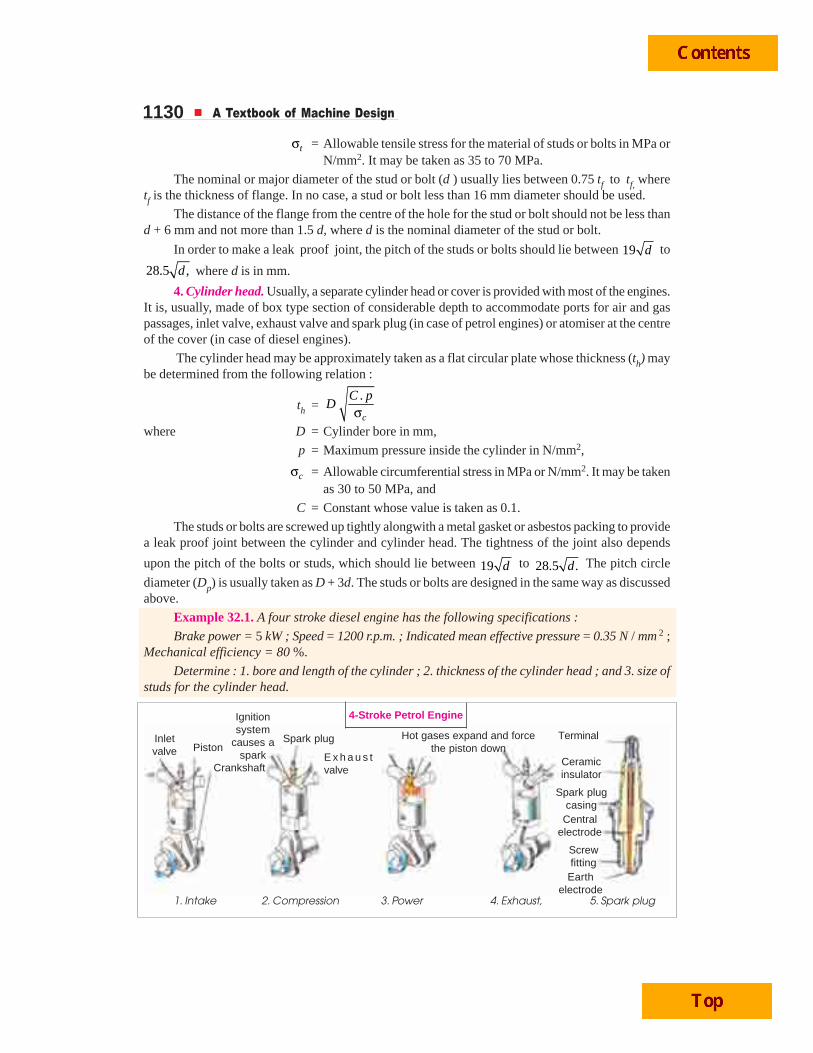
1130 A Textbook of Machine Design
tσ = Allowable tensile stress for the material of studs or bolts in MPa orN/mm2. It may be taken as 35 to 70 MPa.
The nominal or major diameter of the stud or bolt (d ) usually lies between 0.75 tf to tf, wheretf is the thickness of flange. In no case, a stud or bolt less than 16 mm diameter should be used.
The distance of the flange from the centre of the hole for the stud or bolt should not be less thand + 6 mm and not more than 1.5 d, where d is the nominal diameter of the stud or bolt.
In order to make a leak proof joint, the pitch of the studs or bolts should lie between 19 d to
28.5 ,d where d is in mm.
4. Cylinder head. Usually, a separate cylinder head or cover is provided with most of the engines.It is, usually, made of box type section of considerable depth to accommodate ports for air and gaspassages, inlet valve, exhaust valve and spark plug (in case of petrol engines) or atomiser at the centreof the cover (in case of diesel engines).
The cylinder head may be approximately taken as a flat circular plate whose thickness (th) maybe determined from the following relation :
th =.
c
C pD
σwhere D = Cylinder bore in mm,
p = Maximum pressure inside the cylinder in N/mm2,
cσ = Allowable circumferential stress in MPa or N/mm2. It may be takenas 30 to 50 MPa, and
C = Constant whose value is taken as 0.1.
The studs or bolts are screwed up tightly alongwith a metal gasket or asbestos packing to providea leak proof joint between the cylinder and cylinder head. The tightness of the joint also depends
upon the pitch of the bolts or studs, which should lie between 19 d to 28.5 .d The pitch circle
diameter (Dp) is usually taken as D + 3d. The studs or bolts are designed in the same way as discussedabove.
Example 32.1. A four stroke diesel engine has the following specifications :
Brake power = 5 kW ; Speed = 1200 r.p.m. ; Indicated mean effective pressure = 0.35 N / mm 2 ;Mechanical efficiency = 80 %.
Determine : 1. bore and length of the cylinder ; 2. thickness of the cylinder head ; and 3. size ofstuds for the cylinder head.
1. Intake 2. Compression 3. Power 4. Exhaust, 5. Spark plug
Inletvalve Piston
Crankshaft
Ignitionsystem
causes aspark
Spark plug
E x h a u s tvalve
Hot gases expand and forcethe piston down
Terminal
Ceramicinsulator
Spark plugcasing
Centralelectrode
Screwfitting
Earthelectrode
4-Stroke Petrol Engine
Internal Combustion Engine Parts 1131Solution. Given: B.P. = 5kW = 5000 W ; N = 1200 r.p.m. or n = N / 2 = 600 ;
pm = 0.35 N/mm2; ηm = 80% = 0.8
1. Bore and length of cylinderLet D = Bore of the cylinder in mm,
A = Cross-sectional area of the cylinder = 2 2mm4π × D
l = Length of the stroke in m.
= 1.5 D mm = 1.5 D / 1000 m ....(Assume)
We know that the indicated power,
I.P = B.P. / ηm = 5000 / 0.8 = 6250 W
We also know that the indicated power (I.P.),
6250 =2. . . 0.35 1.5 600
60 60 1000 4mp l A n D D× × π ×=
× × = 4.12 × 10⁻³ D3
...(Q For four stroke engine, n = N/2)
∴ D3 = 6250 / 4.12 × 10–3 = 1517 × 103 or D = 115 mm Ans.and l = 1.5 D = 1.5 × 115 = 172.5 mm
Taking a clearance on both sides of the cylinder equal to 15% of the stroke, therefore length ofthe cylinder,
L = 1.15 l = 1.15 × 172.5 = 198 say 200 mm Ans.2. Thickness of the cylinder head
Since the maximum pressure ( p) in the engine cylinder is taken as 9 to 10 times the meaneffective pressure ( pm), therefore let us take
p = 9 pm = 9 × 0.35 = 3.15 N/mm2
We know that thickness of the cyclinder head,
th =. 0.1 3.15
11542t
C pD
×=σ = 9.96 say 10 mm Ans.
...(Taking C = 0.1 and tσ = 42 MPa = 42 N/mm2)
3. Size of studs for the cylinder headLet d = Nominal diameter of the stud in mm,
dc = Core diameter of the stud in mm. It is usually taken as 0.84 d.
σt = Tensile stress for the material of the stud which is usually nickelsteel.
ns = Number of studs.
We know that the force acting on the cylinder head (or on the studs)
= 2 2(115) 3.15 32 702 N4 4
D pπ π× × = = ...(i)
The number of studs (ns ) are usually taken between 0.01 D + 4 (i.e. 0.01 × 115 + 4 = 5.15) and0.02 D + 4 (i.e. 0.02 × 115 + 4 = 6.3). Let us take ns = 6.
We know that resisting force offered by all the studs
= 2 2 2( ) 6 (0.84 ) 65 216 N4 4s c tn d d dπ π× σ = × = ...(ii)
...(Taking σt = 65 MPa = 65 N/mm2)From equations (i) and (ii),
d 2 = 32 702 / 216 = 151 or d = 12.3 say 14 mm
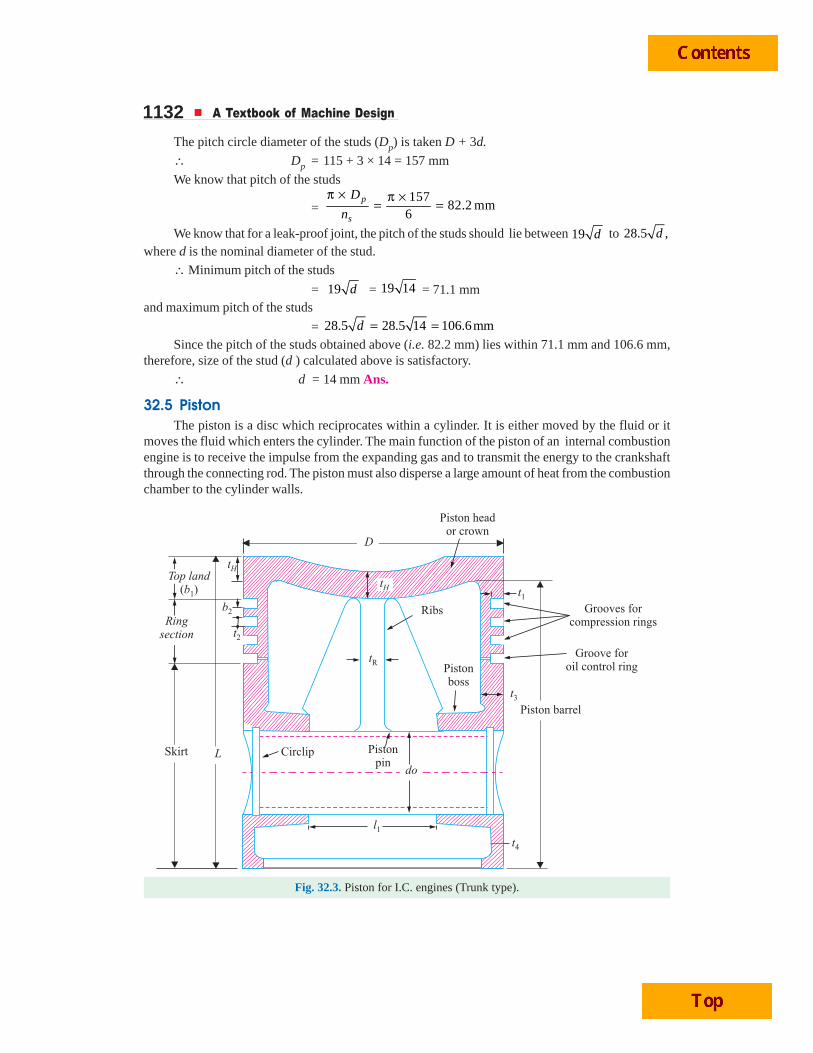
1132 A Textbook of Machine Design
The pitch circle diameter of the studs (Dp) is taken D + 3d.
∴ Dp = 115 + 3 × 14 = 157 mm
We know that pitch of the studs
=157
82.2 mm6
p
s
D
n
π × π ×= =
We know that for a leak-proof joint, the pitch of the studs should lie between 19 d to 28.5 ,dwhere d is the nominal diameter of the stud.
∴ Minimum pitch of the studs
= 19 d = 19 14 = 71.1 mmand maximum pitch of the studs
= 28.5 28.5 14 106.6mmd = =Since the pitch of the studs obtained above (i.e. 82.2 mm) lies within 71.1 mm and 106.6 mm,
therefore, size of the stud (d ) calculated above is satisfactory.
∴ d = 14 mm Ans.
32.5 PistonThe piston is a disc which reciprocates within a cylinder. It is either moved by the fluid or it
moves the fluid which enters the cylinder. The main function of the piston of an internal combustionengine is to receive the impulse from the expanding gas and to transmit the energy to the crankshaftthrough the connecting rod. The piston must also disperse a large amount of heat from the combustionchamber to the cylinder walls.
Fig. 32.3. Piston for I.C. engines (Trunk type).
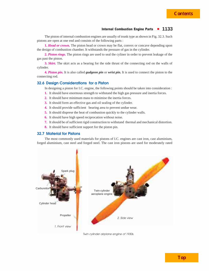
Internal Combustion Engine Parts 1133The piston of internal combustion engines are usually of trunk type as shown in Fig. 32.3. Such
pistons are open at one end and consists of the following parts :
1. Head or crown. The piston head or crown may be flat, convex or concave depending uponthe design of combustion chamber. It withstands the pressure of gas in the cylinder.
2. Piston rings. The piston rings are used to seal the cyliner in order to prevent leakage of thegas past the piston.
3. Skirt. The skirt acts as a bearing for the side thrust of the connecting rod on the walls ofcylinder.
4. Piston pin. It is also called gudgeon pin or wrist pin. It is used to connect the piston to theconnecting rod.
32.6 Design Considerations for a PistonIn designing a piston for I.C. engine, the following points should be taken into consideration :
1. It should have enormous strength to withstand the high gas pressure and inertia forces.
2. It should have minimum mass to minimise the inertia forces.
3. It should form an effective gas and oil sealing of the cylinder.
4. It should provide sufficient bearing area to prevent undue wear.
5. It should disprese the heat of combustion quickly to the cylinder walls.
6. It should have high speed reciprocation without noise.
7. It should be of sufficient rigid construction to withstand thermal and mechanical distortion.
8. It should have sufficient support for the piston pin.
32.7 Material for PistonsThe most commonly used materials for pistons of I.C. engines are cast iron, cast aluminium,
forged aluminium, cast steel and forged steel. The cast iron pistons are used for moderately rated
Twin cylinder airplane engine of 1930s.
Spark plug
Carburettor
Cylinder head
Propeller
Twin-cylinderaeroplane engine
1. Front view
2. Side view
1134 A Textbook of Machine Design
engines with piston speeds below 6 m / s and aluminium alloy pistons are used for highly rated en-gines running at higher piston sppeds. It may be noted that
1. Since the *coefficient of thermal expansion for aluminium is about 2.5 times that of cast iron,therefore, a greater clearance must be provided between the piston and the cylinder wall (than withcast iron piston) in order to prevent siezing of the piston when engine runs continuously under heavyloads. But if excessive clearance is allowed, then the piston will develop ‘piston slap’ while it is coldand this tendency increases with wear. The less clearance between the piston and the cylinder wallwill lead to siezing of piston.
2. Since the aluminium alloys used for pistons have high **heat conductivity (nearly fourtimes that of cast iron), therefore, these pistons ensure high rate of heat transfer and thus keepsdown the maximum temperature difference between the centre and edges of the piston head orcrown.Notes: (a) For a cast iron piston, the temperature at the centre of the piston head (TC) is about 425°C to 450°Cunder full load conditions and the temperature at the edges of the piston head (TE) is about 200°C to 225°C.
(b) For aluminium alloy pistons, TC is about 260°C to 290°C and TE is about 185°C to 215°C.
3. Since the aluminium alloys are about ***three times lighter than cast iron, therfore, itsmechanical strength is good at low temperatures, but they lose their strength (about 50%) at temperaturesabove 325°C. Sometimes, the pistons of aluminium alloys are coated with aluminium oxide by anelectrical method.
32.8 Piston Head or CrownThe piston head or crown is designed keeping in view the following two main considerations, i.e.
1. It should have adequate strength to withstand the straining action due to pressure of explosioninside the engine cylinder, and
2. It should dissipate the heat of combustion to the cylinder walls as quickly as possible.
On the basis of first consideration of straining action, the thickness of the piston head is determinedby treating it as a flat circular plate of uniform thickness, fixed at the outer edges and subjected to auniformly distributed load due to the gas pressure over the entire cross-section.
The thickness of the piston head (tH ), according to Grashoff’s formula is given by
tH =23 .
16 t
p Dσ (in mm) ...(i)
where p = Maximum gas pressure or explosion pressure in N/mm2,
D = Cylinder bore or outside diameter of the piston in mm, and
σt = Permissible bending (tensile) stress for the material of the piston inMPa or N/mm2. It may be taken as 35 to 40 MPa for grey cast iron,50 to 90 MPa for nickel cast iron and aluminium alloy and 60 to100 MPa for forged steel.
On the basis of second consideration of heat transfer, the thickness of the piston head should besuch that the heat absorbed by the piston due combustion of fuel is quickly transferred to the cylinderwalls. Treating the piston head as a flat ciucular plate, its thickness is given by
tH =C E12.56 ( )
Hk T T− (in mm) ...(ii)
* The coefficient of thermal expansion for aluminium is 0.24 × 10⁻⁶ m / °C and for cast iron it is 0.1 × 10⁻⁶ m / °C.** The heat conductivity for aluminium is 174.75 W/m/°C and for cast iron it is 46.6 W/m /°C.
*** The density of aluminium is 2700 kg / m3 and for cast iron it is 7200 kg / m3.
Internal Combustion Engine Parts 1135where H = Heat flowing through the piston head in kJ/s or watts,
k = Heat conductivity factor in W/m/°C. Its value is 46.6 W/m/°C forgrey cast iron, 51.25 W/m/°C for steel and 174.75 W/m/°C foraluminium alloys.
TC = Temperture at the centre of the piston head in °C, and
TE = Temperature at the edges of the piston head in °C.
The temperature difference (TC – TE) may be taken as 220°C for cast iron and 75°C for aluminium.
The heat flowing through the positon head (H) may be deternined by the following expression, i.e.,
H = C × HCV × m × B.P. (in kW)
where C = Constant representing that portion of the heat supplied to the enginewhich is absorbed by the piston. Its value is usually takenas 0.05.
HCV = Higher calorific value of the fuel in kJ/kg. It may be taken as45 × 103 kJ/kg for diesel and 47 × 103 kJ/ kg for petrol,
m = Mass of the fuel used in kg per brake power per second, and
B.P. = Brake power of the engine per cylinderNotes : 1. The thickness of the piston head (tH) is calculated by using equations (i) and (ii) and larger of the twovalues obtained should be adopted.
2. When tH is 6 mm or less, then no ribs are required to strengthen the piston head against gas loads. Butwhen tH is greater then 6 mm, then a suitable number of ribs at the centre line of the boss extending around theskirt should be provided to distribute the side thrust from the connecting rod and thus to prevent distortion of theskirt. The thickness of the ribs may be takes as tH / 3 to tH / 2.
3. For engines having length of stroke to cylinder bore (L / D) ratio upto 1.5, a cup is provided in the topof the piston head with a radius equal to 0.7 D. This is done to provide a space for combustion chamber.
32.9 Piston RingsThe piston rings are used to impart the necessary radial pressure to maintain the seal between
the piston and the cylinder bore. These are usually made of grey cast iron or alloy cast iron because oftheir good wearing properties and also they retain spring characteristics even at high temperatures.The piston rings are of the following two types :
1. Compression rings or pressure rings, and
2. Oil control rings or oil scraper.
The compression rings or pressure rings are inserted in the grooves at the top portion of thepiston and may be three to seven in number. These rings also transfer heat from the piston to thecylinder liner and absorb some part of the piston fluctuation due to the side thrust.
The oil control rings or oil scrapers are provided below the compression rings. These ringsprovide proper lubrication to the liner by allowing sufficient oil to move up during upward stroke andat the same time scraps the lubricating oil from the surface of the liner in order to minimise the flowof the oil to the combustion chamber.
The compression rings are usually made of rectangular cross-section and the diameter of thering is slightly larger than the cylinder bore. A part of the ring is cut- off in order to permit it to go intothe cylinder against the liner wall. The diagonal cut or step cut ends, as shown in Fig. 32.4 (a) and (b)respectively, may be used. The gap between the ends should be sufficiently large when the ring is putcold so that even at the highest temperature, the ends do not touch each other when the ring expands,otherwise there might be buckling of the ring.
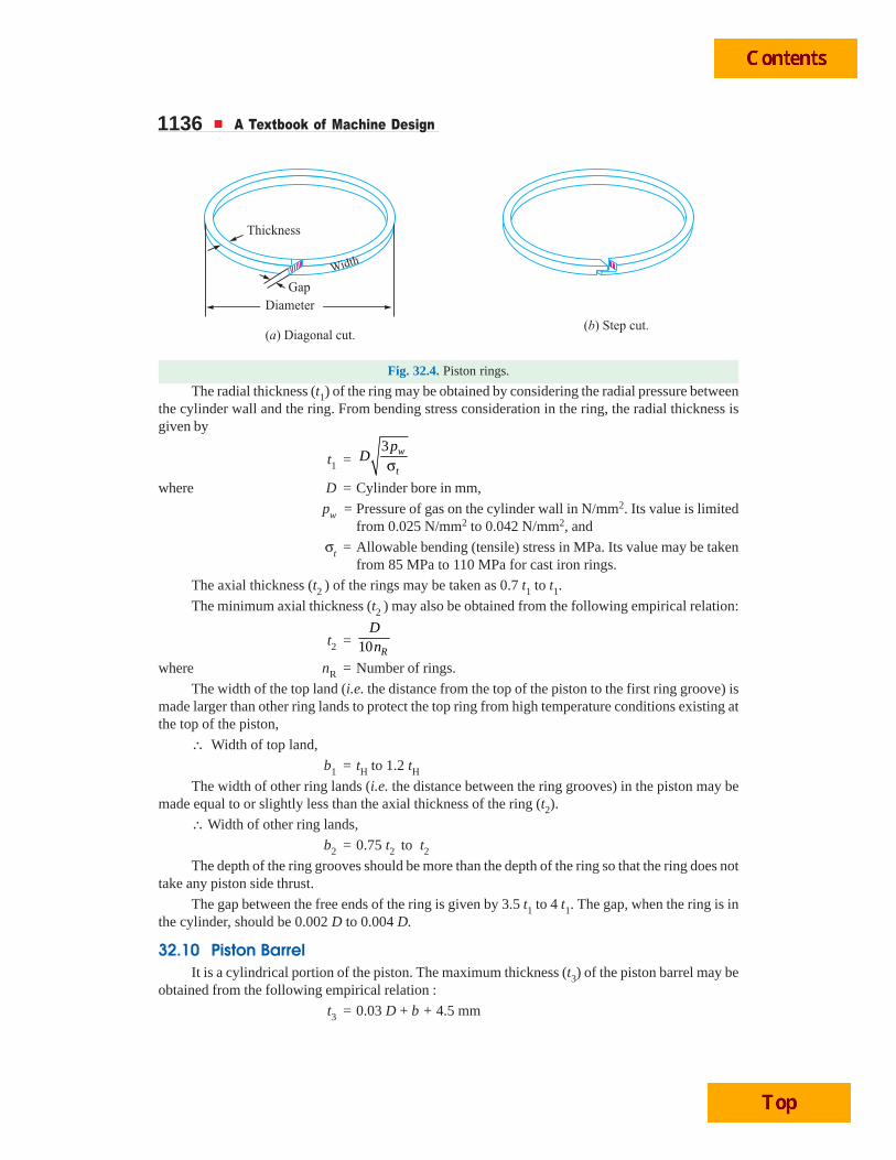
1136 A Textbook of Machine Design
Fig. 32.4. Piston rings.
The radial thickness (t1) of the ring may be obtained by considering the radial pressure betweenthe cylinder wall and the ring. From bending stress consideration in the ring, the radial thickness isgiven by
t1 =3 w
t
pD
σwhere D = Cylinder bore in mm,
pw = Pressure of gas on the cylinder wall in N/mm2. Its value is limitedfrom 0.025 N/mm2 to 0.042 N/mm2, and
σt = Allowable bending (tensile) stress in MPa. Its value may be takenfrom 85 MPa to 110 MPa for cast iron rings.
The axial thickness (t2 ) of the rings may be taken as 0.7 t1 to t1.
The minimum axial thickness (t2 ) may also be obtained from the following empirical relation:
t2 = 10 R
Dn
where nR = Number of rings.
The width of the top land (i.e. the distance from the top of the piston to the first ring groove) ismade larger than other ring lands to protect the top ring from high temperature conditions existing atthe top of the piston,
∴ Width of top land,
b1 = tH to 1.2 tHThe width of other ring lands (i.e. the distance between the ring grooves) in the piston may be
made equal to or slightly less than the axial thickness of the ring (t2).
∴ Width of other ring lands,
b2 = 0.75 t2 to t2The depth of the ring grooves should be more than the depth of the ring so that the ring does not
take any piston side thrust.
The gap between the free ends of the ring is given by 3.5 t1 to 4 t1. The gap, when the ring is inthe cylinder, should be 0.002 D to 0.004 D.
32.10 Piston BarrelIt is a cylindrical portion of the piston. The maximum thickness (t3) of the piston barrel may be
obtained from the following empirical relation :
t3 = 0.03 D + b + 4.5 mm
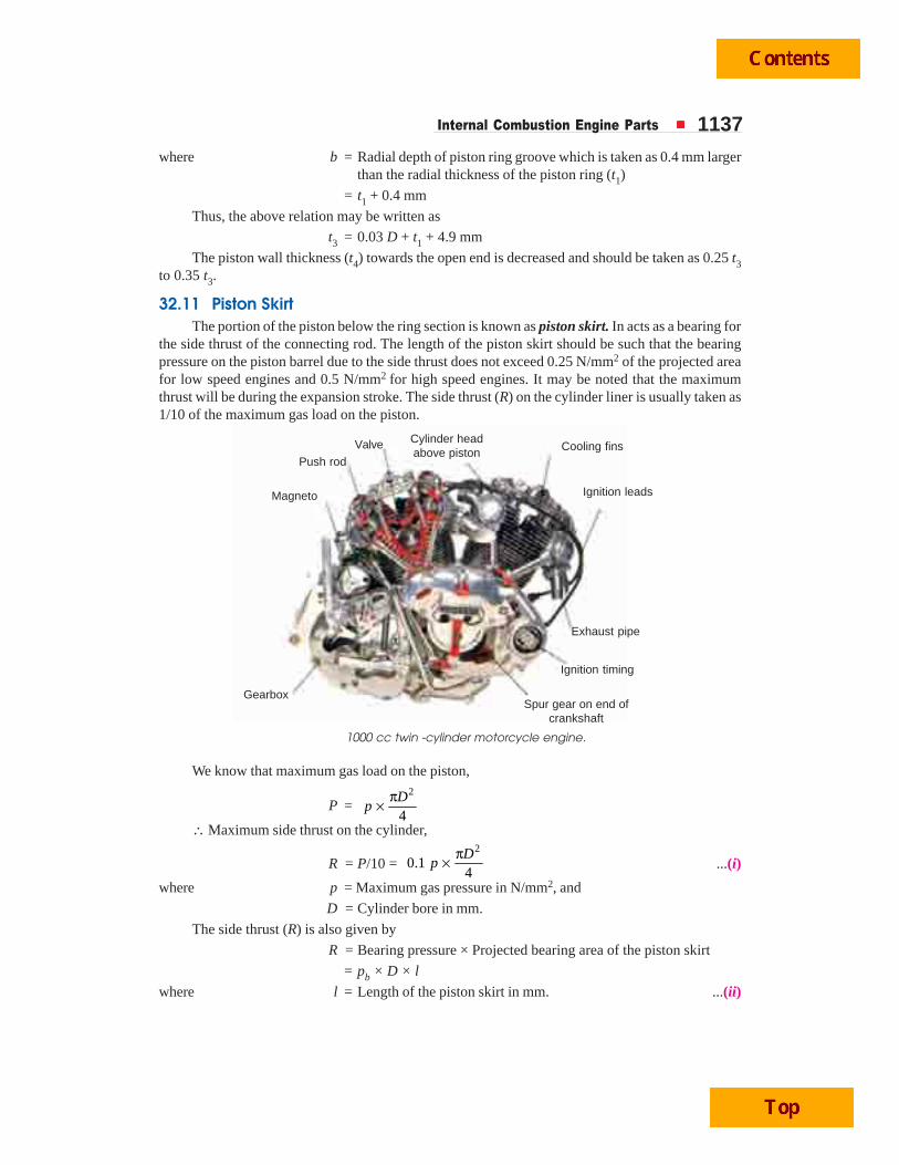
Internal Combustion Engine Parts 1137where b = Radial depth of piston ring groove which is taken as 0.4 mm larger
than the radial thickness of the piston ring (t1)
= t1 + 0.4 mm
Thus, the above relation may be written as
t3 = 0.03 D + t1 + 4.9 mm
The piston wall thickness (t4) towards the open end is decreased and should be taken as 0.25 t3to 0.35 t3.
32.11 Piston SkirtThe portion of the piston below the ring section is known as piston skirt. In acts as a bearing for
the side thrust of the connecting rod. The length of the piston skirt should be such that the bearingpressure on the piston barrel due to the side thrust does not exceed 0.25 N/mm2 of the projected areafor low speed engines and 0.5 N/mm2 for high speed engines. It may be noted that the maximumthrust will be during the expansion stroke. The side thrust (R) on the cylinder liner is usually taken as1/10 of the maximum gas load on the piston.
We know that maximum gas load on the piston,
P =2
4D
pπ×
∴ Maximum side thrust on the cylinder,
R = P/10 = 2
0.14D
pπ× ...(i)
where p = Maximum gas pressure in N/mm2, and
D = Cylinder bore in mm.
The side thrust (R) is also given by
R = Bearing pressure × Projected bearing area of the piston skirt
= pb × D × l
where l = Length of the piston skirt in mm. ...(ii)
1000 cc twin -cylinder motorcycle engine.
Valve
Push rod
Magneto
Cylinder headabove piston Cooling fins
Ignition leads
Exhaust pipe
Ignition timing
Spur gear on end ofcrankshaft
Gearbox
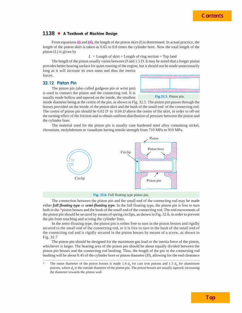
1138 A Textbook of Machine Design
From equations (i) and (ii), the length of the piston skirt (l) is determined. In actual practice, thelength of the piston skirt is taken as 0.65 to 0.8 times the cylinder bore. Now the total length of thepiston (L) is given by
L = Length of skirt + Length of ring section + Top landThe length of the piston usually varies between D and 1.5 D. It may be noted that a longer piston
provides better bearing surface for quiet running of the engine, but it should not be made unnecessarilylong as it will increase its own mass and thus the inertiaforces.
32.12 Piston PinThe piston pin (also called gudgeon pin or wrist pin)
is used to connect the piston and the connecting rod. It isusually made hollow and tapered on the inside, the smallestinside diameter being at the centre of the pin, as shown in Fig. 32.5. The piston pin passes through thebosses provided on the inside of the piston skirt and the bush of the small end of the connecting rod.The centre of piston pin should be 0.02 D to 0.04 D above the centre of the skirt, in order to off-setthe turning effect of the friction and to obtain uniform distribution of pressure between the piston andthe cylinder liner.
The material used for the piston pin is usually case hardened steel alloy containing nickel,chromium, molybdenum or vanadium having tensile strength from 710 MPa to 910 MPa.
Fig. 32.6. Full floating type piston pin.
The connection between the piston pin and the small end of the connecting rod may be madeeither full floating type or semi-floating type. In the full floating type, the piston pin is free to turnboth in the *piston bosses and the bush of the small end of the connecting rod. The end movements ofthe piston pin should be secured by means of spring circlips, as shown in Fig. 32.6, in order to preventthe pin from touching and scoring the cylinder liner.
In the semi-floating type, the piston pin is either free to turn in the piston bosses and rigidlysecured to the small end of the connecting rod, or it is free to turn in the bush of the small end ofthe connecting rod and is rigidly secured in the piston bosses by means of a screw, as shown inFig. 32.7
The piston pin should be designed for the maximum gas load or the inertia force of the piston,whichever is larger. The bearing area of the piston pin should be about equally divided between thepiston pin bosses and the connecting rod bushing. Thus, the length of the pin in the connecting rodbushing will be about 0.45 of the cylinder bore or piston diameter (D), allowing for the end clearance
Fig.32.5. Piston pin.
* The mean diameter of the piston bosses is made 1.4 d0 for cast iron pistons and 1.5 d0 for aluminiumpistons, where d0 is the outside diameter of the piston pin. The piston bosses are usually tapered, increasingthe diameter towards the piston wall.
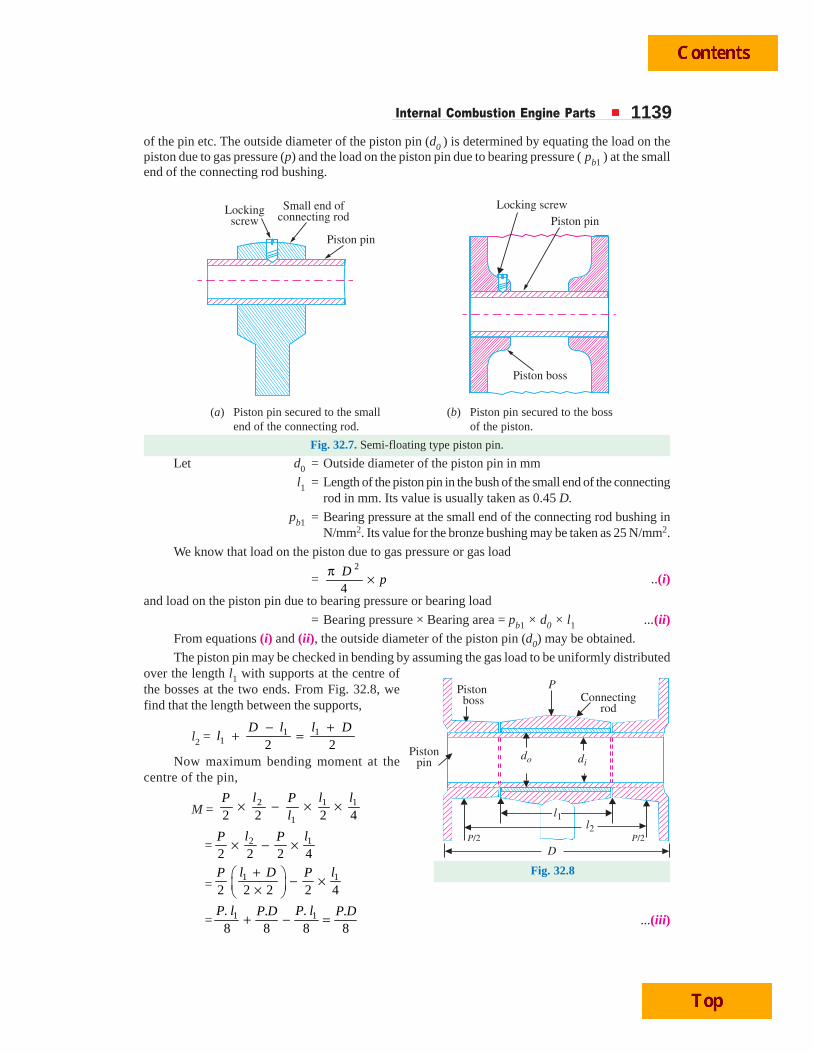
Internal Combustion Engine Parts 1139of the pin etc. The outside diameter of the piston pin (d0 ) is determined by equating the load on thepiston due to gas pressure (p) and the load on the piston pin due to bearing pressure ( pb1 ) at the smallend of the connecting rod bushing.
(a) Piston pin secured to the small (b) Piston pin secured to the bossend of the connecting rod. of the piston.
Fig. 32.7. Semi-floating type piston pin.
Let d0 = Outside diameter of the piston pin in mm
l1 = Length of the piston pin in the bush of the small end of the connectingrod in mm. Its value is usually taken as 0.45 D.
pb1 = Bearing pressure at the small end of the connecting rod bushing inN/mm2. Its value for the bronze bushing may be taken as 25 N/mm2.
We know that load on the piston due to gas pressure or gas load
=2
4D
pπ × ..(i)
and load on the piston pin due to bearing pressure or bearing load
= Bearing pressure × Bearing area = pb1 × d0 × l1 ...(ii)From equations (i) and (ii), the outside diameter of the piston pin (d0) may be obtained.
The piston pin may be checked in bending by assuming the gas load to be uniformly distributedover the length l1 with supports at the centre ofthe bosses at the two ends. From Fig. 32.8, wefind that the length between the supports,
l2 = 1 11 2 2
− ++ =
D l l Dl
Now maximum bending moment at thecentre of the pin,
M = 2 1 1
12 2 2 4× − × ×
l l lP Pl
= 2 1
2 2 2 4× − ×
l lP P
=1 1
2 2 2 2 4+⎛ ⎞ − ×⎜ ⎟×⎝ ⎠
l D lP P
= 1 1. .. .8 8 8 8
+ − =P l P lP D P D
...(iii)
Fig. 32.8
1140 A Textbook of Machine Design
We have already discussed that the piston pin is made hollow. Let d0 and di be the outside andinside diameters of the piston pin. We know that the section modulus,
Z =4 4
0
0
( ) ( )32
⎡ ⎤−π⎢ ⎥⎢ ⎥⎣ ⎦
id dd
We know that maximum bending moment,
M =4 4
0
0
( ) ( )32
⎡ ⎤−π× σ = σ⎢ ⎥⎢ ⎥⎣ ⎦
ib b
d dZ
d
where bσ = Allowable bending stress for the material of the piston pin. It is
usually taken as 84 MPa for case hardened carbon steel and140 MPa for heat treated alloy steel.
Assuming di = 0.6 d0, the induced bending stress in the piston pin may be checked.
Example 32.2. Design a cast iron piston for a single acting four stroke engine for the followingdata:
Cylinder bore = 100 mm ; Stroke = 125 mm ; Maximum gas pressure = 5 N/mm2 ; Indicatedmean effective pressure = 0.75 N/mm2 ; Mechanical efficiency = 80% ; Fuel consumption = 0.15 kgper brake power per hour ; Higher calorific value of fuel = 42 × 103 kJ/kg ; Speed = 2000 r.p.m.
Any other data required for the design may be assumed.
Solution. Given : D = 100 mm ; L = 125 mm = 0.125 m ; p = 5 N/mm2 ; pm = 0.75 N/mm2;
mη = 80% = 0.8 ; m = 0.15 kg / BP / h = 41.7 × 10⁻⁶ kg / BP / s; HCV = 42 × 103 kJ / kg ;
N = 2000 r.p.m.
The dimensions for various components of the piston are determined as follows :
1. Piston head or crownThe thickness of the piston head or crown is determined on the basis of strength as well as on the
basis of heat dissipation and the larger of the two values is adopted.
Another view of a single cylinder 4-stroke petrol engine.
Camshaft ispushed round by
chain
Cam chain is driven bycrankshaft
Waste gases out
Valve
Spark plug
Piston
CrankshaftFuel flows in whenneedle rises
Carburettor
Fuel in
Air in
Spring
Internal Combustion Engine Parts 1141We know that the thickness of piston head on the basis of strength,
tH = 2 23 . 3 5(100)
16 16 38t
p D ×=σ × = 15.7 say 16 mm
...(Taking tσ for cast iron = 38 MPa = 38 N/mm2)
Since the engine is a four stroke engine, therefore, the number of working strokes per minute,
n = N / 2 = 2000 / 2 = 1000
and cross-sectional area of the cylinder,
A =2 2
2(100)7855 mm
4 4Dπ π= =
We know that indicated power,
IP =. . . 0.75 0.125 7855 1000
12 270 W60 60
mp L A n × × ×= =
= 12.27 kW
∴ Brake power, BP = IP × mη = 12.27 × 0.8 = 9.8 kW ...(Q mη = BP / IP)
We know that the heat flowing through the piston head,
H = C × HCV × m × BP
= 0.05 × 42 × 103 × 41.7 × 10–6 × 9.8 = 0.86 kW = 860 W....(Taking C = 0.05)
∴Thickness of the piston head on the basis of heat dissipation,
tH =C E
8600.0067 m 6.7 mm
12.56 ( ) 12.56 46.6 220H
k T T= = =
− × ×...(Q For cast iron , k = 46.6 W/m/°C, and TC – TE = 220°C)
Taking the larger of the two values, we shall adopt
tH = 16 mm Ans.Since the ratio of L / D is 1.25, therefore a cup in the top of the piston head with a radius equal
to 0.7 D (i.e. 70 mm) is provided.
2. Radial ribsThe radial ribs may be four in number. The thickness of the ribs varies from tH / 3 to tH / 2.
∴ Thickness of the ribs, tR = 16 / 3 to 16 / 2 = 5.33 to 8 mm
Let us adopt tR = 7 mm Ans.3. Piston rings
Let us assume that there are total four rings (i.e. nr = 4) out of which three are compression ringsand one is an oil ring.
We know that the radial thickness of the piston rings,
t1 =3 3 0.035
100 3.490
w
t
pD
×= =σ
mm
...(Taking pw = 0.035 N/mm2, and tσ = 90 MPa)
and axial thickness of the piston rings
t2 = 0.7 t1 to t1 = 0.7 × 3.4 to 3.4 mm = 2.38 to 3.4 mm
Let us adopt t2 = 3 mm
1142 A Textbook of Machine Design
We also know that the minimum axial thickness of the pistion ring,
t2 =100
2.5 mm10 10 4
= =×r
Dn
Thus the axial thickness of the piston ring as already calculated (i.e. t2 = 3 mm)is satisfactory. Ans.The distance from the top of the piston to the first ring groove, i.e. the width of the top land,
b1 = tH to 1.2 tH = 16 to 1.2 × 16 mm = 16 to 19.2 mm
and width of other ring lands,
b2 = 0.75 t2 to t2 = 0.75 × 3 to 3 mm = 2.25 to 3 mm
Let us adopt b1 = 18 mm ; and b2 = 2.5 mm Ans.We know that the gap between the free ends of the ring,
G1 = 3.5 t1 to 4 t1 = 3.5 × 3.4 to 4 × 3.4 mm = 11.9 to 13.6 mm
and the gap when the ring is in the cylinder,
G2 = 0.002 D to 0.004 D = 0.002 × 100 to 0.004 × 100 mm
= 0.2 to 0.4 mm
Let us adopt G1 = 12.8 mm ; and G2 = 0.3 mm Ans.4. Piston barrel
Since the radial depth of the piston ring grooves (b) is about 0.4 mm more than the radialthickness of the piston rings (t1), therefore,
b = t1 + 0.4 = 3.4 + 0.4 = 3.8 mm
We know that the maximum thickness of barrel,
t3 = 0.03 D + b + 4.5 mm = 0.03 × 100 + 3.8 + 4.5 = 11.3 mm
and piston wall thickness towards the open end,
t4 = 0.25 t3 to 0.35 t3 = 0.25 × 11.3 to 0.35 × 11.3 = 2.8 to 3.9 mm
Let us adopt t4 = 3.4 mm
5. Piston skirtLet l = Length of the skirt in mm.
We know that the maximum side thrust on the cylinder due to gas pressure ( p ),
R =2 2(100)
0.1 5 3928 N4 4D
pπ πμ × × = × × =
...(Taking μ = 0.1)We also know that the side thrust due to bearing pressure on the piston barrel ( pb ),
R = pb × D × l = 0.45 × 100 × l = 45 l N...(Taking pb = 0.45 N/mm2)
From above, we find that45 l = 3928 or l = 3928 / 45 = 87.3 say 90 mm Ans.
∴ ∴ ∴ ∴ ∴ Total length of the piston ,L = Length of the skirt + Length of the ring section + Top land
= l + (4 t2 + 3b2) + b1
= 90 + (4 × 3 + 3 × 3) + 18 = 129 say 130 mm Ans.6. Piston pin
Let d0 = Outside diameter of the pin in mm,l1 = Length of pin in the bush of the small end of the connecting rod in
mm, and
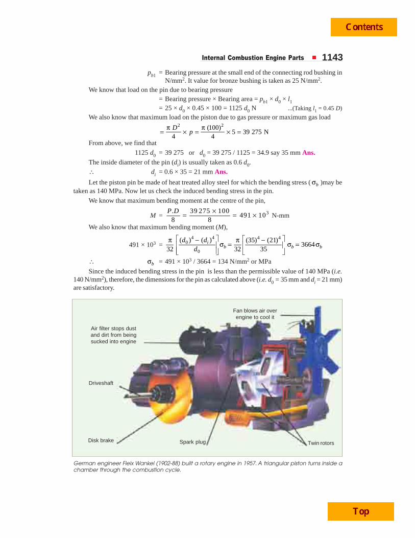
Internal Combustion Engine Parts 1143pb1 = Bearing pressure at the small end of the connecting rod bushing in
N/mm2. It value for bronze bushing is taken as 25 N/mm2.We know that load on the pin due to bearing pressure
= Bearing pressure × Bearing area = pb1 × d0 × l1= 25 × d0 × 0.45 × 100 = 1125 d0 N ...(Taking l1 = 0.45 D)
We also know that maximum load on the piston due to gas pressure or maximum gas load2 2(100)
5 39 275 N4 4D
pπ π= × = × =
From above, we find that
1125 d0 = 39 275 or d0 = 39 275 / 1125 = 34.9 say 35 mm Ans.The inside diameter of the pin (di) is usually taken as 0.6 d0.
∴ di = 0.6 × 35 = 21 mm Ans.
Let the piston pin be made of heat treated alloy steel for which the bending stress ( bσ )may betaken as 140 MPa. Now let us check the induced bending stress in the pin.
We know that maximum bending moment at the centre of the pin,
M = 3. 39 275 100491 10
8 8P D ×= = × N-mm
We also know that maximum bending moment (M),
491 × 103 =4 4 4 4
0
0
( ) ( ) (35) (21)3664
32 32 35i
b b bd d
d
⎡ ⎤ ⎡ ⎤−π π −σ = σ = σ⎢ ⎥ ⎢ ⎥⎢ ⎥ ⎣ ⎦⎣ ⎦
∴ bσ = 491 × 103 / 3664 = 134 N/mm2 or MPa
Since the induced bending stress in the pin is less than the permissible value of 140 MPa (i.e.140 N/mm2), therefore, the dimensions for the pin as calculated above (i.e. d0 = 35 mm and di = 21 mm)are satisfactory.
Air filter stops dustand dirt from beingsucked into engine
German engineer Fleix Wankel (1902-88) built a rotary engine in 1957. A triangular piston turns inside achamber through the combustion cycle.
Driveshaft
Disk brake Spark plug Twin rotors
Fan blows air overengine to cool it
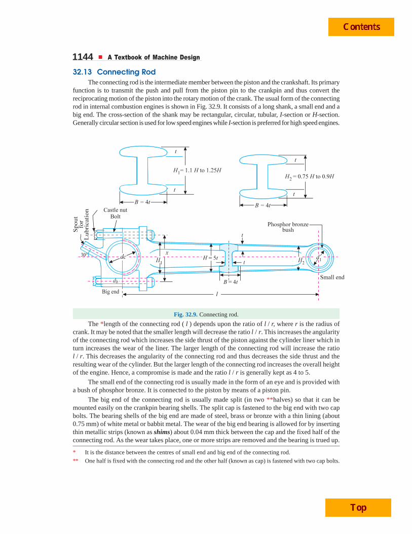
1144 A Textbook of Machine Design
32.13 Connecting RodThe connecting rod is the intermediate member between the piston and the crankshaft. Its primary
function is to transmit the push and pull from the piston pin to the crankpin and thus convert thereciprocating motion of the piston into the rotary motion of the crank. The usual form of the connectingrod in internal combustion engines is shown in Fig. 32.9. It consists of a long shank, a small end and abig end. The cross-section of the shank may be rectangular, circular, tubular, I-section or H-section.Generally circular section is used for low speed engines while I-section is preferred for high speed engines.
Fig. 32.9. Connecting rod.
The *length of the connecting rod ( l ) depends upon the ratio of l / r, where r is the radius ofcrank. It may be noted that the smaller length will decrease the ratio l / r. This increases the angularityof the connecting rod which increases the side thrust of the piston against the cylinder liner which inturn increases the wear of the liner. The larger length of the connecting rod will increase the ratiol / r. This decreases the angularity of the connecting rod and thus decreases the side thrust and theresulting wear of the cylinder. But the larger length of the connecting rod increases the overall heightof the engine. Hence, a compromise is made and the ratio l / r is generally kept as 4 to 5.
The small end of the connecting rod is usually made in the form of an eye and is provided witha bush of phosphor bronze. It is connected to the piston by means of a piston pin.
The big end of the connecting rod is usually made split (in two **halves) so that it can bemounted easily on the crankpin bearing shells. The split cap is fastened to the big end with two capbolts. The bearing shells of the big end are made of steel, brass or bronze with a thin lining (about0.75 mm) of white metal or babbit metal. The wear of the big end bearing is allowed for by insertingthin metallic strips (known as shims) about 0.04 mm thick between the cap and the fixed half of theconnecting rod. As the wear takes place, one or more strips are removed and the bearing is trued up.
* It is the distance between the centres of small end and big end of the connecting rod.
** One half is fixed with the connecting rod and the other half (known as cap) is fastened with two cap bolts.
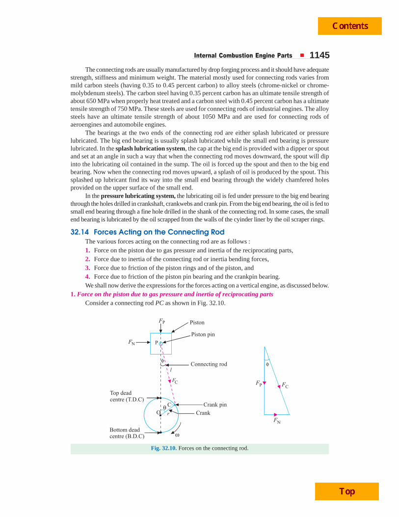
Internal Combustion Engine Parts 1145The connecting rods are usually manufactured by drop forging process and it should have adequate
strength, stiffness and minimum weight. The material mostly used for connecting rods varies frommild carbon steels (having 0.35 to 0.45 percent carbon) to alloy steels (chrome-nickel or chrome-molybdenum steels). The carbon steel having 0.35 percent carbon has an ultimate tensile strength ofabout 650 MPa when properly heat treated and a carbon steel with 0.45 percent carbon has a ultimatetensile strength of 750 MPa. These steels are used for connecting rods of industrial engines. The alloysteels have an ultimate tensile strength of about 1050 MPa and are used for connecting rods ofaeroengines and automobile engines.
The bearings at the two ends of the connecting rod are either splash lubricated or pressurelubricated. The big end bearing is usually splash lubricated while the small end bearing is pressurelubricated. In the splash lubrication system, the cap at the big end is provided with a dipper or spoutand set at an angle in such a way that when the connecting rod moves downward, the spout will dipinto the lubricating oil contained in the sump. The oil is forced up the spout and then to the big endbearing. Now when the connecting rod moves upward, a splash of oil is produced by the spout. Thissplashed up lubricant find its way into the small end bearing through the widely chamfered holesprovided on the upper surface of the small end.
In the pressure lubricating system, the lubricating oil is fed under pressure to the big end bearingthrough the holes drilled in crankshaft, crankwebs and crank pin. From the big end bearing, the oil is fed tosmall end bearing through a fine hole drilled in the shank of the connecting rod. In some cases, the smallend bearing is lubricated by the oil scrapped from the walls of the cyinder liner by the oil scraper rings.
32.14 Forces Acting on the Connecting RodThe various forces acting on the connecting rod are as follows :1. Force on the piston due to gas pressure and inertia of the reciprocating parts,2. Force due to inertia of the connecting rod or inertia bending forces,3. Force due to friction of the piston rings and of the piston, and4. Force due to friction of the piston pin bearing and the crankpin bearing.We shall now derive the expressions for the forces acting on a vertical engine, as discussed below.
1. Force on the piston due to gas pressure and inertia of reciprocating partsConsider a connecting rod PC as shown in Fig. 32.10.
Fig. 32.10. Forces on the connecting rod.
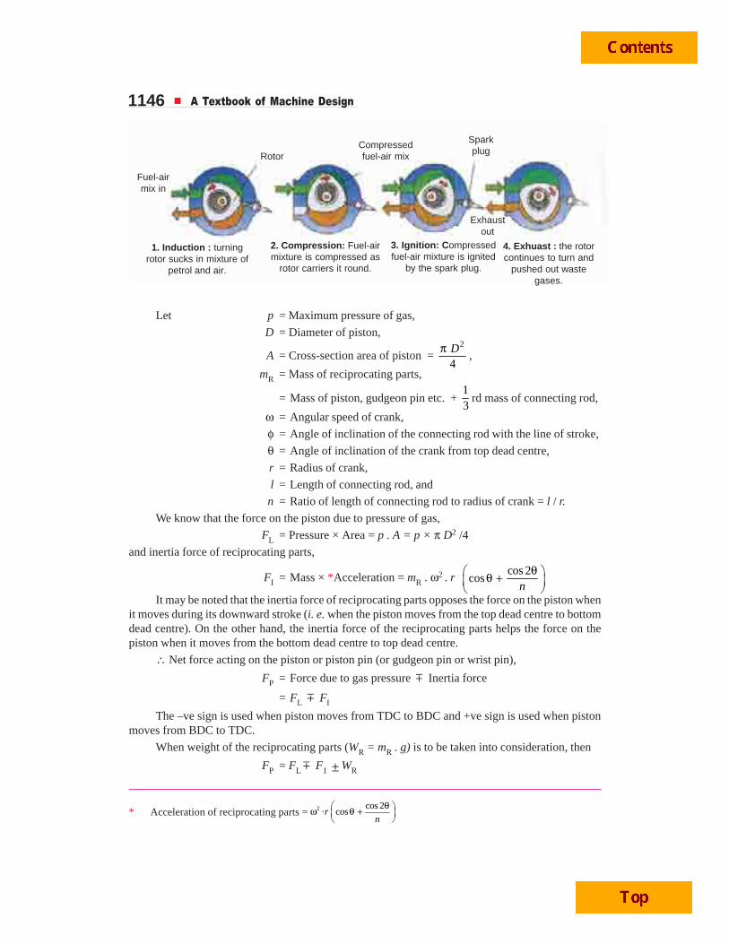
1146 A Textbook of Machine Design
Let p = Maximum pressure of gas,
D = Diameter of piston,
A = Cross-section area of piston = 2
4Dπ
,
mR = Mass of reciprocating parts,
= Mass of piston, gudgeon pin etc. + 13
rd mass of connecting rod,
ω = Angular speed of crank,
φ = Angle of inclination of the connecting rod with the line of stroke,
θ = Angle of inclination of the crank from top dead centre,
r = Radius of crank,
l = Length of connecting rod, and
n = Ratio of length of connecting rod to radius of crank = l / r.
We know that the force on the piston due to pressure of gas,
FL = Pressure × Area = p . A = p × π D2 /4
and inertia force of reciprocating parts,
FI = Mass × *Acceleration = mR . ω2 . r cos 2
cosn
θ⎛ ⎞θ +⎜ ⎟⎝ ⎠
It may be noted that the inertia force of reciprocating parts opposes the force on the piston whenit moves during its downward stroke (i. e. when the piston moves from the top dead centre to bottomdead centre). On the other hand, the inertia force of the reciprocating parts helps the force on thepiston when it moves from the bottom dead centre to top dead centre.
∴ Net force acting on the piston or piston pin (or gudgeon pin or wrist pin),
FP = Force due to gas pressure m Inertia force
= FL m FI
The –ve sign is used when piston moves from TDC to BDC and +ve sign is used when pistonmoves from BDC to TDC.
When weight of the reciprocating parts (WR = mR . g) is to be taken into consideration, then
FP = FL m F1 ± WR
* Acceleration of reciprocating parts = 2 cos 2· cosr
n
θ⎛ ⎞ω θ +⎜ ⎟⎝ ⎠
Fuel-airmix in
RotorCompressedfuel-air mix
Sparkplug
Exhaustout
1. Induction : turningrotor sucks in mixture of
petrol and air.
2. Compression: Fuel-airmixture is compressed as
rotor carriers it round.
3. Ignition: Compressedfuel-air mixture is ignited
by the spark plug.
4. Exhuast : the rotorcontinues to turn and
pushed out wastegases.
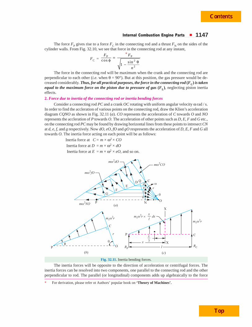
Internal Combustion Engine Parts 1147The force FP gives rise to a force FC in the connecting rod and a thrust FN on the sides of the
cylinder walls. From Fig. 32.10, we see that force in the connecting rod at any instant,
FC =P P
2
2
cos sin1
F F
n
=φ θ−
The force in the connecting rod will be maximum when the crank and the connecting rod areperpendicular to each other (i.e. when θ = 90°). But at this position, the gas pressure would be de-creased considerably. Thus, for all practical purposes, the force in the connecting rod (FC) is takenequal to the maximum force on the piston due to pressure of gas (FL), neglecting piston inertiaeffects.
2. Force due to inertia of the connecting rod or inertia bending forcesConsider a connecting rod PC and a crank OC rotating with uniform angular velocity ω rad / s.
In order to find the accleration of various points on the connecting rod, draw the Klien’s accelerationdiagram CQNO as shown in Fig. 32.11 (a). CO represents the acceleration of C towards O and NOrepresents the accleration of P towards O. The acceleration of other points such as D, E, F and G etc.,on the connecting rod PC may be found by drawing horizontal lines from these points to intresect CNat d, e, f, and g respectively. Now dO, eO, fO and gO respresents the acceleration of D, E, F and G alltowards O. The inertia force acting on each point will be as follows:
Inertia force at C = m × ω2 × CO
Inertia force at D = m × ω2 × dO
Inertia force at E = m × ω2 × eO, and so on.
Fig. 32.11. Inertia bending forces.
The inertia forces will be opposite to the direction of acceleration or centrifugal forces. Theinertia forces can be resolved into two components, one parallel to the connecting rod and the otherperpendicular to rod. The parallel (or longitudinal) components adds up algebraically to the force
* For derivation, please refer ot Authors’ popular book on ‘Theory of Machines’.
*
1148 A Textbook of Machine Design
Co Carbon monoxideCO2 Carbon dioxideNOx Nitrous oxidesHC HydrocarbonsN2 NitrogenH2O WaterMetal casing
Honeycombcoated withmetal catalysts
To exhaust
acting on the connecting rod (FC) and produces thrust on the pins. The perpendicular (or transverse)components produces bending action (also called whipping action) and the stress induced in theconnecting rod is called whipping stress.
It may be noted that the perpendicular components will be maximum, when the crank andconnecting rod are at right angles to each other.
The variation of the inertia force on the connecting rod is linear and is like a simply supportedbeam of variable loading as shown in Fig. 32.11 (b) and (c). Assuming that the connecting rod is ofuniform cross-section and has mass m1 kg per unit length, therefore,
Inertia force per unit length at the crankpin= m1 × ω2 r
and inertia force per unit length at the piston pin= 0
Inertia force due to small element of length dx at a distance x from the piston pin P,
dF1 = m1 × ω2r × xl
× dx
∴ Resultant inertia force,
FI =2 2
2 11
002
llm rx x
m r dxl l
⎡ ⎤× ω× ω × × = ⎢ ⎥
⎣ ⎦∫
= 2 21.2 2
m l mr r× ω = × ω ...(Substituting m1 · l = m)
This resultant inertia force acts at a distance of 2l / 3 from the piston pin P.
Since it has been assumed that 13
rd mass of the connecting rod is concentrated at piston pin P
(i.e. small end of connecting rod) and 23
rd at the crankpin (i.e. big end of connecting rod), therefore,
the reaction at these two ends will be in the same proportion. i.e.
RP = I C I1 2
, an d3 3
F R F=
Emissions of an automobile.
Internal Combustion Engine Parts 1149Now the bending moment acting on the rod at section X – X at a distance x from P,
MX = 2P 1
12 3
x xR x m r x
l× − × ω × × ×
=3
21I 2
.13 2 3
m l xF x r
l× − × ω ×
...(Multiplying and dividing the latter expression by l)
=3 3
I II 2 23 33
F x Fx xF x
l l
⎛ ⎞× − × = −⎜ ⎟⎜ ⎟⎝ ⎠
...(i)
For maximum bending moment, differentiate MX with respect to x and equate to zero, i.e.
MXddx
= 0 or 2
I2
31 0
3F x
l
⎡ ⎤− =⎢ ⎥
⎣ ⎦
∴2
2
31
x
l− = 0 or 2 23 or
3
lx l x= =
Maximum bending moment,
Mmax =
3
I2
33 3
l
F l
l
⎡ ⎤⎛ ⎞⎢ ⎥⎜ ⎟⎢ ⎥⎝ ⎠−⎢ ⎥⎣ ⎦
...[From equation (i)]
=I I I22
3 33 3 3 3 3 9 3
F F l F ll l × ×⎡ ⎤− = × =⎢ ⎥⎣ ⎦
= 2 222 9 3 9 3
m l lr m r× × ω × = × ω ×
and the maximum bending stress, due to inertia of the connecting rod,
maxσ = maxMZ
where Z = Section modulus.From above we see that the maximum bending moment varies as the square of speed, therefore,
the bending stress due to high speed will be dangerous. It may be noted that the maximum axial forceand the maximum bending stress do not occur simultaneously. In an I.C. engine, the maximum gasload occurs close to top dead centre whereas the maximum bending stress occurs when the crankangle θ = 65° to 70° from top dead centre. The pressure of gas falls suddenly as the piston moves fromdead centre. Thus the general practice is to design a connecting rod by assuming the force in theconnecting rod (FC) equal to the maximum force due to pressure (FL), neglecting piston inertiaeffects and then checked for bending stress due to inertia force (i.e. whipping stress).
3. Force due to friction of piston rings and of the piston
The frictional force ( F ) of the piston rings may be determined by using the following expression:
F = π D · tR · nR · pR · μwhere D = Cylinder bore,
tR = Axial width of rings,
* B.M. due to variable force from 210 to
xm r
l⎛ ⎞ω ×⎜ ⎟⎝ ⎠
is equal to the area of triangle multiplied by the distance
of C.G. from . . .3x
X X i e⎛ ⎞− ⎜ ⎟⎝ ⎠
*
1150 A Textbook of Machine Design
nR = Number of rings,pR = Pressure of rings (0.025 to 0.04 N/mm2), andμ = Coefficient of friction (about 0.1).
Since the frictional force of the piston rings is usually very small, therefore, it may beneglected.
The friction of the piston is produced by the normal component of the piston pressure whichvaries from 3 to 10 percent of the piston pressure. If the coefficient of friction is about 0.05 to 0.06,then the frictional force due to piston will be about 0.5 to 0.6 of the piston pressure, which is very low.Thus, the frictional force due to piston is also neglected.4. Force due to friction of the piston pin bearing and crankpin bearing
The force due to friction of the piston pin bearing and crankpin bearing, is to bend the connectingrod and to increase the compressive stress on the connecting rod due to the direct load. Thus, themaximum compressive stress in the connecting rod will be
σc (max) = Direct compressive stress + Maximum bending or whipping stressdue to inertia bending stress
32.15 Design of Connecting RodIn designing a connecting rod, the following dimensions are required to be determined :
1. Dimensions of cross-section of the connecting rod,
2. Dimensions of the crankpin at the big end and the piston pin at the small end,
3. Size of bolts for securing the big end cap, and
4. Thickness of the big end cap.
The procedure adopted in determining the above mentioned dimensions is discussed as below :
This experimental car burns hydrogen fuel in an ordinary piston engine. Its exhaust gases cause nopollution, because they contain only water vapour.
Evaporators changeliquid hydrogen to gas
Engine
Fuel tank
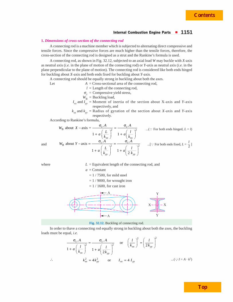
Internal Combustion Engine Parts 11511. Dimensions of cross-section of the connecting rod
A connecting rod is a machine member which is subjected to alternating direct compressive andtensile forces. Since the compressive forces are much higher than the tensile forces, therefore, thecross-section of the connecting rod is designed as a strut and the Rankine’s formula is used.
A connecting rod, as shown in Fig. 32.12, subjected to an axial load W may buckle with X-axisas neutral axis (i.e. in the plane of motion of the connecting rod) or Y-axis as neutral axis (i.e. in theplane perpendicular to the plane of motion). The connecting rod is considered like both ends hingedfor buckling about X-axis and both ends fixed for buckling about Y-axis.
A connecting rod should be equally strong in buckling about both the axes.Let A = Cross-sectional area of the connecting rod,
l = Length of the connecting rod,σc = Compressive yield stress,
WB = Buckling load,Ixx and Iyy = Moment of inertia of the section about X-axis and Y-axis
respectively, andkxx and kyy = Radius of gyration of the section about X-axis and Y-axis
respectively.According to Rankine’s formula,
B 2 2
. .about axis =
1 1
c c
xx xx
A AW X
L la a
k k
σ σ− =
⎛ ⎞ ⎛ ⎞+ +⎜ ⎟ ⎜ ⎟⎝ ⎠ ⎝ ⎠
...(Q For both ends hinged, L = l)
and B 2 2
. .about axis
1 12
c c
yy yy
A AW Y
L la a
k k
σ σ− = =
⎛ ⎞ ⎛ ⎞+ +⎜ ⎟ ⎜ ⎟
⎝ ⎠ ⎝ ⎠
...[Q For both ends fixed, L = 2l
]
where L = Equivalent length of the connecting rod, and
a = Constant
= 1 / 7500, for mild steel
= 1 / 9000, for wrought iron
= 1 / 1600, for cast iron
Fig. 32.12. Buckling of connecting rod.
In order to thave a connecting rod equally strong in buckling about both the axes, the bucklingloads must be equal, i.e.
22
2 2
. .or
21 1
2
c c
xx yy
xx yy
A A l lk kl la ak k
⎛ ⎞σ σ ⎛ ⎞= = ⎜ ⎟⎜ ⎟⎝ ⎠ ⎝ ⎠⎛ ⎞ ⎛ ⎞+ +⎜ ⎟ ⎜ ⎟⎝ ⎠ ⎝ ⎠
∴ 2 24 or 4xx yy xx yyk k I I= = ...(Q I = A · k2)
1152 A Textbook of Machine Design
This shows that the connecting rod is four timesstrong in buckling about Y-axis than about X-axis. IfIxx > 4 Iyy, then buckling will occur about Y- axis andif Ixx < 4 Iyy, buckling will occur about X-axis. Inactual practice, Ixx is kept slightly less than 4 Iyy. Itis usually taken between 3 and 3.5 and the connectingrod is designed for bucking about X-axis. The designwill always be satisfactory for buckling about Y-axis.
The most suitable section for the connectingrod is I-section with the proportions as shown inFig. 32.13 (a).
Let thickness of the flange and web of thesection = t
Width of the section, B = 4 t
and depth or height of the section,
H = 5t
From Fig. 32.13 (a), we find that area of the section,
A = 2 (4 t × t) + 3 t × t = 11 t2
Moment of inertia of the section about X-axis,
Ixx =3 3 41 419
4 (5 ) 3 (3 )12 12
t t t t t⎡ ⎤− =⎣ ⎦
and moment of inertia of the section about Y-axis,
Iyy = 3 3 41 1 1312 (4 ) (3 )
12 12 12t t t t t⎡ ⎤× × + =⎢ ⎥⎣ ⎦
∴419 12
3.212 131
xx
yy
II
= × =
Since the value of xx
yy
II
lies between 3 and 3.5, therefore, I-section chosen is quite satisfactory.
After deciding the proportions for I-section of the connecting rod, its dimensions are determinedby considering the buckling of the rod about X-axis (assuming both ends hinged) and applying theRankine’s formula. We know that buckling load,
WB = 2
.
1
c
xx
A
La
k
σ
⎛ ⎞+ ⎜ ⎟⎝ ⎠
The buckling load (WB) may be calculated by using the following relation, i.e.
WB = Max. gas force × Factor of safety
The factor of safety may be taken as 5 to 6.Notes : (a) The I-section of the connecting rod is used due to its lightness and to keep the inertia forces as lowas possible specially in case of high speed engines. It can also withstand high gas pressure.
(b) Sometimes a connecting rod may have rectangular section. For slow speed engines, circular sectionmay be used.
(c) Since connecting rod is manufactured by forging, therefore the sharp corner of I-section are roundedoff as shown in Fig. 32.13 (b) for easy removal of the section from dies.
Fig. 32.13. I-section of connecting rod.
Internal Combustion Engine Parts 1153The dimensions B = 4 t and H = 5 t, as obtained above by applying the Rankine’s formula,
are at the middle of the connecting rod. The width of the section (B) is kept constant throughout thelength of the connecting rod, but the depth or height varies. The depth near the small end (or pistonend) is taken as H1 = 0.75 H to 0.9H and the depth near the big end (or crank end) is takenH2 = 1.1H to 1.25H.
2. Dimensions of the crankpin at the big end and the piston pin at the small endSince the dimensions of the crankpin at the big end and the piston pin (also known as gudgeon
pin or wrist pin) at the small end are limited, therefore, fairly high bearing pressures have to beallowed at the bearings of these two pins.
The crankpin at the big endhas removable precision bearingshells of brass or bronze or steelwith a thin lining (1 mm or less)of bearing metal (such as tin, lead,babbit, copper, lead) on the innersurface of the shell. The allowablebearing pressure on the crankpindepends upon many factors suchas material of the bearing,viscosity of the lubricating oil,method of lubrication and thespace limitations.The value ofbearing pressure may be takenas 7 N/mm2 to 12.5 N/mm2
depending upon the material andmethod of lubrication used.
The piston pin bearing is usually a phosphor bronze bush of about 3 mm thickness and theallowable bearing pressure may be taken as 10.5 N/mm2 to 15 N/mm2.
Since the maximum load to be carried by the crankpin and piston pin bearings is the maximumforce in the connecting rod (FC), therefore the dimensions for these two pins are determined for themaximum force in the connecting rod (FC) which is taken equal to the maximum force on the pistondue to gas pressure (FL) neglecting the inertia forces.
We know that maximum gas force,
FL =2
4D
pπ × ...(i)
where D = Cylinder bore or piston diameter in mm, andp = Maximum gas pressure in N/mm2
Now the dimensions of the crankpin and piston pin are determined as discussed below :Let dc = Diameter of the crank pin in mm,
lc = Length of the crank pin in mm,pbc = Allowable bearing pressure in N/mm2, and
dp, lp and pbp = Corresponding values for the piston pin,We know that load on the crank pin
= Projected area × Bearing pressure= dc . lc . pbc ...(ii)
Similarly, load on the piston pin= dp . lp . pbp ...(iii)
Engine of a motorcyle.
1154 A Textbook of Machine Design
Equating equations (i) and (ii), we haveFL = dc · lc · pbc
Taking lc = 1.25 dc to 1.5 dc, the value of dc and lc are determined from the above expression.Again, equating equations (i) and (iii), we have
FL = dp · lp · pbp
Taking lp = 1.5 dp to 2 dp, the value of dp and lp are determined from the above expression.3. Size of bolts for securing the big end cap
The bolts and the big end cap are subjected to tensile force which corresponds to the inertiaforce of the reciprocating parts at the top dead centre on the exhaust stroke. We know that inertiaforce of the reciprocating parts,
∴ FI =2
Rcos 2
. . cos/
m rl r
θ⎛ ⎞ω θ +⎜ ⎟⎝ ⎠
We also know that at the top dead centre, the angle of inclination of the crank with the line ofstroke, θ = 0
∴ 2
I R . . 1r
F m rl
⎛ ⎞= ω +⎜ ⎟⎝ ⎠
where mR = Mass of the reciprocating parts in kg,ω = Angular speed of the engine in rad / s,r = Radius of the crank in metres, andl = Length of the connecting rod in metres.
The bolts may be made of high carbon steel or nickel alloy steel. Since the bolts are underrepeated stresses but not alternating stresses, therefore, a factor of safety may be taken as 6.
Let dcb = Core diameter of the bolt in mm,
tσ = Allowable tensile stress for the material of the bolts in MPa, and
nb = Number of bolts. Generally two bolts are used.∴ Force on the bolts
= 2( )4 cb t bd nπ σ ×
Internal Combustion Engine Parts 1155Equating the inertia force to the force on the bolts, we have
FI = 2( )4 cb t bd nπ σ ×
From this expression, dcb is obtained. The nominal or major diameter (db) of the bolt is given by
db =0.84
cbd
4. Thickness of the big end capThe thickness of the big end cap (tc) may be determined by treating the cap as a beam freely
supported at the cap bolt centres and loaded by the inertia force at the top dead centre on the exhauststroke (i.e. FI when θ = 0). This load is assumed to act in between the uniformly distributed load andthe centrally concentrated load. Therefore, the maximum bending moment acting on the cap will betaken as
MC = * I
6F x×
where x = Distance between the bolt centres.
= Dia. of crankpin or big end bearing (dc) + 2 × Thickness of bearingliner (3 mm) + Clearance (3 mm)
Let bc = Width of the cap in mm. It is equal to the length of the crankpin orbig end bearing (lc), and
bσ = Allowable bending stress for the material of the cap in MPa.
We know that section modulus for the cap,
ZC =2( )
6c cb t
∴ Bending stress, σb =C I I
2 2C
66 ( ) ( )c c c c
M F x F xZ b t b t
× ×= × =
From this expression, the value of tc is obtained.Note: The design of connecting rod should be checked for whipping stress (i.e. bending stress due to inertiaforce on the connecting rod).
Example 32.3. Design a connecting rod for an I.C. engine running at 1800 r.p.m. and developinga maximum pressure of 3.15 N/mm2. The diameter of the piston is 100 mm ; mass of the reciprocatingparts per cylinder 2.25 kg; length of connecting rod 380 mm; stroke of piston 190 mm and compressionratio 6 : 1. Take a factor of safety of 6 for the design. Take length to diameter ratio for big endbearing as 1.3 and small end bearing as 2 and the corresponding bearing pressures as 10 N/mm2
and 15 N/mm2. The density of material of the rod may be taken as 8000 kg/m3 and the allowablestress in the bolts as 60 N/mm2 and in cap as 80 N/mm2. The rod is to be of I-section for which youcan choose your own proportions.
Draw a neat dimensioned sketch showing provision for lubrication. Use Rankine formula forwhich the numerator constant may be taken as 320 N/mm2 and the denominator constant 1 / 7500.
* We know that the maximum bending moment for a simply or freely supported beam with a uniformlydistributed load of FI over a length x between the supports (In this case, x is the distance between the cap
bolt centres) is I .8
F x× When the load FI is assumed to act at the centre of the freely supported beam, then
the maximum bending moment is I .4
F x× Thus the maximum bending moment in between these two bending
moments I I I. . and is .8 4 6
F x F x F xi e
× × ×⎛ ⎞⎜ ⎟⎝ ⎠
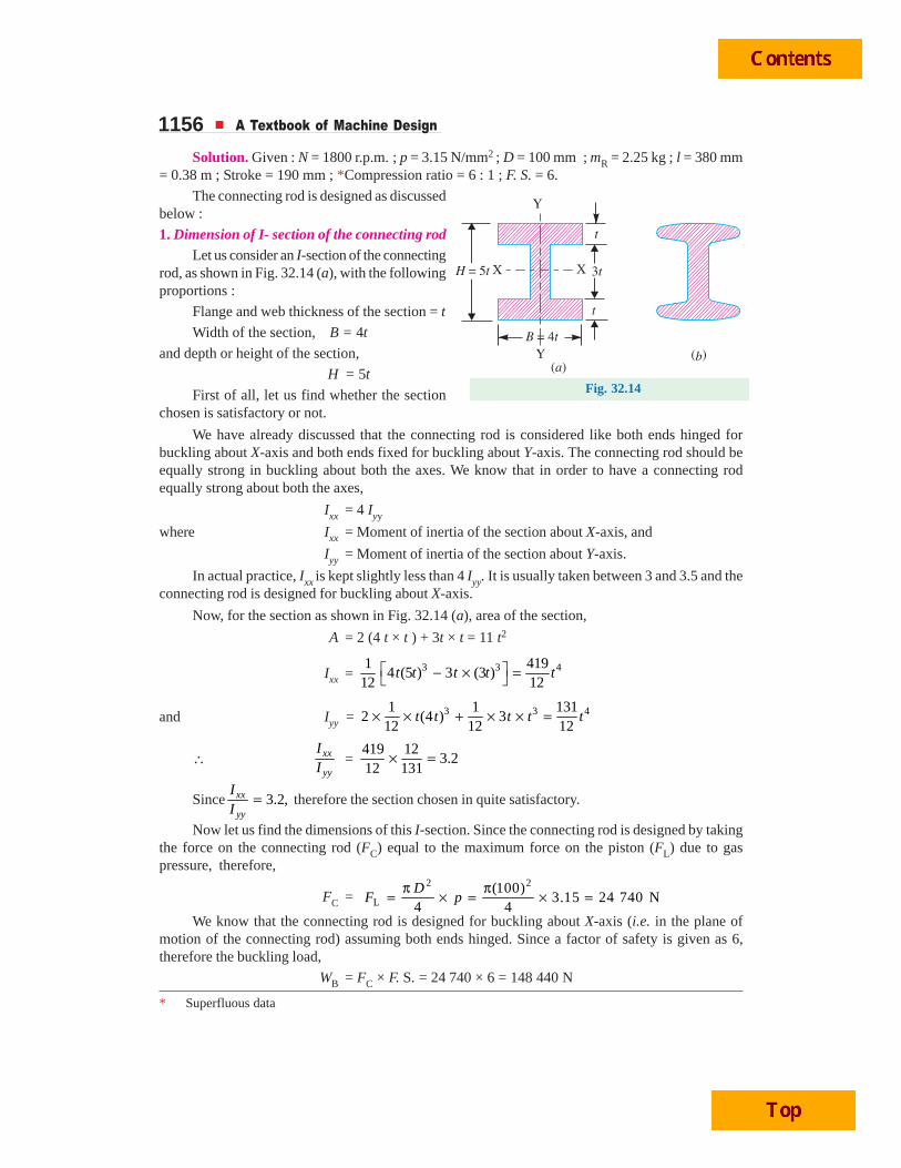
1156 A Textbook of Machine Design
Solution. Given : N = 1800 r.p.m. ; p = 3.15 N/mm2 ; D = 100 mm ; mR = 2.25 kg ; l = 380 mm= 0.38 m ; Stroke = 190 mm ; *Compression ratio = 6 : 1 ; F. S. = 6.
The connecting rod is designed as discussedbelow :
1. Dimension of I- section of the connecting rodLet us consider an I-section of the connecting
rod, as shown in Fig. 32.14 (a), with the followingproportions :
Flange and web thickness of the section = t
Width of the section, B = 4t
and depth or height of the section,
H = 5t
First of all, let us find whether the sectionchosen is satisfactory or not.
We have already discussed that the connecting rod is considered like both ends hinged forbuckling about X-axis and both ends fixed for buckling about Y-axis. The connecting rod should beequally strong in buckling about both the axes. We know that in order to have a connecting rodequally strong about both the axes,
Ixx = 4 Iyy
where Ixx = Moment of inertia of the section about X-axis, and
Iyy = Moment of inertia of the section about Y-axis.
In actual practice, Ixx is kept slightly less than 4 Iyy. It is usually taken between 3 and 3.5 and theconnecting rod is designed for buckling about X-axis.
Now, for the section as shown in Fig. 32.14 (a), area of the section,
A = 2 (4 t × t ) + 3t × t = 11 t2
Ixx = 3 3 41 4194 (5 ) 3 (3 )
12 12t t t t t⎡ ⎤− × =⎣ ⎦
and Iyy = 3 3 41 1 1312 (4 ) 3
12 12 12t t t t t× × + × × =
∴ xx
yy
II
=419 12
3.212 131
× =
Since 3.2,xx
yy
II
= therefore the section chosen in quite satisfactory.
Now let us find the dimensions of this I-section. Since the connecting rod is designed by takingthe force on the connecting rod (FC) equal to the maximum force on the piston (FL) due to gaspressure, therefore,
FC =2 2
L(100)
3.15 24 740 N4 4D
F pπ π= × = × =
We know that the connecting rod is designed for buckling about X-axis (i.e. in the plane ofmotion of the connecting rod) assuming both ends hinged. Since a factor of safety is given as 6,therefore the buckling load,
WB = FC × F. S. = 24 740 × 6 = 148 440 N
Fig. 32.14
* Superfluous data
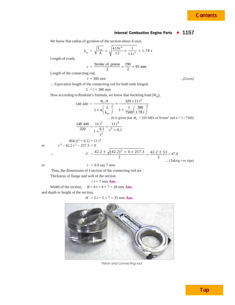
Internal Combustion Engine Parts 1157We know that radius of gyration of the section about X-axis,
kxx =4
2
419 11.78
12 11xxI t
tA t
= × =
Length of crank,
r =Stroke of piston 190
95 mm2 2
= =
Length of the connecting rod,
l = 380 mm ...(Given)
∴ Equivalent length of the connecting rod for both ends hinged,
L = l = 380 mm
Now according to Rankine’s formula, we know that buckling load (WB),
148 440 =2
2 2
. 320 11
1 38011
7500 1.78
c
xx
A t
La
tk
σ ×=⎛ ⎞ ⎛ ⎞++ ⎜ ⎟⎜ ⎟ ⎝ ⎠⎝ ⎠
... (It is given that cσ = 320 MPa or N/mm2 and a = 1 / 7500)
2 4
2
2
148 440 11 11320 6.1 6.11
t t
tt
= =++
464 (t2 + 6.1) = 11 t4
or t 4 – 42.2 t 2 – 257.3 = 0
∴ t2 =242.2 (42.2) 4 257.3 42.2 53
2 2± + × ±= = 47.6
... (Taking +ve sign)or t = 6.9 say 7 mm
Thus, the dimensions of I-section of the connecting rod are :
Thickness of flange and web of the section
= t = 7 mm Ans.Width of the section, B = 4 t = 4 × 7 = 28 mm Ans.
and depth or height of the section,
H = 5 t = 5 × 7 = 35 mm Ans.
Piston and connecting rod.
1158 A Textbook of Machine Design
These dimensions are at the middle of the connecting rod. The width (B) is kept constant through-out the length of the rod, but the depth (H) varies. The depth near the big end or crank end is kept as 1.1Hto 1.25H and the depth near the small end or piston end is kept as 0.75H to 0.9H. Let us take
Depth near the big end,
H1 = 1.2H = 1.2 × 35 = 42 mm
and depth near the small end,
H2 = 0.85H = 0.85 × 35 = 29.75 say 30 mm
∴ Dimensions of the section near the big end
= 42 mm × 28 mm Ans.
and dimensions of the section near the small end
= 30 mm × 28 mm Ans.
Since the connecting rod is manufactured by forging, therefore the sharp corners of I-sectionare rounded off, as shown in Fig. 32.14 (b), for easy removal of the section from the dies.
2. Dimensions of the crankpin or the big end bearing and piston pin or small end bearing
Let dc = Diameter of the crankpin or big end bearing,
lc = length of the crankpin or big end bearing = 1.3 dc ...(Given)
pbc = Bearing pressure = 10 N/mm2 ...(Given)
We know that load on the crankpin or big end bearing
= Projected area × Bearing pressure
= dc .lc . pbc = dc × 1.3 dc × 10 = 13 (dc)2
Since the crankpin or the big end bearing is designed for the maximum gas force (FL), therefore,equating the load on the crankpin or big end bearing to the maximum gas force, i.e.
13 (dc)2 = FL = 24 740 N
∴ (dc )2 = 24 740 / 13 = 1903 or dc = 43.6 say 44 mm Ans.and lc = 1.3 dc = 1.3 × 44 = 57.2 say 58 mm Ans.
The big end has removable precision bearing shells of brass or bronze or steel with a thin lining(1mm or less) of bearing metal such as babbit.
Again, let dp = Diameter of the piston pin or small end bearing,
lp = Length of the piston pin or small end bearing = 2dp ...(Given)
pbp = Bearing pressure = 15 N/mm2 ..(Given)
We know that the load on the piston pin or small end bearing
= Project area × Bearing pressure
= dp . lp . pbp = dp × 2 dp × 15 = 30 (dp)2
Since the piston pin or the small end bearing is designed for the maximum gas force (FL),therefore, equating the load on the piston pin or the small end bearing to the maximum gas force,
i.e.
30 (dp)2 = 24 740 N
∴ (dp)2 = 24 740 / 30 = 825 or dp = 28.7 say 29 mm Ans.
and lp = 2 dp = 2 × 29 = 58 mm Ans.The small end bearing is usually a phosphor bronze bush of about 3 mm thickness.
Internal Combustion Engine Parts 11593. Size of bolts for securing the big end cap
Let dcb = Core diameter of the bolts,
tσ = Allowable tensile stress for the material of the bolts
= 60 N/mm2 ...(Given)
and nb = Number of bolts. Generally two bolts are used.We know that force on the bolts
= 2 2 2( ) ( ) 60 2 94.26 ( )4 4cb t b cb cbd n d dπ πσ × = × =
The bolts and the big end cap are subjected to tensile force which corresponds to the inertiaforce of the reciprocating parts at the top dead centre on the exhaust stroke. We know that inertiaforce of the reciprocating parts,
FI = mR . ω2 . r cos 2
cos/l r
θ⎛ ⎞θ +⎜ ⎟⎝ ⎠
We also know that at top dead centre on the exhaust stroke, θ = 0.
∴ FI = mR . ω2 . r2
2 1800 0.0951 2.25 0.095 1 N
60 0.38rl
π ×⎛ ⎞ ⎛ ⎞ ⎛ ⎞+ = +⎜ ⎟ ⎜ ⎟ ⎜ ⎟⎝ ⎠ ⎝ ⎠ ⎝ ⎠
= 9490 N
Equating the inertia force to the force on the bolts, we have
9490 = 94.26 (dcb)2 or (dcb)
2 = 9490 / 94.26 = 100.7
∴ dcb = 10.03 mm
and nominal diameter of the bolt,
10.0311.94
0.84 0.84cb
bd
d = = =say 12 mm Ans.
4. Thickness of the big end cap
Let tc = Thickness of the big end cap,
bc = Width of the big end cap. It istaken equal to the length of thecrankpin or big end bearing (lc)
= 58 mm (calculated above)
σb = Allowable bending stress for thematerial of the cap
= 80 N/mm2 ...(Given)
The big end cap is designed as a beam freelysupported at the cap bolt centres and loaded by the inertiaforce at the top dead centre on the exhaust stroke (i.e. FIwhen θ = 0). Since the load is assumed to act in betweenthe uniformly distributed load and the centrallyconcentrated load, therefore, maximum bending momentis taken as
MC = I
6F x×
where x = Distance between the bolt centres
1160 A Textbook of Machine Design
= Dia. of crank pin or big end bearing + 2 × Thickness of bearingliner + Nominal dia. of bolt + Clearance
= (dc + 2 × 3 + db + 3) mm = 44 + 6 + 12 + 3 = 65 mm
∴ Maximum bending moment acting on the cap,
MC = I 9490 65102 810
6 6× ×= =
F xN-mm
Section modulus for the cap
ZC =2 2
2( ) 58( )9 .7 ( )
6 6= =c c c
cb t t
t
We know that bending stress ( σb ),
C2 2
C
102 810 10 60080
9.7 ( ) ( )c c
MZ t t
= = =
∴ (tc)2 = 10 600 / 80 = 132.5 or tc = 11.5 mm Ans.
Let us now check the design for the induced bending stress due to inertia bending forces on theconnecting rod (i.e. whipping stress).
We know that mass of the connecting rod per metre length,
m1 = Volume × density = Area × length × density
= A × l × ρ = 11t2 × l × ρ ...(Q A = 11t2)
= 11(0.007)2 (0.38) 8000 = 1.64 kg...[Q ρ = 8 000 kg /m3 (given)]
∴ Maximum bending moment,
Mmax = m . ω2 . r × 9 3
l = m1 . ω
2 . r × 2
9 3
l...(Q m = m1· l)
=2 22 1800 (0.38)
1.64 (0.095) 51.360 9 3
π ×⎛ ⎞ =⎜ ⎟⎝ ⎠
N-m
= 51 300 N-mm
and section modulus,4
3419 213.97
5 / 2 12 5xx
xxI t
Z tt t
= = × = =13.97 × 73 = 4792 mm3
∴ Maximum bending stress (induced ) due to inertia bending forces or whipping stress,
2( )
51 30010.7 N / mm
4792max
b maxxx
MZ
σ = = =
Since the maximum bending stress induced is less than the allowable bending stress of80 N/mm2, therefore the design is safe.
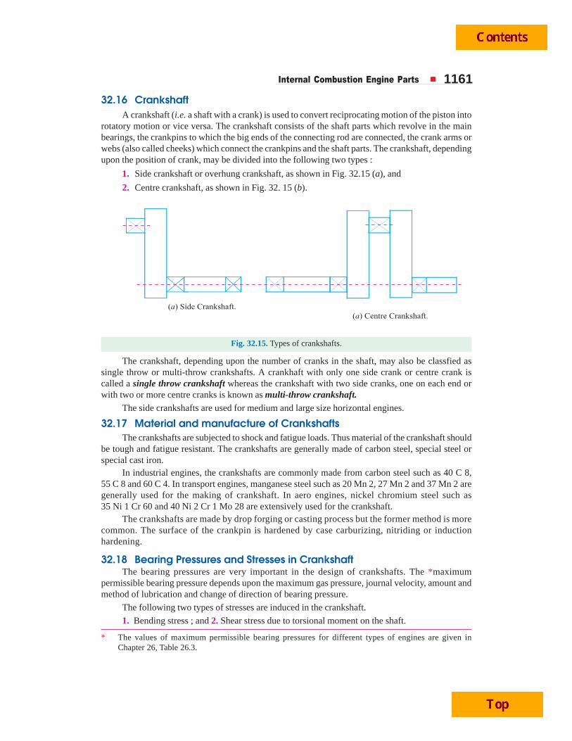
Internal Combustion Engine Parts 1161
32.16 CrankshaftA crankshaft (i.e. a shaft with a crank) is used to convert reciprocating motion of the piston into
rotatory motion or vice versa. The crankshaft consists of the shaft parts which revolve in the mainbearings, the crankpins to which the big ends of the connecting rod are connected, the crank arms orwebs (also called cheeks) which connect the crankpins and the shaft parts. The crankshaft, dependingupon the position of crank, may be divided into the following two types :
1. Side crankshaft or overhung crankshaft, as shown in Fig. 32.15 (a), and
2. Centre crankshaft, as shown in Fig. 32. 15 (b).
Fig. 32.15. Types of crankshafts.
The crankshaft, depending upon the number of cranks in the shaft, may also be classfied assingle throw or multi-throw crankshafts. A crankhaft with only one side crank or centre crank iscalled a single throw crankshaft whereas the crankshaft with two side cranks, one on each end orwith two or more centre cranks is known as multi-throw crankshaft.
The side crankshafts are used for medium and large size horizontal engines.
32.17 Material and manufacture of CrankshaftsThe crankshafts are subjected to shock and fatigue loads. Thus material of the crankshaft should
be tough and fatigue resistant. The crankshafts are generally made of carbon steel, special steel orspecial cast iron.
In industrial engines, the crankshafts are commonly made from carbon steel such as 40 C 8,55 C 8 and 60 C 4. In transport engines, manganese steel such as 20 Mn 2, 27 Mn 2 and 37 Mn 2 aregenerally used for the making of crankshaft. In aero engines, nickel chromium steel such as35 Ni 1 Cr 60 and 40 Ni 2 Cr 1 Mo 28 are extensively used for the crankshaft.
The crankshafts are made by drop forging or casting process but the former method is morecommon. The surface of the crankpin is hardened by case carburizing, nitriding or inductionhardening.
32.18 Bearing Pressures and Stresses in CrankshaftThe bearing pressures are very important in the design of crankshafts. The *maximum
permissible bearing pressure depends upon the maximum gas pressure, journal velocity, amount andmethod of lubrication and change of direction of bearing pressure.
The following two types of stresses are induced in the crankshaft.
1. Bending stress ; and 2. Shear stress due to torsional moment on the shaft.
* The values of maximum permissible bearing pressures for different types of engines are given inChapter 26, Table 26.3.
1162 A Textbook of Machine Design
Most crankshaft failures are caused by a progressive fracture due to repeated bending or reversedtorsional stresses. Thus the crankshaft is under fatigue loading and, therefore, its design should bebased upon endurance limit. Since the failure of a crankshaft is likely to cause a serious enginedestruction and neither all the forces nor all the stresses acting on the crankshaft can be determinedaccurately, therefore a high factor of safety from 3 to 4, based on the endurance limit, is used.
The following table shows the allowable bending and shear stresses for some commonly usedmaterials for crankshafts :
Table 32.2. Allowable bending and shear stresses.
Material Endurance limit in MPa Allowable stress in MPa
Bending Shear Bending Shear
Chrome nickel 525 290 130 to 175 72.5 to 97
Carbon steel and cast steel 225 124 56 to 75 31 to 42
Alloy cast iron 140 140 35 to 47 35 to 47
32.19 Design Procedure for CrankshaftThe following procedure may be adopted for designing a crankshaft.
1. First of all, find the magnitude of the various loads on the crankshaft.
2. Determine the distances between the supports and their position with respect to the loads.
3. For the sake of simplicity and also for safety, the shaft is considered to be supported at thecentres of the bearings and all the forces and reactions to be acting at these points. The distancesbetween the supports depend on the length of the bearings, which in turn depend on the diameter ofthe shaft because of the allowable bearing pressures.
4. The thickness of the cheeks or webs is assumed to be from 0.4 ds to 0.6 ds, where ds is thediameter of the shaft. It may also be taken as 0.22D to 0.32 D, where D is the bore of cylinder in mm.
5. Now calculate the distances between the supports.
6. Assuming the allowable bending and shear stresses, determine the main dimensions of thecrankshaft.Notes: 1. The crankshaft must be designed or checked for at least two crank positions. Firstly, when the crank-shaft is subjected to maximum bending moment and secondly when the crankshaft is subjected to maximumtwisting moment or torque.
2. The additional moment due to weight of flywheel, belt tension and other forces must be considered.
3. It is assumed that the effect of bending moment does not exceed two bearings between which a force isconsidered.
32.20 Design of Centre CrankshaftWe shall design the centre crankshaft by considering the two crank possitions, i.e. when the
crank is at dead centre (or when the crankshaft is subjected to maximum bending moment) and whenthe crank is at angle at which the twisting moment is maximum. These two cases are discussed indetail as below :
1. When the crank is at dead centre. At this position of the crank, the maximum gas pressure onthe piston will transmit maximum force on the crankpin in the plane of the crank causing only bendingof the shaft. The crankpin as well as ends of the crankshaft will be only subjected to bending moment.Thus, when the crank is at the dead centre, the bending moment on the shaft is maximum and thetwisting moment is zero.
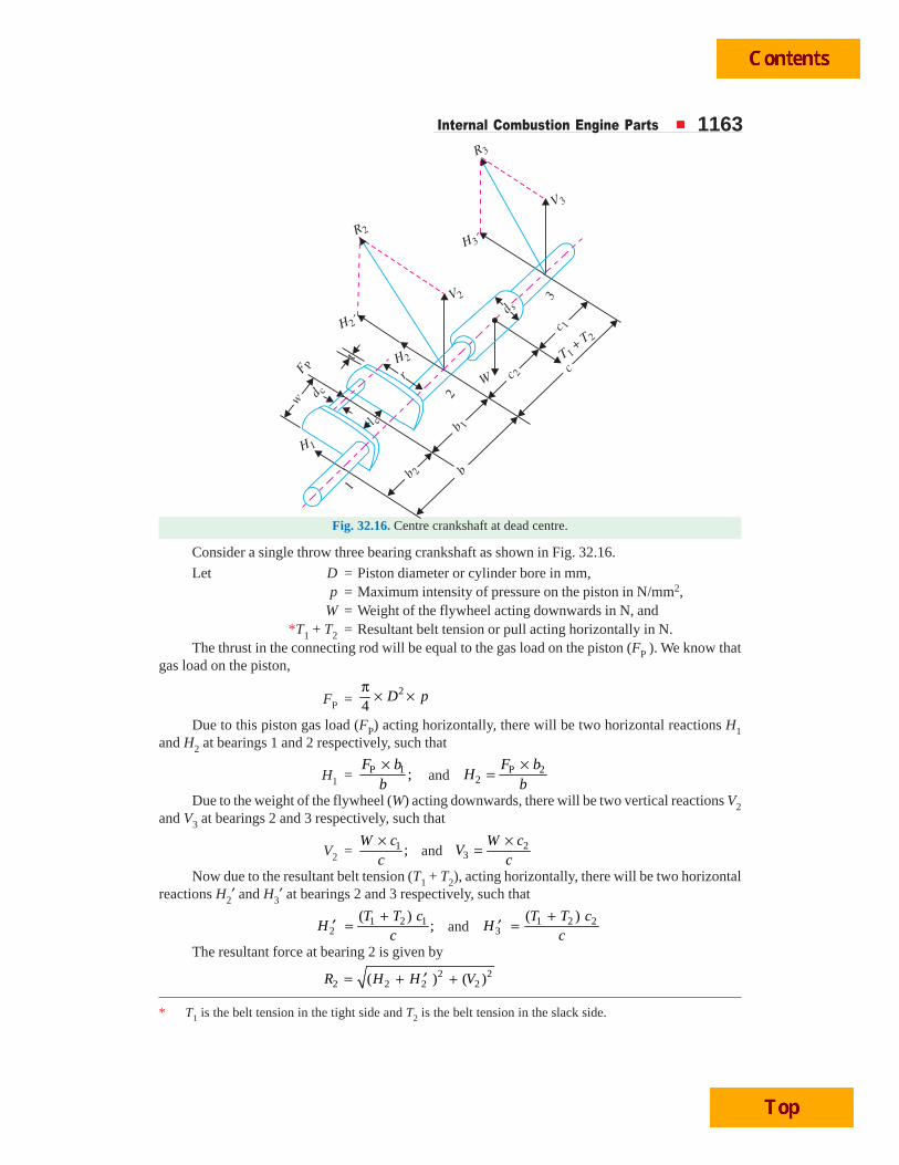
Internal Combustion Engine Parts 1163
Fig. 32.16. Centre crankshaft at dead centre.
Consider a single throw three bearing crankshaft as shown in Fig. 32.16.
Let D = Piston diameter or cylinder bore in mm,p = Maximum intensity of pressure on the piston in N/mm2,
W = Weight of the flywheel acting downwards in N, and*T1 + T2 = Resultant belt tension or pull acting horizontally in N.
The thrust in the connecting rod will be equal to the gas load on the piston (FP ). We know thatgas load on the piston,
FP =2
4D p
π × ×
Due to this piston gas load (FP) acting horizontally, there will be two horizontal reactions H1and H2 at bearings 1 and 2 respectively, such that
H1 = P 1 ;F b
b×
and P 22
F bH
b×
=
Due to the weight of the flywheel (W) acting downwards, there will be two vertical reactions V2and V3 at bearings 2 and 3 respectively, such that
V2 = 1 ;W c
c×
and 23
W cV
c×
=
Now due to the resultant belt tension (T1 + T2), acting horizontally, there will be two horizontalreactions H2′ and H3′ at bearings 2 and 3 respectively, such that
1 2 12
( );
T T cH
c+
′ = and 1 2 23
( )T T cH
c+
′ =
The resultant force at bearing 2 is given by2 2
2 2 2 2( ) ( )R H H V= + ′ +
* T1 is the belt tension in the tight side and T2 is the belt tension in the slack side.
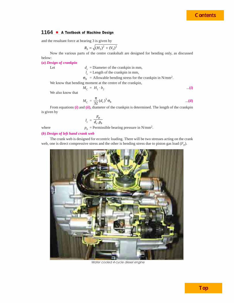
1164 A Textbook of Machine Design
and the resultant force at bearing 3 is given by2 2
3 3 3( ) ( )R H V= +Now the various parts of the centre crankshaft are designed for bending only, as discussed
below:(a) Design of crankpin
Let dc = Diameter of the crankpin in mm,lc = Length of the crankpin in mm,
bσ = Allowable bending stress for the crankpin in N/mm2.We know that bending moment at the centre of the crankpin,
MC = H1 · b2 ...(i)We also know that
MC = 3( )32 c bdπ σ ...(ii)
From equations (i) and (ii), diameter of the crankpin is determined. The length of the crankpinis given by
Ic =P
.c b
Fd p
where pb = Permissible bearing pressure in N/mm2.
(b) Design of left hand crank webThe crank web is designed for eccentric loading. There will be two stresses acting on the crank
web, one is direct compressive stress and the other is bending stress due to piston gas load (FP).
Water cooled 4-cycle diesel engine
Internal Combustion Engine Parts 1165The thickness (t) of the crank web is given empirically as
t = 0.4 ds to 0.6 ds
= 0.22D to 0.32D
= 0.65 dc + 6.35 mmwhere ds = Shaft diameter in mm,
D = Bore diameter in mm, anddc = Crankpin diameter in mm,
The width of crank web (w) is taken asw = 1.125 dc + 12.7 mm
We know that maximum bending moment on the crank web,
1 2 2 2cl t
M H b⎛ ⎞= − −⎜ ⎟⎝ ⎠
and section modulus, 21.
6Z w t= ×
∴ Bending stress,1 2
2
62 2
.
c
b
l tH b
MZ w t
⎛ ⎞− −⎜ ⎟⎝ ⎠σ = =
and direct compressive stress on the crank web,
1
.cH
w tσ =
∴ Total stress on the crank web
= Bending stress + Direct stress = b cσ + σ
=1 2
12
62 2
..
cl tH b
Hw tw t
⎛ ⎞− −⎜ ⎟⎝ ⎠+
This total stress should be less than the permissible bending stress.(c) Design of right hand crank web
The dimensions of the right hand crank web (i.e. thickness and width) are made equal to lefthand crank web from the balancing point of view.(d) Design of shaft under the flywheel
Let ds = Diameter of shaft in mm.We know that bending moment due to the weight of flywheel,
MW = V3 . c1
and bending moment due to belt tension,MT = H3′ . c1
These two bending moments act at right angles to each other. Therefore, the resultant bendingmoment at the flywheel location,
2 2 2 2S W T 3 1 3 1( ) ( ) ( · ) ( · )M M M V c H c= + = + ... (i)
We also know that the bending moment at the shaft,
3S ( )
32 s bM dπ
= σ ... (ii)
where bσ = Allowable bending stress in N/mm2.
From equations (i) and (ii), we may determine the shaft diameter (ds).
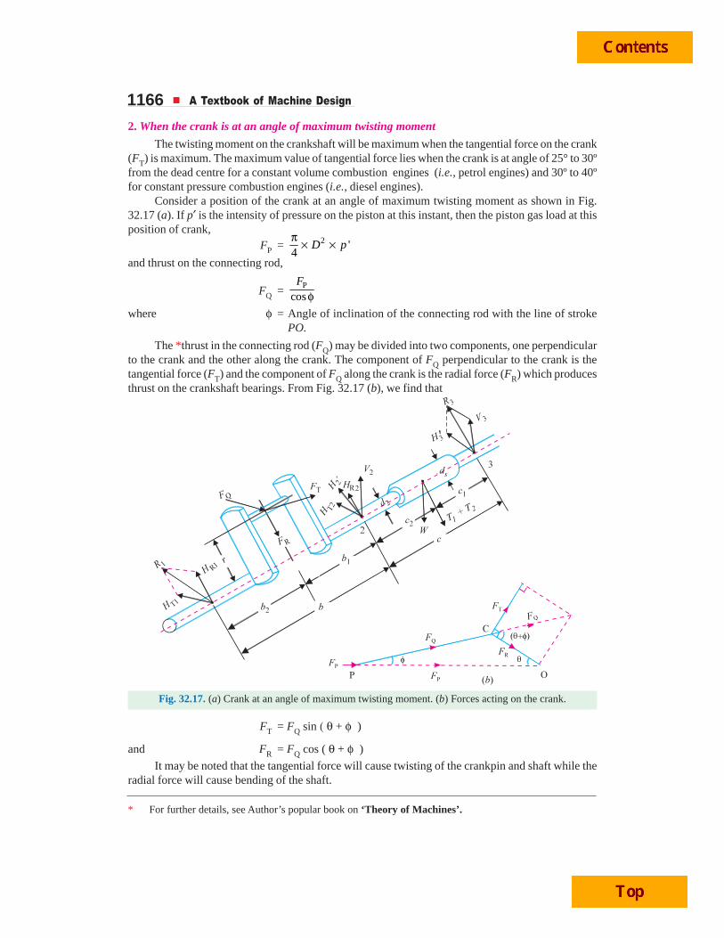
1166 A Textbook of Machine Design
2. When the crank is at an angle of maximum twisting moment
The twisting moment on the crankshaft will be maximum when the tangential force on the crank(FT) is maximum. The maximum value of tangential force lies when the crank is at angle of 25° to 30ºfrom the dead centre for a constant volume combustion engines (i.e., petrol engines) and 30º to 40ºfor constant pressure combustion engines (i.e., diesel engines).
Consider a position of the crank at an angle of maximum twisting moment as shown in Fig.32.17 (a). If p′ is the intensity of pressure on the piston at this instant, then the piston gas load at thisposition of crank,
FP = 2 '4
D pπ × ×
and thrust on the connecting rod,
FQ =P
cosF
φwhere φ = Angle of inclination of the connecting rod with the line of stroke
PO.
The *thrust in the connecting rod (FQ) may be divided into two components, one perpendicularto the crank and the other along the crank. The component of FQ perpendicular to the crank is thetangential force (FT) and the component of FQ along the crank is the radial force (FR) which producesthrust on the crankshaft bearings. From Fig. 32.17 (b), we find that
Fig. 32.17. (a) Crank at an angle of maximum twisting moment. (b) Forces acting on the crank.
FT = FQ sin ( θ + φ )
and FR = FQ cos ( θ + φ )
It may be noted that the tangential force will cause twisting of the crankpin and shaft while theradial force will cause bending of the shaft.
* For further details, see Author’s popular book on ‘Theory of Machines’.
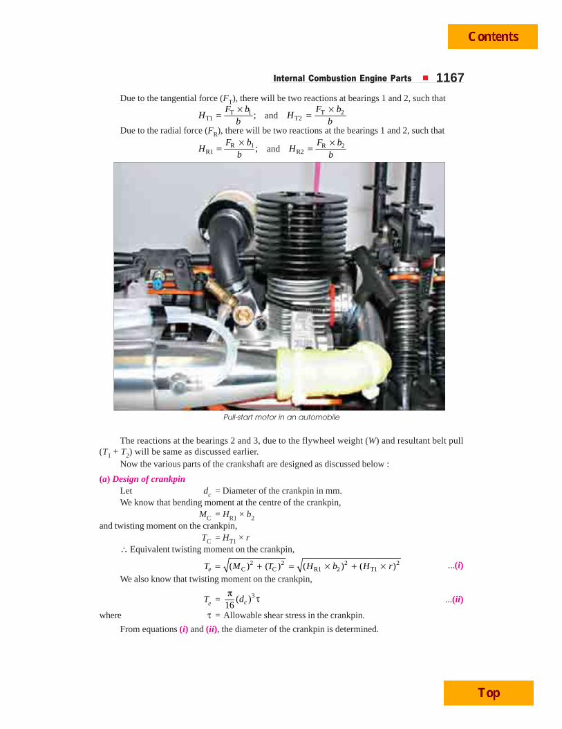
Internal Combustion Engine Parts 1167Due to the tangential force (FT), there will be two reactions at bearings 1 and 2, such that
T 1T1 ;
F bH
b×
= and T 2T2
F bH
b×
=
Due to the radial force (FR), there will be two reactions at the bearings 1 and 2, such that
R 1R1 ;
F bH
b×
= and R 2R2
F bH
b×
=
The reactions at the bearings 2 and 3, due to the flywheel weight (W) and resultant belt pull(T1 + T2) will be same as discussed earlier.
Now the various parts of the crankshaft are designed as discussed below :
(a) Design of crankpinLet dc = Diameter of the crankpin in mm.We know that bending moment at the centre of the crankpin,
MC = HR1 × b2and twisting moment on the crankpin,
TC = HT1 × r∴ Equivalent twisting moment on the crankpin,
2 2 2 2C C R1 2 T1( ) ( ) ( ) ( )eT M T H b H r= + = × + × ...(i)
We also know that twisting moment on the crankpin,
Te = 3( )16 cdπ τ ...(ii)
where τ = Allowable shear stress in the crankpin.
From equations (i) and (ii), the diameter of the crankpin is determined.
Pull-start motor in an automobile
1168 A Textbook of Machine Design
(b) Design of shaft under the flywheel
Let ds = Diameter of the shaft in mm.
We know that bending moment on the shaft,
MS = R3 × c1
and twisting moment on the shaft,
TS = FT × r
∴ Equivalent twisting moment on the shaft,
Te = 2 2 2 2S S 3 1 T( ) ( ) ( ) ( )M T R c F r+ = × + × ... (i)
We also know that equivalent twisting moment on the shaft,
Te = 3( )16 sdπ τ ... (ii)
where τ = Allowable shear stress in the shaft.
From equations (i) and (ii), the diameter of the shaft is determined.
(c) Design of shaft at the juncture of right hand crank arm
Let ds1 = Diameter of the shaft at the juncture of right hand crank arm.
We know that bending moment at the juncture of the right hand crank arm,
MS1 = 1 2 Q2 2 2 2c cl lt t
R b F⎛ ⎞ ⎛ ⎞+ + − +⎜ ⎟ ⎜ ⎟⎝ ⎠ ⎝ ⎠
and the twisting moment at the juncture of the right hand crank arm,
TS1 = FT × r
∴ Equivalent twisting moment at the juncture of the right hand crank arm,
Te = 2 2S1 S1( ) ( )M T+ ... (i)
We also know that equivalent twisting moment,
Te = 31( )
16 sdπ τ ... (ii)
where τ = Allowable shear stress in the shaft.
From equations (i) and (ii), the diameter of the shaft at the juncture of the right hand crank armis determined.
(d) Design of right hand crank web
The right hand crank web is subjected to the following stresses:
(i) Bending stresses in two planes normal to each other, due to the radial and tangentialcomponents of FQ,
(ii) Direct compressive stress due to FR, and
(iii) Torsional stress.
The bending moment due to the radial component of FQ is given by,
MR = R2 1 2 2cl t
H b⎛ ⎞− −⎜ ⎟⎝ ⎠
... (i)
We also know that MR = 2R R
1.
6b bZ w tσ × = σ × × ... (ii)
Internal Combustion Engine Parts 1169
where Rbσ = Bending stress in the radial direction, and
Z = Section modulus = 21·
6w t×
From equations (i) and (ii), the value of bending stress σbR is determined.
The bending moment due to the tangential component of FQ is maximum at the juncture ofcrank and shaft. It is given by
MT =1
T 2sd
F r⎡ ⎤−⎢ ⎥⎣ ⎦
... (iii)
where ds1 = Shaft diameter at juncture of right hand crank arm, i.e. atbearing 2.
We also know that MT = 2T T
1.
6b bZ t wσ × = σ × × ... (iv)
where σbT = Bending stress in tangential direction.From equations (iii) and (iv), the value of bending stress σbT is determined.The direct compressive stress is given by,
σd =R
2 .Fw t
The maximum compressive stress (σc) will occur at the upper left corner of the cross-section ofthe crank.
∴ σc = σbR + σbT + σdNow, the twisting moment on the arm,
T = T1 2 T T2 12 2 2c c cl l l
H b F H b⎛ ⎞ ⎛ ⎞+ − × = −⎜ ⎟ ⎜ ⎟⎝ ⎠ ⎝ ⎠
We know that shear stress on the arm,
τ = 2P
4.5
.
T TZ w t
=
where ZP = Polar section modulus = 2.
4.5w t
∴ Maximum or total combined stress,
(σc)max = 2 21( ) 4
2 2c
cσ
+ σ + τ
Snow blower on a railway track
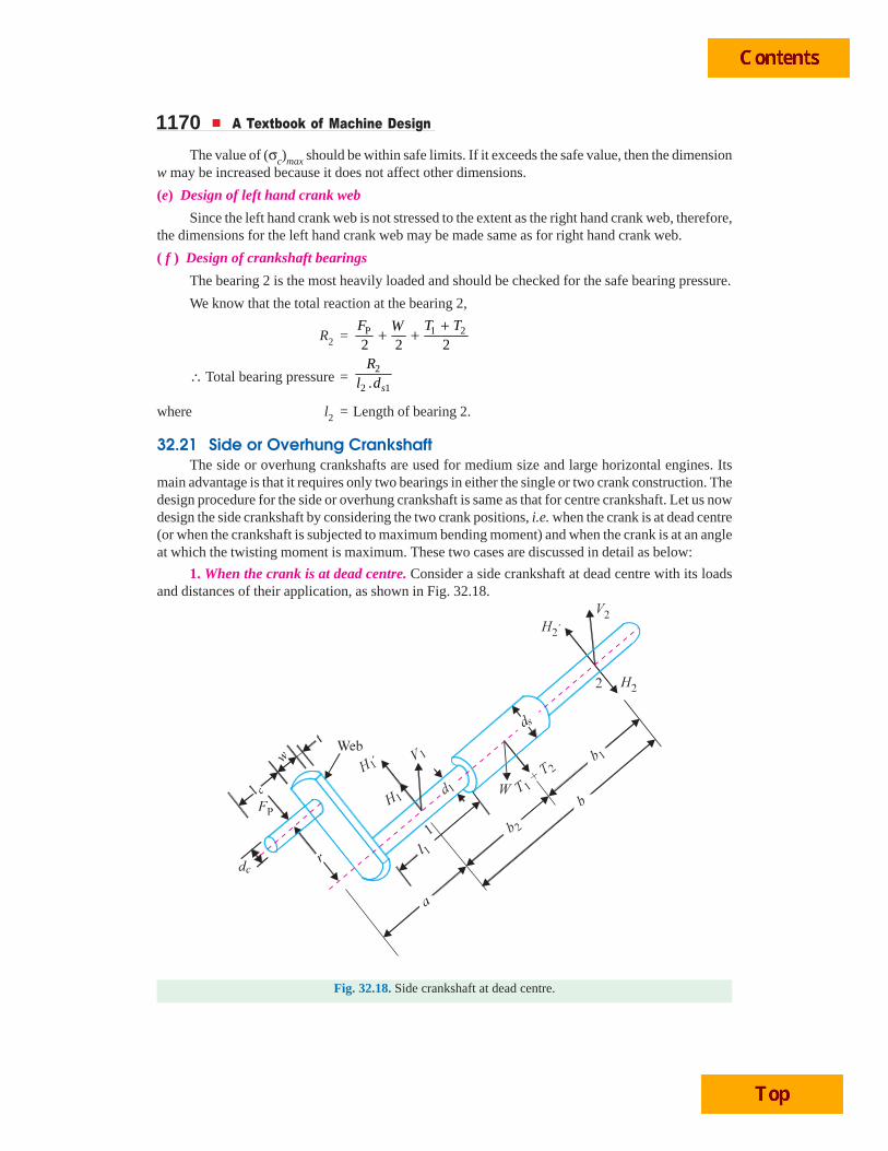
1170 A Textbook of Machine Design
The value of (σc)max should be within safe limits. If it exceeds the safe value, then the dimensionw may be increased because it does not affect other dimensions.
(e) Design of left hand crank web
Since the left hand crank web is not stressed to the extent as the right hand crank web, therefore,the dimensions for the left hand crank web may be made same as for right hand crank web.
( f ) Design of crankshaft bearings
The bearing 2 is the most heavily loaded and should be checked for the safe bearing pressure.
We know that the total reaction at the bearing 2,
R2 = P 1 2
2 2 2F T TW +
+ +
∴ Total bearing pressure =2
2 1. s
Rl d
where l2 = Length of bearing 2.
32.21 Side or Overhung CrankshaftThe side or overhung crankshafts are used for medium size and large horizontal engines. Its
main advantage is that it requires only two bearings in either the single or two crank construction. Thedesign procedure for the side or overhung crankshaft is same as that for centre crankshaft. Let us nowdesign the side crankshaft by considering the two crank positions, i.e. when the crank is at dead centre(or when the crankshaft is subjected to maximum bending moment) and when the crank is at an angleat which the twisting moment is maximum. These two cases are discussed in detail as below:
1. When the crank is at dead centre. Consider a side crankshaft at dead centre with its loadsand distances of their application, as shown in Fig. 32.18.
Fig. 32.18. Side crankshaft at dead centre.
Internal Combustion Engine Parts 1171Let D = Piston diameter or cylinder bore in mm,
p = Maximum intensity of pressure on the piston in N/mm2,
W = Weight of the flywheel acting downwards in N, and
T1 + T2 = Resultant belt tension or pull acting horizontally in N.
We know that gas load on the piston,
FP =2
4D p
π × ×
Due to this piston gas load (FP) acting horizontally, there will be two horizontal reactions H1andH2 at bearings 1 and 2 respectively, such that
H1 = P ( )F a bb
+; and H2 = PF a
b×
Due to the weight of the flywheel (W) acting downwards, there will be two vertical reactions V1and V2 at bearings l and 2 respectively, such that
V1 = 1.W bb
; and V2 = 2.W bb
Now due to the resultant belt tension (T1 + T2) acting horizontally, there will be two horizontalreactions H1′ and H2′ at bearings 1 and 2 respectively, such that
H1′ = 1 2 1( )T T bb
+; and H2′ = 1 2 2( )T T b
b+
The various parts of the side crankshaft, when the crank is at dead centre, are now designed asdiscussed below:
(a) Design of crankpin. The dimensions of the crankpin are obtained by considering the crank-pin in bearing and then checked for bending stress.
Let dc = Diameter of the crankpin in mm,
lc = Length of the crankpin in mm, and
pb = Safe bearing pressure on the pin in N/mm2. It may be between9.8 to 12.6 N/mm2.
We know that FP = dc . lc . pb
From this expression, the values of dc and lcmay be obtained. The length of crankpin is usuallyfrom 0.6 to 1.5 times the diameter of pin.
The crankpin is now checked for bendingstress. If it is assumed that the crankpin acts as acantilever and the load on the crankpin is uniformlydistributed, then maximum bending moment will
be P
2cF l×
. But in actual practice, the bearing
pressure on the crankpin is not uniformlydistributed and may, therefore, give a greater value
of bending moment ranging between P
2cF l×
and
P cF l× . So, a mean value of bending moment, i.e.
P34 cF l× may be assumed.
Close-up view of an automobile piston
1172 A Textbook of Machine Design
∴ Maximum bending moment at the crankpin,
M = ×P34 cF l ... (Neglecting pin collar thickness)
Section modulus for the crankpin,
Z = 3( )32π
cd
∴ Bending stress induced,
σb = M / Z
This induced bending stress should be within the permissible limits.
(b) Design of bearings. The bending moment at the centre of the bearing 1 is given by
M = FP (0.75 lc + t + 0.5 l1) ...(i)
where lc = Length of the crankpin,
t = Thickness of the crank web = 0.45 dc to 0.75 dc, and
l1 = Length of the bearing = 1.5 dc to 2 dc.
We also know that
M = 3
1( )32 bdπ σ ...(ii)
From equations (i) and (ii), the diameter of the bearing 1 may be determined.
Note : The bearing 2 is also made of the same diameter. The length of the bearings are found on the basis ofallowable bearing pressures and the maximum reactions at the bearings.
(c) Design of crank web. When the crank is at dead centre, the crank web is subjected to abending moment and to a direct compressive stress.
We know that bending moment on the crank web,
M = FP (0.75 lc + 0.5 t)
and section modulus, Z = 21.
6w t×
∴ Bending stress, σb =MZ
We also know that direct compressive stress,
σd =P
.F
w t
∴ Total stress on the crank web,
σT = σb + σd
This total stress should be less than the permissible limits.
(d) Design of shaft under the flywheel. The total bending moment at the flywheel location willbe the resultant of horizontal bending moment due to the gas load and belt pull and the verticalbending moment due to the flywheel weight.
Let ds = Diameter of shaft under the flywheel.
We know that horizontal bending moment at the flywheel location due to piston gas load,
M1 = FP (a + b2) – H1 .b2 = H2 .b1
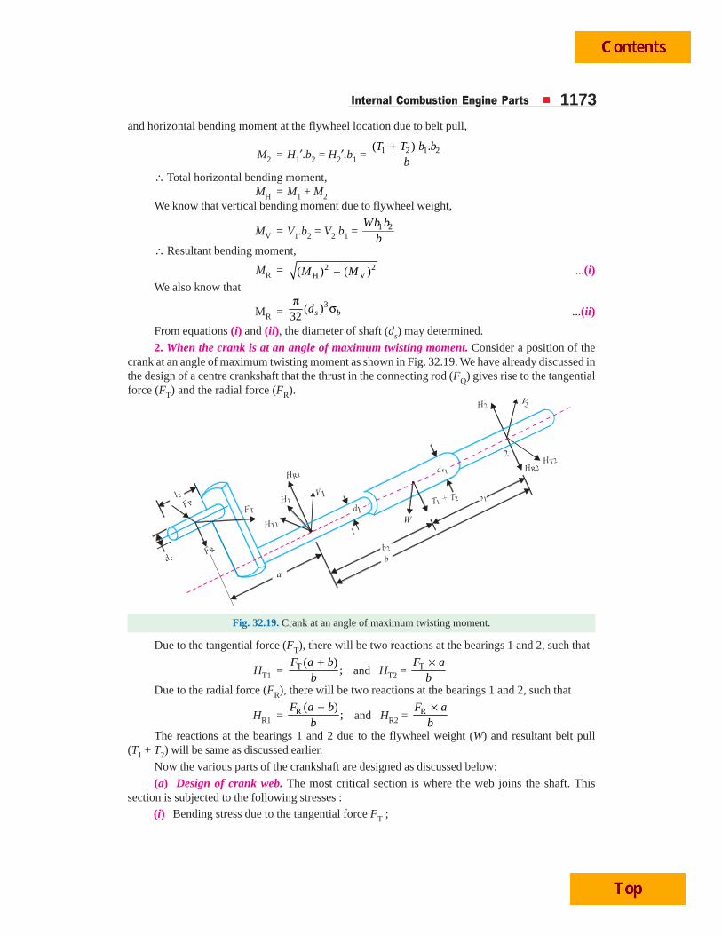
Internal Combustion Engine Parts 1173and horizontal bending moment at the flywheel location due to belt pull,
M2 = H1′.b2 = H2′.b1 = +1 2 1 2( ) .T T b b
b∴ Total horizontal bending moment,
MH = M1 + M2We know that vertical bending moment due to flywheel weight,
MV = V1.b2 = V2.b1 = 1 2Wb bb
∴ Resultant bending moment,
MR = 2 2H V( ) ( )M M+ ...(i)
We also know that
MR =3( )
32 s bdπ σ ...(ii)
From equations (i) and (ii), the diameter of shaft (ds) may determined.
2. When the crank is at an angle of maximum twisting moment. Consider a position of thecrank at an angle of maximum twisting moment as shown in Fig. 32.19. We have already discussed inthe design of a centre crankshaft that the thrust in the connecting rod (FQ) gives rise to the tangentialforce (FT) and the radial force (FR).
Fig. 32.19. Crank at an angle of maximum twisting moment.
Due to the tangential force (FT), there will be two reactions at the bearings 1 and 2, such that
HT1 = T ( );
F a bb
+ and HT2 = TF a
b×
Due to the radial force (FR), there will be two reactions at the bearings 1 and 2, such that
HR1 = R ( );
F a bb
+ and HR2 = RF a
b×
The reactions at the bearings 1 and 2 due to the flywheel weight (W) and resultant belt pull(T1 + T2) will be same as discussed earlier.
Now the various parts of the crankshaft are designed as discussed below:
(a) Design of crank web. The most critical section is where the web joins the shaft. Thissection is subjected to the following stresses :
(i) Bending stress due to the tangential force FT ;
1174 A Textbook of Machine Design
(ii) Bending stress due to the radial force FR ;(iii) Direct compressive stress due to the radial force FR ; and(iv) Shear stress due to the twisting moment of FT.
We know that bending moment due to the tangential force,
MbT = 1T 2
dF r
⎛ ⎞−⎜ ⎟⎝ ⎠
where d1 = Diameter of the bearing 1.
∴ Bending stress due to the tangential force,
σbT = =T T2
6Z .b bM M
t w...(Q Z = 21
·6
t w× ) ...(i)
We know that bending moment due to the radial force,MbR = FR (0.75 lc + 0.5 t)
∴ Bending stress due to the radial force,
σbR = R R2
6
.b bM M
Z w t= ...(Here Z = 21
·6
w t× ) ...(ii)
We know that direct compressive stress,
σd =R
.Fw t ...(iii)
∴ Total compressive stress,
σc = σbT + σbR + σd ...(iv)
We know that twisting moment due to the tangential force,
T = FT (0.75 lc + 0.5 t)
∴ Shear stress, τ = =2
P
4.5
.
T TZ w t
where ZP = Polar section modulus = 2.
4.5w t
Diesel, petrol and steam engines have crank shaft
Q
Internal Combustion Engine Parts 1175Now the total or maximum stress is given by
σmax = 2 21( ) 4
2 2c
cσ
+ σ + τ ...(v)
This total maximum stress should be less than the maximum allowable stress.(b) Design of shaft at the junction of crank
Let ds1 = Diameter of the shaft at the junction of the crank.We know that bending moment at the junction of the crank,
M = FQ (0.75lc + t)and twisting moment on the shaft
T = FT × r∴ Equivalent twisting moment,
Te = 2 2M T+ ...(i)
We also know that equivalent twisting moment,
Te = 31( )
16 sdπ τ ...(ii)
From equations (i) and (ii), the diameter of the shaft at the junction of the crank (ds1) may bedetermined.(c) Design of shaft under the flywheel
Let ds = Diameter of shaft under the flywheel.The resultant bending moment (MR) acting on the shaft is obtained in the similar way as
discussed for dead centre position.We know that horizontal bending moment acting on the shaft due to piston gas load,
M1 = ⎡ ⎤+ − +⎢ ⎥⎣ ⎦2 2
P 2 R1 T1 2( ) ( ) ( )F a b H H b
and horizontal bending moment at the flywheel location due to belt pull,
M2 = 1 2 1 21 2 2 1
( ) .. .
T T b bH b H b
b+
′ = ′ =∴ Total horizontal bending moment,
MH = M1 + M2Vertical bending moment due to the flywheel weight,
MV = V1· b2 = V2 · b1 = 1 2W b bb
∴ Resultant bending moment,
MR = 2 2H V( ) ( )M M+
We know that twisting moment on the shaft,T = FT × r
∴ Equivalent twisting moment,
Te = 2 2R( )M T+ ...(i)
We also know that equivalent twisting moment,
Te = 3( )16 sdπ τ ...(ii)
From equations (i) and (ii), the diameter of shaft under the flywheel (ds) may be determined.
Example 32.4. Design a plain carbon steel centre crankshaft for a single acting four strokesingle cylinder engine for the following data:
Q
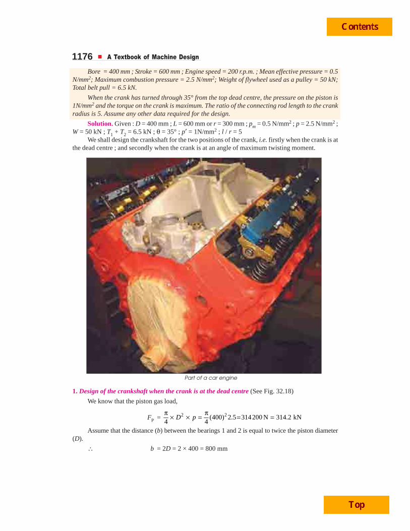
1176 A Textbook of Machine Design
Bore = 400 mm ; Stroke = 600 mm ; Engine speed = 200 r.p.m. ; Mean effective pressure = 0.5N/mm2; Maximum combustion pressure = 2.5 N/mm2; Weight of flywheel used as a pulley = 50 kN;Total belt pull = 6.5 kN.
When the crank has turned through 35° from the top dead centre, the pressure on the piston is1N/mm2 and the torque on the crank is maximum. The ratio of the connecting rod length to the crankradius is 5. Assume any other data required for the design.
Solution. Given : D = 400 mm ; L = 600 mm or r = 300 mm ; pm = 0.5 N/mm2 ; p = 2.5 N/mm2 ;W = 50 kN ; T1 + T2 = 6.5 kN ; θ = 35° ; p′ = 1N/mm2 ; l / r = 5
We shall design the crankshaft for the two positions of the crank, i.e. firstly when the crank is atthe dead centre ; and secondly when the crank is at an angle of maximum twisting moment.
1. Design of the crankshaft when the crank is at the dead centre (See Fig. 32.18)
We know that the piston gas load,
FP = 2 2(400) 2.5 314200 N 314.2 kN4 4
D pπ π× × = = =
Assume that the distance (b) between the bearings 1 and 2 is equal to twice the piston diameter(D).
∴ b = 2D = 2 × 400 = 800 mm
Part of a car engine
Internal Combustion Engine Parts 1177
and b1 = b2 = 800
400 mm2 2b = =
We know that due to the piston gas load, there will be two horizontal reactions H1 and H2 atbearings 1 and 2 respectively, such that
H1 = P 1 314.2 400157.1 kN
800F b
b× ×
= =
and H2 = P 2 314.2 400157.1 kN
800F b
b× ×= =
Assume that the length of the main bearings to be equal, i.e., c1 = c2 = c / 2. We know that dueto the weight of the flywheel acting downwards, there will be two vertical reactions V2 and V3 atbearings 2 and 3 respectively, such that
V2 = 1 / 2 502 2
W c W c Wc c× ×= = = = 25 kN
and V3 = 2 / 2 502 2
W c W c Wc c× ×= = = = 25 kN
Due to the resultant belt tension (T1 + T2) acting horizontally, there will be two horizontalreactions H2′ and H3′ respectively, such that
H2′ = 1 2 1 1 2 1 2( ) ( ) / 2 6.53.25kN
2 2T T c T T c T T
c c+ + +
= = = =
and H3′ = 1 2 2 1 2 1 2( ) ( ) / 2 6.53.25kN
2 2T T c T T c T T
c c+ + +
= = = =
Now the various parts of the crankshaft are designed as discussed below:(a) Design of crankpin
Let dc = Diameter of the crankpin in mm ;lc = Length of the crankpin in mm ; and
σb = Allowable bending stress for the crankpin. It may be assumed as75 MPa or N/mm2.
We know that the bending moment at the centre of the crankpin,MC = H1 · b2 = 157.1 × 400 = 62 840 kN-mm ...(i)
We also know that
MC = 3 3 3( ) ( ) 75 7.364( )32 32c b c cd d dπ πσ = = N-mm
= 7.364 × 10⁻³ (dc)3 kN-mm ...(ii)
Equating equations (i) and (ii), we have(dc)
3 = 62 840 / 7.364 × 10–3 = 8.53 × 10⁶
or dc = 204.35 say 205 mm Ans.We know that length of the crankpin,
lc = 3
P 314.2 10153.3
· 205 10c b
Fd p
×= =
× say 155 mm Ans.
...(Taking pb = 10 N/mm2)
(b) Design of left hand crank webWe know that thickness of the crank web,
t = 0.65 dc + 6.35 mm
= 0.65 × 205 + 6.35 = 139.6 say 140 mm Ans.
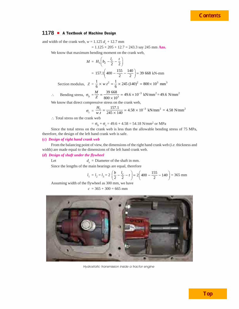
1178 A Textbook of Machine Design
and width of the crank web, w = 1.125 dc + 12.7 mm
= 1.125 × 205 + 12.7 = 243.3 say 245 mm Ans.We know that maximum bending moment on the crank web,
M = 1 2 2 2cl t
H b⎛ ⎞− −⎜ ⎟⎝ ⎠
=155 140
157.1 400 39 6682 2
⎛ ⎞− − =⎜ ⎟⎝ ⎠
kN-mm
Section modulus, Z = 2 2 3 31 1. 245 (140) 800 10 mm
6 6w t× = × = ×
∴ Bending stress, σb = 3 2 23
39 66849.6 10 kN/mm = 49.6 N/mm
800 10
MZ
−= = ××
We know that direct compressive stress on the crank web,
σc =3 2 21 157.1
4.58 10 kN/mm = 4.58 N/mm. 245 140
Hw t
−= = ××
∴ Total stress on the crank web
= σb + σc = 49.6 + 4.58 = 54.18 N/mm2 or MPa
Since the total stress on the crank web is less than the allowable bending stress of 75 MPa,therefore, the design of the left hand crank web is safe.
(c) Design of right hand crank webFrom the balancing point of view, the dimensions of the right hand crank web (i.e. thickness and
width) are made equal to the dimensions of the left hand crank web.
(d) Design of shaft under the flywheelLet ds = Diameter of the shaft in mm.
Since the lengths of the main bearings are equal, therefore
l1 = l2 = l3 = 2 155
2 400 1402 2 2
clbt
⎛ ⎞ ⎛ ⎞− − = − −⎜ ⎟⎜ ⎟ ⎝ ⎠⎝ ⎠ = 365 mm
Assuming width of the flywheel as 300 mm, we have
c = 365 + 300 = 665 mm
Hydrostatic transmission inside a tractor engine
Internal Combustion Engine Parts 1179Allowing space for gearing and clearance, let us take c = 800 mm.
∴ c1 = c2 = 800
4002 2c = = mm
We know that bending moment due to the weight of flywheel,
MW = V3 · c1 = 25 × 400 = 10 000 kN-mm = 10 × 106 N-mm
and bending moment due to the belt pull,
MT = H3′ · c1 = 3.25 × 400 = 1300 kN-mm = 1.3 × 10⁶ N-mm
∴ Resultant bending moment on the shaft,
MS = 2 2 6 2 6 2W T( ) ( ) (10 10 ) (1.3 10 )M M+ = × + ×
= 10.08 × 10⁶ N-mm
We also know that bending moment on the shaft (MS),
10.08 × 106 = 3 3 3( ) ( ) 42 4.12 ( )32 32s b s sd d dπ πσ = =
∴ (ds)3 = 10.08 × 10⁶ / 4.12 = 2.45 × 10⁶ or ds = 134.7 say 135 mm Ans.
2. Design of the crankshaft when the crank is at an angle of maximum twisting momentWe know that piston gas load,
FP = 2 2(400) 1 125 6804 4
D pπ π
× × ′ = = N = 125.68 kN
In order to find the thrust in the connecting rod (FQ), we should first find out the angle ofinclination of the connecting rod with the line of stroke (i.e. angle φ). We know that
sin φ =sin sin 35
0.1147/ 5l r
θ °= =
∴ φ = sin–1 (0.1147) = 6.58°
We know that thrust in the connecting rod,
FQ =P 125.68 125.68
cos cos 6.58º 0.9934F = =
φ = 126.5 kN
Tangential force acting on the crankshaft,
FT = FQ sin (θ + φ) = 126.5 sin (35° + 6.58°) = 84 kN
and radial force, FR = FQ cos (θ + φ) = 126.5 cos (35° + 6.58°) = 94.6 kN
Due to the tangential force (FT), there will be two reactions at bearings 1 and 2, such that
HT1 = T 1 84 400800
F bb× ×
= = 42 kN
and HT2 = T 2 84 400800
F bb× ×
= = 42 kN
Due to the radial force (FR), there will be two reactions at bearings 1 and 2, such that
HR1 = R 1 94.6 400800
F bb× ×
= = 47.3 kN
HR2 = R 2 94.6 400800
F bb× ×= = 47.3 kN
Now the various parts of the crankshaft are designed as discussed below:
(a) Design of crankpinLet dc = Diameter of crankpin in mm.
1180 A Textbook of Machine Design
We know that the bending moment at the centre of the crankpin,
MC = HR1 × b2 = 47.3 × 400 = 18 920 kN-mm
and twisting moment on the crankpin,
TC = HT1 × r = 42 × 300 = 12 600 kN-mm
∴ Equivalent twisting moment on the crankpin,
Te = 2 2 2 2C C( ) ( ) (18 920) (12 600)M T+ = +
= 22 740 kN-mm = 22.74 × 10⁶ N-mm
We know that equivalent twisting moment (Te),
22.74 × 106 = 3 3 3( ) ( ) 35 6.873 ( )16 16c c cd d dπ πτ = =
...(Taking τ = 35 MPa or N/mm2)
∴ (dc)3 = 22.74 × 10⁶ / 6.873 = 3.3 × 10⁶ or dc = 149 mm
Since this value of crankpin diameter (i.e. dc = 149 mm) is less than the already calculated valueof dc = 205 mm, therefore, we shall take dc = 205 mm. Ans.(b) Design of shaft under the flywheel
Let ds = Diameter of the shaft in mm.
The resulting bending moment on the shaft will be same as calculated eariler, i.e.
MS = 10.08 × 10⁶ N-mm
and twisting moment on the shaft,
TS = FT × r = 84 × 300 = 25 200 kN-mm = 25.2 × 10⁶ N-mm
∴ Equivalent twisting moment on shaft,
Te = 2 2S S( ) ( )M T+
= 6 2 6 2 6(10.08 10 ) (25.2 10 ) 27.14 10× + × = × N-mm
We know that equivalent twisting moment (Te),
27.14 × 106 = 3 3( ) (135) 483 15616 16sdπ πτ = τ = τ
∴ τ = 27.14 × 10⁶ / 483 156 = 56.17 N/mm2
From above, we see that by taking the already calculated value of ds = 135 mm, the inducedshear stress is more than the allowable shear stress of 31 to 42 MPa. Hence, the value of ds iscalculated by taking τ = 35 MPa or N/mm2 in the above equation, i.e.
27.14 × 106 = 3 3( ) 35 6.873 ( )16 s sd dπ =
∴ (ds)3 = 27.14 × 10⁶ / 6.873 = 3.95 × 10⁶ or ds = 158 say 160 mm Ans.
(c) Design of shaft at the juncture of right hand crank arm
Let ds1 = Diameter of the shaft at the juncture of the right hand crank arm.
We know that the resultant force at the bearing 1,
R1 = 2 2 2 2T1 R1( ) ( ) (42) (47.3) 63.3H H+ = + = kN
∴ Bending moment at the juncture of the right hand crank arm,
MS1 = R1 2 Q2 2 2 2c cl lt t
b F⎛ ⎞ ⎛ ⎞+ + − +⎜ ⎟ ⎜ ⎟⎝ ⎠ ⎝ ⎠
Internal Combustion Engine Parts 1181
= 63.3 155 140 155 140
400 126.52 2 2 2
⎛ ⎞ ⎛ ⎞+ + − +⎜ ⎟ ⎜ ⎟⎝ ⎠ ⎝ ⎠
= 34.7 × 10³ – 18.7 × 103 = 16 × 103 kN-mm = 16 × 106 N-mm
and twisting moment at the juncture of the right hand crank arm,
TS1 = FT × r = 84 × 300 = 25 200 kN-mm = 25.2 × 10⁶ N-mm
∴ Equivalent twisting moment at the juncture of the right hand crank arm,
Te = 2 2S1 S1( ) ( )M T+
= 6 2 6 2 6(16 10 ) (25.2 10 ) 29.85 10× + × = × N-mm
We know that equivalent twisting moment (Te),
29.85 × 106 = 3 3 31 1 1( ) ( ) 42 8.25 ( )
16 16s s sd d dπ πτ = =
...(Taking τ = 42 MPa or N/mm2)
∴ (ds1)3 = 29.85 × 10⁶ / 8.25 = 3.62 × 10⁶ or ds1 = 153.5 say 155 mm Ans.
(d) Design of right hand crank web
Let σbR = Bending stress in the radial direction ; and
σbT = Bending stress in the tangential direction.
We also know that bending moment due to the radial component of FQ,
MR = HR2 1 2 2cl t
b⎛ ⎞− −⎜ ⎟⎝ ⎠
= 47.3 155 140
4002 2
⎛ ⎞− −⎜ ⎟⎝ ⎠
kN-mm
= 11.94 × 10³ kN-mm = 11.94 × 10⁶ N-mm ...(i)
We also know that bending moment,
MR = σbR × Z = σbR × 21.
6w t× ... 21
( . )6
Z w t= ×Q
11.94 × 106 = σbR × 2 3R
1245 (140) 800 10
6 b× = × σ
∴ σbR = 11.94 × 10⁶ / 800 × 103 = 14.9 N/mm2 or MPa
We know that bending moment due to the tangential component of FQ,
MT = 1T
15584 300
2 2sd
F r⎛ ⎞ ⎛ ⎞− = −⎜ ⎟⎜ ⎟ ⎝ ⎠⎝ ⎠
= 18 690 kN-mm
= 18.69 × 10⁶ N-mm
We also know that bending moment,
MT = σbT × Z = σbT × 21.
6t w× ... 21
( . )6
Z t w= ×Q
18.69 × 106 = σbT × 2 61140(245) 1.4 10
6× = × σbT
∴ σbT = 18.69 × 10⁶ / 1.4 × 106 = 13.35 N/mm2 or MPa
Direct compressive stress,
σb = 3R 94.6
1.38 102 · 2 245 140
Fw t
−= = ×× ×
kN/mm2 = 1.38 N/mm2
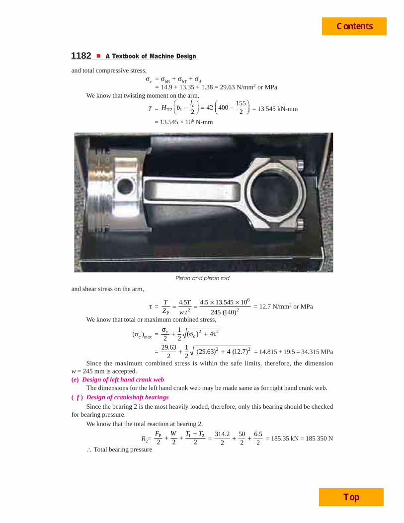
1182 A Textbook of Machine Design
and total compressive stress,σc = σbR + σbT + σd
= 14.9 + 13.35 + 1.38 = 29.63 N/mm2 or MPaWe know that twisting moment on the arm,
T = T2 1155
42 4002 2clH b
⎛ ⎞ ⎛ ⎞− = −⎜ ⎟⎜ ⎟ ⎝ ⎠⎝ ⎠ = 13 545 kN-mm
= 13.545 × 10⁶ N-mm
and shear stress on the arm,
τ =6
2 2P
4.5 4.5 13.545 10
. 245 (140)
T TZ w t
× ×= = = 12.7 N/mm2 or MPa
We know that total or maximum combined stress,
(σc )max = 2 21( ) 4
2 2c
cσ
+ σ + τ
= 2 229.63 1(29.63) 4 (12.7)
2 2+ + = 14.815 + 19.5 = 34.315 MPa
Since the maximum combined stress is within the safe limits, therefore, the dimensionw = 245 mm is accepted.(e) Design of left hand crank web
The dimensions for the left hand crank web may be made same as for right hand crank web.
( f ) Design of crankshaft bearingsSince the bearing 2 is the most heavily loaded, therefore, only this bearing should be checked
for bearing pressure.
We know that the total reaction at bearing 2,
R2= P 1 2
2 2 2F T TW +
+ + = 314.2 50 6.5
2 2 2+ + = 185.35 kN = 185 350 N
∴ Total bearing pressure
Piston and piston rod
Internal Combustion Engine Parts 1183
= 22
2 1
185 3503.276 N/mm
· 365 155s
Rl d
= =×
Since this bearing pressure is less than the safe limit of 5 to 8 N/mm2, therefore, the design is safe.
Example 32.5. Design a side or overhung crankshaft for a 250 mm × 300 mm gas engine. Theweight of the flywheel is 30 kN and the explosion pressure is 2.1 N/mm2. The gas pressure at themaximum torque is 0.9 N/mm2, when the crank angle is 35° from I. D. C. The connecting rod is 4.5times the crank radius.
Solution. Given : D = 250 mm ; L = 300 mm or r = L / 2 = 300 / 2 = 150 mm ; W = 30 kN= 30 × 103 N ; p = 2.1 N/mm2, p′ = 0.9 N/mm2 ; l = 4.5 r or l / r = 4.5
We shall design the crankshaft for thetwo positions of the crank, i.e. firstly whenthe crank is at the dead centre and secondlywhen the crank is at an angle of maximumtwisting moment.
1. Design of crankshaft when the crank isat the dead centre (See Fig. 32.18)
We know that piston gas load,
FP = 2
4D p
π× ×
2 3(250) 2.1 103 104π
= = × N
Now the various parts of the crankshaftare designed as discussed below:
(a) Design of crankpinLet dc = Diameter of the crankpin in mm, and
lc = Length of the crankpin = 0.8 dc ...(Assume)
Considering the crankpin in bearing, we have
FP = dc.lc.pb
103 × 103 = dc × 0.8 dc × 10 = 8 (dc)2 ...(Taking pb = 10 N/mm2)
∴ (dc)2 = 103 × 103 / 8 = 12 875 or dc = 113.4 say 115 mm
and lc = 0.8 dc = 0.8 × 115 = 92 mm
Let us now check the induced bending stress in the crankpin.
We know that bending moment at the crankpin,
M = 3 3P
3 3103 10 92 7107 10
4 4cF l× = × × × = × N-mm
and section modulus of the crankpin,
Z = 3 3 3 3( ) (115) 149 10 mm32 32cdπ π= = ×
∴ Bending stress induced
= 3
23
7107 1047.7 N/mm
149 10
MZ
×= =×
or MPa
Since the induced bending stress is within the permissible limits of 60 MPa, therefore, design ofcrankpin is safe.
Valve guides of an IC engine
1184 A Textbook of Machine Design
(b) Design of bearingsLet d1 = Diameter of the bearing 1.
Let us take thickness of the crank web,
t = 0.6 dc= 0.6 × 115 = 69 or 70 mm
and length of the bearing, l1 = 1.7 dc = 1.7 × 115 = 195.5 say 200 mmWe know that bending moment at the centre of the bearing 1,
M = FP (0.75lc + t + 0.5 l1)= 103 × 103 (0.75 × 92 + 70 + 0.5 × 200) = 24.6 × 10⁶ N-mm
We also know that bending moment (M),
24.6 × 106 = 3 3 31 1 1( ) ( ) 60 5.9 ( )
32 32bd d dπ πσ = =
...(Taking σb = 60 MPa or N/mm2)
∴ (d1)3 = 24.6 × 10⁶ /5.9 = 4.2 × 10⁶ or d1 = 161.3 mm say 162 mm Ans.
(c) Design of crank webLet w = Width of the crank web in mm.We know that bending moment on the crank web,
M = FP (0.75lc + 0.5 t)= 103 × 103 (0.75 × 92 + 0.5 × 70) = 10.7 × 10⁶ N-mm
and section modulus, Z = 2 2 31 1· (70) 817 mm
6 6w t w w× = × =
∴ Bending stress,6 310.7 10 13 10
817bMZ w w
× ×σ = = = N/mm2
and direct compressive stress,
σb = 3 3
P 103 10 1.47 10. 70
Fw t w w
× ×= =× N/mm2
We know that total stress on the crank web,
σT = σb + σd = 3 3 313 10 1.47 10 14.47 10
+w w w× × ×
= N/mm2
The total stress should not exceed the permissible limit of 60 MPa or N/mm2.
∴ 60 = 3 314.47 10 14.47 10
or60
× ×= =w
w241 say 245 mm Ans.
(d) Design of shaft under the flywheel.Let ds = Diameter of shaft under the flywheel.First of all, let us find the horizontal and vertical reactions at bearings 1 and 2. Assume that the
width of flywheel is 250 mm and l1 = l2 = 200 mm.Allowing for certain clearance, the distance
b = 1 22502 2l l
+ + + clearance
= 250 + 200 200
202 2
+ + = 470 mm
and a = 0.75 lc + t + 0.5 l1
= 0.75 × 92 + 70 + 0.5 × 200 = 239 mm
We know that the horizontal reactions H1 and H2 at bearings 1 and 2, due to the piston gas load(FP) are
Internal Combustion Engine Parts 1185
H1 = 3
3P ( ) 103 10 (239 470)155.4 10
470F a b
b+ × +
= = × N
and H2 = 3
3P 103 10 23952.4 10
470F a
b× × ×
= = × N
Assuming b1 = b2 = b / 2, the vertical reactions V1 and V2 at bearings 1 and 2 due to the weightof the flywheel are
V1 = 3
31· / 2 30 1015 10
2 2W b W b W
b b× ×
= = = = × N
and V2 = 3
32· / 2 30 1015 10
2 2W b W b W
b b× ×= = = = × N
Since there is no belt tension, therefore the horizontal reactions due to the belt tension areneglected.
We know that horizontal bending moment at the flywheel location due to piston gas load.M1 = FP (a + b2) – H1 · b2
= 103 × 103 3470 470239 155.4 10
2 2⎛ ⎞+ − × ×⎜ ⎟⎝ ⎠
... 2 2b
b⎛ ⎞=⎜ ⎟⎝ ⎠Q
= 48.8 × 10⁶ – 36.5 × 106 = 12.3 × 10⁶ N-mmSince there is no belt pull, therefore, there will be no horizontal bending moment due to the belt
pull, i.e. M2 = 0.∴ Total horizontal bending moment,
MH = M1 + M2 = M1 = 12.3 × 10⁶ N-mmWe know that vertical bending moment due to the flywheel weight,
MV = 1 2. .
2 2 4W b b W b b W b
b b× × ×= =× ×
= 3
630 10 4703.525 10
4× × = × N-mm
Inside view of a car engine
1186 A Textbook of Machine Design
∴ Resultant bending moment,
MR = 2 2 6 2 6 2H V( ) ( ) (12.3 10 ) (3.525 10 )M M+ = × + ×
= 12.8 × 10⁶ N-mm
We know that bending moment (MR),
12.8 × 106 = 3 3 3( ) ( ) 60 5.9( )32 32s b s sd d dπ πσ = =
∴ (ds)3 = 12.8 × 10⁶ / 5.9 = 2.17 × 10⁶ or ds = 129 mm
Actually ds should be more than d1. Therefore let us take
ds = 200 mm Ans.
2. Design of crankshaft when the crank is at an angtle of maximum twisting moment
We know that piston gas load,
FP = 2 2(250) 0.9 44 2004 4
D pπ π
× × ′ = = N
In order to find the thrust in the connecting rod (FQ), we should first find out the angle ofinclination of the connecting rod with the line of storke (i.e. angle φ). We know that
sin φ = sin sin 35
0.1275/ 4.5l r
θ °= =
∴ φ = sin–1 (0.1275) = 7.32°
We know that thrust in the connecting rod,
FQ = P 44 200 44 20044 565
cos cos 7.32º 0.9918F
= = =φ
N
Tangential force acting on the crankshaft,
FT = FQ sin (θ + φ) = 44 565 sin (35º + 7.32º) = 30 × 103 N
and radial force, FR = FQ cos (θ + φ) = 44 565 cos (35º + 7.32º) = 33 × 103 N
Due to the tangential force (FT), there will be two reactions at the bearings 1 and 2, such that
HT1 = 3
3T ( ) 30 10 (239 470)45 10
470F a b
b+ × +
= = × N
and HT2 = 3
3T 30 10 23915.3 10
470F a
b× × ×
= = × N
Due to the radial force (FR), there will be two reactions at the bearings 1 and 2, such that
HR1 = 3
3R ( ) 33 10 (239 470)49.8 10
470F a b
b+ × × +
= = × N
and HR2 = 3
3R 33 10 23916.8 10
470F a
b× × ×
= = × N
Now the various parts of the crankshaft are designed as discussed below:
(a) Design of crank web
We know that bending moment due to the tangential force,
MbT = 3 61T
18030 10 150 1.8 10
2 2d
F r⎛ ⎞ ⎛ ⎞− = × − = ×⎜ ⎟⎜ ⎟ ⎝ ⎠⎝ ⎠
N-mm
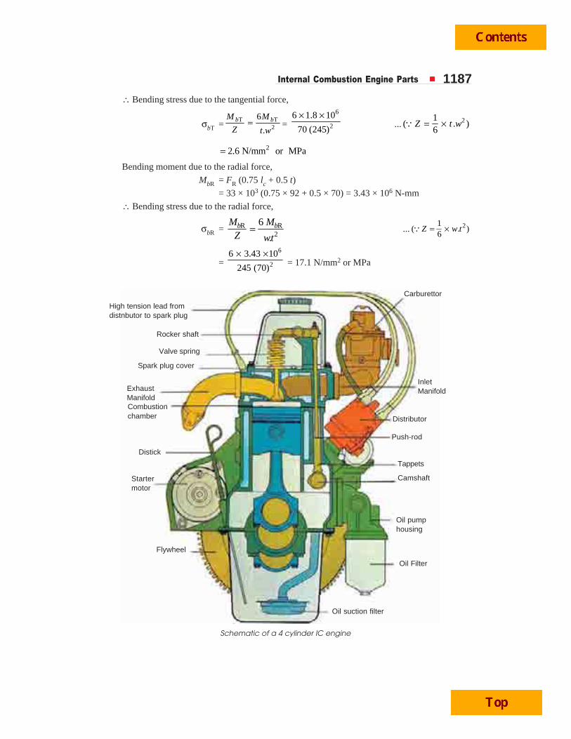
Internal Combustion Engine Parts 1187∴ Bending stress due to the tangential force,
σbT =T T
2
6
.b bM M
Z t w= =
6
2
6 1.8 10
70 (245)
× ×... 21
( . )6
Z t w= ×Q
22.6 N/mm or MPa=
Bending moment due to the radial force,
MbR = FR (0.75 lc + 0.5 t)
= 33 × 103 (0.75 × 92 + 0.5 × 70) = 3.43 × 10⁶ N-mm
∴ Bending stress due to the radial force,
σbR = R R2
6
.b bM M
Z wt= ... 21
( . )6
Z w t= ×Q
=
6
2
6 3.43 10
245 (70)
× × = 17.1 N/mm2 or MPa
Schematic of a 4 cylinder IC engine
High tension lead fromdistnbutor to spark plug
Rocker shaft
Valve spring
Spark plug cover
ExhaustManifoldCombustionchamber
Distick
Startermotor
Flywheel
Oil suction filter
Oil Filter
Oil pumphousing
Camshaft
Tappets
Push-rod
Distributor
InletManifold
Carburettor
1188 A Textbook of Machine Design
We know that direct compressive stress,
σd = 3
R 33 10· 245 70
Fw t
×=× = 1.9 N/mm2 or MPa
∴ Total compressive stress,
σc = σbT + σbR + σd = 2.6 + 17.1 + 1.9 = 21.6 MPa
We know that twisting moment due to the tangential force,
T = FT (0.75 lc + 0.5 t)
= 30 × 103 (0.75 × 92 + 0.5 × 70) = 3.12 × 10⁶ N-mm
∴ Shear stress, τ = 2P
4.5
·
T TZ w t
= 6
2
4.5 3.12 10
245 (70)
× ×= ...2
P·
4.5w t
Z⎡ ⎤
=⎢ ⎥⎢ ⎥⎣ ⎦Q
= 11.7 N/mm2 or MPa
We know that total or maximum stress,
σmax = 2 21( ) 4
2 2c
cσ
+ σ + τ = 2 221.6 1(21.6) 4(11.7)
2 2+ +
= 10.8 + 15.9 = 26.7 MPa
Since this stress is less than the permissible value of 60 MPa, therefore, the design is safe.
(b) Design of shaft at the junction of crank
Let ds1 = Diameter of shaft at the junction of crank.
We know that bending moment at the junction of crank,
M = FQ (0.75lc + t) = 44 565 (0.75 × 92 + 70) = 6.2 × 10⁶ N-mm
and twisting moment, T = FT × r = 30 × 103 × 150 = 4.5 × 10⁶ N-mm
∴ Equivalent twisting moment,
Te = 2 2 6 2 6 2(6.2 10 ) (4.5 10 )M T+ = × + × = 7.66 × 10⁶ N-mm
We also know that equivalent twisting moment (Te),
7.66 × 106 = 3 3 61( ) (180) 1.14 10
16 16sdπ πτ = τ = × τ ...(Taking ds1 = d1)
∴ τ = 7.66 × 10⁶ / 1.14 × 106 = 6.72 N/mm2 or MPa
Since the induced shear stress is less than the permissible limit of 30 to 40 MPa, therefore, thedesign is safe.
(c) Design of shaft under the flywheel
Let ds = Diameter of shaft under the flywheel.
We know that horizontal bending moment acting on the shaft due to piston gas load,
MH = 2 2
P 2 R1 T1 2( ) ( ) ( )F a b H H b⎡ ⎤+ − +⎢ ⎥⎣ ⎦
= 44 200 3 2 3 2470 470
239 (49.8 10 ) (45 10 )2 2
⎛ ⎞ ⎡ ⎤+ − × + ×⎜ ⎟ ⎢ ⎥⎣ ⎦⎝ ⎠= 20.95 × 10⁶ – 15.77 × 106 = 5.18 × 10⁶ N-mm
and bending moment due to the flywheel weight
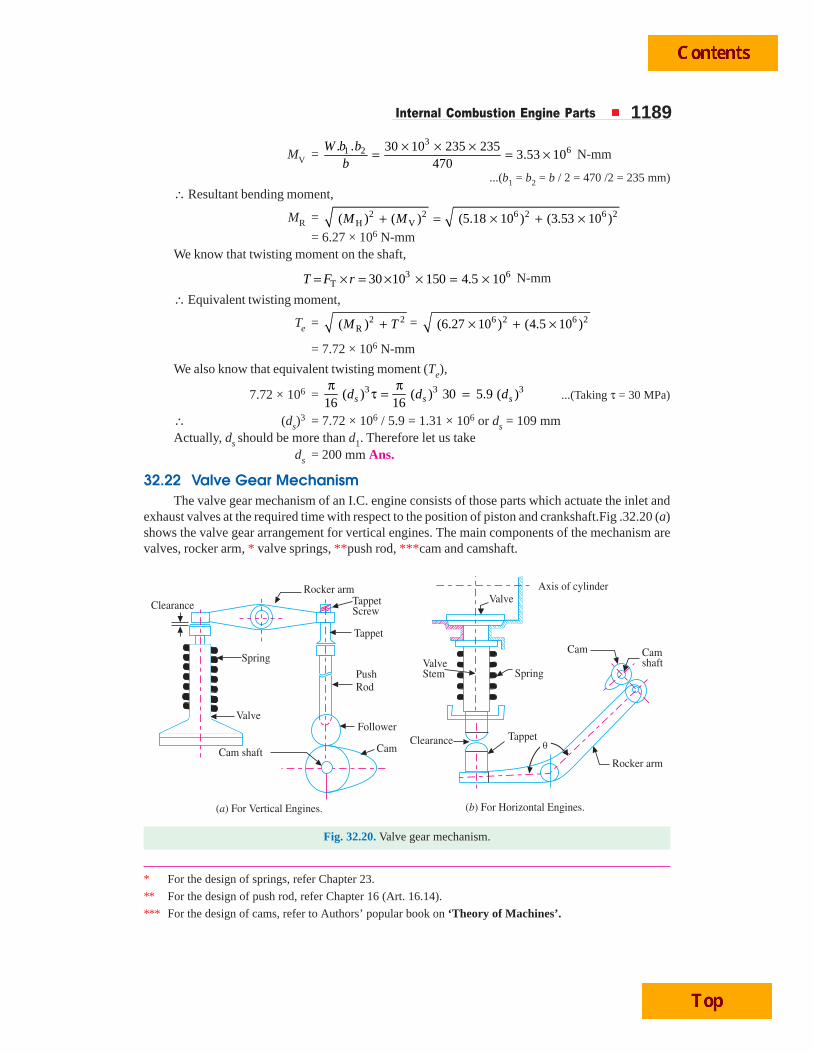
Internal Combustion Engine Parts 1189
MV = 3
61 2. . 30 10 235 2353.53 10
470W b b
b× × ×= = × N-mm
...(b1 = b2 = b / 2 = 470 /2 = 235 mm)
∴ Resultant bending moment,
MR = 2 2 6 2 6 2H V( ) ( ) (5.18 10 ) (3.53 10 )M M+ = × + ×
= 6.27 × 10⁶ N-mmWe know that twisting moment on the shaft,
3 6T 30 10 150 4.5 10T F r= × = × × = × N-mm
∴ Equivalent twisting moment,
Te = 2 2R( )M T+ = 6 2 6 2(6.27 10 ) (4.5 10 )× + ×
= 7.72 × 10⁶ N-mm
We also know that equivalent twisting moment (Te),
7.72 × 106 = 3 3 3( ) ( ) 30 5.9 ( )16 16s s sd d dπ π
τ = = ...(Taking τ = 30 MPa)
∴ (ds)3 = 7.72 × 10⁶ / 5.9 = 1.31 × 10⁶ or ds = 109 mm
Actually, ds should be more than d1. Therefore let us takeds = 200 mm Ans.
32.22 Valve Gear MechanismThe valve gear mechanism of an I.C. engine consists of those parts which actuate the inlet and
exhaust valves at the required time with respect to the position of piston and crankshaft.Fig .32.20 (a)shows the valve gear arrangement for vertical engines. The main components of the mechanism arevalves, rocker arm, * valve springs, **push rod, ***cam and camshaft.
Fig. 32.20. Valve gear mechanism.
* For the design of springs, refer Chapter 23.
** For the design of push rod, refer Chapter 16 (Art. 16.14).
*** For the design of cams, refer to Authors’ popular book on ‘Theory of Machines’.
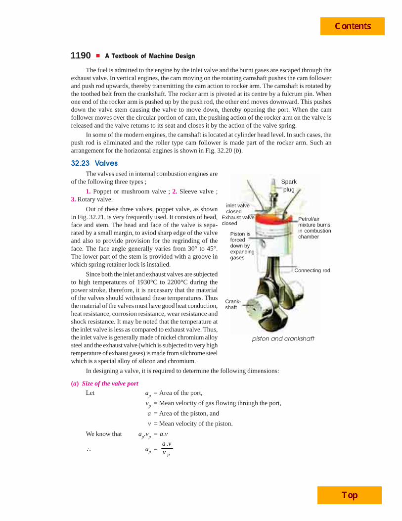
1190 A Textbook of Machine Design
The fuel is admitted to the engine by the inlet valve and the burnt gases are escaped through theexhaust valve. In vertical engines, the cam moving on the rotating camshaft pushes the cam followerand push rod upwards, thereby transmitting the cam action to rocker arm. The camshaft is rotated bythe toothed belt from the crankshaft. The rocker arm is pivoted at its centre by a fulcrum pin. Whenone end of the rocker arm is pushed up by the push rod, the other end moves downward. This pushesdown the valve stem causing the valve to move down, thereby opening the port. When the camfollower moves over the circular portion of cam, the pushing action of the rocker arm on the valve isreleased and the valve returns to its seat and closes it by the action of the valve spring.
In some of the modern engines, the camshaft is located at cylinder head level. In such cases, thepush rod is eliminated and the roller type cam follower is made part of the rocker arm. Such anarrangement for the horizontal engines is shown in Fig. 32.20 (b).
32.23 ValvesThe valves used in internal combustion engines are
of the following three types ;
1. Poppet or mushroom valve ; 2. Sleeve valve ;3. Rotary valve.
Out of these three valves, poppet valve, as shownin Fig. 32.21, is very frequently used. It consists of head,face and stem. The head and face of the valve is sepa-rated by a small margin, to aviod sharp edge of the valveand also to provide provision for the regrinding of theface. The face angle generally varies from 30° to 45°.The lower part of the stem is provided with a groove inwhich spring retainer lock is installed.
Since both the inlet and exhaust valves are subjectedto high temperatures of 1930°C to 2200°C during thepower stroke, therefore, it is necessary that the materialof the valves should withstand these temperatures. Thusthe material of the valves must have good heat conduction,heat resistance, corrosion resistance, wear resistance andshock resistance. It may be noted that the temperature atthe inlet valve is less as compared to exhaust valve. Thus,the inlet valve is generally made of nickel chromium alloysteel and the exhaust valve (which is subjected to very hightemperature of exhaust gases) is made from silchrome steelwhich is a special alloy of silicon and chromium.
In designing a valve, it is required to determine the following dimensions:
(a) Size of the valve portLet ap = Area of the port,
vp = Mean velocity of gas flowing through the port,
a = Area of the piston, and
v = Mean velocity of the piston.
We know that ap.vp = a.v
∴ ap =.
p
a vv
piston and crankshaft
Sparkplug
Petrol/airmixture burnsin combustionchamber
Connecting rod
Crank-shaft
Piston isforceddown byexpandinggases
inlet valveclosed
Exhaust valveclosed
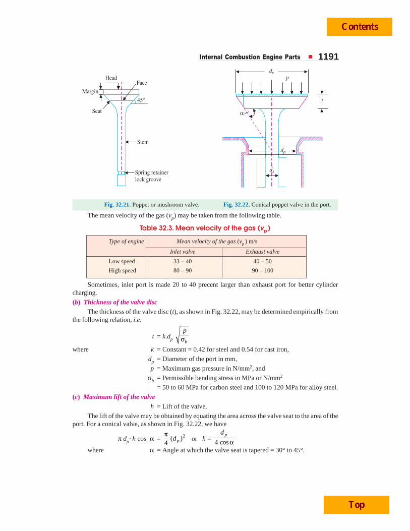
Internal Combustion Engine Parts 1191
Fig. 32.21. Poppet or mushroom valve. Fig. 32.22. Conical poppet valve in the port.
The mean velocity of the gas (vp) may be taken from the following table.
Table 32.3. Mean velocity of the gas (vp )
Type of engine Mean velocity of the gas (vp ) m/s
Inlet valve Exhaust valve
Low speed 33 – 40 40 – 50
High speed 80 – 90 90 – 100
Sometimes, inlet port is made 20 to 40 precent larger than exhaust port for better cylindercharging.
(b) Thickness of the valve discThe thickness of the valve disc (t), as shown in Fig. 32.22, may be determined empirically from
the following relation, i.e.
t = k.dp b
pσ
where k = Constant = 0.42 for steel and 0.54 for cast iron,
dp = Diameter of the port in mm,
p = Maximum gas pressure in N/mm2, and
σb = Permissible bending stress in MPa or N/mm2
= 50 to 60 MPa for carbon steel and 100 to 120 MPa for alloy steel.
(c) Maximum lift of the valveh = Lift of the valve.
The lift of the valve may be obtained by equating the area across the valve seat to the area of theport. For a conical valve, as shown in Fig. 32.22, we have
π dp· h cos α = 2( )4 pdπ
or h = 4 cospd
αwhere α = Angle at which the valve seat is tapered = 30° to 45°.
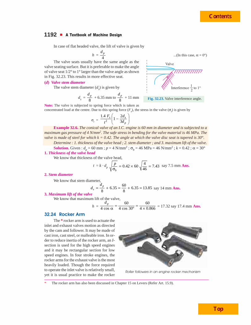
1192 A Textbook of Machine Design
In case of flat headed valve, the lift of valve is given by
h = 4pd
...(In this case, α = 0°)
The valve seats usually have the same angle as thevalve seating surface. But it is preferable to make the angleof valve seat 1/2° to 1° larger than the valve angle as shownin Fig. 32.23. This results in more effective seat.
(d) Valve stem diameterThe valve stem diameter (ds) is given by
ds = 8pd
+ 6.35 mm to 8pd
+ 11 mm
Note: The valve is subjected to spring force which is taken asconcentrated load at the centre. Due to this spring force (Fs), the stress in the valve (σt) is given by
σt = 2
1.4 21
3s s
p
F ddt
⎛ ⎞−⎜ ⎟
⎝ ⎠Example 32.6. The conical valve of an I.C. engine is 60 mm in diameter and is subjected to a
maximum gas pressure of 4 N/mm2. The safe stress in bending for the valve material is 46 MPa. Thevalve is made of steel for which k = 0.42. The angle at which the valve disc seat is tapered is 30°.
Determine : 1. thickness of the valve head ; 2. stem diameter ; and 3. maximum lift of the valve.Solution. Given : dp = 60 mm ; p = 4 N/mm2 ; σb = 46 MPa = 46 N/mm2 ; k = 0.42 ; α = 30°
1. Thickness of the valve headWe know that thickness of the valve head,
t = k · dp 4
0.42 60 7.4346b
p = × =σ
say 7.5 mm Ans.
2. Stem diameter
We know that stem diameter,60
6.35 6.35 13.858 8p
s
dd = + = + = say 14 mm Ans.
3. Maximum lift of the valveWe know that maximum lift of the valve,
h = 60 60
4 cos 4 cos 30º 4 0.866pd
= =α × = 17.32 say 17.4 mm Ans.
32.24 Rocker ArmThe * rocker arm is used to actuate the
inlet and exhaust valves motion as directedby the cam and follower. It may be made ofcast iron, cast steel, or malleable iron. In or-der to reduce inertia of the rocker arm, an I-section is used for the high speed enginesand it may be rectangular section for lowspeed engines. In four stroke engines, therocker arms for the exhaust valve is the mostheavily loaded. Though the force requiredto operate the inlet valve is relatively small,yet it is usual practice to make the rocker
* The rocker arm has also been discussed in Chapter 15 on Levers (Refer Art. 15.9).
Roller followers in an engine rocker mechanism
Fig. 32.23. Valve interference angle.
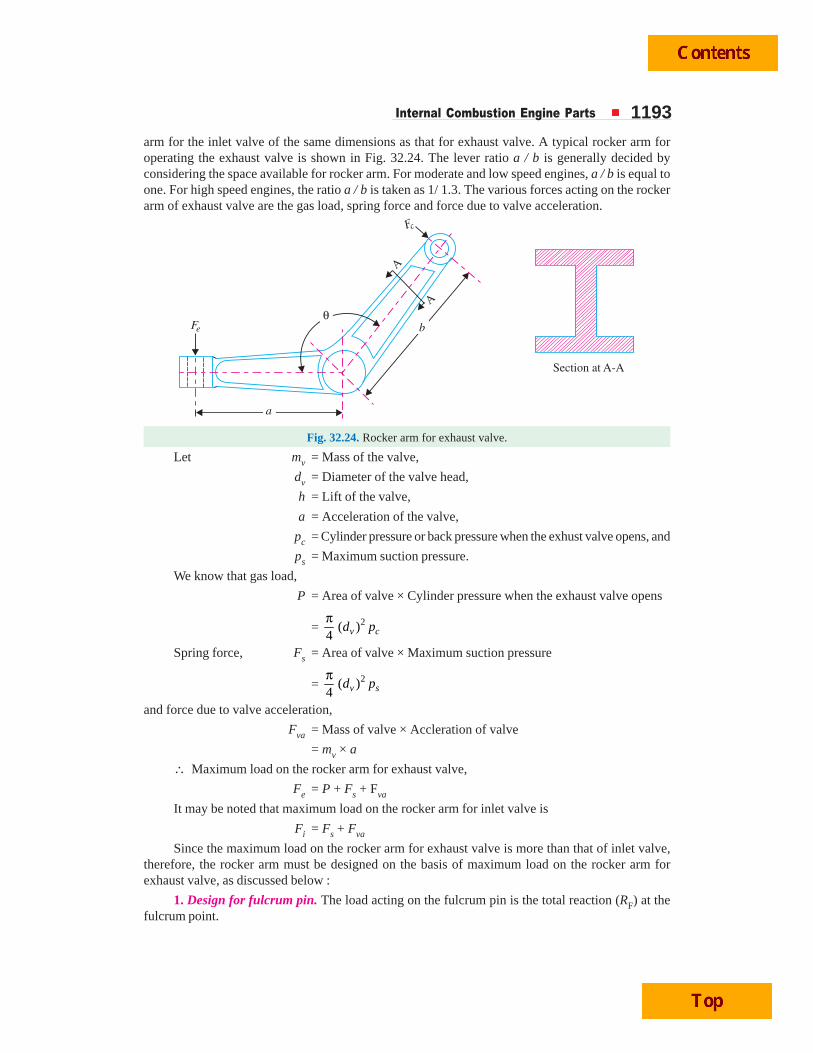
Internal Combustion Engine Parts 1193arm for the inlet valve of the same dimensions as that for exhaust valve. A typical rocker arm foroperating the exhaust valve is shown in Fig. 32.24. The lever ratio a / b is generally decided byconsidering the space available for rocker arm. For moderate and low speed engines, a / b is equal toone. For high speed engines, the ratio a / b is taken as 1/ 1.3. The various forces acting on the rockerarm of exhaust valve are the gas load, spring force and force due to valve acceleration.
Fig. 32.24. Rocker arm for exhaust valve.
Let mv = Mass of the valve,
dv = Diameter of the valve head,
h = Lift of the valve,
a = Acceleration of the valve,
pc = Cylinder pressure or back pressure when the exhust valve opens, and
ps = Maximum suction pressure.
We know that gas load,
P = Area of valve × Cylinder pressure when the exhaust valve opens
= 2( )4 v cd pπ
Spring force, Fs = Area of valve × Maximum suction pressure
= 2( )4 v sd pπ
and force due to valve acceleration,
Fva = Mass of valve × Accleration of valve
= mv × a
∴ Maximum load on the rocker arm for exhaust valve,
Fe = P + Fs + Fva
It may be noted that maximum load on the rocker arm for inlet valve is
Fi = Fs + Fva
Since the maximum load on the rocker arm for exhaust valve is more than that of inlet valve,therefore, the rocker arm must be designed on the basis of maximum load on the rocker arm forexhaust valve, as discussed below :
1. Design for fulcrum pin. The load acting on the fulcrum pin is the total reaction (RF) at thefulcrum point.
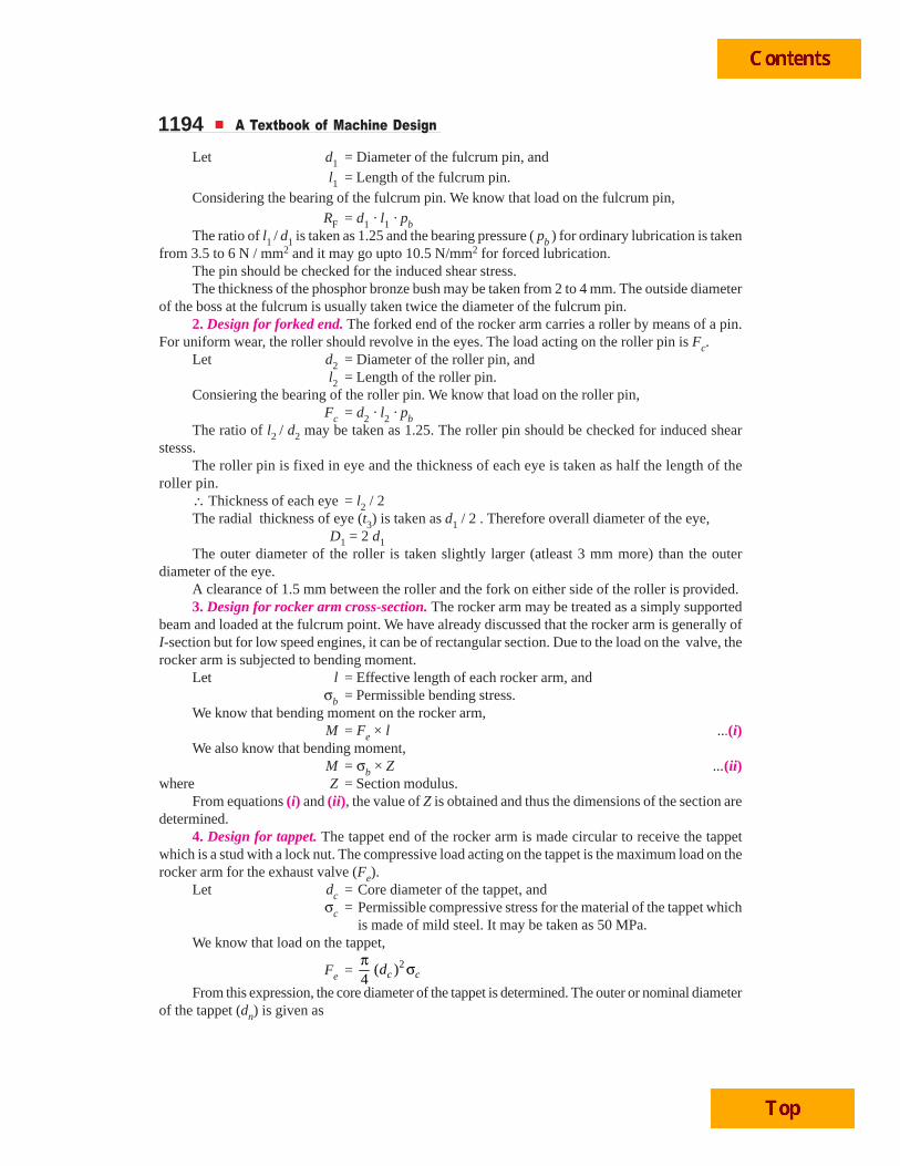
1194 A Textbook of Machine Design
Let d1 = Diameter of the fulcrum pin, andl1 = Length of the fulcrum pin.
Considering the bearing of the fulcrum pin. We know that load on the fulcrum pin,RF = d1 · l1 · pb
The ratio of l1 / d1 is taken as 1.25 and the bearing pressure ( pb ) for ordinary lubrication is takenfrom 3.5 to 6 N / mm2 and it may go upto 10.5 N/mm2 for forced lubrication.
The pin should be checked for the induced shear stress.The thickness of the phosphor bronze bush may be taken from 2 to 4 mm. The outside diameter
of the boss at the fulcrum is usually taken twice the diameter of the fulcrum pin.2. Design for forked end. The forked end of the rocker arm carries a roller by means of a pin.
For uniform wear, the roller should revolve in the eyes. The load acting on the roller pin is Fc.Let d2 = Diameter of the roller pin, and
l2 = Length of the roller pin.Consiering the bearing of the roller pin. We know that load on the roller pin,
Fc = d2 · l2 · pbThe ratio of l2 / d2 may be taken as 1.25. The roller pin should be checked for induced shear
stesss.The roller pin is fixed in eye and the thickness of each eye is taken as half the length of the
roller pin.∴ Thickness of each eye = l2 / 2The radial thickness of eye (t3) is taken as d1 / 2 . Therefore overall diameter of the eye,
D1 = 2 d1The outer diameter of the roller is taken slightly larger (atleast 3 mm more) than the outer
diameter of the eye.A clearance of 1.5 mm between the roller and the fork on either side of the roller is provided.3. Design for rocker arm cross-section. The rocker arm may be treated as a simply supported
beam and loaded at the fulcrum point. We have already discussed that the rocker arm is generally ofI-section but for low speed engines, it can be of rectangular section. Due to the load on the valve, therocker arm is subjected to bending moment.
Let l = Effective length of each rocker arm, andσb = Permissible bending stress.
We know that bending moment on the rocker arm,M = Fe × l ...(i)
We also know that bending moment,M = σb × Z ...(ii)
where Z = Section modulus.From equations (i) and (ii), the value of Z is obtained and thus the dimensions of the section are
determined.4. Design for tappet. The tappet end of the rocker arm is made circular to receive the tappet
which is a stud with a lock nut. The compressive load acting on the tappet is the maximum load on therocker arm for the exhaust valve (Fe).
Let dc = Core diameter of the tappet, andσc = Permissible compressive stress for the material of the tappet which
is made of mild steel. It may be taken as 50 MPa.We know that load on the tappet,
Fe = 2( )4 c cdπ σ
From this expression, the core diameter of the tappet is determined. The outer or nominal diameterof the tappet (dn) is given as
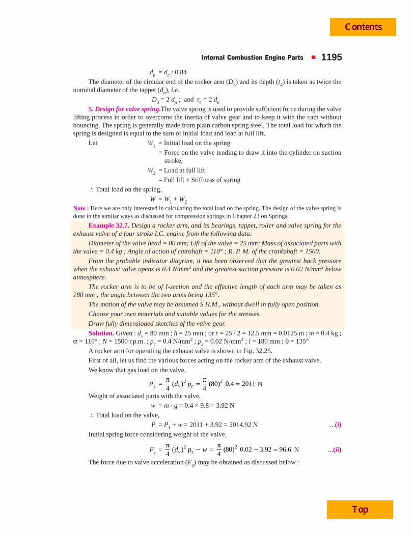
Internal Combustion Engine Parts 1195dn = dc / 0.84
The diameter of the circular end of the rocker arm (D3) and its depth (t4) is taken as twice thenominal diameter of the tappet (dn), i.e.
D3 = 2 dn ; and t4 = 2 dn
5. Design for valve spring.The valve spring is used to provide sufficient force during the valvelifting process in order to overcome the inertia of valve gear and to keep it with the cam withoutbouncing. The spring is generally made from plain carbon spring steel. The total load for which thespring is designed is equal to the sum of initial load and load at full lift.
Let W1 = Initial load on the spring
= Force on the valve tending to draw it into the cylinder on suctionstroke,
W2 = Load at full lift
= Full lift × Stiffness of spring
∴ Total load on the spring,
W = W1 + W2
Note : Here we are only interested in calculating the total load on the spring. The design of the valve spring isdone in the similar ways as discussed for compression springs in Chapter 23 on Springs.
Example 32.7. Design a rocker arm, and its bearings, tappet, roller and valve spring for theexhaust valve of a four stroke I.C. engine from the following data:
Diameter of the valve head = 80 mm; Lift of the valve = 25 mm; Mass of associated parts withthe valve = 0.4 kg ; Angle of action of camshaft = 110° ; R. P. M. of the crankshaft = 1500.
From the probable indicator diagram, it has been observed that the greatest back pressurewhen the exhaust valve opens is 0.4 N/mm2 and the greatest suction pressure is 0.02 N/mm2 belowatmosphere.
The rocker arm is to be of I-section and the effective length of each arm may be taken as180 mm ; the angle between the two arms being 135°.
The motion of the valve may be assumed S.H.M., without dwell in fully open position.
Choose your own materials and suitable values for the stresses.
Draw fully dimensioned sketches of the valve gear.
Solution. Given : dv = 80 mm ; h = 25 mm ; or r = 25 / 2 = 12.5 mm = 0.0125 m ; m = 0.4 kg ;α = 110° ; N = 1500 r.p.m. ; pc = 0.4 N/mm2 ; ps = 0.02 N/mm2 ; l = 180 mm ; θ = 135°
A rocker arm for operating the exhaust valve is shown in Fig. 32.25.
First of all, let us find the various forces acting on the rocker arm of the exhaust valve.
We know that gas load on the valve,
P1 = 2 2( ) (80) 0.4 20114 4v cd pπ π= = N
Weight of associated parts with the valve,
w = m · g = 0.4 × 9.8 = 3.92 N
∴ Total load on the valve,
P = P1 + w = 2011 + 3.92 = 2014.92 N ...(i)Initial spring force considering weight of the valve,
Fs = 2( )4 v sd p wπ − = 2(80) 0.02 3.92 96.6
4π − = N ...(ii)
The force due to valve acceleration (Fa) may be obtained as discussed below :
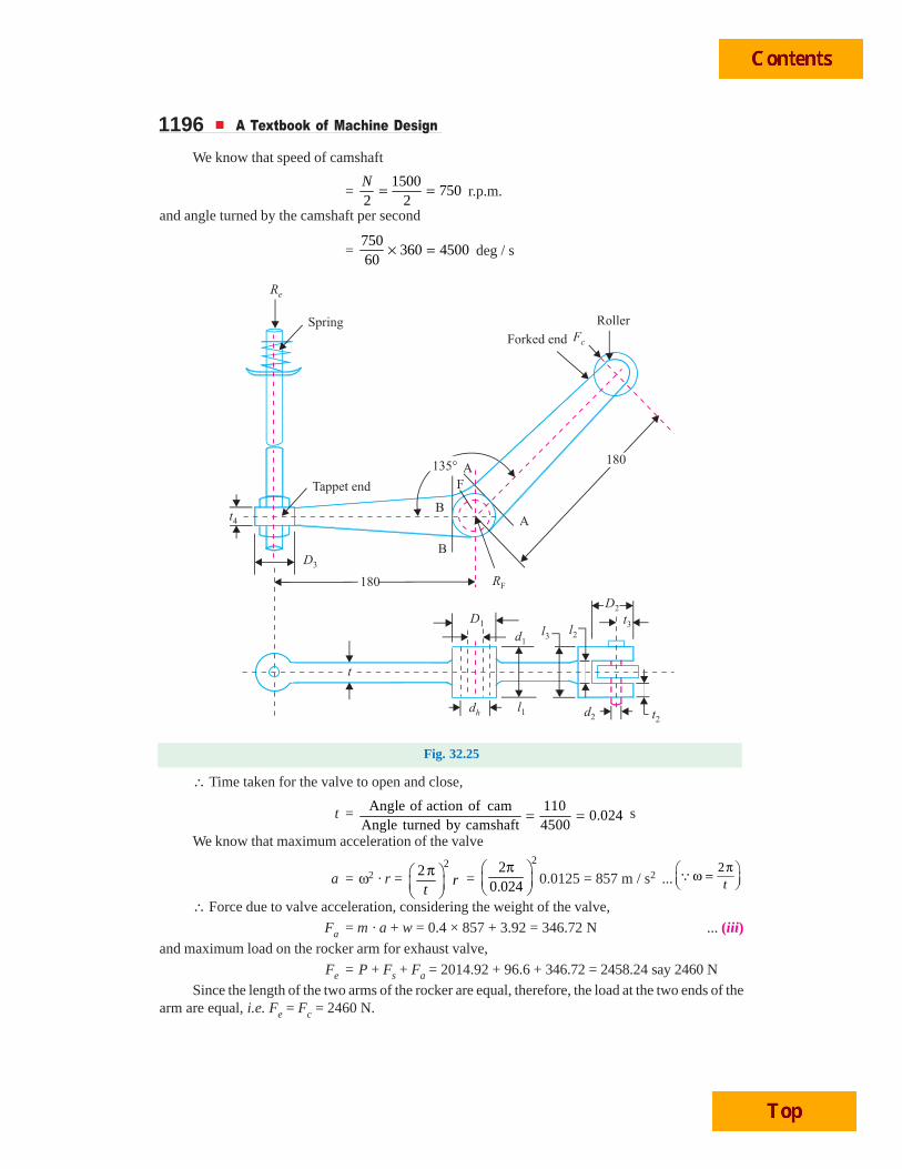
1196 A Textbook of Machine Design
We know that speed of camshaft
= 1500
7502 2N = = r.p.m.
and angle turned by the camshaft per second
= 750
360 450060
× = deg / s
Fig. 32.25
∴ Time taken for the valve to open and close,
t = Angle of action of cam 1100.024
Angle turned by camshaft 4500= = s
We know that maximum acceleration of the valve
a = ω2 · r = 2
2r
tπ⎛ ⎞
⎜ ⎟⎝ ⎠
= 2
20.024
π⎛ ⎞⎜ ⎟⎝ ⎠
0.0125 = 857 m / s2 ...2tπ⎛ ⎞ω =⎜ ⎟⎝ ⎠
Q
∴ Force due to valve acceleration, considering the weight of the valve,
Fa = m · a + w = 0.4 × 857 + 3.92 = 346.72 N ... (iii)and maximum load on the rocker arm for exhaust valve,
Fe = P + Fs + Fa = 2014.92 + 96.6 + 346.72 = 2458.24 say 2460 N
Since the length of the two arms of the rocker are equal, therefore, the load at the two ends of thearm are equal, i.e. Fe = Fc = 2460 N.
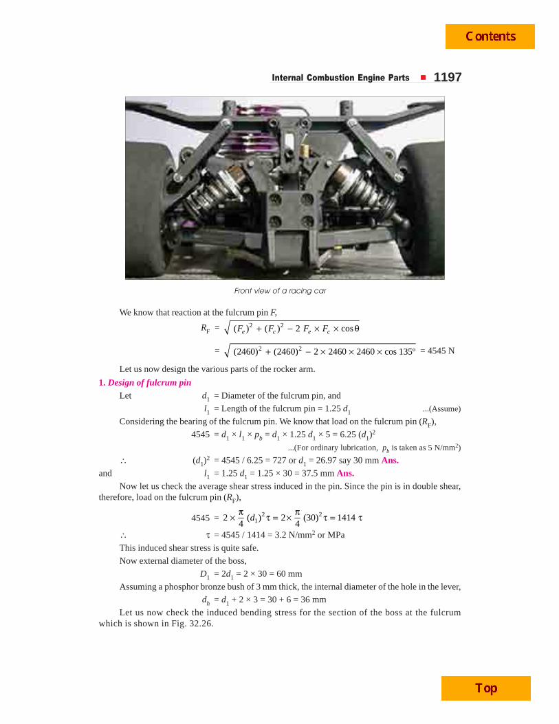
Internal Combustion Engine Parts 1197
We know that reaction at the fulcrum pin F,
RF = 2 2( ) ( ) 2 cose c e cF F F F+ − × × θ
= 2 2(2460) (2460) 2 2460 2460 cos 135º+ − × × × = 4545 N
Let us now design the various parts of the rocker arm.
1. Design of fulcrum pinLet d1 = Diameter of the fulcrum pin, and
l1 = Length of the fulcrum pin = 1.25 d1 ...(Assume)
Considering the bearing of the fulcrum pin. We know that load on the fulcrum pin (RF),
4545 = d1 × l1 × pb = d1 × 1.25 d1 × 5 = 6.25 (d1)2
...(For ordinary lubrication, pb is taken as 5 N/mm2)
∴ (d1)2 = 4545 / 6.25 = 727 or d1 = 26.97 say 30 mm Ans.
and l1 = 1.25 d1 = 1.25 × 30 = 37.5 mm Ans.Now let us check the average shear stress induced in the pin. Since the pin is in double shear,
therefore, load on the fulcrum pin (RF),
4545 = 2 212 ( ) 2 (30) 1414
4 4d
π π× τ = × τ = τ
∴ τ = 4545 / 1414 = 3.2 N/mm2 or MPa
This induced shear stress is quite safe.
Now external diameter of the boss,
D1 = 2d1 = 2 × 30 = 60 mm
Assuming a phosphor bronze bush of 3 mm thick, the internal diameter of the hole in the lever,
dh = d1 + 2 × 3 = 30 + 6 = 36 mm
Let us now check the induced bending stress for the section of the boss at the fulcrumwhich is shown in Fig. 32.26.
Front view of a racing car
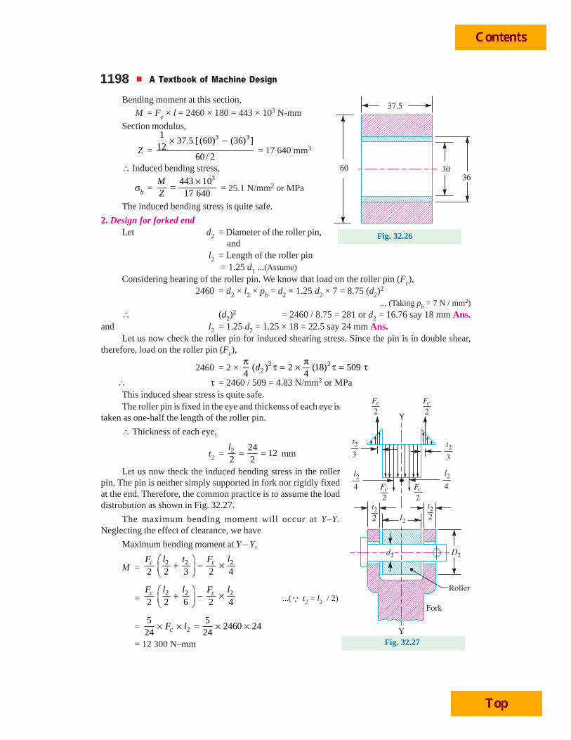
1198 A Textbook of Machine Design
Bending moment at this section,
M = Fe × l = 2460 × 180 = 443 × 103 N-mm
Section modulus,
Z =
3 3137.5 [ (60) (36) ]
1260 / 2
× − = 17 640 mm3
∴ Induced bending stress,
σb = 3443 10
17 640MZ
×= = 25.1 N/mm2 or MPa
The induced bending stress is quite safe.
2. Design for forked endLet d2 = Diameter of the roller pin,
andl2 = Length of the roller pin
= 1.25 d1 ...(Assume)
Considering bearing of the roller pin. We know that load on the roller pin (Fc),2460 = d2 × l2 × pb = d2 × 1.25 d2 × 7 = 8.75 (d2)2
... (Taking pb = 7 N / mm2)
∴ (d2)2 = 2460 / 8.75 = 281 or d2 = 16.76 say 18 mm Ans.
and l2 = 1.25 d2 = 1.25 × 18 = 22.5 say 24 mm Ans.Let us now check the roller pin for induced shearing stress. Since the pin is in double shear,
therefore, load on the roller pin (Fc),
2460 = 2 × 2 22( ) 2 (18) 509
4 4d
π πτ = × τ = τ∴ τ = 2460 / 509 = 4.83 N/mm2 or MPaThis induced shear stress is quite safe.The roller pin is fixed in the eye and thickenss of each eye is
taken as one-half the length of the roller pin.
∴ Thickness of each eye,
t2 = 2 2412
2 2l
= = mm
Let us now theck the induced bending stress in the rollerpin. The pin is neither simply supported in fork nor rigidly fixedat the end. Therefore, the common practice is to assume the loaddistrubution as shown in Fig. 32.27.
The maximum bending moment will occur at Y–Y.Neglecting the effect of clearance, we have
Maximum bending moment at Y – Y,
M = 2 2 2
2 2 3 2 4c cF Fl t l⎛ ⎞+ − ×⎜ ⎟⎝ ⎠
= 2 2 2
2 2 6 2 4c cF Fl l l⎛ ⎞+ − ×⎜ ⎟⎝ ⎠
...(Q t2 = l2 / 2)
= 25 5
2460 2424 24cF l× × = × ×
= 12 300 N–mm
Fig. 32.26
Fig. 32.27
Internal Combustion Engine Parts 1199and section modulus of the pin,
Z =3 3 3
2( ) (18) 573 mmdπ π= =32 32
∴ Bending stress induced in the pin
=212300
21.5 N/mm or MPa573
M
Z= =
This bending stress induced in the pin is within permissible limits.
Since the radial thickness of eye (t3) is taken as d2 / 2, therefore, overall diameter of the eye,
D2 = 2 d2 = 2 × 18 = 36 mm
The outer diameter of the roller is taken slightly larger (atleast 3 mm more) than the outerdiameter of the eye.
In the present case, 42 mm outer diameter of the roller will besufficient.
Providing a clearance of 1.5 mm between the roller and thefork on either side of the roller, we have
l3 = 22 2 2 1.5
2
tl + × + ×
=12
24 2 3 39 mm2
+ × + =
3. Design for rocker arm cross-sectionThe cross-section of the roker arm is obtained by considering
the bending of the sections just near the boss of fulcrum on bothsides, such as section A – A and B – B.
We know that maximum bending moment at A – A and B – B.
M = 3602460 180 369 10 N-mm
2⎛ ⎞− = ×⎜ ⎟⎝ ⎠
The rocker arm is of I-section. Let us assume the proportions as shown in Fig. 32.28. We knowthat section modulus,
Z =
3 34
3
12.5 (6 ) 1.5 (4 ) 3712 12.33
6 / 2 3
t t t t tt
t t
⎡ ⎤−⎣ ⎦= =
∴ Bending stress (σb),
70 =3 3
3 3
369 10 29.93 10
12.33
M
Z t t
× ×= =
t3 = 29.93 × 10³ / 70 = 427.6 or t = 7.5 say 8 mm
∴ Width of flange = 2.5 t = 2.5 × 8 = 20 mm Ans.Depth of web = 4 t = 4 × 8 = 32 mm Ans.
and depth of the section = 6 t = 6 × 8 = 48 mm Ans.Normally thickness of the flange and web is constant throughout, whereas the width and depth
is tapered.
4. Design for tappet screwThe adjustable tappet screw carries a compressive load of Fe = 2460 N. Assuming the screw is
made of mild steel for which the compressive stress (σc) may be taken as 50 MPa.
Fig. 32.28
1200 A Textbook of Machine Design
Let dc = Core diameter of the tappet screw.
We know that the load on the tappet screw (Fe),
2460 = 2 2 2( ) ( ) 50 39.3 ( )c c c cd d dπ πσ = =4 4
∴ (dc)2 = 2460 / 39.3 = 62.6 or dc = 7.9 say 8 mm
and outer or nominal diameter of the screw,
d =8
9.52 say 10 mm0.84 0.84
cd= = Ans.
We shall use 10 mm stud and it is provided with a lock nut. The diameter of the circular end ofthe arm (D3) and its depth (t4) is taken as twice the diameter of stud.
∴ D3 = 2 × 10 = 20 mm Ans.and t4 = 2 × 10 = 20 mm Ans.5. Design for valve spring
First of all, let us find the total load on the valve spring.We know that initial load on the spring,
W1 = Initial spring force (Fs) = 96.6 N ...(Already calculated)
and load at full lift,W2 = Full valve lift × Stiffiness of spring (s)
= 25 × 10 = 250 N ...(Assuming s = 10 N/mm)
∴ Total load on the spring,W = W1 + W2 = 96.6 + 250 = 346.6 N
Now let us find the various dimensions for the valve spring, as discussed below:(a) Mean diameter of spring coil
Let D = Mean diameter of the spring coil, andd = Diameter of the spring wire.
We know that Wahl’s stress factor,
K =4 1 0.615 4 8 1 0.615
1.1844 4 4 8 4 8
C
C C
− × −+ = + =− × −
...(Assuming C = D/d = 8)
and maximum shear stress (τ),
420 = 2 2
8 8 346.6 8 83601.184
WCK
d d d2× ×× = × =
π π...(Assuming τ = 420 MPa or N/mm2)
∴ d 2 = 8360 / 420 = 19.9 or d = 4.46 mmThe standard size of the wire is SWG 7 having diameter ( d ) = 4.47 mm. Ans. (See Table 22.2).∴ Mean diameter of the spring coil,
D = C · d = 8 × 4.47 = 35.76 mm Ans.and outer diameter of the spring coil,
Do = D + d = 35.76 + 4.47 = 40.23 mm Ans.(b) Number of turns of the coil
Let n = Number of active turns of the coil.
We know that maximum compression of the spring,
δ = 38 · ·
·W C n
G d or
38 ··
C nW G dδ =
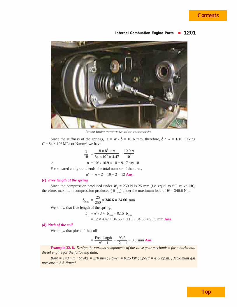
Internal Combustion Engine Parts 1201
Since the stiffness of the springs, s = W / δ = 10 N/mm, therefore, δ / W = 1/10. TakingG = 84 × 103 MPa or N/mm2, we have
110
= 3
3 3
8 8 10.9
84 10 4.47 10
n n× × =× ×
∴ n = 103 / 10.9 × 10 = 9.17 say 10
For squared and ground ends, the total number of the turns,
n′ = n + 2 = 10 + 2 = 12 Ans.
(c) Free length of the spring
Since the compression produced under W2 = 250 N is 25 mm (i.e. equal to full valve lift),therefore, maximum compression produced ( δ max) under the maximum load of W = 346.6 N is
δmax = 25
346.6 34.66250
× = mm
We know that free length of the spring,
LF = n′ · d + δmax + 0.15 δmax
= 12 × 4.47 + 34.66 + 0.15 × 34.66 = 93.5 mm Ans.
(d) Pitch of the coil
We know that pitch of the coil
= Free length 93.5
8.5' 1 12 1n
= =− −
mm Ans.
Example 32. 8. Design the various components of the valve gear mechanism for a horizontaldiesel engine for the following data:
Bore = 140 mm ; Stroke = 270 mm ; Power = 8.25 kW ; Speed = 475 r.p.m. ; Maximum gaspressure = 3.5 N/mm2
Power-brake mechanism of an automobile
1202 A Textbook of Machine Design
The valve opens 33º before outer dead cerntre and closes 1º after inner dead centre. It opensand closes with constant acceleration and decleration for each half of the lift. The length of therocker arm on either side of the fulcrum is 150 mm and the included angle is 160º. The weight of thevalve is 3 N.
Solution. Given : D = 140 mm = 0.14 m ; L = 270 mm = 0.27 m ; Power = 8.25 kW = 8250 W ;N = 475 r.p.m ; p = 3.5 N/mm2 ; l = 150 mm = 0.15 m ; θ = 160° ; w = 3 N
First of all, let us find out dimensions of the valve as discussed below :
Size of the valve port
Let dp = Diameter of the valve port, and
ap = Area of the valve port = 2( )
4 pdπ
We know that area of the piston,
a = 2 2 2(0.14) 0.0154m4 4
Dπ π= =
and mean velocity of the piston,
v = 2 2 0.27 475
4.27560 60L N × ×= = m / s
From Table 32.3, let us take the mean velocity of the gas through the port (vp) as 40 m/s.
We know that ap .vp = a.v
2( ) 404 pdπ
= 0.0154 × 4.275 or 31.42 (dp)2 = 0.0658
∴ (dp)2 = 0.0658 / 31.42 = 2.09 × 10⁻³ or dp = 0.045 m = 45 mm Ans.
Maximum lift of the valve
We know that maximum lift of the valve,
h = 45
4 cos 4 cos 45ºpd
=α = 15.9 say 16 mm Ans.
...(Taking α = 45º)
Thickness of the valve head
We know that thickness of valve head,
t = k · dp 3.5
0.42 45 4.7256b
p = × =σ
mm Ans.
...(Taking k = 0.42 and σb = 56 MPa)
Valve stem diameter
We know that valve stem diameter,
ds = 45
6.35 mm8 8pd
+ = + 6.35 = 11.97 say 12 mm Ans.
Valve head diameter
The projected width of the valve seat, for a seat angle of 45º, may be empirically taken as0.05 dp to 0.07 dp. Let us take width of the valve seat as 0.06 dp i.e. 0.06 × 45 = 2.7 mm.
∴ Valve head diameter, dv = dp + 2 × 2.7 = 45 + 5.4 = 50.4 say 51 mm Ans.Now let us calculate the various forces acting on the rocker arm of exhaust valve.
Internal Combustion Engine Parts 1203We know that gas load on the valve,
P1 = 2 2( ) (51) 0.4 8174 4v cd pπ π= = N ...(Taking pc = 0.4 N/mm2)
Total load on the valve, considering the weight of the valve,
P = P1 + w = 817 + 3 = 820 N
Initial spring force, considering the weight of the valve,
Fs = 2 2( ) (51) 0.025 3 484 4v sd p wπ π− = − = N
...(Taking ps = 0.025 N/mm2)
The force due to acceleration (Fa) may be obtained as discussed below :
We know that total angle of crank for which the valve remains open
= 33 + 180 + 1 = 214º
Since the engine is a four stroke engine, therefore the camshaft angle for which the valveremains open
= 214 / 2 = 107º
Now, when the camshaft turns through 107 / 2 = 53.5°, the valve lifts by a distance of 16 mm. Itmay be noted that the half of this period is occupied by constant acceleration and half by constantdecleration. The same process occurs when the valve closes. Therefore, the period for constantacceleration is equal to camshaft rotation of 53.5 / 2 = 26.75 º and during this time, the valve liftsthrough a distance of 8 mm.
We know that speed of camshaft
= 475
2 2N = = 237.5 r.p.m.
∴ Angle turned by the camshaft per second
= 237.5
36060
× = 1425 deg / s
and time taken by the camshaft for constant acceleration,
t = 26.75
0.01881425
= s
Let a = Acceleration of the valve.
We know that s = u . t + 12
a.t2 ... (Equation of motion)
8 = 0 × t + 2 41(0.0188) 1.767 10
2a −= × a ...(Q u = o)
∴ a = 8 / 1.767 × 10–4 = 45 274 mm / s2 = 45.274 m / s2
and force due to valve acceleration, considering the weight of the valve,
Fa = m · a + w = 3
9.81 × 45.274 + 3 = 16.84 N ... (Q m = w/g)
We know that the maximum load on the rocker arm for exhaust valve,
Fe = P + Fs + Fa = 820 + 48 + 16.84 = 884.84 say 885 N
Since the length of the two arms of the rocker are equal, therefore, load at the two ends of thearm are equal, i.e. Fe = Fc = 885 N.
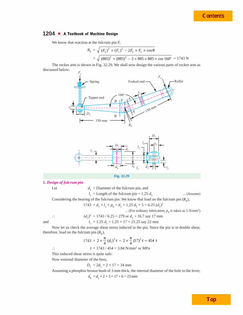
1204 A Textbook of Machine Design
We know that reaction at the fulcrum pin F,
RF = 2 2( ) ( ) 2 cose c e cF F F F+ − × × θ
= 2 2(885) (885) 2 885 885 cos 160º+ − × × × = 1743 N
The rocker arm is shown in Fig. 32.29. We shall now design the various parts of rocker arm asdiscussed below:
Fig. 32.29
1. Design of fulcrum pinLet d1 = Diameter of the fulcrum pin, and
l1 = Length of the fulcrum pin = 1.25 d1 ... (Assume)
Considering the bearing of the fulcrum pin. We know that load on the fulcrum pin (RF),
1743 = d1 × l1 × pb = d1 × 1.25 d1 × 5 = 6.25 (d1)2
... (For ordinary lubrication, pb is taken as 5 N/mm2)
∴ (d1)2 = 1743 / 6.25 = 279 or d1 = 16.7 say 17 mm
and l1 = 1.25 d1 = 1.25 × 17 = 21.25 say 22 mm
Now let us check the average shear stress induced in the pin. Since the pin is in double shear,therefore, load on the fulcrum pin (RF),
1743 = 212 ( )
4d
π× τ = 22 (17) 4544π× τ = τ
∴ τ = 1743 / 454 = 3.84 N/mm2 or MPa
This induced shear stress is quite safe.
Now external diameter of the boss,
D1 = 2d1 = 2 × 17 = 34 mm
Assuming a phosphor bronze bush of 3 mm thick, the internal diameter of the hole in the lever,
dh = d1 + 2 × 3 = 17 + 6 = 23 mm
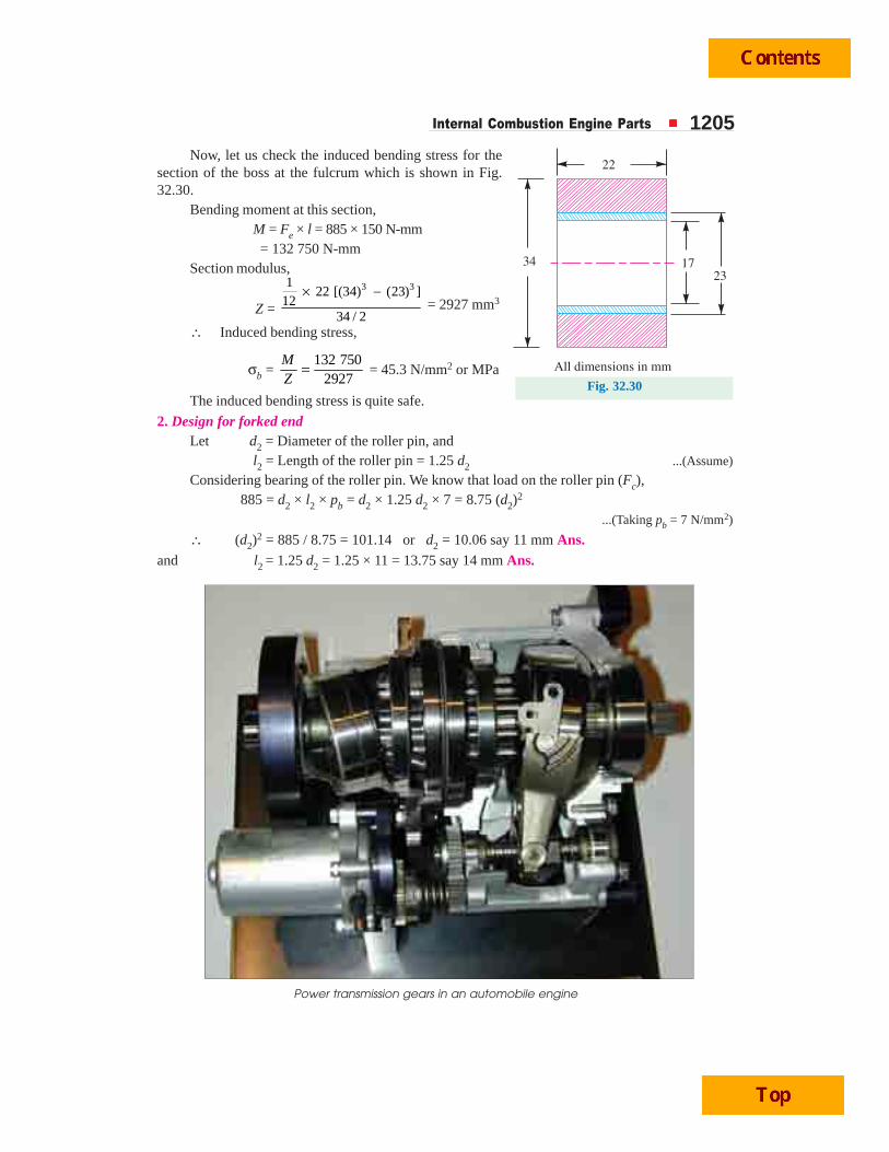
Internal Combustion Engine Parts 1205Now, let us check the induced bending stress for the
section of the boss at the fulcrum which is shown in Fig.32.30.
Bending moment at this section, M = Fe × l = 885 × 150 N-mm = 132 750 N-mm
Section modulus,
Z =
3 3122 [(34) (23) ]
1234 / 2
× − = 2927 mm3
∴ Induced bending stress,
σb = 132 750
2927MZ
= = 45.3 N/mm2 or MPa
The induced bending stress is quite safe.
2. Design for forked endLet d2 = Diameter of the roller pin, and
l2 = Length of the roller pin = 1.25 d2 ...(Assume)
Considering bearing of the roller pin. We know that load on the roller pin (Fc), 885 = d2 × l2 × pb = d2 × 1.25 d2 × 7 = 8.75 (d2)
2
...(Taking pb = 7 N/mm2)
∴ (d2)2 = 885 / 8.75 = 101.14 or d2 = 10.06 say 11 mm Ans.
and l2 = 1.25 d2 = 1.25 × 11 = 13.75 say 14 mm Ans.
Fig. 32.30
Power transmission gears in an automobile engine
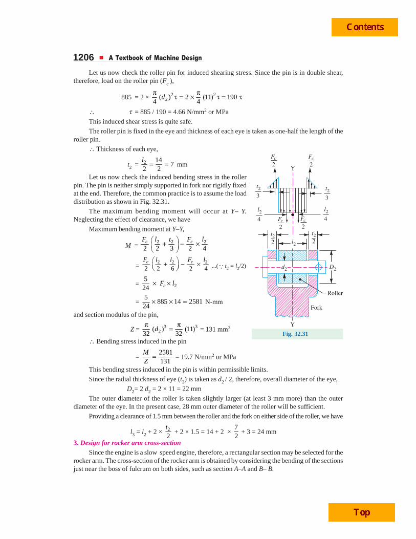
1206 A Textbook of Machine Design
Let us now check the roller pin for induced shearing stress. Since the pin is in double shear,therefore, load on the roller pin (Fc ),
885 = 2 × 2 22( ) 2 (11) 190
4 4d
π πτ = × τ = τ
∴ τ = 885 / 190 = 4.66 N/mm2 or MPa
This induced shear stress is quite safe.
The roller pin is fixed in the eye and thickness of each eye is taken as one-half the length of theroller pin.
∴ Thickness of each eye,
t2 = 2 147
2 2l
= = mm
Let us now check the induced bending stress in the rollerpin. The pin is neither simply supported in fork nor rigidly fixedat the end. Therefore, the common practice is to assume the loaddistribution as shown in Fig. 32.31.
The maximum bending moment will occur at Y– Y.Neglecting the effect of clearance, we have
Maximum bending moment at Y–Y,
M = 2 2 2
2 2 3 2 4c cF Fl t l⎛ ⎞+ − ×⎜ ⎟⎝ ⎠
= 2 2 2
2 2 6 2 4c cF Fl l l⎛ ⎞+ − ×⎜ ⎟⎝ ⎠ ...(Q t2 = l2/2)
= 2524 cF l× ×
= 5
885 14 258124
× × = N-mm
and section modulus of the pin,
Z = 3 32( ) (11)
32 32d
π π= = 131 mm3
∴ Bending stress induced in the pin
= 2581131
MZ
= = 19.7 N/mm2 or MPa
This bending stress induced in the pin is within permissible limits.
Since the radial thickness of eye (t3) is taken as d2 / 2, therefore, overall diameter of the eye,
D2= 2 d2 = 2 × 11 = 22 mm
The outer diameter of the roller is taken slightly larger (at least 3 mm more) than the outerdiameter of the eye. In the present case, 28 mm outer diameter of the roller will be sufficient.
Providing a clearance of 1.5 mm between the roller and the fork on either side of the roller, we have
l3 = l2 + 2 × 2
2t
+ 2 × 1.5 = 14 + 2 × 72
+ 3 = 24 mm
3. Design for rocker arm cross-sectionSince the engine is a slow speed engine, therefore, a rectangular section may be selected for the
rocker arm. The cross-section of the rocker arm is obtained by considering the bending of the sectionsjust near the boss of fulcrum on both sides, such as section A–A and B– B.
Fig. 32.31
Internal Combustion Engine Parts 1207Let t1 = Thickness of the rocker arm which is uniform throughout.
B = Width or depth of the rocker arm which varies from boss diameterof fulcrum to outside diameter of the eye (for the forked end side)and from boss diameter of fulcrum to thickness t3 (for the tappet orstud end side).
Now bending moment on section A – A and B – B,
M = 88534
1502
⎛ ⎞−⎜ ⎟⎝ ⎠
= 117 705 N-mm
and section modulus at A – A and B – B,
Z = 2 21 1 1
1 1 1· ( )
6 6 6t B t D× = × = × t1 (34)2 = 193 t1
...(At sections A–A and B–B, B = D)We know that bending stress (σb),
70 = 1
117 705193
MZ t
= ...(Taking σb = 70 MPa or N/mm2)
∴ t1 = 117 705 / 193 × 70 = 8.7 say 10 mm Ans.4. Design for tappet screw
The adjustable tappet screw carries a compressive load of Fe = 885 N. Assuming the screw tobe made of mild steel for which the compressive stress (σc) may be taken as 50 MPa.
Let dc = Core diameter of the tappet screw.
We know that load on the tappet screw (Fe),
885 = 2 2 2( ) ( ) 50 39.3( )4 4c c c cd d dπ πσ = =
∴ (dc )2 = 885 / 39.3 = 22.5 or dc = 4.74 say 5 mm Ans.
and outer or nominal diameter of the screw,
d = 5
0.84 0.8cd
= = 6.25 say 6.5 mm Ans.
We shall use 6.5 mm stud and it is provided with a lock nut. The diameter of the circular end ofthe arm (D3) and its depth (t4) is taken as twice the diameter of stud.
∴ D3 = 2 × 6.5 = 13 mm Ans.and t4 = 2 × 6.5 = 13 mm Ans.5. Design for valve spring
First of all, let us find the total load on the valve spring.
We know that intial load on the spring,
W1 = Initial spring force (Fs) = 48 N ...(Already calculated)
and load at full lift, W2 = Full valve lift × Stiffness of spring (s)
= 16 × 8 = 128 N ...(Taking s = 8 N/mm)
∴ Total load on the spring,
W = W1 + W2 = 48 + 128 = 176 N
Now let us find the various dimensions for the valve spring as discussed below:
(a) Mean diameter of the spring coilLet D = Mean diameter of the spring coil, and
d = Diameter of the spring wire.
1208 A Textbook of Machine Design
We know that Wahl’s stress factor,
K = 4 1 0.615 4 6 1 0.6154 4 4 6 4 6
CC C
− × −+ = +− × − = 1.2525
...(Assuming C = D/d = 6)
and maximum shear stress (τ),
420 = K × 2 2 2
8 8 176 6 33681.2525
WC
d d d
× ×= × =π π
∴ d2 = 3368 / 420 = 8.02 or d = 2.83 mmThe standard size of the wire is SWG 11 having a diameter (d ) = 2.946 mm Ans.
(see Table 22.2)∴ Mean diameter of spring coil,
D = C · d = 6 × 2.946 = 17.676 mm Ans.and outer diameter of the spring coil,
Do = D + d = 17.676 + 2.946 = 20.622 mm Ans.(b) Number of turns of the coil
Let n = Number of turns of the coil,We know that maximum compression of the spring.
δ = 38 · ·
·W C n
G d or 38 ··
C nW G dδ =
Inside view of an automobile
Internal Combustion Engine Parts 1209Since the stiffness of the spring, s = W / δ = 8 N / mm, therefore δ / W = 1 / 8. Taking
G = 84 × 103 MPa or N/mm2, we have
18
= 3
3 3
8 6 6.98
84 10 2.946 10
n n× × =× ×
∴ n = 103 / 8 × 6.98 = 17.9 say 18
For squared and ground ends, the total number of turns,
n′ = n + 2 = 18 + 2 = 20 Ans.(c) Free length of the spring
Since the compression produced under W2 = 128 N is 16 mm, therefore, maximum compressionproduced under the maximum load of W = 176 N is
δmax = 16
176128
× = 22 mm
We know that free length of the spring,
LF = n′. d + δmax + 0.15 δmax
= 20 × 2.946 + 22 + 0.15 × 22 = 84.22 say 85 mm Ans.(d) Pitch of the coil
We know that pitch of the coil
= Free length
1n′ − = 85
20 1− = 4.47 mm Ans.
Design of camThe cam is forged as one piece with the camshaft. It is designed as discussed below :The diameter of camshaft (D′) is taken empirically as
D′ = 0.16 × Cylinder bore + 12.7 mm= 0.16 × 140 + 12.7 = 35.1 say 36 mm
The base circle diameter is about 3 mm greater than the camshaft diameter.
∴ Base circle diameter = 36 + 3 = 39 say 40 mm
The width of cam is taken equal to the width of roller, i.e. 14 mm.
The width of cam (w′) is also taken empirically as
w ′ = 0.09 × Cylinder bore + 6 mm = 0.09 × 140 +6 = 18.6 mm
Let us take the width of cam as 18 mm.
Now the *cam is drawn according to the procedure given below :
First of all, the displacement diagram, as shown in Fig. 32.32, is drawn as discussed in thefollowing steps :
1. Draw a horizontal line ANM such that AN represents the angular displacement when valveopens (i.e. 53.5º) to some suitable scale. The line NM represents the angular displacementof the cam when valve closes (i.e. 53.5º).
2. Divide AN and NM into any number of equal even parts (say six).
3. Draw vertical lines through points 0, 1, 2, 3 etc. equal to the lift of valve i.e. 16 mm.
4. Divide the vertical lines 3 – f and 3′ – f ′ into six equal parts as shown by points a, b, c ... anda′, b′, c′ .... in Fig. 32.32.
5. Since the valve moves with equal uniform acceleration and decleration for each half of thelift, therefore, valve displacement diagram for opening and closing of valve consists ofdouble parabola.
* For complete details, refer Authors’ popular book on ‘Theory of Machines’.
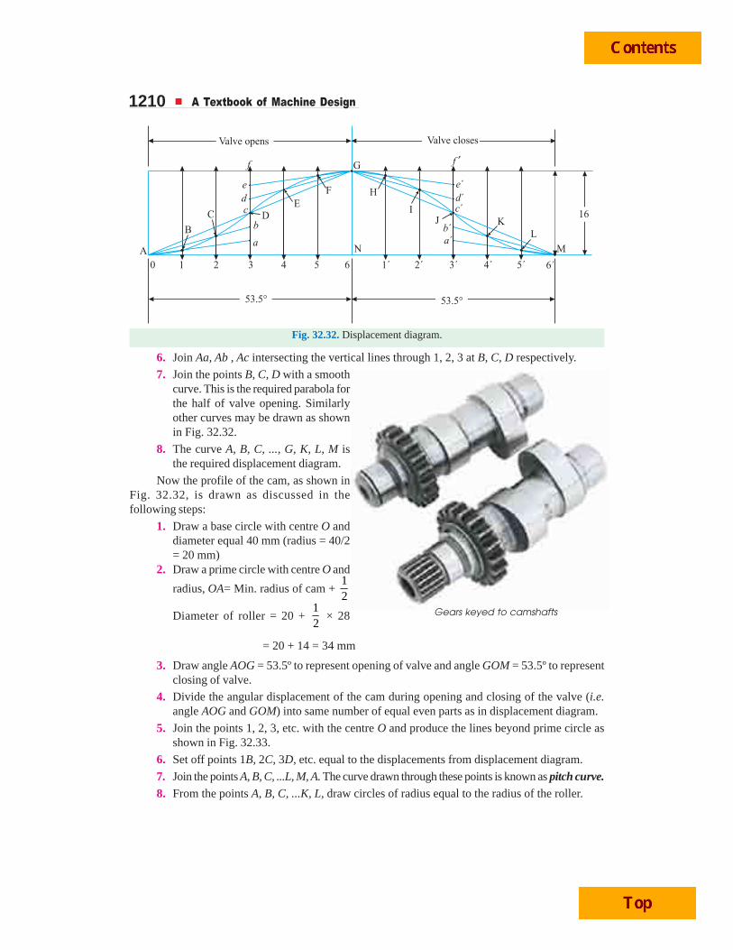
1210 A Textbook of Machine Design
Fig. 32.32. Displacement diagram.
6. Join Aa, Ab , Ac intersecting the vertical lines through 1, 2, 3 at B, C, D respectively.
7. Join the points B, C, D with a smoothcurve. This is the required parabola forthe half of valve opening. Similarlyother curves may be drawn as shownin Fig. 32.32.
8. The curve A, B, C, ..., G, K, L, M isthe required displacement diagram.
Now the profile of the cam, as shown inFig. 32.32, is drawn as discussed in thefollowing steps:
1. Draw a base circle with centre O anddiameter equal 40 mm (radius = 40/2= 20 mm)
2. Draw a prime circle with centre O and
radius, OA= Min. radius of cam + 12
Diameter of roller = 20 + 12
× 28
= 20 + 14 = 34 mm
3. Draw angle AOG = 53.5º to represent opening of valve and angle GOM = 53.5º to representclosing of valve.
4. Divide the angular displacement of the cam during opening and closing of the valve (i.e.angle AOG and GOM) into same number of equal even parts as in displacement diagram.
5. Join the points 1, 2, 3, etc. with the centre O and produce the lines beyond prime circle asshown in Fig. 32.33.
6. Set off points 1B, 2C, 3D, etc. equal to the displacements from displacement diagram.
7. Join the points A, B, C, ...L, M, A. The curve drawn through these points is known as pitch curve.8. From the points A, B, C, ...K, L, draw circles of radius equal to the radius of the roller.
Gears keyed to camshafts
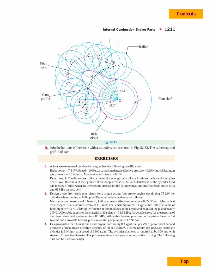
Internal Combustion Engine Parts 1211
Fig. 32.33
9. Join the bottoms of the circle with a smooth curve as shown in Fig. 32.33. The is the requiredprofile of cam.
EEEEEXEXEXEXEXERRRRRCISECISECISECISECISESSSSS
1. A four stroke internal combustion engine has the following specifications:Brake power = 7.5 kW; Speed = 1000 r.p.m.; Indicated mean effective pressure = 0.35 N/mm2;Maximumgas pressure = 3.5 N/mm2; Mechanical efficiency = 80 %.Determine: 1. The dimesions of the cylinder, if the length of stroke is 1.4 times the bore of the cylin-der; 2. Wall thickness of the cylinder, if the hoop stress is 35 MPa; 3. Thickness of the cylinder headand the size of studs when the permissible stresses for the cylinder head and stud materials are 45 MPaand 65 MPa respectively.
2. Design a cast iron trunk type piston for a single acting four stroke engine developing 75 kW percylinder when running at 600 r.p.m. The other avialable data is as follows:Maximum gas pressure = 4.8 N/mm2; Indicated mean effective pressure = 0.65 N/mm2; Mechanicalefficiency = 95%; Radius of crank = 110 mm; Fuel consumption = 0.3 kg/BP/hr; Calorific value offuel (higher) = 44 × 103kJ/kg; Difference of temperatures at the centre and edges of the piston head =200ºC; Allowable stress for the material of the piston = 33.5 MPa; Allowable stress for the material ofthe piston rings and gudgeon pin = 80 MPa; Allowable bearing pressure on the piston barrel = 0.4N/mm2 and allowable bearing pressure on the gudgeon pin = 17 N/mm2.
3. Design a piston for a four stroke diesel engine consuming 0.3 kg of fuel per kW of power per hour andproduces a brake mean effective pressure of the 0.7 N/mm2. The maximum gas pressure inside thecylinder is 5 N/mm2 at a speed of 3500 r.p.m. The cylinder diameter is required to be 300 mm withstroke 1.5 times the diameter. The piston may have 4 compression rings and an oil ring. The followingdata can be used for design:
1212 A Textbook of Machine Design
Higher calorific value of fuel = 46 × 103kJ/kg; Temperature at the piston centre = 700 K; Tempressureat the piston edge = 475 K; Heat conductivity factor = 46.6 W/m/K; Heat conducted through top = 5%of heat produced; Permissible tensile strength for the material of piston = 27 N/mm2; Pressurebetween rings and piston = 0.04 N/mm2; Permissible tensile stress in rings = 80 N/mm2; PermissiblePressure on piston barrel = 0.4 N/mm2; Permissible pressure on piston pin = 15 N/mm2; Permissiblestress in piston pin = 85 N/mm2.
Any other data required for the design may be assumed.
4. Determine the dimensions of an I-section connecting rod for a petrol engine from the following data:
Diameter of the piston = 110 mm; Mass of the reciprocating parts = 2 kg; Length of the connectingrod from centre to centre = 325 mm; Stroke length = 150 mm; R.P.M. = 1500 with possible overspeedof 2500; Compression ratio = 4 : 1; Maximum explosion pressure = 2.5 N/mm2.
5. The following particulars refer to a four stroke cycle diesel engine:
Cylinder bore = 150 mm; Stroke = 187.5 mm; R.P.M. = 1200; Maximum gas pressure = 5.6 N/mm2;Mass of reciprocating parts = 1.75 kg.
1. The dimensions of an I-section connecting rod of forged steel with an elastic limit compressivestress of 350 MPa. The ratio of the length of connecting rod to the length of crank is 4 and thefactor of safety may be taken as 5;
2. The wrist pin and crankpin dimensions on the basis of bearing pressures of 10 N/mm2 and 6.5N/mm2 of the projected area respectively; and
3. The dimensions of the small and big ends of the connecting rods, including the size of thesecuring bolts of the crankpin end. Assume that the allowable stress in the bolts, is not to exceed35 N/mm2.
Draw dimensioned sketches of the connecting rod showing the provisions for lubrication.
6. A connecting rod is required to be designed for a high speed, four stroke I.C. engine. The followingdata are available.
Diameter of piston = 88 mm; Mass of reciprocating parts = 1.6 kg; Length of connecting rod (centre tocentre) = 300 mm; Stroke = 125 mm; R.P.M. = 2200 (when developing 50 kW); Possible overspeed =3000 r.p.m.; Compression ratio = 6.8 : 1 (approximately); Probale maximum explosion pressure(assumed shortly after dead centre, say at about 3°) = 3.5 N/mm2.
Draw fully dimensioned drawings of the connecting rod showing the provision for the lubrication.
7. Design a plain carbon steel centre crankshaft for a single acting four stroke, single cylinder engine forthe following data:
Piston diameter = 250 mm; Stroke = 400 mm; Maximum combustion pressure = 2.5 N/mm2; Weightof the flywheel = 16 kN; Total belt pull = 3 N; Length of connecting rod = 950 mm.
When the crank has turned through 30° from top dead centre, the pressure on the piston is 1 N/mm2
and the torque on the crank is maximum.
Any other data required for the design may be assumed.
8. Design a side crankshaft for a 500 mm × 600 mm gas engine. The weight of the flywheel is 80 kN andthe explosion pressure is 2.5 N/mm2. The gas pressure at maximum torque is 0.9 N/mm2 when thecrank angle. is 30º. The connecting rod is 4.5 times the crank radius.
Any other data required for the design may be assumed.
9. Design a rocker arm of I-section made of cast steel for operating an exhaust valve of a gas engine. Theeffective length of the rocker arm is 250 mm and the angle between the arm is 135°. The exhaust valveis 80 mm in diameter and the gas pressure when the valve begins to open is 0.4 N/mm2. The greatestsuction pressure is 0.03 N/mm2 below atmospheric. The initial load may be assumed as 0.05 N/mm2
of valve area and the valve inertia and friction losses as 120 N. The ultimate strength of cast steel is750 MPa. The allowable bearing pressure is 8 N/mm2 and the permissible stress in the material is 72MPa.
10. Design the various components of a valve gear mechanism for a horizontal diesel engine having thefollowing specifications:
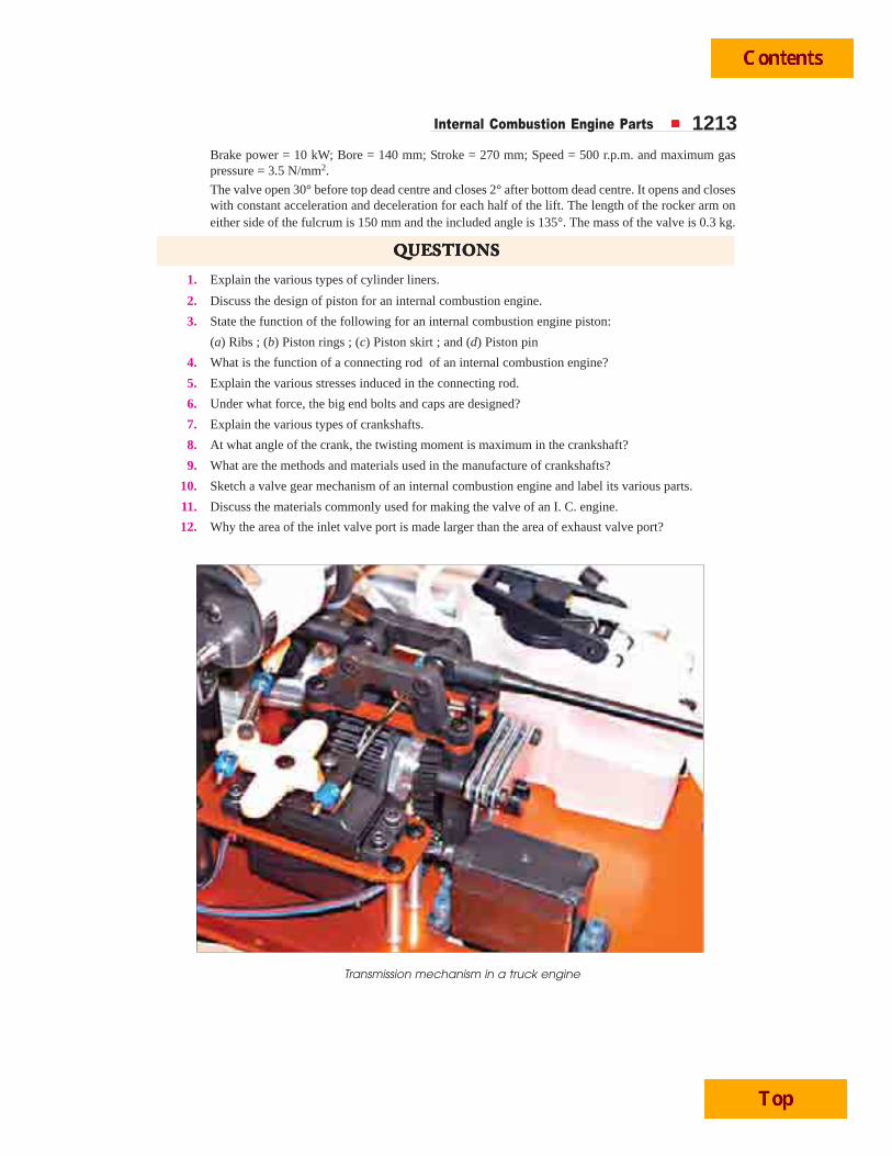
Internal Combustion Engine Parts 1213Brake power = 10 kW; Bore = 140 mm; Stroke = 270 mm; Speed = 500 r.p.m. and maximum gaspressure = 3.5 N/mm2.
The valve open 30° before top dead centre and closes 2° after bottom dead centre. It opens and closeswith constant acceleration and deceleration for each half of the lift. The length of the rocker arm oneither side of the fulcrum is 150 mm and the included angle is 135°. The mass of the valve is 0.3 kg.
QQQQQUEUEUEUEUESTSTSTSTSTIONSIONSIONSIONSIONS
1. Explain the various types of cylinder liners.
2. Discuss the design of piston for an internal combustion engine.
3. State the function of the following for an internal combustion engine piston:
(a) Ribs ; (b) Piston rings ; (c) Piston skirt ; and (d) Piston pin
4. What is the function of a connecting rod of an internal combustion engine?
5. Explain the various stresses induced in the connecting rod.
6. Under what force, the big end bolts and caps are designed?
7. Explain the various types of crankshafts.
8. At what angle of the crank, the twisting moment is maximum in the crankshaft?
9. What are the methods and materials used in the manufacture of crankshafts?
10. Sketch a valve gear mechanism of an internal combustion engine and label its various parts.
11. Discuss the materials commonly used for making the valve of an I. C. engine.
12. Why the area of the inlet valve port is made larger than the area of exhaust valve port?
Transmission mechanism in a truck engine
1214 A Textbook of Machine Design
OBJECTOBJECTOBJECTOBJECTOBJECTIVEIVEIVEIVEIVE TTTTTYPYPYPYPYPE E E E E QQQQQUEUEUEUEUESTSTSTSTSTIONSIONSIONSIONSIONS
1. The cylinders are usually made of
(a) cast iron or cast steel (b) aluminium
(c) stainless steel (d) copper
2. The length of the cylinder is usually taken as
(a) equal to the length of piston (b) equal to the length of stroke
(c) equal to the cylinder bore (d) 1.5 times the length of stroke
3. The skirt of piston
(a) is used to withstand the pressure of gas in the cylinder
(b) acts as a bearing for the side thrust of the connecting rod
(c) is used to seal the cylinder in order to prevent leakage of the gas past the piston
(d) none of the above
4. The side thrust on the cylinder liner is usually taken as ........... of the maximum gas load on the piston.
(a) 1/5 (b) 1/8
(c) 1/10 (d) 1/5
5. The length of the piston usually varies between
(a) D and 1.5 D (b) 1.5 D and 2 D
(c) 2D and 2.5 D (d) 2.5 D and 3 D
where D = Diameter of the piston.
6. In designing a connecting rod, it is considered like .......... for buckling about X-axis.
(a) both ends fixed
(b) both ends hinged
(c) one end fixed and the other end hinged
(d) one end fixed and the other end free
7. Which of the following statement is wrong for a connecting rod?
(a) The connecting rod will be equally strong in buckling about X-axis, if Ixx = 4 Iyy.
(b) If Ixx > 4 Iyy,,the buckling will occur about Y-axis.
(c) If Ixx < 4Iyy,the buckling will occur about X-axis.
(d) The most suitable section for the connecting rod is T-section.
8. The crankshaft in an internal combustion engine
(a) is a disc which reciprocates in a cylinder
(b) is used to retain the working fluid and to guide the piston
(c) converts reciprocating motion of the piston into rotary motion and vice versa
(d) none of the above
9. The rocker arm is used to actuate the inlet and exhaust valves motion as directed by the
(a) cam and follower (b) crank
(c) crankshaft (d) none of these
10. For high speed engines, a rocker arm of........... should be used.
(a) rectangular section (b) I-section
(c) T-section (d) circular
ANSWEANSWEANSWEANSWEANSWERRRRRSSSSS
1. (a) 2. (d) 3. (b) 4. (c) 5. (a)
6. (b) 7. (d) 8. (c) 9. (a) 10. (b)