Embed Size (px)
Citation preview

STOL CH 701
Zenith Aircraft Company www.zenithair.com
BUBBLE DOOR OPTION SECTION B- Page 1 of 12
Revision 1.0 (10/03/2003)© 2003 Zenith Aircraft Co
LAYOUT: Mark the bottom of the windshield on the bubble door. Remove the door and trim the Plexiglas along the reference line up to the bottom of the windshield line. Use a round rat tail file to radius a corner relief hole in the corner. Remember to allow for the EXT.050” along the front edge. Reinstall the door to see how it closes. CHECK: When the bottom of the bubble door makes contact with the cabin sides, check that there is no gap between the fuselage and the front bottom portion of the door. If there is a gap, trim back the overhang, see right door.
The Front bottom portion of the bubble door is the area below the windshield that overlaps the Front Side Skin 7F14-3
RIGHT DOOR (if there is a gap at the front) Extend the reference line down; re-trim the Plexiglas to shorten the overlap with 7F14-3. Repeat as often as necessary, cut approx. 15mm at a time.

STOL CH 701
Zenith Aircraft Company www.zenithair.com
BUBBLE DOOR OPTION SECTION B- Page 2 of 12
Revision 1.0 (10/03/2003)© 2003 Zenith Aircraft Co
DOOR IN CLOSED POSITION (bottom edge overlaps cabin side) If there appears to be stress along the aft overlap with the fuselage side skin, then it is best to trim the bubble door to fit along the front edge of the fuselage. Mark sure to mark the aft edge with the bottom of the door closed.
Left door on our demo, aft edge of bubble door overlap fuselage skin Note: on our demo we did not have to trim the aft edge of the right door.
Right door, on our demo, we trimmed the aft edge of the right door to eliminate the overlapping portion with the fuselage side skin. At the bottom, the bubble door still overlaps the cabin side.
Detail bottom aft corner of left door on our demo: door overlap fuselage.

STOL CH 701
Zenith Aircraft Company www.zenithair.com
BUBBLE DOOR OPTION SECTION B- Page 3 of 12
Revision 1.0 (10/03/2003)© 2003 Zenith Aircraft Co
Remove the bubble door from the fuselage to finish trimming the bottom flange. The door may have to go on and off a number of times to trim for the best fit.
(Look through the next few pages for additional photos of the bottom edge of the bubble door (trimmed above the rivet lines)
Use snips or a hack saw to cut the extrusion.
Left door
Cut the length of the EXT.50” from the top of the door to the notch for the front overlap.

STOL CH 701
Zenith Aircraft Company www.zenithair.com
BUBBLE DOOR OPTION SECTION B- Page 4 of 12
Revision 1.0 (10/03/2003)© 2003 Zenith Aircraft Co
Bent Door Frame 7F19-2 SPACER: Tape ¼” spacer (plywood) along the top of the cabin sides. ADJUSTMENT: Position the Bent Door Frame on the ¼” spacers, if necessary adjust bottom bends to keep the tubes parallel with the fuselage and side tube of the cabin frame. POSITION: The front edge of the Bent Door Frame is positioned even with the front edge of the bubble door, EXT.50” will be screwed to the Frame.
CUT: Trim the top of the Bent Door Frame even with the top edge of the Bubble Door (front & back)
Inside view of top rear corner of right door.
Bottom edge of Bubble door above the rivet line in the Rear Upright 7F9-8 LAYOUT: with a grease pencil, layout the position of the screws, approx 45mm from the center of the bend. 5 Screws along the back of bubble door. Detail of bottom rear corner of Bent Door Frame on top of ¼” spacer.

STOL CH 701
Zenith Aircraft Company www.zenithair.com
BUBBLE DOOR OPTION SECTION B- Page 5 of 12
Revision 1.0 (10/03/2003)© 2003 Zenith Aircraft Co
Detail of right door, Cabin side area in front of the seat. Bent tube Frame is taped on top of the ¼” spacer.
Bottom edge of the Bubble door above rivet line in the Top Stiffener 7F9-6
Detail of right door, from bottom corner of door frame.
Bottom edge of the Bubble door above rivet line in the Front Upright 7F9-7 First install the Striker Plate 7F15-3D on the fuselage before installing the Exterior Door handle on the bubble door. LAYOUT: 3 screws in the front bottom bend. 11 Screws along the bottom & front of the door (including 2 screws in the doubler for the exterior door handle)

STOL CH 701
Zenith Aircraft Company www.zenithair.com
BUBBLE DOOR OPTION SECTION B- Page 6 of 12
Revision 1.0 (10/03/2003)© 2003 Zenith Aircraft Co
EXT.50” Along the front upper portion of the bubble door. EDGE DISTANCE= approximately 6mm to keep the screws in middle of tube frame. Layout 5 screws (first screw approx 100mm below gusset) Pre-drill with #40 holes. Wait to Counter-sink EXT.50” until after it is drilled to the tube frame.
Approximately 2mm gap between front edge of EXT.50” and the aft edge of Side Windshield trim 7F19-8M
Right door, detail of bottom corner of EXT.50” Drill and Cleco through the Plexiglas Bubble door into the center of the tube frame with a standard #40 drill bit. Drill with the door positioned on the fuselage, have someone on the inside hold the tube frame. Drill the EXT.50” along the front of the door. Remove the door from the fuselage to install the gussets.
#40 holes in Plexiglas under EXT.50” will be opened to 3/16” instead of ¼” hole.

STOL CH 701
Zenith Aircraft Company www.zenithair.com
BUBBLE DOOR OPTION SECTION B- Page 7 of 12
Revision 1.0 (10/03/2003)© 2003 Zenith Aircraft Co
Rear outside gusset 7F19-6 First position the strip along the top of the door, trim the height of the strip to overlap the flange along the top of the bubble door. Remove the hinge from the door, overlap hinge on top of strip and back drill with #40 holes. Reinstall the strip and piano hinge to the door. CUT: Cut the gusset to match the front edge of the rear fuselage skin. The width of the gusset at the front is the same as the width of the strip and approx. 13mm at the rear bottom. DRILL: First drill #40 pilot holes in the Gusset, then position the gusset over the Plexiglas to drill through the Bubble Door and into the tube frame with #40 drill bit.
P/N TS TOP STRIP 35mm x 700mm t=.025 6061-T6 The purpose of the strip is to cover up the optical distortion along the bottom edge of the top flange on the bubble door. Overlaps on top of the piano hinge. Remove the gusset and open the pilot holes with 1/4” hole for the finishing washers. Gussets overlap on top of Top Strip
Front outside gusset 7F19-6

STOL CH 701
Zenith Aircraft Company www.zenithair.com
BUBBLE DOOR OPTION SECTION B- Page 8 of 12
Revision 1.0 (10/03/2003)© 2003 Zenith Aircraft Co
Right door Exterior Door Handle P/N 1226A62, Ref 7-F-15
7F15-4D Interior detail of left door handle. Note: the two mounting screws on the exterior handle are replaced with longer screws. Metric screw M3-10-.05mm PN 92005A120 TOOTH WASHER PN 91120A120 Qty=4
left side, in closed position Exterior Handle Gusset 50x80mm t=.040” 6061-T6 First drill the holes in the Exterior Handle Gusset to fit the shaft and two mounting screws. Use the gusset to position the holes in the bubble door. Trim the corners of the gusset, 10mm edge distance for the two bottom screws.
Inside Handle Gusset 30x60mm t.040” 6061-T6 Drill the 3 holes in the gusset to fit the exterior handle

STOL CH 701
Zenith Aircraft Company www.zenithair.com
BUBBLE DOOR OPTION SECTION B- Page 9 of 12
Revision 1.0 (10/03/2003)© 2003 Zenith Aircraft Co
Front inside gusset CUT: Trim the front edge of the Top Strip P/N TP to overlap one screw in the outside gusset.
7F19-6 Door gussets 6 RIVETS A4 Wait to rivet the inside gussets until aft the bubble door is screwed to the tube frame.
Remove the outside gusset, Top Strip and piano hinge and Exterior handle gusset from the door to open the #40 holes to ¼” hole for the countersunk washers.
7F19-6 Door gussets Rear inside gusset 6 RIVETS A4 Trim the aft edge of the Top Strip even with the aft edge of the top tube.
STOL CH 701
Zenith Aircraft Company www.zenithair.com
BUBBLE DOOR OPTION SECTION B- Page 10 of 12
Revision 1.0 (10/03/2003)© 2003 Zenith Aircraft Co
Remove the Bubble door from the tube frame to open the #40 pilot holes to ¼” holes. We used a unibit on an electric drill, see page 12 section 13A
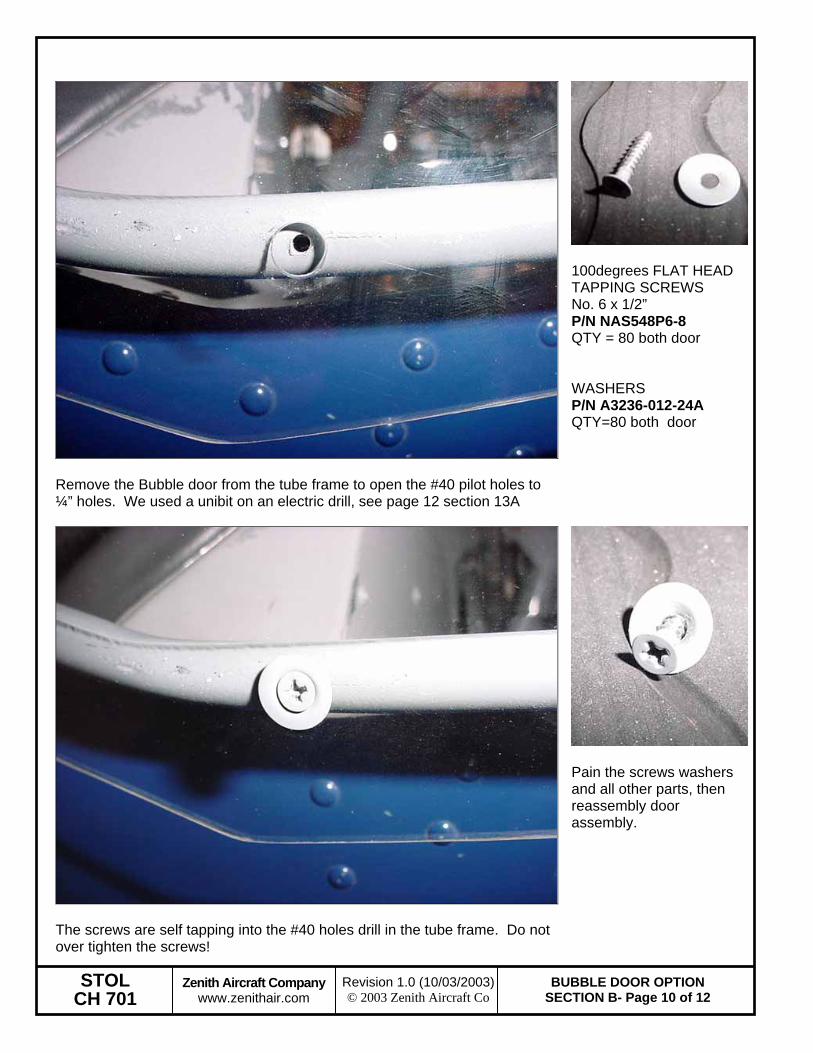
100degrees FLAT HEAD TAPPING SCREWS No. 6 x 1/2” P/N NAS548P6-8 QTY = 80 both door WASHERS P/N A3236-012-24A QTY=80 both door
The screws are self tapping into the #40 holes drill in the tube frame. Do not over tighten the screws!
Pain the screws washers and all other parts, then reassembly door assembly.

STOL CH 701
Zenith Aircraft Company www.zenithair.com
BUBBLE DOOR OPTION SECTION B- Page 11 of 12
Revision 1.0 (10/03/2003)© 2003 Zenith Aircraft Co
Suction Cup Assembly P/N 7-SC Drill a 1/4” hole in the middle portion of the bracket, cut a slot to the edge to insert suction cut.
Rivet a retainer strip with 2 RIVETS A4
Installed by drilling out 2 existing rivets in the first rear rib. First rivet approximately 200mm back from spar rivet line. 2 RIVETS A4
CAUTION: DO NOT OPEN THE DOOR DURING FLIGHT. Check that the doors are latched closed before flight.
Suction cup on bottom of wing to hold door open. Bubble door in the open position. Simply pull along the bottom of the door to break the suction. Larger suction cups are available if the door does not want to stay open during taxing and engine run up.

STOL CH 701
Zenith Aircraft Company www.zenithair.com
BUBBLE DOOR OPTION SECTION B- Page 12 of 12
Revision 1.0 (10/03/2003)© 2003 Zenith Aircraft Co
Inside view of left vent as seen from inside the aircraft. The doors are supplied with a pre-cut for the 3-1/4” SNAP VENTS P/N CC3251 If necessary debur the edge of the hole with fine sand paper, check there are sharp edge around the door.
Front view of right side.
Note: for additional ventilation the back flange can be trimmed down parallel to the window (with the vent in the open position).
Modified vent