Embed Size (px)
Citation preview

Theory of Operations


SECTION IPRINCIPLES OF FLIGHT
The helicopter differs from the fixed-wingaircraft in that its lifting surfaces rotate.This allows the surfaces to move to generate liftwhile the helicopter remains Stationary. In theChinook, lift and propulsion are derived from twosets of three rotor blades. Each set of blades ismounted on a rotor head: one forward and the otheraft. Since these heads rotate in oppositedirections, torque is canceled, and anti-torquerotor is required.
In forward flight dissymmetry of lift is caused bythe relative wind, which acts as a head wind onthe advancing blade and increases the lift, whileit acts as a tail wind on a retreating blade anddecreases the lift. The blade cycle shown belowillustrates how the rotor system maintainssymmetric lift through full articulation of theblades.
To equalize lift throughout the cycle, the bladesare permitted to move up and down (flap). Theadvancing blade flaps upward because of increasedlift: the retreating blade flaps downward becauseof decreased lift. The result is a reduction inangle of attack of the advancing blade and anincrease in angle of attack of the retreatingblade. In this way, lift is equalized across therotary-wing disk.
The cycle of a single forward blade withcounterclockwise rotation is illustrated. Thesame cycle occurs with the aft blade, except thatrotation is clockwise, which reverses the 90° and270° positions in the cycle.

Hinge Points
A fully articulated blade assembly is capable ofmovement in three directions about its attachmentto the rotor head. It moves up and down (flaps)around a horizontal hinge pin, fore and aft (leadsand lags) around a vertical hinge pin, and rotates(increases or decreases pitch) by twisting thelaminated tie bars within the pitch-varyinghousing to which the blade assembly is attached.
Lead-lag movements and flapping are caused byexternal aerodynamic forces prevailing in theblades plane of rotation and are beyond the
pilot's control. Pitch changes are controlled bythe pilot, either collectively, to vary the lift,or cyclically, to vary the flight direction.
Control Actions
The Chinook has three basic pilot flight controls:yaw pedals, pitch and roll control stick, andthrust control. The first two controls arepositioned similarly to those in fixed-wingaircraft, while the latter is located to the leftof each pilot's seat. A brief explanation of thehelicopter control actions follows:
Flight control movements are transmitted through asystem of bell cranks and push-pull tubes to amixing unit. Control movements are mixed there tobecome lateral cyclic and collective pitch inputsto the hydraulic actuators in the upper controls.
The upper controls lift and tilt swash plateswhich, in turn, raise or lower pitch links. Thepitch links are connected to pitch-varyinghousings on the blade arms and vary the pitch ofthe blades during the rotation cycle.
Control motions must be coordinated to producevarious flight maneuvers, as in fixed-wingaircraft. In addition, helicopter control actionshave their own characteristic effects on aircraftattitude, and an additional control, the thrustcontrol, must be coordinated for certainmaneuvers. A climbing turn, for instance, isaccomplished by using a combination of directionalpedal, aft control stick, and increased thrust.

Control Stick
For forward flight, the pilot moves the controlstick forward. This increases the thrust of theaft blades and decreases the thrust of the forwardblades, causing the helicopter to rotate nosedownward and move forward as show in theillustration. Since there is a large range oflongitudinal control, a capacity for high forwardspeed and extremes in center-of-gravityaccommodation are inherent.
When the pilot wants the helicopter to movelaterally or to roll to the left or right, hemoves the control stick in the desired direction.This action tilts the plane of rotation of bothsets of rotor blades in the same direction,causing a corresponding movement of thehelicopter.
Thrust Control
Lift can be varied to produce climbs or descentsby changing the thrust of the blades. When thethrust control in the cockpit is raised, the pitchof all six blades is increased simultaneously,causing the helicopter to ascend as shown in theillustration. Lowering the thrust controldecreases the pitch of all six blades, causing thehelicopter to descend. An intermediate setting ofthe thrust control permits a desired altitude tobe maintained.
Auto-rotation (descent without engine power) isaccomplished by lowering the thrust control andmaintaining slight forward motion down to thelanding site. See the following paragraph.

Autorotation
Autorotation is the flight condition in which noengine power is applied and the rotor blades aredriven only by the relative wind. It is used tosafely land a helicopter after engine failure.
In powered flight, airflow over the blades isdownward. During autorotation, the airflowchanges to upward. This upward flow causes theblades to continue rotating but, left unchecked,will also cause the blade angle of attack toincrease to the point where aerodynamic drag willcause a loss of rotor rpm.
To prevent this, on entering autorotation, thecollective control is lowered to decrease bladepitch. This counters the airflow-induced increasein angle of attack and allow lift and rpm to bemaintained. Lift is maintained throughout thehelicopter's descent by balancing collective pitchagainst airflow through the blades until a landingis made.
Overrunning clutches in the drive system allow therotor to turn faster than the engine duringautorotation.
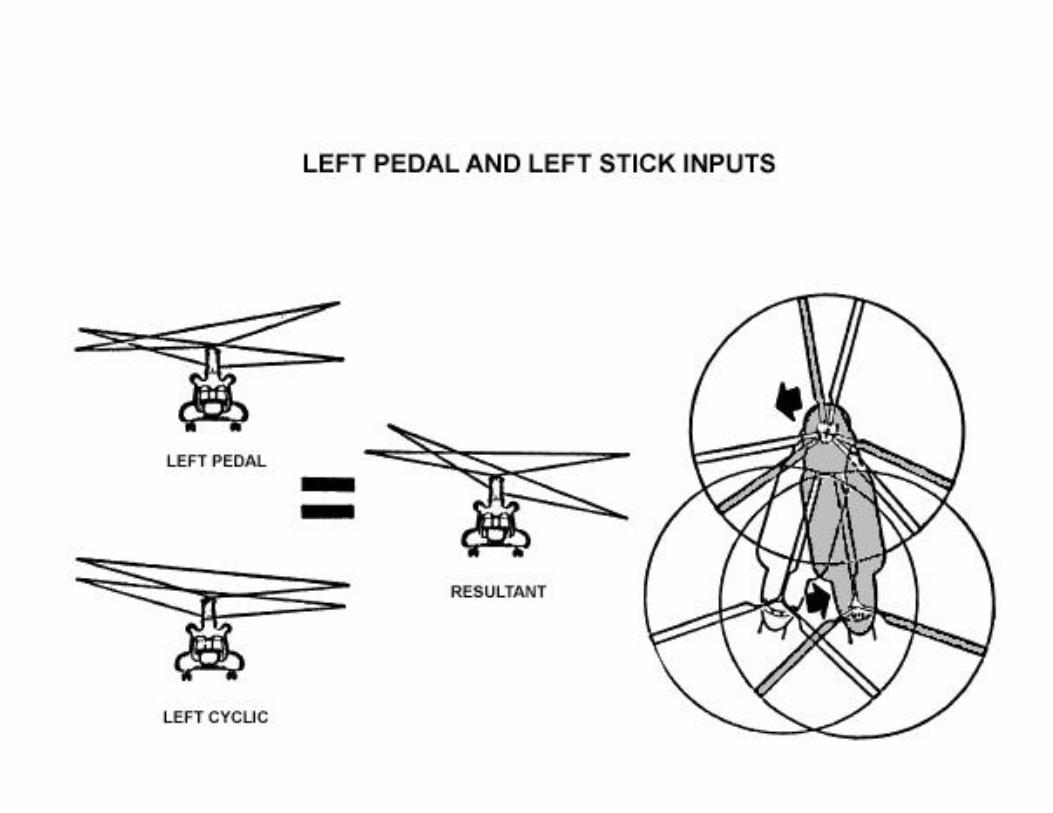
Yaw Control
Yaw is controlled by tilting the plane of rotationof the rotor blades. Control motions toaccomplish this are achieved through the yawpedals.
The plane of rotation is tilted by increasingblade lift through part of the cycle anddecreasing it through another part of the cycle.As the plane tilts, the helicopter moves in thedirection of the downward side of the tilt.
When the pilot applies left or right yaw pedalmovement, the plane of rotation of the forwardrotor blades is tilted in the same direction;simultaneously, the plane of rotation of the aftrotor blades is tilted in the opposite direction.The result is a hovering turn around the verticalaxis. A left pedal application is illustrated.


Automatic Speed Trim
An automatic speed trim system provides longitudinal cyclictilt of the rotor blades proportional to airspeed. Thissystem automatically adjusts the tilt of both sets of rotorblades to provide and essential level fuselage attitude athigh speed. Increasing airspeed also induces programmedremoval of some of the differential collective pitchgenerated through the control stick, thereby providing apositive stick gradient.
If airspeed is constant and the helicopter is momentarilydisplaced longitudinally by gusty winds, causing an airspeedchange, the speed trim system will tend to return thehelicopter to the selected speed.


GLOSSARY
acc accumulator ECL Engine Condition LeverACD Automatic Chart Display EDP Engine Driven Pumpact Actuator EGT Exhaust Gas TempAFT Aft Gearbox EMC Electro-magnetic Transmission CompatibilityAGB Accessory Gearbox Engine Engine Gearboxagb accessory gearbox TransmissionAM Amplitude Modulation Engine Beep Engine RPM Trimant antenna TrimAPU Auxiliary Power Unit FCU Fuel Control Unitaux auxiliary FDIC Flight Displaybcn beacon Interface Controlbfo beat-frequency oscillator FM Frequency modulationBP Booster Pump Fwd Forward Gearboxbrt bright TransmissionBTU British Thermal Unit GSDI Ground Speed DriftCAP Caution Advisory Panel Angle IndicatorCBrF3 bromotrifluoromethane HIGE Hover in ground EffectCCDA Cockpit Controlled Driver HOGE Hover out of ground
Actuator EffectCCS Crew Communication System HSI Horizontal SituationCCT Circuit Indicatorcg or CG Center of Gravity htr heaterCGI Cruise Guide Indicator IFF Identification FriendChip Det Chip Detector or FoeCombining Combining Gearbox ign ignition Transmission ISIS Integral Sparcomp't compartment Inspection Systemcont control LCTA Longitudinal CyclicCP Grip Collective Pitch Grip Trim Actuatorcps cycles per second LCPA Longitudinal CyclicCPT Control Position Transducer Pitch Actuatorcs1 Console LVDT Linear VariableDASH Differential Air Speed Differential
Hold TransducerDCP Differential Collective mkr bcn marker beacon
Pitch mom momentDPFU Dectrac Position Fixing
Unit
1-16

GLOSSARY (Continued)
nac nacelle TACAN Tactical AirN1 Gas Generator Speed NavigationN2 Power Turbine Speed TANS Tactical Airovhd overhead Navigation Systemovsp over-speed Thrust Rod Collective Gripph phase TRU Transformer Rectifierpn1 panel Unitpri primary Transmission Gearboxpsf pounds per square foot wshld windshieldpsi pounds per square inch w/s windscreenPTIT Power Turbine Inlet wt weight
Temperature ut utilityptt press-to-talk util utilitypwr power VAC Volts Alternatingrect rectifier Currentrel release VDC Volts Direct Currentret retract vent ventilateretr retract vgi vertical gyrorf radio frequency indicatorRMI radio magnetic indicator VOR very high frequencysec secondary omni-directionalshp shaft horsepower rangeSIF Selective Identification x-feed
Feature X-Feed Cross-feedsq ft square feet XMSN transmissionSta.. Station ZI Zone IdentificationSta.. No Station NumberSTVA Self Tuning Vibration Absorber
1-17


Introduction
1. The CH-47D helicopter is an improved configuration of the CH-47A, B, and C Model.
2. The objective for the design was to modernize the CH-47 to a configuration to improveoperation, reliability, maintainability, vulnerability/survivability and safety.
3. Structural changes were made to support system changes.
4. Improved system areas are:
a. Fiberglass rotor blades
b. Integrally cooled transmission systems
c. Advanced Flight Control System
d. Improved Avionics/Instrumentation
e. Separated electrical systems
f. Battery charger
g. Multi-Cargo Hook System
h. Improved hydraulic systems
(1) Separate drive for boost pumps
(2) Modular components, permaswage and rusan
(3) Overall reduction of leak points from approximately 1040 in the CH-47C to 220 in the CH-47D.
(4) Addition of a maintenance panel for hydraulic and drive systems.
(5) Improved hydraulic pumps
(6) Improved flight control actuators with jam indicators.
i. T-62T-2B APU with third generator.
j. Oil cooled main generators.
k. T55-L-712 engines.
l. Improved transmissions and lubrication systems.
m. Single-point pressure refueling.
1-18
B. Presentation
1. General Specification Data
a. Empty Weight - approximately 23,000 lbs.
b. Maximum Gross Weight - 50,000 lbs.
c. Engine Rating Limits
(1) Continuous - 3000 HP
(2) Maximum - 3750 HP
(3) Emergency - 4500 HP
d. Fuel Capacity - Total
(1) U.S. Gal. - 1030
(2) Lbs. (JP-4 at 59 degrees F.) - 6693
e. Center-of-gravity-limits TM55-1520-240-20
(1) Std. 310-349 Empty
(2) Std. 310-346 Oper TM55-1520-240-10
(3) Std. 322-331 Max Gross
f. Dimensions - External/Internal
2. Airframe Sections
a. Cockpit
b. Cabin
c. Aft Fuselage
d. Aft Pylon
3. Fuselage Sections
a. The cockpit fuselage is completely fabricated and assembled prior to splicing to the cabin structure.
b. The cabin fuselage is composed of four panels; the crown, left-hand and right-hand side,and bottom. When covered by the cargo floor, the lower section forms a watertightcompartment.
c. The aft fuselage contains the cargo ramp and door is spliced to the cabin fuselage atStation 440.
d. The aft pylon is attached to the aft fuselage structure at field splice. To permittransportation of the helicopter within a limited space, the aft pylon can be removed.
1-19

4. Operating Limitations
a. Cover the following items from Operators Manual, Chapter 5 and Chapter 6.
(1) Rotor
(2) Airspeed
(3) Torque
(4) Cruise Guide
(5) PTIT
(6) N-1 Tach
(7) Engine Oil Pressure
(8) Engine Oil Temperature
(9) Transmission Oil Pressure
(10) Transmission Oil Temperature
(11) Hydraulic Systems
(a) Pressure
(b) Temperature
(12) Center of Gravity
(13) Cargo Hook
(14) Rescue Hoist
(15) Cyclic Trim
(16) AFCS
(17) Landing
(18) Ground Taxiing
(19) Water Operation
(20) APU Operation
(21) Pilot Tube Anti-Ice
1-20

5. Cockpit Arrangement
a. Overhead Panel - Describe function of each panel/switches
(1) Lighting
(a) Pilot's Flt Inst
(b) Anti-Coll Lights
(c) Ctr Sect Inst Lights
(d) Flood Lights
(e) Plt Slt Cont
(f) Dome Lights
(g) Overhead Panel Lights
(h) Console Lights
(i) Co-Plt Cont
(j) Co-Pilot Flt Inst Lights
(k) Formation Lights
(l) Emer Exit Lights
(2) Anti-Ice
(a) Eng
(b) Pitot
(c) Windshield
(3) Hoist
(a) Hoist Master
(b) Hoist In-Out
(c) Cable Cutter
(4) Cargo Hook
(a) Emerg
(b) Select
1-21

(c) Hook Loaded Lights
(d) Master
(5) Hydraulic
(a) Flt
(b) Contr
(c) Pwr XFR No. 2
(d) Pwr XFR No. 1
(e) Ramp
(f) Brake Steer
(6) Fuel Control
(a) Pump Switches (6 ea.)
(b) Aux Press Lights
(c) Cross-feed Fuel Valves
(d) Refuel Station
(7) Start
(a) Switches
(b) Lights
(8) Engine Condition
(a) No. 1
(b) No. 2
(9) Emergency Power
(a) Flag
(b) Timer
(10) Compass
(a) Set Knob
(b) Slave Switch
(c) Indicator
1-22

(11) Troop Warning
(a) Troop Alarm
(b) Troop Jump Lights Switch
(c) Troop Jump Lights
(12) Heating/Windshield Wipers
(a) Windshield Wipers Switch
(b) Vent Blower Switch
(c) Start Switch
(d) Cabin Temp Selector
(13) Electric
(a) APU Switch
(b) BATT Switch
(c) Generator Switches
1 No. 1
2 No. 2
3 APU
b. Pilots Instrument Panel -
Describe each item and its function.
(1) Cruise guide test switch
(2) Cruise guide indicator
(3) Radio call plate
(4) Master caution light
(5) Airspeed indicator
(6) Attitude indicator
(7) AIMS altimeter
(8) Vertical velocity indicator
(9) Radar altimeter display dimmer
1-23

(10) Cockpit air knob turn & slip indicator
(11) Attitude indicator (VGI) switch
(12) Horizontal situation indicator
(13) HSI mode select panel
(14) Radar altimeter
(15) Clock
(16) Rotor tachometer
(17) Torque-meter
(18) Emergency power caution light
c. Copilot's Instrument Panel
(1) Torque-meter
(2) Airspeed indicator
(3) Attitude indicator
(4) Altimeter
(5) Master caution light
(6) Radio call plate
(7) Radar altimeter display dimmer
(8) Vertical velocity indicator
(9) Turn and slip indicator
(10) Attitude indicator (VGI) switch
(11) HSI mode select panel
(12) Horizontal situation indicator
(13) Clock
(14) Radar altimeter
(15) Cockpit air knob
(16) Rotor tachometer
(17) Emergency power caution light
1-24

d. Center Instrument Panel
(1) Missile alert display
(2) Fire control handles
(3) Fire detector test switch
(4) Fire extinguisher agent switch
(5) Gas producer tachometers
(6) Power turbine inlet temperature indicators
(7) Transmission oil pressure indicator
(8) Transmission oil pressure
(9) Longitudinal cyclic trim indicators
(10) Transmission oil temperature selector switch
(11) Fuel flow indicator
(12) Transmission oil temperature selector switch
(13) Fuel quantity indicator
(14) Fuel quantity selector switch
(15) Caution lights and VHF antenna select panel
(16) Engine oil pressure indicators
(17) Engine oil temperature indicators
(18) Master caution panel
(19) KY-28 indicator light
(20) IFF caution light
e. Canted Console
(1) AFCS Panel
(a) System Select Switch
(b) Cyclic Trim Switches
(c) HDG Switch
1-25

(d) BARO Alt Switch
(e) RAD Alt Switch
(f) Stick Position Indicator
f. Flat Console
(1) Emerg Eng Trim Panel
(a) Auto/Manual Switches
(b) Inc/Dec Switches
(2) Steering Control
(a) Swivel Switch
(b) Control Knob
g. Pitch and roll grip
(1) Centering device release switch
(2) Pitch and roll trim control
(3) Inter-phone/radio switch
h. Thrust grip
(1) RPM increase/decrease switches
(2) Search light switches
(3) Thrust control brake trigger
i. Power distribution panels
(1) No. 1 AC and DC
(2) No. 2 AC and DC
6. Compartments
a. Nose compartment
(1) General component locations
(a) Relays
(b) Comm/Nav components
1-26

(c) Hydraulic components
b. L.H. electrical compartment
(1) Electrical external power connection
(2) Component locations inside pod
(a) Electrical power components
(b) Engine control components
c. R.H. electrical compartment
(1) Electrical power components
(2) Engine control components
d. Pressure refueling Station
(1) Panel location
(2) Switch description and functions
(a) Power switch
(b) Panel light switch
(c) Valve test switches (seven (7) each)
(d) Valve lights (two (2) each)
(e) Fuel quantity switch and gage
e. Electronic equipment compartment
(1) Shelf No. 1
(2) Shelf No. 2
(3) Shelf No. 3
(4) Shelf No. 4
(5) Shelf No. 5
f. Heater compartment - identify components
(1) Hydraulic
(2) Heater
(3) Electrical
1-27

7. Maintenance panel
a. Hydraulic indicators
b. Transmitting indicators
c. Engine indicator
8. Emergency equipment/exits
a. Exits
b. First aid kits
c. Fire extinguishers
d. Escape axe
9. Maintenance features
a. Steps and walkways
b. Maintenance platforms
c. Access panels
d. Fuselage drains
e. Overboard drains
f. Air inlet and exhaust openings
10. Protective covers
a. Engine
b. APU
c. Heater
d. Rotor head
e. Nose enclosure
f. Pitot
11. Aircraft physical references
(Stations, Water Lines, and Butt-lines)
a. Stations, water lines, and butt-lines are a method for locating components onthe aircraft. Station numbers are also used as a means for calculating Weightand Balance.
1-28

b. Stations are measured in inches aft from an arbitrary point in space forward ofthe helicopter (21.5 inches).
c. Water lines are also measured in inches and identify vertical locations. Water line "0" is just above the fuel pods. Below "0" is indicated by negative numbers (-)while those above "0" are positive (+).
d. Butt-lines identify right and left locations and are prefixed with "L" for left and "R"for right of the aircraft centerline. Inches are also the unit of measure.
1-29


A. Primary Structural Changes to Support System Improvements
1. Fwd fuselage
a. Reconfigured Fwd Xmsn Support Assy
b. New supports for pallet mounted controls
c. New supports for first and second stage mix units
d. Provisions for wire routing
2. Cabin
a. Modified structure for updated center hook, including new hook beam.
b. Support for new tandem hooks. Crown frame changes for wire routing.
3. Aft fuselage and pylon
a. Pylon changes to accommodate integrally cooled combiner xmsn
b. Changes to Station 534, WL 72 deck, Station 575 and Station 594 frames to providepassage for cooling air to aft xmsn blower
B. Secondary Structural Changes to Support System Changes and Enhance Accessibility
1. Fwd fuselage
a. Hydraulic module and blower spts in fwd pylon fairing and cockpit structure
b. Inlets and exhaust holes for cooling air (xmsn and hyd modules)
c. PDP supports in cockpit
d. Avionics shelf supports
e. Antenna support (IFF, radar-warn, radar alt)
2. Cabin
a. Tandem hook manual release cable and elect connector spts, without 35. MWO isincorporated to include all three hooks in one manual release handle.
b. Misc elect and avionics spts
c. Rescue hatch door change to suit revised hook stowed position
3. Aft fuselage and pylon
a. Pylon L/E fairing change for cooling air inlets (hyd and xmsn)
b. Support struct added to WL 72 deck for hydraulic modules
2-1

c. Supports Added at Upper Thrust Deck for Hyd Exhaust Blowers
d. New Deck Added above APU (Creates Exhaust Air Plenem to T/E of Pylon from AftXmsn Cooler Blower)
e. New Screened Exhaust Hole in T/E and Pylon Crown Fairings
f. Spts for Use of Bomb Hoist for APU Instl or Removal
g. Misc Elect and Hydraulic Component Spts in Aft Fuselage
h. Misc Changes to Formers and Decks to Ensure Adequate Flow of Air to Cooling Units
i. Revised Drainage System in Aft Fuselage
j. Antenna Supports
TEACHING PROCEDURE
C. Cockpit Fuselage Structure
1. Function
a. Section of aircraft which positions and locates pilot and copilot for operation of aircraft.
b. Supplies supporting elements for the subsystems to operate the aircraft.
2. Location
a. Station 21.5 to Station 160.0
3. Nose compartment door
a. Consists of:
(1) Spot-welded aluminum alloy assembly
(2) Hinge
(3) Latch assy
(4) Support strut
(5) Aluminum angles
(6) IFF antenna
4. Control closet structure
a. Location
(1) Station 95 to Station 120
2-2

(2) LBL 8 and LBL 18
b. Function
(1) Location for flight control linkage and controls
c. Construction and specifications
(1) Station 95 canted frame assembly
(a) Upper aluminum forged fitting is one of four fwd xmsn mounting points.
(b) Mounting surface for flight control support pallet assembly.
1 Between WL-10 and WL-16
2 1 1/8 inch thick honeycomb core pallet (145S1645)
3 Attached with (8) fasteners
(c) Sheet metal aluminum web assy siding
(2) Sta. 120 frame assy
(a) Upper aluminum forged fitting is one of four fwd xmsn mounting points.
(b) Mounting surface for flight control support pallet assembly.
1 Between WL-8.5 and -15.75
2 1 1/8 inch thick honeycomb core pallet (145S1646)
3 Attached with (6) fasteners
(c) Sheet metal aluminum web assy
(3) LBL 18 beam assy
(a) Upper aluminum forged fitting is one of four fwd xmsn mounting points.
(b) Sheet metal aluminum web assy siding
(4) LBL 8 siding
(a) Picture frame rectangle open to cockpit entryway
(b) Sealed off by attaching acoustic blanket
2-3

5. Heater closet structure area
a. Location
(1) Station 95 to Station 120
(2) RBL 18 and right-hand outside structure
b. Function
(1) Houses heater assembly
(2) Houses winch assembly
(3) Houses absorber control box
c. Construction
(1) Fwd side is web assy of Station 95 canted frame assembly.
(2) Outboard side is outboard fuselage structure
(3) Inboard boundary is RBL 18 beam assembly.
(a) Upper aluminum forged fitting of beam assembly is one of four fwdxmsn attach points
(4) Aft boundary is the Station 120 frame assembly which leave heater closetarea open to cabin area
Sealed off by attaching acoustic blanket
6. Electronic equipment compartment
a. Location
(1) Station 95 to Station 120
(2) LBL 18 and left-hand fuselage structure
b. Function
(1) Stowing area for electronic control boxes
c. Construction
(1) Fwd boundary is web assembly of Station 95 canted frame assembly
(2) Inboard boundary is web assembly of LBL 18 beam assembly
(3) Outboard side is outboard fuselage structure
2-4

(4) Aft boundary is the Station 120-frame assembly which leaves compartment opento cabin area
(a) Sealed off by attaching acoustic blanket
(5) Compartment contains five shelves
(a) WL-15.50, WL-3.85, WL+6.23, WL+15.12, and WL+24.88
7. Fwd pylon area
a. Hydraulic module support structure
(1) Location
(a) Between Station 150 and Station 120 above cockpit crown trough(tunnel area)
(2) Function
(a) To support hydraulic oil cooler
(b) To support hydraulic system no. 1 hydraulic module
(3) Construction
(a) Made of aluminum alloy angles in a truss formation
(b) Attached to tunnel decking structure and Sta.. 120 frame assembly structure
b. Fwd pylon fairing structure
(1) Location
(a) Top of cockpit structure aft to Station 160
(2) Function
(a) Supply covering for
1 Upper portion of fwd xmsn
2 Fwd upper flight and rotor controls
3 Hydraulic module support structure
(3) Construction
(a) Fixed fairing assembly
1 Fwd section
2-5

a Consists of an inner and outer skin of aluminum alloy and contourmaintained by formers between the skins
b Aluminum tubing from upper area to lower area where hingedfairing meets section
c Aluminum channel follows contour of upper rain-shield to aftsection
2 Aft section
a Skin is made of laminated, plastic-impregnated glass cloth
b Skin is attached to aluminum stiffeners and formers attached toStation 120 frame assy and tunnel decking
c Top area contains a cooling air inlet screen of which approximately2/3 is hinged to provide an access door
(b) Hinged fairing assembly
1 Part of pylon fairing assy as well as serving as a work platform
2 One located on each side of pylon
3 Three fastener locations
4 Construction
a Pre-impregnated glass fabric skin
b Honeycomb core
5 Aluminum support probe is attached to outside surface for support
6 Support 400 pounds
7 Cooling air screen
(c) Spoilers
1 Location
a Two on fwd fixed section of fairing
b One on each hinged fairing assembly
2 Function
a Improve air flow around pylon for improved flight stability
2-6
3 Aluminum pylon cooling air flow
(d) Forward pylon-cooling airflow
D. Cabin fuselage structure
1. Location
a. Station 160 to Station 440
2. Function
a. Section of the aircraft which facilitates cargo handling and troop transportation
3. Specification and construction
a. Cabin framing
(1) Main frames every forty inches in a Station plane to support stringers
(2) Sta. 160 - manufacturing splice
(3) Sta. 440 - manufacturing splice
(4) Constant cross section
(5) Beams, inter-coastal, and stiffeners interspersed for additional strength
(6) Support structure covered with aluminum skin
b. Cabin crown tunnel covers
(1) Function to allow access to drive shafting and supports, hydraulic lines and flightcontrol rods
(2) Six covers located between Sta. 160 and Sta. 440
(a) Numbered (1) through (6) from fwd to aft
(b) Honeycomb material sandwiched between aluminum skin
(3) First, third, and fifth covers have:
(a) Three hinges
(b) Two struts
(c) Hand grip
(d) Three turn lock features
2-7

(e) Sealed overlap
(f) Recessed area for drive shaft flex plates
(4) Second, forth, and sixth covers have
(a) Two hinges
(b) Two turn lock fasteners
(5) First cover contains a formation light
c. Fuel vent-fairing assembly
(1) Location
(a) Three on each side of aircraft common to top of fuel pod structure
(2) Function
(a) Provide cover and screen for fuel vent system
(b) Construction and specification
1 Aluminum sheet metal
2 Stainless steel, 18 gage, wire mesh
3 Attached to A/C structure with four bolts
d. Multiple cargo hook structure
(1) Location of triple hooks
(a) Lower fuselage, Sta. 249, WL 0
(b) Lower fuselage, Sta. 330, WL 0
(c) Lower fuselage, Sta. 409, WL 0
(2) Fwd structure support
(a) Fitting between Sta. 240 - Sta. 260
(3) Center structure support
(a) Fitting between Sta. 320 - Sta. 360
1 Fitting can be rotated for storage under floor boards
(4) Aft structure support
(a) Fitting between Sta. 400 - Sta. 420
2-8

(5) Capacity
(a) Fwd and aft hooks
1 17,000 pounds
(b) Center hook
1 26,000 pounds
e. Rescue hatch lower door
(1) Location
(a) Lower area of center cargo rescue hatch
(2) Function
(a) Seal off lower hatch area
1 Center hook assembly must be stowed or out of aircraft
(3) Construction and specification
(a) Sandwich honeycomb construction
(b) Cutout for hook assembly stowed
(c) Handle for opening door
(d) Latches controlled through latch actuator
(e) Door parallel to floor when open
1 Controlled by linkage
2 Sta. 360 - Sta. 400
(f) Cabin floor access door must be open to open hatch lower door
E. Aft Fuselage Structure
1. Function
a. Supports (4) aluminum ramp hinge fittings
b. Support for attachment of aft pylon
c. Supports fittings for engine mounting
d. Support for aft end of combining xmsn
e. Support aft end of deck at WL48
2-9

f. Supports APU
g. Support structure for aft landing gear
2. Location
a. Sta. 440 to Sta. 630.50
b. Approximately WL-40 to WL+72.0
3. Construction and specification
a. Frame assembly - Station 440
(1) Manufacturing splice
(2) Supports end of tunnel and beginning of combiner drip pan at WL42
(3) Aluminum material
(4) Supports stringers
(5) Supports WL 72 deck structure
b. Frame assembly - Station 482
(1) Aft support for aft end of combiner drip pan at WL 72
(2) Attachment for aft landing gear
(3) Attachment for cargo ramp
(4) Supports WL 72 deck structure
(5) Aluminum material
(6) Supports fwd fitting for engine mounting
c. Frame assembly - Station 534
(1) Supports WL 72 deck structure
(2) Aluminum material
d. Frame assembly - Station 594
(1) Supports WL 72 deck structure
(2) Supports forward mounts for APU
(3) Aluminum material
e. Former assemblies
(1) Location
2-10

(a) Both sides of fuselage structure
(b) Stations 502, 437, 555, and 575
(2) Function
(a) Support for fuselage skin
(b) Support for inter-coastal and beams
(3) Construction
(a) Aluminum material
(b) Opening for Start of plenum structure
Airflow exhaust
f. Tail cone assembly
(1) Location
(a) Sta. 594 - Sta. 630
(b) Ramp enclosure to WL 72
(2) Function
(a) Enclosure for APU
(b) Upper portion contains the plenum for cooling air flow
(3) Construction and specification
(a) Aluminum structure
1 Sheet metal
2 Formers
3 Stiffener
4 Skin
(b) A portion of the bottom liner is fiberglass
(c) Structure ties into
1 Sta. 594 frame assembly
2 Ramp closure structure
(d) Aluminum sheet-metal including deck of WL 72 form a box like structurefor cooler exhaust air.
2-11

g. Engine fairing and cowling
(1) Located as outside cover of engine
(2) Functions as protective housing and streamlined cover for each engine
(3) Construction
(a) Upper cover assy
1 Made of aluminum skin with stringer and formers for stiffening
2 Contains screening for engine cooling
3 Two stepping areas on top
4 Hinged at forward end to fitting on engine
5 Contains support strut
6 Access panels
(b) Side-cover assy
1 Two per engine
2 Made of aluminum material
3 Hinged to upper cover assy in two places and latch to fittings onengine when closed
(c) Lower cover assembly
1 Hinged to fuselage below engine
2 Made of aluminum material
3 Hinges downward
4 Contains screened area for engine coolingF. Aft pylon structure
1. Location
a. Sta. 440 - Sta. 630
b. WL 72.00 and above
2. Function
a. Supports aft xmsn
b. Supports aft vertical shaft
c. Oil cooler support
d. Supports hydraulic modules for boost systems
e. Upper flight control support

3. Construction and specification
a. WL 72 is a field splice for transportability
(1) Drive shaft installed
(2) Drive shaft removed
b. WL 72 deck
(1) Aluminum structure
(a) Webs
(b) Stiffeners
(c) Support brackets
(2) Location of hydraulic module supports
(3) Contains fittings for mounting of aft xmsn
c. WL 90.75 deck
(1) Sta. 502.4-Sta. 575.0
(2) One on each side
(3) Aluminum webs, formers, and stiffeners riveted together
d. Upper canted DECK
(1) Sta. 482-Sta. 594
(2) WL 119 (canted)
(3) Aluminum webs, stiffeners, and formers
(4) Two hole for cooler ducting
(5) Contains fitting for mounting aft rotor drive shaft
e. Structure support former assemblies
(1) Aluminum material
(2) Support pylon structure
(3) Location
(a) Sta. 482, Sta. 534, Sta. 575, Sta. 594
2-13

f. Beam assembly (BL 8.00)
(1) Two beam assemblies
(a) RBL 8.00 and LBL 8.00
(b) Sta. 534-Sta. 575.5
(c) WL 72 to upper canted deck
(2) Function
(a) Main thrust bearing assemblies for aft vertical shaft and aft xmsn
(3) Construction and specifications
(a) Aluminum webs, stiffeners, and fittings
g. Swash plate actuator support beam assembly
(1) Location
(a) Angular beam assembly intersecting former assembly (Sta. 534.0) atLBL 6.369
(b) WL 72.0 deck to canted deck
(2) Function
(a) Load carrying beam for support fitting
(3) Construction and specification
(a) Aluminum webs, stiffeners, and caps
h. Fairings, doors, and access panels
(1) Hinged fairing (work platforms)
(a) Location
1 One located on each side of the aft pylon
2 WL 100-WL 142, Sta. 534-Sta. 575.5
(b) Function
1 Provides a work platform for access to aft upper controls, hydraulicmodules, and drive system items located in aft pylon area.
2-14

(c) Construction and specifications
1 Honeycomb core sandwiched between aluminum skins
a Lower half, inside skin is rigidified aluminum for standing on
2 Substructure and supports are aluminum
3 Latches at
a WL 130.0 Sta. 575
b WL 124.64, Sta. 532.79
4 Two hinges on bottom surface
5 Two-cable assemblies for support
6 Walkway materials is applied to working area of platform
(2) Leading edge hinged fairing
(a) Location
1 Fwd of Sta. 482 above WL 72.0
(b) Function
1 Provide cooling air inlet
2 Protect under structure and provide an air foil
(c) Construction and specifications
1 Honeycomb core covered with fiberglass
2 Hinged at Station 482
3 Two halves with latches on fwd edge at top and bottom
4 Latch release in LH fairing
(3) Forward crown fairing
(a) Location
1 Sta. 481.87 to Sta. 834
2 Above canted deck
2-15

(b) Function
1 Enclosure and protection for pylon structure
2 Provide opening air flow
(c) Construction and specification
1 Aluminum skin with contour maintained by aluminum formers andstiffeners
2 Assembly hinged in the middle
3 LH side permanently attached with screws and a permanent bracestructure
4 RH side contains (5) turn lock fasteners
5 RH side contains a support strut mounted on the inside
6 Both halves contain (2) aluminum screens for cooling system airexhaust
(4) Mid-crown fairing
(a) Location
1 Upper drive shaft enclosure above pylon work platform
(b) Function
1 Provide smooth air foil and protect aft upper control area
(c) Construction
1 Fiberglass skin with aluminum material for formers and stiffeners
(5) Aft crown fairing
(a) Location
1 Between Sta. 575.5 and Sta. 597 above canted bulkhead
(b) Function
1 Provide smooth air foil and protect aft upper control area
(c) Construction
1 Aluminum skin riveted to aluminum stiffeners and formers
2 Top surface is location of anti-collision light
2-16

(6) Trailing edge fairing
(a) Location
1 Sta. 594 to Sta. 627.4 above WL 72
(b) Function
1 Provides trailing edge air foil of pylon
2 Provides mounting for AS-2892/APR-39 antenna, (Radar Detecting)
(c) Construction and specification
1 Upper crown skin is made of fiberglass with fiberglass stiffeners forsupport
2 Bottom portion is aluminum skin supported with aluminum substructure
3 Attached to Sta. 594 former assembly and WL 72 deck assembly
4. Aft pylon air flow
G. Landing Gear Improvements
1. High Flotation Gear
2. Landing Gear Switches (Squat Switches)
H. Self-tuning Absorber Modifications
1. Weight Assembly Change - Tungsten
2. Tuned to 100% rotor RPM (equal 225 rotor RPM)
2-17

CHAPTER 3
ALIGHTING GEAR
LANDING GEAR
DESCRIPTION AND OPERATION
3-1

LANDING GEAR
There are four high-flotation landing gearassemblies, two forward and two aft. The two for-ward assemblies have dual wheels Each aftassembly has a full-swivel single wheel. The aftwheels can be locked in trailng positlon. A powersteering unit is Installed on the aft right landinggear assembly
FORWARD LANDING GEAR
The forward Ianding gear dual wheels are Installedon a fixed axle. The axle IS mounted on an air-oilshock strut bolted to the fuselage support struc-ture. A torque arm keeps the assembly aligned. Adisk and brake unit are provided for each wheel.Hinged panels allow access to the forward landinggear assemblies. Each assembly has a towing andtledown fitting. The wheels can be raised at jack-ing points on the lower torque arms. Left and rightIandlng gear assembles can be converted for usein either forward position.
on bearings in the swivel housing Upper andlower drag links support the swivel housing Both
drag links are connected to fuselage fittlngs Ashock strut IS mounted between the lower draglink and a fuselage fitting, The shock strut has astatic lock mechanism to prevent strut extensionduring helicopter jacking. A disk and brake unit areInstalled on each wheel The aft wheels can befree to swivel, or they can be locked In trailingposition. A centering cam in the swivel housingcenters each wheel in trailing position. A hydrau-lically-operated swivel lock secures the wheel inthis position. The power steering actuator IS con-nected to the aft right Iandlng gear swivel housing,A towing and tiedown fitting is also attached tothis housing Static ground wires are Installed oneach Iandlng gear axle housing. A proxlmityswitch IS mounted on the forward bulkhead ofeach aft Iandlng gear compartment Linkage fromthe upper drag Ilnk IS connected to a target whichis sensed by each switch. The switches areoperated as the helicopter takes off or lands, Ex-tensions on the aft axles are used for connecting a
AFT LANDING GEAR tow bar. An aft landing gear assembly can be ln -
An aft landing gear assembly is Installed on each stalled on either side of the helicopter This re-—side of the fuselage. Each aft wheel IS mounted on quires disassembly and reposltloning of certain
an axle supported by a spindle The spindle rides components.
3-2

LANDING GEAR (Continued)
TIRES AND TUBES
Tires are Interchangeable on all SIX wheels The
tires are 10 ply or 10-ply rating. Tubes are re-
quired for both tubeless and tube-type tires
WHEELS
The wheels consist of two halves. Moisture-proof
seals protect the bearings. Wheels are separated
for removing or mounting tire or tube.
3-3

LANDING GEAR (Continued)
AXLES STATIC GROUND WIRE
Forward and aft axles are removable and can be A static ground wire is installed on the aft leftused on either forward or aft landing gear. Each landing gear. The wire consists of a cable and tubeaxle is secured to the axle housing by a bolt which attached to a mounting bracket. Three holes onpasses thru the axle. the mounting bracket provide for wire length ad-
SHOCK STRUTS
All landing gear shock struts are air-oil units.Compressed air absorbs shock, and hydraulic fluiddampens up and down movements,
justment. The mounting bracket is installed on aclip on the axle housing.
3-4

LANDING GEAR (Continued)
PROXIMITY SWITCHES
Linkage from the aft landing gear upper drag linkis connected to a target. The target is set so theproximity switch IS open when the helicopter is inflight. When the helicopter is on the ground, theswitch is closed. The switches prevent DASH ac-tuator input during lift-off to hover. They alsoreduce AFCS sensitivity 50 percent until lift-off.The right switch turns off the IFF when the heli -copter is on the ground.
STATIC LOCK MECHANISM
The static lock mechanism is a link attached to aftlanding gear shock strut. It is operated by hand tolock the shock strut in the up position when thehelicopter is jacked.
SWIVEL HOUSING ANDSPINDLE
A swivel housing IS supported by the two draglinks and shock strut of each aft landing gear. Thehousing allows the spindle and wheel to swivel360 degrees, A centering cam in the housingcenters the wheel in the trailing position fortaxiing or flight. The swivel locking pin can lockthe wheel in this position.
3-5

LANDING GEAR (Continued)
SWIVEL LOCK DETENTS
Two spring-loaded swivel lock detents aremounted in each spindle. The spring permits thedetent to move down allowing the swivel lockingpin to pass for centering.
3-6

CHAPTER 4
POWERPLANT
POWERPLANT DESCRIPTION
AND OPERATION
4-1

Power Plant System
A. Description
The CH-47D is powered by two T55-L-712 engines. The engines are housed in separate nacellesmounted externally on each side of the aft pylon. The T55-L-712 engine has the capability to produceemergency power on pilot demand.
Each engine has two main sections: a gas producer section and a power turbine section. The gasproducer supplies hot gases to drive the power turbine. It also mechanically drives the engineaccessory gearbox. The power shaft extends coaxially through the gas producer rotor and rotatesindependently of it. The gas producer section and the power turbine section are connected by onlythe hot gases, which pass from one section to the other. During engine Starting, air enters the engineinlet and is compressed as it passes through seven axial stages and one centrifugal stage of thecompressor rotor. The compressed air passes through a diffuser. Some of the air enters thecombustion chamber where it is mixed with star fuel. The mixture is ignited by four igniter plugs.Some of the air is directed to the fuel nozzles. After the engine is started, it continues to operate onmetered fuel supplied to the fuel nozzles. Hot expanding gases leave the combustion chamber anddrive a two-stage gas producer turbine. Energy from the combustion gases also drives the two-stagepower turbine, which drives the power turbine shaft to the engine transmission. The enginelubrication system has an integral oil tank, which is inside the air inlet housing and is serviced with 14quarts.
B. Introduction
1. The CH-47D is powered by two power plant assemblies, designated as No. 1 (left) and No. 2(right).
2. Each power plant assembly consists of an engine and subsystems, for Starting; operating,monitoring, and protecting the engine, as follows:
a. Avco Lycoming T55-L-712 Engine
b. Air Induction System
c. Nacelle Cowling (Cooling) System
d. Exhaust System
e. Engine Mount System
f. Fuel System
g. Lubrication System
h. Start System
i. Engine Control System
j. Electrical System
k. Fire Detection System
4-2

l. Fire Extinguishing System
m. Indicating Systems
n. Maintenance and Operation
3. Each assembly is identical except for right and left installation requirements.
4. Each assembly is demountable to facilitate off aircraft buildup and to provide a quick-changecapability.
C. Location and Access
1. A power plant assembly is located on either side of the aft pylon, centered on butt lines 48 rightand left and waterline 66, and extending from Station 450 to Station 552.
2. The power plant assemblies are structurally attached to the top of the aft fuselage.
3. Each engine is secured by three mounts; two forward at Station 482 and one aft at Station 502.
4. A drag link provides diagonal stability between the forward outboard mount and the aft mount.
5. Normal access for maintenance is gained through hinged access doors on either side of theengine covers.
6. A walkway is provided between the power plant assemblies and the aft pylon for access to theinboard and upper engine areas.
7. A hinged, stowable work platform is provided below each power plant assembly (as part of thefuel pod fairing) to open the outboard hinged side panels and the lower panel for access to theoutboard and lower engine areas.
8. Steps and handholds are provided just forward of the work platforms for access to the top ofthe fuselage (right side) or to the open work platform (both sides).
9. The air inlet bypass screens are removable for access to the engine air inlet and enginetransmission fairing. The screens do not have to be removed to open the upper cover.
10. The engine transmission fairing has hinged panels for access to the engine drive shaftcouplings and lubrication system. The fairings are quickly removable for engine transmissionremoval.
11. Maintenance, removal, replacement, or "quick-change" of either engine is facilitated by thelocation of the nacelles, the design of the engine mounts, and the use of quick-disconnectcouplings on specified lines which lead to the primary structure.
4-3

D. Summary of Leading Particulars
1. Model
a. Military T55-L-712
2. Type
a. Gas producer turbine Two-stage
b. Free power turbine Two-stage
3. Dimensions
a. Overall length 48.53 inches
b. Nominal diameter 28.72 inches
4. Weight
a. Specification weight (dry) 750 pounds
5. Rotational Directions
a. Compressor rotor Counterclockwise
(1) First stage turbine rotor assembly Counterclockwise
(2) Second stage turbine rotor assembly Counterclockwise
b. Power output shaft Clockwise
c. Power turbine shaft Clockwise
(1) Third stage turbine rotor assembly Clockwise
(2) Fourth stage turbine rotor assembly Clockwise
6. Type fuel
a. Army standard MIL-T-5624(Grade JP-8)
b. Alternate MIL-T-5624(Grade JP-5)MIL-T-83133(Grade JP-8)
7. Type oil MIL-L-23699 orMIL-L-7808
4-4

8. Miscellaneous
a. Combustion chamber External annular
b. Compressor ratio 8 to 1 minimum
c. Guaranteed minimum altitude 25,000 feet
D. T55-L-712 Engine Specific Ratings (See Table 1)
1. All T55 series engines are designed to develop a minimum 3750 SHP with a gas producerturbine inlet temperature of approximately 1875°F and a specific fuel consumption of 0.525 witha minimum airflow rate of 28.2 lbs./sec.
2. The -712 series engines are rated for an emergency power of 4500 SHP for a 30-minutecumulative time, with the following conditions: max. T4 of 2050°F, mas. T4-5 of 1670°F, a max.fuel flow of 2340 lbs. per hour, and a max. airflow rate of 30 pps.
E. CH-47D Helicopter Operational Ratings (See Table 2)
1. Operational ratings and limits result from the power train and rotor systems when the enginesare installed on the helicopter.
2. These ratings and limits are monitored and controlled from the cockpit.
F. Dimensional Data
1. Overall length
a. Basic engine 48 inches
b. Basic engine with engine transmissionand fairing installed 71 inches
c. Basic engine with exhaust cone installed 79 inches
d. Basic engine with engine transmission,exhaust cone, and fairing installed 102 inches
2. Overall diameter
a. Basic engine 28 1/4 inches
b. Basic engine with air inlet fairinginstalled 31 inches
c. Basic engine with air inlet fairingand air inlet bypass screen installed 43 inches
G. Center of Gravity (CG) Data
1. Center of gravity locations are measured from the centerline of the forward engine mounts(Station 482).
4-5

a. 14.3 inches aft (Station 496.3) - engine transmission and fairing installed.
b. 19.0 inches aft (Station 501.0) - engine transmission and fairing removed.
H. Weight Data
1. Specification dry weight, as received from the manufacturer. 750 lbs.
2. Built up weight, ready for installation, without engine transmission and enginetransmission fairing. 904 lbs.
3. Built up weight, ready for installation, including engine transmission and enginetransmission fairing, less air inlet bypass screen (16 pounds). 1041 lbs.
I. Terms and Abbreviations
1. GI Ground Idle - The lowest self-sustaining powersetting
2. 40% MAX CONT. Low Idle Power setting
3. 75% MAX CONT. High Idle Power setting
4. MAX CONT. Maximum power setting for continuous engineoperation
5. INT. High Power setting, 30-minute duration
6. MAX Maximum Rated Power, Top power setting for a10-minute duration
7. EMER Highest Power setting, 30 minute cumulative time
8. P Pressure - Absolute - PSIA
9. T Temperature - Absolute - °C A/C - °P Test Cell
10. SFC Specific Fuel Consumption - LB/hr/shaft horsepower
11. SHP Shaft Horsepower - Power output of the engine
12. Wa Airflow Rate - lb./sec
13. Wf Fuel Flow Rate - lb./hr
14. MGT Measured Gas Temperature - °C - °F
15. NR Aircraft Rotor Speed - % of RPM
4-6

16. NG (N1) N = Speed, G = System (GP) Gas Producer = % of RPM
17. NP (N2) N = Speed, P = System (NP) Power Turbine = % of RPM
J. T55-L-712 Engine Difference and Improvements
1. Emergency power rating of 4500 SHP for 30 min. cumulative time.
2. Fixed inlet guide vanes, elimination of actuator.
3. Sealed output shaft with improved lubrication to No. 1 main bearings.
4. Improved vane cooling to 1st and 2nd stage gas producer nozzles.
5. Improved retention to gas producer turbine wheels and spacer assembly.
6. Improved gas producer turbine wheel cooling.
7. Improved 3rd stage nozzle airflow and cooling characteristics.
8. Main oil filter with bypass indicator button.
9. Air-blast atomizing fuel injector nozzles.
10. Barrier fuel filter with throw away filter.
11. Improved inline fuel filter with bypass indicator.
12. Flow divider changes to accommodate swirl cups and air-blast fuel injectors.
13. MGT changes to 5 dual probe segments and bus bars for ease of troubleshooting andreplacement.
K. Engine Construction and Description
1. All AVCO Lycoming T55 series engines are direct-drive shaft turbine engines, incorporating atwo-stage free power turbine section, a combination axial-centrifugal compressor driven by atwo-stage gas producer turbine section and fitted with an external annular atomizingcombustor.
2. The engine consists of:
a. An air inlet section
b. A gas producer compressor section
c. Accessory drive gearbox
d. Air diffuser section
e. Gas producer turbine section
f. The combustor turbine section
4-7

3. All sections, except the accessory gearbox, provide an annular flow path for air and hot gases,and are structurally interdependent and support internal rotating systems. Attachingcapabilities are provided for mounting engine required external components and accessories.
4. Air Inlet Housing
a. The air housing is a one-piece magnesium alloy sand casting, integrally constructed asan inner housing, outer air inlet shell, and four hollow connecting struts.
(1) The inner housing contains:
(a) Output shaft and its supporting structure
(b) Compressor rotor forward bearing support structure
(c) Electrical torque-meter head assembly
(d) Oil tank cavity, a 3.75 gallon capacity
b. Four hollow struts connect the outer shell to the inner housing which supports the forwardend of both gas producer and power turbine shaft by supporting No. 1 and No. 3 bearingsrespectively. They serve as oil passages and enclosures for accessory drive shafts.
c. Internally, the inner housing contains the integral oil tank, power output shaft, No. 6 andNo. 7 bearings, output shaft support housing, accessory drive gear carrier, torque-meterhead assembly, and No. 3 bearing support assembly.
d. This assembly is the main support structure for the engine and contains four mountingpads from which the engine may be cantilevered. The front face of the inner casingincludes studs for mounting the engine transmission.
e. Located around the periphery of the inlet housing are:
(1) Four front engine mounts
(2) Accessory gearbox
(3) Torque system junction box
(4) Starter gearbox
(5) Oil tank filter
(6) Forward hoisting points
(7) Temperature sensing ports
(8) Oil level indicator
4-8

5. Compressor Section
a. The compressor section consists of:
(1) An upper and lower housing assembly
(2) Compressor rotor assembly
(3) The No. 1 and No. 2 main bearings
b. The housings are constructed of sand cast magnesium alloy with erosion-resistantstainless steel inserts, which provide a running area for each axial compressor rotor disc.
c. The seven two-piece steel stator assemblies of the axial compressor are bolted to theupper and lower housings.
d. The stator vanes are fixed in position to inner and outer shrouds.
e. The inner shrouds are lined with lead, which when properly fitted, forms an air seal topermit reduced clearance with no resultant danger from rubs against the rotor andspacers.
f. The housings are split axially to permit access to the compressor rotor for inspection andblade or stator rework or replacement.
g. The internal surfaces of the housings are surface treated and coated with epoxy phenolicplus graphite filler. The external areas are treated with epoxy phenolic engine graypigmented paint.
h. A special air gallery with an easily accessible connection is incorporated to permitcustomer use of bleed air.
i. The compressor rotor assembly consists of
(1) A seven-stage all steel axial compressor
(2) A titanium two-piece centrifugal impeller
(3) The No. 1 and No. 2 main bearings
j. The seven-stage axial and single-stage centrifugal compressors are fitted to a shaft toform a single rotating member.
k. The titanium centrifugal compressor is connected by a spline press fit to the compressorshaft.
l. The compressor parts form a rigid drum compressed together on the shaft and heldtogether by a large high torque lock nut.
4-9

6. Air Diffuser Assembly
a. The air diffuser is constructed of stainless steel material located between the compressorhousing and the combustion chamber housing.
b. Straightening vanes are incorporated to eliminate swirl as the air is exhausted from thecentrifugal compressor.
c. The diffuser supports the:
(1) Combustion chamber housing
(2) Gas producer turbine nozzles and cylinder assemblies
(3) Curl assembly
(4) The rear (No. 2 main) compressor rotor bearing housing
7. Combustion Chamber:
a. The stainless steel combustor housing is fastened to the air diffuser with 52 bolts aroundthe outer circumference.
b. The combustion chamber is a reverse-flow external annular type with a fuel atomizingsystem.
c. The folded design permits maximum utilization of space and reduces gas producer(compressor) and power turbine shaft lengths.
d. The atomizing combustor utilizes 28 main fuel-atomizing nozzles of dual orifice design intwo interchangeable dual channel fuel manifolds.
e. Each manifold supplies fuel to 14 main fuel nozzles.
f. Main fuel is supplied to a flow divider, which directs primary fuel through the aft channelin the manifolds.
g. Secondary fuel is metered in accordance with the primary fuel flow by the flow dividerand delivered through the forward channel of the manifold.
h. The perforated combustor liner is manufactured from (Hastalloy X) heat-resistant alloy.
i. The perforations are arranged to meter air into the combustor for combustion andcooling.
j. Fuel is injected directly into the combustor through the atomizing nozzles, which areevenly spaced around the rear of the combustor.
8. Gas Product Turbine Section
a. The gas producer turbine section is a two-stage axial flow air-cooled turbine system.
4-10

b. The two turbines are coupled together and mounted on the rear of the compressor shaftto form a single rotating member. This system consists of the 1st and 2nd turbines andthe 1st and 2nd nozzles.
(1) First Gas Producer Nozzle
(a) The 1st gas producer nozzle contains 55 hollow vanes.
(b) The T55-L-712 series incorporates full slotted trailing edge design vanecooling.
(c) The nozzle is bolted on the inner wall to the air diffuser, and the combustorliner is slip-fitted to the outer wall; also fitted to the nozzle is the turbinecylinder, which is a separate removeable and replaceable part.
(d) On the T55-L-712 series the second nozzle is a two-pass air-cooled nozzlewith epoxied trailing edge holes for vane cooling.
(e) The 2nd nozzles are bolted to the first nozzle and provide a seat for the 3rdnozzle seal rings.
(2) First Gas Producer Turbines
(a) The first gas producer turbine is splined to the compressor shaft and held inplace by a single high torque lock nut.
(b) The turbine disc is fitted with base shrouded, ball-root, three-pass air-cooledblades held in place by a cooling disc on the front side and a sealing ring onthe rear.
(3) Second Gas Producer Turbine
(a) The second gas producer turbine is bolted to the first turbine and fitted withtwo-pass air-cooled, base shrouded, ball-root blades.
(b) The blades are retained axially to the disc with pins.
(c) The area between the blade base shroud and the disc is sealed with a sheetmetal sealing plate.
(d) The axial relation of these two turbines is fixed by a spacer.
9. Power Turbine Assembly
a. The power turbine (PT) is a two-stage axial flow turbine system coupled together andsupported on the rear by a dual set (No. 4 and No. 5) of main bearings which are locatedin the fourth PT nozzle and on the front end by the No. 3 main bearing.
4-11

b. The turbine rotor assembly includes the third and fourth Stage steel turbine discs both ofwhich are fitted with steel, tip shrouded, ball-root blades fixed in place with steel pins.
c. The third PT turbine rotor consists of four major parts:
(1) The forward spline
(2) Power turbine shaft
(3) Third power turbine disc
(4) The stub shaft
d. These four parts are inertia welded to form one rotating member.
e. The third power turbine nozzle houses the five sets of MGT probes, whose harnesspasses through a tube located on the fourth PT nozzle.
f. The fourth power turbine is splined and held fast to the shaft by a special high torquelock nut.
g. The AVCO Lycoming T55 series shaft turbine engines have two major functionalsystems. A gas producer N1 (NG) system and a power turbine N2 (NP) system. Thesesystems are mechanically independent of each other; however, they are both controlledby a single hydro-mechanical fuel/power regulator.
h. Basically, the function of the gas producer is similar to that of a straight jet engine, in thatit produces hot pressurized gases (thermal energy).
i. The power turbine system extracts the thermal energy from the gas producer system anddelivers mechanical power to the output shaft.
10. Engine Main Bearing Identification
a. Number One Bearing:
(1) A ball bearing, supporting the fwd end of the compressor assembly.
b. Number Two Bearing:
(1) A roller bearing, supporting the aft end of the compressor assembly.
c. Number Three Bearing:
(1) A roller bearing supporting the fwd end of the power turbine shaft.
d. Number Four (fwd) and Five (aft) Bearings:
(1) Two ball bearings between third and fourth turbine discs supporting the aft end ofthe power turbine shaft.
4-12

e. Number Six (fwd) and Seven (aft) Bearings:
(1) Two ball bearings supporting the forward end of the power output shaft.
11. Accessory Gear-case
a. The accessory gear-case housing is sand cast from magnesium alloy and mounted onthe air inlet housing at the 6 o'clock position.
b. It contains a vertical power shaft (driven by the compressor rotor shaft) and thenecessary gears, shafts, bearings, mounting pads, and studs for the engine drivenaccessories.
c. Accessories driven by the gear-case are:
(1) Fuel control and power turbine speed governor
(2) Engine oil pump
(3) Gas Producer (N1) tachometer generator
(4) Fuel boost pump
(5) Power turbine (N2) tachometer generator (when used).
d. The accessory gearbox also houses the main oil filter and magnetic chip detector.
L. Engine Operation during Start Cycle
1. The engine is started by energizing the starter with utility hydraulic pressure, starting fuelsolenoid valve, and ignition system. During this operation, the N1 lever is set at GROUNDIDLE.
2. Air enters the inlet housing assembly and into the compressor section. The air is compressedby the seven-stage axial-compressor rotor assembly and the centrifugal compressor impeller.The compressed air flows through the diffuser housing assembly and into the combustionchamber assembly where a portion of the air mixes with the fuel from the starting and/or mainfuel nozzles to form a combustible mixture.
3. Starting fuel flows into the combustion chamber through two Starting nozzles, located at 6- and9-o'clock positions. It is ignited by four equally spaced spark plugs.
4. Combustion occurs and the expanding gases are discharged through the turbine rotor andexhausted through the fourth turbine assembly. Energy is extracted from the gases by twoseparate and independent turbine rotors (gas producer and power turbine). The gas producerturbine rotors drive the compressor rotor assembly, which compresses the air. The powerturbine rotors supply the driving force through the power turbine shaft to the power output shaft.
4-13

5. Approximately two-thirds of the gas energy passing from the combustion chamber is extractedto drive the compressor rotor; the remaining energy is extracted by the third and fourth turbinerotors to drive the power turbine shaft.
6. At 8 to 13 percent N1 speed, the main fuel flows into the combustion chamber via the oil cooler,in-line fuel filter, flow divider and fuel manifold to 28 air blast nozzles where it is ignited by theburning Starting fuel.
7. Compressor rotor speed (N1) increases to the set idle speed as additional fuel mixes withcompressed air and burns. When compressor rotor speed increases to idle speed, the Starter,Starting fuel solenoid valve, and ignition systems should be de-energized.
8. Combustion gases pass through the gas product, turbine nozzle assemblies and impinge uponthe blades of the gas producer rotor assemblies; then pass through the power turbine nozzleassemblies and onto the blades of the power turbine rotor assemblies.
9. The power turbine rotor assemblies are mechanically connected to the power turbine shaft.The power turbine shaft is splined directly into the power output shaft.
10. Exhaust gases are expelled through the fourth turbine nozzle, fourth stage power turbine rotorblades and exit vane assembly into the atmosphere.
4-14

1. Description
a. Fuel System
The engine fuel system consists of the fuel boost pump and barrier fuel filter, the fuelcontrol unit, the start fuel solenoid valve, inline fuel filter, flow divider dump valve, thestarting and main fuel manifolds, the igniter nozzles, and the combustion chambervaporizers. The system delivers atomized starting and main fuel to the combustionchamber. A pressure-closed drain valve, located at the bottom of the combustionchamber housing, automatically opens and allows unburned fuel to drain from thecombustion chamber following a false start or when the engine is shutdown.
b. Fuel Control
The fuel control unit is a hydro-mechanical device containing a fuel pump section, gasproducer, and power turbine speed governors, an acceleration and deceleration control,an air-bleed signal mechanism, and a fuel shutoff valve.
Functionally, the fuel control unit is divided into the flow control section and the computersection. The flow control section consists of the components that meters engine fuelflow. The computer section comprises elements that schedule the positioning of themetering valve of the flow control section as a function of the input signals to the fuelcontrol unit.
2. Starting Fuel Flow
a. Engine Boost Pump (Driven From AGE)
The engine fuel boost pump is located on the rear right-hand surface of the AGBassembly, adjacent to the main oil pump. It is used with the barrier fuel filter to provide apressure head to the fuel control.
b. Barrier Fuel Filter
(1) Location - the barrier fuel filter is located on the LH side of the engine, directlyabove the start fuel solenoid valve.
(2) Function - filters the fuel prior to the fuel control assembly.
(3) Specifications
(a) Consists of three (3) principle subassemblies
1 The bowl
2 The head
4-15

3 The filter element
4 Impending bypass indicator
(4) The fuel from the boost pump is passed through a quilted paper filter that removes96 percent of all particles larger than 5 microns. There is a valve incorporated inthe filter housing that bypasses the filter element if clogged. The valve opens at5.5 +0.25 psid and is sufficiently large to allow a flow of 1800 pph with a pressuredrop of less than 6.5 psi. The filter housing also incorporates an impending bypassindicator that senses the pressure both upstream and downstream of the filterelement. At a pressure drop of 3.6 +36 psi, the indicator signals an impendingbypass condition via a pop-out button.
(5) Barrier Filter Indicator
(a) The filter pressure drop indicator is a pop-up type indicator that mountsdirectly to the filter housing on the pad previously used for an electricalpressure-drop switch. The pressure port at this location provides actualfilter-element "in" and "out" pressures so that a true filter-element pressuredrop is obtained. The actuating pressure for this unit is 3.6 +0.36 psid.
(b) The pressure-drop indicator consists of two major components.
1 One part is the actuator assembly which consists of a spring-loadedpop-up button and a magnet.
2 The other part is the diaphragm assembly whose main parts are adiaphragm, spring, and magnet
(c) The only dynamic interface between these two components is the forcebetween the two magnets. As filter-element pressure drops below the trippoint, the force of the magnet in the diaphragm assembly keeps theindicator magnet in its standby position. When the pressure differenceacross the diaphragm exceeds its restraining spring force, the magnetmoves away from the indicator magnet. When the resultant magnetic forcesbetween the two magnets become less than the indicator spring, this springforces the indicator to its activated position. Once activated, the indicatorwill stay in its activated position until reset by hand. A guard is providedover the indicator button so that it cannot be inadvertently reset.
c. Starting Fuel Solenoid Valve
The electronically operated, normally closed starting fuel solenoid valve is located on thecompressor housing in the 9 o'clock position. The solenoid valve is actuated by a cockpitmounted switch, which energizes the valve and allows fuel to flow from the fuel controlunit through the starting manifold and to the starting fuel nozzles.
4-16

d. Starting Fuel Manifold and Nozzles
There are two Starting fuel nozzles connected to the starting fuel manifold atapproximately the 3 and 9 o'clock positions. Starting fuel passes through these nozzlesinto the combustion chamber where it is ignited by a spark from an igniter adjacent toeach Starting fuel nozzle.
3. Main Fuel Flow
a. Main Fuel Shut-off Valve (HP Cock)
The HP cock has three functions; to cut off the fuel from the FCU, to prevent fuel passingto the burners until adequate pressure has built up and to provide a bypass circuit withinthe FCU when the engine is wind-milling after fuel is cut off. A mechanical input comesfrom the ECL servo; with the ECL at STOP, the bypass is opened and fuel servopressure closes the HP cock; with the ECL at GROUND the bypass is closed, but the HPcock remains held closed by a spring until main fuel pressure has built up sufficiently.
b. In-line Fuel Filter
(1) The final fuel filtering before the flow divider takes place in the in-line filterassembly.
(2) The filter element has a 7-micron absolute filtering ability.
(3) The assembly incorporates a bypass valve, which will go into the relieving positionwhen 20 to 34 psi pressure drop is encountered.
(4) Maximum pressure drop across the assembly is 4 psi under normal conditions at1500 pph fuel flow.
(5) An impending bypass visual pop-out button is incorporated in the bottom of thefilter assembly for visual inspection of filter.
c. Left and Right Fuel Manifolds
(1) Two manifolds are positioned on the rear surface of the combustion chamberassembly.
(2) Each is supplied secondary and primary fuel through two hose assemblies from theflow divider. Each manifold assembly incorporates 14 dual orifice (air-blast type)fuel nozzles.
(3) Each nozzle delivers fuel to the combustion chamber through a primary (pilot) floworifice and a secondary (air blast) flow orifice.
4-17

d. Air Blast Injector Nozzles and Swirl Cups - the 28 air blast injector nozzles function isdependent upon the flow divider, the dual channel manifold, and the 28 air blast swirlcups.
(1) Operation
After metered main fuel leaves the fuel control, it passes through a fuel/oil heatexchanger (cooler) mounted on the right side of the engine. The cooler uses fuelto cool the oil. Fuel flows from the cooler to an inline fuel filter and then to a flowdivider. The flow divider provides primary and secondary fuel flow to a dual-passage fuel manifold, incorporating 28 dual orifice atomizing fuel nozzles forintroducing fuel into the combustor. The fuel nozzles are air-blast type.
In the flow divider assembly, this fuel is directed through the flow divider piston tothe main fuel pilot channel of the main manifold, fuel is then directed to the 28-injector nozzles. Fuel enters the center pilot channel of the nozzle and passesinternally to the swirl chamber, the fuel is then sprayed out through the pilot orificeinto the combustor at a predetermined angle.
To atomize this fuel, combustor air blast air is introduced into the injector nozzlethrough drilled passages where it flows internally to the pilot swirl chamber outerhousing. The air is imparted upward and out into the combustor where it mixeswith and atomizes the fuel to a fine spray fuel pattern. Associated with the four air-blast passages there are also eight secondary air-blast drilled air channels in theinjector nozzle. Combustor air pressure enters the nozzle through the eightpassages and flows internally to a series of swirl slots where it is swirled aroundthe fuel forming the flame pattern and providing additional atomization. Fuel isintroduced in the outer rear orifices of the nozzles where it flows forward throughthe secondary channel to the inner casing of the nozzle tip. At this point the fuelwould serve no significant purpose without air blast air as in pilot fuel flow. Air blastair enters the four drilled passages. While fuel is being forced down into the airblast channels, air pressure is contacting the fuel and "blasting" it out into thecombustor at as a fine fuel spray.
The secondary air blast air passes through the eight drilled passages into the swirlslots and mixes with the fuel to provide flame pattern and further atomize the fuel toa state where the mixture becomes a film of fuel. Another component associatedwith the air blast system is the swirl cup, which serves a dual function. The injectornozzle is placed in the center of the swirl cup so that it divides the air holes. As airpasses through the series of holes of the swirl cup, half of the flow contacts thenozzles and is deflected up the forward face of the cup, thereby preventing carbonbuild up, and the remaining air contacts the secondary air blast fuel that is beingthrown outward and helps control the flame pattern, thereby preventing it fromcontacting the swirl cup or the combustor liner.
4-18

The combined efforts of pilot fuel flow, secondary air blast fuel flow, and the threemodes of air blast air provide a very high density fuel flow with low fuel pressure,thereby eliminating premature hot end component failure. The air blast systemprovides a more efficient operating engine by providing a more stable combustortemperature.
e. Engine Drain Valves
Pressure-operated engine drain valves are in the bottom of each engine combustionhousing. The valves automatically drain unburned fuel from the combustion chamberfollowing a false Start or whenever the engine is shut down. One valve is at the forwardend of the combustion chamber and the other is at the aft end to ensure completedrainage.
f. Engine Inter-stage Air Bleed
To aid compressor rotor acceleration and prevent compressor stall, and inter-stage airbleed system is provided on each engine. A series of vent holes through the compressorhousing at the sixth stage vane area allows pressurized air to bleed from the compressorarea. This enables the compressor rotor to quickly attain a pre-selected rpm. Thepneumatic inter-stage air bleed actuator controls operation of the air bleed by tighteningor loosening a metal bank over the vent holes. The inter-stage air bleed system operatedautomatically when the engine condition levers or the engine beep trim switches are usedto govern rpm. Should the bleed band malfunction and remain open, there would be anoticeable loss in power.
g. Fuel Flow System
(1) The aircraft is equipped with a fuel flow indicating system. Its function is to indicateto the pilot and copilot the fuel flow rate in pounds per hour to the aircraft's twoturbo shaft engines. Rate of fuel flow is detected by respective engine fuel flowtransmitters and displayed in the cockpit on one indicator on the center instrumentpanel.
(2) System components
(a) Transmitter - Qty (2)
1 Location
a Station 492, WL +23 left side
b Station 492, WL +23 right side
4-19

2 Description and Data:
a Drives cockpit indicator as a function of fuel flow from tank toengine.
b Transmitter impeller motor receives power from indicator
(b) Indicator
1 Location:
a Cockpit center instrument panel
2 Description and Data:
a Power input - 115 VAC 400 HZ from AC No. 1 bus
b Power input - 115 VAC 400 HZ from AC No. 2 bus
c Indicates fuel flow in pounds per hour
d Graduated from 0-28 (X100) with markers at every 100 PHr point.
(c) Power Supply Unit:
1 Location:
a Station 534 left side in cabin.
2 Description:
a Provides power supply to both transmitter motors.
3 Maintenance
(3) System Operation
(a) The No. 1 and No. 2 engine fuel flow systems are identical
(b) Power to operate each system is routed from the 115-volt ac bus through 5ampere FUEL FLOW circuit breaker to the indicator.
The 115-volt ac from No. 2 bus is applied to the No. 2 power supply circuit.
(c) The fuel flow indicator power supply furnishes power to the transmittermotor, the rotor of which is an impeller. This impeller is driven at a constantangular velocity. As fuel passes through the impeller it attains the angularvelocity of the impeller. The angular momentum of the fuel induced by thisrotation is imparted to a spring-restrained turbine, which causes the turbineto deflect through an angle proportional to the flow-rate. This angulardeflection is converted to an electrical signal by magnets in the turbine andpick-off coil around the turbine. The electrical signal is applied to the fuelflow indicator, thereby indicating the flow-rate.
4-20

(d) Voltage is also applied as a reference voltage to the coil that drives thepointer and the coil that is driven by the transducer turbine. The No. 2power supply provides two stepped dc voltages displayed by 90°. Eachvoltage has a repetition rate of 6 Hertz. These voltages are applied to thewindings of the two-phase motor that drives the impeller at a constantspeed.
(e) The reference voltage in the coil driven by the turbine induces voltages atthe taps. This voltage varies with the position of the turbine. The voltagesare applied to the coil that drives the pointer, and will position the pointer tothe fuel flow as directed by the turbine.
(f) The indicator is illuminated by integral lamps powered from the centerinstrument panel lighting circuit. This circuit provides between 0 and 5-voltdc depending on the setting of CTR SECT INST LTS dimmer control.
4-21

A. Engine Starting System Improvement
1. Single-switch Starting
2. Indicating LTS for Start Motors
3. Start Circuits not Inter-locked with ECL
B. Description
1. Starting System
Each engine is started using hydraulic power from the utility hydraulic system until self-sustaining speed has been achieved. The Start system for each engine includes an ignitionsystem, a hydraulically operated start motor, a start fuel solenoid valve, a START switch, andan ignition logic switch.
2. Ignition System
The ignition system has 4 igniter plugs in the combustion chamber which are energized by acoil assembly supplied from the No. 1 or No. 2 DC bus-bar, as appropriate. An ignition exciterunit converts low voltage DC to the high voltage required at the igniter plugs.
3. System Operation
a. Starting Procedure
When the start switch is moved to MOTOR, the STARTER ON caution light comes onand the start valve opens. The start valve applies utility system pressure from the apu tothe engine starter; rotating the engine starter and compressor. At 10 to 15 percent N1,the engine condition lever is moved to GROUND. The start switch is immediately movedto START, energizing the ignition exciter. Start fuel is sprayed into the combustor andcombustion begins. Prior to ptit reaching 450°C, the START switch is manually releasedto MOTOR. At MOTOR, the Start fuel valve is closed and the ignition exciter is de-energized. The start valve remains open, however, and the starter assists the engineuntil starter cutout speed of 50 percent N1. The engine then accelerates to a ground idlespeed. At 50 percent N1, the START switch is manually moved to the locked OFFposition. At OFF, the pilot valve closes, closing the start valve and de-energizing theSTARTER ON caution light. A relay in each engine start circuit is energized when eitherSTART switch is at MOTOR or START. The relay, when energized, disables the startcircuit of the opposite engine, preventing simultaneous dual engine starts. The start andignition circuits receive power from No. 1 and No. 2 dc buses through the START &TEMP and IGN circuit breakers on the power distribution panels.
4-22

b. Aborting a Starting Cycle
A starting cycle can be aborted at any time by moving the ECL to STOP. If venting run isrequired, the engine is motored over by setting the ECL to STOP and then setting theENG START switch to MOTOR, at which gives 15 to 17% N1.
c. Ignition Lock Switch
An ignition system lock switch is installed on the right side of the console forward of thethrust control. The key-operated switch prevents unauthorized use of the helicopter.When the switch is off, the circuits to the ignition exciters and the start fuel solenoids ofboth engines are open. Therefore, the engines cannot be started. Be sure both STARTswitches are OFF before turning the ignition lock switch ON or OFF.
d. Engine START Switches
Two engine start switches are on the START panel on the overhead switch panel. Theswitches are locked in OFF, detented in motor and spring-loaded from START toMOTOR. At START, the engine is rotated with Start fuel and the ignition circuits areenergized. At MOTOR, the engine is rotated by the starts, but ignition and start fuelcircuits are de-energized. MOTOR is selected during starting, in case of engine fire, or toclear the combustion chamber after a false start.
e. STARTER ON Caution Lights
The STARTER ON caution lights, one for each engine, are on the START panel. Thelights will come on when the associated START switch is moved to MOTOR or START.The light alerts the pilots when the START switch is inadvertently left at MOTOR. Thelights receive 28-volt dc from the No. 1 and No. 2 dc buses through the START & TEMPcircuit breaker on the power distribution panels.
4. Malfunctions - TM 55-1520-240-10 (Emergency Procedures)
C. Introduction
1. The helicopter contains a separate starting and ignition system for each engine.
2. Each system consists of an ignition exciter, four igniter plugs, ignition hardness assembly,engine start switch, caution lights, ignition lock switch relays, and solenoid valves.
3. The ignition exciter converts low voltage DC into pulsating high voltage DC through the use of avibrator and transformer.
4. The ignition lead assembly from the exciter, to a spark splitter that contains high voltage coilscarries the high-tension voltage.
4-23

5. High voltage is then distributed to the four igniter plugs in the engine.
6. Each engine has a hydraulically powered starter motor. Hydraulic pressure to operate thestarter is provided by the utility hydraulic system.
7. Starting fuel is automatically programmed to the engine combustor during the Start cycle.
8. The ignition lock switch is located on the right (pilot's) side of the center console.
9. The engine start switches, start caution lights, engine condition levers, and start and ignitionrelays are located in the overhead console panel, and above the pilot's and copilot's heads.
10. Engine mounted components include the starter motor, Start fuel solenoid, 4 igniter plugs,ignition exciter, and ignition lead assembly.
11. The engine start solenoid valves are part of the utility system hydraulic pressure controlmodule. Starter hydraulic returns are plumbed to the utility hydraulic return control module.Both modules are located overhead in the aft cabin at Station 534, waterline +50, butt-lines 15right and left.
12. The engine main electrical harness connects the engine mounted electrical components to theairframe wiring at the engine quick disconnect shelf, and located immediately below eachengine. Fuel and hydraulic quick disconnects are also located on the same shelf. Thedisconnect shelf is accessible through the nacelle cowling lower cover.
13. The start circuit is interlocked to prevent motoring both engines at the same time.
D. Presentation
1. Components
a. Engine start switches
(1) Location: On the engine start panel mounted on the overhead switch panel; oneper start system.
(2) Function: Provides electrical power to initiate the engine starts cycle.
(3) Specifications: Three-position switch marked OFF, MOTOR, & START.
(4) Operation: Placing the switch in MOTOR or START connects 28 VDC from the No.1 or No. 2 DC bus to other system components required for engine start. It alsoprovides a path for 28 VDC to light the respective motor indicating light.
4-24

b. Engine start relays
(1) Location
(a) 101K1: Engine No. 1 start relay
(b) 101K2: Engine No. 2 start relay
(c0 Cockpit area, one on each side of the overhead panel
(2) Function
(a) 101K1 completes electrical control circuits to the No. 1 engine andinterlocks to prevent starting No. 2 engine.
(b) 101K2 completes the electrical control circuits to the No. 2 engine systemand interlocks to prevent starting No. 1 engine.
c. Igniter fuel solenoid valve
(1) Location: Mounted on the engine, left sides, directly above the fuel control unit.
(2) Function: Controls fuel flow to the start fuel nozzles
(3) Specifications:
(a) Normally closed valve
(b) Requires 28 VDC for operation
(4) Operation
(a) With the start switch in START position, the engine start relay energized,the valve receives 28 VDC from the No. 1 or No. 2 DC bus.
(b) The valve energizes open and programs start fuel to the start fuel nozzles.
(c) When the start switch is positioned to the OFF position, power is removedfrom the valve, it de-energizes closed removing Start fuel.
d. Ignition Unit
(1) Location: On the upper right side of the compressor housing, directly in front of theair-bleed actuator and above the oil cooler.
(2) Function: Supplies high voltage necessary for spark plug operation.
4-25

(3) Specifications: A vibrator transformer within the ignition unit converts low voltageto high voltage. The high voltage ionizes the gap in each igniter plug to produce acombustion-inducting spark.
(4) Operation
(a) During an engine start, the control circuitry connects 28 VDC to the unitthrough the engine start switch.
(b) The high voltage output of the exciter is supplied to the igniter plugs in theengine combustion chamber.
(c) When engine operation is self-sustaining on main fuel, the start switch isplaced to OFF and ignition is removed.
e. Ignition Coil and Cable
(1) Location: Between the ignition unit and the four igniter plugs of each engine.
(2) Function:
(a) The ignition coil and cable assembly transmits high voltage from the ignitionunit to the four igniter plugs in the combustion chamber.
(b) The spark splitter coil, located below the ignition unit, distributes highvoltage to each igniter plug (provides four leads).
f. Igniter Plugs
(1) Location: Four igniter plugs are installed in receptacles in the aft end of thecombustion chamber at approximately the 12-, 3-, 6-, and 9-o'clock positions.
(2) Function: The igniter plugs provide the gap for high voltage to sparks to ignite thefuel mixture in the combustion chamber.
g. Engine Starter
(1) Location: On the starter drive assembly on the engine air inlet housing.
(2) Function: Provide cranking power to the compressor section of the engine duringthe start cycle.
(3) Specifications
(a) The engine starter is a piston-type constant-displacement hydraulic motor.
4-26

(b) Pressure of 3350 psi is delivered to the motor from the utility hydraulicsystem when the engine start valve is operated.
(c) The engine starter hydraulic pressure is supplied the utility system pressurecontrol module which also houses the engine Starter solenoid valves foreach engine. Starter return pressure is plumbed to the utility system returncontrol module.
h. System Operation
(1) The starting and ignition system for each engine is controlled by an ignition lockswitch, a start switch, and the engine Start and ignition relays. The circuits are notrouted through the engine condition control, nor are they dependent on its setting.A key is required to operate the lock switch.
(2) Power for the engine starting and ignition circuit is obtained from the 28-volt No.1DC bus for No. 1 engine and the 28-volt DC No. 2 bus for the No. 2 engine.
(3) Setting the ignition lock switch S7 to ON implements the arming of engine No. 1and No. 2 ignition circuits through contacts C1, C12, and C2, C22 respectively.
(4) Setting the No. 1 engine start switch to the MOTOR detent, power from ENG. No. 1START and TEMP circuit breaker is routed through contacts 5 and 4 of switch S1and the normally closed contacts D2 and D3 of relay K2 to energize relay K1.Contacts 8 and 7 are closed to light the STARTER ON caution light.
(5) With relay K1 energized, engine start solenoid valve 11 is opened and utilityhydraulic system pressure is supplied to the No. 1 engine start motor. Contacts A1and A2 are closed to complete arming of engine No. 1 ignition circuit. Contacts D2and D1 are closed, preventing an inadvertent start of No. 2 engine.
(6) Holding the No. 1 engine start switch S1 in the momentary START positioncompletes the pre-armed ignition circuit through momentary contacts 2 and 1 to theignition exciter, and 11 and 10 to the start fuel solenoid valve. DS1 is alsoenergized to keep the STARTER ON caution light ON.
(7) When engine rpm reaches 10 to 15 percent N1 speed, the No. 1 ENGINECONDITION lever is placed in the GROUND detent position, supplying run fuel tothe engine. The START switch S1 is released to the MOTOR detent position at200° PTIT.
4-27

(8) In this position, the ignition circuit is open allowing the start fuel solenoid valve toclose and the ignition exciter is de-energized. The engine start solenoid valve isheld open to assist engine N1 speed.
(9) At 45 to 50 percent N1 speed, the start switch S1 is placed in the OFF detentposition. The engine combustion is self-sustaining and the start and ignition cyclescompleted.
(10) Engine No. 2 start and ignition circuit is identical in operation, except the normallyclosed contacts D2 and D3 of relay K1 energize relay K2 in the MOTOR andSTART positions of Start switch S2.
4-28

A. Engine Control System Improvements
1. Emergency Power up to 4500 SHP
2. Starting Interlock Removed
3. AFCS Bite Interlock Installed
B. Description
Each engine is controlled by a separate power control system which includes cockpit controls and anengine fuel control unit. Each system provides automatic control of engine gas producer rotor speedand power turbine speed in response to any setting of the engine controls selected by the pilot.Engine gas producer rotor speed (N1) and power turbine speed (N2) are controlled by the fuel controlunit, which varies the amount of fuel delivered to the engine fuel nozzles. During normal operation,the fuel control unit automatically prevents power changes from damaging the engine. Fuel flow isautomatically monitored to compensate for changes in outside air temperature and compressordischarge pressure.
1. Operation
a. Engine Fuel Control Units
Each engine fuel control unit contains a single element fuel pump, a gas producer speedgovernor, a power turbine speed governor, an acceleration-deceleration control, a fuelflow limiter, a fuel control fuel shutoff valve, and a main metering valve. Two levers aremounted on the fuel control unit: a gas producer (N1) lever and a power turbine (N2)lever. Limiting the maximum fuel flow to the gas producer restricts output power of thepower turbine (a function of speed and torque). Maximum gas-producer rotor speed isset by the engine condition levers in the cockpit. The engine condition lever electro-mechanically positions the gas producer lever, which controls the fuel control fuel shutoffvalve and the operating level of the gas producer. During flight, the engine conditionlever is left at FLIGHT position and the output shaft speed is regulated by the powerturbine speed (N2) governor. The power turbine lever is electro-mechanically positionedby the engine beep trim switches, thrust control, and emergency engine trim switches.Output shaft torque is limited by the fuel flow limiter, which limits the maximum fuel flow.The position of the main metering valve is determined by the gas producer speedgovernor, power turbine speed governor, the acceleration-deceleration control, or the fuelflow limiter, depending on engine requirements at that time. The governor or the controlunit demanding the least fuel flow overrides the other in regulating the metering valve.
4-29

b. Speed Governing
The power turbine speed governor senses the speed of the power turbine and regulatesthe amount of fuel, which is supplied to the gas producer. This slows down or speeds upthe gas producer rotor so that power turbine and rotor system speed remains nearlyconstant as loads vary. At minimum rotor blade pitch, the amount of power beingsupplied by either engine is at a minimum. As pitch is increased, more power is requiredfrom the engine to maintain constant rotor speed and power turbine speed (N2) Starts todecrease. The power turbine speed governor senses the decrease of N2 RPM andincreases the flow of fuel to the gas producer. This creates more hot gases for the powersection of the engine. Decreasing pitch causes N2 to increase. The power turbinegovernor senses the increase and reduces the flow of fuel to the gas producer, thusdecreasing the amount of hot gases for the power turbine. The power turbine speedgovernor allows the power turbine output speed to decrease (droop) approximately 10percent when the power loading varies from minimum to full load. A droop eliminatorlinked to the thrust control rod minimizes this. The droop eliminator automaticallychanges the power turbine lever to compensate for droop as pitch is increased ordecreased. Another type of droop, which is only transient, occurs as a result of the timerequired for the engine to respond to changing loads due to N2 governor lag.
c. Engine Condition Levers
Two engine condition levers (ECL), one for each engine, are on the ENGINECONDITION panel on the overhead switch panel. Each lever is used to selectappropriate fuel flow rates for GROUND, FLIGHT, and STOP (engine shutdown).Operation of the ECL moves a position sensor resulting in movement of the N1 actuator.If the N1 actuator fails to align to the position selected by the ECL, or the ECL is not in adetent, the N1 CONT caution light will illuminate. The actuator mechanically operates alever, which controls the fuel control fuel shutoff valve and the operating speed of the gasproducer. The engine condition lever positions are STOP, GROUND, and FLIGHT.Each lever is spring-loaded outboard and is inhibited by lock gates. The ending conditionlever must be at GROUND before the engine will Start. When a condition lever isadvanced from STOP to GROUND, power is then supplied to the electromechanicalactuator, which establishes an appropriate fuel flow rater at ground idle. The speed ofthe gas producer with the lever at GROUND should be 60 to 63 percent N1. When anECL is moved to FLIGHT, the engine is operating within the N2 governing range, unlessthe engine is "topped out" at which time it goes back to N1 governing. The N2 governorthen takes control to maintain selected rotor rpm in response to the engine beep trimswitches and collective pitch changes. When an ECL is moved to STOP, the gasproducer lever closes the fuel control shutoff valve, which stops fuel flow to the gasproducer. The engine condition levers and gas producer actuators allow the pilot toproportionally control acceleration of the gas producer from STOP to FLIGHT. Interlockswitches within the ENGINE CONDITION panel and N1 actuators turn on the N1 CONTcaution light when the N1 actuator position does not agree with ECL position in STOP,GROUND, or FLIGHT. Each electrical system is completely separate and a failure in onesystem will not affect the other. A built-in mechanical brake holds the actuator at its lastselected position if loss of electrical power occurs. ECL friction is provided to reduce thepossibility of over-torquing the engine transmissions by resisting movement of the enginecondition levers. The ECL friction brake cannot be adjusted by the pilot and a force of 4to 5 pounds on the engine condition levers is needed to move them. Electrical power issupplied by the 28-volt dc essential buses through No. 1 and No. 2 COND CONT circuitbreakers on the power distribution panels.
4-30

d. Engine N1 Control Caution Lights
Two engine control caution lights are on the master caution panel. They are marked No.1 ENG N1 CONT and No. 2 ENG N1 CONT. The lights normally come on when theengine condition levers or the N1 actuators are at an intermediate position betweenSTOP, GROUND, or FLIGHT. They go out when ECL and N1 actuator positions agree.However, they remain on if a component of the system (actuator, control box, or conditionpanel) has failed in other than a detent position. The 28-volt dc essential bus supplieselectrical power to the caution lights. A circuit breaker marked CAUTION PNL on the No.1 power distribution panel protects the caution light circuit.
e. Normal Engine Beep Trim Switches
Two momentary switches for engine beep trim are on the auxiliary switch bracket of eachthrust control. Both switches have three positions: RPM INCREASE, RPM DECREASE,and a normal position. One switch, marked No. 1 & 2, is normally used to select desirerotor rpm. Holding the switch forward increases rotor rpm. Holding the switch aftdecreases rotor rpm. When the switch is released, it returns to the center or normalposition. The switch electrically controls both power turbines by movement of the N2actuator through each engine power-turbine control box. The second beep trim switch,marked No. 1 engine. This switch is used to match engine loads, which is indicated bydual torque-meters. Because No. 1 engine beep switch will also change rotor rpm, theprocedure for matching engine load requires that No. 1 & 2-beep switch be used inconjunction with No. 1 engine beep switch. when No. 1 engine beep switch is movedforward (RPM INCREASE), the torque of No. 1 engine increases. At the same time rotorrpm increases, even though No. 1 engine torque decreases slightly. Moving No. 1 & 2-engine beep trim switch aft (RPM DECREASE) causes both engine torques to decreaseand reduce rotor rpm. If torque is still not matched, this procedure is continued untiltorque is matched and desired rotor rpm is attained. The opposite action occurs whenNo. 1 engine beep switch is moved aft. The engine beep trim switches should not beused during power changes initiated by thrust rod movement because rotor rpm droopshould only be momentary. The engine beep trim system adjusts engine rpm only if therespective engine condition lever is at FLIGHT. At STOP and GROUND, it is possible tomove the power turbine lever by moving the engine beep trim switches to DECREASE orINCREASE: but in either case, engine rpm will not be affected because then engine isnot operating in the N2 governing range. Power to operate the beep trim system issupplied by the 28-volt dc and the 115-volt ac buses. Power to operate the power turbineactuators is dc voltage. This dc voltage is derived from the 115-volt ac primary bus afterthe ac is transformed and rectified by the engine power turbine control box. AC circuitbreakers are marked ENGINE NO.1 and NO. 2 TRIM & TIMER. DC circuit breakers aremarked ENGINE NO. 1 and NO. 2 TRIM. The circuit breakers are on their respectivepower distribution panels.
NOTE:No two engines provide matched performance withregard to torque, rpm, ptit or fuel flow. With torquematched all other parameters may not be matched.
4-31

f. Normal ENGINE TRIM System Disable Switches
Two guarded switches are on the emergency engine trim panel on the console. Theswitches permit the pilot to disable either of both normal beep trim systems. Thisprevents unwanted signals from the normal beep trim system from interfering with theoperation of the emergency engine trim system. Each switch is marked AUTO andMANUAL. When either switch is at MANUAL, the respective normal beep trim system isdisabled (115-volt ac from the ac bus to the engine power turbine control is interrupted).When the switch is at AUTO (cover down), the normal beep trim system is functional(115-volt ac from the ac bus is reconnected to the associated engine power turbinecontrol box).
g. Emergency Engine Trim Switches
Two momentary switches for emergency engine trim are on the emergency engine trimpanel on the console. Each switch is used to change the power turbine speed of itsrespective engine if the power turbine control box (normal beep trim system)malfunctions. When the normal trip system fails, the droop eliminator also fails tofunction. Each switch has three positions: INC, DECR, and a spring-loaded centerposition. When one of the switches is held at INC, power from the 28-volt dc essentialbus goes directly to the respective power turbine actuator and increases the lever settingand the power turbine speed. When the switch is held at DECR, the lever setting isdecreased, and the power turbine speed is decreased. The emergency engine trimswitches are to be used when the normal beep trim system is disabled. If one of theswitches is used while the respective power turbine control box is functioning normally,the power turbine actuator setting will temporarily change but will return to its originalsetting when the switch is released. Power to operate the emergency engine beep trimswitches and actuators is supplied by the 28-volt essential dc bus through the No. 1 andNo. 2 EMERG ENG TRIM circuit breakers on respective power distribution panel.
CAUTION:Engine response is much faster when rotor rpm is controlled with emergency engine beep
trim system. It is possible to beep the rotor speed below safe operating speed and lowenough to disconnect the generators from the buses. The generators are disconnected at
85% to 82% rotor rpm after a 3 to 7 second time delay.
4-32

2. Emergency Power
a. Emergency Power System
An emergency power system is included with T-55-L-712 engines. With the emergencypower system, increased power is available on pilot demand and is actuated by raisingthe thrust control into the emergency power range. When fuel flow increases to the pointwhere power turbine inlet temperature is 890° to 910°C, the EMERG PWR light will comeon. If temperature is maintained in this range for more than 5 seconds, the emergencypower indicator will display a black-and-white flag, and the emergency power timer willstart. However, the emergency power indicator will continue to display the black-and-white flag. The flag can be reset on the ground only, using a switch in the nosecompartment. Topping stops are stowed on each helicopter. The stops are installed onthe N1 control of each engine for maintenance engine topping checks. The stops providean established fuel flow when topping. When not in use, the stops are stowed on theright side of the console of the pedals.
b. Emergency Power Panel
The emergency power panel is on the overhead switch panel. The panel is labeledEMERGENCY POWER. The panel consists of an emergency power indicator and adigital timer for each engine. The timer counts the minutes that emergency power is inuse.
c. Emergency Power Caution Lights
Two amber press-to-test caution lights labeled EMERG PWR are installed: one light is onthe copilot's instrument panel outboard of the rotor tachometer and torque meter. Theother light is on the pilot's panel inboard of the rotor tachometer and torque meter. Whenon, the lights indicate ptit on one or both of the engines are in the emergency powerrange.
C. Power Turbine Inlet Temperature System
1. PTIT can provide the pilot with a primary indication of an impending emergency situationranging from "Hot Starts" to "Flame Outs".
4-33

2. The PTIT System in the aircraft monitors the temperature of the air as it passes into the thirdpower turbine wheel.
3. There is one complete PTIT System per engine.
4. Each system requires 10 thermocouple type-sensing devices, an indicator, interconnectingwiring, and contingency power indicator panel.
5. Provides circuit supply for over temperature warning. (Contingency Power)
D. Presentation
1. PTIT Components:
a. PTIT Indicator
(1) Location:
(a) Each engine instrument is located on the center instrument panel.
(2) Description of Data
(a) Range 0 degrees to 1200 degrees centigrade
(b) System Limits
1 400°C to 780°C continuous operation
2 810°C maximum for not more than 30 minutes
3 890°C maximum for not more than 10 minutes
4 781°C to 940°C starting, acceleration, and time-limited operation
5 890°C to 930°C emergency pwr (single-engine)
6 940°C maximum, not more than 12 seconds
(c) The operation of the indicator is basically a DC servo type of instrument.
(d) Set point in rear of instrument adjusted for 890 +5 and/or -0 degrees.
b. Thermocouple Harness
(1) Location:
(a) A thermocouple harness is provided with each engine and is mountedcircumferentually to the third turbine nozzle.
4-44

(b) The 10 probes extend through the nozzle outer shroud into the gas pathbetween the third nozzle vanes.
(c) The output leads extend from the harness through an existing guide tubeand forward to the thermocouple bulkhead mounting bracket on thecompressor housing.
(d) Replacement of probes is accomplished with engine removed from aircraft.
(2) Description of Data
(a) The thermocouple harness consists of:
1 An electrical connector
2 Shielded manifold
3 Ten Chromel-Alumel thermocouple probes
(b) The thermocouple harness is not part of the engine main electrical cableassembly because the system used Chromel-Alumel wires.
(3) Operation
(a) The thermocouple is made of two high temperature dissimilar metals(Chromel-Alumel) joined together to form a hot junction.
(b) Heat applied to the thermocouple produces an electron flow (current)through the junction.
(c) The amount of current generated is a function of the temperature of thethermocouple.
1 High Temp = High current (in "MA")
2 Low Temp = Low current (in "MA")
(d) The current from the thermocouple is directed to the indicator for instrumentoperation.
c. Reset Switch
(1) Location
(a) Nose electronic compartment.
(b) Between Station 30 and Station 40, BL 8.69 RH
(2) Description and Data
(a) Once the counter has started the flag also drops
4-35

(b) The flag will stay down after the counter has stopped and temperature isback to normal.
(c) To reset the flag the reset switch for the respective engine must be operated
d. Contingency Power Panel
(1) Location:
(a) Overhead Panel
(2) Description of Data
(a) Consists of:
1 Operates from 28-vdc. Engine Start and temperature circuit breaker.
2 Elapse time indicator (999 minutes).
a Operates from 115-vdc, 400 Hz from eng trim & timer AC breaker.
3 Flag indicator. (Black - normal, striped - tripped)
4 Relay. (5 second time delay)
a Operates from 28-vdc
(b) Flag Indicator:
1 For Black Flag - Red and yellow terminals are energized by 28-vdc
2 For Striped Flag - Blue and yellow terminals are energized by 28-vdc
3 Yellow Terminal - Ground
2. System Operation:
a. Current generated through the thermocouple junction is sensed by the indicator andcauses the meter to deflect.
b. When the pointer indicates more than 890°C, 28-vdc power is sent to the contingencypower panel.
c. When the temperature is exceeded, the light will come on.
d. After 5 seconds at high temperature, the indicator flag will drop and the elapsed timeindicator will start.
(1) Delay allows transients without tripping flag
4-36

e. When the PTIT drops below 890°C, the light will go out and the timer indicator will stop,but the flag will stay down.
f. To reset the flag a switch must be operated in the nose compartment. Can only bereached by personnel on the ground.
g. The time indicator cannot be reset on the aircraft. It must be run through its cycle of 999minutes or 16 hours and 39 minutes.
h. Continuity/Resistance Check of Harness
(1) Disconnect A/C wiring at the engine connector.
(2) Measure resistance between pins A and B with ohmmeter on RX1 setting.
(a) Meter indication should be between 2.3 and 2.5 ohms at 65°F or between2.4 and 2.6 at 110°F.
(3) Measure between any one pin and the harness outer braid with the ohmmeter atRX100.
(a) Resistance shall be 400 ohms minimum.
(b) If limits are not met - check the connector.
1 If resistance is taken from pin A to pin C or pin B to pin C, the meterindication should be between 3.5 and 4.1 ohms depending upontemperature.
4-37

ENGINE SYSTEM -LUBRICATION SYSTEM, FIRE DETECTION
AND EXTINGUISHING SYSTEM, ANDANTI-ICING SYSTEM
A. Lubrication
1. Description
a. Oil Supply System
The oil supply system is an integral part of the engine. The oil tank is part of the air inlethousing. The tank filler neck is on top of the housing. An oil level indicator is on the leftside of the engine inlet housing.
If the oil level decreases to about 2 quarts usable, the corresponding ENG OIL LOWcaution light will come on. Tank capacity 3.7 gallons.
Operational usage of the engine should not be restricted because of excessive oilconsumption, unless the rate will curtail the mission.
b. Engine Oil Temperature Indicator
Two engine oil temperature indicators are on the center section of the instrument panel.Each engine oil temperature indicator is calibrated from -70° to +150°C. A temperatureprobe within the lubrication lines of the engine, before the fuel-oil cooler, is the point atwhich the temperature is sensed. Power to operate resistance-type oil temperaturecircuit is supplied by No. 1 and No. 2 28-volt dc buses through the ENGINE OIL TEMPcircuit breakers on the power distribution panels.
c. Engine Oil Pressure Indicator
An engine oil pressure indicator on the center instrument panel is provided for eachengine. Each indicator relates pressure sensed at No. 2 bearing by an oil pressuretransmitter mounted near the engine. Each engine oil pressure indicator displays apressure range from 0 to 200 psi. Power to operate the engine oil pressure circuit issupplied by the 26-volt ac instrument buses through the ENGINE OIL PRES circuitbreakers on both power distribution panels.
d. Engine Chip Detector Caution Lights
Two ENG CHIP DET caution lights are on the master caution panel. The caution lightsare electrically connected to a chip detector in each engine and engine transmission. If adetector is bridged by metal particles which may indicate impending engine or enginetransmission failure, the corresponding ENG CHIP DET caution light will come on. Also,the associated ENGINE CHIP DETECTOR or TRANSMISSION CHIP DETECTORmagnetic indicator on the maintenance panel will trip.
4-38

e. Engine Oil Level Caution Light
Two engine oil level caution lights, marked NO. 1 ENG OIL LOW and NO. 2 ENG OILLOW, are on the master caution panel. When a caution light comes on, there are about 2quarts of usable oil remaining in the respective engine oil tank. Each low oil level cautionlight is activated by a micro-switch inside the oil quantity indicator. Power to operate theoil level caution lights is supplied by the 28-volt dc essential bus through the CAUTIONPNL circuit breaker on No. 1 power distribution panel.
f. Engine Chip Detectors.
Two caution lights, marked NO. 1 ENG CHIP DET and No. 2 ENG CHIP DET, are on themaster caution panel. The engine accessory section oil sump chip detector is connectedto the corresponding ENG CHIP DET caution light on the master caution panel and to theENGINE CHIP DETECTOR indicators on the maintenance panel.
g. Oil Cooler
The engine oil is cooled by the inlet air flowing around the tank and the liquid to liquidcooler.
4-39

ENGINE SYSTEM
A. Fire Detection and Extinguishing System
1. Description
a. Sensing Wires
Continuous-type sensing elements which are routed around each engine connected to acontrol unit on the airframe.
b. 2 Extinguisher Bottles
Two extinguisher bottles in the aft pylon. The bottles contain monobromotrifloromethane(CDrF3) and are pressurized with nitrogen; each has two discharge valves connected totwo discharge nozzles each engine bay.
c. Fire Control Handles
Two control handles for the engine fire extinguisher system are on the center section ofthe instrument panel. Each handle contains two red warning lights and control switchesthat close the engine fuel shutoff valve and arm the fire extinguishing system circuits.When one of the handles is pulled out, the respective engine fuel shutoff valve is closedand the fire extinguisher agent switch is armed for selection and discharge of either firebottle by selecting either momentary position on the agent discharge switch. Afterdepletion of the charge in the initially selected bottle, the remaining bottle can bedischarged to the same engine compartment by selecting the opposite position on thebottle selector switch. The other fire control handle performs the same function for itsrespective engine compartment. Power is supplied from the 28-volt dc No. 1 and No. 2essential gases through FIRE EXT circuit breakers on the No. 1 and No. 2 powerdistribution panels.
d. Fire Control Handle Warning Lights
Two warning lights are contained in the end of each fire control handle. When an enginecompartment fire occurs on either side, the respective pair of warning lights comes on.Each fire handle is marked FIRE-PULL-FUEL SHUTOFF. Power is supplied for eachpair of lights from the corresponding No. 1 or No. 2 115-volt ac bus through circuitbreakers labeled ENGINE No. 1 and ENGINE No. 2 FIRE DET on the No. 1 and No. 2power distribution panels.
e. Fire Extinguisher Agent Switch
A three-position fire extinguisher agent switch is above the fire control handles on theinstrument panel. The lever-lock momentary switch positions are BOTTLE No. 1, neutraland BOTTLE No. 2. When one of the fire control handles is pulled OUT and the fireextinguisher agent switch is set in BOTTLE No. 1 position, the agent is discharged fromthe No. 1 container into the selected engine compartment. If the switch is set in BOTTLENo. 2 position in the above case, agent from No. 2 container will be discharged into thesame engine compartment. Only two fire extinguisher agent containers are provided. Ifthe agent from both containers is used in combating a fire in one engine compartment,agent will not be available should a fire occur in the other engine compartment.
4-40

f. Fire Detector Test Switch
The fire detector test switch is below the fire extinguisher agent switch on the centersection of the instrument panel and is labeled FIRE DETECTOR-TEST. The two-positiontoggle switch is spring-loaded to FIRE DETECTOR. The switch is used to check theoperation of the fire detection system. When the switch is actuated, relays in both controlunits close and the lights in both fire control handles come on. Power to operate the testcircuit is supplied by the 28-volt dc essential bus through the CAUTION PNL circuitbreaker on the No. 1 power distribution panel.
2. Operation
a. Engine Compartment Fire Extinguisher System
The engine compartment fire extinguisher system enables the pilot or the copilot toextinguish a fire in either engine compartment only. It is not designed to extinguishinternal engine fires. The system consists of two fire control handles, a fire extinguisheragent switch, a fire detector test switch on the instrument panel, and two extinguisheragent containers on the overhead structure at Stations 482 and 502. The containers arepartially filled with monobromotrifloromethane (CB4F3 or CF3BR) and pressurized withnitrogen. The agent in one or both of the containers can be discharged into either enginecompartment. Selection of the compartment is made by pulling the appropriate firecontrol handle. Selection of the container is made by placing the fire extinguisher agentswitch in the appropriate position. Decontamination of the engine is not required whenthe extinguisher has been discharged.
4-41

c. Engine Inlet Screens
An engine inlet screen which maximizes foreign object damage (FOD) is installed oneach engine. The reduction in engine power available with screens installed is negligible.The engine inlet screens have bypass panels. These two panels are on the aft end ofeach screen. Quick release fasteners attach the panels to the screens. They areremoved if the ambient temperature is 4°C or below and there is visible moisture.
4-42

4-43
a. T55-GA-714A ENGINE GENERAL DESCRIPTION (1) Two Allied Signal Model T55-GA-714A gas turbine engines power the aircraft modified by ECP D 218. A derivative of the T55-L-712, and the improved T55-L- 714 used on the MH-47E the engine is configured with a combination seven-stage axial/single-stage centrifugal compressor driven by a two-stage gas producer (GP) (N1 section) turbine. Gas flow is directed through a reverse flow annular atomizing combustor, through the two-stage GP turbine and two-stage free power turbine (PT) (N2 section). The PT shaft is positioned co-axially within the gas producer shaft and directly drives the power output shaft located at the engine compressor inlet. Power output shaft speed is equal to power turbine speed. The engines are attached to either side of the aft fuselage section by a three-point mount system. Engine electrical, fuel, water wash, hydraulic, and drain system components are connected to the airframe at a quick- disconnect (QD) shelf below each engine.Compared to its predecessors, the T55-GA-714A has been improved to provide additional power and reduce the frequency of required engine maintenance. The power growth as well as the maintainability enhancements are a result of improvements to several areas of the engine.

4-44
b. POWERPLANT IMPROVEMENTS: (1) Replacement of the hydromechanical fuel control system with a Full Authority Digital Electronic Control (FADEC) system. (2) Engine lubrication system improvements. (3) The configuration, alteration, and material composition, of the engine compressor, combustion, and turbine assemblies. (4) Removal of the exit guide vane. (5) Improved Magnostrictive Torquemeter system (6) Installed engine water wash system.
(7) Installation of an improved, deflective, tailcone assembly.
T55-GA-714A CHARACTERISTICS Dimensions
Overall Length 46.53 Inches Overall Length (Tailpipe inst.) 77.53 Inches
Nominal Diameter 24.25 Inches Weight
(Less Eng. Transmission and Exhaust Cone) 832 Pounds
Combustion chamber External annular Compression ratio (max) 9.32 to 1
Horsepower (max rated) 4,867 (10 minutes) Emergency 5,069 (2 minutes)
Maximum altitude 25,000 feet Power level N1 100% = 18,720 RPM Power level N2 100% = 15,333 RPM

4-45
.
a. POWERPLANT INSTALLATION (1) Maintenance, removal, and installation of either engine is facilitated by the location of the nacelles, the design of the engine mounts, and the use of quick-disconnect couplings on lines which lead to the aircraft structure. Three mounts secure each engine: two forward and one aft. Access for maintenance is gained through hinged access doors and cowlings on the engine and aircraft structure. Engine total weight, ready for installation (including engine transmission, and exhaust cone) is 1,411 pounds.

4-46
b. Unique T55-GA-714A Engine Installation And Removal Task: (1) The tailcone is clamped and bolted (6 bolts) to the engine turbine assembly. (2) FADEC primary, reversionary, and accessory harnesses. (3) The P3 pressure line to the Digital Electronic Control Unit (DECU).
(4) The water wash system pneumatic and fluid lines.
c. The engine mounts provide a three-point structural support, two forward and one aft, for each engine. The mounts are accessible through the hinged engine cowlings. (1) The aft engine mount is an adjustable link that has replaceable bearings. Each link is adjusted to ensure the proper alignment of the engine drive shaft and combining transmission input adapter. Once the alignment is completed, a rig plate is installed on the fuselage of the aircraft just below the aft end of the engine. This fixture is used to check the aft engine link prior to installation. Each engine installation has a unique rig

4-47
plate. (2) The drag strut for each engine is a forged strut about 20 inches in length. The drag strut is designed with a 2-degree bend.
Figure 1 Powerplant Installation (Adjustable link) (72-A0)
a. AIR INLET SECTION (1) Located at the front of the engine. A one-piece casting, the inlet housing is divided into two principal areas. The outer housing, supported by four hollow support struts, forms the outer wall of the air inlet area. The inner housing forms the inner wall of the air inlet area. The engine oil supply tank is contained within the cavity formed by the inner housing. This configuration creates the air inlet path to the engine compressor section; Located in the inner section is the engine oil tank. This arrangement aids in cooling of the engine oil, as the airflow over this section will reduce oil temperatures as

4-48
the oil is returned to the oil tank. The inlet housing encloses the output shaft support housing, torquemeter head, power turbine overspeed governor drive, all accessory drive gearing, No. 1 and 3 bearings and supports, and No. 6 and 7 bearings. The inlet housing provides mounting for the torquemeter junction box, starter drive, oil tank filler, and accessory drive gearbox. The starter drive system originates at a pad on the top of the inlet housing and extends into the inner housing where it is connected to the compressor rotor by a shaft and gearing. Four engine mount pads are on the inlet housing external surface.
Figure 2 Engine Air Inlet Section (72-A00)

4-49
(2) The compressor section of the engine consists of the following components: upper and lower compressor housing assemblies, compressor rotor assembly, and the No. 1 and 2 bearing packages. The compressor bleed system and attaching locations for externally mounted engine components.
Figure 3 Compressor Section (72-A00)
(3) The housings assemblies are constructed of a stainless steel alloy that has four times the strength of the housings utilized on the 712 and 714 engines, plus the added advantage of the corrosion resistance of the stainless steel. The stainless steel housings also provide enhanced tip clearance control due to its improved thermal compatibility with the compressor rotating components, erosion resistant stainless steel inserts in the compressor housings provide a turning clearance area for each axial compressor rotor disk. The seven two-piece steel stator assemblies of the axial compressor are bolted to the upper and lower housings. The inner portions of the stators (except the second stage stator) are lined with lead labyrinth seals. The inner portion of the No. 2 stator assembly is lined with a rubber abradable seal which when properly fitted forms an airtight seal of the stator assembly to the gas producer shaft. The housings are split axially to permit access to the compressor rotor for inspection, repair,
or rework. The engine bleed band covers air passages in the compressor assembly housings.(picture caption)

4-50
c. COMPRESSOR ROTOR ASSEMBLY (1) Supported at the air inlet housing assembly by the No. 1 main bearing and at the air diffuser assembly by the No. 2 main bearing. The compressor rotor assembly consists of seven steel axial compressor blade assemblies and a titanium two-piece centrifugal impeller tightly fitted onto a common shaft.
Figure 4 Engine Internal View (N1 & N2)

4-51
d. DIFFUSER SECTION (1) Constructed of stainless steel, the diffuser assembly is mounted between the compressor housing assembly and the combustor section. The diffuser provides support for the combustor assembly and non-rotating components of the turbine assembly. A mounting surface for the No. 2 bearing package that supports the aft end of the gas producer shaft. Vanes on the backside of the diffuser assembly direct and reduce the swirl effect of the airflow as it flows into the combustion section. Oil inlet and scavenge ports and internal oil supply tubes provide lubrication to the No. 2 bearing package. P3 compressor discharge pressure (CDP) ports provide pressure for bleed band operation and a source of P3 air for the Hydromechanical Metering Assembly (HMA) and Digital Electronic Control Unit (DECU).
Figure 5 Diffuser Section (FADEC Engine) (72-A0)

4-52
e. COMBUSTOR HOUSING (1) Bolted to the perimeter of the diffuser section. The combustor housing Consists of a Ceramic coated combustor chamber and vane assembly. The combustion chamber is a reverse flow external annular type combustor. This folded design permits maximum utilization of space and reduces gas producer and power turbine shaft lengths. The combustion chamber shrouds the gas producer and power turbine assemblies.
Figure 6 Combustor Housing (72-A0)

4-53
f. GAS PRODUCER TURBINE SECTION (1) The first, and second stage Gas Producer (GP) nozzle assemblies, and GP turbines make up a two-stage axial flow, air-cooled turbine system. The two turbines are coupled together and mounted on the rear of the gas producer shaft to form a single rotating assembly. The No. 2 main bearing supports the aft end of the GP shaft. GP Improvements include: (a) A segmented 1st stage nozzle replacing the integral nozzle assembly installed in the T55-L-712. The segmented nozzle has improved cooling airflow, reduced stress areas, and independently replaceable segments. The first stage of the GP rotor will incorporate the ALF-502 turbine disk assembly. The disk has improved bore-cooling airflow, and stressed aerodynamically improved blades. An air-cooled 1st stage cylinder provides better tip clearance control, increasing engine life. An air-cooled 2nd stage segmented cylinder over the second GP turbine disk replaces the previously installed solid cylinder. The 2nd GP nozzle area has also been improved. The seal between the 2nd GP nozzle and the 2nd GP turbine incorporates a honeycomb seal in place of the previously installed sheet metal finger seals. The GP spacer inner diameter has been redesigned to eliminate high stress areas.
Figure 7 Gas producer Turbine Sections (72-A0)

4-54
g. POWER TURBINE SECTION (1) The Power Turbine (PT) is a two-stage, axial flow, free power turbine, coupled together and supported at the rear by the NO. 4 and 5 bearing packages, the NO. 3 bearing supports the forward end. The PT assembly is identical to the T55-L-712 in design and configuration. The 714 hot section components as compared to those used in the 712 are produced from superior alloys providing higher tolerance across the engine temperature ranges. Engine shaft horsepower is increased as the engine is allowed to operate at higher temperatures. (2) To provide an increased temperature margin, the exit guide vane has been removed from the 714 engine. The primary function of the exit guide vane was to restrict the exhaust gas flow, increasing shaft horsepower and lowering engine thrust. A secondary function was to provide blade containment in the event of turbine wheel disintegration.
Figure 8 Power Turbine Section (72-A0)

4-55
h. TAILCONE ASSEMBLY (1) The canted – 09 degree tailcone with inner cone assembly and a stressed blade containment area replaces the previously installed tailcone. The improved inner cone reduces the swirling effects of the exhaust gas-flow, aiding in the removal of the engines exhaust gases. The stressed blade containment area was added to the new tailcone due to the removal of the engine exit guide vane found on the T55-L-712 engine. The stressed area is provides limited protection against disintegrating turbine wheels. Four improved support rods and associated hardware improvements maintain the positioning of the inner cone. (2) Clamped and bolted to the rear of the engine, the tailcone can to be installed on either left or right engine by properly aligning the left or right index mark (on the tailcone) and aligning the six bolt holes.
Figure 9 Powerplant Tailcone (714A) (72-A0)

4-56
i. ACCESSORY GEARBOX ASSEMBLY (1) Mounted on the inlet housing, driven by inputs from the gas producer and power turbine shafts. The accessory gearbox contains the drive gears and provides mounting pads for the: (a) Engine Driven Fuel Boost Pump. (b) Oil Pump. (c) PT Speed Pickup Drive Assembly. (d) Hydromechanical Metering Assembly (HMA) (e) Oil Filter Housing. (f) Scavenge Pump Housing (2) The accessory gearbox has a self-sealing fuzz burn-off/chip detector installed. The fuzz burn-off feature of the chip detector is designed too electronically burn-off the minute particle(s) which bridge the contacts of the chip detector. Should the fuzz-burnoff system fail to eliminate the chip(s) the chip detector provides a signal to the cockpit and aircraft maintenance panel indicating the presence of an engine chip(s).

4-57
a. LUBRICATION SYSTEM (1) The engine lubrication system is a self-contained system designed to satisfactorily operate throughout the operational envelope, utilizing either MIL-L-23699 or MIL-L-7808 engine oil. The system has been designed to ensure adequate operation in ambient temperatures ranging from -65ºF to 130ºF. The
T55-GA-714A lubrication system utilizes many of the same components found on the T55-L-712 engine.
b. OIL PUMP (1) Mounted on the accessory gearbox. The oil pump contains three separate pump elements. Pressure pump, Main Scavenge pump, Scavenge pump for the No. 4 & 5 bearing cavities. The pressure pump (120 to 160 PSI) with Increased oil flow capability (2000 to 2500 LB/hr) provides oil flow to the engine bearings, starter drive, and accessory gearbox. (2) An integral, adjustable pressure relief valve regulates pump output pressure between 50 and 90 PSI. Protecting the lubrication system from over-pressurization a pump bypass valve will begin to open at 120 PSI, and will be full open at 150 to 170 PSI. A check valve in combination with the flow-programming valve will provide reduced oil flow at low engine speeds, and trap oil in the engine and oil lines during the coast-down operation. (3) Mounted on the rear and driven by the oil pump is the GP magnetic speed sensor. The speed sensor provides a gas producer (N1) speed signal to the cockpit N1 indicator. The sensor does not interface with the FADEC system.

4-58

4-59
Figure 10 Oil Pump-Gas Producer Speed Sensor (79-A0)

4-60
c. OIL FILTER (1) A seven-micron oil filter is utilized to ensure oil system cleanliness. The filter is located within the accessory gearbox assembly, at the pressure port of the oil pump. The larger capacity oil filter will increase the oil filter replacement interval. The filter assembly is equipped with a bypass valve and impending bypass condition indicator. (2) The bypass valve will open at 14 to 16 PSID. And is full open at 19 to 21 PSID. The bypass valve is configured to ensure that the debris retained by the filter element is not introduced into the engine lubrication system. A mechanical filter bypass indicator button will extend if filter bypass pressure reaches 9 to 12 PSID indicating (button extended) an impending filter clogged condition. Filter clogged indications are not activated with engine oil temperatures below 150ºF.
Figure 12 Oil Filter (79-A0)

4-61
Figure 13 Oil Flow Schematic (Oil pressure Path 2)

4-62
d. OIL FLOW PROGRAMMING VALVE (1) The oil flow-programming valve installed downstream of the oil cooler will prevent oil from choking the bearing cavities at low power settings. At lower engine power settings, the oil pump will provide more oil flow than required by the engine lubrication system. The programming valve will control the oil flow based on engine demand, and bypass excess oil flow back to the engine oil tank.
Figure 14 714A Engine RH Side Oil Cooler Area (72-A0)

4-63
Figure 15 Oil Flow Schematic (Oil Pressure Path)

4-64
(1) The engine chip detector is installed in the engine accessory gearbox sump. The system consists of an electrical circuit with the ability to eliminate nuisance chips caused by minute (0.002) metallic particles that collect on the chip detector. The response time of the fuzz burn-off circuit is faster than that of the Caution/Advisory system, and a successful burn-off of the particle(s) will preclude the engine CHIP caution from being displayed. Failure of the fuzz burn-off circuit to eliminate the particle(s) will be indicated by the ENG 1 (2) CHIPS caution being displayed on the caution/advisory panel, and the chip indication displayed on the maintenance panel.
Figure 16 Chip Detector (714A) (72-A0)

4-65
Figure 17 714 Oil Flow Schematic (Forward Oil Path)

4-66
a. POWERPLANT FUEL SYSTEM
(1) ENGINE FUEL FLOW DIAGRAM Modifications to the 714 fuel system include: (a) Installation of the HMA. (b) Installation of the overspeed solenoid valve. (c) Installation of the fuel pressurizing valve.
Figure 18 Engine Fuel Flow Diagram (714A) (73-A0)
b. BOOST PUMP (1) Mounted on the accessory gearbox assembly, the pump delivers fuel from the airframe fuel supply system through the barrier fuel filter to the HMA. Increases fuel line pressure to 35 PSI, ensuring positive fuel pressure at the HMA fuel inlet. c. BARRIER FUEL FILTER (1) Filters fuel prior to the HMA. Provides a visual indication when the filter is approaching a bypass condition due to the filter element becoming clogged.

4-67
d. HYDROMECHANICAL ASSEMBLY (HMA) (1) Houses the primary and reversionary fuel control components, controlling fuel flow to the engine fuel manifold based on signals from the DECU.
e. START FUEL SOLENOID VALVE (1) Controls engine fuel flow to the start nozzles during the engine start phase. An engine start switch on the FADEC control Panel (Overhead switch panel) will initiate the start sequence by energizing the start relay. The start fuel solenoid is controlled by the DECU which will energize the solenoid valve, initiating start fuel at the proper time interval after certain engine start conditions have been met (Engine Condition Lever (ECL) in the GND position and at least an N1 speed of 10%).
g. IN-LINE FUEL FILTER (1) Last chance filter for the fuel system.

4-68
Figure 19 714A Engine Right Side (71-A0
h. PRESSURIZING VALVE (1) Maintains fuel in a liquid state rather than allowing the manifold fuel to vaporize after engine shutdown. (2) A fuel-pressuring valve has been added to the engine fuel system to prevent post-shutdown engine fires. The valve installed prior to the fuel flow divider will raise the vapor pressure of the fuel that has passed through the fuel/oil heat exchanger. The fuel will be maintained in a liquid state rather than evaporating and expanding through the fuel nozzle system after engine shutdown.
NOTE: The remainder of the engine fuel system components are the same as found on the T55-L-712

4-69
Figure 20 Pressurizing Valve (714A) (72-A0)
a. FULL AUTHORITY DIGITAL ELECTRONIC CONTROL (FADEC) (1) Includes an airframe mounted DECU and an engine mounted, HMA. The FADEC system utilizes many of the original airframe and T55-L-712 engine sensors. The FADEC system is a three-channel engine control system: (a) A Primary channel to control engine performance electronically at a superior level as compared to the existing fuel control. The reversionary channel serves as a backup that can take over automatically should the primary channel fail (Hard Fault). The pilot can select the reversionary channel. (b) Engine overspeed protection is provided by an independent analog overspeed circuit. (c) The FADEC system includes self-test and self-diagnostics programs which report failure through a hexadecimal display on the face of the DECU.

4-70
(2) HMA CONNECTIONS
(a) FUEL IN, FUEL OUT (START), FUEL OUT (METERED). (b) Primary, Reversionary, and Alternator electrical connectors.
(c) P3 pressure connection to the HMA and to the DECU,
Figure 21 HMU View 1 (73-A0)

4-71
HMA VIEW 2 (Rear of unit)
Figure 22 HMU View 2 (73-A0)

4-72
HMA VIEW 3 (Right side of unit) Long bolt for the right forward mounting stud. Not shown is a second seal drain for the Hydromechanical Metering Unit (HMU).
Figure 23 HMU View 3 (73-A0)

4-73
HMA VIEW 3 (Right side of unit) Long bolt for the right forward mounting stud. Not shown is a second seal drain for the Hydromechanical Metering Unit (HMU).

4-74
b. Figure 24 HMU View 4 (73-A0)OVERSPEED SOLENOID VALVE (1) Engine over speed protection is provided through the incorporation of an independent, FADEC controlled, over speed solenoid valve. A dual coil/duel pick-up magnetic speed sensor is mounted on the accessory gearbox. The unit senses the speed of the power turbine, providing the FADEC system with redundant power turbine speed signals (two N2, A signals and two N2, B signals). (2) With both a N2, A and N2, B signal indicating an engine over speed, and the other engine currently NOT experiencing an over speed, the FADEC system will energize the over speed solenoid valve, reducing engine fuel flow, eliminating the over speed condition. The over speed valve will remain energized as long as the over speed conditions are present. Once the over speed condition is below the engine over speed value the over speed valve will return to a full fuel flow condition. An over speed system test is conducted with the FADEC system Over speed test switch at predetermined time intervals or after engine fuel system maintenance has been performed.

4-75
a. POWERPLANT PNEUMATIC CONTROL (1) The engine bleed band and bleed band actuator is the same as those installed on the 712 engine. As on the 712, the system is designed to ensure stable engine operation during low speed and transient operations. Check valves have been incorporated in the bleed actuator control lines to protect the engine bleed system during the water wash procedure. Fifth-stage compressor air is tapped to pressurize the No. 6 & 7 bearing air oil seal.
b. BLEED BAND OPERATION (1) Compressor Discharge Pressure (CDP) (P3) for the operation and control of the bleed band actuator is the tapped off the diffuser at the 10 o'clock position and enters the interstage airbleed actuator assembly through a check valve and filter. From the 8 o'clock position tap on the diffuser housing, CDP (P3) pressure is tapped off for HMA functions. A tee fitting on the HMA provides CDP (P3) pressure to the DECU for the calculation of engine fuel flow. Relieving PM pressure at the

4-76
HMA controls the bleed band actuator operations. (a) BLEED BAND CONTROL - P3 pressure from the diffuser housing is filtered and internally ported to three chambers within the bleed band actuator. The modulating pressure chamber (labeled PM). Pressure in this chamber acts upon the diaphragm-operated relay valve. The PM chamber is continuously vented to the atmosphere through a restricted orifice. The HMU bleed control also controls the pressure of this chamber, venting the chamber to atmosphere at the HMA, when required as determined by the FADEC system. The resulting pressure drop in the PM chamber (HMA bleed control open) will cause the relay valve to shift to port the actuator piston area to the atmosphere causing the bleed band to open. The two diaphragms (labeled P3) form the second chamber pressurized by P3 pressure. The bleed band actuator cylinder, housing the bleed band actuator piston is the third chamber pressurized by P3 pressure. P3 pressure through a fixed orifice is ported to the relay valve. The relay valves position is controlled by the diaphragm assembly internal pressure and balance lever linkage. (b) BLEED BAND OPEN - With the PM chamber vented to atmosphere at the HMA bleed control. The resulting pressure drop of the PM chamber causes the diaphragm assembly to position the relay valve, closing off the P3 pressure inlet to the bleed band actuator cylinder. The re-positioned relay valve will vent the actuator cylinder to atmosphere relieving any of the P3 pressure acting on the bleed actuator piston. The spring installed at the bottom of the bleed band actuator piston forces the piston upward, releasing the tension on the bleed band. The engine compressor air bleed ports are uncovered reducing internal engine pressures, eliminating the surge/stall condition. (c) BLEED BAND CLOSED - With the bleed control in the HMU closed, Pressure in the PM chamber increases. This increase in chamber pressure will cause the diaphragm assembly to act upon a lever to re-position the relay valve. The relay valve is now positioned to port P3 pressure into the bleed band actuator cylinder. The increased pressure within the bleed band cylinder causes the piston to move downward, drawing the bleed band tight around the compressor section, closings off the compressor air bleed ports.

4-77

4-78
(2) ENGINE WATER WASH SYSTEM (a) Each engine of the helicopter is equipped with an installed engine wash system. Pneumatic and water connections are externally mounted behind each engine work platform. (b) A series of spray nozzles are installed at the engine inlet. An airline is routed to the bleed band actuator for the purpose of closing the engine bleed band during the engine wash process.
Figure 25 Engine Wash (71-A0)

4-79
a. N1 INDICATION (1) The N1 Indication system as modified by ECP d 218 incorporates a modified N1 RPM indicator. The GP speed signal is now provided by the N1 magnetic pickup on the rear of the engine mounted oil pump.

4-80
b. PTIT INDICATION (1) On aircraft modified with the FADEC system the Power Turbine Inlet Temperature (PTIT) is first provided to the DECU than is forwarded to the cockpit indicator.
Figure 26 PTIT System (72-A0)

4-81
c. TORQUE INDICATION (1) The four components that make up the Improved Magnostrictive Torquemeter (IMT) system are the torquemeter head assembly, Junction Box, Engine Torque Signal Processor and the torque indicators. The torquemeter head assembly encircles the power output shaft sleeve, which is an internal component of the engine. The torquemeter head is the transformer containing both primary and secondary coils. The junction box converts the output of the secondary coils of the torquemeter head to direct current and provides the electrical signal for operation of an aircraft mounted torque indicator. The engine torque signal processor is an airframe mounted unit consisting of an inverter, a signal conditioner and a power supply. It provides alternating current to the primary coils of the torquemeter head, receives direct current signals from the junction box, and provides output signals proportional to engine torque to the DECU and cockpit engine torque indicators. The prior system required the engine mounted components to be replaced as a set. The IMT system allows for the individual replacement of these components. A line test set will evaluate system operation and permit making system adjustments. The line test supports the individual replacement of the engine-mounted components.
Figure 27 IMT Torque System (72-A0)

4-82
d. ENGINE OIL PRESSURE (1) Unlike the oil pressure normally seen with the 712 powerplant the oil pressure for the 714 will vary with gas producer speed due the installation of the oil flow programming valve.
Figure 28 Engine Oil Pressure (72-A0)
e. CAUTION/ADVISORY PANEL
(1) ENGINE 1 (2) FAIL Power turbine shaft failure, N1 Underspeed, Flameout. Overtemperature during start, start abort, or Primary/Reversionary hard fault (freeze) in primary mode (only). (2) FADEC 1 (2) No.1 (2) PRI System Hard Fault or if REV selected (pilot action). (3) REV 1 (2) No.1 (2) REV System Hard Fault.
(4) ENG CONT PWR PTIT is within contingency power range.

4-83

4-84
FADEC CONTROL SYSTEM
a. PURPOSE (1) The Full Authority Digital Electronic Control (FADEC) system replaces the hydromechanical engine control system. The practical limit to the level of complexity for this control system as to installation, weight, accuracy, and more importantly, the ability to implement complex control functions had been reached by the existing fuel control system.
b. SYSTEM DESCRIPTION (1) The FADEC system is designated model EMC-32T-1 or –2 The primary components of the FADEC system are the Digital Electronic Control Unit (DECU) and Hydromechanical Metering Assembly (HMA). (2) The DECU includes a microcomputer-based primary control channel with an independent microcomputer-based electronic reversionary back-up channel. (3) Engine overspeed protection is provided for by an independent analog overspeed limiter should both the primary and reversionary channels fail to control engine speed. (4) Multi-engine helicopters utilizing hydromechanical control systems, can encounter the following conditions: (a) Marginal starting during hot restarts and cold temperature operations. (b) Slow engine acceleration rates. (c) Compressor stalls or surges. (d) Mismatching of engine torque under heavy load conditions. (e) Rotor speed droop during transient maneuvers. (f) Lack of safety features or mode failure protection. (g) Lack of built-in test or self-diagnostics. (h) Inability to record engine faults, history, and limit exceedence values. (i) High pilot and maintenance workload.
(j) Require a large spares inventory.

4-85
Figure 29 FADEC System (73-A0)
c. GENERAL SYSTEM FEATURES (1) The HMA is divided functionally into two sections, a Hydromechanical Metering Unit (HMU), and high pressure Fuel Pump Unit (FPU). Within the HMU are the fuel metering components which support both primary and reversionary fuel metering, a built-in alternator to provide electrical power to the system primary channel electronics, primary and reversionary compressor bleed system controls, compressor speed signals, and redundant engine power turbine speed sensors. (2) The FPU contains the jet pump, gear pump, pressure regulator, bypass screen, and relief valve. A splined shaft from the accessory gearbox drives the FPU. A second splined shaft between the FPU and HMU provides drive power to the

4-86
HMU components.
d. SYSTEM INTERFACES (1) The FADEC system utilizes many of the existing engine and aircraft sensors and controls (i.e., T4.5, P3, start fuel solenoid, bleed band actuator, and engine condition levers (ECLs). (2) Modifications to the airframe include replacing the (flight control closet) dual element resistor (droop eliminator) with a thrust control position transducer. And the Installation of a FADEC control panel in the overhead switch panel.
e. GENERAL OPERATION (1) The FADEC system installed will provide technical features that were not available with the hydromechanical control system used on the earlier engine installations. These features enhance functional engine performance and reduce the flight and maintenance crew workloads. FADEC advantages include: (a) Simplified hands-off Engine Starting. (b) Improved Engine Acceleration/Deceleration Control. (c) Power Assurance/Overspeed Test. (d) Independent Electronic Engine Overspeed Protection. (e) Engine Compressor Surge Detection And Avoidance. (f) Control System Self-Test, Self-Diagnosis And Fault Identification. (g) Engine History, Start/Component Cycle And Limit Exceedence Recording. (h) Load Anticipation (Minimizing Rotor Droop). (i) Accurate Torque Matching. (j) Automatic Switch-over to an Independent Back-up Control System. (k) Engine Over-Temperature Avoidance. (l) No Field Level, System Adjustments. (m) On-Condition Maintenance. (n) Fuel Consumption Reductions of 200 PPH.

4-87
f. PRIMARY MODE FUNCTIONS (1) The primary channel provides not only all functions available in the current hydromechanical fuel control, but in addition, incorporates advanced features that enhance engine operation and performance. (a) Twin Engine Load Sharing. (b) Electronic Power Turbine Speed Governing. (c) Transient Load Anticipation Using Rotor Speed and Thrust Rate . (d) Transient Torque Smoothing Using Power Turbine Rates. (e) Contingency Power to Meet Aircraft Demands. (f) Acceleration and Deceleration Using Closed Loop NDOT* Control (g) Automatic Engine Starting, Sequencing Ignition, Start Fuel, and Stabilized Engine Operation at Idle. (h) Engine Temperature and Temperature Rate Limiting . (i) Surge Detection/Surge Recovery. (j) Compressor Bleed Valve Control (for both Transient and Steady State Surges) (k) Fuel Flow Limiting. (l) Engine Fail Detection. (m) Engine Power Assurance Check. (n) Engine History/Fault Recording. (o) Automatic Switch Over to the Reversionary Channel in the Event of Primary Channel Hard Fault (p) Data Bus for DECU to DECU Communication. NOTE: (N = Speed – DOT = Derivative Over Time or Rate Of Change)

4-88
g. REVERSIONARY MODE FUNCTIONS (1) Automatic Start Sequencing Including Over Temperature Protection. (2) Pilot Controlled Start Fuel Enrichment/De-Enrichment, if Required Through ECL Modulation. (3) Proportional Power Turbine Governing and Automatic Power Modulation Response to Thrust Rate Position. (4) Engine 1 (2) Increase/Decrease Switch to Input Power Turbine Changes for Accurate Load Matching of the Engines . (5) Full Contingency Power Capability . (6) Over Temperature Protection Throughout the Engine Operational Range . (7) Engine Shutdown In Response to the ECL. (8) Tracking Of The Primary Channels Operation Allowing A Smooth Switch- Over when the Reversionary Channel is Selected, or the Primary Channel Fails.
a. System Description (1) Hydromechanical Metering Assembly (HMA) Mounted in place of the existing fuel control. (2) Digital Electronic Control Unit (DECU) Installed overhead in the aft cabin (FS 400). (3) PWR ASSURANCE Switch In the aft cabin at STA 523, RBL 48, WL 27 (4) PWR ASSURANCE Determine engine performance based on current conditions. (5) Trust Control Position Transducer Flight control closet. Replaces the dual element resistor. (6) FADEC Control Panel FADEC system selections (7) Thrust Grip INC/DEC Switches (8) Engine Condition Lever (ECL) Establish engine operational parameter

4-89
(9) Torquemeter Power indications to the drive system (10) Master Caution Panel System failure Indications
Figure 30 FADEC System (73-A0)

4-90
b General system features. (1) Engine right side. (a) Overspeed Solenoid Valve. (b) Torque Junction Box.
(c) Bleed Band Actuator (d) Ignition Exciter.
FF Figure 31 Engine RS Components (73-A0)
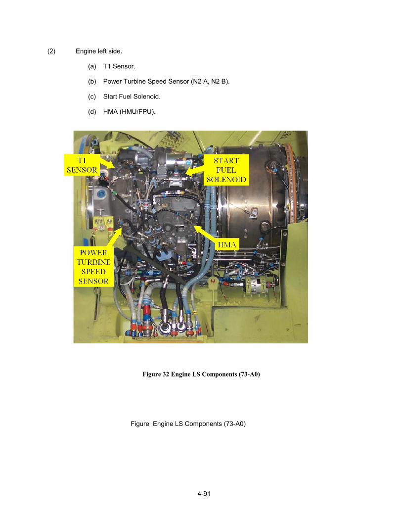
4-91
(2) Engine left side. (a) T1 Sensor. (b) Power Turbine Speed Sensor (N2 A, N2 B). (c) Start Fuel Solenoid. (d) HMA (HMU/FPU).
Figure 32 Engine LS Components (73-A0)
Figure Engine LS Components (73-A0)

4-92
c. System interfaces (1) The engine mounted Hydro-Mechanical Assembly (HMA) interacts with the airframe mounted Digital Electronic Control Unit (DECU). The DECU receives signals from airframe and engine, controls engine operation, and provides engine system failure indications. d. General operation. (1) The HMA (Hydro-Mechanical Unit (HMU)/Fuel Pump Unit (FPU) mounted on the accessory gearbox, is divan by the gas produced section of the engine though shafting. The FPU is a high-pressure pump assembly providing high-pressure fuel for engine consumption and system operation. The HMA is the controlling part of the assembly providing an all-electronic engine fuel metering system in the primary mode and a hydraulically operated fuel metering system in the reversionary mode. The reversionary system serves as the back-up fuel metering system. While not as operationally fast as the primary system it is still more reliable than the previously installed hydro-mechanical fuel control. Under normal operation the reversionary system shadows the operation of the primary system. As a shadow system it is completely independent of the primary system using unique system in-puts and controlling the operation of the engine without aid of the primary engine control system. An independent engine overspeed protection system protects against engine overspeed in both channels of operation.

4-93
Figure 33 FADEC Functional Diagram (73-A0)
e. Purpose (1) The HMA is comprised of the Hydromechanical Metering Unit (HMU) and the Fuel Pump Unit (FPU). The FPU increases fuel pressure. Providing fuel pressure for engine operation and the operation of components with-in the HMU. The HMU Controls fuel pressure/flow for engine operation. f. Location (1) Mounted on the engine accessory gearbox in the same location as the hydro-mechanical fuel control.

4-94
g. Description/Features (1) Weight 31.6 lbs. (14.4 kg) (2) Gear Pump Rating 8100 PPH/700 PSI 100 N1 speed (3) Boost Stage - Pressure regulated jet pump (770 to 9260 PPH) (4) Metering Valve - Flat plate orifice, wiper controlled. (5) Primary Control - Stepper motor, direct drive to valve wiper. (6) Reversionary Control - Stepper motor, control through Wf/P3 servomechanism, and P3 servomechanism, via the mechanical multiplier. (7) Bleed Band Control. (a) Primary Control. Electronic (solenoid controlled valve). (b) Reversionary Control. Hydromechanical (hydromechanical speed sensor). (8) Speed Sensing (a) Primary Control. Magnetic sensor, Alternator winding. (b) Reversionary Control. Alternator Winding, hydromechanical speed sensor for bleed band control

4-95
Figure 34 HMU View 1 (73-A0)
h. External connections to the HMA include: (1) Three Electrical Connectors: (a) Alternator connector - at the HMU alternator, supplies electrical power to the primary channel and gas producer N1 B speed signal. (b) Main HMU connector - primary mode control functions and gas producer N1 A speed signal. (c) Reversionary stepper motor connector - reversionary mode control functions. (2) Three Pneumatic Ports: (a) Compressor Discharge Pressure (CDP) (P3) sensing. (P3 servomechanism and DECU). (b) Modulated air pressure control port (bleed band control).

4-96
(c) Ambient relief port (bleed band control). (3) Three Fuel Connections: (a) Fuel inlet. (b) Fuel Out Metered. (c) Fuel Out Start. (4) Seal Drains: (a) HMA input shaft. N (b) HMA cavities. WARNING: Liquid fuel present at the seal drain could indicate fuel leaking into the HMU dry cavities in which are housed the HMU electronic components or the HMA mounting flange. The seal drains connect to the engine drain system.
Figure 35 HMU View 1 (73-A0)

4-97
Figure 36 HMU (73-A0) i. Description/Features HMA OPERATION
(1) PRIMARY MODE
(a) Fuel Pump. (b) Metering Valve. (c) Pressurizing and Shutoff Valve. (d) Primary Stepper Motor. (e) Solenoid Valve (Bleed Band Operation). (f) Pri/Rev Change-Over Solenoid. (2) REVERSIONARY MODE (a) Fuel Pump. (b) Metering Valve. (c) Pressurizing and Shutoff Valve. (d) Reversionary Stepper Motor.

4-98
(e) Wf/P3 Servo. (f) Mechanical Multiplier. (f) P3 Servo.
(g) Hydraulic Speed sensor (Bleed Band Operation).
Figure 37 FADEC Functional Block Diagram (73-A0)
j. Fuel pump unit (FPU) (1) Purpose: Receive fuel from the low-pressure components of the engine fuel system. Provide fuel under high pressure for engine operation and provide fuel under pressure to be used as the hydraulic medium for the operation and cooling of the components with-in the HMU.

4-99
(2) Location: Mounted to the engine accessory gearbox. (3) Operation: The FPU jet induced gear pump delivers pressurized fuel to the HMU flat plate-metering valve. Fuel flow and pressure are determined by pump speed. The action of the FPU is the same for either the primary or reversionary mode of operation. The FPU driven gear is powered by a splined input shaft, and meshes with a pump driven gear. The gear pump is a positive displacement; pressure loaded pump capable of delivering a maximum flow of 26 GPM @ 4200 RPM. A jet pump utilizes bypassed fuel from the HMU metering head regulator to increase the gear pump inlet pressure. A pressure regulator built into the jet pump controls the jet pump output pressure by varying the nozzle area of the jet. The metering head regulator in the HMU maintains a constant pressure differential across the metering valve so that fuel flow to the engine will vary in proportion to the metering valve position. Fuel flow in excess of the engine requirement is bypassed back to the FPU to be utilized by the jet pump. A high-pressure relief valve is adjusted to limit the gear pump discharge pressure to 750 PSI. The 24-mesh screen, filters HMU bypassed fuel prior to the jet pump. Should the screen become clogged it will bypass flow 15 PSID. An output shaft between the gear pump and the HMU provides drive power to the HMU internal components.

4-100
k. Hydromechanical Metering Unit (HMU) internal components. HMU Schematic See Appendix A (1) Purpose: Govern fuel flow for engine operation. (2) Location: Component of the HMA, mounted on the Fuel Pump Unit (FPU). (3) Operation. The following components function in the same manner in both the primary and reversionary modes. (4) Metering valve. (a) Meters fuel flow based on the position of a spring-loaded wiper, which rotates over an orifice in the flat metering by the primary stepper motor, which is controlled by commands from the DECU. In the reversionary mode, the wiper is controlled mechanically by linkage, with inputs from the Wf/P3 servomechanism and P3 servomechanism (transducer). The fuel type is not a factor in the operation of the metering valve. (5) Metering head regulator. (a) Regulates fuel pressure to the metering valve and bypasses excess pump discharge flow back to the fuel pump inlet. Ports all metering valve inlet pressure back to the fuel pump inlet with the ECL in the STOP position. (6) Pressurizing and shutoff. (a) Provides the means for maintaining sufficient backpressure for the pump at all fuel flow schedules, and provides a positive fuel shutoff when the ECL is placed in the STOP position. (7) Windmill bypass valve. (a) A cam operated valve, operated by the reversionary stepper motor. The valve when activated relieves the control pressure of the metering head regulator causing the fuel pressure to drop at the metering valve, in-turn decreasing metering valve downstream pressure at the pressurizing and shutoff valve. With the pressurizing and shutoff valve closed the fuel flow to the engine fuel nozzles is shutoff. (8) Magnetic speed sensor: The magnetic speed sensor provides the main speed signal to the DECU primary channel (N1 A).

4-101
(9) Alternator: Serves as a power supply to the DECU primary channel. Provides sufficient electrical power above 49% N1 speed (low idle is 50%) to operate the DECU/HMU primary control system. A dedicated winding in the alternator provides the DECU with a redundant speed signal (N1 B). The following components function in the primary mode of operation only. (10) Primary stepper motor: Rotates the main metering valve shaft, positioning the metering valve wiper over the metering valve orifice. Full travel of the metering valve wiper is approximately 55 degrees. The stepper motor is capable of 500 steps/second. Full travel of the metering valve wiper takes approximately one second. (11) Metering valve feedback: The metering valve shaft through a mechanical linkage directly drives the primary feedback potentiometer. Provides the DECU with metering valve position, creating a closed loop system. (12) Bleed solenoid valve: The bleed solenoid valve is controlled by the DECU preventing engine surge. In the primary mode the position of the bleed band is either full open or fully closed (No modulation). De-energizing the bleed solenoid will open the bleed band, with the solenoid energized the engine bleed band will be closed. (13) Primary/reversionary change over solenoid valve: In the primary mode, the solenoid is energized, disabling the reversionary WF/P3 servomechanism. With a hard fault in the DECU primary channel, or if the reversionary mode is selected by the pilot, the solenoid is de-energized and the reversionary mode is enabled. Fuel pressure is ported to the Wf/P3 servo and to the hydromechanical speed sensor for reversionary mode operation. (14) Reversionary stepper motor ( primary mode): The reversionary stepper motor shadows the operation of the primary stepper motor, positioning the Wf/P3 servo contour valve in response to commands from the reversionary channel of the DECU. Positions a cam activating the windmill bypass valve, which will cause the fuel pressure to be removed from the metering head regulator, metering valve, and pressurizing and shutoff valve, effecting engine shutdown.

4-102
The following components function only in the reversionary mode. (15) Reversionary stepper motor: The reversionary stepper motor provides a means for positioning the Wf/P3 servo contour valve in response to commands from the reversionary channel of the DECU. Positions a cam activating the windmill bypass valve, which will cause the fuel pressure to be removed from the metering head regulator, metering valve, and pressurizing and shutoff valve, effecting engine shutdown. (16) Power lever angle (PLA) feedback potentiometer: The reversionary stepper motor shaft directly drives the PLA feedback potentiometer. Provides the DECU reversionary channel with the reversionary stepper motor position. Reversionary Wf/P3 Servomechanism positions the metering valve wiper through the mechanical multiplier linkage, controlling engine fuel flow in the reversionary mode. P3 Servomechanism (transducer) in conjunction with the reversionary Wf/P3 servomechanism, Controls fuel flow by providing an input to the mechanical multiplier linkage proportional to P3. (17) Hydromechanical speed sensor: The hydromechanical speed sensor controls the operation of the piston operated bleed valve, controlling the engine bleed band in the reversionary mode. (18) Piston operated bleed valve: Changes in this pressure will operate the bleed band actuator, providing engine surge protection. (19) Mechanical multiplier: Position the metering valve wiper over the metering valve discharge orifice, metering fuel flow in the reversionary mode. The mechanically linkage in positioned based on inputs from the Wf/P3 servomechanism and P3 servomechanism (transducer).

4-103
V POWER LEVER ANGLE MECHANISM DIAGRAM .

4-104
DECU a. Purpose (1) The EMC-32T Digital Electronic Control Unit (DECU) is a dual channel digital controller with independent primary and reversionary channels providing control of the fuel used for engine operation. A stand-alone analog overspeed limiting circuit provide electronic protection against engine overspeed. b. Location (1) Two DECU’s are mounted inside the aircraft cabin at STA 400. c. Description/Features (1) The following major components make up the DECU housing, board assemblies, pressure transducers, connectors and flexible circuits. d. DECU specification (1) Weight 3.4 lbs. (6.1 kg). (2) Dimensions 13.8 in long, 8.7 in wide, 4.21 in height. (3) Installation Mounted to the airframe with visco elastic isolators. (4) Construction: Cast aluminum housing, protecting the internal operation from, Electromagnetic Interference (EMI). Radio Frequency Interference (RFI). Electromagnetic Pulse (EMP). Environmentally protected. Multi-layer printed circuit (PC) boards internally connected by multi-layer flexible circuits. (5) Operating environment Minus 54º C. to 85º C. Sea level to 25000 ft. (6) Reliability 10, 000 Hrs. Mean Time Between Failure (MTBF). e. DECU housing (1) The DECUs internal electronic components are protected from EMI, RFI, and EMP; lightning, water and contaminants with sealed and shielded aluminum housing. O-rings and gaskets prevent external contaminants from entering the DECU. Each printed circuit (PC) board assembly is coated to keep contaminants away from the conductive surfaces. All components within the DECU are ruggedly mounted to withstand vibration and shock. The DECU contains a separate EMI/RFI compartment that contains the RFI board, preventing internal EMI and high-energy (lightning strike) transients from reaching the internal DECU control circuitry. This configuration also prevents DECU generated EMI from exiting the DECU.

4-105
Figure 38 DECU (73-A0)
f DECU board assemblies. Multi-layer printed circuit (PC) boards preserve the noise-free electrical integrity and ensure good thermal performance. (1) The four PC boards: (a) Computer. (b) Analog. (c) Power Supply. V (d) RFI. (2) Are thick multi-layer assemblies, conformally coated and closely bolted, reducing the effects of vibration. Board functions are arranged to maximize the modularity of the internal assemblies. Computer Board-contains all the circuitry for the processing components of the primary and reversionary channels. Analog Board-provides the circuitry for converting signals from the external transducers to a digital format suitable for input to the primary and reversionary channels and the analog overspeed circuitry. Power Supply Board-provides the circuitry to power the primary and reversionary channels and engine and airframe interface components. RFI Board- contains the filtering devices to reduce the amplitude of the external noise as it enters the DECU, as well as the noise generated internally by the DECU.

4-106
Figure 39 DECU (73-A0) g. DECU flexible printed circuits. (1) Internal connections between the DECU external connectors and the RFI board and between the RFI filters and the remaining boards are achieved with flexible printed circuits. These are lighter, more reliable, and allow for faster DECU assembly as compared to conventional point to point wiring. h. DECU power supplies. (1) The digital electronic control unit contains separate digital processors for the primary and reversionary channels plus isolated interface circuitry, allowing independent operation of each channel. Each channel is powered by dual independent power sources. The HMU 30 Vdc alternator powers the primary channel with the engine running (N1> 49%) or by the aircraft 28 volt No. 1 (2) ESSENTIAL; DC BUS. The primary power supply selects the higher of the two voltages: (2) Aircraft DC electrical system 28 volts dc (No. 1 (2) ESSENTIAL DC BUS). 2. HMU alternator output voltage (30 volts ac) rectified to (28 volts dc).

4-107
(3) The reversionary channel receives 28-volt electrical power from contact A1 of the essential bus relay or 24 volts from pin 4 of the external power reset switch. Diodes protect the system from an electrical reverse flow. (4) The control panel back-up (B/U) power switch will only remove power from the Primary channel. To remove power from the Reversionary channel the battery must be disconnected or the REV CONT circuit breaker must be open. (5) The FADEC system is capable of starting both engines in the primary or reversionary mode.
(6) Electrical connections to the DECU are made via two 61-pin connectors. (PL1 and PL3), A third 13 pin connector (PL2) is used for connecting an FADEC Diagnostic Computer.

4-108
(7) DECU pressure transducers : Two temperature compensated 0 to 20 psi pressure transducers, (P1) Atmospheric pressure and (P3) Compressor Discharge Pressure (CDP) are mounted in the DECU housing. O-rings provide sealing for the fittings that protrude through individual holes in the DECU cover assembly. The P1 transducer senses atmospheric pressure that will vary with altitude. The transducer fitting is covered with a vented cap. The P3 transducer is connected with flexible pneumatic line to the engine P3 CDP tap via the HMU. CDP is utilized by the DECU for sensing engine stall or surge conditions.

4-109
P3 CONDENSATION DRAIN Drains the P3 system of accumulated moisture. A glass vile with a spring loaded check valve will provide visual indication of the accumulated moisture.
WARNING/CAUTION Do not depress the check vale while the engine is operating, this will cause the DECU to lose its P3 reference pressure. Do not use the lower flats of the vile to remove or install the vile/check valve assembly, always use the upper flats.
Figure 40 FADEC P3 Drain Check Valve
Figure 41 FADEC Power Supply System (73-A0)

4-110
j. ELECTRICAL HARNESSES B (1) Description/Features: Design Philosophy - The FADEC electrical harnesses were designed to allow replacement of the same pin twice without degrading the performance of the harness assembly. The outer protective harness covering is convoluted tubing constructed with Fluorinated Ethylene Propylene (FEP) inner and outer jackets. Sandwiched between the jackets are two layers of nickel-coated copper braid. Harnesses are sealed environmentally. All fittings, transitions, coupling nuts and tubes are nickel-plated aluminum. Ferrules are corrosion resistant steel. All harness connector ends are color coded by harness function and identified with a connector P-number. Color band and number identification: (2) PRIMARY HARNESS - YELLOW BAND.
Figure 42 Primary Harness (73-A0)

4-111
(3) REVERSIONARY HARNESS - BLUE BAND.
Figure Reversionary Harness (73-A0)

4-112
(4) Accessory harness: GREEN BAND Engine signals (N1, Oil Low, Oil Temp, Oil Pressure. (5) The identification band is clearly visible on main trunk of harnesses and lists the P/N, S/N Rev letter, and vendor identification. k. Measured gas temperature (MGT) harness. (1) Purpose: The Measured Gas Temperature (MGT) harness provides Power Turbine Inlet Temperature (PTIT) signals directly to the DECU. PTIT is provides to the cockpit indicator form the DECU. (2) Location: The thermocouples are located in the engine turbine section. (3) Description/Features: The engine temperature measuring components consist of five dual element (total of ten elements) temperature probes, each of the dual element assemblies is connected externally to bus bars located on the engine fire shield. The probes protrude into the gas flow at the power turbine inlet (T 4.5) between the No. 2 and No. 3 turbines. The probes react to variations in turbine inlet temperature by varying an output voltage proportional to the temperature of the gas flow. The MGT portion of the harness is not repairable.
Figure PTIT Harness (73-A0)

4-113
l. Thrust control position transducer . (1) Purpose: In primary mode provides the FADEC system (DECU) with signals related to the travel and rate of thrust lever movement. In reversionary only the amount of thrust lever movement is provided for FADEC operation. (2) Location: In the flight control closet, attached to the components of the thrust artificial feel system. (3) Description/Features: The thrust control position transducer replaces the dual element resistor (drop eliminator), and is installed in the same location. When the thrust lever is moved, the transducer varies a voltage signal to the DECUs relative to the distance and rate the lever is moved. (a) In primary mode, (load anticipation) the DECU uses this signal to determine the distance and rate the thrust lever is being moved and thereby anticipates a required rate of acceleration/deceleration to precisely maintain the N2 speed. In the reversionary mode (load scheduling) the distance the thrust lever is moved provides a signal to adjust the DECU N2 governor. (b) In the reversionary mode, the pilot uses the DEC/INC switches for load matching and fine tuning the governed N2 speed. NOTE: Sometimes referred to as: Thrust Position Sensor Collective Pitch (C/P) Sensor Rotor Thrust Lever (RTL) Sensor Linear Variable Displacement Transformer (LVDT).
Figure Thrust Position Sensor (73-A0)

4-114
m. T1 Temperature sensor. (1) Purpose: Provides ambient air temperature for FADEC operation. (2) Location: Attached to the engine air inlet housing at the 10 o’clock position, the probe protrudes into the inlet air stream. (3) Description/Features: The T1 temperature sensing system consists of a variable resistance temperature sensor that detects the engine air inlet temperature (ambient), providing the DECU with a signal proportional to the temperature of the engine inlet air. The temperature signal is processed and utilized within the DECU.
Figure 714A T1 Sensor (72-A0

4-115
n. Power turbine magnetic speed sensor. (1) Purpose: Provides the FADEC system with redundant electronic signals related to the speed of the engine power turbine system. (2) Location: Mounted on the engine left side on the accessory gearbox. (3) Description/Features: A magnetic sensor consists of a cylindrical permanent magnet and a wire -wrapped soft iron core. A ferrous metal interrupter (cylinder with symmetrically raised segments around it’s circumference), driven by the gearing of the accessory gearbox the cylinder rotates in close proximity to the end of the sensors at a speed relative to the power turbine system. (a) The magnetic lines of flux generated by the magnet are low while a raised segment of the interrupter is positioned away from the end of the magnetic sensor. When a raised ent of the interrupter is passed across the end of the magnetic sensor the lines of magnetic flux are strengthened and drawn inward. (b) The magnetic flux lines passing across the wire coil will induce a voltage proportional to the rate of change of the lines of flux. The speed signal transmitted to the DECU is proportional to the speed at which the raised segments of the interrupter pass across the end of the magnetic sensor. The function of the magnetic sensor is the same for all engine speed sensors (i.e. engine gas producer speed and dual pick-up power turbine speed sensors. NOTE: The N1 B speed signal is a function of the HMU-driven alternator windings. The N1 speed signal generated by the magnetic sensor mounted on the rear of the engine driven oil pump is for the cockpit N1 speed indication and not utilized by the FADEC system.

4-116
Figure Power Turbine Speed Sensor (73-A0)

4-117
o. Start fuel solenoid valve. (1) Purpose: Provide fuel to the two engine start fuel injectors for engine starting. (2) Location: The start fuel solenoid is mounted on the left side of the engine just below the main fuel filter assembly. (3) Description/Features: It consists of a solenoid, spring loaded valve, and 100-mesh filter. The DECU electrically activates the solenoid. With the valve energized to the open position, start fuel flows from the HMA fuel pump, through an external fuel line to the two start nozzles located on the combustor assembly.
Figure Start Fuel Solenoid Valve (73-A0)

4-118

4-119
P. Overspeed solenoid valve. (1) Purpose: Provides power turbine overspeed protection. (2) Location: The overspeed solenoid valve is mounted on the right side of the engine, between the oil cooler and the dual chip detector. (3) Description/Features: The valve consists of an electrically controlled valve, spring-loaded to the full open position. The solenoid is controlled by the DECU. If a power turbine overspeed is detected an electrical signal is sent to the overspeed solenoid, activating the valve and reducing engine fuel flow. (a) Fuel flow can be reduced to the level of flow required to maintain the engine at idle RPM. The solenoid remains activated until the overspeed condition no longer exists, and will reactivate should a power turbine overspeed reoccur. (b) The valve will open as the power turbine section of the engine slows below the overspeed trip point and close as the power turbine section increases speed above the trip point.
Figure Overspeed Solenoid Valve (FADEC) (73-A0)

4-120
Figure Overspeed Solenoid Valve (FADEC) (73-A0)

4-121
q. FADEC control panel. (1) Purpose - Make FADEC system control selections. (2) Location - On the overhead switch panel. (3) Description/Features (a) NR SELECTOR - (N2SET) A rotary switch which provides variable rotor rpm control, when operating in the primary mode. The labeled positions are 97, 100, and 103. With the engine condition levers (ECLs) in the FLT position, NR will be maintained at the selected speed. The selector is detented at the 100 position only. Rotor speed selections can be set from 97 to 103. (b) 1 AND 2 PRI/REV SELECT SWITCHES - Two switches, labeled PRI, and REV, provide control of the primary and reversionary modes of operation. In the REV position, electrical power is removed from the primary channel. (c) ENG START SWITCH - A three-position switch, spring-loaded to the center position. Labeled 1 and 2 used to initiate the start sequence of the selected engine. (d) LOAD SHARE SWITCH - A two-position switch used to select either PTIT or TORQUE as the parameter to be used by the FADEC system as the basis for engine load matching. (e) B/U PWR SWITCH -- Controls the airframe power (Essential DC bus 1 or 2) to the FADEC system primary channel. (f) OSPD 1 or 2 the switch is used to perform the N2 overspeed system test. Does not operate above 81.3% N2.
Figure FADEC Control Panel (RAF & ECP D 218) (73-0)
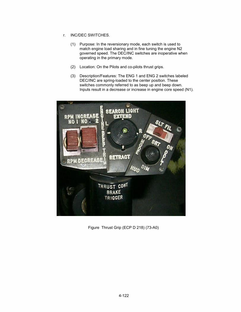
4-122
r. INC/DEC SWITCHES. (1) Purpose: In the reversionary mode, each switch is used to match engine load sharing and in fine tuning the engine N2 governed speed. The DEC/INC switches are inoperative when operating in the primary mode. (2) Location: On the Pilots and co-pilots thrust grips. (3) Description/Features: The ENG 1 and ENG 2 switches labeled DEC/INC are spring-loaded to the center position. These switches commonly referred to as beep up and beep down. Inputs result in a decrease or increase in engine core speed (N1).
Figure Thrust Grip (ECP D 218) (73-A0)

4-123
s. Engine condition levers (ECL). (1) Purpose: Control the engine operation during STOP (shutdown), GND (ground operation), and FLT (flight operations). (2) Location: On the cockpit Overhead Switch Panel. (3) Description/Features: The ECLs labeled ENG 1 and ENG 2 are three position levers, labeled STOP, GND, and FLT. Each lever independently controls the start, operating speed, and shutdown of the respective engine. STOP - 0 degrees, GND - 30 degrees, FLT - 60 degrees. NOTE: Movement of the ECL between the GND and FLT positions will effect the ECL position input to the DECU in both the primary and reversionary modes, adjusting the metering valve position based on ECL position. An intermediate position between GND and FLT can be selected and will effect FADEC system operations.
Figure ECL (73-A0)

4-124
Figure ECL FADEC System (ECP D218) (73-A0

4-125
PRIMARY SYSTEM INTERFACE Controls for primary channel engine operation include: (1) Engine Start Switch (11) Control Engine Start and Ignition Relays
(2) Engine Condition Lever (ECL) (12) Schedules Core engine Speed (N1) and
Controls Fuel Shutoff
(3) NR Selector (N2SET) (13) Sets Power Turbine Speed (N2)
(4) Thrust Control Position Transducer (14) Load Anticipation
(5) PRI/REV Switch (15) Selects Operation of the PRI or REV Mode
(6) B/U Power Switch (16) Removes Electrical Power from the Primary Channel
(7) Load Share Switch (17) Selects PTIT or Torque for engine load sharing
(8) Engine Overspeed Test Switch (18) Activates Overspeed Test Function N2 < 81.3%)
(9) Engine Power Assurance Test Switch (19) Perform Tmargin test.
(10) Hexadecimal Display (20) ENG TEMP margin

4-126

4-127
FADEC Block Diagram (73-A0)

4-128
a. HMU OPERATION (OVERVIEW). (1) FUEL PUMP. (a) PRIMARY MODE OVERVIEW. 1. METERING VALVE. 2. PRIMARY and REVERSIONARY STEPPER MOTORS. 3. PRESSURIZING AND SHUTOFF VALVE. 4. OVERSPEED SOLENOID VALVE. 5. SOLENOID VALVE CONTROL OF THE BLEED BAND ACTUATOR. (b) REVERSIONARY MODE OVERVIEW. 1. PRI/REV CHANCE-OVER SOLENOID. 2. MECHANICAL MULTIPLIER. 3. Wf/P3 SERVOMECHANISM. 4. P3 SERVOMECHANISM. 5. REVERSIONARY STEPPER MOTOR. 6. HYDRAULIC SPEED SENSOR CONTROL OF THE BLEED BAND ACTUATOR.
b. PRIMARY CHANNEL FUNCTIONS. (1) In the primary control mode, the system performs a number of functions related to controlling the engine during the start and operational phases. The primary channel control function cycle rate is 24 ms (41.6 cycles/sec). The Engine history-recording rate is 192 ms (5 cycles/sec). (a) Functions. 1. Engine starting. 2. Engine shutdown. 3. Power available. 4. Acceleration and deceleration. 5. Surge recovery.

4-129
6. Steady state flight conditions. 7. Transient flight conditions. 8. Temperature limiting. 9. Power turbine overspeed limiting. 10. Power assurance test. 11. Fault code recording. 12. Engine history recording. (2) The control scheme is based on the computation of a parameter referred to as NDOT (*). (NDOT is directly proportional to the demanded engine fuel flow). Different values of NDOT are computed by each of the following control functions: (a) Acceleration. (b) Temperature Limiter. (c) Power available. (d) Power turbine governor, (NDOT modified by the selected (PTIT or TORQUE) for load sharing). (e) Deceleration. (3) These values of NDOT are passed to the NDOT select logic. This selected value NDOT is checked against surge detection and recovery logic and input to the NDOT governor. (4) The governor produces a fuel flow demand that after, being checked against fuel flow limitations, is input to the primary stepper motor control logic, after being adjusted by the fuel flow feedback signal from the primary potentiometer. The resulting fuel flow error generates a sequence of phase patterns (steps) that will be output to the primary stepper motor in order to ncrease or decrease fuel flow. NOTE: (*) DOT - is defined as a derivative (change) over time and can be applied to a variety of parameters, speed (NDOT), temperature (TDOT), or pressure (PDOT).

4-130
c. LOAD SHARING.
(1) In non FADEC controlled aircraft the pilots monitor the load share requirements and adjust the engines through a process called beeping, where the engine outputs (torque, PTIT, or N1) are matched the equalize the engine workloads. With the FADEC system Torque, PTIT can be selected to automatically control the engine load sharing requirements. If the selected system fails the system is designed to default to N1 load sharing. If the selected load share signal is loss between the DECU’s or one of the two FADEC systems is in the reversionary mode load sharing is disabled. Load sharing is accomplished by bringing up the low performing engine, by adjusting the demanded power turbine speed than reducing the output of both engines simultaneously until the desired power output is shared by both engines. The load sharing circuits are by design slow acting so as not to create an unstable engine condition.
d. HMU PRIMARY OPERATING MODE .
(1) The HMU components used in the primary control mode are the metering valve, metering head regulator, pressurizing and shutoff valve, windmill bypass valve, primary control stepper motor, primary feedback potentiometer, bleed valve solenoid, primary/reversionary change-over solenoid valve, alternator, and N1 speed sensor. (2) The primary/reversionary changeover solenoid valve is energized by the DECU overriding the WF/P3 servomechanism, and hydromechanical speed sensor. This allows the fuel-metering valve to be directly positioned by the primary stepper motor and gearhead assembly. The four phase primary control stepper motor positions the metering valve in response to signals from \ the DECU increasing or decreasing engine fuel flow, the feedback potentiometer signals the DECU with the corrected position of the metering valve which cancels the signal to the stepper motor (closed-loop operation).
e. PRIMARY MODE ENGINE STARTING.
(1) The method of control during engine starting consists of ramping fuel flow from a lightoff fuel flow level to a ground idle fuel flow. Temperature rate limiting is provided in the start logic. The net ramp rate is biased by altitude compensation. This fuel flow is then compared with a temperature limit.

4-131
(2) GROUND STARTING, PRIMARY MODE (NORMAL OPERATION, NO FAULTS). (a) Set the ECL to GND. (b) Hold start switch until N1 > 10%. (c) Primary channel will automatically control the start
sequencing.
1. Starter. 2. Fuel flow to start fuel nozzles. 3. Ignition. 4. Fuel flow to main fuel nozzles . (d) Temperature limiting (after lightoff PTIT > 760º c) Reduces fuel flow to 100 PPH minimum. (e) Overtemperature during start (abort). 1. Fuel shutoff if PTIT > 815.5ºC 2. ENG 1 (2) FAIL indication. 3. ECL TO STOP resetting the start mode . (f) AIR STARTS. 1. Procedures are the same as for a ground start
f. PRIMARY MODE ENGINE SHUTDOWN . (1) When the ECL is moved to the STOP position, the primary system drives the metering valve stepper motor to its fuel shutoff position (40 PPH). This will normally cause a combustor blowout, in which case the engine will spool down and the fuel pressure will drop below the HMU pressurizing and shutoff valve setting, causing the valve to close and shutoff fuel to the engine. To ensure proper fuel shutoff the reversionary control will drive the reversionary stepper motor to the shutoff position positioning the windmill bypass shutoff valve and causing the metering head regulator to bypass total pump output. This drops fuel pressure below the pressurizing and shutoff valve setting, completely shutting off fuel flow to the engine. The primary stepper motor maintains the metering valve at the 40 PPH fuel flow position; ensuring sufficient fuel flow pressure will be available for a subsequent engine start.

4-132
(2) PRIMARY MODE ENGINE SHUTDOWN. (a) ECL moved to GND to allow normal engine cool down . (b) ECL to STOP. 1. Primary system closes the metering valve to the
2. Reversionary mode will effect complete shutoff of fuel when ECL is moved to STOP . 3. The shutoff feature is the only function of the reversionary mode that impacts the primary mode.
g. PRIMARY MODE POWER AVAILABLE .
(1) The ECL sets the reference speed of the N1 governor. With the ECL in the GND position, the control will maintain corrected engine idle speed. With ECL in the FLT position, the N1 governor sets the maximum allowable core engine speed (N1) to the emergency power limit. When ECL is advanced from GND to FLT, FADEC will accelerate the engine to obtain the governor power turbine set speed (N2).
(2) POWER AVAILABLE. (a) Ground Idle . (b) ECL to GND . (c) Idle speed adjusted for engine inlet temperature. 1. N1 = 50% Cold Day (-65ºF). 2. 55% STD Day (59ºF). 3. 59%Hot Day (135ºF). (3) GROUND TO FLIGHT TRANSITION. (a) ECL moved to FLT position. NOTE: (No special rate limitations required with FADEC).
(b) FADEC will accelerate engine to n2 governor set speed (rotor rpm selected by the NR switch on the FADEC control panel). (c) ECL FLT position sets N1 governor to emergency power speed limit.

4-133
h. PRIMARY MODE TRANSIENT ENGINE CONTROL. (1) NDOT Acceleration and Deceleration: Engine acceleration is scheduled as a function of core engine speed (N1). When the acceleration is the lowest value being demanded by the four control loops, the NDOT governor will control engine fuel flow to attain the demanded acceleration schedule from idle to maximum power. When the deceleration schedule is higher than the selected low of the four control loops the NDOT governor will control engine fuel flow to attain the demanded NDOT deceleration schedule. In normal flight operation, the DECU is working to hold N2 constant. Large changes in rotor thrust via the thrust lever (RTL) will cause the DECU to transfer to the acceleration or deceleration schedules. (2) Compressor Bleed Actuator Control the FADEC system interfaces with the engine bleed band actuator, opening the bleed band during engine acceleration or deceleration or when an engine surge is detected. A bleed valve solenoid valve within the HMU controls the bleed actuator. (3) Surge Recovery the compressor discharge pressure (P3) is used to detect an engine surge that is determined by P3DOT. If a surge condition occurs, the bleed valve is opened and the acceleration and deceleration schedules are reduced by 25%. When the engine recovers to a steady state condition the surge flag is disabled.
FADEC Functional Block Diagram (73-A0)

4-134
i. PRIMARY MODE STEADY STATE FLIGHT CONDITIONS .
(1) Pilot procedures are the same as with the previous engine fuel control system except that INC/DEC (beep) trim is not required to hold set speed or match engine torque After the engine is brought on line, the proportional/integral governor maintains the set speed constant. The load sharing system operates to match the selected load share (PTIT or TORQUE) signals by slowly increasing the power of the low load engine. After the engine outputs are synchronized the PTIT or Torque (whichever is selected) output of both engines are simultaneously reduced to the required level. Rotor speed is selected via the cockpit NR selector (FADEC control panel). The selection sets the power turbine output proportional to the selected rotor speed.
j. PRIMARY MODE TRANSIENT FLIGHT CONDITIONS.
(1) Anticipation: When repositioning the thrust lever at a rate of > 5%/sec, the output of the power turbine governor is reset to cause the engine to accelerate or decelerate to meet the impending change in power requirement. This function helps to minimize rotor droop or overspeed during a power transient. (2) Torque Smoothing: Minimizes speed and torque oscillation enhancing flight stability. (3) Recovery from Autorotation: When the rotor is decoupled, the control senses rotor speed decay and automatically accelerates the engine to increase power turbine speed to recouple before an underspeed occurs. (4) Primary Mode Temperature Limiter: Temperature limiting is scheduled as a function of core engine speed. When the temperature limiter is calling for the lowest NDOT setting, the control through the operation of the proportional/integral governor will provide a constant engine temperature limit.

4-135
a. TRANSFER TO REVERSIONARY.
(1) The reversionary channel serves as a backup to the primary mode and is a full authority digital electronic engine controller. Providing all essential engine and rotor speed control functions. Although the reversionary mode is much simpler design with some of the enhancing features of the primary mode eliminated. The reversionary mode will still provide the engine control necessary for mission completion at the expense of a higher cockpit workload. (2) The reversionary channel electronics have been shadowing the primary channel. The reversionary channel in relationship to the current demanded engine fuel flow is always positioning the reversionary stepper motor (disengaged in the primary mode). Switchover to the reversionary mode is automatic should a hard fault occur in the primary mode. The reversionary mode can also be selected through the use of a pilot activated switch on the FADEC control panel.
b. REVERSIONARY CONTROL (Transfer to Reversionary).
(1) Reversionary Channel (REV 1 (2) OFF). (2) When in primary, the reversionary control tracks N1. (3) Pilot selects reversionary or primary channel failure . (a) Cockpit Display - FADEC 1 (2) ON. (b) Normal transition to reversionary will be smooth, normally not requiring pilot action. (4) If the reversionary channel is hard faulted (REV 1 (2) ON). (a) Primary system fails to fixed fuel flow (failed fixed). (b) If pilot selects reversionary, control fails fixed to reversionary setting.. (5) Cockpit display ENG 1 (2) FAIL & FADEC 1 (2) Indication ON. (6) Cockpit Controls Indications. (a) Cockpit Display FADEC 1 (2) ON. (b) The effected engine does not respond to control changes. (c) Indicated torque splits .

4-136
FADEC Functional Block Diagram (73-A0)

4-137
c. REVERSIONARY SYSTEM INTERFACE.
Controls for reversionary channel engine operations include: (1) Engine Start Switch
Control Engine Start and Ignition Relays
(2) Engine Condition Lever (ECL) Schedules Core engine Speed (N1) and Controls Fuel Shutoff
(3) Thrust Control Position Transducer
Load Scheduling
(4) PRI/REV Switch
Selects The REV Mode
(5) Engine Overspeed Test Switch Activates Overspeed Test Function N2 < 81.3)
(6) Power Assurance Test Switch Hexadecimal Display ENG TEMP margin
(7) INC/DEC Switch (beep) Trims Core Engine Speed (N1)
FADEC Block Diagram (73-A0)

4-138
d. REVERSIONARY CHANNEL FUNCTIONS.
NOTE: In the reversionary control mode, the system performs a number of functions related to controlling the engine during the start and operational phases. (1) The reversionary channels control function cycle rate is also 24 ms (41.6 cycles/sec). (2) FADEC OPERATIONS. (a) Engine Starting. (b) Engine Shutdown. (c) Core Engine Speed Governor . (d) Proportional Power Turbine Governor . (e) Wf/P3dot Acceleration and Deceleration. (f) Temperature Rate of Change Limiting. (g) Temperature Limiting. (h) Hydromechanical Bleed Band Control. (i) Inc/Dec Trim Function. (j) Fault Code Reporting. (3) The reversionary channel utilizes the position of the engine condition lever (ECL), power turbine inlet temperature, core engine speed, and thrust lever position to establish the required fuel flow for engine operation. (a) Additional inputs are from the INC/DEC switch on the thrust grip. (4) The reversionary stepper motor control logic, after being adjusted by the fuel flow feedback signal from the reversionary potentiometer, results in a fuel flow error Signal. This generates a sequence of phase patterns (steps) that will be output to the reversionary stepper motor in order to increase or decrease fuel flow.

4-139
FADEC Functional Block Diagram (73-A0)
(5) The reversionary control scheme is based on the computation of a parameter referred to as N1SET (demanded engine core speed). (6) Different values of core engine speed (N1SET) are computed by the: (a) Power Turbine Governor. (b) Temperature/Temperature rate limiter. (7) The reversionary channel proportional speed governor uses the selected low N1SET. The logic for driving the reversionary stepper motor first computes the position of the stepper motor. A feedback signal from the reversionary potentiometer is compared with the required fuel flow signal. The resulting fuel flow computation (error) will generate a signal that will be output to the reversionary stepper motor in order to increase or decrease fuel flow.
(8) The reversionary control scheme is based on the computation
of a parameter referred to as N1SET (demanded

4-140
engine core speed). (9) Different values of core engine speed (N1SET) are computed by the: (a) Power Turbine Governor. (b) Temperature/Temperature rate limiter. (10) The reversionary channel proportional speed governor uses the selected low N1SET. The logic for driving the reversionary stepper motor first computes the position of the stepper motor. A feedback signal from the reversionary potentiometer is compared with the required fuel flow signal. The resulting fuel flow computation (error) will generate a signal that will be output to the reversionary stepper motor in order to increase or decrease fuel flow.
f. REVERSIONARY WF/P3 SERVOMECHANISM . (1) Transfers control of the metering valve from the primary to the reversionary mode also provides the mechanical Wf/P3 input to the mechanical multiplier. (2) In the primary mode, the opposing reversionary servo and loading pistons are pressure-forced to their retracted positions. In this condition, the Wf/P3 lever is free to move between the pistons as the primary stepper motor operates the metering valve. The reversionary stepper motor still positions the contoured sleeve over the (retracted) reversionary servo piston. (3) When reversionary mode is enabled, servo pressure, controlled by the primary/reversionary changeover solenoid valve is ported to the Wf/P3 servomechanism. This forces the reversionary servo piston and loading piston to move-outward until they trap the Wf/P3 roller of the mechanical multiplier. (4) The design of the mechanism ensures that during changeover the reversionary servo piston will reach its position before the loading piston traps the Wf/P3 lever. This is accomplished by the sizing of the orifices in the pressure lines of the two pistons and the distance and rate of movement of the reversionary servo and loading pistons. (5) The reversionary stepper motor rotates the contoured sleeve that is lap-fitted to the reversionary servo piston. The sleeve covers or exposes an orifice (metering hole) in the piston. Pressure moves the reversionary piston outward until the metering hole is exposed, relieving the reversionary servo cylinder pressure, and stopping the reversionary servo piston extension.

4-141
(6) The opposite side of the reversionary servo piston is acted upon by pressure providing an opposing force causing the reversionary servo piston to retract. (7) As the contour valve rotates the metering hole position under the contour sleeve will be varied increasing or decreasing the internal pressure of the reversionary servo cylinder, in turn controlling the metering valve position through the mechanical multiplier.
FADEC System Reversionary Wf-P3 servo (73-A0)
g. P3 SERVOMECHANISM (TRANSDUCER). NOTE: The servo provides a mechanical input to the mechanical multiplier.

4-142
(1) The transducer utilizes a pair of opposing bellows that are acted upon by P3 pressure. One of the two bellows receives P3 pressure internally, while the other is a void of internal pressure. The bellows assembly connected to P3 pressure thereby produces a force on the P3 lever that is proportional to P3 pressure but independent of the PAF pressure surrounding the bellows. (2) As P3 pressure is increased, the P3 lever is moved, the flapper valve is moved away from the nozzle controlling the pressure in the upper chamber. Allowing the lower chamber pressure to decrease. (3) The pressure on the under side of the P3 power piston now will move the power piston effecting a change to the mechanical multiplier. An internal spring brings the flapper valve over the control nozzle trapping upper chamber pressure, nulling out the correction made by the P3 pressure. (4) When the system has reached balance, the output piston will have moved a distance proportional to any increase in P3. (5) The piston motion is transmitted to the P3 input linkage of the mechanical multiplier. NOTE: The P3 transducer servo operates in both the primary and reversionary modes. Its operation is required in the primary mode to insure that the maximum Wf/P3 is not exceeded.

4-143
FADEC System Reversionary Wf-P3 servo Mechanism (73-AO) h. MECHANICAL MULTIPLIER (1) Positioned by a combination of movement by the reversionary Wf/P3 servomechanism and piston travel of the P3 servomechanism (transducer). (2) The result positions the metering valve wiper over the metering valve discharge orifice, metering fuel flow in the reversionary mode.

4-144
e.
Mechanical Multiplier (73-A0)
i. REVERSIONARY MODE ENGINE START/SHUTDOWN .
NOTE: Start or shutdown of the engine in the reversionary mode is identical to that of the primary mode, with the only exception being the engine start switch is held until the N1 speed is at 8%. The reversionary start is via a Wf/P3 vs. N1 schedule.

4-145
Retarding the ECL to STOP will cause fuel shutoff via operation windmill bypass valve and the metering head regulator. (1) GROUND STARTING REVERSIONARY MODE. (a) Pilot Sets ECL To GND. (b) Holds Start Switch Until N1 > 8% . (c) Automatic Control Of: 1. Starter Motor (Above 8%). 2. Start Fuel Solenoid. 3. Igniters. 4. Start Flow To Main Nozzles. (d) ECL Enrichment If Engine Tends To Stagnate. Has Not Been Required In Development Engine Tests (-65º To 135º F Starts) (e) back to 130 PPH Min Flow. (2) AIR START: (a) Same Procedure As Ground Starts . (b) Windmill Speeds Where N1 > 10% Will Start As ECL Is Moved From STOP (3) SHUTDOWN. (a) ECL Set To GND for Engine Cool down ECL Set to STOP Reversionary Will Immediately Open Windmill Bypass for Fuel Shutoff.
j. REVERSIONARY MODE TRANSIENT ENGINE CONTROL. (1) For large errors, limiting the Wf/P3 stepper motor slew velocity provides transient engine control. Also, rate of change of temperature limiting is provided. It operates by resetting the N1 governor. The hydromechanical speed sensor in the HMU controls the compressor bleed valve actuator. The speed sensor has approximately 5% built-in hysteresis.
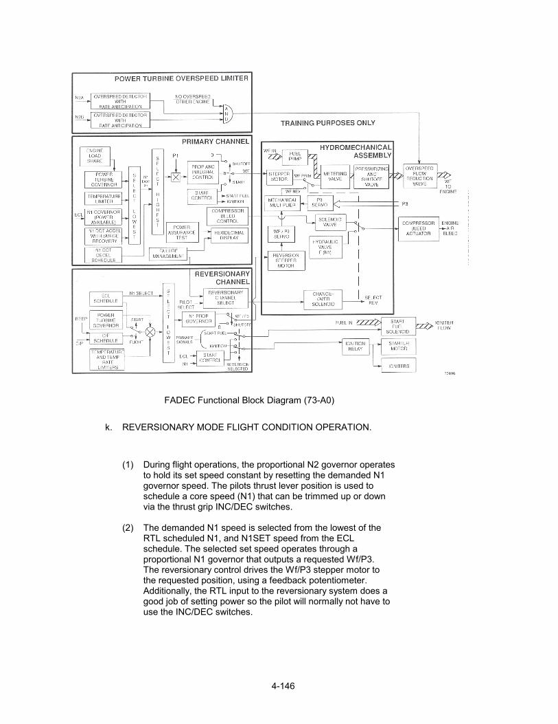
4-146
FADEC Functional Block Diagram (73-A0)
k. REVERSIONARY MODE FLIGHT CONDITION OPERATION.
(1) During flight operations, the proportional N2 governor operates to hold its set speed constant by resetting the demanded N1 governor speed. The pilots thrust lever position is used to schedule a core speed (N1) that can be trimmed up or down via the thrust grip INC/DEC switches. (2) The demanded N1 speed is selected from the lowest of the RTL scheduled N1, and N1SET speed from the ECL schedule. The selected set speed operates through a proportional N1 governor that outputs a requested Wf/P3. The reversionary control drives the Wf/P3 stepper motor to the requested position, using a feedback potentiometer. Additionally, the RTL input to the reversionary system does a good job of setting power so the pilot will normally not have to use the INC/DEC switches.

4-147
a. POWER TURBINE OVERSPEED LIMITER. NOTE: A dual channel analog power turbine overspeed limiter circuit activates a solenoid valve in the event of a power turbine overspeed. (1) When the solenoid valve is actuated, it provides a restriction in the engine fuel supply. (2) The restriction is sized so that approximately 310 PPH will be metered to the engine. (3) Each channel operates using separate pickups N2 A and N2 B. An overspeed condition must be indicated by both channels, and the other engine cannot be currently experiencing an overspeed in order for the solenoid to be activated. (4) Testing the overspeed system is accomplished by a pilot-operated switch which lowers the overspeed trip point to 74.9% of the power turbine speed. The test circuit provides hysteresis that allows the solenoid to open when power turbine speed decreases by 12%. A reduction in core engine speed, and engine fuel flow, provides evidence that the overspeed system is fully operational. The overspeed test is disabled above 81.3% N2.
FADEC Overspeed Test Diagram (ECP D 218) (73-A0)

4-148
b. POWER TURBINE OVERSPEED LIMITER OVERSPEED
SYSTEM OPERATION. (1) The following charts depict a simulated shaft failure and the effect of the overspeed solenoid valve on the engine fuel flow, and power turbine speed. (2) The shaft failure takes place at the one-second mark. The overspeed is recognized and the solenoid is activated within .01 seconds; fuel flow is reduced, the power turbine speed (N2) and core engine speed (N1) both indicate a decrease in RPM. (3) When the power turbine speed begins to rise again, the solenoid is reactivated. This cycle is repeated until the power turbine governor has closed the fuel valve enough to keep the power turbine speed down. (4) At the 2.25 second mark, or 1.25 seconds after the shaft failure the engine is again under control. Also shown in the charts are the fuel flow, core engine speed, and the power turbine speed of the other engine, as it compensates for the sudden loss of power.

4-149
FADEC System Overspeed Protection Performance (73-A0)

4-150
a. POWER ASSURANCE TEST.
(1) The primary control performs a power assurance test when the POWER ASSURANCE TEST switch, which is located AT STA 523, is placed in the 1 OR 2 position. The results are output to the hexadecimal display. The computation uses sensed T4.5, Torque, T1, and P1 to compute the temperature margin. The test fails if the calculated T4.5 is less than the sensed T4.5 temperature.
NOTE:
TEST PROCEDURES Power Assurance Test Power Assurance Check Refer to the operator’s manual for test procedures.
FADEC Functional Block Diagram (73-A0)

4-151
b. FAULT MONITORING PROCESS, PRIMARY MODE.
(1) The fault monitoring process carried out by the DECU consists of power-up, and continuous fault checks. The power-up check is a one time check at aircraft power-up (ECL < 10 degrees, and N1 < 7%), is designed to discover dormant system faults. The process exercises the pressure sensors, bleed valve solenoid, primary reversionary change-over solenoid, watchdog timer circuitry, Programmable Read Only Memory (PROM), and Electronically Erasable Programmable Read Only Memory (EEPROM) logic circuits. At initial power-up, the primary system switchover circuitry (watchdog timer) trip mechanism is exercised and tested for proper operation. All system fault counts are reset to zero at system power-up.
c. CONTINUOUS FAULT CHECKS.
(1) Continuous fault checks are performed during all operating phases, Checking the airframe and engine interface sensors, FADEC system electromechanical components, and the system power supplies. While the continuous fault checks are in-progress on the N1 A, N1 B, thrust control position transducer, N2 A, N2 B, or ECL sensors, a stepper motor position freeze will be enforced, avoiding possible power transients. d. MONITORING FAULT CHECKS. (1) Power-Up Prestart Checks. (2) Presure Sensors. (3) Bleed Valve Solenoid. (4) Primary Reversionary Change-Over Solenoid. (5) Primary Switch-Over (Watchdog Timer) Circuitry. (6) Programmable Read Only Memory (PROM). (7) Electronically Erasable Programmable Read Only Memory (EEPROM). e. CONTINUOUS FAULT CHECKS. (1) Airframe & Engine Interface Sensors. (2) Electromechanical Components. N (3) Power Supplies.

4-152
f. FAULT MONITORING PROCESS REVERSIONARY MODE. (1) Reversionary channel fault checks are continuously conducted during SYSTEM operation. The Reversionary system conducts various operating mode fault checks, including a check of the reversionary channel fault detection circuitry (watchdog timer). The reversionary channel provides a single fault signal to the primary channel. (2) Hard faults will disable the reversionary stepper motor freezing it at the current position. If the reversionary fail signal sensed by the primary channel is continuous, the primary channel ncrements a fault counter and will log a reversionary fault if the count exceeds a preset limit. (3) The rate of change of various input signals is calculated over a two cycle sampling period, using the change between the current cycle and the data from two cycles earlier. (4) If any signal normally transmitted between DECUs has faulted it will not be transmitted. (5) Both the primary and reversionary channels have a hardware watchdog timer that will hard fault the channel if the fault counter exceeds preset limits.
f. REVERSIONARY MODE FAULT CHECKS. (1) Rate Of Change Tests. (2) Signals Transmitted. (3) Between Decus. (4) Fault Circuits.
g. DETECTED FAULT CLASSIFICATION.
NOTE: All detected faults are classified into two main categories. (1) Soft Faults: Are failures that do not impact normal control of the engine or aircraft. Soft faults are not indicated in the cockpit. (2) Hard Faults: Are failures that could cause unacceptable engine and/or aircraft performances if operations were to continue in the degraded mode of control. Hard faults are detected through software fault limit monitoring or if the primary channel software or computer were to fail. The primary system will fail to reversionary through the operation of the watchdog timer. If the watchdog timer, times out or receives a hard fault signal, it will cause the primary/reversionary change-over solenoid, bleed valve solenoid, and primary stepper motor to be de-energized, enabling the reversionary control

4-153
mode. All faults (hard or soft) are logged in an electronically erasable programmable read only memory (EEPROM). Active faults are readable through a two-digit hexadecimal display on the DECU. FAULT CLASSIFICATION. (1) Soft Fault: (a) Failures which will not impair normal mode control of the engine or aircraft. (b) Pilot action NOT required. (c) No cockpit indications. (d) A fault information displayed in the hexadecimal DECU display. (2) Hard Fault. (a) Failures which could seriously impair operation of the engine or aircraft. (b) Primary will fail automatically to reversionary and FADEC 1 (2) indication will be displayed. i. REVERSIONARY HARD FAULT. (1) Reversionary fail fixed REV 1 (2) will be displayed. (2) Primary and Reversionary fail fixed FADEC 1 (2) and REV 1 (2) will be displayed (if primary fails or pilot j. Primary Hard Fault Options. (1) Since normal operation in the primary mode is unacceptable under these conditions, the system is designed to take one of two possible options. (2) Option one - Reversionary System has not failed: In most circumstances, a normal fault free reversionary system will be available as a back up to the failed primary system. In this case the primary system trips the watchdog timer, which results in de-energizing the metering valve primary stepper motor, bleed valve solenoid, and the primary/reversionary change over solenoid. De-energizing the primary/reversionary change over solenoid causes the fuel metering valve position to be controlled by the reversionary channel through the function of the Wf/P3 servo, mechanical multiplier, and P3 servo. The FADEC 1 (2) indication is displayed in the cockpit. (3) Option Two - Reversionary System Hard Fault (REV 1 (2) ON) Automatic switchover to the failed reversionary mode will not occur and due to the primary mode failure the engine is now in the failed fixed condition. FADEC 1 (2) and REV 1 (2)

4-154
will be displayed. (4) If the reversionary mode was selected over a functioning primary system and the reversionary system experiences a hard fault the reversionary stepper motor freezes at its current setting. Since this may not represent the current engine operating condition (primary does not shadow reversionary), the primary system is designed to fail fixed rather than automatically switch to the primary system. The primary mode will have to be selected through the use of the PRI/REV select switch. k. FAULT VERIFICATION AND LOGGING. (1) Signals are checked against high and low limits and where practical against a rate of change limit. Additionally, if the system uses redundant signals (i.e., N1 A and N1 B) the differences between the signals are checked to be within limits. A signal will be determined to have failed when the control has detected and verified a hard or soft failure of the signal. Unless specified otherwise, Verification will be managed by the use of fault counter that increments by two for each computer cycle (24 ms) the signal is outside its limit. The fault count decrements by one count for each cycle where the signal is within its limits, (zero is the minimum count). The count range for the majority of primary channel faults is between zero and eight counts. When the maximum of eight counts is reached, the signal will be classified as either a soft or hard fault and logged in a fault register in the EEPROM. The count range for the majority of reversionary channel faults is between zero and ten counts. When the maximum of ten counts is reached, the signal will be classified as either a soft or hard fault and logged in a fault register in the EEPROM. During cycles where a signal is out of limits and prior to triggering a hard fault, the channel for computation purposes will use it’s last good value. l. SAMPLE FAULT LOGIC (N1). (1) The N1 fault logic provides means to check the high and low range limit on both the N1 A and N1 B signal. Additionally, an N1 A/N1 B difference limit is checked and both signals are limit checked. Note that all fault counters are reset to zero on a power-up to preclude a fault signal due to an errant count. Logic is provided to set the proper low speed fault limit, depending on the operating condition. Normally, N1 A is the speed signal used by the DECU. The fault logic provides for the DECU to select N1 B under specific fault conditions.

4-155
N1 Fault Logic (73-A0)

4-156
m. FAULT STORAGE AND READOUT. (1) Faults are classified as either soft or hard and each has a two-digit hexadecimal (alpha/numeric) identification code. After a fault is confirmed, the fault is logged in EEPROM. The fault display logic determines when the fault code is output to the two-digit hexadecimal display on the DECU housing. The hexadecimal display is available until the ECL is moved past the 55-degree position (the ECL, FLT position is at 60 degrees except for the power assurance test. The most significant character or digit is used to identify the source of the faulty component. Hexadecimal identification codes. (a) F - Fluid Controller (HMU). (b) A - Airframe Sensor. (c) D, 1, or B - DECU. (d) E - Engine Sensor. (e) C - Communications Between the DECUs. (2) The least significant digit is used to identify the specific fault; for example: (a) Display E2 = (E) - Engine sensor, (E2) T1 Sensor. (Soft fault) (b) Display D5 = (D) - DECU, (D5) 15 Volt, (Hard fault). (3) For every fault, a set of procedures is specified to account for the post-fault operation of the control unit. This varies from simply displaying and logging soft faults, to activating the watchdog timer and tripping the control to the reversionary system for hard faults. For primary signals that also have a backup, the fault procedure is simply to use the backup signal source.

4-157
No. Failed Signal
Fault Procedures Fault Class
Identifier Hex. Fault Code
1 T4.5 Set constant = 800ºF Soft Sensor or circuit E1 orB4 2 T4.5 (0) Soft Eng./Eng.
Communication C1
3 N1 A Use N1 B Soft Sensor F1 4 N1 B a)Select N1 A(if N1 A
not faulted) Soft Sensor F2 or B2
b) Revert to reversionary (if N1 A fault exists).
Hard Sensor
5 N1 A/N1 B Diff.
Use highest value sensor
Soft Sensor F3
6 P3 Use constant =120 psi Soft Sensor D1 7 P1 Use P1 (0) Soft Sensor D2
No change if using P1 Soft 8 P1 (0)
Reversionary if P1 fault
Hard
Eng./Eng. Communication
C2
9 T1 Use T1 (0) Soft Sensor E2 No change if using T1 Soft 10 T1 (0)
Reversionary if T1 Fault
Hard
Eng./Eng. Communication
C3
11 Q Disable load sharing Soft Sensor A1 12 Q (0) Disable load sharing. Soft Eng./Eng.
Communication C4
Table 1 Primary Fault Identification Codes (Sample)
n. REVERSIONARY FAULTS. (1) The reversionary system has four discrete output signals to provide signal fault status to the primary channel for output on the fault code display (reversionary mode faults are not displayed directly on the fault display). The four signals will represent a four bit binary number that corresponds to a fault code (0-15). Four zeros indicate that there are no reversionary system faults. If all four signals are 1, the Indication is the reversionary system has failed fixed. In this case, the primary system will not trip the watchdog timer for automatic switchover to the reversionary mode. Under these conditions, the primary system will freeze its stepper motor by holding the primary stepper in the fixed position. Both the FADEC 1 (2) and REV 1 (2) indications wil be on. Engine control consists of shutting down the engine, using the engine fire pull handle.

4-158
Fault Limits Signal High Low Conditions
Failure Action Fault Code to Prim.
N1 B 120% 30% If (ECL >23% and run mode* and N2 > 50%) or (run mode and (last valid N1 B value – current in-put value –30%))
Hold last good value of N1.set WF/P3 = WF/P3
1
N2 B 170% 10% If N1 > 80% Set N2 = 100% for control use. (System continues operation without power turbine governor).
2
T4.5 1850º F 250º F N1> 50% no low limit test if N1 < 50%
Set T4.5 = 0ºF for control use.(system continues operation without T4.5 limiting)
3
RTL 95.0% -4.0% All Fix WF/P3* = WF/P3 4 ECL 64.5 -4.0 Hold 2nd last good value
of ECL. (Normal flight operation but cannot shutdown in reversionary). If failed on power up set =30 degrees.
5
PLA 107.5º -6º If not power-up, use step count backup. If power-up freeze stepper.
6
*Run mode defined as NOT Start (REV) Mode and NOT Shutoff Mode. Table 2 Reversionary Fault Identification Codes (Sample)* o. ENGINE FAILURE DETECTION. (1) Failure logic recognizes four different engines failed conditions: (a) Power absorber shaft failure, = N2 >NR 3%. (b) Gas producer turbine under-speed, = N1 < 48%. (c) Engine flameout, = N1 DOT < N1 DOT minimum. (d) Start abort. NOTE: Should any of these conditions occur, the ENG 1 (2) FAIL indication is displayed on the Caution panel.

4-159

4-160
T55-L-712F/55-L-714A ELECTRONIC TORQUEMETER FLIGHT LINE TEST SET LTCT 30566-01/03
Figure FLTS LTCT 300566-01/03.
OPERATION The FLTS performs four functions to an aircraft torquemeter system as described below. AIRCRAFT SYSTEM TEST This FUNCTION SELECTOR position allows the operator to tap into and monitor aircraft system parameters under normal operating conditions.

4-161
Figure Aircraft System Test interconnect Digram

4-162
Figure Aircraft System Test
AIRCRAFT RDPS This FUNCTION SELECTOR position allows the operator to tap into and monitor the aircraft Ratio Detector Power Supply (RDPS) signals, using the FLTSs internal torque simulator, J-Box, and signal conditioning network.

4-163
Figure Aircraft RDPS Test

4-164
INTERNAL J-BOX REFERENCE SIGNATURE This FUNCTION SELECTOR position provides readouts for the reference FLTS internal torque simulator, J-Box, and signal conditioning network. EXTERNAL J-BOX SIGNATURE This FUNCTION SELECTOR position will allow the operator to establish J-Box characteristics and perform a J-Box replacement using the FLTSs internal torque simulator.
Figure Determine J-Box Signature
.

4-165

4-166

CHAPTER 5
ROTOR SYSTEM
ROTARY-WING HEAD AND CONTROLS
DESCRIPTION AND OPERATION
5-1

ROTARY-WING HEAD AND CONTROLS
This rotary-wing head transmits torque from theforward or aft transmission rotor shafts to therotary-wing blades. The rotary-wing controlstransmit cockpit control movements to the blades.Three rotary-wing blades are attached to both theforward and aft rotary-wing heads. The aft bladesturn clockwise and the forward blades turncounterclockwise, when viewed from above. Eachrotary-wing head and controls consists of a rotorhub, three pitch-varying housings, three pitch-varying shafts with droop stops, three shockabsorbers, a swashplate, three pitch links, a drive
and bearings are secured by locking beams, Thebeams connect the Ieading cap of one pin with thetrailing cap of the next pin.
PITCH-VARYING HOUSINGS
The pitch-varying housings are connectedInternally to pitch-varying shafts by flexible, la-minated steel tie bars. The Iaminated tie barallows the pitch housing to rotate on the pitchshaft to change blade pitch. The tie bar is con-nected to the inboard end of the pitch shaft. Thepitch arm on each housing is connected by a pitch
collar and drive arms, and a weather-protective link to a lug on the swashplate. The pitch linkcover. raises or lowers the pitch arm to rotate the hous-
ROTOR HUBing on two roller bearings on the shaft. Outboardlugs on the housing contain bearings for the
The rotor hub contains splines that mate with vertical hinge pin.splines on the transmission rotor shaft. Pitchshafts are connected to the hub through the threehorizontal pins. These pins ride in bearings sup-ported by the hub lugs. Caps retaining the pins
5-2

ROTARY-WING HEAD AND CONTROLS (Continued)
DROOP STOPS
The droop stops limit blade droop. Each pitch-varying housing is supported by a droop stop. For-ward and aft heads have fixed droop stops. Theseare installed on the bottom of the pitch shaft tolimit droop at zero rotor speed. These fixed droopstops rest directly against the hub. The centrifugaldroop stop assembly is mounted on a splined plateunder the aft rotor head. The droop stop containsthree balancing arms. These are connected by spr-ings to lugs on the hub oil tank. Interposer blockson the balancing arms are positioned betweenfixed blocks and the hub. As rotor speed increases,the centrifugal droop stops swing out. This movesinterposer blocks clear of the pitch shafts and
allows more freedom for blade droop. As rotorspeed decreases, the springs pull the arms intoward the hub. This positions the blocks betweenthe hub and pitch shafts to reduce droop angle.
SHOCK ABSORBERS
Each head has three shock absorbers. They areconnected between lugs on the pitch-varyinghousing and brackets on the blades. The shockabsorbers limit lead and lag motion of the blades.Each shock absorber has a vent valve. The valve isopened for extreme cold weather operation.Changing the vent valve position allows the shockabsorber to be used on forward or aft head.
5-3

ROTARY-WING HEAD AND CONTROLS (Continued)
SWASHPLATES
The forward and aft swashplates transmit manualor automatic cockpit control movements to therotary-wing blades. The swashplates can be tiltedand moved vertically. This movement is transfer-red to the blades through the pitch links and pitch-varying housings. Forward and aft swashplateshave aluminum rotating rings. The stationary ringon the aft swashplate is steel. On the forwardswashplate this ring is aluminum. The stationaryring of each swashplate is mounted on a sphericalbearing. This allows the swashplate to tilt in anydirection. A ball bearing connects rotating and sta-tionary rings. The swashplate is free to slide up ordown on a slider shaft to change blade pitch
the rotating ring can be used on forward or aftswashplate. Lugs on the stationary ring provide forconnection of two servocylinders, fixed link, andIogitudinal cyclic trim actuator. Two single inter-rupters and a double interruptor on the rotatingring, and a magnetic pickup on the stationary ring,are used for rotor balancing.
PITCH LINKS
The six pitch links are connected between theswashplates and pitch-varying housings. Tilting aswashplate up or down moves the pitch link andpitch arm in the same direction. This increases or
angle. Lugs are provided on the rotating ring for decreases the blade pitch angle. Raising or lower-
connecting three pitch links and an upper drive ing the swashplate on the slider shaft changes
arm. Drive arm lugs are located in two positions so pitch on ail three blades.
5-4

ROTARY-WING HEAD AND CONTROLS (Continued)
Three pitch links are installed on each rotary-winghead. Forward and aft pitch links are similar ex-cept for the angle between rod ends. Each pitchlink is adjustable to change the pitch of an indi-vidual blade. Moving the turnbuckle toward the +mark makes the pitch link longer and increasesblade pitch. A turn in the – direction shortens thepitch link and decreases blade pitch.
DRIVE COLLAR AND DRIVE ARMS
The drive collar transmits torque to the swash-plate through the upper and lower drive arms. Thedrive arms are hinged to allow the swashplate toslide up and down on the slider shaft. The splineddrive collars mate with splines on the transmissionrotor shafts. A flange is located on the drive collar
for installation of the weather-protective cover.Drive collar lugs are provided for connecting theupper drive arm. The upper drive arm is connectedat the other end to the lower drive arm. Both con-nections are hinged. A ball spherical bearing onthe lower drive arm is connected to the swash-plate. This arrangement allows swashplate to tilt.
WEATHER-PROTECTIVE COVER
The weather-protective cover is bolted to the drivecollar flange and turns with the collar and shaft.The cover provides weather-protection for the up-per controls. Flexible boots protect the upper por-tion of the pitch links where they pass through thecover.
5-5

ROTARY-WING HEAD AND CONTROLS (Continued)
LUBRICATION SYSTEM SELF-RETAINING BOLTS
A single hub oil tank lubricates the horizontal pin Bolts connecting upper controls and shock
bearings. Each pitch-varying housing has a pitch absorbers are the positive-retention or impedance
bearing oil tank and two vertical pin bearing oil types. These bolts have a pawl or lock ring to keep
tanks. The vertical pin tanks are connected to each the bolt in place, even with the nut removed. Bolts
other by an oil manifold tube. Sight indicators are are installed with bolt heads facing the direction of
provided for each tank, to check oil level. The rotation (Task 1-14).
swashplate is lubricated with grease.
5-6

Rotor System
A. Rotor System Improvements
1. Vertical Hinge Pin Oil Tanks
a. Composite material
b. All tanks upper and lower interchangeable
2. Vertical Pin Oil Transfer Tube
3. Positive Locking for Horizontal Hinge Pin Cap
4. Position Retention Hub Nut
5. One Piece Drive Collar
6. Impedance Bolts Instead of Positive Retention Bolts
7. Fiberglass Rotor Blades
8. Lateral Balancing Capabilities - RADS-AT
9. Larger Bearing on Shock Absorbers
B. Description
1. Rotor Head and Rotor Head Controls
Lift is produced by a rotor system consisting of two fully articulated counter-rotating rotors.Each rotor has three fiberglass blades. The forward rotor is driven by the forward transmissionthrough a rotor drive shaft. The aft rotor is driven by the aft transmission through a verticaldrive shaft. The rotor head consists of a hub connected to three pitch-varying shafts by threehorizontal hinge pins. These pins permit blade flapping. Stops on the top and the bottom ofthe hub limit the blade flapping motion. The aft rotor head is equipped with centrifugal droopstops which provide increased blade flapping angle for ground and flight operation. Covers areinstalled on the centrifugal droop stop operating mechanism. The covers prevent iceaccumulation on the mechanism and ensures proper droop stop operation following flight inicing conditions. Mounted coaxially over the pitch-varying shafts are pitch-varying housings towhich the blade leading and lagging. Each pitch-varying shaft is connected to the pitch-varyinghousing by a laminated tie bar assembly. The high tensile strength and low torsional stiffnessof the tie bar retains the blade against centrifugal force and allows blade pitch changes aboutthe pitch axis. Blade pitch changes are accomplished by three pitch-varying links connectedfrom the rotating ring of the swash plate to the pitch-varying housing on each rotor blade.Cyclic pitch changes are accomplished by tilting the swash plate. Collective pitch changes arerealized by vertical movement of the swash plate. Combined collective and cyclic pitchchanges result from combined control inputs by the pilot. A direct action shock absorber isattached to the blade and to the pitch-varying housing. When the inboard end of the shockabsorber is disconnected, the blade can be folded in either direction about the vertical hingepin.
5-7

a. Specification - Rotor Heads
(1) Weight: Forward: 642.0 pounds
Aft : 664.0 pounds
(2) Dimensions, forward and aft: 15 in. high: 35 in. dia.
(3) Type of Lubricating Oil: MIL-L-7808
(4) Reservoir Capacity: Quarts
(a) Pitch varying housing and oil tank 0.44
(b) Rotary wing hub and oil tank 1.07
(c) Vertical hinge pin bearings and oil tank 0.62
b. Specifications - Swash plates
(1) Weight: Forward: 212.0 pounds
Aft: 333.0 pounds
(2) Dimensions: Forward: 40 in. long: 36 in. wide: 23 in. high
AFT: Same dimensions
(3) Rotary wing head controls cover
(a) Weight: 21.0 pounds
(b) Dimensions: 8 in. high: 40 in. dia.
2. Fiberglass Rotary Wing Blade
a. Location
(1) Three rotary wing blades are attached to
(a) The forward rotary wing head
(b) The aft rotary wing head
(2) Access to the rotary wing blades is made by positioning each blade over the cabincrown walkway.
(3) Forward and aft work platforms will be opened for access to the blade attachingpoints.
b. Function
(1) The rotary wing blade provides lift (thrust). Cockpit induced flight control inputs willchange blade incidence to enable varying flight attitude and direction changes.
5-8

c. Specifications
(1) Weight: 357.0 pounds
(2) Dimensions: 330.5 in. span; 32 in. chord; 6 in. high
(3) Radius of Rotation: 360.0 ins.
d. Construction
(1) The fiberglass rotor blade presents a number of advantages over the metal blade.
(a) Fiberglass is non-corrosive
(b) Crack propagation is considerably slower due to the characteristics of thefiberglass composition.
(c) A significant improvement is surviving ballistic damage.
(d) The provisions for vibrex balancing are incorporated into the blade.
(2) The fiberglass rotor blade is a composite fiberglass, titanium and nomex coreassembly.
(3) The main structural component is a D-shaped fiberglass spar.
(a) Leading edge elements are bonded to the front of the spar.
(b) A fairing assembly of nomex core with fiberglass covering is bonded to thetrailing edge of the spar.
(4) The "D" spar structural elements consist of:
(a) Center and wrap around tension straps of unidirectional fiberglass thatextend from the root, looping around the retention pin bore, to the tip.
(b) The straps are covered by multiple layers of cross-ply fiberglass to providetorsional stiffness.
(5) A composite kevlar shock absorber attaching bracket is bonded to the spar near theroot end by Kevlar filament windings.
(6) A composite fiberglass sleeve lines the retention pin bore. Wear pads are bondedto the spar above and below the sleeve installation.
(7) The leading edge of the spar is covered by a titanium nose cap.
(8) A nickel erosion cap is bonded to the outboard 54 inches of blade tip.
5-9

(9) The fairing assembly consists of nomex honeycomb core covered with a skin ofcross ply fiberglass laminates.
(a) The leading edge of the core and the fiberglass skin is bonded to the trailingedge of the spar.
(b) The trailing edge of the fairing assembly is reinforced by a wedge ofunidirectional fiberglass that extends the entire span of the fairing assembly.
(c) The inboard end of the assembly is sealed with a Buns-N rubber closure rib.
(d) A stainless steel tip cover closes the forward outboard end of the blade.Buns N rubber sealant covers the end of the blade aft of the tip cover.
(e) A stainless steel trim tab is bonded to the trailing edge outboard of Station239.
(10) Located in and aft of the spar at the outboard end, are the production trackingweights, which are used to establish chord and span production balancing.
(11) Ten vibrex balancing weights are attached to the tip cover along the pitch asixcenterline. 81-TA-4048B
(12) Lightning protection is provided by aluminum wire mesh molded into the fiberglassskin at the blade tip and trim tab areas.
(a) A lightning protection strip extends from the inboard end of the titanium capto the bonding cables attached to the rotary wing head.
(b) A splice strap bridges the gap between the protection strip and the titaniumcap. This strip will unbound in the event of a lightning strike and indicates arequirement for blade lightning damage investigation.
(c) The titanium cap provides an electrical path from the wire mesh to theprotection strip and bonding jumpers.
(d) Accelerometer blocks, installed at the forward rotor, Station 75, WL 40, BL12L, and aft rotor, Station 590, WL 122, BL 10R, send a signal to thebalancer.
5-10

CHAPTER 6
DRIVE SYSTEM
DRIVE SYSTEM
DESCRIPTION AND OPERATION
6-1

TRANSMISSION
A. CH-47D Power Train System Improvements
1. 7500 HP @ 15.066 Engine RPM
2. All shafts free floating at transmission inputs
3. Integral lubrication systems
4. Auxiliary lubrication systems
5. Pressure and temperature switches added
6. Indicating debris screens added
7. Kevlar sumps on rotor and combiner transmissions
8. AGB deleted - direct assembly drive
9. Spare 12,000 RPM drive pad aft transmission
10. Hydraulic pump drive pad on forward transmission
B. Presentation
1. General Description
a. The power train system in the CH-47D consists of five transmissions and their associateddrive shafts.
b. The transmissions are:
(1) Two engine transmissions
(2) One combining transmission
(3) One forward rotor drive transmission
(4) One aft rotor drive transmission
c. The drive shafts are:
(1) Two engine transmission quill shafts
(2) Two engine drive shafts.
(3) Seven forward synchronizing shafts
(4) Two aft synchronizing shafts
(5) One forward vertical drive shaft (part of the forward transmission)
(6) One aft vertical drive shaft
6-2

d. Each transmission has an independent oil lubrication system that is air cooled through aheat exchanger.
e. System condition monitors for oil pressure, temperature, and chip detection are found ineither the cockpit master caution panel, the cabin maintenance panel, or the oil pressureand temperature indicators mounted on the cockpit instrument panel.
f. The aft transmission accessory section drives the No. 1 and No. 2 AC generators, theutility system hydraulic pump, the No. 2 flight controls hydraulic pump, the main oil pumpand the cooling fan.
g. The drive system distributes the torque delivered by the two engines to the forward andaft rotary wing blades.
h. The reduction in gear ratio between the engine and 82-TA-4593A rotary wing blades is66.96:1.
6-3

TRANSMISSION 1
TRANSMISSION DRIVE
1. Description
Transmits engine torque to the two rotor heads via transmissions and drive shafts.
2. Engine Transmission
a. Purpose
The engine transmissions are attached to the forward end of each engine. Power from eachengine is supplied to the respective transmission by way of a quill shaft, which drives the spiralbevel pinion gear. The spiral bevel pinion gear drives the spiral bevel gear and shaft assemblywhere the direction of torque is changed approximately 90 degrees. A speed reduction of1.23:1 occurs within the engine transmission.
Torque is transmitted by the engine shafts from the engine transmissions to the combiningtransmission.
The two engine transmissions are identical and can be used in either position by making aminor mechanical conversion.
b. Over-riding Sprag Clutch
Torque is then transmitted through a one-way drive, overriding (sprag) clutch to the outputshaft. The sprag clutch permits the rotary-wing system to override the engine during auto-rotation or in the event of an engine failure.
3. Combining Transmission
a. Purpose
The combining transmission receives the torque delivered from both engine transmissions anddistributes the combined torque to the forward and aft transmissions.
The torque from both engines is combined within the transmission by means of two spiral bevelinput pinion gears and a single spiral bevel ring gear. The spiral bevel input pinion gearsreceive the torque from the engine transmissions and both gears drive the ring gear. A speedreduction of 1.77:1 occurs at this point. The ring gear is bolted to the aft drive shafts throughforward and aft combiner output shafts. These output shafts are connected by a bearingmounted splined coupling.
6-4
4. Forward Transmission
a. Purpose
The forward rotor drive transmission transmits torque from the combining transmission to therotary-wing head. Torque is transmitted within the transmission by a spiral bevel input piniongear, which meshes with a spiral bevel ring gear. At this point, the direction of torque ischanged from a horizontal to a vertical plane. The ring gear is bolted to the first stage sungear. The sun gear, in turn, drives the first stage planet gears which mesh with a Stationaryring gear.
The non-rating ring gear causes the planet gears to revolve around the sun gear. The planetgears are attached to the first stage carrier which also revolves around the sun gear. Theupper portion of the first stage carrier forms the second stage sun gear and it drives the secondstage planet gears. These planet gears are attached to a second stage carrier and revolve inthe same manner as the first stage planet gears and carrier.
The second stage carrier is an integral part of the rotor shaft, which is externally splined at thetop to receive the forward rotary-wing head.
Three stages of speed reduction take place during the transmission sequence. The resultingoverall reduction ratio is 30.72:1.
b. Hydraulic Pump
The No. 1 flight control hydraulic pump is mounted on and driven by the forward transmission.
c. Rotor Tachometer
The copilot rotor tachometer receives its indication signals from No. 1 generator permanentmagnet section and the pilot from the No. 2 generator. Indicator power is provided by the No. 1and No. 2 dc buses respectfully.
5. Aft Transmission
a. Purpose
The aft rotor drive transmission transmits torque from the combining transmission to the aftrotary-wing head. The torque is transmitted within the transmission by a spiral bevel ring gear.At this point, the direction of torque is changed from a horizontal to a vertical plane, and thedirection of drive is opposite to the forward transmission. The ring gear is bolted to the firststage sun gear. The sun gear, in turn, drives the first stage planet gears, which mesh with aStationary ring gear.
The non-rotating ring gear causes the planet gears to revolve around the sun gear. The planetgears are attached to the first stage carrier, which also revolves around the sun gear. Theupper portion of the first stage carrier forms the second stage sun gear and it drives the secondstage planet gears. These planet gears are attached to a second stage carrier and revolve inthe same manner as the first stage planet gears and carrier.
6-5

The second stage carrier is splined to receive the aft rotary-wing (vertical) drive shaft. The topof the aft vertical drive shaft is splined to receive the splines in the aft rotary-wing head.
Three stages of speed reduction take place in the aft transmission, the same as in the forwardtransmission. The resulting overall reduction ratio is also 30.72:1.
b. Accessories Driven by the Aft Transmission
(1) Two ac generators, the No. 2 flight control hydraulic pump, and the utility system pumpare mounted on and driven by the aft transmission.
6. Engine Drive Shafts
a. Purpose
The engine shaft assembly includes an engine shaft, and engine transmission adapter, acombining transmission adapter, and two flexible coupling packs.
The assembly transmits torque from each of the engine transmissions to the combiningtransmission. Each shaft is connected to the combining transmission. Each shaft is connectedto the combining transmission and engine transmission by an adapter and plate assembly.
The shaft assemblies are serial-numbered and dynamically balanced as a unit. A hingedfairing encloses each shaft between the engine transmission fairing (bullet nose fairing) and thepylon.
7. Forward Sync Shafts
The forward sync drive shaft transmits torque from the combining transmission to the forward rotary-wing transmission. It also keeps the forward and aft rotors mechanically connected and in phase witheach other.
This sync shaft extends from the combining transmission to the forward transmission and consists ofseven sections of shafting (No. 1 through No. &), eight flex coupling splined adapter assemblies, andeight flexible plate packs. The shaft is supported by 6 bearing support assemblies placed betweenthe forward and combining transmissions. The assemblies are interconnected by means of theadapter and flexible plate assemblies.
Shaft sections are located externally along the fuselage crown at water line +56.00, provided byhinged and removable covers along the top of the fuselage.
6-6

8. Aft Sync Shaft
The aft sync shaft transmits torque from the combining transmission to the aft rotary-wing drivetransmission and consists of 2 sections. They are located in the aft fuselage section at waterline+56.00. The No. 8 section is connected to the aft end of the combining transmission. The No. 9section is connected to the aft rotary-wing drive transmission by a flex pack and adapter. The shaftand adapter are balanced as an assembly and are marked by an index and serial number. The twoshafts are connected in the center by an adapter and flex coupling plate assembly, which issupported by a bearing support assembly and support structure.
9. Forward Vertical Drive Shaft
The forward vertical drive shaft assembly extends upward through the forward pylon. It transmitstorque from the forward rotary-wing drive transmission to the forward rotary-wing head and isintegrally forged with the second stage planetary carrier in the forward transmission.
10. Aft Vertical Drive Shaft
The aft vertical drive shaft assembly extends upward through the aft pylon. It transmits torque fromthe aft rotary-wing drive transmission to the aft rotary-wing head. The base of the shaft is splined tomatch the splines of the aft transmission. The upper section of the shaft is splined to match thesplines of the aft rotor head.
A thrust bearing and a housing, which is bolted to the canted deck at waterline +119.8, supports theshaft. The bearing is lubricated by oil from the aft transmission lubrication system. The slider shaft ismounted over the drive shaft and secured to the housing assembly.
6-7

A. Description - Transmission Lubrication Systems
The forward, aft, and combining transmissions each include independent main and auxiliarylubrication systems which operate concurrently. Refer to TM 55-1520-240-10, Table 2-3, page 2-75for transmission oil system capacities, oil specifications, and servicing procedures.
1. Forward Transmission
The forward transmission lubrication system supplies lubricating oil to the gears and bearings inthe forward transmission. Main system oil flows from the sump, through the main oil pump, oilfilter, cooler, and a jet protection screen to jets from which the oil is discharged to the variousgears and bearings. Auxiliary system oil flows from the auxiliary sump through the auxiliary oilpump, and the auxiliary system filter to separate AUX OIL jets. The main system filter has animpending bypass indicator. The bypass indicator extends if the pressure drop across the filterexceeds 15 to 18 psid, which may indicate a partially clogged filter. An oil cooler mounted onthe aft end of the transmission around the input pinion cools main system oil. Air is forcedthrough the cooler by a transmission-driven fan. Oil capacity 27.9 quarts.
2. Aft Transmission
The aft transmission lubrication system supplies lubricating oil to the various gears andbearings in the aft transmission and to the aft rotor shaft bearing. In addition, the mainlubrication system circulates cooler oil through the two ac generators on the aft transmission.Transmission oil flows from the sump through the main lube pump, main filter, cooler, and thejet protection screen to jets where the oil is sprayed onto the various gears and bearings. Inaddition, after the oil leaves the jet protection screen, alternate paths route some of thelubricating oil to the aft shaft bearing and cooling oil to the generators. Auxiliary system oilflows the auxiliary sump through the auxiliary pump and filter to the various gears and bearings.Separate oil jets are utilized for each oil system. The auxiliary system does not lubricate the aftshaft bearing or the generators. An oil cooler mounted on the aft end of the transmission coolsmain system oil. Cooling air is drawn through the cooler by a transmission-driven fan. Themain system filter has an impending bypass indicator. The bypass indicator extends if thepressure drop across the filter exceeds 15 to 18 psid, which may indicate a partially cloggedfilter. Oil capacity 43 quarts.
3. Combining and Engine Transmission Lubrication Systems
Combining transmission oil flows from the sump through the main pump, main filter, cooler, andjet protection screen to the various gears and bearings. Auxiliary system flows from theauxiliary reservoir through the auxiliary pump and auxiliary filter to the various gears andbearings. Separate oil jets are utilized for each oil system. Two scavenge pumps return the oilto the reservoir from the transmission sump. The combining transmission filter has inimpending bypass indicator. If the pressure drop across the filter exceeds 15 to 18 psid, thebypass indicator will extend. This may indicate a partially clogged filter. Engine transmissionoil flows from the reservoir through the pump, filter, cooler, and jet protection screen to the jetswhich spray the oil onto the various gears and bearings. A scavenge pump returns the oil fromthe transmission sump through in indicating screen and back to the reservoir. Enginetransmissions do not have auxiliary lubrication systems. All engine transmission lubricationsystem components, except the jet protection screens and jets are on the combiningtransmission. The engine transmission filter has an impending bypass indicator. If thepressure drop across the filter exceeds 15 to 18 psid, the bypass indicator extends, which mayindicate a partially clogged filter. The individual oil coolers for the combining and both enginetransmission drive fan for cooling air. Oil capacities combining transmission 19 qts., enginetransmission 11.1 qt.
6-8

4. Transmission Oil Pressure Indicating System
a. Transmission Main Oil Pressure Indicator
A transmission main oil pressure indicator on the center section of the instrument panel,indicates either the lowest main oil pressure in any one of the transmissions or only theoil pressure in the transmission selected by the pilot. The indicator is electricallyconnected to each transmission. AC power (115-volt) operates this unit. A circuitbreaker for the indicator is on No. 1 power distribution panel and is marked XMSN OILPRESS. Each transmission and aft rotor shaft bearing also incorporates a separate lowpressure switch. These switches are connected to the XMSN OIL PRES caution light.
b. Transmission Main Oil Pressure Selector Switch
A transmission oil pressure selector switch is on the center section of the instrumentpanel. The switch positions are TEST, SCAN, FWD, AFT, MIX, LEFT, and RT. Whenthe switch is set to TEST, the pointer on the transmission pressure indicator will drop tozero or below. In addition, the TEST nomenclature on the switch will be lighted. Whenthe switch is set to SCAN, the SCAN nomenclature on the switch will be lighted and thelowest main oil pressure among all the transmission will be indicated. The nomenclaturefor that transmission will also be lighted. The remaining positions are used to select aparticular transmission oil pressure indication. The nomenclature also lights when atransmission is individually selected. When selecting a particular switch position, be surethe switch is in detent. If the switch is not in detent, the pressure gage will indicate zero.
5. Transmission Main Oil Temperature Indicating System
a. Transmission Main Oil Temperature Indicator
A transmission oil temperature indicator on the center section of the instrument panelreads from -70° to +150°C. It indicates the highest oil temperature among all thetransmissions or only the oil temperature of the selected transmission. Wires connect theindicator and amplifier to a temperature probe in the forward and aft transmission sumpsand in each compartment of a three-compartment oil tank for the combining transmissionand each engine transmission. The temperature probes in the three tank compartmentsmeasure oil temperature in the tank and may not immediately indicate a transmissionproblem. Loss of oil or low oil pressure may not be accompanied by a high oiltemperature indication. Power to operate this unit is supplied by No. 1 115-volt ac busthrough a circuit breaker marked XMSN OIL TEMP on No. 1 power distribution panel.Each temperature probe incorporates a high oil temperature switch which is independentof the temperature indicator and is triggered at 140°C, lighting the XMSN OIL HOTcaution light.
6-9

b. Transmission Main Oil Temperature Selector Switch
A transmission oil temperature selector switch is on the center section of the instrumentpanel below the transmission oil temperature indicator. The switch positions are TEST,SCAN, FWD, AFT, MIX, LEFT, and RT. When the switch is set to TEST, the pointer onthe transmission oil temperature indicator deflects full scale toward low temperature. Inaddition, the TEST nomenclature on the switch will be lighted. When the switch is set toSCAN, the SCAN nomenclature on the switch will be lighted. The highest oil temperatureamong all transmissions is indicated, and the nomenclature for that transmission will belighted. The remaining positions are used for selecting a particular transmission oiltemperature indication. The nomenclature also lights when a transmission is individuallyselected. When selecting a particular switch position, be sure the switch is in detent. Ifthe switch is not in detent, the oil temperature indicator will indicate --70°C.
6. Transmission Warning Lights
a. Transmission Oil Caution Lights
Five transmission oil caution lights are on the master caution panel. The lights aremarked XMSN OIL HOT, XMSN OIL PRESS, XMSN AUX OIL PRESS, and No. 1 andNo. 2 ENG XMSN HOT. These lights, in conjunction with the transmission oil pressureand temperature indicators on the instrument panel alert the crew to impendingtransmission lubrication problems. The caution lights operate independently of thepressure and temperature indicators on the instrument panel. The XMSN OIL HOT lightcomes on when the main oil temperature in the reservoir of the forward, aft, combining, oreither engine transmission exceeds 140°C. The hot transmission is identified by the oiltemperature selector switch and indicator.
The XMSN OIL PRESS caution light comes on when main oil pressure drops below 20psi in any transmission or aft rotor shaft pressure drops below 10 psi. The low-pressuresystem is identified by the transmission oil pressure selector switch and indicator on theinstrument panel. If the XMSN OIL PRESS caution light comes on and the affectedtransmission cannot be determined using the selector switch, the condition may becaused by loss of aft rotor shaft oil pressure. Low oil pressure at the aft rotor shaft isindicated by the illumination of the AFT SHAFT light on the maintenance panel.
6-10

The XMSN AUX OIL PRESS caution light, which is activated by individual aux oilswitches, comes on when auxiliary oil pressure drops below 20 psi in the fwd or afttransmission and 10 psi in the combining transmission. The transmission with the lowpressure is identified by a lit AUX OIL PRESS indicating light on the maintenance panel.
The No. 1 and No. 2 ENG XMSN HOT caution lights come on if oil temperature in eitherengine transmission exceeds about 190°C. The lights are turned on by a thermo switchin each engine transmission. The thermo switch monitors oil temperature in thetransmission, not in the reservoir. The thermo switch is part of a chip detector andtemperature assembly in each engine transmission.
b. Transmission Chip Detectors
Chip detectors are installed in all transmission and aft rotor shaft thrust bearinglubrication systems. All chip detectors, except those in the engine transmission, areconnected to the XMSN CHIP DET caution light on the master caution panel. Enginetransmission chip detectors are connected to the ENG CHIP DET caution lights. Alltransmissions and the aft rotor shaft chip detectors are also connected to theTRANSMISSION CHIP DETECTOR indicators on the maintenance panel. When a chipdetector is bridged by ferrous particles, the XMSN CHIP DET, or ENG CHIP DET cautionlight comes on. At the same time, the corresponding TRANSMISSION CHIPDETECTOR indicator on the maintenance panel will trip and change from an all-blackindication to a black-and-white indication, identifying the transmission.
c. Transmission Debris Screens
There are six TRANSMISSION DEBRIS SCREENS latching indicators on thetransmission section of the maintenance panel. There is one indicator for the forward,aft, and both engine transmission and two indicators marked LH and RH for thecombining transmission. If the screen mesh is bridged by conducting debris, thecorresponding DEBRIS SCREEN indicator will trip. The indicator display will changefrom all-black to black-and-white to indicate possible transmission componentdeterioration.
B. Presentation
1. Transmission
a. Engine Transmission Assembly
(1) Location
(a) An engine transmission is attached to the front of each power plant, in theaft pylon area, centering on Station 463, WL66, BL48R, and BL48L.
(b) Access to the engine transmission is made after the following is removed:
6-11

1 The engine air inlet screen
2 The engine transmission fairing
3 The engine drive shaft fairing
3 The engine drive shaft
(c) Oil Filler and Sight Gage Access
1 Engine and combining transmission. The oil filler and sight gages forthe RH and LH engine transmissions and the combining transmissionare accessible when the aft pylon leading edge fairings are opened.
a The oil filler is located on the combining transmission cover,Station 455, WL76, BL 0. The single filler services the RH, LH,engine transmission and the combining transmission sections ofthe reservoir. They are interconnected at the sight gage level.
b The sight gages for the RH, LH, engine transmissions, and thecombining transmission, are located at identical levels in thecombining transmission reservoir. The combining transmissionsight gage is at the front of the reservoir, the right and left enginetransmission sight gages on the side of the reservoir, facing therespective transmission.
(2) Function
(a) The engine transmission, bolted to the engine air inlet housing, receivesengine torque, changes the drive direction 90°, and transmits the torquethrough the engine drive shaft to the combining transmission.
(3) Specifications
(a) Weight: 128.0 pounds (each)
(b) Dimension: 19 in. long; 16 in. wide; 16 in. high
(c) Type of Lubricating Oil: MIL-L-7808
(d) Reservoir Capacity: 6 quarts
6-12

(e) System Capacity: 11.1 quarts
(f) Transmission Oil Pressure
PSI Minimum PSI Minimum PSI Normal
Ground Idle Operation
Main Sys Aux Sys Main Sys Aux Sys Main Sys Aux Sys
7 - 20 - 20-90 -
Maximum °C
(g) Transmission Oil Temperature 140°C (284°F) (at reservoir)
(190°-207°C) (375°-405°F)(at transmission)
(h) Temperature Warning
1 Transmission oil temperature switch closes at:190° - 207°C
2 Reservoir oil temperature switch closes at:
135° - 145°C
(i) Lubrication Pump
1 Rated speed: 60002 RPM at 100% RPM
2 Rated flow (GPM): PRESSURE SCAVENGE 6.0 18.0
(j) Lubrication Filter 30 Microns
1 Adjustable valve set to: 65 psi
2 Range of adjustment: 45-85 psi
3 Filter bypass valve operates when total pressure drop exceeds: 25-30psid
4 Impending bypass indicator button extends when pressure differentialacross element exceeds: 15-18 psid
Thermonic lockout prevents indicator button activation if, or below:115° +10°F (46° +5°C)
6-13

(k) Oil Cooler
1 Rated oil flow: 14 gpm
2 Temperature/pressure bypass valve
a Redirects oil to bypass cooler core when outlet temperature is:160° +10°, -5°F (71° +5° - 2°C)
b Bypasses oil when core differential drop exceeds: 30 +5 paid
(l) Oil Cooler Weight, RH 18 poundsLH 20 pounds
Oil Cooler dimension, RH 3.75 in. high: 21 in. dia.LH 3.75 in. high; 21 in. dia.
(m) Combining transmission fan weight: 13 pounds
(n) Combining transmission fan dimensions:
4.5 in. high; 12 in. dia.
(4) Construction
(a) The housing for the engine transmission is cast from magnesium alloy.
(b) The housing interior is coated with resin, the exterior with epoxy primer andcoating.
(c) A cap and a support assembly, both magnesium allow castings, attach tothe housing.
1 The bearings and lubrication passages for the level ring gear arelocated in the cap and the support assembly.
2 The oil jet for lubricating the sprag clutch and output shaft bearings isthreaded into the cap.
(d) A support assembly for the bevel pinion gear cast from magnesium alloy isbolted to the housing.
1 The pinion gear is centered in the support assembly by a ball thrustbearing, a roller bearing, and a roller input bearing.
6-14

2 A magnesium alloy retainer is attached to the support assembly tosecure the bevel pinion gear and bearings assembly.
(e) Shims are placed between the support and the housing to enable gearpatterns to be established.
(f) The spiral bevel gear is supported by a roller bearing and a ball bearingforward to the gear teeth.
(g) These bearings are located in the bevel gear magnesium alloy support.
(h) Shims are fitted between the support and the main housing to permit gearpattern adjustment.
(i) The output end of the bevel gear is supported by a roller bearing which isattached to the housing, by an outer race flange.
(j) The spiral bevel pinion gear has 35 teeth. It is internally splined to receivethe engine drive quill shaft.
(k) The spiral bevel gear has 43 teeth. The interior of the gear is machined tomount a sprag clutch and output shaft bearing set.
(l) The bevel gears and the output shaft are forged from a high tensile,carbonized chrome alloy steel.
(m) A sprag clutch fits between the bevel gear internal diameter and the outputshaft. The design of the clutch permits the output shaft to freewheel if theshaft rpm exceeds that of the gear.
(n) The output shaft fits into and is driven by the sprag clutch.
1 The aft end of the shaft is supported by a double row tapered rollerbearing, locked into the interior of the bevel gear.
2 The shaft is internally splined to accept the drive shaft adapter. A boltextension serves as a stud to lock the adapter axially to the shaft.
6-15

(o) A magnesium allow retainer seats a viton-type fluroelastomer seal againstthe output shaft.
(p) A removable quill shaft is splined to fit the engine power output shaft, and atthe opposite end, the bevel pinion gear. A vespel snubber fits between thequill shaft flange and the end of the pinion gear, to prevent axial interaction.
(q) The engine transmission can be built up to a left or right installation,depending on which way the build-up parts are installed.
(5) Operation
(a) The engine transmission receives its torque input directly from the engine towhich it is attached.
(b) A quill shaft, driven by the engine power output shaft, applies torque to aspiral bevel gear set, which drives the output shaft through a sprag clutch.
(c) The bevel gear set reduces output shaft rpm by a ratio of 1.23:1 andchanges the angle of drive by 90°.
(d) The sprag clutch permits the engine (N2) to drive the output shaft whenrotor rpm is matched. When rotor rpm is faster than engine (N2) speed, theclutch allows a free wheel condition.
(e) The left and right engine transmission lubrication systems are independentof each other.
(f) Oil for each system is stored in a separate compartment of the combiningtransmission reservoir.
(g) The lubrication pumps are located in the combining transmission. Elementsof independent left and right engine transmission oil pumps providepressure and scavenge systems through external tubing.
(h) Pressure oil from the combining transmission mounted oil pump is directedinternally to the main filter.
1 If pressure differential drop is less than 25-30 psid oil will be filtered.
6-16

2 Warning button extends when pressure differential drop is in the rangeof 15-18 psid.
3 The system pressure is regulated by adjustment of the pressure reliefvalve.
(i) The main oil filter is mounted on the aft side of the combining transmission.
1 The filter disposable element consists of a No. 42 and No. 100aluminum wire mesh screen, containing a paper/fiberglass compositionfilter. The housing is aluminum alloy.
2 The No. 100 mesh inner screen has 0.015 inch openings whichrestricts migration of the composition filter. The No. 42 mesh outerscreen protects the filter outer surface.
(j) A transfer tube routes oil to the cooler core. Air pulled through the collar finsby the fan reduces the temperature of the oil. The core will not receive oildue to bypass valve action if:
1 The core oil outlet temperature is 160° +10°, -5°F, or lower.
2 The core differential drop exceeds 20 +5 psid.
(k) A separate cooler for each engine transmission is mounted above thecombining transmission.
1 The two engine and the combining transmission coolers are attachedtogether by bolted external flanges.
2 With the RH engine transmission cooler in the top position, the LHengine transmission cooler in the center position, the combiningtransmission attaches directly to the reservoir cover.
3 This cools the lubrication oil prior to being directed to the jets to spraythe gears and bearings.
(l) A flexible hose transfer cooled oil to the airframe mounted inlet screen.
6-17

1 The low pressure warning switch taps into the inlet screen support.
2 The main pressure transducer taps into the inlet screen support.
3 The pressure transducer is mounted on the airframe structure behindthe oil cooler assembly.
(m) Low oil pressure warning is displayed on the cockpit master caution paneland the cabin maintenance panel.
(n) The cockpit XMSN oil pressure indicator indicates the oil pressure. Theindicator is electrically connected to the pressure transducer.
(o) An external hose carries oil to the engine transmission, where it flowsthrough the oil galleries to the lubrication jets. Oil from the jets is directed atthe gears and bearings.
(p) Drillings in the transmission housing provide an internal route forpressurized oil to the jets and bearing supports.
(q) Oil is scavenged from the engine transmission housing and returnedthrough an external hose to the combining transmission.
(r) Prior to entering the lubrication pump, scavenge oil passes through thedebris detection screen. Oil exiting from the pump is returned to one of thethree sections of the Kevlar 49 combining transmission reservoir. Oiltransfer ports between the compartments, permit full level equalizing.
(s) The debris detection screen for each transmission is mounted on the rightand left sides of the combining transmission. The external scavenge linefrom each transmission housing connects to the screen housing.
1 Two stainless steel screens, a positive and a negative, are in eachdetector.
2 The screens are formed around woven polyester monofilaments. TheNo. 12 mesh openings are 0.060 inch.
6-18

3 All scavenge (return) oil is routed through the detector prior to beingreturned to the reservoir.
4 Electrically conductive particles bridging the positive to negativescreen, activate the debris screen latching indicator on themaintenance panel.
(t) An oil temperature switch, combined with a chip detector, is mounted at thebase of the transmission housing.
1 An oil over-temperature condition is indicated on the cockpit mastercaution panel (No. 1 or No. 2 ENG XMSN HOT).
2 Warning of metallic chip contamination is the transmission is made bythe cockpit master caution panel and cabin maintenance panel latchingindicator.
The indicator on the maintenance panel will identify the particulartransmission.
(u) A combination temperature probe and overhead switch is mounted in thereservoir compartment for each engine transmission.
1 An oil over-temperature condition is indicated on the cockpit mastercaution panel, (XMSN OIL HOT) when the switch closes at 140°C.
2 An oil over-temperature condition is indicated on the maintenancepanel latching circuit.
3 The temperature probe electrically activates the cockpit oil temperaturegage.
(v) A breather-filter assembly mounted on the combining transmission reservoircover, vents the transmission housing and permits oil replenishment.
1 A breather vent assembly is incorporated in each reservoircompartment.
2 External tubing connects the transmission breather with the reservoirto relieve case pressure.
6-19

b. Combining Transmission Assembly
(1) Location
(a) The combining transmission is located in the front of the aft pylon, centeringon Station 463, WL 56, BL 0.
(b) Access to the combining transmission is made by opening the aft pylonleading edge fairing and removing the combining transmission fairing.
(c) Oil filler and sight gage access.
1 Engine and combining transmission. The oil filler and sight gages forthe RH and LH engine transmissions and the combining transmissionare accessible when the aft pylon leading edge fairings are opened.
a The oil filler is located on the combining transmission cover,Station 455, WL 76, BL 0. The single filler services for the RH, LH,engine transmission, and the combining transmission, sections ofthe reservoir. They are interconnected at the sight gage level.
b The sight gages for the RH, LH, engine transmissions and thecombining transmission are located at identical levels in thecombining transmission reservoir. The combining transmissionsight gage is at the front of the reservoir, the right and left enginetransmission sight gages on the side of the reservoir, facing therespective transmission.
(2) Function
(a) The combining transmission, with torque inputs from the right and leftengine transmission, rotates the drive 90° and directs is through thesynchronizer shafts to the forward and aft transmissions.
(3) Specification
(a) Weight: 416.0 pounds
(b) Dimensions: 35 in. long; 16 in. wide; 48 in. high
(c) Type of lubricating oil: MIL-L-7808
(d) Reservoir capacity: 14 quarts
6-20

(e) System capacity: 22.1 quarts
(f) Transmission oil pressure
PSI Minimum PSI Minimum PSI Normal
Ground Idle
Main Sys Aux Sys Main Sys Aux Sys Main Sys Aux Sys
7 - 20 10 20-90 -
(g) Transmission oil temperature: Maximum °C
140(284°F)
(h) Temperature warning
Reservoir oil temp. switch closes at 285°F(140°C)
(i) Lubrication pump
1 Rates speed: 6002 rpm at 100% RRPM
2 Rated flow (GPM): Main Aux
Section System System
a Combining Trans. Pressure 17.0 2.1
Scavenge 20.0 -
b Engine Trans. Pressure 6.0 -
Scavenge 18.0 -
(j) Lubrication filter: 30 microns
1 Adjustable valve set to: 85 psi
2 Range of adjustment: 60-110 psi
3 Filter bypass valve operates when total pressure drop exceeds:25-30 psi
4 Impending bypass indicator button extends when pressure differentialacross element exceeds: 15-18 psi
4 Thermonic lockout prevents indicator button extension at, or below:115° +10°F (46°C +5°C)
6-21

(k) Oil cooler
1 Rated oil flow: 14 gpm
2 Temperature/pressure bypass valve
a Redirects oil to bypass cooler core when outlet temperature is at orlower than: 160° + 10°, -5°F (71°C + 5° -2°C)
b Bypasses oil when core differential drop exceeds: 30 +5 psi
(l) Auxiliary oil pump element
1 Bypass valve pressure relief set to: 45 psi
2 Rated speed: 6002 rpm
(m) Oil cooler weight: 21.5 pounds
(n) Oil cooler dimension: 4.5 in. high; 21 in. dia.
(o) Cooling fan weight: 13 pounds
(p) Cooling fan dimensions: 4.5 in. high; 12.0 in. dia.
(4) Construction
(a) The combining transmission casing consists of a main and an accessoryhousing, and a reservoir with a cover.
(b) The main and accessory housings are cast from magnesium allow. Theyare externally epoxy primed and coated, with the interior being resin treated.
(c) The reservoir is formed of twelve plies of Kevlar 49 and two plies offiberglass type 181. The laminate lay-up uses 281, with type 285 being thealternate.
(d) The reservoir is divided into three sections, one section holding the oil forthe combining transmission, and the remaining two sections containing oilfor the left and right engine transmissions.
(e) The reservoir cover is cast from magnesium alloy. The finish is the same asis used on the main housing.
(f) The main housing has four steel bushed mounting pads attached by bolts tothe fuselage.
6-22

(g) Viton type fluoroelastomer seals, mounted in cast magnesium allow sealretainers, attach to the right and left input pinion cartridge supports.
(h) The input pinion gears are supported by a ball thrust bearing and two rollerbearings.
(i) The bearings are retained in a magnesium alloy cartridge, which is securedto the input gear by a lock-nut, and to the main housing by studs. The gearpattern shim is located between the housing and the cartridge.
(j) The collector gear is supported:
1 By a ball bearing located between the gear bevel teeth and the fandrive gear.
2 By a roller bearing located forward of the gear bevel teeth.
3 By a roller bearing located at the output end of the gear.
(k) The collector gear and bearings aft of the bevel teeth are contained in acartridge support, machined from magnesium alloy.
1 The cartridge is attached to the main housing.
2 The cartridge is secured to the collector gear bearings by a lock-nut.
3 The gear pattern adjusting shim is located between the main housingand the cartridge.
4 A viton type fluoroelastomer seal, mounted in a cast magnesium alloyretainer, fits around the collector gear output shaft. The retainer isattached to the cartridge assembly.
(l) The pinion gears and the collector gear are forged from high tensile,carbonized, chrome allow steel.
(m) The pinion gear has 31 teeth, and is splined on the input end to receive theengine drive shaft adapter and plate.
(n) The collector gear has 55 bevel teeth. It has splines to receive:
1 The fan drive Zerol bevel pinion gear.
2 The aft synchronizing shaft adapter and plate assembly.
3 The collector quill shaft. These drives splines are machined internally.
6-23

(o) The collector quill shaft, supported by the collector gear splines at the drivenend, has a 14 ball bearing at the output end.
(p) The bearing is attached to the quill shaft by a locknut and is supported bythe accessory housing.
(q) A viton type fluoroelastomer seal, located in a retainer attached to theaccessory housing, seats against the quill shaft.
(r) The quill shaft is machined from a steel forging.
1 It is splined at either end. One set of splines fit the collector geardriving splines. The output and splines receive the forwardsynchronizing shaft adapter and plate assembly.
2 A set of spur teeth are machined into the quill shaft adjacent to theaccessory housing bearing area, to drive the accessory gear train.
(s) The accessory drive spur gear is forged from steel
1 It is supported by two ball bearings
2 One ball bearing is pressed into the main housing, the outer bearing isretained within the accessory housing.
(t) The main and the auxiliary lubrication pump quill shafts are driven byidentical gears meshing with the accessory drive spur gear.
(u) The lubrication pump spurs gears are forged from steel.
1 They are supported by two ball bearings.
2 One ball bearing is seated in a retainer attached to the pump.
3 The outer bearing is pressed into the accessory housing.
(v) The fan drive Zerol bevel pinion gear, machined from steel, is splined to thecollector gear. It is held in position by a spacer, located between the gearbearings.
(w) Meshing with the fan pinion gear is a Zerol bevel gear, internally splined toreceive the fan drive shaft. This gear is machined from steel.
(x) The Zerol bevel gear is supported by identical ball bearings.
6-24

1 The ball bearings are retained by a nut.
2 The bearings and Zerol gear are contained within a cartridge supportmachined from magnesium alloy.
3 A viton type fluoroelastomer seal mounted in a cast magnesium alloyretainer, seats against the gear shaft.
4 The seal retainer flange attaches the Zerol gear cartridge, which isinserted into the collector gear cartridge.
5 A nylon snubber fits on the top of the gear shaft to prevent fan driveshaft iteration.
(y) The fan drive shaft has an aluminum alloy tube riveted to identical steelflanged and splined ends.
1 It is a balanced unit.
2 It is 29.0 inches long by 2.0 inch diameter
(z) The auxiliary oil reservoir is an integral section of the main housing.
1 It is located directly beneath the Kevlar main reservoir.
2 It holds approximately four quarts of lubricating oil.
3 The auxiliary reservoir is filled by gravity with lubricating oil from themain reservoir.
(5) Operation
(a) The combining transmission is driven by each engine transmission throughthe connecting drive shaft.
(b) The pinion gear input from the drive shaft adapters drives the collector gearand collector quill shaft.
(c) The pinion and collector gear set reduces the output ratio to 1.7 to 1.
(d) The angle of drive is changed 90°.
(e) A spur gear machined into the quill shaft drives the accessory drive gearand subsequently the lubrication pump drive gears.
(f) The fan is driven by Zerol bevel gears driving the fan drive shaft.
(g) The combining transmission lubrication system is independent andself-contained.
6-25

(h) Oil is stored in a reservoir mounted on top of the main housing.
1 The reservoir is shared with the right and left engine transmissions.
2 There are three compartments. The front compartment supplies thecombining transmission, the rear two supply the engine transmissions.
(j) The main oil pump is a four stage gyrotor unit. It provides lubrication andscavenging for the combining and left engine transmission.
(j) The auxiliary oil pump is also a multi-element gerotor unit. It provides:
1 Up to two hours of safe operation, if main system is inoperative.
2 Auxiliary oil pressure for the combining transmission.
3 Main oil pressure for the right engine transmission.
4 Scavenge oil return from the combining and right engine transmission.
5 If the main and the auxiliary lubricating systems both fail, up to 15minutes of safe operation is still available.
(k) Oil to the main oil pump enters directly from the reservoir.
(l) Pressurized oil from the main oil pump is directed to the main filter.
1 Oil will be filtered if pressure differential drop is less than 25-30 psid.
2 When element pressure differential is 15-18 psid, the indicator buttonwill extend.
3 A pressure relief valve is incorporated to provide pressure adjustment.
4 The main lubrication filter for the combining transmission is mountedon the cover of the reservoir, forward of the cooler.
6-26

5 The filter disposable element consists of a No. 42 and No. 100aluminum wire mesh screen, containing a paper/fiberglass compositionfilter. The housing is aluminum alloy.
6 The No. 100 mesh inner screen has 0.015 inch openings whichrestricts migration of the composition filter. The No. 42 mesh outerscreen protects the filter outer surface.
(m) Oil is routed through the reservoir cover, and into the oil cooler through atransfer tube. Air pulled through the collar fins by the fan reduces thetemperature of the oil. The cooler core will not receive oil due to bypassvalve action if:
1 The core outlet temperature is 160° +10°, -5°F or lower.
2 The core differential drop exceeds 30 +5 psid.
(n) The fan is situated above the annular cooler.
1 Aluminum vanes, driven by the fan shaft, pull air through thecooler fins.
2 A baffle, centrally located within the cooler, directs the air axiallythrough the fan, to exit through an exhaust duct.
(o) A three compartment cooler is attached to the reservoir cover.
1 The lower section of the cooler, cools combining transmission oil.
2 The center cooler section cools left engine transmission oil.
3 The upper cooling section cools the right engine transmission oil.
4 Transfer tubes direct oil to internal system. Flexible hoses connectthe cooler externally.
5 All coolers incorporate a temperature-pressure bypass valve.
6 Armor plate, machined from 4340 steel, separates the left and rightengine transmission cooler core sections.
(p) The cooler core is constructed of hollow fins which contain the lubricatingoil. The fan directs air across the fin external surfaces, removing heat.
6-27

(q) A transfer tube returns cooled oil to the main housing where it is routed tothe main inlet screen.
(r) The main inlet screen screws into the left side of the reservoir cover, hasNo. 40 mesh with 0.015 inch openings.
(s) A pressure transducer, mounted on the airframe behing the oil coolerassembly, is connected to the main oil pressure gallery in the reservoircover.
(t) Main oil pressure is registered on the cockpit transmission oil pressuregage.
(u) A pressure switch is installed in the reservoir cover. Warning of low main oilpressure is displayed on the cockpit master caution panel and the cabinmaintenance panel.
(v) Scavenge oil is routed through a debris detection screen, and by a chipdetector, to be returned to the reservoir.
(w) Metal particles, activating the chip detector, will cause the cockpit mastercaution panel and the cabin maintenance panel lights to operate.
(x) Conductive particles, activating the debris indicating screen, will cause thecabin maintenance panel latching indicator to operate.
(y) The debris detection screens for the combining transmission are located atthe lower front main housing.
1 The detection screens are formed of 316, stainless steel. The screensare part of the pump scavenge system.
2 There are two screens, an inner and an outer screen, in closeproximity to each other, in each detector.
a One is wired to the positive side of the debris detection circuit, theother to the negative side of the circuit.
6-28

b Oil flowing through the screens, depositing electrically conductiveparticles between the screens, complete the circuit to operate thedebris screen latching indicator on the maintenance panel.
(z) Oil from the auxiliary reservoir supplies the auxiliary element of the RHoil pump.
(aa) The auxiliary oil pump pressurizes the stainless steel mesh auxiliary filter inthe main housing.
(ab) A bypass valve in the main housing regulates the auxiliary oil pressure to 45psi.
(ac) A pressure switch in the main housing will cause the cockpit master cautionpanel and the cabin maintenance panel warning lights to operate in theevent of low oil pressure.
(ad) The auxiliary lubricating oil is directed to the lubricator and jets.
(ae) Scavenge oil, passed through the auxiliary debris detector screen isreturned to the reservoir.
(af) A temperature probe in the reservoir senses oil temperature and providesthe cockpit oil temperature gage with this information. A switch in the probecloses at 140°C and activates the master caution panel capsule, (XMSNOIL HOT.), and the maintenance panel over temperature latching circuit.
(ag) A filler-breather is mounted on the reservoir cover above the combiningtransmission oil compartment.
(ah) Cooling air for the fan enters through the aft pylon fairing door opening, isdrawn over the cooler fins by the fan, and exits through the fairing uppercover.
c. Forward Transmission Assembly
(1) Location
(a) The forward transmission is mounted to structure in the forward pylon,centered at Station 93, WL 56, BL 0.
6-29

(b) Access to the forward transmission is made by opening the forward pylonwork platforms and removing fairings as required. The acoustic blanket anddrip pan is removed over the cockpit entrance passage.
(c) Oil filler and sight gage access
1 The oil filler is located on the forward transmission upper coverbetween the forward and RH mounting legs, Station 82, WL 74, BL 8R.
(2) Function
Driven by the forward synchronizer shafting, the forward transmission changes thedrive direction 81°. The vertical rotor shaft drives the rotary wing head.
(3) Specification
(a) Weight: 1186.0 pounds
(b) Dimension: 51 in. long; 20 inch. wide; 67 in. high
(c) Type of lubricating oil: MIL-L-7808
(d) Reservoir capacity: 18 quarts
(e) System capacity: 27.9 quarts
(f) Transmission oil pressure
PSI Minimum PSI Minimum PSI Normal
Ground Idle Operation
Main Sys Aux Sys Main Sys Aux Sys Main Sys Aux Sys
7 - 20 20 20-90 -
6-30

(g) Transmission oil temperature: Maximum °C
140 (284°F)
(h) Temperature warning
Reservoir oil temp. switch closes at 285°F (140°C)
(i) Lubrication pump
1 Rated speed: 5334 rpm at 100% RRPM
2 Rated flow: 20 gpm
3 Pressure relief adjusted to: 60 psi
4 Range of adjustment: 30-90 psi
(j) Lubrication filter: 30 microns
1 Filter bypass valve operates when total pressure drop exceeds:25-30 psid.
2 Indicator button extends when pressure differential across elementexceeds: 15-18 psid.
3 Thermonic lockout prevents indicator button activation at, or below:115° +1-°F (46° +5°C)
(k) Oil cooler
1 Rated oil flow: 19 gpm
2 Temperature/pressure bypass valve
a Redirects oil to bypass cooler core when outlet temperature is at,or lower than 160° +10°, -5°F (71° + 5° - 2°C)
b Bypasses oil when core differential drop exceeds: 30 +5 psid.
(l) Auxiliary oil pump
1 Pressure relief valve set to: 80 psi
2 Rated speed: 3326 rpm
3 Rated flow: 1.5 gpm
4 Filter rating: 80 microns
(m) Oil cooler weight: 30.0 pounds
(n) Oil cooler dimension: 4.5 in. wide; 26 in. dia.
6-31

(o) Cooling fan weight: 19.0 pounds
(p) Cooling fan dimensions: 5 in. long; 18 in. dia.
(4) Construction
(a) The forward transmission casing consists of a main housing, an uppercover, and a sump. The planetary ring gear is located between the coverand the main housing.
(b) The main housing is cast from magnesium allow. It is externally epoxyprimed and coated, with the interior being resin treated.
(c) The upper cover is machined from an aluminum allow forging.
1 Four mounting pads are machined into the supports and fitted withsteel bushings.
2 Mounting lugs for the pivoting and swiveling actuators are machinedand fitted with corrosion resistant bushings.
3 The upper controls yoke support lugs are machined and fitted withsteel bushings.
(d) The sump is formed of ten plies of Kevlar 49 and two plies of fiberglass type181. The laminate layup uses type Kevlar.
(e) A viton type fluoroelastomer input pinion seal is seated in a cast magnesiumallow seal retainer, which is attached to the pinion cartridge support.
(f) The input pinion gear is supported by a ball thrust and a roller bearing at theinput end. A roller bearing supports the shaft at the output end.
(g) A magnesium alloy cartridge, containing the ball and roller bearings,retained to the input pinion shaft by a lock-nut, is attached to the mainhousing with studs. The gear pattern is located between the cartridge andthe housing.
(h) A flange on the race attached the pinion gear output end roller bearing tothe main housing.
6-32

(i) The spiral bevel gear is supported by a ball duplex bearing at the lower endby a roller bearing at the base of the bevel teeth, and by a ball bearing atthe gear and first stage carrier junction.
(j) The duplex double tow bearing is bolted to the main housing by the outerrace flange. The center bearing is bolted to a magnesium alloy castsupport, and the upper ball bearing is seated in the first stage carrier.
(k) The gear pattern shim for adjusting the bevel gear is located between theduplex bearing flange and the main housing.
(l) The spiral bevel pinion and the spiral bevel gear ball bearings are retainedby lock-nuts.
(m) The spiral bevel pinion gear has 29 teeth. It has a key slot milled externallyto drive the fan impeller, and is internally splined to receive the drive shaftadapter.
(n) The spiral bevel gear has 51 bevel teeth.
1 A 28-tooth spur sun gear is machined above the bevel tooth set.
2 A 38-tooth spur accessory drive gear is machined below the beveltooth set.
3 A 44-tooth auxiliary lube pump forged from steel is keyed and locked tothe lower end of the shaft.
(o) The spiral bevel pinion and bevel pinion gear are forged from a high tensile,carbonized chrome alloy steel.
(p) The first and second stage planet gears are machined from chrome alloysteel. A double row roller bearing is fitted to the center of the gear.
(q) The first stage planet carrier is forged from steel. Four bosses aremachined to locate the planetary gears. The center of the carrier is splinedto mount the second stage sun gear.
(r) The second stage sun gear is machined from chrome alloy steel. It issplined to the first stage planet carrier and secured by a lock-nut.
(s) The second stage carrier forms the base of the vertical rotor shaft.
1 It is forged from steel.
2 Six bosses are machined for mounting the planet gears.
6-33

3 Splines for driving the rotary wing hub and drive collar are machinedinto the upper end of the shaft.
(t) Two tapered roller bearings fit between the rotor shaft and the upper cover.They are secured with a lock-nut.
(u) Located between the main housing and the top cover is the planetary ringgear.
1 Machined from a steel forging, the gear has external flanges which boltto the main housing and the upper cover.
2 Internal teeth mesh with the first and secondary stage planet gears.
(v) A slider shaft is attached to the upper cover by a flange around its base.
1 The shaft is machined from aluminum alloy.
2 A viton type fluoroelastomer seal is retained in the slider, seatingagainst the rotor shaft, immediately above the tapered bearing lock-nut.
3 A synthetic rubber seal closes the top of the slider shaft.
(w) The accessory idler, main oil pump, and hydraulic pump gears aremachined from steel forgings.
(x) The accessory idler gear, rotating around a ball bearing seated on the idlergear post, is retained by a lock-nut. The post is bolted to the main housing.
(y) The main lubricating pump gear is mounted in the main housing, supportedby two ball bearings, and secured by a lock-nut. It is internally splined todrive the lubrication pump.
(z) The hydraulic pump gear is mounted in the main housing, supported by twoball bearings, and secured by a lock-nut. It is internally splined to drive theNo. 1 flight control hydraulic pump.
(aa) A seal retainer seats a viton type fluoroelastomer seal against the hydraulicgear drive shaft.
(ab) The lubrication main pump fits into a machined cavity in the main housing.The pump quill shaft aligns with, and is driven by, the main lubrication pumpgear splines.
6-34

(ac) The main lubrication pump is secured to the main housing. The main filteris attached to, and is an integral part of the pump.
(ad) The auxiliary lubrication pump gear is an integral part of the pump. Thepump is seated in a machined cavity and secured by bolts.
(ae) A fan impeller aluminum alloy casting is splined to the bevel pinion input gear, and retained with a lock-nut.
(af) A cast aluminum diffuser and shroud assembly, bolted to the main housing,direct air into the impeller and to the collar.
(ag) The annular cooler attaches to the diffuser casing.
1 Oil inlet and outlet tubes connect the cooler to the main housing oilgallery.
2 A temperature/pressure bypass valve diverts oil from entering coolercore at an outlet temperature of 71° + 10° -5°C. If the pressuredifferential exceeds 30 +5 psid, the cooler core pressure is relieved.
(ah) The cooler core consists of hollow aluminum fins through which the oilflows. Cooling air is forced over the fin external surface by fan operation.
(ai) A three piece aluminum alloy air inlet duct is fitted around the transmissioninput shaft adapter and plate assembly. It is attached to an annular flangeon the Station 120 bulkhead.
(aj) The lubrication main oil pump is a positive displacement gerotor type.
1 An adjustable pressure relief valve is set to 60 psi, and covers a rangeof 30 to 90 psi.
2 The flow rate is 20 gallons per minute.
(ak) The main oil filter incorporates a pressure differential indicator that extendswhen 15-18 psi differential exists.
1 The filter disposable element consists of a No. 42 and No. 100aluminum wire mesh screen, containing a paper/fiberglass compositionfilter. The housing is aluminum alloy.
6-35

2 The No. 100 mesh inner screen has .015 inch openings which restrictsmigration of the composition filter. The No. 42 mesh outer screenprotects the filter outer surface.
3 The oil filter is a part of the oil pump assembly.
4 The filter incorporates a pressure regulator to adjust main oil system oilpressure.
(al) The inlet screen, auxiliary filter, main and auxiliary pressure switches andthe main pressure transducer union, thread into the main housing lubricationgallery.
(am) The auxiliary pump pressure relief is set to do psi with a flow rate of 1.5gallons per minute.
(an) Lubrication jets are attached to the main housing to lubricate and cool thegears, bearings, and planetary gear system.
(ao) The combination debris detection screen and chip detector is mounted inthe sump.
1 The screen is stainless steel and utilizes a 12 mesh with a .060 inchopening. The screen is formed around a woven polyestermonofilament.
2 All auxiliary oil is routed through the detector prior to entering the oilpump.
3 The detector incorporates a self-closing valve which permits the unit tobe withdrawn from the sump with minimal oil loss.
4 The debris detector has a positive and negative screen. Ferrousparticles, bridging the positive and negative screens, close the debrisdetection circuit, latching the maintenance panel debris screenindicator.
5 The chip detector is an integral part of the combination detector. Whenthe .10 inch chip detector gap is closed by metallic contamination:
a The cockpit master caution panel capsule is activated.
b The cabin maintenance panel latching indicator is activated.
(ap) A temperature probe threads into the sump to register oil temp.
6-36

1 A combination aluminum breather-filler unit is mounted on the uppercover.
2 A sight gage, mounted on an aluminum extension, attaches to the sideof the sump.
(aq) The upper cover and the main housing are drilled for lubrication passage tothe jets and indicator switches.
(5) Operation
(a) The forward transmission is driven by the combining transmission. Thetorque transfer is accomplished by the forward drive shafting.
(b) The pinion spiral bevel gear receives its input from the forward drive shaftadapter, driving the bevel gear and two stage planetary gear set.
(c) The bevel and planet gear set reduces the ratio of the vertical rotor shaft to30.72:1.
(d) The spiral bevel pinion and the spiral bevel gear change the angle of drive81°. The vertical rotor shaft tilts forward 9°.
(e) A spur sun gear machined into the spiral bevel gear mates with the four firststage planet gears.
1 The first stage planet gears drive the carrier which rotates the sixsecond stage planet gears.
2 The second stage planet gears, retained to the vertical rotor shaftrotate it to drive the rotary wing hub.
3 The rotor shaft is splined to mate with the upper controls drive collarand the rotary wing hub.
(f) A spur gear, machined into the lower end of the bevel gear, drives theaccessory idler, main oil pump and hydraulic pump gears.
(g) The No. 1 flight control pump is driven by the hydraulic pump gears.
(h) A spur gear, splined to the bottom of the bevel gear, drives the auxiliary oilpump.
(i) The forward transmission lubrication system is independent, incorporating amain and auxiliary circuit.
6-37

(j) Oil is stored in the sump at the bottom of the transmission.
(k) The main oil pump draws oil through the sump mounted pump inlet screen.
(l) Pressurized oil is governed by the adjustable relief valve in the main oil filterwhich is an integral part of the pump.
1 The filter bypass valve operates when the pressure drop exceeds 25-30 psid.
2 The warning button exceeds when the pressure differential is 15-18psi. Thermonic lockout will prevent actuation below 115°F +10°F.
(m) The oil directed through the main housing to a transfer tube connecting tothe cooler core.
1 The oil is cooled by fan driven air transferring heat from the core finsurface.
2 Bypass valve operation will prevent oil entry if:
a The core outlet temperature is 160° + 10°, -5°F, or lower.
b The core pressure differential drop exceeds 30 +5 psid.
(n) The cooled oil enters the main housing through a transfer tube, and flows tothe main inlet screen.
(o) The pressure switch is tapped into the main oil gallery at the exit side of theinlet screen.
(p) Low oil pressure warning is displayed on the cockpit master caution paneland cabin maintenance panel lights.
(q) The main oil pressure transducer, mounted on the airframe structure,Station 120, WL 68, BL 7L, taps into the main oil gallery adjacent to thepressure switch through a flexible hose.
(r) The oil pressure sensed by the transducer, is displayed on the cockpitXMSN oil pressure indicator, when selected.
(s) Pressurized oil is now directed to the lubrication jets to spray the bearings,gears, and planetary system.
(t) An auxiliary pump provides up to two hours of safe operation if the mainlubrication system becomes inoperative.
6-38

(u) If both the main and the auxiliary lubrication system fail, up to 30 minutes ofsafe operation is still available.
(v) Auxiliary pump oil is drawn past the combination debris detectionscreen/chip detector.
(w) Indication of ferrous metal particles on the chip detector will activate cockpitmaster caution panel and the cabin maintenance warning latching indicator.Debris screen activation will operate the cabin maintenance panel warninglatching indicator.
(x) Auxiliary pump oil is pressure regulated at the pump and is nonadjustable.
(y) Oil from the pump is routed through the auxiliary oil inlet screen andreturned to the auxiliary oil gallery.
(z) The auxiliary pressure switch taps into the system at this stage.
(aa) Low oil pressure will actuate the cabin maintenance panel and the cockpitmaster caution panel warning lights.
(ab) The auxiliary pressure system oil is delivered to the jets to lubricate thebearings, gears, and planetary system.
(ac) A temperature probe in the reservoir registers oil temperature on the cockpitXMSN oil temperature indicator. A temperature switch in the probe willactivate the cockpit master caution panel and the cabin maintenance panelwarning latching indicator in the event of an oil overheating condition.
(ad) A breather filler assembly is attached to the main housing, to relieve casepressure and to permit replenishment of oil.
(ae) A slider shaft, located at the base of the vertical rotor shaft, guides swashplate motion. A combination seal and swash plate ball stop is attached tothe top of the slider shaft.
(af) Cooling air for the fan enters the hinged intake screen at the rear of theupper forward pylon, is forced across the cooler fins by the fan, and exitsthrough the exhaust screen above the fan.
6-39

d. Aft Transmission Assembly
(1) Location
(a) The aft transmission is located in the aft pylon just above the cabin ramparea, centered on Station 560, Wl 56, BL 0.
(b) Access to the aft transmission is made by opening the aft pylon lower cabinaccess doors, the pylon side access panels, and the aft work platforms.
(c) Oil filler and sight gage access.
1 The oil filler and sight gage for the aft transmission are accessible fromthe cabin ramp area.
a The oil filler is located on the forward right side of the transmission,Station 558, WL 50, BL 8R.
b The sight gage is located on the sump adjacent to the oil filler.
(2) Function
(a) With torque input from the aft synchronizing shafts, the aft transmissionchanges the angle of drive 94° and drives the aft rotor vertical shaft.
(3) Specification
(a) Weight: 982.0 pounds
(b) Dimension: 52 in. long; 34 in. wide; 35 in. high
(c) Type of Lubricating Oil: MIL-L-7808
(d) Reservoir Capacity: 40 quarts
(e) System Capacity: 44.0 quarts
(f) Transmission Oil Pressure
PSI Minimum PSI Minimum PSI Normal
Ground Idle
Main Sys Aux Sys Main Sys Aux Sys Main Sys Aux Sys
7 - 20 20 20-90 -
(g) Transmission Oil Temperature. Maximum °C
140 (284°F)
6-40

(h) Temperature Warning
Reservoir oil temp switch closes at 284°F (140°C)
(i) Lubrication Pump
1 Rated speed: 5358 RPM at 100% RRPM
2 Rated flow:
a Pressure: 29.5 gpm
b Scavenge: 5.0 gpm
3 Adjustable pressure relief set to: 60 psi
4 Range of adjustment: 30-90 psi
(j) Lubrication Filter: 30 microns
1 Filter bypass valve operates when total pressure drop exceeds: 25-30psid.
2 Impending bypass indicator button extends when pressure differentialacross filter exceeds: 15-18 psid.
3 Thermonic lockout prevents indicator button extension at, or below:115° +10°F (46° +5°C)
(k) Oil cooler
1 Rated oil flow: 29.5 gpm
2 Temperature/pressure bypass valve.
a Redirects oil to bypass cooler core when outlet temperature is at orlower than: 160° + 10°, -5°F (71° + 5° - 2°C)/
b Bypasses oil when core differential drop exceeds: 30 +5 psid.
(l) Auxiliary oil pump
1 Bypass valve pressure relief set to: 70 psi
2 Rated Speed: 3326 RPM
3 Rated flow: 1.5 gpm
4 Filter Rating: 80 microns
(m) Oil cooler weight: 38.0 pounds
6-41

(n) Oil cooler dimensions: 10 in. wide; 17 in. diameter
(o) Oil cooling fan weight: 13.0 pounds
(p) Oil cooling fan dimensions: 7.0 in. wide; 12 in. dia.
(4) Construction
(a) The aft transmission major casing assembly consists of a main housing,an accessory housing, a sump, an upper cover, and the planetary ring gear.
(b) The main and accessory housings are cast from magnesium alloy. Thehousings are externally epoxy primed and coated, with the interior beingresin treated.
(c) The sump is formed of ten plies of Kevlar 49 and two piles of fiberglass,type 181. The laminate lay-up uses 281 type Kevlar cloth.
(d) The upper cover, forged from aluminum alloy, has four transmissionmounting pads machined and fitted with steel bushings.
(e) A seal retainer, cast from magnesium alloy, supports a viton typeflouoroelastomer input pinion seal.
(f) The input pinion gear is supported by a ball thrust and a roller bearing at theinput end. A roller bearing supports the pinion gear at the output end.
(g) The pinion input bearings are contained in a magnesium alloy cartridgesupport which is bolted to the main housing. The gear pattern shims fitbetween the housing and the cartridge.
(h) The pinion gear end bearing is bolted to the main housing by the raceflange.
(i) The spiral bevel gear is supported by a ball duplex bearing at the lower end,by a roller bearing at the base of the bevel teeth, and by a ball bearing atthe junction of the gear and the first stage carrier.
(j) The duplex bearing is bolted to the main housing by the race flange, thecenter bearing is bolted to a magnesium alloy support casting, and theupper ball bearing is recessed into the first stage carrier.
(k) The shims for establishing gear patterns for the bevel gear are locatedbetween the duplex bearing and the main housing.
(l) The accessory drive gear is supported by a roller bearing at the input endand by a ball bearing at the splined end.
6-42

(m) The accessory drive gear support bearings are bolted to a magnesium alloycartridge support, which is bolted with gear pattern shims to the mainhousing.
(n) The pinion, bevel, and accessory drive gear ball bearings are retained bythe inner race to the gear shaft by lock-nuts.
(o) The spiral bevel pinion gear has 29 teeth and is splined to receive the aftdrive shaft adapter.
(p) The spiral bevel gear has 51 teeth.
1 A 28-tooth spur sun gear is machined above the bevel tooth set.
2 A 44 tooth spur gear, forged from steel, is keyed and locked to thelower end of the spiral bevel gear.
(q) The accessory drive gear has 36 bevel teeth and is splined to accept themain accessory drive spur gear.
(r) The spiral bevel pinion gear, bevel gear, and accessory drive (bevel) gearare forged from chrome alloy steel.
(s) The first and second stage planet gears are machined from chrome alloysteel. The gear rotates around double row roller bearings, fitted to thecenter of the gear.
(t) The first stage planet carrier is forged from steel. Four bosses aremachined to locate the planetary gears. The center of the carrier is splinedto mount the second stage sun gear.
(u) The second stage sun gear is machined from chrome alloy steel. It issplined to the first stage planet carrier and secured by a lock-nut.
(v) The second stage carrier is forged from steel.
1 Has six machined bosses for retaining the planetary gears.
2 Internal splines for driving the aft vertical drive shaft are machined intothe carrier.
(w) A ball bearing, secured to the second stage carrier by a lock-nut, is locatedbetween the output spline area and the transmission top cover.
(x) Bisecting the main housing and the top cover is the planetary ring gear,machined from a steel forging. Bolts secure the external flanges to the mainhousing and top cover. Internal teeth mesh with the first and second stageplanet gears.
6-43

(y) A double lip seal, held in a magnesium alloy retainer bolted to the top cover,seats against the aft vertical drive shaft to exclude moisture andcontamination from the transmission.
(z) The main accessory drive spur gear is splined and secured by a lock-nut tothe accessory drive (bevel) gear.
(aa) This gear, machined from a steel forging, is in line with, and drives all of theaccessory section gearing.
(ab) The hydraulic pump idler and driver spur gears are machined from forgings.The gears are supported at both ends of the shaft by single row ballbearings, held in place by case pressure.
(ac) The hydraulic pump driver gear is internally splined to accept the No. 2 flighthydraulic pump, or the utility hydraulic pump.
1 A seal is seated in the main housing and secured by a retaining ring.
2 The seal lip material is a viton type fluoroelastomer.
(ad) Driven by the hydraulic pump gear, the generator and generator idler gearsforged from chrome alloy steel, are supported by a single row ball bearing ateach end.
1 The generator spur gear is internally splined to drive the No. 1 or No. 2generators.
2 The ball bearings are retained by main and accessory housingpressure.
3 A viton type fluoroelastomer seal is retained in the accessory housingto contain the generator gear lubrication oil.
(ae) The lubrication pump spur gear is forged from steel.
1 Internally splined to drive the oil pump quill shaft, the gear is supportedby a ball bearing at each end.
2 The bearings are supported and positioned by the main and accessoryhousings.
3 Oil leakage is prevented by the oil pump body and packing.
(af) The fan drive and idler gears are forged from steel.
1 The fan idler gear, driven by the main accessory drive gear, issupported by an internal ball bearing.
6-44

2 The ball bearing is secured to a shaft by a locknut. The shaft isflanged and bolted to the accessory housing.
3 The fan gear, splined at one end, is supported by a ball bearing ateach end of the gear shaft.
4 The bearings are retained in recesses in the main and accessoryhousings.
5 A viton type fluoroelastomer seal is retained in the accessory housingto prevent oil leakage.
(ag) An annular cooler, with an external fan, is attached to the accessory case,centralized over the fan drive pad.
(ah) A fan drive quill shaft forged from steel, 13.8 inches long, by 1.2 inchesdiameter, is splined at both ends.
1 An annulus, machined to contain a packing, is located inboard of thesplines.
2 A flange, to prevent excessive end float, is located inboard of thepackings.
3 The quill shaft, identically machined at each end, is meshed with thefan drive gear and fan driving splines.
(ai) An air baffle, formed from aluminum alloy, is attached to the center of thecooler to form the inner air stream guide to the fan.
(aj) The cast aluminum oil cooler incorporates a temperature/pressure bypassvalve which permits oil to bypass cooler core:
1 At oil temp. of 160°F +10°, -5°F or lower.
2 When core differential pressure drop exceeds 30 +5 psid.
(ak) The cooler core is connected to the auxiliary housing lubrication gallery byexternal inlet and outlet oil transfer lubes.
1 The cooler core consists of hollow aluminum fins through which the oilflows.
2 Cooling air is forced over the external fin surface to dissipate heat, bythe gear driven fan.
6-45

(al) The fan assembly, cast of aluminum alloy, has 12 blade impellers rotatingon 2 sealed ball bearings. The impellers drive is splined to accept the fandrive quill shaft. A grease fitting permits lubrication of the ball bearings.
(am) The lubrication main oil filter consists of an aluminum base, bolted to theaccessory housing, with a screw-on filter.
1 The filter incorporates a bypass indicator, a disposable filter elementand a drain.
2 The filter disposable element consists of a No. 42 and No. 100aluminum wire mesh screen, containing a paper/fiberglass compositionfilter. The housing is aluminum alloy.
3 The No. 100-mesh inner screen has .015 inch openings which restrictsmigration of the composition filter. The No. 42 mesh outer screenprotects the filter outer surface.
(an) The main inlet screen, auxiliary filter, main and auxiliary pressure switches,and the main pressure transducer union, thread into the main housinglubrication gallery.
(ao) External tubes attach to fittings in the upper cover to pressurize the aftvertical shaft thrust bearing and return the oil to the system.
(ap) The main oil pump is a positive displacement gerotor type.
1 Drive is provided by a quill shaft splined to the input shaft.
2 An adjustable pressure relief valve, set to 60 psi, covers a range of 30psi to 90 psi.
3 The flow rate at the pressure port is 29.5 gallons per minute; at thescavenge ports, 5 gallons per minute.
(aq) The auxiliary lubrication pump is a gerotor type.
1 The drive gear and pump shaft are integral.
2 The pressure relief valve is set to relieve at 80 psi with a rated flow of1.5 gallons per minute.
(ar) Lubrication jets are attached to the main housing to direct main and auxiliarysystem oil to:
1 The pinion, bevel, and accessory bevel gears and bearings.
2 The two stage planetary system.
6-46

(as) The debris detection screen and chip detector is mounted in the sump.
1 The screen is stainless steel and utilizes a No. 12 mesh with an .060inch opening. The screen is formed around woven polyestermonofilaments.
2 All auxiliary oil is routed through the detector prior to entering the oilpump.
3 The detector incorporates a self-closing valve which permits the unit tobe withdrawn from the sump with minimal oil loss.
4 The debris detector has a positive and negative screen. Ferrousparticles, bridging the positive and negative screens, close the debrisdetection circuit, latching the maintenance panel debris screenindicator.
5 The chip detector is an integral part of the combination detector. Whenthe 0.10 inch chip detector gap is closed by metallic contamination:
a The cockpit master caution panel capsule is activated.
b The cabin maintenance panel latching indicator is activated.
(at) A combination aluminum breather-filler unit is attached to the main housing.A sight gage, mounted on an aluminum extension, attaches to the sump.
(au) The upper cover, and the main and accessory housings are drilled forlubrication passage to the jets, accessory screens and indicators.
(av) A temperature probe threads into the sump to register oil temperature.
(5) Operation
(a) The aft transmission is powered by the combining transmission. Torquetransfer is accomplished by means of the aft synchronizing shaft andadapters.
(b) A pinion spiral bevel gear is meshed with a spiral beval gear driving a twostage planetary gear set.
(c) The bevel and planetary gear set reduce rotation to a ratio of 30.72:1.
(d) The spiral bevel pinion and spiral bevel gear change the direction of drive94°. The output drive assembly tilts forward 4°.
(e) A spur sun gear machined into the spiral bevel gear mates with four firststage planet gears.
1 The four first stage planet gears, locked from free rotation by the ringgear, drive the carrier.
6-47

2 The carrier, splined to a sun gear, locked from free rotation by the ringgear, drive the carrier.
3 The second stage planet gears rotate the carrier. Internal splines inthe carrier match splines on the aft vertical drive shaft.
(f) An accessory drive gear is meshed with the bevel gear to drive theaccessory gear train.
(g) The components driven by the accessory drive gear are, the No. 1 and No.2 generators, the main oil pump, the No. 2 flight hydraulic pump, the utilityhydraulic pump, and the cooling fan.
(h) The auxiliary oil pump is driven by a gear on the bottom of the spiral bevelgear.
(i) The auxiliary lubrication system will provide up to two hours of safeoperation should the main system become inoperative.
(j) If the main and auxiliary systems both fail, up to 30 minutes of safeoperation is still available. WARNING: The aft vertical shaft receives itslubrication oil from the main xmsn oil pump. With main lubrication oil pumpinoperative, no oil is supplied to the aft vertical shaft thrust bearing acft mustland as soon as possible.
(k) The aft transmission has an independent self-contained lubrication system.
(l) Oil is stored in the sump at the bottom of the transmission.
(m) The main oil pump consists of a pressure stage with three oil return(scavenge) stages.
(n) Oil is picked up from the sump through the inlet screen which has a No. 8.5mesh with .098 in. openings by the pump.
(o) The pressurized oil is directed to the main oil filter. Pressure is regulated bythe oil pump adjustable relief valve.
(p) The oil filter bypass valve operated when the internal pressure dropexceeds 25-30 psid. The warning button will extend when the pressuredifferential reaches 15-18 psid.
(q) Filtered oil is routed through the oil gallery to the oil cooler inlet transfertube.
(r) The oil is cooled by fan driven air removing heat from the cooler fin surface.Bypass valve operation will prevent oil entry if:
1 The core outlet temperature is 160° +10°, -5°F, or lower.
2 The core pressure differential drop exceeds 30 +5 psid.
6-48

(s) Oil from the cooler re-enters the auxiliary and main housing through atransfer tube to be passed through the main inlet screen.
(t) A pressure switch is tapped into the main oil gallery at the exit side of theinlet screen.
(u) Low oil pressure warning is displayed on the cockpit master caution paneland the cabin maintenance panel lights.
(v) The main oil pressure transducer, mounted on the airframe structure to theleft of the transmission Station 557, WL 50, GL 30L, taps into the main oilgallery, via a flexible hose.
(w) Oil pressure sensed by the transducer is displayed on the cockpit XMSN oilpressure indicator, when selected.
(x) Pressure oil is routed to:
1 The oil jets to spray the bearings, gears, and planetary system.
2 The auxiliary housing to cool the two generators, and lubricate the geartrain.
3 External tubing carries pressurized oil to the aft rotor shaft thrustbearing and returns it to the upper cover to gravitate to the sump.
(y) The rotor shaft thrust bearing housing mounts a pressure switch and a chipdetector to monitor the status of the oil within the housing.
1 Low oil pressure will actuate the cockpit master caution panel andcabin maintenance panel warning lights.
2 Metallic particles bridging the chip detector will activate the cockpitmaster caution panel and cabin maintenance panel latching indicator.
(z) The scavenge elements of the pump pick up the oil on the exit ports of theoil cooled generators, draw it through the generator screens and return it tothe sump.
(aa) The auxiliary pump draws oil through the combination detector screen/chipdetector.
(ab) Metallic particles activating the chip detector cause cockpit master cautionpanel and the cabin maintenance panel-latching indicator to operate.Debris screen activation will operate the cabin maintenance panel-latchingindicator.
(ac) Auxiliary pump oil pressure is internally regulated and the pump isnonadjustable.
6-49

(ad) The pressurized oil enters the auxiliary filter, and is then routed through thegallery to the lubrication jets.
(ae) The pressure switch taps into the auxiliary oil gallery.
(af) Low auxiliary oil pressure activates the cockpit master caution panel andcabin maintenance panel lights.
(ag) A temperature probe, sensing reservoir oil temperature, provides the cockpitXMSN oil temperature indicator with this data. A temperature switch in theprobe will activate the cockpit master caution panel and the cabinmaintenance panel-latching indicator in the event of an oil overheatingcondition.
(ah) A filler breather unit is mounted on the main housing to the left of the inputshaft.
(ai) Cooling air for the fan enters the aft pylon fairing doors,
1 is drawn through the structure, ahead of, and around the afttransmission.
2 is drawn through the cooler fins.
3 exits through the compartment above the APU.
6-50

2. Transmission Indicating System and Maintenance Panel
a. Transmission Indicating System
(1) Operation
(a) Transmission temperature and main oil pressure indicators are installed inthe cockpit center instrument panel, Station 50, WL4, BL 0.
(b) The main oil pressure indicator is powered by 115 VAC. A circuit breakerfor the indicator is mounted on the No. 1 pdp.
(c) The indicator is electrically connected to a pressure transducer mountedadjacent to each transmission.
(d) The transducer is connected to each main oil pressure system by means ofa flexible hose.
(e) A transmission oil pressure selector switch is mounted below each indicator.
(f) Operation of selector switch is as follows:
The switch positions are TEST, SCAN, FWD, AFT, MIX, LEFT, and RT.When the switch is set to TEST, the pointer on the transmission pressureindicator will drop to zero or below. In addition, the TEST nomenclature onthe switch will come on. When the switch is set to SCAN, the SCANnomenclature on the switch will come on and the lowest main oil pressureamong all the transmissions will be indicated. The nomenclature for thattransmission will also come on. The remaining positions are used to selecta particular transmission oil pressure indication. The nomenclature lightsalso come on when a transmission is individually selected. If any onetransmission oil pressure decreases below 20 psi, the nomenclature light forthe affected transmission comes on and the XMSN OIL PRESS caution lightcomes on.
(g) The transmission main oil temperature indicator system is powered by 115VAC, through a circuit breaker on the No. 1 pdp.
(h) The indicator is electrically connected to an INTERNAL amplifier and totemperature probes in the transmission sumps.
(i) A transmission main oil temperature switch is mounted below eachindicator.
(j) The selector operates as follows:
The switch positions are TEST, SCAN, FWD, AFT, MIX, LEFT, and RT.When the switch is set to TEST, the pointer on the transmission oiltemperature indicator deflects full scale toward low temperature. Inaddition, the TEST nomenclature light on the switch comes on. When theswitch is set to SCAN, the SCAN nomenclature on the switch comes on, thehighest oil temperature among all transmissions is indicated, ad thenomenclature for that transmission comes on. The remaining positions areused for selecting a particular transmission oil temperature indication. Thenomenclature lights also come on when a transmission is individuallyselected.
6-51

b. Transmission Oil Caution Lights
(1) Operation
(a) The master caution panel is located on the center instrument panel, Station50, WL 4, BL 0.
(b) Five transmission oil caution lights are on the master caution panel. Thelights are marked XMSN OIL HOT, XMSN OIL PRESS, XMSN AUX OILPRESS, and No. 1 and No. 2 ENG XMSN HOT. These lights, inconjunction with the transmission oil pressure and temperature indicators onthe instrument panel alert the crew to impending transmission lubricationproblems. The caution lights operate independently of the pressure andtemperature indicators on the instrument panel. The XMSN OIL HOT lightcomes on when the main oil temperatures in the reservoir of the forward,aft, combining, or either engine transmission exceeds 140°C. The hottransmission is identified by the oil temperature selector switch andindicator.
(c) The XMSN OIL PRESS caution light comes on when the main oil pressuredrops below 20 psi in the forward, aft, or combining transmission, or eitherengine transmission bearing. The light will also come on if pressure dropsbelow 10 psi in the aft rotor shaft bearing. The low-pressure system isidentified by the transmission oil pressure selector switch and indicator onthe instrument panel. If the XMSN OIL PRESS caution light comes on andthe affected transmission cannot be determined using the selector switch,the condition may be caused by loss of aft rotor shaft oil pressure.
(d) The XMSN AUX OIL PRESS light comes on when the auxiliary oil pressuredrops below 20 psi in the forward or aft transmission, or below 10 psi in thecombining transmission. The low pressure system is identified by theindicator on the instrument panel.
(e) The ENG XMSN HOT caution lights come on if oil temperature in eitherengine transmission exceeds 190° - 207°C. The lights are turned on by athermo-switch in each transmission. The thermo-switch monitors oiltemperature in the transmission, not in the reservoir. The thermo-switch ispart of a chip detector and temperature assembly in each transmission.
c. The Maintenance Panel
(1) Operation
(a) The maintenance panel is on the right side of the cabin above the ramp,Station 518, WL 40, BL 50R. The panel is provided to assist in theidentification of system conditions that may require servicing or othermaintenance.
(b) The panel is divided into three sections: TRANSMISSION, HYDRAULICS,and ENGINE.
(c) The transmission section of the panel includes nine oil pressure lights, sixchip detector magnetic latching indicators, six debris screen magneticlatching indicators, and five over-temperature magnetic latching indicators.
6-52

(d) The maintenance panel transmission indicators receive power from No. 1 dcbus through the MAINT PNL LTS circuit breaker on the XMSN section ofNo. 1 power distribution panel.
(e) Nine PRESS-TO-TEST oil pressure lights are on the TRANSMISSIONsection of the maintenance panel. Six lights marked MAIN OIL PRESSindicator low main oil pressure. Three lights marked AUX OIL PRESSindicate low auxiliary oil pressure. If main oil pressure drops below 20 psi inthe forward, combining, or 10 psi in the aft shaft bearing, the correspondinglight comes on. At the same time, the XMSN OIL PRESS light on themaster caution panel comes on. If auxiliary oil pressure drops below 20 psiin the forward or aft transmission or 10 psi in the combining transmission,the associated AUX OIL PRESS caution light on the maintenance panelcomes on. At the same time, the XMSN AUX OIL PRESS caution light onthe master caution panel comes on. The AUX OIL PRESS caution lights onthe maintenance panel are the only means of identifying the specific low-pressure auxiliary oil system. Low oil pressure at the aft rotor shaft isindicated by the illumination of the AFT SHAFT lights on the maintenancepanel.
(f) Six CHIP DETECTOR magnetic latching indicators on the TRANSMISSIONsection of the maintenance panel. The indicators are marked FWD, COMB,AFT, AFT SHAFT, LH, AND RH. When the corresponding chip detector isbridged by ferrous particles, the associated chip detector indicator changes from all black to black-and-white. At the same time, the XMSN CHIP DETor ENG CHIP DET caution panel comes on.
(g) Chip detectors are installed in all transmission and aft rotor shaft thrustbearing lubrication systems. All chip detectors, except those in the enginetransmission, are connected to the XMSN CHIP DET caution light on themaster caution panel. Engine transmission chip detectors are connected tothe ENG CHIP DET caution lights. All transmissions and the aft rotor shaftchip detectors are also connected to the TRANSMISSION CHIPDETECTOR indicators on the maintenance panel. When a chip detector isbridged by ferrous particles, the XMSN CHIP DET, or ENG CHIP DET,caution light comes on. At the same time, the correspondingTRANSMISSION CHIP DETECTOR latching indicator on the maintenancepanel will trip and change from an all-black indication to a black-and-whiteindication, identifying the transmission.
(h) There are six TRANSMISSION DEBRIS SCREEN latching indicators on thetransmission section of the maintenance panel. There is one indicator forthe forward, aft, and both engine transmissions and two indicators markedLH and RH for the combining transmission. The indicators are electricallyconnected to screens of each transmission. If the screen mesh is bridgedby conductive debris, the corresponding DEBRIS SCREEN indicator willtrip. The indicator display will change from all-black to black-and-white toindicate possible transmission component deterioration.
6-53

(i) Five transmission oil OVERTEMP magnetic latching indicators are on themaintenance panel. Each OVERTEMP indicator is electrically connected toa temperature probe in the reservoir of each transmission. If oil temperaturein the transmission reservoir exceeds 140°C, a switch in the probe closes.When the switch closes, the XMSN OIL HOT caution light comes on and thecorresponding OVERTEMP latching indicator on the maintenance panelchanges from all-black to black-and-white, identifying the hot transmission.
(j) A switch for testing the latching indicators is located at the lower RH cornerof the maintenance panel.
1 The switch is spring-loaded to GRD position.
2 Momentarily setting the switch to TEST will activate all the indicators,displaying a black and white pattern.
3 Momentarily setting the switch to RESET will return all the indicators tothe reset condition, which is a solid black display.
4 Master caution panel circuits are shared by the maintenance panel.Activation of the TEST switch will cause all caution panel capsules(which have maintenance panel duplicate indicators) to light up.
(k) There are three types of sensors used to operate the magnetic latchingindicator.
1 The chip detector indicator circuit operates when ferrous metal closesthe 0.10 inch chip detector gap.
2 The debris detector screen circuit operates when electricallyconductive particles are between the positive and negative screens,completing the circuit.
3 The over-temp indicator circuit operates when the reservoir oiltemperature exceeds 276°F - 292°F (135°C - 145°C). Thetemperature probe switch closes at this temperature. The thermalswitch reopens when the oil temperature drops to 246°F - 262°F(119°C - 128°C).
(l) Electrical power is provided by the 28 VDC HYDRAULICS MAINT PNLcircuit breaker located on the No. 1 PDP.
1 When a sensor provides a ground, the latching circuit winding isenergized.
a This latches the indicator by means of a permanent magnet.
b Electrical power is not required to hold the circuit in the latchedposition.
c The latched display will be black and white.
6-54

2 The latched circuit is cancelled by the reset circuit winding beingenergized by the operation of the RESET switch. This returns thedisplay to all black condition.
3 The nine push to test transmission oil pressure lights are powered fromthe same circuit breaker.
a Normally closed pressure switches are located at eachtransmission oil pressure gallery source.
b As the closed pressure switch completes the circuit, whenelectrical power is applied without the rotors turning the lights willcome on.
c When the rotors are engaged, the pressure in the transmission oilsystems open the pressure switches breaking the circuit. The oilpressure lights are not illuminated.
d If the oil pressure in any one of the nine oil circuits drops below thepressure required to close the switch, the maintenance panel lightand the caution panel capsule will illuminate.
e The bulb circuit can be tested by pressing the spring loaded lightlens. This grounds the bulb filament in lieu of the pressure switchcircuit.
3. Transmissions Malfunctions Refer to TM 55-1520-240-10
a. Transmission Low Oil Pressure of High Temperature Indications
Developing trouble in the transmissions can be identified by high oil temperature or lowoil pressure, as indicated by transmission temperature and pressure indicators andcaution lights. If an abnormal temperature or pressure indication develops, closelymonitor the caution lights. The XMSN OIL PRESS and XMSN OIL HOT caution lightsoperate independently of the pressure and temperature indicating system and come onwhen a low pressure or high temperature condition occurs. Additional information maybe obtained by the flight engineer checking the maintenance panel.
b. XMSN OIL PRESS Caution Light On
(1) XMSN OIL PRESS selector - Select each position to identify the defectivetransmission. If low oil pressure is not indicated in any position, it shall beassumed that the defect is in the aft vertical shaft. The following steps areperformed according to which component is defective:
(a) If the LEFT or RIGHT engine transmission is indicated, proceed as follows:
(2) ENGINE CONDITION lever (affected engine) - Adjust as required. If oil pressure isabove zero, adjust N1 to 70% if not required for flight. If oil pressure is zero, moveengine condition lever to STOP.
6-55

If engine is required for flight.
(3) Land as soon as possible.
If engine is not required for flight.
(4) Land as soon as practicable.
(a) If the FWD or MIX transmission is indicated, proceed as follows:
1 Altitude - Descend to minimum safe altitude
2 Airspeed - 100 KIAS or below
3 Land as soon as possible
(b) If the AFT transmission is indicated, proceed as follows:
1 Altitude - Descent to a minimum safe altitude
2 Airspeed - 100 KIAS or below
3 Electrical load - Reduce as much as possible
4 Land as soon as possible
(c) Aft vertical shaft
(5) Land as soon as possible.
c. XMSN OIL PRESS and XMSN AUX OIL PRESS Caution Lights On.
Land as soon as possible.
XMSN OIL HOT Caution Light On.
(1) XMSN OIL TEMP selector - Select each position to identify the defectivetransmission. The following steps are performed according to which transmissionis defective:
(a) If the FWD or MIX transmission is indicated:
(2) Land as soon as possible.
(a) If the aft transmission is indicated, proceed as follows:
(3) Electrical load - Reduce as much as possible.
(4) Land as soon as possible.
6-56

d. No. 1 or No. 2 ENG XMSN HOT Caution Light On.
(1) ENGINE CONDITION lever (affected engine) - STOP
(2) Engine transmission - Check. The flight engineer will visually check the affectedengine and engine transmission for fire.
(3) Land as soon as possible.
e. XMSN AUX OIL PRESS Caution Light On.
(1) XMSN OIL PRESS selector - Select each position to identify the defectivetransmission.
(2) XMSN OIL TEMP selector - Select each position to identify the defectivetransmission.
If pressure or temperature is abnormal in any transmission.
(3) Land as soon as possible.
If pressure and temperature are normal in all transmissions.
(4) Land as soon as practicable.
f. XMSN CHIP DET Caution Light On. If the XMSN CHIP DET caution light comes on, landas soon as possible.
g. Rotor Blades or Drive Failure.
If a rotor blade or drive shaft fails, land as soon as possible.
h. Rotor Tachometer Failure.
(1) If a rotor tachometer fails, proceed as follows:
DC ROTOR TACH (affected indicator) circuit breaker - In.
(2) If both rotor tachometers fail, proceed as follows:
(a) DC ROTOR TACH circuit breakers - In.
(b) Land as soon as practicable. Do not make any further changes in rotorspeed. Practice auto-rotational descents shall not be performed and allmaneuvers requiring use of the thrust control must be made as smoothly aspossible to prevent rotor rpm droop or over-speed.
6-57

CHAPTER 7
HYDRAULIC SYSTEM
SECTION I
UTILITY HYDRAULIC SYSTEM
DESCRIPTION
AND
THEORY OF OPERATION
7-1

Utility Hydraulic System
A. Utility Hydraulic System Improvements
1. Modularization of Components
2. Cartridge-type components used in modules
3. Use of permaswage fittings
4. Use of Rosan fluid adapters
5. Isolation of systems
6. Power transfer units to operate flight control hydraulics from the utility system.
B. Description
1. The Utility Hydraulic System supplied hydraulic power for non-flight essential hydraulicsystems. The systems are:
a. Wheel Brakes
b. Power Steering
c. Swivel Locks
d. Centering Cams
e. Ramp Actuation Cylinders
f. Cargo Door Motor
g. Center Cargo Hook
h. Cargo/Rescue Winch
i. Engine Starters
j. Power Transfer Units
k. APU Start Circuit
The utility hydraulic system incorporates a pressure control module which isolates thesubsystems from each other. When a failure occurs in one subsystem that system can beisolated by switches in the cockpit and the remaining subsystems continue to operate normally.The APU Starting subsystem includes two accumulators, a 375 cubic inch accumulatoraccelerates the APU to Start, and a 25 cubic inch accumulator which maintains reservoirpressure throughout the Start cycle. The APU Starting subsystem also includes a two-stagehand pump for emergency charging the APU Start accumulators. Normally the APUaccumulator is recharged by the APU motor pump after the APU is Started.
7-2

2. System Particulars
a. System Pressures
(1) 3,000 psi nominal - 3,350 psi APU operating
(a) Return side 50-90 psi
(2) 16 GPM nominal
b. Fluids used
(1) MIL-H-83282 (primary)
NOTE: Fire Retardant
(2) MIL-5606 (alternate)
(3) Fluids are compatible
(4) Operating temps.
(a) -65°F 275°F 125° Ambient
(5) Capacities
(a) Utility 5.60 gals.
(b) No. 1 & No. 2 flight control 2.40 gals. each
(6) Filling of system by:
(a) Three-position fill module
C. System Improvements
1. Modules
Standard hydraulic components that were distributed throughout the systems are packaged insingle-housings as cartridges, which can be easily replaced in the module. A cartridge is ahydraulic component having a standardized outline with considerable interchangeability.
2. Swaging of lines
Mechanically swaged permanent connections are used in place of reconnectable fittings. Thefittings are considered a permanent part of the tube assembly, thereby eliminating leak points.
3. Rosan Fluid Adapters
A fitting that is locked into the patent material by a serrated-locking ring. This allows tubinginstallation and removal with one wrench.
7-3

4. Fault Isolation
A hydraulic maintenance panel located on the aft RH side of the aircraft displays the vitalparameters of the utility hydraulic system and the flight control hydraulic system.
5. On Demand Pressurization
The system is divided into five branches, the power steering and brakes, No. 1 engine Start,No. 2 engine Start, power transfer units-cargo hook-winch, and the ramp system. This givesthe ability to isolate any or all branches when not in use. Prevents utility hydraulic loss due toleaks or bursts.
6. Power Transfer Units
The utility hydraulic system drives a hydraulic motor which is mechanically connected to ahydraulic pump in each flight control hydraulic system. Providing pressure for ground flightcontrol check out.
D. Utility Hydraulic System Components
1. Reservoir/Cooler
Located in the aft pylon the reservoir/cooler provides a supply of hydraulic oil and a heatexchanger to cool the hydraulic oil. Contained in the reservoir cooler are level indicators, oneon the reservoir and an LVDT for remove indication of the maintenance panel, a thermal switchto control fan operation, a temperature bulb for remote temperature indication on themaintenance panel, and a bleed and relief valve for system bleeding and system relief.
a. Location - aft Pylon W.L. + 72.0 accessible from R/H side aft pylon
b. Function
(1) Stores fluid for utility system
(2) Cools fluid
(3) Fluid is fed at approximately 55 psi when system is at 3,000 psi
c. Operation
(1) Return fluid flows through cooler first
(2) Fluid cooled by external fan
(3) To reservoir
d. Specification
(1) Air-cooled
7-4

(2) Capacity 6 quarts
(3) Pressurized, return side approximately 55 psi - piston ration 60-1
e. Components
(1) Relieve valve low pressure (145HS207-XX)
(a) Provides bypass around res./cooler
(b) Open to full flow at 25 psi
(c) Reseat at 20 psi
(2) Bleed relief valve
(a) Relieves excess pressure
(b) Valve fully open at 115 psi
(c) Reseats at 100 psi
(d) Valve is spring-loaded closed
(e) May be manually operated to bleed air or fluid
(3) Thermal Switch (A15HS015-SS)
(a) Closes when fluid temperature reaches 63°C.
1 Fan on
(b) Opens when temperature drops to 54°C
2 Fan off
(4) Temp bulb (1122153)
(a) Monitors reservoir fluid temperature
(b) Indication of hydraulic maintenance panel
(5) Fluid level transducer (LVDT)
(a) Signals maintenance panel indicator of fluid level
(b) Sight indicator
1 Visual level indication
(6) Accumulator 25 in3 (114HS133-XX)
(a) Adjacent to reservoir cooler
7-5

(b) Maintains head pressure on reservoir
(7) Reservoir Cooler Fan
(a) Location-Aft pylon, on deck above reservoir
(b) Thermostatically controlled
(c) Temperature range 54°C to 63°C
(d) 115V 3-phase power #1 AC bus
2. Accumulators
There are five accumulators in the utility hydraulic system, three in the power system and two inthe subsystems. The APU Start accumulator is self-displacing and supplies the power forstarting the APU. It also can be used to power the subsystems in an emergency. It is locatedin the aft section RH side Station 555 in the transmission support structure. The bootstrapaccumulator keeps pressure on the reservoir during APU Start to prevent pump cavitation. It islocated in the aft pylon hydraulic equipment compartment.
a. Location - Station 555.0 right hand side, looking forward
b. Function
(1) Stores Start hyd. pressure for APU motor/pump
(2) Acts as a surge tank for utility system
(3) Uses return pressure to aid during APU Start
c. Operation
(1) With Start circuit energized, pressurized fluid flows to motor/pump for Startup.
(2) Pressure is maintained during Start model.
d. Specifications
(1) Weight 28.0 lbs.
(2) Overall length approximately 30.0 inches
(3) Will withstand a .50 cal. incendiary projectile
(4) 145 in3 displacement high press. 145 in3 low press.
(5) 375 in3 nitrogen displacement
(6) Nitrogen pre-charge approximately 1800 psi
(7) Self-displacing using return pressure 50-150 psi
7-6

The APU Start module accumulator keeps pressure in the motor/pump signal lineduring APU acceleration to prevent the motor/pump from changing from a motor toa pump before the APU is at its rated speed. It is located in the aft section RH sideStation 584.
The wheel-brake accumulator provides pressure to unlock swivel locks, removessurges and provides braking power to the wheel-brake when the utility system isnot operating. It is located in the forward pylon LH side on the No. 1 hydraulicsystem reservoir/cooler structure. The swivel lock accumulator keeps pressure inthe swivel lock and centering cam system when the utility system in not operatingand dampen surges during operation. It is located on the power steering moduleRH side aft section Station 460.
3. Controllable Check Valves
There are two controllable check valves in the utility hydraulic system. One directs the APUStart accumulator pressure to the subsystems for emergency operation. It is located in the aftsection RH side 82-TA-6102 Station 520. The other controllable check valve is in the bootstrap79-TA-1313 accumulator line to maintain the pressure on the reservoir during APU Start. Thiscontrollable check valve must be opened to depressurize the utility hydraulic system. It islocated in the aft section RH side Station 560.
4. Hydraulic Fill Module
The hydraulic fill module can be used to fill all three hydraulic systems from a single point, oneat a time. It can be used to fill any system even during flight. It is located in the aft section RHside Station 510.
a. 3-way, 4 position valve, rotary selector
(1) Closed
(2) Utility fill
(3) No. 1 flight system
(4) No. 2 flight system
(5) Each position has detent
(6) Reservoir has filter, 0.0035 particles will be caught
(7) Reservoir capacity approximately 1 qt.
(8) Visual level indicator
NOTE: *Do not allow fluid level to go below site glass, air will be induced.
7-7

5. Hand Pump (Dual Stage)
A dual staging hand pump can be used to charge the APU Start accumulator when it is low.The pump stages at 2,200 psi, so the operation becomes easier at the higher pressures. It islocated in the aft section RH side Station 527.
a. Used for pressurizing APU Start accumulator
b. Used for emergency operation subsystems
c. Emergency utility controllable check valve must be opened to operate subsystems.
6. APU Start Module
The APU Start module is the primary hydraulic control for APU Starting and motor/pump modecontrol. It contains a pilot solenoid valve, which is controlled by the ESU, that controls apressure-operated valve. The pressure-operated valve controls the pressure to themotor/pump, also the signal line accumulator and the utility hydraulic system depressurizationvalve. It is located in the aft section RH side Station 584.
a. Location - Station 570.0 RBL 27.0 accessible from ramp area
b. Function
(1) Directs signal to APU motor/pump
(2) Directs start pressure to APU motor/pump
(3) Controls operating mode of APU motor/pump
c. Operation
(1) Place APU start switch in start position
(2) Solenoid operated valve directs pressure to start valve
(3) Pressure operated valve directs pressure to APU motor/pump
d. Specifications
(1) Operated 18-30 vdc
(2) Weight 4.65 lbs.
(3) Two-way valve
e. Components
(1) Solenoid operated start valve (145HS143-XX)
(a) Functions
7-8

1 Directs pressure to pressure operated valve
2 28 VDC from essential bus
(b) Operation
1 APU start switch in start pos.
2 Signals ESU (Electronic Sequence Unit)
3 Solenoid pilot valve directs pressure to Start valve
(c) Specifications
1 Contained in start module
2 28 VDC
3 Two-way valve
(2) Valve Engine Start (145HS552-XX)
(a) Location - installed in module assembly
(b) Function
1 Allows signal pressure to motor pump
2 Allows start pressure to motor pump
(c) Operation
1 Pressure is directed from solenoid pilot valve to pressure valve
2 Pressure operated valve directs pressure to APU motor/pump signal
(d) Specification
1 Pressure operated valve
2 Normally closed
(3) Accumulator 5 cu. in. (145HS656-XX)
(a) Function
1 Provides start signal to motor/pump
2 Acts a surge chamber
(b) Operation - Nitrogen pre-charge to 1,400 psi
(c) Specification
7-9

1 5 cu. in.
2 Screwed into module body assembly
(4) Depressurization and Check Valve 145HS660-XX
(a) Location contained in APU start module assembly
(b) Function
1 Depress 25 cu. in. accum. with depress controllable check valve open
2 Depress Start accum.
(c) Operation - Depress knob to accomplish above functions
(d) Specification
1 Check valve
2 Depressurization valve
3 Normally closed
7. Power Transfer Units
The power transfer units covert utility hydraulic power to flight control hydraulic power by fixeddisplacement motor, which is powered by utility hydraulic pressure, driving through a shaft afixed displacement pump, which supplies hydraulic pressure to its respective flight controlhydraulic system. The power transfer units are controlled by their respective switches in thecockpit. The No. 1 flight control hydraulic power transfer unit is located in the forward pylon RHside Station 140. The No. 2 flight control hydraulic power transfer unit is located in the aft pyloncenter Station 550.
a. Provides hydraulic pressure for ground checkout of flight controls from
(1) APU running
(2) Ground test unit
(3) One unit for each flight control system
(4) Utility and FCS fluid, not intermix
b. Receives pressure from utility system
(1) Motor is driven by pressure from utility system
(2) Fixed displacement motor
(3) Pressure in 3,300 psi nominal
7-10

(4) Pressure out (return) 150 psi nominal
(5) Flow in 5 gpm maximum, restricted to 3 gpm
c. Pump is spline driven by motor (fixed displ.)
(1) Pressure out (pump) 2,900 psi nominal
(2) Pressure into pump 60 psig
(3) Flow out of pump 3.5 gpm nominal
(4) Pump is driven by hydraulic motor
(5) Weight 12.3 lbs. max dry
d. Flow limiter (145HS142-XX)
(1) Limits flow from 11.5 gpm utility flow
(2) To 3.5 gpm flow through power transfer unit
e. Valve, pilot solenoid 3-way normally closed (145HS143-XX)
(1) Receives power from #2 DC bus 28-VDC
(2) Directs pressure to pressure operated valve
(3) Spool is positioned to allow pressure to utility motor
f. Pressure Operated Valve (145HS218-XX)
(1) Directs pressure to utility motor
(2) Return side has 1 gpm bleed at 3,000 psi
8. APU Motor/Pump
The APU motor/pump acts as a motor during the APU Starting cycle and as a pump, with anoutput of 3,350 psi, during APU operation. The switching from pump to motor to pump iscontrolled hydraulically through the APU Start control module and ESU.
a. Location
(1) Fwd END APU assembly
(2) Accessible from ramp area
b. Function
(1) Provides pressure for engine start
(2) Provides pressure for utility system operation
7-11

(3) Pump capability is
(a) Will provide 11.5 gpm at 3,350 psi
(b) Will provide 16.5 gpm at 3,000 psi
c. Operation
(1) Receives hydraulic signal from APU start module accumulator
(2) APU Start switch in start position
(3) Acts as motor to 90% APU speed
(4) Above 90% speed becomes pump for utility system (8216 RMP)
d. Specification
(1) Spline driven
(2) Shear torque - 1,270 lb-ins. minimum
(3) Constant delivery (motor mode) - APU Start
(4) Variable delivery (pump mode) - Utility system operation
(5) Weight 10.25 lbs.
9. Utility Hydraulic System Pump
The utility hydraulic system pump is a variable displacement pump that delivers hydraulic fluidat a nominal 3,000 psi. It is mounted on the RH side of the accessory drive section of the afttransmission.
a. Location - Aft transmission right-hand side, forward end aft XMSN
b. Function - Provides pressure to utility system, rotors turning
c. Operation
(1) Fluid is supplied from utility reservoir at approximately 50-90 psi
(2) Pump outlet pressure to utility system 2900-3100 psi 16.5 gpm
d. Specifications
(1) Pump turns approximately 5358 rpm - 100% rotor speed
(2) Horizontally mounted
(3) Variable delivery, piston-type pump
(4) Pressure range 2900-3100 psi - 16 gpm
(5) Coupling shear torque - 1650-2050 lb. ins.
7-12

(6) Weight 10.3 lbs. dry
10. Filters
Two identical filters are used in the utility hydraulic system one pressure, one return. Theelements are five-micron and disposable. There is a filter contamination indicator mounted onthe bottom of each filter bowl. This indicator also trips a switch which is connected to a warninglight on the maintenance panel. The pressure filter is attached to the pressure control moduleaft section LH side, Station 534. The return filter is attached to the return control module aftsection RH side Station 534.
a. Filter, high-pressure and return (145HS205-1)
(1) 5-micron filter - disposable
(2) Contamination indicator P 75 +10 psid
(3) Will remove up to 97% of particles
(4) Power from No. 2 dc bus to light on maintenance panel
11. Oil Cooler Fan Assembly
The oil cooler fan is a three-phase AC fan. The fan is controlled by the thermal switch locatedin the reservoir/cooler. The fan assembly is mounted on the aft pylon thrust deck and ducted tothe heat exchanger on the reservoir/cooler.
12. Pressure Control Module
The pressure control module contains the controlling components for five branches of the utilityhydraulic system, left and right engine Start, power transfer units, brake system, and rampsystem. Also contained in the module are the pressure filter, various check valves, thepressure transmitter, the pressure switch, and the high-pressure relief valve. The pressurecontrol module is located on the forward left side of Station 534, former assembly, adjacent tothe drive shaft.
a. Function
(1) Directs pressure from any one of 3 sources
(a) Ground hydraulic test unit
(b) APU motor pump (rotors off)
(c) Utility pump (rotors turning)
b. To utility subsystems
(1) Ramp
(2) Engine Start (2 each) (individual Start)
7-13

(3) Power steering/swivel locks
(4) Cargo hook
(5) Power assisted wheel brakes
(6) Power transfer units - ground check of light controls
c. Operation
(1) Engine Start 3,350 psi 11 gpm
(2) Utility system 3,000 psi 16 gpm
(3) Receives 28 VDC #1 and #2 DC bus
(4) Any subsystem may be isolated for troubleshooting and fault isolation purposes
(5) Weight 21.5 lbs.
d. Components
(1) Valve engine Start (2 each) 145HS552-XX
(a) Pressure actuated
(b) Normally closed
(c) Actuated by pressure through pilot solenoid valve
(d) Directs pressure to Starter motors
e. Valve Power Transfer Unit Motor (145HS204-XX)
(1) Normally open
(2) Pressure operated
(3) Directs flow to
(a) Power transfer units
(b) Cargo hook
(c) Cargo winch
f. Valve Pilot Solenoid 145HS143-1 L/H Engine
-3 R/H Engine
(1) Power from #1 DC bus 28 VDC L/H
(2) Power from #2 DC bus 28 VDC R/H
(3) Valves are not interchangeable, electrical connections are not the same
7-14

(4) Directs pressure to Start valves
g. Valve, Pilot Solenoid (Power Transfer Valve)
(1) Receives power from #1 DC bus 28 VDC
(2) Valve is normally open
(3) Directs flow to power transfer valve
h. Valve, Solenoid (145HS752-2)
(1) Receives power from #1 DC bus 28 VDC
(2) Valve is normally closed
(3) Directs pressure to ramp control valve
i. Valve, Solenoid (145HS742-3)
(1) Receives power from #1 DC bus 28 VDC
(2) Directs pressure to
(a) Power steering/swivel lock
(b) Power assisted wheel brakes
j. Filter, High Pressure (145HS205-XX)
(1) 5 micron filter
(2) Contamination Indicator P75 +10 psi
(3) Will remove up to 97% of particles
(4) Power #2 bus 28 VDC light on maint pnl
k. Pressure Transmitter (145HS213-XX)
(1) Receives power #2 DC bus 28 VDC
(2) Sends electrical signal to pressure indicator
l. Pressure Switch (145HS214-XX)
(1) On decreasing pressure of approximately 1,800 psi or lower light will come on, onmaster caution panel
(2) On increasing pressure approximately 2,300 psi or higher, light will extinguish
(3) Nominal operating pressure of 2,000 psi
(4) Receives 28 VDC from essential bus
7-15

m. Relief Valve, High Pressure (145HS206-XX)
(1) Protection for module
(2) Relieves at 3,850 psi maximum, full-flow
(3) Reseat at 3,500 psi minimum
13. Return Control Module
The return control module is the central location for the return components, which includes thereturn filter, an APU motor/pump fail detector, a utility hydraulic pump fail detector, variouscheck valves, and the ramp transfer cylinder. The main purpose of the return control module isto provide a source of return while keeping the subsystem isolated from each other.
a. Isolates return side of subsystems
b. Central location of return components
c. Pump fail indication 28 VDC #2 bus
(1) APU pump case drain
(2) Utility pump case drain
d. Components
(1) Filter (145HS205-1)
(a) 5-micron capability
(2) Relief Valve, Filter (145HS205.2)
(a) Pro-texts filter
(b) Cracks 130 +15 psi approximate - reseats approximately 115 psi
(3) Differential pressure ind. (145HS205-XX)
(a) Warns of filter contamination P 75 psi +10
(b) Receives power from #2 bus 28 VDC - Indication given on maintenancepanel
(4) Check Valve (6 gpm) (145HS212-1)
(a) Isolates transfer cylinder in the event of leakage or failure
(5) Check valve (16 gpm) (145HS212-2) (2 each)
(a) Check valve is for filter
7-16

(b) Check valve prevents reverse flow through filter
(6) Pump Fail Indicators (145HS217-XX) (2 each)
(a) APU motor/pump
(b) Utility pump
(c) Power from #2 bus 28 VDC
(d) Warning light on maintenance panel
(7) Transfer Cylinder (145HS603-XX)
(a) Pertains directly to ramp operation
(b) Compensates for additional flow for ramp lowering
(c) Isolation of this function is maintained during ramp operation
(d) Mounted on return module assembly
1 Operating pressure 60 psi - return pressure
14. Maintenance Panel (145E2056-XX)
a. Provides a means to monitor all hydraulic system functions
(1) Displays
(a) System pressures (all)
(b) System temperatures (all)
(c) Fluid levels (all)
(2) Warning lights
(a) Filter contamination (all)
(b) Pump failure (all)
(3) Power for level indicators
(a) Battery bus 28 VDC
(4) Power for fail and contamination lights - #2 bus 28 VDC
(a) #2 bus 28 VDC
15. APU Start System Hydraulic Operation
a. When the APU switch is placed to Start 28 VDC controlled by the ESU is applied to theAPU pilot solenoid valve in the APU Start module.
7-17

b. The solenoid opens allowing the 300 psi pre-charge of the APU Start accumulator toenter the signal pressure line, which positions the motor/pump to the motor position. Italso supplies the same pressure to the control port of the pressure-operated valve.
c. The pressure operated valve, which is a delayed opening type to allow the motor/pump tobe correctly positioned, will open and allow the APU Start accumulator pressure to beapplied to the motor pump.
d. The motor pump accelerates the APU until the APU Start accumulator is depleted. Atwhich time the pressure trapped in the signal line keeps the motor/pump from shifting to apump keeping the APU unloaded during acceleration.
e. At 90% rated speed, the ESU removes the 28 VDC from the APU pilot solenoid valve,which depressurizes the signal line, allowing the motor/pump to shift to the pump mode.This will provide utility pressure at 3,350 psi and recharge the APU Start accumulator.
16. Engine Start System Hydraulic Operation
a. When either engines start switch is placed in the motor or Start position 28 VDC from theDC essential bus is applied to the engine Start pilot solenoid valve, in the pressurecontrol module, allowing the utility hydraulic pressure to be applied to the control port ofthe respective engine Start pressure operated valve.
b. The pressure-operated valve, which is a delayed opening type, will open allowing thesystem pressure to be applied to the respective engine Starter.
c. The Starter accelerates the engine to about 40% N1 where an overriding sprag clutchallows the engine to accelerate on its own.
d. Placing the engine start switch to off removes the 28 VDC from the engine start pilotsolenoid valve, which closes, and removes system pressure from the pressure operatedvalve, allowing it to close, which removes the system pressure from the starter.
17. Malfunctions - TM 55-1520-240-10 (Emergency Procedures)
A. Utility Hydraulic Subsystem Improvements
1. Isolation of all subsystems by cockpit switches or manual control
2. Multiple hook system
3. Manual control valves for the winch
4. One switch for power steering and swivel locks
5. Brake accumulator added for brake application with utility system off
7-18

B. Ramp System
1. Description - Ramp System
a. Cargo Loading Ramp
The ramp provides a means of quickly loading and unloading troops and cargo. It canalso be used to support portions of a cargo load which exceeds the longitudinaldimensions of the cargo floor. When used for additional cargo space, the ramp must bepositioned so that the ramp floor is level with the cargo floor. In this situation, the weightof the cargo item resting on the ramp must not exceed 3,000 pounds or 300 psf.
b. Auxiliary Loading Ramps
Three auxiliary loading ramps are hinged to the aft-end of the ramp. When the ramp islowered, these auxiliary ramps are unfolded to provide flush contact between the rampand the ground. The auxiliary loading ramps can be positioned to accommodate variousvehicle tread widths or butted together to facilitate winching of bulk cargo. When not inuse, the auxiliary ramps are stowed in an inverted position on the floor of the ramp orremoved. One of the auxiliary loading ramps when attached to the amp can also be usedas a work platform. A collapsible support attached to the ramp can also be used as awork platform. A collapsible support attached to the ramp bottom allows the ramp to bepositioned at any convenient height when used as a work platform.
c. Cargo Door and Ramp
The cargo door and ramp has two sections: an upper section, or cargo door, and a lowersection, or ramp. The door retracts into the ramp when the ramp is being lowered andextends when the ramp is being raised. The door is an integral part of the ramp and onlyprovides closure; therefore, references made to the ramp will be understood, to includethe door and its related movements. The cargo door is jettisonable to provide anemergency exit. The cargo door and ramp is located at the aft end of the cargocompartment and is used for troop and cargo loading and unloading. In closed position,it conforms to the side contours of the fuselage. Internal locks in the ramp actuatingcylinders prevent accidental opening and constitute the only locking mechanism forkeeping the ramp closed. The ramp is hinged to the fuselage and opens rearward anddownward to rest on the ground. When lowered to ground rest, the ramp inclinesdownward approximately 6.75° and maintains a uniform 78-inch overhead clearance ofthe cargo compartment. A continuous hinge runs the entire width of the aft upper edge ofthe ramp and holds the three auxiliary loading ramps. Power to operate the ramp issupplied from the utility hydraulic system.
2. Operation - Ramp System
a. Ramp Control Valve
Lowering and raising the ramp is controlled by a manually operated ramp control valve onthe right side of the aft cargo compartment, between the floor and the overhead at Station490. The ramp control valve has three marked positions, UP, STOP, and DN (down).The valve can be reached from the outside through a hinged panel on the aft fuselage.
7-19

b. Ramp Actuating Cylinders
Are hydraulically controlled, the raising of the ramp requires pressure. The lowering is bygravity, by allowing the hydraulic oil to flow out of the cylinders, therefore the ramp can bestopped and held in any position. The ramp-up locks are contained in the actuatingcylinder and can only be released with hydraulic pressure.
c. Cargo Door and Motor
The motor, which extends or retracts the cargo door is actuated by the ramp sequencevalve.
d. Ramp Control Sequence Valve
A mechanically operated sequence valve controls the sequence of cargo door and rampoperation. The valve is below the ramp control valve at the ramp hinge line. A plungeron top of the valve is manually pressed to hold the cargo door at full open during rampoperation. The plunger can be locked in the depressed position by rotating a retainer pin,which extends from the side of the valve.
e. Pressure Actuated Valve
Ramp operation is stopped during cargo door operation by a hydraulic pressure actuatedvalve. The valve is located near the ramp control valve. A plunger provides manualoverride of the valve if it sticks.
f. Hydraulic Hand Pump
A hand pump is mounted on the right side of the cabin below the maintenance panel.The pump is used to pressurize the APU accumulator. Besides Starting the APU, thecharge in the APU accumulator can be used to open and close the ramp using thecontrollable check valve.
g. Controllable Check Valve
The controllable check valve is above the hand pump. The valve is marked EMERGUTIL PRESS, NORMAL, OPEN. At NORMAL, the valve allows fluid flow in one direction.The NORMAL position is used when the system is pressurized by the APU pump or theaft transmission pump. The OPEN position is used when the utility system must bepressurized from the APU Start accumulator or the hand pump.
C. Triple Cargo Hook
1. Description
Three external cargo hooks are provided for attaching external cargo. The hooks can be usedwith a single-load on one hook, two hooks in tandem (forward and aft hooks), or individualloads on three hooks, the tandem hook configuration provides improved load stability at higherairspeeds. With the triple hook system, up to three loads can be deposited at differentlocations during a single mission. The forward hook is at Station 249. The center hook is atStation 331. The aft hook is at Station 409.
7-20

All hooks have normal release modes, emergency release modes, and manual release modes.Normal release mode can be controlled by both pilot's or by the hoist operator. Emergencyrelease of all hooks can be performed electrically by either pilot or manually by the hoistoperator.
The structural limits for the cargo hooks are 17,000 pounds for the forward and aft, tandem25,000 pounds, and the center 26,000 pounds.
2. Cargo Hook System
a. Components
(1) Cargo hooks
(a) Location
1 System has three hooks
2 One located at Station 240, bottom centerline (P/N 145ES102)
3 One located at Station 331, bottom centerline (P/N 145E5505)
4 One located at Station 409, bottom centerline (P/N 145ES102)
(b) Function
1 Provide means of carrying oversized loads
(c) Construction
1 Forward and aft hooks identical
2 Contains three switches - HOOK LOADED - HOOK OPEN-LINKAGEOPEN
3 Contains normal release relay
4 Contains release solenoid
5 Center hook contains two switches for hook open light
6 Also contains an emergency release solenoid
7 Center hook normal release is a hydraulic operation
(d) Operation
1 28-volts to release relay operates solenoid on forward or aft hook andopens hook
2 A load greater than 125 pounds operates hook loaded switch andlights a light on overhead panel
7-21

3 When hook open or linkage open, switch closes the hook open light onthe caution panel comes on
4 Either or both switches to include the manual release on the centerhook close when the hook is open and lights the caution panel light
(2) Dual hook relay box (P/N 145E2032)
(a) Location
1 At Station 270 right-side cabin area
(b) Function
1 Control normal release of cargo hook
2 Monitor forward and aft hook electrical connections and warns crew ofhook release circuit problems
(c) Construction
1 Contains seven relays (pwr relay - fwd relay - ply - mid rel rly - aft relrly - gnd rly - fwd capsule relay - aft capsule relay)
2 Has three warning lights - ARMED SW FAIL-RELEASE SW FAIL –GROUND RELAY ACTIVATE
3 Two electrical connectors
4 Metal box with removable cover
(d) Operation
1 Hook release relays are operated when a hook or hooks are operated.
2 The capsule relays operate when forward or afthook is open.
3 Power relay controls power in the box. It is energized when masterswitch is set to ARM. It lights the armed switch fail light.
4 Ground relay is energized when any hook release switch is activated.It supplies ground for aft or forward hook mounted release relay. Alsosupplies ground for ground relay activate light.
5 Release switch fail light comes on when any hook release switchoperated.
(3) Emergency hook release relay box (P/N 145E2085)
(a) Location
1 Mounted in cabin at Station 270 left-side
7-22

(b) Function
1 Provide separate release circuits for cargo hooks to be used inemergencies
(c) Construction
1 Metal box with removable cover
2 Contains four relays
a Power relay
b A 10-second time-delay relay
c A forward hook relay
d An aft hook relay
3 Two voltage dropping resistors
4 The hook relays operate at 13.5 volts dc. They are rated to 35 volts
5 Two electrical receptacles
(d) Operation
1 Power is applied to the hook relays through the dropping resistors andthe forward and aft hook release solenoids. This removes the groundfrom the dual hook fault light.
2 Power relay is energized by the emergency hook release switch andsupplies voltage to all hook solenoids
3 Time-delay relay maintains power to release solenoids for 10 seconds
(4) Hoist/cargo hook control panel (P/N 145E2034)
(a) Location
1 Mounted on overhead panel
2 Right-side of panel
(b) Function
1 Provide pilot with control of hoist/winch
2 Provide pilot with control of hook release
(c) Construction
1 A master switch
7-23

a Double-pole double-throw toggle switch
b Marked OFF - ARM - RESET (momentary)
2 An emergency hook release switch
a Double-pole single-throw toggle switch spring-loaded off
b Marked - RELEASE ALL
c Has switch guard installed
3 A forward hook open light
4 An aft hook open light
5 A hook select switch marked as follows: FWD - MID - AFT - TANDEM- ALL
(d) Operation
1 Place arm switch ON supplies 28-volts DC to normal release relay box
2 Emergency switch applies 28-volts to all hooks for emergency releaseof all hook loads
3 Hook open light illuminates when the forward and/or aft hook opens
4 Selector switch connects hook normal release lines to be operatedwhen hook release switches are operated.
(5) Hoist operators panel (P/N 145E2137)
(a) Location
1 Station 320 right-side of cabin
(b) Function
1 Provide connection for hoist operators grip control
2 Provides connection for inter-phone system
3 Provides switch for arming cargo hook release from grip control
4 Provides storage area for winch grip, grip cable assembly and inter-phone cable assembly
(c) Construction
1 Metal panel
7-24
2 Two wiring receptacles
3 Two toggle switches
a One for cargo hook arming (ARM - RMTE - RESET)
b One for inter-phone mike control (ON - OFF - MOM ON)
(d) Operation
1 Placing cargo hook switch to ARM supplies 28-volts to grip hookrelease switch.
2 Placing switch to reset allows center hook to close after a release
3 Placing hot mike switch ON allows operator to use inter-phone withoutdepressing mike switch
4 Momentary ON allows operator to speak as long as he holds switch
(6) Center Hook normal release hydraulic solenoid valve (P/N 114HS114)
(a) Location
1 Located in drive shaft tunnel area at Station 334
(b) Function
1 Operate center hook open in normal release
(c) Construction
1 28-volt operated solenoid valve
2 Three-way valve
b. System Operation
(1) Cargo hook normal release system operates on 28-volts DC from the No. 2 DC busthrough two circuit breakers. They are a 15 amp breaker marked "CARGO HOOKPWR NORMAL" and a 5 amp breaker marked "CARGO HOOK CONT RELEASE".
(2) Cargo hook emergency release system operated on 28-volts DC from the essentialbus through two circuit breakers. They are a 20-amp breaker marked "CARGOHOOK EMERG REL PWR" an a 5-amp breaker marked "CARGO HOOK EMERGREL CONT".
(3) The forward or aft hook loaded lights illuminate if a load greater than 150 pounds ison the hooks.
(a) Voltage to the lights is supplied from the normal release control circuitbreaker.
7-25

(b) Ground for the lights is supplied through the hook loaded switch to ground.
(4) A normal forward, aft, or tandem (fwd and aft) hook release operation follows:
(a) The normal release power circuit breaker supplies power to the normalrelease relay box. It is applied to one side of the GROUND RELAYACTIVATE light and to A1 of the power relay. Also powers press-to-test ofRELEASE SW FAIL and ARMED SW FAIL lights.
(b) Power from the control breaker is applied to master switch contacts 2 and 5.From contact 2 power continues through contact 3 to the hoist operator'spanel and applies power to contact 11 of cargo hook remote switch.
(c) Power continues to contact 12 and to the normal release relay box andpowers the forward and aft capsule relays.
(d) Placing master switch to ON applies powers to the following:
1 From contact 5 to 6 and operates hydraulic solenoid valve in utilitysystem to pressurize system.
2 From contact 6 to the pilot's and copilot's cyclic stick cargo hookrelease switch.
3 Also to the normal release relay box and energizes the power relay.
4 When the power relay is energized, power is applied to the following:
a The ARMED SWITCH FAIL light and illuminates it
b To the "A" set of contacts of the fwd and aft release relays
c To the "B" set of contacts of the mid release relay
5 Arm switch voltage also continues through the box to the hoistoperator's panel remote switch, contact 2 and 5. From contact 2 itgoes back to the box and applies power to "A" contacts of ground relayand mid release relay.
(e) Placing hoist operator's cargo hook-switch to ARM supplies power to thegrip hook release switch.
(f) Depressing any hook release switch, operates the following: (hook selectswitch in FWD)
1 Power is supplied through the select switch to the relay box andenergizes the forward release relay
2 Power is also applied to the RELEASE SWITCH FAIL light andilluminates it
3 Power is also applied to the ground relay and latches itself through the"A" contacts. This provides a ground for the ground relay light andilluminates it through the "B" contacts.
7-26

4 When forward release relay energizes, power is applied through the"B" contacts and goes to the hook relay. The relay gets a groundthrough the ground relay "B" contacts.
5 This supplies power through the relay contacts to the solenoid, back tothe relay to ground.
6 This operates the hook open and linkage open switches and suppliesground to capsule relay and illuminates the forward hook open light onmaster caution panel. This capsule relay is latched to hold the light on.
7 With hook unloaded, the overhead panel load light will go out.
(g) Placing either the hoist operator's panel or the master switch to reset will putthe open light out, by removing power from its relay.
(5) Aft hook operation is identical except aft release relay is operated and the groundis supplied through the "C" contacts of the ground relay.
(6) Tandem operation operates both hooks at the same time.
(7) Center hook release operation is similar but the mid release relay is latched by its"A" contacts, it operates a hydraulic valve and the hook will close only when a resethas been performed.
(8) Release all operates all hooks as described
(9) Emergency hook operation follows:
(a) Power from the emergency power breaker is applied to the emergency hookrelease relay box, through the resistors to the forward and aft hook releasesolenoids, through the solenoids back to the box and energize the forwardand aft hook relays. This arms the dual hook fault light circuit on the mastercaution panel.
(b) Power is also applied to C2 contact of relay K-1
(c) Power from the control circuit breaker is applied to the emergency releaseswitch.
(d) When the switch is set to release all the following events occur:
1 28-volts is applied to control contact of the time delay relay andoperates contacts
2 Power is also applied to the coil of K1 and its contact 12. The relay isenergized.
3 When the relay operates, the power at C2 energizes all hook releasesolenoids. (Forward and aft directly and a solenoid in center hook thatallows air charge to open hook)
7-27

4 It also applies power to the time-day relay to Start the timing
5 The 12 and 11 contacts supply voltage to the time-delay relay andlatch the K1 relay. After the time out all hooks close (approximately 10seconds).
c. Cargo Hook Caution Lights
The cargo hook caution lights are on the master caution panel. They are labeled FWDHOOK OPEN, MID HOOK OPEN, and AFT HOOK OPEN. A lit caution light indicatesthat the corresponding hook has opened. The lights can be extinguished by setting theCARGO HOOK MASTER switch to RESET or by setting the CARGO HOOK switch onthe hoist operators panel to RESET.
d. Hook Loaded Advisory Lights
Two advisory lights marked HOOK LOADED are on the CARGO HOOK control panel.The lights are marked HOOK LOADED. When on, the light indicates that thecorresponding (forward or aft) hook has a load of above approximately 150 pounds on it.The lights are turned on by sensors in the forward and aft hooks. Regardless of cargohook MASTER switch position, the lights come on when hook load exceeds about 150pounds.
e. Dual Hook Fault Caution Lights
A caution light labeled DUAL HOOK FAULT is on the master caution panel. This lightprovides continuous monitoring of the electrical continuity of the release solenoids in theforward and aft hook. When on, it indicates a loss of electrical release capability of theforward and/or aft hook in both normal and emergency modes. When the light is on,loads on the forward or aft hooks can only be released by the manual release system.
D. Cargo Winch
1. Description
A 3,000-pound capacity hydraulically operated which is mounted on the floor in the rightforward cabin at Station 120. Hydraulic power to operate the winch is supplied by the utilityhydraulic system. The winch is provided with 150 feet of 1/4-inch cable. It is capable ofwinching up to 12,000 pounds of cargo with the aid of pulley blocks. When used in hoistingmode, the load is limited to 600 pounds. The winch has two maximum reeling speeds: one forcargo loading (20 fpm) and one for hoisting (100 fpm). When the winch is used for cargoloading, a selector control level on the cable drum housing is moved to CARGO. When theswitch is used for hoisting, the selector control lever is moved to RESCUE. A mechanicalbraking device automatically locks the cable drum when power is off, preventing loss of loadcontrol through cable pay out. If the winch cable load exceeds 3,200 pounds, an overloadswitch will automatically stop the winch. The free end of the winch cable is equipped with ametal ball, which locks into one end of a quick-disconnect device that is used to attach hooks tothe cable. Both ends of the cable are painted red for 20 feet to alert the operator that the cableend is approaching. In CARGO mode, the winch will automatically stop when the cable isreeled out 150 feet and at 3 feet when the cable is reeled in. In RESCUE mode, the winch willstop when the cable is reeled in to Station 400.
7-28

2. Operation
a. Winch Controls
The winch can be controlled from the cockpit by switches on the overhead switch panel.It can also be controlled from the cargo compartment by switches on the winch/hoistcontrol grip or mechanically by knobs on the control valves. The switches in the cockpitoverride the switches on the control grip, enabling the pilot to assume control of hoistingoperations in an emergency. When operating from the cargo compartment, thewinch/hoist control grip can be plugged into a receptacle on the auxiliary control panel atStation 95, the hoist operations panel at Station 320 or the receptacle at Station 502 byan extension cord. The winch can also be manually operated from the cabin. Thesecontrols are for emergency use only. The controls are mounted on the structure in theheater compartment. Instructions for manual operation of the winch are on the structurebelow the valves. Electrical power to operate and control the winch is supplied by the 28-volt No. 1 dc bus through two circuit breakers on the No. 1 power distribution panel.These two circuit breakers are marked HOIST CABLE CUTTER and HOIST CONT.
NOTE: The cable cutter arming device must be plugged into the receptacle on the auxiliary controlpanel at Station 95 and the cable speed selector lever must be at CARGO to complete thewinch control circuit for cargo operations. The cable cutter-arming device must be plugged intothe receptacle on the overhead above the utility hatch and the cable speed selector lever mustbe at RESCUE to complete the hoist control circuit for hoisting operations.
b. Winch Control Switches (overhead switch panel)
(1) Hoist master switch. A toggle hoist master switch is on the hoist control panel.The switch (labeled HOIST MASTER) has positions marked REMOTE, OFF, andPILOT. When the switch is at REMOTE, electrical power from the 28-volt No. 1 dcbus, through the HOIST CONT circuit breaker, energizes the winch-arming switchon the winch hoist control grip. Once this winch is pressed, the winch cable switch,also on the grip, is energized, allowing the winch reeling speed to be controlled atthe hoist operator's Station. When the master switch is at PILOT, electrical powerenergizes the hoist control switch on the overhead switch panel, which gives thepilot control of the hoisting system. When the switch is at OFF, power is removedfrom the hoist control switches at both Stations.
(2) Hoist control switch. A spring-loaded, rheostat-type switch is provided for hoistcontrol is on the hoist control panel. The switch (labeled HOIST) has positionsmarked OFF, IN, and OUT. When the hoist master switch is at PILOT, electricalpower, from the volt No. 1 dc bus through the HOIST CONT circuit breaker,energizes the hoist control switch. Then the switch is moved to IN or OUT, thehoist brake release solenoid valve is energized open. The open valve applieshydraulic pressure through the hoist control valve to the winch to turn the cabledrum in the appropriate direction. The speed of the cable is proportional to hoistcontrol switch movement. When the switch is released the switch assumes thecenter-off position. In addition, the brake release solenoid valve is de-energizedclosed, which removed hydraulic pressure to brake the cable drum.
(3) Cable cutter switch. A cable cutter switch is on the left side of the hoist controlpanel. The guarded switch (labeled CABLE CUTTER) has positions marked ONand OFF. When the switch is at ON, electrical power from the 28-volt No. 1 dc busthrough the CABLE CUTTER circuit breaker, detonates a ballistic cartridge in thecable cutter which cuts the cable. When the switch is at OFF, the cable cuttercircuit is de-energized.
7-29
c. Winch Control Switches (control grip)
A portable pistol-shaped control grip contains a built-in microphone switch and a numberof other switches used in hoisting, winching, and cargo hook operations. A receptacle forplugging in the extension cord is in the butt end of the grip. A hook extending from theside of the grip is used to hang the grip in its stowed position on the hoist control panel.The switches contained in the grip are as follows:
(1) Winch arming switch. The winch is armed for use by a trigger-type, spring-loadedswitch. The location of the switch on the grip is the same as that of the triggerposition on a handgun. When the switch is pressed, a circuit closes, arming thecontrol circuits of the winch hydraulic motor. When the switch is released, thecircuit open rendering the winch inoperable.
NOTE: The winch-arming switch must be pressed to operate the winch.
(2) Winch cable switch. Winch cable reeling is controlled by a rotary switch on the leftside of the control grip. Action markings around the switch are IN, OFF, and OUT.The switch is spring-loaded to center OFF position. When the switch is moved inIN or OUT direction, a selector valve in the winch hydraulic system is electricallyactuated, providing hydraulic pressure to turn the cable drum. The speed of thecable is proportional to cable switch movement in either direction.
(3) Cable cutter switch. A pushbutton switch on the upper shoulder of the control gripactuates the cable cutter. A metal guard marked CABLE CUTTER preventsaccidental closing of the switch. When pressed, the switch closes a circuit,providing electrical current to fire a ballistic cartridge in the cable cutter. The firingpropels a cutter which cuts the cable.
E. Wheel-brakes, Swivel Locks, Centering Cams, and Power Steering
1. Wheel-brake System
a. Brake System
The four wheels of the forward landing gear, and the two wheels of the aft landing gear,are equipped with self-adjusting disk brakes. Braking is accomplished on all wheels at alltimes. Both forward and aft brakes can be applied and brake pressure maintained bydepressing the pedals. Hydraulic pressure is supplied by the utility hydraulic system.
b. Brake Pedals
When either the pilot's or copilot's brake pedals are depressed, pressure from the masterbrake cylinders go to a transfer valve in the brake lines. This allows independent brakingby either pilot. From these transfer valves, pressure is directed through a parking brakevalve to the forward and aft wheel brakes. The accumulator allows approximately 3 fullbrake applications when the system is not powered.
7-30

c. Parking Brake Handle
A parking brake handle is at the bottom left corner of the pilot's section of the instrumentpanel. The brake handle is mechanically connected to the parking brake valve. Theparking brake handle is electrically connected to the PARK BRAKE ON caution light onthe master caution panel. When the brake pedals are depressed and the parking brakehandle is pulled OUT, pressure is trapped and maintained on forward and aft wheelbrakes. At the same time, electrical power from the 28-volt No. 1 dc bus, through theCAUTION PNL circuit breaker, lights the PARK BRAKE ON caution light.
The parking brakes must be released by applying pressure to the brake pedals. Thisaction automatically opens the parking brake valve, retracts the parking brake handle,and puts out the caution light.
d. Parking Brake Caution Light
A parking brake caution light is on the master caution panel on the console. This light iselectrically connected to the parking brake handle. When the handle is pulled OUT, thelight marked PARK BRAKE ON comes on. When the brake pedals are depressed andthe handle goes in, the light goes out. Power to operate this light is supplied by the 28-volt No. 1 dc bus through the CAUTION PNL circuit breaker on the No. 1 powerdistribution panel.
e. Brakes and Steering Isolation Switch
The brakes and steering isolation switch is on the HYDRAULIC control panel on theoverhead switch panel. It is labeled BRAKE STEER, ON and OFF. The switch isolatesthe brakes and steering hydraulic subsystem from the rest of the utility hydraulic systemin the event of a leak in the subsystem. The normal position of the switch is ON. Theswitch is guarded to ON. Setting the switch to OFF, closes the power steering andbrakes valves on the utility system pressure control module, isolating the brakes andsteering the subsystem. With the switch at OFF, limited brake applications are availabledue to an emergency brake accumulator in the brake subsystem. Power to operate theisolation valve is from the 28-volt No. 1 dc bus through the BRAKE STEER circuit breakeron the No. 1 power distribution panel.
2. Swivel Locks, Centering Cams, and Power Steering
a. Steering and Swivel Lock System
The aft right landing gear is hydraulically steerable and electrically controlled by a controlknob on the steering control box on the console. The three position SWIVEL switch, alsoon the STEERING CONTROL panel, controls operation of power steering and swivellocks. The switch positions are arranged so the power steering system cannot beenergized and used with swivel locks engaged. Hydraulic power to operate the powersteering actuator and the swivel locks is supplied by the utility hydraulic system throughthe utility system pressure control module and a separate power steering and swivel lockmodule. Electrical power to control the steering and swivel lock system is supplied by the28-volt No. 1 dc bus through the BRAKE STEER circuit breaker on the No. 1 powerdistribution panel.
7-31

b. Power Steering Control Box
The power steering control box is on the aft end of the console. The box is markedSTEERING CONTROL. It contains the SWIVEL lock control switch, the steering controlknob, a fail-safe module and relay, and a servo-amplifier. The fail-safe module monitorsthe steering electrical circuits. A malfunction which could cause a steering hard-over willbe detected by the fail-safe module and relay which disables the system and turns on thePWR STEER caution light.
c. Swivel and Steering Control Switch
The three-position steering and swivel control switch is on the STEERING CONTROLbox in the console. The switch is labeled SWIVEL. The switch positions are labeledSTEER, UNLOCK, and LOCK. Setting the switch to STEER applies 28-volt dc to thecircuits in the power steering control box and arms the power steering actuator. Rotatingthe steering control knob with the SWIVEL switch at STEER will activate the powersteering actuator and the aft right wheel will swivel when the power steering knob isrotated. Setting the SWIVEL switch to UNLCOK de-energizes the power steering circuitsin the control box and the power steering actuator, while maintaining the swivel locks inthe disengaged position. At UNLOCK, both aft wheels are free to swivel. Setting theSWIVEL switch to LOCK, energizes the swivel lock and centering cam control valve.Utility system pressure is directed to the lock port of the swivel lock cylinder andcentering cam. The aft wheels will rotate to neutral trail position and the swivel lock willengage when helicopter weight is lifted from the rear wheels. AFCS heading hold isdisabled at STEER and UNLOCK.
d. Control Knob
The power steering knob is on the right side of the power STEERING CONTROL panel. Index marks around the knot indicate degrees of knob rotation to LEFT and RIGHT inincrements of 30°. These index marks do not represent wheel turn angle, they arereference marks only. The control knob is spring-loaded to zero turn angle. Powersteering is accomplished by rotating the control knob a given amount in the desireddirection. When the control knob is rotated, a servo valve on the power steering actuatorregulates hydraulic pressure to extend or retract the actuator. A feedback variableresistor, also on the power steering actuator, stops actuator travel when the selected turnradius is reached.
e. Power Steering Caution Light
A power steering caution light is on the master caution panel on the console. The cautionlight is marked PWR STEER. The light indicates that power steering circuits have failedor the aft right wheel has exceeded turning limits. These limits are set at 58° for a leftturn and 82° for a right turn. The aft right wheel is deflected an unequal number ofdegrees in one direction to produce an equal turn radius because of landing geargeometry. If turning limits are exceeded, an out-of-phase switch on the landing gearautomatically closes the power steering solenoid valve, lights the caution light, andremoves electrical power from the control box. To reenergize the power steering system,the landing gear must be returned within operating limits and the SWIVEL switch must berecycled.
7-32

CHAPTER 7
HYDRAULIC SYSTEM
SECTION II
FLIGHT CONTROL HYDRAULIC SYSTEM
DESCRIPTION
AND
THEORY OF OPERATION
7-33

Flight Hydraulics
A. Flight Control Hydraulic Improvements
1. Flight Control Hydraulic Separation and Redundancy
2. Integration of Actuators
3. Jam Proof Control Valves
B. Description
1. The flight control systems consist of two identical systems: No. 1 flight control system and No. 2flight control system. The flight control systems are parallel in operation, hydraulicallyseparated, and electrically integrated. They operate at approximately 3,000 psi, reduced to1,500 psi for the integrated lower control actuators. The flight control systems power four dualintegrated lower control actuators. Each flight control system powers one piston of eachactuator.
No. 1 flight control system is pressurized by a pump on the forward transmission. No. 2 systemis pressurized by a pump on the aft transmission.
2. Components
a. Reservoir Cooler (145H1602-2, 2 each)
(1) Operation and components the same as the utility system reservoir cooler.
(2) Capacity is approximately 2 qts.
b. Power Control Modules (145H1201-4)
The power control modules consist of pressure-operated valves and pressure-line andreturn-line filters. No. 1 system power control module is in the forward pylon. No. 2system power control module is in the aft pylon. Each power control module alsoincludes an accumulator. The accumulator dampens low frequency pressure surges andprovides stored hydraulic power for peak loads.
(1) Function of PCMs is to direct pressure and flow to either No. 1 or No. 2 flt boostsystem.
(a) Operates on 3,000 psi at 7-8 gpm
(b) Electrical power from No. 2 DC bus 28-VDC
(c) Controlled by boost select switch on overload panel in cockpit
(d) Weight 17.2 lbs. dry
(e) No. 1 and No. 2 systems may be operated
1 Both simultaneously
7-34

2 No. 1 or No. 2 independently
(2) Components of power control module
(a) Housing assy (145HS201-XX) contains PCM components
(b) Filter assy. high pressure (145HS205)
1 5-micron
2 Disposable element
3 Differential pressure indicator for contamination indicator
4 Removes all contaminants larger than 5-microns
5 Relief valve
a Opens 3,850 psi maximum full-flow
b Re-seats 3,500 psi min.
(3) Filter assy (return) 145HS205-XX
(a) 5-micron
(b) Disposable element
(c) Differential pressure indicator
(d) Relief valve
1 Cracks at 130 +15 psi
2 Re-seats at 75 +10 psi
(4) Accumulator 12 cu. in. (145HS656-XX)
(a) Takes up pressure surges in system
(b) Aids in providing head pressure on system
(c) Air charge approximately 1,400 psi
(5) Valve, pressure-operated (145HS204-XX)
(a) Spring-loaded to open position
(b) Pressure-operated to off position
(c) Directs flow to flight system
(6) Valve pilot, solenoid operated (145HS143-XX)
7-35

(a) Power for valve is from No. 2 bus 28-volt DC
(b) Normally closed
(c) Pressure is directed to valve from
1 Flight control pump
2 Power transfer unit
3 Ground support/equipment
(7) Pressure switch (145HS214-XX)
(a) Operating pressure
1 1,800 psi decreasing pressure light on master caution will illuminate
2 2,300 psi increasing pressure light will extinguish
3 Power from warning lights comes from essential bus 28-volt DC
(8) Pressure transmitter (145HS213-XX)
(a) Electromechanical device
(b) Takes in variable inlet pressures
(c) DC voltage is directly proportional to hydraulic pressure
(d) Directs electrical signal to maintenance panel
(9) Indicator, pump failure (145HS217-XX)
(a) Hydro-electrical-mechanical device
(b) Provides
1 Visible indication (button)
2 Electrical signal
3 Receives power from No. 2 DC bus 28-volt DC
4 Indication display on maintenance panel
c. Lower control, pressure control module 145H128-1
(1) Location
(a) System No. 1, Station 105, BL18 LH, WL40
7-36
(b) System No. 2, Station 95, between BL8 and BL18 LH, WL30
(2) Function
(a) Provides reduced pressure for ILCAs, with pressure relief protection.
(b) Provides pressure shutoff capability for ILCA extensible link sections.
(3) Specifications
(a) Pressure reduction - press. in. - 3,000, 1,450 to 1,550 psi out
(b) Return port designed for 50 to 100 psi operation
(c) Proof pressure - 4,500 psi on; pressure ports. 2,250 psi on return ports
(d) Fluid temperature range - minus 50 to 275 degrees F
(e) Flow - 3 U.S. gpm
(f) Mfg by Sterer Mfg. Co.
(g) Pressure reducer and solenoid are module-type, threaded into housing.Torque for both 120 to 140 in. lbs.
(h) Port identification
1 3,000 psi pressure in - P IN
2 1,500 psi pressure out to stick boost function - P OUT
3 Returned system - RTN
4 Extensible link pressure - P SAS
(4) Components
(a) Reducer/relief module (60610 steror)
1 Location - top of housing when installed in A/C
2 Operating pressure at:
a Pressure port - 2,800 to 3,350 psi
b Reducer port - 1,400 to 1,950 psid
c Return port - 50 to 150 psi
3 Reduced pressure range:
7-37

a Regulated pressure - 1,400 to 1,630 psid normal and 1,700 psidmaximum
b Normal flow - 0.1 to 3.0 GPM
c Return leakage - 20 c.c. per minute
4 Relief valve
a Full flow - 3 GPM at 1,950 psid
b Reseat - 40 c.c. minimum at 1,700 psid
(b) Solenoid valve module type (60600-20 Sterer)
1 Location - bottom of unit when installed in A/C
2 Two-position, three-way port-type valve. Pressure port normallyclosed when de-energized
3 Operating range - 18 to 30-V DC
4 Electrical controlled by the AFCS selector switch on canted console
(5) Operation
(a) Solenoid De-energized
1 System pressure of 3,000 psi enters module through port P IN
2 Pressure is internally directed to the
a Closed (de-energized) solenoid valve
b Pressure reducer
3 Pressure acting on the large area and small area of the piston controlspressure output. Movement of the piston meters the fluid to controloutput pressure at approximately 1,400 to 1,700 psi.
4 Any pressure above 1,700 psi, at the outlet port, will unseat the reliefvalve and allow fluid flow into the return system.
5 With the solenoid valve closed (de-energized), the module P SAS portis connected to the RTN port through the solenoid.
(b) Solenoid energized
1 Relief/reducer same as solenoid de-energized
7-38

2 When energized the 1,500 psi pressure from the reducer is directedthrough the solenoid to the P SAS port. The internal return passage atthe solenoid is blocked.
d. ILCA structural manifold 145H1282
(1) Location
(a) Closet area between Stations 95 and 120, between BL8 LH and BL18 LHabout WL plus 10
(b) Two pieces mounted together
1 Thrust and yaw unit fwd
2 Roll and yaw unit aft
(2) Function
(a) Provides quick disconnect type fluid connections for the four ILCAs to allowremoval with minimum loss of system fluid
(b) Provides structural attachments for the ILCAs
(c) Distribute pressurized fluid to the ILCAs boost and extensible link section
(d) Collect return fluid from the ILCAs
(e) Manufactured to prevent cracks from expanding from one system to another
(3) Specification
(a) Tubing parts are identified
1 Extensible link pressure port identified as P1SAS and P2SAS
2 Boost pressure port identified as P1 and P2
3 Return port identified as R1 and R2
(b) Manifold assembly made in two sections and attached together by huckbolts, to prevent dual system leakage caused from crack propagation
(c) Upper half of each manifold contains porting for hydraulics
(d) Upper half of each manifold contains porting for hydraulic system Number 1;lower half of each manifold contains porting for hydraulic system Number 2.
7-39

(e) Twelve check valves threaded into each manifold assembly
(f) Fwd and aft manifold are not interchangeable because of check valvelocation to match ILCAs
(g) Check valves are plunger-actuated to free-flow position when actuator andmanifold are joined
(h) Approximate size is 3.5 in. thick, 10.5 in. high and 9.5 in. wide
(i) Proof pressure - 2,250 psi
(4) Operation
(a) Fluid from lower control manifold enters pressure ports, through openpressure check valves to ILCA
(b) Return fluid from ICLA passes through open return check valve to systemreturn
(c) When ILCA is removed - check valves close, blocking ports within themanifold
e. Pump, flight control (145HS100-XX)
(1) Location: Forward transmission and aft transmission left-hand side
(2) Function:
(a) By selecting to operate either No. 1 or No. 2 or both. Pump or pumps willsupply 3,000 psi to flight systems
(b) Fluid is supplied from flight control system reservoirs
(c) Pumps operate independent of each other
(3) Specifications
(a) Spline driven - shear angle 1,650 - 2,050 lbs.
(b) Variable delivery piston-type
(c) Weight 10.3 lbs. dry
f. ILCA (integrated lower control actuator)
(1) Location and access
(a) All ILCAs are located in the flight control closet area between Stations 95and 120; and between BL 8 and 18 LH
(b) Accessible from the cockpit companion-way
7-40

(c) The ILCAs are attached to manifold
1 Pitch and roll - aft manifold
2 Thrust and yaw - forward manifold
(2) Function
(a) The BASIC ILCA has two basic functions
1 Provides hydraulic (boost) assist for the elimination of control frictionforces and component weight
2 Converts the AFCS electrical input into a mechanical output usinghydraulic actuation in three axis
(b) The thrust ILCA only provides hydraulic (boost) assist
(c) The ILCAs are designed with boost and AFCS control functions integratedin a single actuator package. Each function has dual redundancy. TheIntegrated Lower Control Actuators are designed in accordance with MIL-H-5440, Type II, MIL-C-5503, MIL-H-9775. Each unit consists of a dual hydro-mechanical power actuator with jam proof servo valves and a dualdifferential electro-hydraulic AFCS actuator, both with proportional input-output motion. Each hydraulic system isolated by separate manifolds andcylinders to provide crack propagation protection. The actuator providescockpit control boost assist in pitch, roll, yaw, and thrust, and AFCSactuation in pitch, roll, and yaw.
(3) Specifications
(a) There are four ILCAs used in the flight control system:
1 PITCH ILCA 145H7300-13
2 ROLL ILCA 145H7300-14
3 YAW ILCA 145H7300-15
4 THRUST ILCA 145H7300-8
5 SPARE ASSEMBLY 145H7300-16
(b) Operating Fluid MIL-H-83282
(c) Operating pressure - 1,500 psi
(d) Proof Pressure - 2,250 psi
(e) Burst Pressure - 3,750 psi
(f) Temperature Rating - minus 50°F to plug 275°F
(g) Pitch, Roll, and Yaw actuators
1 Stall load dual-mode 390 lbs. at output (1,450 psid)
7-41

2 Main actuator stroke, plus-minus 2.25 in. at output, plus-minus 0.50extensible link = 3.25 in.
3 Single-piston area 0.362 sq-in.
4 Velocity, dual mode, 80 lb. load = 7.35 in-sec. at output
5 Velocity, dual mode, no load = 8.37 in-sec. at output
6 Active valve stroke plus-minus 0.027 in.
7 Full flow - 1.05 cu-in. per second
8 Linkage ratio - input to valve - 2.68
9 Jam detent - 14.8 lbs. at input arm, 37.5 lbs. at valve arm
(h) Extensible Link
1 Stall load, dual mode, 570 lbs. at output
2 Stall load, single mode, 570 lbs. at output
3 Stroke, dual mode, plus-minus 1.0 in. at output
4 Stroke, single mode, plus-minus 0.5 in. at output
5 Piston area - 0.387 sq-in.
6 Full velocity, dual mode - 21 in-sec at output
7 Full velocity, single mode - 10.5 in-sec at output
8 Linkage ratio - 2.0
9 Dual extensible link stroke at output each way
a Pitch 0.340 plus-minus 0.060 in.
b Roll 0.440 plus-minus 0.060 in.
c Yaw 0.680 plus-minus 0.060 in.
10 Single extensible link stroke at output each way
a Pitch 0.17
b Roll 0.22
c Yaw 0.34
7-42

11 Single extensible link % of control travel or authority
a Pitch 12.5%
b Roll 13%
c Yaw 24%
12 Mechan Ratio - inches of cockpit control,
a Pitch 4.56 inches of actuator
b Roll 2.47
c Yaw 2.51
g. Thrust actuator
(1) Stall load, dual mode 350 lbs. at output (1,450 psid)
(2) Main actuator stroke plus-minus 2.25 in. at output
(3) Single piston area 0.362 sq-in.
(4) Velocity, dual mode, 80 lb. load - 3.68 in-sec at output
(5) Velocity, dual mode, no load - 4.35 in-sec at output
(6) Active valve stroke plus-minus 0.0188 in.
(7) Full flow - 0.525 cu-in. per second
(8) Linkage ratio - 20.83
(9) Jam detent - 1.8 lbs. at input, 37.5 lbs. at valve
h. ILCA jam sensor and indicator P/N 225530-1007
(1) Vendor Bertea Corp.
(2) Sensor located on each half of the dual ILCA manifold
(3) Actuates at 1,200 psig
(4) Normal pressure rating 3,000 psig
(5) Proof pressure rating 4,500 psig
(6) Burst pressure rating 7,500 psig
i. ILCA case relief valve 240060-101
(1) Vendor Bertea
7-43

(2) Located on all manifolds, two per ILCA, below check valve
(3) Torque to 15 to 20 in-lbs. for installation
(4) Cracking pressure 190 psi
(5) Reset pressure 150 psi
j. Pivoting Dual Actuating Cylinder (145H5500-XX)
NOTE: Forward and aft actuators NOT interchangeable.
(1) Location
(a) Forward pylon right side
(b) Aft pylon left side
(2) Function - provides mechanical assistance to flight controls by means of hydraulicboost.
(3) Operation - receives pressure from several sources
(a) Flight boost hydraulic system
1 No. 1 boost
2 No. 2 boost
3 Both
4 Power transfer units (ground check only)
5 Ground test unit (ground check only)
6 Pressure from flight boost pumps is directed through power controlmodules
7 Operating pressure is 8,000 psi 16 gpm
(4) Components
(a) Two cylinders, No. 1 system and No. 2 system
(b) Provides housing for pistons
(c) Two pistons
1 Pressure actuated
2 Provides motion to upper controls
(d) Two control valves - provides input pressure to pistons
7-44

(e) Two jam indicators - provides warning of jam condition in control valves
k. Swiveling dual actuating cylinder (145A6700-XX)
NOTE: Forward and aft cylinder ate not interchangeable.
(1) Location
(a) Forward pylon left side
(b) Aft pylon right side
(2) Function - provides mechanical assistance to upper controls by means of hydraulicboost.
(3) Operation and components same as pivoting dual actuator.
l. Power transfer units
The power transfer unit in each system allows ground checkout of the flight controlsystems with the rotors stopped. Each power transfer unit of a pump driven or ahydraulic motor which is pressurized by the utility hydraulic system. When the apu isrunning, the utility hydraulic system is pressurized by an apu-driven pump. The powertransfer units are controlled by the POWER XFR switches on the HYDRAULIC panel inthe overhead switch panel.
3. Operation
a. Hydraulic boost switch
A three-position center locked hydraulic boost switch is on the HYDRAULIC panel in theoverhead switch panel. The switch is marked FLT CONTR. The switch positions are No.1 ON, BOTH, and No. 2 ON. This switch can be used to turn off one of the flight controlsystems, provided the other one is operating. Turning off one of the flight controlhydraulic systems disables the corresponding AFCS and causes the remaining AFCS tomake full corrections. In addition, the respective AFCS OFF and HYD DLT CONTRcaution lights will come on. Under normal flight conditions, with both No. 1 and No. 2hydraulic boost system functioning, the hydraulic boost switch is set to BOTH ON. Theswitch shall be set to NO. 1 ON or NO. 2 to render the other hydraulic boost systeminoperative following a malfunction in that system.
At BOTH, both solenoid valves are de-energized open and both flight control systems arepressurized. When the FLT CONTR switch is set to NO. 1 ON, the two-way solenoidvalve on No. 2 power control module is energized closed. This causes No. 2 pressure-operated valve to close, depressurizing No. 2 system. When the FLT CONTR switch ismoved to NO. 2 ON, the two-way solenoid valve on No. 2 power control module is de-energized open, and No. 2 system is pressurized. Simultaneously, No. 1 solenoid valvecloses and No. 1 system is turned off.
7-45

b. Hydraulic Pressure Caution Lights
Two hydraulic pressure caution lights, one for each flight control system are on themaster caution panel. The lights are marked NO. 1 HYD FLT CONTR, No. 2 HYD FLTCONTR. Each light is electrically connected to a pressure switch in the correspondingcontrol module. Whenever hydraulic pressure drops below 1,800 psi in one of the flightcontrol systems or the utility system, that system caution light comes on. The cautionlight goes off as increasing pressure approaches 2,300 psi. Caution light operation isindependent of hydraulic pressure indicator operation. Power to operate these lights issupplied from the 28-volt DC essential bus through the CAUTION PNL circuit breaker onNo. 1 power distribution panel.
c. Hydraulic Pressure Indicators
Two hydraulic pressure indicators, one for each hydraulic system, are on themaintenance panel. Each indicator is electrically connected to a corresponding pressuretransmitter on each power control module. Power to operate these indicators is suppliedfrom the 28-volt No. 2 DC bus through the HYDRAULICS PRESS IND circuit breaker onNo. 2 power distribution panel.
3. Limitations and Malfunctions –TM 55-1520-240-10LIMITATIONS AND
EMERGENCY PROCEDURES
7-46

CHAPTER 8
INSTRUMENTS
SECTION I
ENGINE INSTRUMENTS
DESCRIPTION AND OPERATION
8-1

ENGINE INSTRUMENTS (Continued)
GAS PRODUCER TACHOMETER SYSTEM(WITHOUT
Description:
The gas producer tachometer system is a synchro-nous system that measures engine compressor rpm.There is a separate system for each engine. Eachsystem consists of an indicator and a tachometergenerator. The generator is on the engine. The indi-cator is on the center instrument panel.
The gas producer tachometer indicator indicatescompressor rpm as a percentage of maximum ratedspeed. The indicator is calibrated 0 to 110 percentrpm. Electrical connections are made through a con-nector at the rear of the clamp-mounted instrument.The gas producer tachometer generator is a threephase ac generator mounted on the engine at thefive o’clock position. It supplies voltage to the ta-chometer indicator at a frequency proportional to thespeed of the engine compressor. Electrical connec-tions are made through a connector in the side of thegenerator.
8-2

ENGINE INSTRUMENTS (Continued)
GAS PRODUCER TACHOMETER SYSTEM(WITH
Description:
The gas producer tachometer indicating (N1) systemmeasures engine compressor rpm. There is a sepa-rate system for each engine. Each system consistsof an indicator and a magnetic (speed) pickup. Themagnetic pickup is mounted on the engine. The indi-cator is mounted on the center instrument panel.
The gas producer tachometer (N1) indicator showscompressor rpm as a percentage of maximum ratedspeed. The indicator is calibrated 0 to 110 percent(%) rpm. Electrical connections are made through aconnector at the rear of the instrument.
The only powerplant-mounted equipment is a mag-netic pickup. The magnetic pickup gives a signal fre-quency that is proportional to gas producer speed.Electrical connections are made through a connectoron the side of the magnetic pickup.
8-3

ENGINE INSTRUMENTS (Continued)
8-4

ENGINE INSTRUMENTS (Continued)
ENGINE OIL PRESSURE INDICATING SYSTEM
Description:
The engine oil pressure indicating system is a differ-ential pressure synchro system. It measures and in-dicates the pressure of oil circulating within the en-gine. There is a separate system for each engine.Each system consists of an indicator and a pressuretransmitter synchro. The transmitter is located in theengine nacelle. The indicator is on the center instru-ment panel.
The engine oil pressure indicator, a synchro receiver,indicates oil pressure as psi. The indicator is cali-
brated from 0 to 200 psi. Electrical connections aremade through a connector at the rear of the clampmounted instrument.The transmitter, a synchro transmitter, is linked to theengine oil system through a flexible hose, couplingand snubber. Pressure is applied to a diaphragm inthe transmitter causing the transmitter rotor to turn.This causes a change in the stator voltage in the in-dicator, that causes the stator rotor to turn, movingthe pointer to the correct pressure indication. Thesnubber reduces the effect of pressure surges on thesystem. A zero adjustment is included on the trans-mitter.
8-5

ENGINE INSTRUMENTS (Continued)
ENGINE OIL TEMPERATURE INDICATINGSYSTEM
Description:
The engine oil temperature indicating system is anelectrical resistance thermometer system. It mea-sures and indicates the temperature of the oil circu-lating in the engine. There is a seperate system foreach engine. Each system consists of an indicatorand a temperature bulb. As oil temperature varies,bulb resistance varies, causing the indicator pointerto move a distance proportional to the temperaturechange.
The temperature bulb senses and transmits engineoil temperature signals to the indicator. The bulb iscalibrated to provide 90.38 ohms resistance at 0°C(32°F). It is located at the 4 o’clock position, screwedinto a lube fitting, on the engine.
The indicator is clamp-mounted on the center instru-ment panel with electrical connections providedthrough an electrical connector at the rear of the indi-cator. The indicator is calibrated from -70°C to+150°C.
8-6

ENGINE INSTRUMENTS (Continued)
8-7

ENGINE INSTRUMENTS (Continued)
TORQUE INDICATING SYSTEM(WITHOUT
Description:
The torque indicating system, which monitors enginepower output, is a ratio system. It measures and indi-cates the amount of engine torque. The system con-sists of an engine-driven power shaft, a head assem-bly and a junction box on each engine, a dual torqueindicator on each pilot’s instrument panel, and twopower supplies in the nose compartment.
The head assembly and the power shaft make up atransformer. The head assembly contains the single
A signal from the torquemeter power supply is ap-plied to the primary winding in the head assembly.With no engine torque developed, equal signals arecoupled to the secondary windings. When enginetorque is developed, the power shaft is distorted, andunequal signals are coupled to the secondaries. Thesignals from the secondaries are rectified in the indi-cator and moves the pointer to show percentage ofrated torque.
The indicator is calibrated 0 to 150 percent and hastwo numbered pointers, one for each engine. Electri-cal connections are provided through two connectors
primary and two secondary windings of the trans- at the rear of the clamp-mounted indicators.former. The power shaft is the core of the trans-former. The junction box provides interconnectionbetween system components. The head assembly,power shaft, and junction box make up a calibratedset. If one part is bad, all three must be replacedwith a matched set.
The torquemeter power supply is a solid-state in-verter that converts dc voltage to ac voltage for useby the engine torque sensor (head assembly).
8-8

ENGINE INSTRUMENTS (Continued)
TORQUE INDICATING SYSTEM
Description:
The torque indicating system, which monitors the en-gine power output, is a ratio detector system. It mea-sures and indicates the amount of engine torque.The system consists of two dual torque indicators oneach pilot’s instrument panel, an engine driven powershaft, a head assembly and a junction box on eachengine, and two separate torque signal processor/power supply units. The torque signal processor/power supply units are mounted in the aft cabin ceil-ing at left hand sta 465 and right hand sta 474.
The torquemeter head provides an electric torquesignal that is proportional to the twisting motion ofthe power shaft. That signal is transmitted through acable to the junction box. The junction box is
mounted on the engine inlet housing. It provides op-erating power for the torquemeter head and receivessignals from the head and sends them to the torquesignal processor/power supply. The engine drivenpower shaft, head assembly and junction box makeup a matched assembly. If one component is bad, allthree must be replaced with a matched set.The torque signal processor/power supply provides a6 kHz constant current signal to the torquemeterhead. It processes the signal coming from the junc-tion box and sends this signal to cockpit torque indi-cator and engine digital electronic control unit(DECU).The torque indicator is calibrated 0 to 150 percent. Ithas two pointers each marked with the number of itsrespective engine. Electrical connections are pro-vided through connectors at the rear of each indica-tor. The indicator is hermetically sealed.
8-9

ENGINE INSTRUMENTS (Continued)
8-10

ENGINE INSTRUMENTS (Continued)
FUEL FLOW INDICATING SYSTEM
Description:
This system consists of a fuel flow indicator, a powersupply, and two transmitters, one for each engine.
The fuel flow indicator, clamp-mounted on the centerinstrument panel indicates fuel flow in pounds perhour (PPH). The power supply provides power toboth transmitters, which are located below the enginedisconnect shelves, both sides, aft cabin.
The fuel flow indicator power supply furnishes powerto the transmitter motor, the rotor of which is an im-peller. The impeller is driven at a constant angularvelocity. As fuel passes through the impeller it picksup the angular velocity of the impeller. The fuelstrikes a spring restrained stator causing the stator torotate in proportion to the flow rate. The change inangular rotation is measured by a synchro connectedto the stator.The synchro signal is applied to a receiver synchro inthe fuel flow indicator and displays the fuel flow ratein pounds per hour (PPH).
8-11

FLIGHT INSTRUMENT
1. Pitot System
Two electrically-heated pressure heads are on tubes, mounted on the aircraft nose, one oneach side of center.
a. Port Pitot Tube
The left pressure head supplies dynamic pressure to the copilot's airspeed indicator, andNo. 1 AFCS unit.
b. Starboard Pitot Tube
The right pressure head supplies total pressure to the pilot's airspeed indicator and to No.2 AFCS unit.
2. Pitot Anti-Ice
The pressure head heating elements are controlled by an ANTI-ICE PITOT Switch on theoverhead panel. Power is obtained from No. 2 AC bus bar via the PITOT HEAT circuitbreakers in No. 2 PDP. The switch also controls the heating system for the yaw ports via a yawPORT HEAT circuit breaker on No. 2 PDP.
3. Static System
Two unheated static ports are located on the cabin fuselage at Station 236, one to port and theother to starboard. The static ports are connected by common tubing to the two airspeedindicators, vertical speed indicators, altimeters, and AFCS units.
4. Airspeed Indicator
There are two airspeed indicators. These indicators are in the upper left portion of the pilot'sand copilot's instrument panels. The difference between dynamic pressure and static pressureas measured by the pitot static system is introduced into these instruments, and indicated asairspeed in knots.
5. Vertical Velocity Indicator
The vertical velocity indicator on both pilot's and copilot's instrument panel indicates rate ofclimb, based on the rate of change of atmospheric pressure. The indicator is a direct-readingpressure instrument requiring no electrical power for operation.
6. Barometric Altimeter
8-12

a. Description
An AIMS altimeter is provided for the pilot. A pneumatic counter-drum-pointer typealtimeter is installed for the copilot. The pilot's altimeter is a pneumatic counter-drum-pointer type which is a self-contained unit consisting of a precision pressure altimetercombined with an altitude encoder. The display indicates and the encoder transmitsthrough the transponder, simultaneously, the altitude of the helicopter. Altitude isdisplayed on the altimeter by a 10,000-foot counter, and a 100-foot drum. A singlepointer indicates hundreds of feet on a circular scale with 50-foot center markings. Below10,000 feet, a diagonal warning symbol will appear on the 10,000 foot counter. Abarometric pressure setting knob is provided to insert the desired altimeter setting ininches of Hg. A vibrator powered by No. 2 dc bus is contained in the altimeter andrequires a minimum of 1 minute warm-up prior to checking or setting the altimeter. If dcpower to the altitude encoder is lost, a warning flag placarded CODE OFF appears in theupper left instrument dial. The flag indicates that the altitude encoder is inoperative andthat the system is not reporting altitude to ground Stations. The CODE OFF flag monitorsonly the encoder function of the altimeter. It does not indicate transponder condition.The AIMS altitude reporting function can be inoperative without the CODE OFF flagshowing, as in case of transponder failure or improper control settings. It is also possibleto get a good Mode C test on the transponder control with CODE OFF flag showing.Display of the CODE OFF flag only indicates an encoder power failure or a CODE OFFflag failure. In this event, check that dc power is available and that the circuit breakersare in. If the flag is still visible, radio contact should be made with a ground radar site todetermine whether the AIMS altitude reporting function is operative. The remainder ofthe flight should be conducted accordingly.
The copilot's altimeter is a pneumatic counter-drum-pointer type which displays altitude inthe same manner as the pilot's altimeter. It also incorporates a barometric pressuresetting knob and an internal vibrator powered by the No. 2 dc bus. A minimum of 1minute of vibrator operation is required prior to setting or checking the altimeter. Atambient pressure, both altimeters should agree, within +70 feet of the field elevationwhen the proper barometric pressure setting is set in the altimeter. If the internal vibratorof either altimeter becomes inoperative due to dc power failure, the pointer drum maymomentarily hang up when passing from 9 through 0 (climbing) or from 0 to 9(descending). This will cause a lag of magnitude which will depend on the verticalvelocity of the aircraft and the friction in the altimeter.
b. Operation
(1) Preflight Operation - Altimeter
If the AIMS altimeter encoding function is to be used during a flight, perform thefollowing steps prior to takeoff:
(a) Be sure the AIMS ALT and IFF circuit breakers on No. 2 power distributionpanel are in.
(b) Set the pilot's altimeter to the field barometric setting.
(c) Check the pilot's altimeter indicates within +70 feet of field elevation. If thealtimeter error is greater than +70 feet, do not use the altimeter for IFRflight.
8-13

(2) In-flight Operation - Altimeter
Operate the AIMS altimeter encoding function as follows:
(a) Be sure the IFF set is on and set to the proper code.
(b) Be sure the altimeter is set to the local altimeter setting.
(c) Set the M-C (mode C) switch on the IFF control panel to ON.
(d) Check that the red CODE OFF flag is not visible in the pilot's altimeter.
7. Radar Altimeter (AN/APN-209A)
a. Description
Radar altimeters are provided for the pilot and copilot. The altimeters provide acontinuous indication of the height of the helicopter above the surface from 0 to 1,500feet. Altimeter indications are reliable with pitch and roll attitude up to 45°. Altitude isdisplayed by a dial and pointer and by a digital display. Each altimeter has HI and LOcaution lights. The caution lights on each altimeter can be set independently of the otheraltimeter. The caution lights are set by rotating the LO SET and HI SET knobs until the Lindex and H index on the perimeter of the altimeter are at the desired altitudes. If thehelicopter descends below the low index setting or rises above the high index setting, thecorresponding HI or LO caution light will come on. If helicopter altitude exceeds 1,500feet, pitch or roll angle exceeds 45°, or the system is unreliable, the following will occur.The OFF flag will appear, the pointer will move through 1,500 feet behind the dial mask,and the digital display and LO and HI caution lights will be out.
If power to the system is lost, the following will occur. The OFF flag will appear, thedigital display and caution lights will go out, and the pointer will remain at the last validindication when power was lost. The altimeters have a self-test feature. Pressing thePUSH-TO-TEST knob will cause the pointer and digital display to indicate between 900and 1,100 feet. If LO set and HI set are indexed below 900 feet, the LO caution lightgoes out, and the HI caution light comes on. The radar altimeter receives power from the28-volt No. 2 dc bus through RAD ALT circuit breaker on the No. 2 power distributionpanel.
8-14

b. Controls and Function
CONTROLS/INDICATOR FUNCTION
LO SET knob Either pilot's LO SET knob applied power to thealtimeter system. LO set index on both altimeterscan be set independently. Both LO set indices mustbe masked to turn the set off.
HI SET knob Sets position of HI set index and tests altimetersystem when pressed.
LO SET index Indicates altitude trip point for LO caution light.
HI SET index Indicates altitude trip point for HI caution light.
Indicator pointer Indicates absolute altitude from 0 to 1,500 feet.
Digital indicator Provides direct reading four digit indication ofabsolute altitude from 0 to 1,500 feet.
LO caution light Comes on when helicopter descends below altitudeon LO set index.
HI caution light. Light comes on when helicopter rises above altitudeon HI set index.
OFF flag Flag is displayed when power is removed from set orwhen indications are unreliable.
RAD ALT display On right side of both instrument panels. Controlslight intensity of digital display and HI and LOcaution light.
c. Operation
(1) Starting
(a) RAD ALT circuit breaker - Check in.
(b) Rotate the LO SET knob on the pilot's altimeter until the LO index is at 100feet. Rotate the HI set knob until the HI index is at 800 feet. Allow 1 minutefor warm-up.
(c) Check for the following indications:
1 The pointers indicate between 0 and 3 feet.
2 The digital displays indicate between 0 and 3 feet.
3 LO caution light is on.
4 HI caution light is off.
8-15

5 OFF flag not in view.
(2) Testing
(a) Press and hold the PUSH-TO-TEST knob. Check for the followingindications:
1 OFF flags not in view.
2 Pointers indicate between 900 feet and 1,100 feet.
3 Digital displays read between 900 feet and 1,100 feet.
4 LO caution light is off.
5 HI caution light is on.
(b) Release the PUSH-TO-TEST knob. Check that all indications return tothose specified in step (1).
(c) Rotate the RAD ALT dimming control from BRT to DIM. Check that thedigital display dims and goes out. Check that the LO caution light dims butdoes not go out completely.
(d) Repeat on copilot's instrument.
NOTE:The LO caution light may appear to go out. However,
the light will be visible with night vision goggles. In brightdaylight, it may be necessary to shaft the indicator to verify
operation of the dimming control.
(3) In-flight operation
CAUTION: When operating over dense foliage, the radar altimeters will indicatethe altitude to the tops of the trees. When operating over sparse foliage, thealtimeters may indicate the altitude between the ground and about half the averagetree height, depending on ground speed. When external cargo is carried, the radaraltimeter may occasionally indicate the distance between the bottom of thehelicopter and the load.
(a) Set RAD ALT dimming control to desired digital display light level.
(b) Set HI and LO indexes as desired. If HI or LO indexes are not desired, setthe LO index at 0 feet or the HI index above 1,500 feet.
8. Attitude Indicators
8-16

a. Description
Two attitude indicators are on the instrument panel for use by the pilot and copilot. Theattitude indicators have been specifically tailored for the flight characteristics of ahelicopter by the inclusion of an electrical trim capability in the roll axis in addition to theStandard pitch trim. Normal flight attitudes of helicopters, defined by fixed amounts of rollas well as pitch, are easily trimmed into this indicator, and optimum operation of thehelicopter in an attitude such as hover is facilitated. Degrees of pitch and roll areindicated by movement of a universally mounted sphere painted optical black and lightgray to symbolize earth and sky, with a horizon line separating the two colors. To adjustthe miniature aircraft in relation to pitch, use the lower knob. The pitch adjustment rangeis about 20° nose up and 20° nose down minimum. To compensate attitude in the rollaxis, use the upper knob. The roll adjustment range is about 8° minimum in eitherdirection.
The indicator incorporates integral lighting. The attitude indicator gyros receive powerfrom 115-volt No. 1 and No. 2 ac bus through two circuit breakers marked PILOT VGIand COPLT VGI. The PILOT VGI circuit breaker is on No. 1 power distribution panel.The COPLT VGI circuit breaker is on No. 1 power distribution panel. Both the pilot's andcopilot's attitude indicators should erect within 30 to 90 seconds after electrical power isapplied.
b. Pilot and Copilot Attitude Indicator (VGI) Switch
A VGI switch is on the instrument panel below each attitude indicator. VGI switchpositions are marked NORM and EMER. When the switch is at NORM, each attitudeindicator operated from a separate gyro. If either the pilot's or the copilot's gyro fails,signaled by the OFF flag on the indicator, manual switching to the remaining gyro isaccomplished by moving the respective VGI switch to EMER. The switching of the gyrosfrom NORM to EMER operation is accomplished by a gyro transfer relay. Failure of thegyro will also result in failure of the associated AFCS. The VGI switch receives powerfrom the 28-volt No. 2 dc bus through a CONT VGI circuit breaker on No. 2 powerdistribution panel.
9. Turn and Slip Indicator (4-Minute Type)
Each turn and slip indicator is controlled by an electrically actuated gyro. Power for the gyros isobtained from the 28-volt dc bus through two circuit breakers marked TURN & SLIP. The pilot'scircuit breaker is on No. 2 power distribution panel. The copilot's circuit breaker is on No. 1power distribution panel. The instrument has a pointer (turn indicator) and a ball (slip indicator).
10. Magnetic Compass
The magnetic compass is mounted between the top of the instrument panel glare shield andthe overhead switch panel. It is a direct reading instrument. It includes a compass cardmounted on a magnetic element in a liquid-filled bowl.
8-17

11. Free-Air Temperature Gage
The free air temperature gage is on the exterior of the pilot's eyebrow window. The unit iscalibrated in degrees from -70° to 50°C.
12. Cruise Guide Indicator System (See Flt Controls)
a. Description
The cruise guide indicator system gives the pilot, a visual indicator of actual loadsimposed on critical components of the helicopter dynamic system. The system allows thepilot to achieve maximum helicopter utilization under various conditions of payload,altitude, airspeed, ambient temperature, and center-of-gravity. The system consists ofstrain gages bonded to fixed links in the forward and aft rotor controls, an indicator, asignal processor unit in the aft pylon, a signal conditioner unit in the forward pylon, andinterconnecting wiring. The system measures alternating stress loads and displays thelarger of the two signals. The system is powered by No. 2 28-VDC bus through theCRUISE GUIDE circuit breaker on the No. 2 power distribution panel.
b. Cruise Guide Indicator
The cruise guide indicator is on the pilot's instrument panel. Three bands are displayedon the dial face of the indicator. Operation in the red-and-yellow striped band shall beavoided. Immediate corrective action must be taken to reduce stress. This can beaccomplished by lowering thrust, reducing airspeed, releasing back pressure on thecyclic stick, or by reducing the severity of the maneuver.
c. Cruise Guide Indicator Test Switch
The cruise guide indicator test switch is on the pilot's instrument panel, on the left side ofthe indicator. It is a three-position switch, spring-loaded to center. The switch is markedCGI TEST, FWD, and AFT. When the switch is moved from center position to each testposition, the pointer should indicator within the white test band. The white test bandindicates proper system operation.
NOTE:Do not test the cruise guide system with
rotors turning. False indications will result.
The test circuit tests the circuits from the strain gages to the indicator. However,separation of the bond of the strain gage to a link will not be detected by the test function.The narrow white line towards the high end of the avoid band is used for calibrating theindicator during bench test.
8-18

d. Limitations
(1) Airspeed limitations with an operative cruise guide indicator are per the followingindicator displays (not to exceed 170 KIAS):
(a) Needle must be kept in green band.
(b) Transient needle excursions into the yellow band are permissible but shouldbe minimized.
(c) Needle excursions into the red/yellow band are to be avoided.
(2) Airspeed limitations with an inoperative cruise guide indicator are per the airspeedlimitations shown in T55-1520-240-10.
(a) Flight at 98% rotor rpm with an inoperative cruise guide indicator isprohibited.
(3) The following airspeed limitations apply with an operative or inoperative cruiseguide indicator:
(a) Maximum airspeed in sideward flight is 45 knots.
(b) Maximum airspeed in rearward flight is 45 knots.
(c) Maximum crosswind or tailwind for hover is 45 knots.
8-19

CHAPTER 9
ALTERNATING CURRENT (AC) POWER
DISTRIBUTION SYSTEM
9-1

A. Introduction AC Power System
1. Power source system improvements
a. Primary power
(1) 2-40 KVA oil-cooled brush-less generators
(2) Driven by aft transmission
(3) Provides electrical power for flight operations
b. Secondary power
(1) 1-20 KVA air-cooled brush-less generator (brush-type can be used)
(2) Mounted on and driven by the APU
(3) Provides electrical power for ground operations
c. External power
(1) Provides power for maintenance activities
2. Distribution system improvements
a. Consists of:
(1) Separate feeder lines from each generator
(2) 2-power distribution panels (PDP)
(3) 2 AC buses No. 1 and No. 2
b. Operation
(1) Normal operation, each bus is powered by its respective generator
(2) Single generator operation, both buses are powered through a bus cross-tie circuit
(3) APU or external power modes, both buses are powered through the cross-tiecircuit
9-2

3. Bus control and power transfer circuitry improvements
a. Ensure only one power source can be connected to a bus
b. Controls priority of power application
(1) Main generator power has priority over:
(a) APU power
(b) External power
(2) APU power has priority over external power
4. General
Primary electrical power is provided by two Lucas 40 KVA AC brushless generators which produce200-volt 400-Hz 3-phase (115-volt single-phase) power. The AC generators are driven by the afttransmission and are cooled by oil from the aft transmission. Each AC generator energizes anassociated 28-volt 200-ampere air-cooled transformer rectifier unit (TRU) which produces the mainDC power supplies. A 24-volt battery is provided for initiating APU Starting and supplies emergencyDC power for essential services if both TRUs fail. Warning of AC generator or TRU failure ormalfunctioning is given on a master caution panel in the cockpit.
On the ground AC power can be supplied by a 20 KVA air-cooled generator driven by the APU or ACand DC external supplies can be connected via sockets in a receptacle on the forward left fuselage.If AC external power is used, DC power is supplied via the TRU. If Dc external power only is used,the AC generators must be driven to provide AC power or external AC power must be connected.
Normally the electrical installation can be considered to comprise two similar but independent AC andDC generating systems, No. 1 and No. 2. Each system has the capacity to supply the electricalrequirements of the aircraft; if an AC generator or a TRU fails, power re-distribution is effected by theautomatic closure of AC or DC cross ties, respectively, and no services are lost. The two systemsare widely separated in the aircraft to minimize system losses due to battle damage.
Elements of the No. 1 and No. 2 electrical systems are in waterproof compartments at the forwardend of left and right fuselage pods respectively. The majority of the cockpit breakers are on No. 1and No. 2 power distribution panels (PDP) in the cockpit.
9-3

5. Generators and Generator Control
a. Each main AC generator is manually controlled by its TEST/OFF RESET/ON switch on theoverhead panel. With a generator switch at ON, and provided that the output is satisfactory, asassociated contactor closes and connects the generator to its AC 3-phase bus bar. At OFF RESET,the generator is de-energized and disconnected from the bus. The position is also used to reset agenerator. The TEST position is provided to allow the generator to be energized but disconnectedfrom the bus to determine whether the AC produced is of proper frequency and voltage.
b. Main generators (P/N 179-60500-4)
(1) Location
(a) No. 1 on left side of aft transmission
(b) No. 2 on right side of aft transmission
(2) Function
(a) Provides 3-phase 400 hz power to the distribution system
(b) Each generator is capable of providing total AC electrical requirement
(c) Provides input to its respective generator control unit (GCU) through the useof six current transformers in the grounding and main feeder line circuits.
(3) Specifications
(a) Weight - 30 pounds
(b) Rating - 40 KVA continuous
(c) Terminal load - 115 amps at 117 volts
(d) Overload - 45 KVA for 5 minutes
- 60 KVA for 5 seconds
(e) Short circuit capacity - 260 amps for 5 seconds at 380 to 420 hz
(f) Normal operating speed - 10,800 to 12,600 rpm
(g) Shear shaft - 1,900 inch-pounds
9-4

(4) Construction
(a) 3-sections
1 Permanent magnet generator (PMG)
2 Main generator exciter
3 Main generator stator/rotor
(b) 3-current transformers - monitoring shorted feeder lines, overload, under-load, under-frequency, and differential ground return faults.
(c) Cast metal housing
1 Mounting flange
2 Internal cooling oil passages
(5) Operation
(a) Electrical
1 Self-excited generator
2 PMG section used for
a Frequency sensing
b Control voltage for exciter through GCU
c Output approximately 40 volts @ AC 12,000 rpm
3 Rotor exciter provides input to main generator rotor winding
4 Main generator stator output
a Distribution system
b GCU for voltage sensing (regulation)
c Output 115 volts 400 hz @ 12,000 rpm AC
5 Current transformers output to GCU for feeder line short detection,over-voltage, under-voltage, under-frequency, and differential groundreturn faults.
a 6 incorporated in the 3-phases
1) 3 ground fault detection
2) 3 for main feeder line faults
9-5

(b) Cooling
1 Cooling oil supplied by aft transmission lube system
2 Oil flow maintained by aft transmission main lube pump
3 Pressure
a Operating - 30 psi
b Minimum - 20 psi
4 Flow rate - 5 gpm nominal
5 Enters rear of generator, lubes rear bearing and PMG stator
6 Enters main generator shaft, lubes
a PMG rotor
b Main generator rotor and stator
c Rotor shaft splines
d Drive splines
e Front bearing
6 Oil returned to aft transmission by the scavenge section(one for each generator) of the main lube pump.
c. Generator control unit (P/N 179-70500-5)
(1) Location
(a) GCU No. 1 LH electrical compartment
(b) GCU No. 2 RH electrical compartment
(2) Function
(a) Monitors main generator for:
1 Under-voltage
2 Over-voltage
9-6

3 Under-frequency
4 Feeder line shorts
(b) Regulates generator output voltage
(c) Energizes exciter
(d) Controls connection of generator to distribution system
(e) BITE
1 Indicates:
a Feed line shorts
b Generator failure
c Black no failure
d Striped failure black or white
e 95% confidence level
(3) Specifications
(a) Weight - 3 pounds
(b) High under-frequency limit - 330 +5 hz for 3 to 5 seconds
(c) Low under-frequency limit - 320 +5 hz instantaneous
(d) Low over-voltage limit - 123 +1.5 volts for 3 seconds
(e) High over-voltage limit - 180 volts .115 seconds
(f) Under-voltage (Startup) - 110 +2 volts
(g) Under-voltage (operations) - 102 +2 volts for 5 to 7 seconds
(h) Feeder line short limit - 30 +6 amps phase to ground
(i) Under-frequency monitoring is locked out until frequency is greater than 350hz on Startup
9-7

(4) Construction
(a) Aluminum case
(b) Three circuit boards
1 Frequency sensing and control logic
2 Current sensing and power supply
3 Voltage sensing and voltage regulator
(c) Two relays
1 Excitation control relay (ECR)
2 Generator contactor relay (GCR)
(d) Field output transistor
(5) Operation
(a) Voltage regulation
1 Maintained at 115 +2.5 VAC through 0 to 40 KVA load
2 Regulated by controlling current to exciter field
3 Output voltage decreases, exciter current increases
4 Each output phase rectified and summed
5 High output phase rectified
6 Compared to accurate DC level
7 When voltage out of tolerance regulator action commanded
8 Current to exciter through exciter control relay
9-8

(b) Voltage sensing - over-voltage
1 Sense and timing network each phase
2 Average of all over 123.5 +1.5 Starts timing
3 Delay inversely proportional to over-voltage
a 1223.5 over-voltage trips in 3 seconds
b 180 volt over-voltage trips in .115 seconds
4 GCR and ECR latch. Reset by generator control switch
(c) Voltage sensing - under-voltage
1 Sample of each phase
2 Any phase less than 102 +2 Starts to 5 to 7 second timer
3 Longer than 5 to 7 seconds logic latches GCR and ECR
4 Reset by generator control switch
5 During run-up sense amp trip level modified. No fault until voltageexceeds 110 +1
(d) Under-frequency protection
1 Detected from PMG frequency
2 Under 330 HZ Starts 3 to 7 second timer
3 Over 3 to 7 seconds trips GCR
4 Fault corrects, generator on
5 Under 320 HZ, no delay
6 Automatic recovery
7 Modified during Start up until above 350 HZ
8 Under-voltage fault inhibited
9-9

(e) Differential current protection
1 Monitors current flow of each phase
2 Current differential of any phase 30 +6 amps trips and latches GCRand ECR
3 Generator switch to reset
4 Monitors line current for regulation purposes
5 Limits to 260 - 350 amps
(f) Logic operation
1 Under-frequency
a High under-frequency
(1) Logic 0 = Fault
(2) Logic 1 = No Fault
b Low under-frequency
(1) Logic 0 = No Fault
(2) Logic 1 = No Fault
2 Under-voltage
a Logic 0 = No Fault
b Logic 1 = Fault
3 Over-voltage
a Logic 0 = No Fault
b Logic 1 = Fault
4 Differential current
a Logic 0 = Fault
b Logic 1 = No Fault
9-10

5 High field current
a Logic 0 = Fault
b Logic 1 = No Fault
6 Control switch State
a Logic 0 = switch "OFF/RESET"
b Logic 1 = switch "ON" or "TEST"
d. Generator Caution Lights
Two amber generator caution lights are on the master caution panel. The lights aremarked NO. 1 GEN OFF and NO. 2 GEN OFF. These lights come on whenever thegenerators are inoperative. The lights are controlled by the main generator contactorswhen the generator control switches are in either the ON or OFF RESET position. In theTEST position, the lights are controlled by the generator control switch and will go out ifgenerator output is the proper frequency and voltage. Current to operate the lights issupplied from the 28-volt dc essential bus through a CAUTION PNL circuit breaker on theNo. 1 power distribution panel.
6. APU Generator and Generator Control
a. APU generator (P/N 31161-001)
(1) Location
(a) Mounted on APU in aft section of helicopter
(2) Function
(a) With APU operating and only source of power supplies all powerrequirements of helicopter
(3) Specifications
(a) 20 KVA air cooled
(b) Brush or brush-less
(c) Weighs 48 pounds
(d) No lubrication or servicing necessary
(e) Replaceable shaft
9-11

(f) Built in cooling fan
(g) 3 Generators in one
1 Permanent magnet generator
a AC for frequency sensing
b DC for generator control
2 Exciter Generator
a Provides main generator excitation
b Regulates main generator output
3 Main Generator
a Supplies 115/205 single and 3-phase, 400 HZ output
b 56 Amps per phase
c Feeds to No. 1 AC bus and cross-ties to No. 2
(4) Construction
(a) Phase rotation A, B, C (CCW at drive end)
(b) Self-cooled by built in fan
(c) PMG rating
1 33 to 36 volts DC at DC terminal
2 PN to minus - minus 28 volts DC
3 A + to minus - minus 28 volts DC
4 Rated at 1 amp
(d) Shaft shear load 1000 to 1400 inch-pounds
(e) Consists of three generators
1 Permanent magnet generator
a Aft section of generator
b AC terminals: P1 and PN
(1) No load - 20 VAC minimum
9-12

2 Exciter Generator
a Center section of generator
b A+ to A-, 4 to 8 volts DC
c F1 to A-, 3 to 14 volts DC
3 Main AC generator
a Output terminals, T1, T2, T3
b Ground terminals T4, T4, T6
(5) Operation
(a) Permanent magnet generator (PMG)
1 Self-contained miniature generator
2 Supplies AC and DC as soon as generator Starts turning
3 Supplies Dc for initial excitation of main generator
4 Supplies operating voltage to control unit and generator switch
5 Supplies AC for frequency sensing
(b) Exciter section
1 Supplies Dc voltage to main generator field
2 Output regulated by control panel
(c) Main generator
1 Has rotating field
2 Supplies AC voltage to APU generator contactor
b. APU generator control unit (P/N 114ES249-13)
(1) Location
(a) Right electrical compartment
9-13

1 Voltage regulation
2 Over and under-voltage
3 Under-frequency
4 Differential current
(2) Specifications
(a) 3 - phase output maintained at 112.5 to 117.5 volts
(b) Under-frequency protection activated when generator frequency dropsbelow 345 HZ
(c) Under-voltage protection is activated when voltage falls below 100 volts
(d) Over-voltage of 132 volts for more than 3 seconds removes the generatorfrom the line
(3) Construction
(a) Generator control panel consists of two basic assemblies
1 Control panel
2 Conversion plug
(b) Conversion plug
1 Located on left hand connector plug of control panel
2 Plug makes proper connection within control for proper generator(brush or brush-less)
a Black conversion plug to control brush type generator
b Red conversion plug to control brush-less generator
9-14

(c) Control Panel
1 Is main assembly and contains all active electronic components.
2 Component contains four circuit boards
a Voltage regulator board - “D”
b Overvoltage and undervoltage board - “C”
c Underfrequency board - “B”
d Overvoltage and undervoltage sensing board - “A”
3 Unit contains five relays which are chassis mounted
A KST relay - start relay
B KLC relay - line connector relay
C KFR relay - gen field relay
D KUF relay - underfrequency relay
E KUV relay - undervoltage relay
4 Also mounted on chassis are some diodes, resisters, and capacitors
(5) Operation
(a) Underfrequency protection
1 Less than 345 HZ removes generator from line
2 Locked-out on start-up to 360 HZ
3 10 to 15 second time delay
(b) Undervoltage protection
1 Samples the average of the 3 phases
2 Less than 100 volts starts 5 to 7 second timer
9-15

3 Disconnects generator from line
4 Locked out on start-up until voltage over 104
(c) Over-voltage protection
1 Samples each phase
2 Voltage greater than 132 for 3 seconds
3 Disconnects exciter voltage
4 Delay inversely proportional to over-voltage
5 3 seconds maximum at 132 volts
6 .115 seconds at 180 volts
(d) Differential current protection
1 Samples current through 6 transformers
a Three in feeder line
b Three in ground return line
2 Difference of 33 amps
a Disconnects generator from line
b Inhibits excitation voltage
(e) Voltage regulation
1 Maintained at 115 +2.5
2 Control by amount of current to exciter
3 Output of generator decreases, exciter current increases
c. Current transformers (P/N 50252-000)
(1) Location
(a) Three mounted in APU compartment
(b) Three mounted in No. 2 PDP
9-16
(2) Function
(a) Provide feeder line short circuit (feeder fault) signals for the control panel
(b) Induced signal sent to generator control unit
(3) Specifications
(a) All units identical and interchangeable
(b) Two connections on each one
(c) Each forward transformer connected to its corresponding aft transformer
(d) All are connected to control panel
(4) Construction
(a) Coil of wire, donut shaped case with two mounting lugs
(b) Two connections for output to control unit
(c) Generator feeder line passes through center
(5) Operation
(a) Normal operation
1 Current flow in generator feeder lines and generator ground linesinduces voltage in current transformers
2 Current flow in output equal to the ground feeder
3 Transformer output voltages cancel each other
(b) Operation with fault
1 Current flow in feeder line shorted
2 No voltage in forward current transformer
3 Current flow in ground line increased
4 Higher induced voltage
5 Voltage energizes circuit in control panel
9-17

d. Contactors
(1) Location
(a) 2 contactors for main operation of generator in No. 2 PDP
1 APU slave relay (K4) (MS 24149-D1)
2 APU generator contactor (K3) (AO7ES117-1)
(2) Function
(a) To control application of generator power to the bus
(b) To lockout external power
(3) Construction
(a) K3 contactor has 3 sets of 3 phase contacts
(b) Has connector which connects to helicopter wiring
1 Ke A1-B1-C1 are main feeders and feed to control unit
2 A2-B2-C2 to K1 then to No. 1 AC bus
3 A3-B3-C3 to No. 2 AC bus
(c) Connector controls coil operation and keeps ground power off while APUgenerator on
(d) APU slave relay has 2 sets of contacts
(e) Both relays operated on 28 volts DC
(4) Operation
(a) APU slave relay is energized when generator ready, this arms the controlswitch and locks out external power by energizing K5, X-Y contacts, andalso arms the AC cross-tie circuit
(b) APU generator contactor closes when APU generator switch set to on andconnects generator to the AC bus.
e. Electric control panel
(1) Location
(a) Located on overhead panel in cockpit
9-18

(2) Function
(a) Allows generator to be connected to bus
(3) Construction
(a) Metal panel with quarter-turn fasteners
(b) Switches mounted to panel
(c) Plastic panel mounted on plate
(4) Operation
(a) Placing appropriate switch to "ON" connects source to bus
(b) Placing switch to test checks source for proper operation
(c) Switch to "OFF/RESET", after fault, resets GCU and allows generator online if fault corrected
f. System operation
(1) APU generator operating and no other source of AC power
(2) Generator power normal - 28 volts output from pin "A" of control unit
(3) This voltage routed through Gen. 1 and Gen. 2 contactors
(a) Prevents APU generator power from being applied when either generator onthe line
(4) K4 becomes energized and control voltage routed through A1-A2 of K4 to controlswitch
(5) Also applies 28 volts K5 X-Y and arms cross-tie
(6) Switch to on, control voltage routed to A-B coil on K3
(7) This connects 3-phase AC to No. 1 AC bus
(8) Power is routed through No. 1 AC bus-tie through K4 contacts to the No. 2 AC bus
9-19

7. Power distribution panels
a. Location
(1) No. 1 located in cockpit to the left and behind copilot (P/N 145E2106)
(2) No. 2 located in cockpit to the right and behind pilot (P/N 145E2108)
b. Function
(1) Transfer and distribute AC power
(2) No. 1 feeds left side of helicopter
(3) No. 2 feeds right side of helicopter
(4) Contains contactors, current transformers, circuit breakers, and auto-transformers
c. Construction
(1) Metal box structure
(2) Sloping front has hinged cover with circuit breakers
d. Operation
(1) Connects power source to AC buses
(2) Supplies 3 phase and single-phase AC to helicopter
(3) Converts 115 volts to 26 volts
8. AC External Power
External AC power (200 volt 400-HZ) can be connected via a socket in the AC powerreceptacle adjacent to the left electrical compartment. If the applied power is acceptable, thepower monitor will allow power to be applied to the airframe; if not, the power monitor will notallow to be applied to the airframe. With neither AC generator online, an external powercontactor closes to connect the AC external power to No. 2 3-phase AC bus-bar and, via No. 1AC BUS TIE circuit, to No. 1 3-phase AC bus-bar. If either main or APU generators are broughton line, AC external power is automatically prevented from being connected to the bus bar.
9-20

a. External power monitor (P/N 179-60550)
(a) Left electrical compartment
(2) Function
(a) Monitors ground power unit for:
1 Frequency
2 Over-voltage
3 Under-voltage
4 Phase sequence
(3) Specifications
(a) Weighs 2.5 pounds
(b) Input power - 115 volts, 400 HZ, 3-phase AC
(c) Output - 22 to 30 volts DC (external power in spec)
(4) Construction
(a) Metal case cover
(b) 5 printed circuit boards
1 Power supply
2 Under-voltage timer
3 Voltage sensor
4 Frequency sensor
5 Over-voltage timer
(c) Base plate
(d) 3-phase power transformer
(e) Relay
(5) Operation
9-21

(a) Power application
1 B and C phase to external contactor power supply
2 Develops 22 to 30 volts DC
3 Generates Start enable signal for 18/26 volt DC power supply
4 Supplies 18 volts for monitor operating
5 26 volts to monitor K1 relay
(b) Under-voltage detection
1 Monitors three input lines
2 Over 102.5 volts applies logic 0 to and gate GA1
3 One or all phases below 102, Starts under-voltage timer (inverselyproportional to magnitude of under-voltage)
4 Trips monitor K1 relay
(c) Under-frequency detection
1 Monitors B phase
2 Below 370 applies logic 0 to GA2, Starts under-voltage timer
3 Operation continues as for under-voltage
(d) Over-voltage detection
1 Monitors all phases
2 Over 125 volts, disables under-voltage phase A
3 Over-voltage timer Starts (inversely proportional to over voltage)
4 Continues as above
(e) Over-frequency detection
1 Operates at 425 HZ
2 Same action as for under-frequency
9-22

(f) Phase sequence detection
1 Contained in 18/26 volt power supply
2 Phase not ABC - BCA - CAB, power supply disabled
b. Current transformers (P/N 179-60500-6)
(1) Location
(a) No. 1 located in No. 1 PDP
(b) No. 2 located in No. 2 PDP
(2) Function
(a) Provide signals to GCU for differential fault protection
(3) Construction
(a) Three individual windings in one package
(b) Air core transformers
(c) Each core marked for its phase
(d) Electrical connector for connection to GCU
(4) Operation
(a) Current flowing through feeder induces voltage in transformer
(b) Voltage routed to GCU ground fault detection circuits
9-23

c. Electric control panel
(1) Location
(a) Located on overhead panel in cockpit
(2) Function
(a) Allows generator to be connected to bus
(3) Construction
(a) Metal panel with quarter turn fasteners
(b) Switches mounted to panel
(c) Plastic panel mounted on plate
(4) Operation
(a) Placing appropriate switch to "on" connects source to bus
(b) Placing switch to "test" checks source for proper operation
(c) Switch to "off/reset" after fault, resets GCU and allows generator on line iffault corrected
9. System Operation
With both AC generators on line, each supplies its associated AC bus bar. If either generatorfails or is switched off, its contactor opens to disconnect it from its bus bar; simultaneously thecontactor connects the bus bar with the serviceable 3-phase AC bus bar, via the AC BUS TIEcircuit breaker of that bus bar, to maintain supplies to all AC services. Each AC BUS TIE circuitbreaker protects its respective bus bar against faults (eg: short circuits) occurring in the other 3-phase bus bar. With an AC BUS TIE circuit breaker open the services supplied from thedefective bus bar are lost.
a. No. 1 generator operating only
(1) K1 operates and feeds No. 1 AC bus
(2) Prevents APU slave relay from operating
(3) Prevents K5 A-B terminals from operating
(4) Allows K5 X-Y terminals to operate
(5) Feeds No. 2 bus through No. 1 AC bus tie breaker
9-24

b. No. 2 generator operating only
(1) K2 operates feeds No. 2 AC bus
(2) Prevents APU slave relay from operating
(3) Prevents K5 A-B terminals from operating
(4) Allows K3 X-Y terminals to operate
(5) Feeds No. 1 bus through No. 2 AC bus tie breaker
c. No. 1 and No. 2 generator operating
(1) K1 operates feeds No. 1 AC bus
(2) K2 operates feeds No. 2 AC bus
(3) K3 X-Y and K5 X-Y operate
(4) Arms cross-tie circuit
(5) Prevents APU or external power
d. APU generator operating only
(1) K4 operates. This allows:
(a) K5 X-Y to operate
(b) K3 A-B to operate
(2) No. 1 AC bus fed through K3 and K1
(3) No. 2 AC bus fed from No. 1 through N0. 1 AC bus tie and K5
(4) Prevents external power
e. External power operating only
(1) K5 A-B operates, feeds No. 1 bus through K5 and K2
(2) K3 X-Y operates, feeds No. 1 AC bus through No. 2 bus tie and K3
9-25

SECTION IIDIRECT CURRENT (DC) POWER
DISTRIBUTION SYSTEMDESCRIPTION
ANDTHEORY OF OPERATION
9-26

1. Distribution System Improvements
a. Separate feeder lines from each TRU
b. 2 Power distribution panels
c. 5 DC buses
2. Bus control and power transfer circuitry improvements
a. Ensure only one power source can be connected to a bus
b. Controls priority of power application
(1) External power has priority over:
(a) TRU power
(b) Battery power (except for battery bus)
3. General
a. The No. 1 and No. 2 TRU, powered from their associated 3-phase bus bars, supply 28-volt (nominal) DC to No. 1 and No. 2 DC bus bars respectively. If either TRU fails, DCcross-tie circuits operate automatically to connect the bus bars and ensure thecontinuation of supplies to meet all DC requirements. The 24-volt NI CAD battery, whichis connected to the battery bus bar and switched battery bus, supplies essential DCpower and provides power for initiating APU Starting DC power can also be supplied fromand external power source via a receptacle on the forward left fuselage.
b. No. 1 and No. 2 DC sources are identical. Each has a DC power supply (transformer-rectifier) and a reverse current cutout relay. Each transformer-rectifier converts 200-volt3-phase AC power to 28-volt DC and can supply up to 200 amperes. Each reversecurrent cutout relay protects its associated transformer-rectifier. The AC input power toeach transformer-rectifier is from its associated AC bus.
c. Five DC buses
(1) Battery bus
(2) Switched battery bus
(3) Essential bus
(4) No. 1 DC bus
(5) No. 2 DC bus
9-27
d. Control and transfer circuits
(1) DC buses powered according to power source available
(2) Battery only source, three buses powered
(3) External power, one TR or both TRs four buses fed by that source, one by battery
4. DC power sources
a. Transformer-rectifiers
(1) Main source of DC power
(2) Powered by 115 volts, 3-phase AC
(3) Each TR supplies its respective DC bus
b. Battery
(1) Charge maintained by charger when 115 volts AC available
(2) Supplies battery bus
(3) Supplies switched battery bus when No. 1 DC bus not powered
(4) Supplies essential bus when No. 1 bus not powered
c. External power
(1) When applied has priority over TRs
(2) Supplies power to No. 1, No. 2 essential and switched battery bus
5. Five DC buses
a. No. 1 DC bus
(1) Supplied by No. 1 TR
(2) Supplies power to left side of helicopter
b. No. 2 DC bus
(1) Supplied by No. 2 TR
(2) Supplies power to right side of helicopter
9-28

c. Essential bus
(1) Supplied by battery when only source (battery switch on)
(2) Supplied by No. 1 TR when operating
(3) Supplied by No. 2 TR if No. 1 not operating
d. Switched battery bus
(1) Supplied by battery when only source
(2) Supplied by No. 1 TR when operating
(3) Supplied by No. 2 TR if No. 1 not operating
e. Battery bus
(1) Always supplied by battery
6. Control and transfer circuits
a. Control application of power sources to buses
b. Cross-ties buses as required by conditions
7. Components
a. Transformer-rectifier (P/N 28VS200Y-9)
(1) Location
(a) No. 1 in left electrical compartment
(b) No. 2 in right electrical compartment
(2) Function
(a) Convert 3-phase AC to 28 volts DC
(3) Specifications
(a) Supplies up to 200 amps
(b) Supplies 300 amps for 5 minutes
(c) Supplies 500 amps for 1 minute
(d) 1.5 volts AC maximum ripple voltage
(e) Self-cooled by build-in fan (AC operated)
9-29

(f) Positive and negative output terminals
(g) Quick-disconnect AC input connector
(h) Six rectifiers in each half-wave circuit
(4) Construction
(a) Weight - 17.0 lb. maximum
(b) Height - 7.0 inches
(c) Width - 7.625 inches
(d) Depth - 11.250 inches
(e) Cylindrical metal housing
(5) Operation
(a) 200V, 3-phase, AC sent through R.F. filter to 3 transformer input windings
(b) R.F. filter prevents radio noise
(c) Transformer converts 200V, 3-phase AC, to 48.5 volts, 3-phase AC
(d) Six output windings in transformer
(e) Rectifiers convert 48.5 volt AC to 28 VDC
(f) Condenser or pi-network filter smoothes out AC ripple to maximum 1.5 voltsAC
(g) Output voltage not directly regulated (regulations of input voltage indirectlyregulates output)
b. Reverse current cut-out relay (P/N A700AQ-4)
(1) Location
(a) No. 1 (K3) located in No. 1 PDP
(b) No. 2 (K4) located in No. 2 PDP
9-30

(2) Function
(a) Protects transformer-rectifier
(b) Remains energized if TR voltage at least 0.85 volts greater than bus
(3) Operation
(a) 28 VDC applied to APP and GEN terminals
(b) APP operates main contactor coil
(c) Closes main contacts and 28 VDC to BATT terminal and to bus
(d) 28 volts DC to IND terminal to power TR fail relay
c. Battery (P/N BB432/A)
(1) Location
(a) Located in left electrical compartment
(2) Function
(a) Supplies 24.7 volts DC to:
1 Battery bus
2 Switched battery bus
3 Essential bus
When no other source of DC available
9-31

(3) Specifications
(a) Voltage - 24.7 volts DC
(b) Rating - 11 amp-hours
(c) Retains charge for long idle periods
(d) Modified for charger connection
(e) -65°F to +165°F temperature range
(4) Construction
(a) 19 cells
(b) Metal case with two vent tubes
(c) Metal top with gasket and four latches
(d) Nickel-cadmium plates
(e) Potassium hydroxide electrolyte - 30% by weight
(f) 1.240 to 1.320 specific gravity
d. Battery charger (P/N 145ES014)
(1) Location
(a) Located in left electrical compartment
(2) Function
(a) Monitor the following on the battery:
(1) Overheating
(2) Defective temperature sensor
(3) Battery cell imbalance
(b) Charge the battery
9-32

(3) Specifications
(a) Input: 115 volts AC, 3-phase
(b) Output: Charge voltage to maintain battery at 80% of charge
(c) Charge proportional to battery state full charging up to 80% than gradualcharging after
(4) Construction
(a) Metal housing
(b) Contains fault indicator
(c) Has reset button for resetting fault indicator after a fault has been corrected
(5) Operation
(a) Charger is supplied with 115 volts AC
(b) AC reduced and rectified for use within charger
(c) Charger has circuit that connects to lights for:
1 Battery charging (less than 80% charge)
2 Charge complete (more than 80% charge)
(d) Monitors battery temp. and shuts charger down when temperatureexceeded
(e) Monitors battery charge state and maintains 80% charge
(f) Charger has monitor for charger over-temp.
(g) Fault indicator trips on charger over-temp.
(h) Reset with pushbutton when fault corrected
e. Electrical control panel
(1) Location
(a) Located on overhead panel
(b) Contains battery ON-OFF switch
9-33

(2) Function
(a) To connect battery to switched battery bus, essential bus, and battery bus
(3) Construction
(a) Metal panel with quarter-turn fasteners
(b) Switches mounted to panel
(c) Plastic panel mounted on plate
(4) Operation
(a) Battery switch ON connects battery to:
1 Switched battery bus
2 Essential bus (when battery only DC source)
9. System Operation
a. Battery bus control - when battery plugged in bus hot
b. Switched battery bus control
(1) Battery plugged in, switch OFF or ON, bus powered by battery through contactsA2-A3 of K10
(2) Battery plugged in, switch ON, No. 1 and No. 2 TRs on, bus powered by No. 1 DCbus through essential bus control circuit breaker, A1-A2 of K2 and A1-A2 of K10
(3) Battery plugged in, switch ON, No. 1 TR on only same as (2) above
(3) Battery plugged in, switch ON, No. 2 TR on only bus powered by No. 2 DC busthrough A1-A2 of K8 to No. 1 DC bus then same as (2) above
c. Essential bus control
(1) Battery plugged in, switch ON, no TRs on, bus powered by battery through B3-B4of K2
(2) Battery plugged in, switch ON, either or both TRs on bus powered by No. 1 DC busthrough A1-A2 of K2
9-34

d. No. 1 DC bus control
(1) Powered by No. 1 TR through GEN-BATT terminals of No. 1 RCCO (Ke)
(2) Powered by No. 2 TR when No. 1 fails, through cross-tie relay contacts A1-A2
e. No. 2 DC bus control
(1) Powered by No. 2 TR through GEN-BATT terminals of No. 2 RCCO (K4)
(2) Powered by No. 1 TR when No. 2 fails through cross-tie relay contacts A1-A2 (K8)
f. External DC power
(1) When applied disconnects TR by action of K9 and powers all buses, except batterybus, through A1-A2 of K7
10. Transformer-rectifier caution lights
Two amber transformer-rectifier caution lights, on the master caution panel are marked No. 1RECT OFF and No. 2 RECT OFF. These caution lights are controlled by the reverse-currentcutouts and TRU failure relays. Whenever one of the transformer-rectifiers fails, either througha fault in the transformer-rectifier or a bus fault, the respective caution light comes on. Thereverse-current cutout prevents current flow through the disabled transformer-rectifier, currentto operate the lights is supplied by the 28-volt DC essential bus through the CAUTION PNLcircuit breaker on the No. 1 power distribution panel.
11. Battery system malfunction caution light
A battery system malfunction caution light is on the master caution panel on the console.Marked BATT SYS MAL, this light comes on when the battery charger has stopped chargingthe battery. This can be caused by an overheated battery or battery charger, battery cellimbalance, or an output short or open circuit. Current to operate the light is supplied by the 28-volt DC essential bus through the CAUTION PNL circuit breaker on No. 1 power distributionpanel.
12. Battery maintenance lights
Located in the No. 1 sys electrical compartment are two battery charging lights (green in color).One indicates the battery is charging (under 80% charge), the other indicates the battery ischarged (over 80%).
9-35

LIGHTING SYSTEMS - LESSON
1. Introduction
a. Internal lighting
The primary lighting for the cockpit and cabin includes cockpit and cabin general lighting,console lighting, instrumental integral lighting, and cockpit lights. A secondary source oflighting for the cockpit is provided by 8 floodlights. Three emergency exit lights, troop warninglights and crew call lights are in the cabin. Maintenance lights are provided to facilitate thereading of oil level gages.
b. External lighting
The external lighting consists of navigation lights, anti-collision lights, formation lights, landinglights. Master switches for the landing lights are on their associated pilot's lighting panel.
2. Cockpit Instrument Panel Lighting
a. Overhead panel lights
The overhead switch panel has integral lighting. Power to operate and control the overheadpanel lights is supplied by the No. 1 AC bus through a circuit breaker marked DVHD PNL onthe lighting section of the No. 1 power distribution panel.
The overhead panel lights dimming rheostat is on the left lighting control panel of the overheadswitch panel. The rheostat adjusts the angle of light. The rheostat is marked OVERHEADPANEL LIGHTS. It controls the light level from BRT to DIM and OFF.
b. Pilot's and copilot's flight instrument lights
All flight instruments and placards on both pilot's and copilot's instrument panel receivinglighting. The horizontal situation indicator, rotor tachometer, magnetic compass, attitudeindicator (VGI), AIMS altimeter, radar altimeter, and rotor tachometer for both pilot and copilothave integral lighting. The remaining instruments are externally lit by lighting posts adjacent tothe instruments. Power to operate and control the pilot's flight instrument lights is supplied bythe 26 volt No. 2 lighting transformer through the PILOT INSTR LIGHTING circuit breaker onNo. 2 power distribution panel. Power to operate and control the copilot's flight instrumentlights is supplied by the 26-volt No. 1 lighting transformer through the COPLT ISNTRLIGHTING circuit breaker on the No. 1 power distribution panel.
The pilot's flight instrument lights dimming rheostat is on the right lighting control panel of theoverhead switch panel. The copilot's flight instrument dimming rheostat is located on the leftlighting control panel of the overhead switch panel. The rheostats are marked PILOT,COPILOT FLT.
9-36

LTS: both provide lighting control of the flight instruments from BRT to DIM and OFF.
c. Center section instrument panel
The center section instrument as well as the fire warning panel are lighted. Power to operateand control and center section lights is supplied by the No. 3 AC bus through a circuit breakermarked CTR INSTR on the No. 2 power distribution.
The center section instrument lights dimming rheostat is on the right lighting control panel of theoverhead switch panel. The rheostat is marked CTR SECT INST LTS. The center sectioninstrument dimming rheostat provides full control of the lighting from BRT to DIM and OFF, forthe center section instruments.
d. Console lights
Lighting is provided for all control panels on the console. Power to operate and control theconsole lights is supplied by the 26 volt AC lighting transformer through a circuit breaker,marked CONSOLE on the LIGHTING section of the No. 1 power distribution panel.
The console lights dimming rheostat is on the left lighting control panel of the overhead switchpanel. The rheostat is marked CONSOLE LTS. The console lighting is controlled by theconsole dimming rheostat from BRT to DIM to OFF.
3. Cockpit Secondary Lighting
a. Dome lights
Two cockpit dome lights attached to the overhead structure adjacent to the overhead switchpanel are provided. Each dome contains a white and red lamp, which can be selectedindividually. Power to operate and control the dome lights is supplied by the DC essential busthrough a COCKPIT DOME circuit breaker on the LIGHTING section of the No. 2 powerdistribution panel. When the cockpit dome lights are on white, the master caution panelscannot be dimmed. If the white dome light is selected while the caution lights are operating onDIM, the caution lights will automatically switch to BRIGHT mode.
A three-position switch on the left lighting control panel of the overhead switch panel selects thefunction of the dome light. The switch is marked DOME SELECT switch positions, WHITE,RED, and OFF.
The dome lights dimming rheostat is on the left lighting control panel of the overhead switchpanel. When WHITE or RED is selected on the dome lights select switch, the dome lightsdimming rheostat is operable through a range from DIM to BRT. The dome lights dimmingrheostat is marked DOME LIGHTS.
9-37

b. Pilot's and Copilot's Utility Lights
Two utility lights, connected to individual flexible cords, are mounted in two retaining sockets oneither side of the overhead switch panel above the pilot and copilot. The lights are detachableand can be moved about to take care of special lighting situations. Each utility light has arheostat switch as an integral part of its assembly. This switch, located on the aft part of thelight, regulates the intensity of the light from OFF to BRT. A white button on the light housing,opposite the switch, is used for flashing the light. By selecting the color desired on the barrel ofthe light, red or white light will be emitted. The utility light receives power from the 28-volt No. 2DC bus through a COCKPIT DOME circuit breaker on the LIGHTING section of the No. 2power distribution panel.
c. Floodlights
Ten floodlights provide a secondary source of light. Eight are under the glare shield and two onthe cockpit bulkhead. Six of the eight floodlights under the glare shield light the instrumentpanel; the other two light the console. The two overhead floodlights light the overhead switchpanel. Power to operate and control the floodlights is supplied by the 28-volt DC essential busthrough a circuit breaker, marked INST FLOOD on the LIGHTING section of No. 2 powerdistribution panel.
The floodlights dimming rheostat is on the lower right lighting control panel of the overheadswitch panel. With the floodlight selection switches ON, the rheostat is used to turn thefloodlights ON or OFF to control them from DIM to BRT.
Three floodlight selection switches are on the lower right lighting control panel of the overheadswitch panel. Each two-position switch is labeled for the area the floodlights will light: FLOODLTS CONSOLE, INST PNL, and OVHD PNL. By placing any one switch ON, the associatedfloodlights will light when the floodlight-dimming rheostat is turned toward BRT. Moving theswitch to OFF de-energizes the floodlight circuit.
d. Emergency Floodlights
If the pilot's flight instrument lights have been turned on, loss of 28-volt No. 1 DC bus, or loss of115-volt AC from the No. 1 AC bus, will cause the floodlights to automatically come on. Allfloodlights except the two on the console will function automatically in the BRIGHT mode. Theconsole floodlights can be turned on by selecting the console floodlights switch to ON andadjusting the floodlight-dimming rheostat. Simultaneous dimming control of all floodlights canbe regained by setting the three floodlight selection switches ON, turning the floodlight dimmingrheostat to BRT, and turning the pilot's flight instrument dimming rheostat to OFF. Floodlightintensity can be controlled by the floodlight-dimming rheostat.
9-38

4. Cargo Lighting
a. Cabin and ramp lights
Five cabin and ramp lights are in the cabin, attached to the overhead structure. Each lightcontains a white and red lamp, which can be selected individually. Power to operate andcontrol the cabin and ramp lights is supplied by the 28-volt DC switched battery bus through aCABIN & RAMP circuit breaker on the LIGHTING section of the No. 1 power distribution panel.
b. Emergency exit lighting
Three emergency exit lights are in the cargo compartment close to each of the three primaryemergency exits; the main cabin door, the emergency exit opposite the main cabin door, andthe ramp emergency exit. The lights come on whenever a loss of power on the switchedbattery bus occurs or during a landing when 3 to 4g are exceeded as sensed by an inertiaswitch. The lights may also be used as portable lamps by removing them from their housingand by rotating the handle, marked PULL EMERGENCY LIGHT, 45° from its normal position.Power to operate the emergency exit lights is supplied by two, internal, 1.25-volt, nickel-cadmium batteries. Power to operate and control the charging, monitoring, and test circuit usesupplied by the 28-volt DC switched battery bus through the CABIN & RAMP circuit breaker onthe LIGHTING section of the No. 1 power distribution panel. The emergency exit lights systemis controlled by the emergency exit lights control switch on the overhead panel.
The EMER EXIT LTS control switch is on the lower left lighting control panel of the overheadswitch panel. The switch has three marked positions: ARM, TEST, and DISARM. When theswitch is moved to ARM, the emergency exit lights stay off, the batteries are charging, and thecharge indicator lights come on. The circuit monitors electrical failures and landings in excessof 3 to 4g. The light from the charge indicator lamps is seen emitted through two pinholes atthe base of the main light reflector. If the emergency exit light comes on during landing, anentry on DA Form 2408-13 is required.
When the switch is set to TEST, the main light comes on, powered by the batteries. When theswitch is set to DISARM, the main light on the emergency exit lights stays off, the batteries arenot charging, and the charging indicator lamps stay off.
c. Cabin and ramp light switches
The control panel for the cabin and ramp light switches are located below the ramp controlvalve. A three-position toggle switch labeled RED, OFF, and NVG. A rotary toggle switchlabeled DIM and BRT adjusts light level under RED light or NVG light conditions.
9-39

d. Emergency troop alarm and jump lights
Two emergency troop alarm and jump light boxes are in the cargo compartment. The forwardbox is on the bulkhead above the avionics equipment shelves and the aft box is on the left sideof the fuselage above the ramp at Station 575. Each box has an electric bell in the center witha red light fixture on one side and a green light fixture on the other side. The emergency troopalarm and jump lights have several functions. The emergency troop alarm can be used tonotify passengers and crew with pre-determined signals in time of emergency. The jump lightscan be used to notify the flight engineer during airborne delivery operations, and also to alertthe troop commander during paratroop drop missions. Power to operate and control theemergency troop alarm and jump lights is supplied by the essential DC bus through two circuitbreakers labeled TROOP ALARM BELL and JUMP LT, on No. 2 power distribution panel.
A two-position toggle switch on the TROOP WARN panel of the overhead switch panel islabeled TROOP ALARM with positions marked OFF and ON. Moving the troop alarm switch toON rings the bell continuously at both Stations until the switch is moved to OFF.
A three-position toggle switch on the TROOP WARN panel of the overhead switch panel islabeled TROOP JUMP LTS with positions marked GREEN, OFF, and RED. When the switch isset to GREEN, the green lights on the emergency troop and jump light box, at both Stations,and the troop jump lights on the overhead switch panel come on. When the switch is set toRED, the red lights come on. OFF position turns off both sets of lights. The red and greentroop jump lights can be dimmed, while operating at night, by setting either CABIN AND RAMPLIGHTS control switch to RED ON.
Two troop jump lights on the TROOP WARN panel on the overhead switch panel are providedto give the pilots a visual indication of the troop jump light selected. One light is provided foreach color selection and comes on when the respective light is selected. The lights dim whenthe CAUTION LIGHTS switch on the console is moved to DIM.
e. Forward transmission oil level check lights
The forward transmission floodlight provides light to check the oil level of the transmission. Thefloodlight is near the sight gage on the transmission. Power to operate and control the oil levelcheck light is supplied by the 28-volt DC switched battery bus through an OIL LEVEL CHECKcircuit breaker on the LIGHTING section of the No. 1 power distribution panel.
One oil level check light switch is provided for the oil check light for the forward transmission. Itis a two-position switch marked OIL LEVEL CHECK LT SW, ON-OFF. The switch is inside thecockpit on the canted bulkhead at Station 95 above the pilot's seat.
9-40

5. Exterior Lighting
a. Position lights
Three position lights are installed on the helicopter. On the right side of the fuselage is a greenlight; on the left, red, and on the aft pylon, white. Power for the position lights is supplied by the28-volt No. 2 DC bus through a circuit breaker marked POS on the LIGHTING section of theNo. 2 power distribution panel.
A three-position toggle switch on the left LTG control panel of the overhead switch panelcontrols the position lights. The switch is marked POSITION LIGHTS DIM-BRT-OFF.
b. Formation lights
Five electro-luminescent panels on the top of the fuselage, increase the night formationcapability of the helicopter. Three panels, which form an equilateral triangle, are aft of theforward pylon. Two panels are on the aft pylon aft of the anti-collision light. The five panels arecontrolled by a switch on the overhead switch panel. Power to operate and control theformation lights' system is supplied by the 115-volt bus, 1 AC bus through the FORM circuitbreaker on the LIGHTING section of the No. 1 power distribution panel.
The formation lights control switch is on the left LIGHTING control panel of the overhead switchpanel. The rotary switch has three positions; OFF, DIM, and BRT. When the switch is OFF,the formation lights' system is de-energized.
c. NVG lights
NVG formation lights are on each side of the forward pylon. Two NVG formation lights on eachside of fuselage. Two NVG formation lights are also on aft pylon. One next to the anti-collisionlight, and one on vertical panel at the rear of the aft pylon.
Anti-collision lights
Two red strobe anti-collision lights are on the helicopter. One is on top of the aft pylon; theother is on the fuselage underside. Power to operate the anti-collision lights is supplied by the28-volt No. 2 DC bus through two circuit breakers labeled ANTI-COL TOP and BOT and theLIGHTING section of the No. 2 power distribution panel.
Two toggle switches are on the right lighting control panel of the overhead switch panel. Thetwo-position switches marked ANTI-COLL LTS TOP and BOTTOM. Each switch has ON andOFF positions. When the switch is moved to OFF, the anti-collision lights are de-energized.
9-41

d. Landing Searchlights
Two controllable 450-watt quartz landing-search lights are mounted on the bottom of thefuselage. Each light is operated independently by a filament switch, a control switch, and aposition switch. Each light can be extended or retracted into the fuselage. Each can bestopped at any desired position in its extension arc of 90 degrees. It will rotate in a horizontalplane to the left or right. It will continue to turn in either direction as long as the searchlightcontrol switch is displaced. Power to operate the landing-search light lamp is supplied by the28-volt No. 1 and No. 2 DC buses through circuit breakers marked SLT FIL on each powerdistribution panel. The pilot's circuit breaker is on the No. 2 power distribution panel. Thecopilot's circuit breaker is on the No. 1 power distribution panel.
The pilot and copilot's searchlight filament switches are on the respective thrust-control rodswitch bracket. Both switches have two positions, OFF and ON. The switches turn on thelanding-search light lamp, before or after extension. The switches get power from the 28-voltNo. 1 and No. 2 DC buses through the SLT FIL circuit breakers on each power distributionpanel.
Searchlight control switches are on the overhead lighting control panel. The pilot's searchlightcontrol switch is on the right lighting control panel. The copilot's searchlight control switch is onthe left lighting control panel. The control switch allows the position switch on the thrust controlrod to become operational and also to retract the landing-search light. If the searchlight is anyangle off center when the searchlight control switch is moved to RETR, the searchlight willautomatically rotate to point forward and then will retract flush with the fuselage. The controlswitch is a two-position toggle switch with positions marked ON and OFF. The switchesreceive power from 28-volt No. 1 and No. 2 DC buses through circuit breakers marked SLTCONT on each power distribution panel. The pilot's circuit breaker is on the No. 2 powerdistribution panel. The copilot's circuit breaker is on the No. 1 power distribution panel.
A five-position momentary switch is on each thrust control. When the filament and controlswitches are ON, the searchlight can be controlled up and down or left and right. Thesearchlight position switch gets power from the 28-volt No. 1 and No. 2 DC bus through theSLT CONT circuit breaker on each power distribution panel. The pilot's circuit breaker is on theNo. 2 power distribution panel. The copilot's circuit breaker is on the No. 1 power distributionpanel.
The landing-search light can be used for two separate functions: as a landing light or asearchlight. To cover a wide area with the searchlight use the searchlight position switch onthe thrust control. The searchlight may be extended and stopped at any angle up to 90degrees in a vertical plane and rotated 360 degrees about its vertical axis.
9-42

CHAPTER 10
FUEL SYSTEM
FUEL SYSTEM
DESCRIPTION
A N D
THEORY OF OPERATION
10-1

FUEL SYSTEMS
A. Description
1. Fuel Supply System
The fuel supply system furnishes fuel to the two engines, the heater, and the APU. Twoseparate systems connected by cross-feed and a pressure refueling lines are installed.Provisions are available within the cargo compartment for connecting internal ferry fuel tanks tothe two fuel systems. Each fuel system consists of three fuel tanks contained in a pod on eachside of the fuselage. The tanks are identified as forward auxiliary, main, and aft auxiliary tanks.During normal operation, with all booster pumps operating, fuel is pumped from the auxiliarytanks into the main tanks, then from the main tanks to the engine. A simplified fuel flowdiagram is engraved on the fuel control panel. When the fuel is consumed in an auxiliary tank,the fuel pump is automatically shut off and a check valve closes to prevent fuel from beingpumped back into that tank. Should a fuel pump fail in an auxiliary tank, the fuel in that tank isnot usable. However, should both booster pumps fail in a main tank, fuel will be drawn from themain tank as long as the helicopter is below 6,000 feet pressure altitude. Fuel is delivered tothe APU from the left main tank and to the heater from the right main tank. Fuel systemswitches and the auxiliary tank low pressure caution lights are on the fuel control panel of theoverhead switch panel, the fuel line pressure caution lights are on the master caution panel andthe fuel flow meter is on the center instrument panel. The single point pressure refueling paneland nozzle adapter are on the right side above the forward landing gear.
2. Type of Fuel
JP4JP5JP6JP8
3. Fuel Capacities
Left Main - 278 gals.Right Main - 274 gals.Left Fwd Aux - 122 gals.Right Fwd Aux - 119 gals.Left Aft Aux - 118 gals.Right Aft Aux - 117 gals.
4. Single-point Pressure Fueling System
a. Operating and connecting point in fwd right inter-tank area.
b. High level shutoff valve control maximum fuel level in each tank.
c. Pre-check panel allows operational check of high level shutoff valves.
d. System will accept up to 300 gals/min and 55 psi.
10-2

e. Fuel quantity indicators available for observing amount of fuel delivered.
f. System operated on 28-volts DC from switched battery bus.
g. Inverter provides AC power for fuel quantity when in refuel mode.
h. Switch for refuel station located on overhead level.
5. Fuel Quantity System
a. System contains ten capacitance type fuel quantity probes
(1) Three probes in each main tank
(2) One probe in each aux tank
b. Main tank center probes have thermistor for low level warning
c. Two indicators and selector switches
(1) One set in center instrument panel
(2) One set in refueling station pre-check panel
d. System contains fuel quantity switch box for transferring signals between cockpit and refuel station.
e. Inverter in system to power refueling station indicator
f. Indicator has two readouts
(1) Digital readout for total fuel remaining
(2) Pointer readout for fuel remaining in any selected tank
g. Fuel quantity operated on 115-volts AC from No. 1 bus and 28-volts DC from the switchbattery box.
B. Presentation
1. Components
a. Fuel pumps (P/N 114P4111)
(1) Location
(a) Eight fuel pumps in system
1 One each aux tank (4 total)
2 Mounted in fwd end of tank
10-3

3 Two in each main tank (4 total)
4 Mounted in each end of tanks
(2) Function
(a) Provide positive fuel pressure to engines.
(b) Evacuates pressure-fueling manifold through operation of the jet pump.
(3) Specifications
(a) Single Stage impeller type pump
(b) Motor rated at 0.30 HP @ 10,3000 rpm
(c) Thermally protected
(d) Operate on three phase 115 volts AC
(4) Operation
(a) Left side pumps powered by 115 volts 3-phase from No. 1 AC bus
(b) Right side pumps powered by 115 volts 3-phase from No. 2 AC bus
(c) Operation is controlled by DC through relays
(e) Aux pumps controlled by thermistors to prevent operation when aux tankfuel depleted.
b. Fuel Pump Control Relay Boxes (P/N 145E2195)
(1) Location
(a) Two boxes in system
1 One on left side of cabin Station 340
2 One on right side of cabin Station 340
(b) Left box controls left pumps.
(c) Right box controls right pumps.
(2) Function
(a) Control application of AC power to fuel pumps
10-4

(3) Construction
(a) Metal box structure with cover
(b) Each box contains four relays
(c) Relays are DC operated
(d) Relays have three sets of main contacts for pump AC connections
(4) Operation
(a) Each relay in left box supplied three phase AC from No. 1 AC bus
(b) Each relay in right box supplied three phase from No. 2 AC bus
(c) DC from No. 1 DC bus connected to individual pump switch on overheadpanel for left pumps
(d) DC from No. 2 DC bus connected to individual pump switch on overheadpanel for right pumps
(e) Selecting a main tank pump switch supplies 28 volts DC to relay
(f) Relay closes and AC voltage supplied to pump
(g) Selecting an aux pump switch supplies 28 volts DC to fuel pump thermistorcontrol
(h) With full tank, voltage continues to relay box and closes pump relay
c. Shutoff and Cross-feed Valves (P/N 114PS401)
(1) Location
(a) Total of four valves in system
1 One in each engine main fuel line
2 Two in cross-feed fuel line
(b) Engine valves are located at Station 498 left and right side
(c) Cross-feed valves are located at Station 504 left and right side
10-5

(2) Function
(a) Engine valves provide means of stopping fuel flow to engines.
(b) Cross-feed valves provide means of supplying fuel to either engine fromeither fuel system.
(3) Construction
(a) Valves are thermally protected
(b) Can be operated manually
(c) Contain circuits for indicating malfunction (switch and valve not sameposition
(d) Remain in last selected position when power fails
(e) DC motor operates at 18 to 30 volts
(4) Operation
(a) Engine valves operate on 28 volts DC.
1 No. 1 valve from No. 1 bus
2 No. 2 valve from No. 2 bus
(b) Cross-feed valves operate on 28 volts DC from No. 1 DC bus
(c) Placing cross-feed switch to open applies 28 volts DC to each valve
(d) Engine valves are wired through fire pull handles
(e) Engine valves are normally open
(f) Pulling fire handle applies 28 volts to selected valve and closes it.
d. Pressure Switches (P/N 114PS407)
(1) Location
(a) Total of six pressure switches
(b) One for each aux pump
1 Station 250 left and right inter-tank area for fwd aux pumps
10-6

2 Station 380 left and right inter-tank area for aft aux pumps
(c) Main fuel system pressure switch on Station 502 left and right side of ramparea
(2) Function
(a) Aux pump switches indicate pump pressure under 10 psi on fuel controlpanel in overhead panel (does not indicate which pump, only left or rightside pump fail)
(b) Main fuel system pressure switch provides indication on master cautionpanel of fuel pressure less than 10 psi
(3) Specifications
(a) Pressure switch is normally closed
(b) Switch closes at 10 psi or less
(4) Operation
(a) Main pressure switch has 28 volts DC supplied from caution panel
(b) With fuel pressure less than 10 psi, switch is closed and provides ground forlight
(c) With pressure greater than 20 psi, no ground for light
(d) Aux pump pressure switch for left side powered by 28 volts DC from No. 1DC bus
(e) Aux pump pressure switch for right side powered by 28 volts DC from No. 2DC bus
(f) Operation is same as main switch, only light is on overhead panel
e. Thermistor Control Unit (P/N 114ES224 & 472580-011)
(1) Location
(a) Three control units in fuel system
(b) One for low fuel level warning light system
1 Located in fwd right side of console
(c) Two units in aux pump DC control voltage
10-7

1 Mounted above pump relay control boxes left and right side of cabin
(2) Function
(a) Low level control unit activates warning light on caution panel.
(b) Aux pump controls interrupt DC power to aux pump relays.
(3) Construction
(a) Contain elements of bridge circuit
(b) Contain relays
(4) Operation
(a) Low level control operates on 28 volts DC from No. 1 DC bus.
(b) When thermistor on main tank capacitance unit is uncovered, cautionlight on panel is supplied 28 volts to light capsule.
(c) Pump control unit operates on 28 volts DC.
(d) When both thermistors on aux pump are uncovered, DC control voltageto pump relay is interrupted.
(e) When both thermistors are covered, completes control circuit to pump relay.
f. Control Switches and Lights
(1) Location
(a) Fuel pump, cross-feed, and refuel Station control switches mounted on fuelcontrol panel on overhead panel.
(b) Aux pump low pressure warning lights on fuel control panel.
(c) Main fuel pressure warning light on master caution panel.
(d) Low fuel level warning on master caution panel.
10-8

(e) Main engine fuel and cross-feed valves indicator lights located belowrespective valve.
(2) Function
(a) Pump switches control each pump for normal operation of fuel pumps andmanual fuel management.
(b) Cross-feed switch allows fuel from either system to supply either engine.
(c) Refuel Station switch provides power to refuel Station pre-check panel whenon, and closes refuel gate valves in aft inter-tank areas when off.
(d) Aux pump warning light indicates pressure from pump is 10 psi or less.
(e) Main fuel pressure warning light indicates pressure from main pumps is 10psi or less.
(f) Low level warning light indicates 370 +50 lbs. of fuel remains in the mainfuel tank.
(g) Valve lights indicate valve operation. If they remain on, indicates a valvemalfunction.
g. Fuel Quantity Indicator (P/N 114ES224)
(1) Location
(a) One located in cockpit center instrument panel
(b) One located in pre-check panel fwd right inter-tank
(2) Function
(a) Indicate fuel remaining in fuel system
(3) Construction
(a) Contains two servo amplifiers
(b) Two servo motors
(c) Elements of bridge circuits
(d) Calibration potentiometers
(e) Provides two types of readout
10-9

1 Digital readout for continuous reading of total fuel remaining in 50 lb.increments.
2 Pointer readout for total fuel in selected tank in 50 lb. increments.Remains hidden until tank selected.
(4) Operation
(a) Cockpit indicator operates on 115 volts AC from No. 1 AC bus.
(b) Refueling Station indicator operates on 115 volts AC from system inverter.
(c) Operates on capacitance-bridge principle.
(d) Servo motor drives to balance bridge and operate pointer and digitalreadout.
(e) Signals supplied by tank units through selector switch.
h. Fuel Quantity Selector Switch (P/N 114ES224)
(1) Location
(a) One located in cockpit center instrument panel
(b) One located in pre-check panel fwd right inter-tank
(2) Function
(a) Provide means of selecting individual tank for reading fuel remaining
(b) When set to total, reads fuel remaining in all tanks
(3) Construction
(a) Has seven positions
(b) Left fwd - left main - left aft
10-10

(c) Right fwd - right main - right aft
(d) Total is center position
(e) Two types of switches available
1 -2 switch is spring-loaded to center position
2 -4 switch remains in position selected
(4) Operation
(a) Placing switch to desired position connects tank unit(s) to indicator toprovide reading.
i. High Level Shutoff Valves (P/N 114PS478)
(1) Location
(a) Six valves in system
(b) One located in each fuel tank
(2) Function
(a) Provide means of shutting off fuel flow, from single point fueling, when tankis full
(b) Main valves also stop flow from aux tanks when fuel being transferred fromaux to main
(3) Construction
(a) Each valve has two floats and two solenoids
(b) Floats shutoff sense lines when tank is full creating a back pressure thatCloses the valve
(c) Solenoids used to check operation. Mechanically raise floats to stop flow
(4) Operation
(a) Power to operate solenoids supplied by 28 volt switched battery bus
(b) Normal operation, fuel level raises floats
(c) Closes off sense lines to pressure fueling valve
(d) Valve closes and fuel flow to tank stops
(e) Operating valve switch lifts float to close sense line
10-11

(f) Main tank valve has drain tube that causes tank level to drop lower than auxtank valves
(g) This allows aux pumps to feed main tanks only after this lower level isreached
j. Pre-Check Panel (P/N 114ESS53)
(1) Location
(a) Located in right fwd inter-tank area
(2) Function
(a) Provide means to check high level shutoff valves (primary and secondary)
(b) Fuel quantity monitored from here (during refuel)
(c) Control fueling of helicopter from single-point refueling Station
(3) Construction
(a) Metal panel containing the following:
1 Nine switches
2 Fuel quantity selector switch
3 Fuel quantity indicator
4 Refuel valve indicator light
5 Work light
6 Power on light
(4) Operation
(a) Power for pre-check panel from 28 volt switched battery bus
(b) Power applied to panel when refuel Station switch turned on
(c) Turning pre-check panel switch on causes the following to occur:
1 28 volts operates aft inter-tank area shutoff valves to open and lightsindicator lamps
2 All high level shutoff valve switches armed
3 28 volts supplied to fuel quantity indicator inverter
10-12

4 Power supplied to fuel quantity switch box
5 Power light comes on
6 Power supplied to work light switch
(d) With high level shutoff valve control switches in flow, fuel flows to tanks
(e) Placing all tests to primary or secondary off, operates respective solenoidand stops fuel flow to all tanks (approximately 4 seconds)
(f) Each tank can be controlled by individual switch
k. Refuel shutoff valves (P/N 114PS494)
(1) Location
(a) Two valves in system
(b) One in aft left inter-tank area
(c) One in aft right inter-tank area
(2) Function
(a) Allow refueling of aft aux tanks
(b) Prevent cycling of fuel in aft tank system when in normal operation
(3) Construction
(a) Construction similar to engine and cross-feed valves
(4) Operation
(a) Valves are operated by 28 volts DC from switched battery bus
(b) For normal operation the valves are closed
(c) Power goes through refuel Station switch, OFF, to pre-check panel and tovalves
(d) Placing refuel switch to ON and pre-check panel power switch to ON,operates valve to open
(e) Placing either switch to OFF closes valve
l. Jet Pump (114PS413)
(1) Location
10-13

(a) Inside of main tank fwd access panel
(2) Function
(a) Evacuate fuel from fuel cross-over line in floor
(3) Specification
(a) Motive flow - 30 psig from 3/8 dia line
(b) Flow rate - .50 gpm minimum flow rate
(4) Construction
(a) Aluminum material
(b) Check valve operation
(c) One half pound
(5) Operation
(a) Works in conjunction with boost pump to evacuate pressure refueling lines
m. Vent System
(1) Location
(a) In each fuel tank
(2) Function
(a) To allow air to enter fuel tank during normal fuel usage, as well as, allow airto escape during pressure refueling.
(b) In the event of fuel tank inversion, the system's crashworthiness allows tankto vent.
(3) Specification & Construction
(a) Aluminum tubing routed within tank so that spillage through the vent systemis at a minimum, irrelevant of tank orientation.
(b) Two vent boxes are an integral part of plumbing at top of tank
1 The function of the box is to keep vent system open to atmosphericpressure by trapping sloshing fuel as a result of different orientations ofthe fuel cells during flight maneuvering.
2 Aluminum material
10-14

(c) Vent system is open to atmospheric pressure at two places per tank
1 Open vent line routed through frangible fitting located on aft accesspanel of fuel tank.
2 Through drain valve in bottom of tank via second poppet drain valve.
2 Second poppet drain valve allows for closing off access to vent systemfrom bottom of tank during water landing.
n. Fuel Quantity Switch Box (P/N 114E2255)
(1) Location
(a) In cabin area Station 232 overhead
(2) Function
(a) To switch fuel quantity signals from cockpit to refuel Station when refuelStation selected on overhead panel
(b) Disconnects AC voltage from cockpit indicator
(3) Construction
(a) Metal box with cover
(b) Contains three relays
(3) Placing refuel Station switch to on puts 28 volts DC from switched battery busthrough pre-check panel to switch box.
o. Inverter (P/N MS16057-3) Solid State
(1) Location
(a) Located in cabin right side Station 283 WL38
(2) Function
(a) Supply AC voltage to fuel quantity indicator at refuel Station
(3) Specifications
(a) Input voltage 23 to 34 volts DC
(b) Output 115 volts AC +2.5 volts
10-15

(c) Single-phase 400 + 7 HZ
(d) Output steady two seconds after input applied
(4) Construction
(a) 4.5 inches by 5 inches by 7 inches
(b) Solid state - no moving parts
(c) Weighs approx. 5 pounds
(5) Operation
(a) Operates on 28 volts from switched battery bus
(c) Output - 115 volts 400 HZ single-phase to pre-check panel fuel quantityindicator.
p. Thermistor
(1) Location
(a) Ten thermistors in fuel system
(b) Two on each aux pump
(c) One on each center tank fuel quantity tank unit
(2) Function
(a) Aux pump thermistors control pump operation
1 When fuel reaches lower unit, it shuts pump off. When fuel coversupper unit, it allows pump operation.
2 Prevents fuel-washing action on lower unit from cycling pump.
(b) Main tank thermistors control low level warning light in master caution panel.
(3) Operation
(a) When fuel in main tanks is low enough to uncover thermistor, it warms andchanges resistance.
(b) Change causes transistor switch to cut-off and deactivate relay, lightingwarning light.
(c) When both thermistors on pumps are uncovered, the action is the same aslow level warning.
10-16

q. Fuel quantity tank units (114PS471 & 114PS472)
(1) Location
(a) Ten units in fuel quantity system
(b) One in each aux tank (four total)
(c) Three in each main tank (six total)
(2) Function
(a) Provides signal to fuel quantity indicating system
(3) Construction
(a) Two cylindrical tubes, insulated from each other, to form a capacitor.
(4) Operation
(a) Air and fuel act as dielectric and capacitance changes as amount of fueldecreases.
(b) This change is reacted on by servo that drives indicator as it balancesbridge.
2. System operation
a. Airframe fuel system
(1) Fuel pumps supplied 115V AC 3-phase power
(2) Power controlled by relays in each circuit
(3) Operation for left fwd main pump follows:
(typical for all main pumps)
(a) 28 volts DC from No. 1 DC bus to overhead panel
(b) 115 volts AC from No. 1 AC bus to relay box on left side of cabin.
(c) Placing left fwd main pump switch to ON, directs DC to relay box and closedrelay.
(d) AC voltage then applied to main left fwd pump.
(e) Fuel pumped to left engine through engine shutoff valve.
(f) Valve is open and DC power is applied from engine No. 1 fuel shutoff valvecircuit breaker, No. 1 DC bus to No. 1 fire handle.
10-17

(g) Pulling handle powers close side of valve and stops fuel flow to engine.
(h) Pressure switch will be open and left fuel pressure warning light will be out.
(i) Fuel pressure below 10 psi will cause light to come on.
(j) Fuel supply may be directed to No. 2 engine through cross-feed valves.
(k) Operated on 28 volts DC from No. 1 DC bus.
(l) Operating switch on overhead panel to open operates valves to openposition.
(m) This will put right fuel pressure warning light out.
(4) Operation for left fwd aux pump follows:
(typical for all aux pumps)
(a) 28 volts DC from No. 1 DC bus to overhead panel.
(b) 115 volts AC from No. 1 AC bus to relay box on left side of cabin.
(d) Placing left fwd aux pump switch to ON, directs voltage to left hand pumpthermistor control unit.
(e) If both thermistors on fuel pump are covered, voltage continues throughcontrol unit to relay boxes and closes relay.
(e) AC voltage then applied to fwd aux pump.
(f) When both thermistors are uncovered, pump control voltage does notcontinue through control unit.
(g) Fuel will then be transferred to main tank if high level shutoff valve floats aredown.
(h) Bus voltage also applied to aux pressure warning light.
(i) With pressure over 10 psi, in pressure switch, no path for warning lightground.
b. Single-point pressure fueling
(1) Power supplied from switched battery bus.
(2) Voltage to overhead panel and pre-check panel
(a) On overhead panel to refuel station switch
10-18

(b) At pre-check panel, to refuel shutoff valves, close side.
(3) When refuel switch is ON, voltage to pre-check panel power switch
(4) Turning power switch to ON causes following:
(a) Refuel valves open
(b) Fuel quantity switch box operated
1 Switches signal to pre-check panel
2 Disconnects AC to cockpit indicator (if powered)
(c) Inverter powered - supplies AC to fuel quantity indicator
(d) All shutoff valve test switches armed
(e) Power light on
(f) Panel light switch armed
(5) High-level shutoff valves may be checked individually or collectively.
(6) Fueling can be controlled with switches and watching fuel quantity indicator.
c. Fuel quantity indication system
(1) Power supplied by No. 1 AC bus for indicator.
(2) 28 volts DC for fuel quantity control from No. 1 DC bus.
(3) Tank units provide signals to selector switch.
(4) Switch in total, all signals to indicator.
(5) Drive servo-motor to balance bridge and give total fuel remaining on digitalreadout.
(6) Switch to individual tank, provides signal to indicator.
(7) Drives pointer on indicator to indicate fuel remaining in tank selected.
(8) Low level warning illuminated when approx. 370 lbs. fuel remain in tank.
10-19

CHAPTER 11
FLIGHT CONTROLS SYSTEM
SECTION I
FLIGHT CONTROLS SYSTEM
DESCRIPTION AND OPERATION
11-1

Flight Controls
A. Description
1. The helicopter is controlled by changing the pitch of the blades either collectively or cyclically.Pitch changes are made by the pilot's movement of the flight controls which include a thrustcontrol, a cyclic control stick, and directional pedals. The pilot's controls are interconnectedwith the copilot's controls.
Flight control movements are transmitted through a system of bell-cranks, push-pull tubes, andactuators to a mixing unit just aft of the cockpit, next to the forward transmission. The controlmovements are mixed to give the correct lateral cyclic and collective pitch motions to the rotorsthrough dual hydraulic actuators. These boost actuators are under each swash plate. Each setof dual actuators is normally powered by both flight control hydraulic systems.
2. Vertical Control
Vertical control is achieved by collective pitch (thrust); moving the thrust control up increasesthe pitch of both rotors equally.
3. Lateral and Directional Control
Roll control is achieved by tilting the rotors laterally by an equal amount in the same directionusing the cyclic stick. Yaw control is achieved in the natural sense by tilting the rotors laterallyin opposition by an equal amount using the yaw pedals.
4. Differential Collective Pitch
Longitudinal control is achieved by differential collective pitch (DCP); moving the cyclic stickforward decreases the pitch of the forward rotor and increases that of the aft rotor and viceversa. A differential airspeed hold (DASH) system ensures that a positive stick gradient ismaintained throughout the speed range. Longitudinal cyclic trim is incorporated to enable theaircraft to be flow throughout the speed range in a substantially level attitude, thereby reducingdrag and stress on the rotor shafts.
B. Thrust Control
Either thrust control is used to apply equal pitch simultaneously to both rotors, thus controlling ascentand descent of the helicopter. Raising thrust control increases pitch. Lowering thrust controldecreases pitch. An integrated lower control actuator (ilca) is installed between the thrust control andthe mixing unit. This actuator assists the pilot in moving the thrust control. A cockpit control driveractuator (ccda) is also installed in the thrust control system. This actuator responds to signals fromthe AFCS and increases or decreases collective pitch on the blades to maintain a constant altitude.In addition, a balance spring is installed that counteracts the downward imbalance of the thrustcontrol. A detent capsule establishes a ground operation detent to reduce droop stop pounding. Aviscous damper in the thrust control system improves control feel. The thrust control is alsoelectrically linked to the power turbine actuator through the droop eliminator system. An upwardmovement of the thrust control electrically increases the power turbine governor speed setting tocompensate for inherent engine droop and maintain engine speed as rotor loads are increased. Adownward movement of the thrust control electrically decreases the power turbine governor speedsetting. Mounted on each thrust control is an auxiliary switch bracket containing a searchlight controlswitch, a searchlight filament switch, and the two engine beep trim switches.
11-2

C. Thrust Control Brake Switches
A trigger switch under each thrust control grip controls the magnetic brake of the collective cockpitcontrol driver actuator (ccda) in the flight control closet. Pressing the switch applies electrical powerto release the magnetic brake in the actuator. The thrust control can then be freely moved. Withbarometric or radar altitude hold selected, squeezing the trigger disables altitude hold. The AFCS willhold the altitude at the time the trigger is released. When the switch is released, the magnetic brakeis applied, holding the thrust control in position. Current is supplied to the thrust control magneticbrake from the essential dc bus through the THRUST BRAKE circuit breaker on the No. 2 powerdistribution panel. Should the magnetic brake malfunction, the magnetic brake will slip at apredetermined force between 7 and 20 pounds.
D. Cyclic Control Sticks
Each cyclic control stick is used for lateral and longitudinal control of the helicopter. Moving the stickto the right tilts both rotor disks equally to the right and causes the helicopter to roll to the right inflight. Moving the stick to the left causes the opposite movement. Moving the stick forwardsimultaneously decreases pitch of the forward rotor blades and increases pitch of the aft rotor blades,causing a nose-down helicopter attitude in flight. Moving the stick aft causes the opposite movementresulting in a nose-up attitude. Two integrated lower control actuators (ilcas), one for lateral controland one for longitudinal control, are installed to assist the pilot in moving the stick. In addition tothese actuators, viscous dampers are installed. One damper is for longitudinal control and one forlateral control to improve control feel.
Located on the pilot's and copilot's cyclic control stick grips are a centering device release switch, anAFCS trim switch, a cargo hook release switch, inter-phone transmitter trigger switch, and a flare dispenser control switch.
E. Cyclic Grip Switches
1. Centering Device Release Switches
The centering device release switches, marked CENTERING DEVICE RELEASE, are on eachcyclic control stick. The button switch is used to simultaneously release the force feel trimmagnetic brakes for the lateral, the longitudinal, and the directional flight controls anddisengages bank angle, heading hold and heading select functions when AFCS is operating. Acentering spring and a magnetic brake for each control provide a sense of force feel to hold thecontrol in a trim position. However, the pilot can override the force manually while maneuveringthe helicopter. When the switch is pressed, electrical power is applied to release the magneticbrake switch centering spring assumes a new trim position where the control forces are nulled.Releasing the switch removes electrical power and applies the magnetic brakes; the centeringsprings are retained in their new positions. Power to operate the magnetic brakes is suppliedby the 28-volt switched battery bus panel. The magnetic brake for longitudinal control is in thelongitudinal cockpit control driver actuator.
2. AFCS Trim Switches
The AFCS trim switches are on each cyclic control stick. The switches are used to make smallchanges in pitch (airspeed) and roll attitude while the AFCS is operating. The switches arespring-loaded to center off position. Moving the switch forward or aft from center off positioncommands an increase (forward) or decrease (aft) in airspeed by driving a trim motor in thelongitudinal ccda. Moving the switch left or right commands the roll ilca to bank the helicopterin the selected direction without moving the stick. Pumps to drive the pitch trim motor is fromthe 115-volt No. 1 AC bus through the COLL DRIVER ACT circuit breaker on the No. 1 powerdistribution panel.
11-3

F. Directional Pedals
The directional pedals are used for directional control of the helicopter during flight and while taxiingwith the forward gear off the ground. When the right pedal is displaced forward, the forward rotor disktilts to the right and the aft rotor disk tilts to the left. The opposite action occurs when the left pedal isdisplaced forward. An integrated lower control actuator is installed to assist the pilot in moving thepedals. The pedals are adjusted individually fore and aft by depressing a lever mounted on the pedalsupport and moving the pedal to a new position before repositioning the lever. A balance spring isinstalled to stop pedal creep. A viscous damper is installed to reduce control sensitivity.
G. First and Second Stage Mixing Units
The mixing complex combines a first stage mixing unit above the controls closet area and a secondsage mixing unit aft of the forward transmission mounting structure. The pitch, roll, yaw, andcollective control movements accumulated from the cockpit controls and controls closet, areintegrated by the mixing complex and reduced to two control outputs, lateral cyclic and collectivepitch, which are transmitted from the second stage mixing unit to the forward and aft swash plates.
H. Tunnel and FWD and Aft Pylon Control Runs
Integrated control movements are transmitted to the forward upper boost actuators and via push-pulltubes in the tunnel fairing, bell cranks, and links in the aft pylon to the aft upper boost actuators.
I. Rotor Head Controls
1. Swash Plates
The lateral axis of each fixed swash plate is controlled by the left and right upper boostactuators. The fore and aft axis is controlled by two links, one link is of fixed length, the otherlink is a longitudinal cyclic trim (LCT) actuates both links pivot on a hinged yoke. This four-pointmounting ensures that the required fore and aft tilt on the swash plate is maintained for anypitch, roll, yaw, or collective input from the cockpit controls.
2. Swash Plates and Pitch Change Rods
The rotor disks are controlled conventionally via fixed and rotating swash plate assembliescontrol pitch change rods to each blade pitch change arm on the rotor head.
J. Longitudinal Stick Position Indicator
A cyclic stick longitudinal position indicator, fitted below the AIR CONTROL handles to the right of thecanted console, is mechanically linked to a pitch input bell crank. The indicator, calibrated in inchesand marked F (forward), N (neutral), and A (axial) displays cyclic stick position forward or aft of aneutral datum point. The indicator is rigged to display netural position (N) when the aircraft is in afree air hover with a neutral cg and AFCS engaged.
K. Longitudinal Cyclic Trim Actuators
The LCT actuators are positioned aft of the fixed links on the yoke controlling each fixed swash platethat extension of an actuator causes its associated rotor disk to tilt forward. The programming of theLCT is normally controlled automatically through the AFCS but manual control is available by settingthe CYCLIC TRIM AUTO/MANUAL switch to MANUAL and operating the associated switches in thedesired sense. CYC TRIM indicators on the center instrument panel indicate the position of theassociated actuator. When the aircraft is on the ground the actuators must be set to GND on theindicators; this sets the plane of the disk normal to the next to minimize droop stop pounding. Speed
11-4

restrictions are imposed if the actuators are not functioning. With the CYCLIC TRIMAUTO/MANUALswitch set to AUTO, the LCT actuators are supplied through the CYCLIC FWD ACT (No. 1 PDP) andCYCLIC TRIM AFT (No. 2 PDP) circuit breakers from the No. 1 and No. 2 DC bus bars, respectively.With the switch set to MANUAL, power is supplied through the TRIM MAN (No. 1 PDP) circuit breakerfrom the No. 1 DC bus bar.
L. Cruise Guide Indicator System Description
1. The cruise guide indicator system gives the pilot, a visual indication of actual loads imposed oncritical components of the helicopter dynamic system. The system allows the pilot to achievemaximum helicopter utilization under various conditions of payload, altitude, airspeed, ambienttemperature and center-of-gravity. The system consists of strain gages bonded to fixed links inthe forward and aft rotor controls, an indicator, a signal processor unit in the aft pylon, a signalconditioner unit in the forward pylon, and interconnecting wiring. The system measuresalternating stress loads and displays the larger of the two signals. The system is powered byNo. 2 28-VDC bus through the CRUISE GUIDE circuit breaker on the No. 2 power distributionpanel.
2. Cruise Guide Indicator
The cruise guide indicator is on the pilot's instrument panel. Three bands are displayed on thedial face of the indicator. Operation in the red-and-yellow striped band shall be avoided.Immediate corrective action must be taken to reduce stress. This can be accomplished bylowering thrust, reducing airspeed, releasing back pressure on the cyclic stick, or by reducingthe severity of the maneuver.
3. Cruise Guide Indicator Test Switch
The cruise guide indicator test switch is on the pilot's instrument panel, on the left side of theindicator. It is a three-position switch, spring-loaded to center. The switch is marked CGITEST, FWD, and AFT. When the switch is moved from center position to each test position,the pointer should indicate within the white test band. The white test band indicates propersystem operation.
NOTE: Do not test the cruise guide system with rotors turning. False indications will result.
The test circuit tests the circuits from the strain gages to the indicator. However, separation ofthe bond of the strain gage to a link will not be detected by the test function. The narrow whiteline towards the high end of the void band is used for calibrating the indicator during bench test.
M. Flight Control System Changes From CH-47C to CH-47D
1. Longitudinal Stick Position Indicator
a. Location
(1) The longitudinal stick position indicator is on the right hand side of the cantedconsole, centered at Station 55, WL-7, BL 9 R.
(a) The indicator assembly, cable support tube and operating cable extendedfrom Station 58, WL-8, BL 9 R, forward to Station 40, and aft to Station 56,WL-26 BL 24 R, pilot's pitch bell crank attaching point.
11-5

(b) Access to the longitudinal stick position indicator is gained by removing:
1 The access panel from the RH side of the canted console.
2 The pitch control stick boot and the adjacent floor access panels.
b. Function
The stick position indicator references the position of the longitudinal pitch control stickrelative to the neutral rig position.
c. Specification
d. Construction
(1) Consists of a cable supported in a tube assembly?
(a) Connected to the telescoping rod at the input end.
(b) Terminates in an indicator tube at the panel end.
(2) The telescoping rod is attached:
(a) To the cable/tube assembly by means of a swivel assembly.
(b) To the pilot's pitch bell crank by a rod end.
(3) The indicator is indexed to show the stick position by means of a pointer within thetransparent polycarbonate tube. A removable cap contains a lamp for illumination.
e. Operation
(1) Longitudinal motion of the pilot's pitch control stick results in a correspondingmovement of the pilot's pitch input bell crank.
(2) The longitudinal stick position indicator, attached to the pitch input bell crank,references the relative motion of the pitch control stick from the neutral stickposition.
N - Hover Position Crosswind
2. Flight Controls Pallet Installation, Station 95.0
a. Location
(1) The pallet containing the thrust and yaw secondary controls is mounted on Station95, WL-17 to WL-10, BL 8 L to BL 18 L airframe structure.
(2) Access to the pallet installation is made by removing the Station 95 to Station 120closet panel and blanket assemblies.
11-6

b. Function
(1) The thrust and yaw pallet assembly contains secondary controls that provide:
(a) Artificial feel (centering spring, magnetic brake).
(b) Control position balancing (balancing springs)
(c) Control centering trim (magnetic brake).
(d) Controls dampening (viscous damper).
(e) Thrust 3° detent position (detent capsule).
(f) Droop elimination (droop elim. potentiometer)
(g) Precise control position information for No. 1 and No. 2 AFCS. (Controlposition transducers)
(3) A thrust cockpit control driver actuator (CCDA) to provides inputs to the thrust axison a command from No. 1 AFCS. This signal trims the thrust to maintain aselected altitude.
c. Specification
d. Construction
(1) The controls pallet assembly is mounted on the Station 95 airframe structure.
(2) It can be removed for servicing any of the components attached to it withoutdisturbing the rigging settings.
(3) The pallet is constructed of aluminum honeycomb core with alum skin.
(4) Two control links from the cockpit transfer bell cranks extend up to attach to thethrust and yaw, idler bell cranks on the pallet.
(5) The idler bell cranks provide lower attaching points for the:
(a) Centering spring
(b) Control position transducers
(c) Viscous damper linkages
(d) Droop eliminator potentiometer
(e) Thrust detent arm
(f) Thrust CCDA linkage.
(6) The yaw centering spring attaches directly to the magnetic brake.
(7) The yaw CPT attaches to a support bracket at the bottom of the pallet.
11-7

(8) The thrust viscous damper arm is attached to a link connected to the idler bellcrank.
(9) The yaw viscous damper connects to the yaw centering spring and magnetic brakethrough a link.
(10) The dampers are bolted to the pallet structure.
(11) The droop eliminator potentiometer pivots on a support mounted on the palletstructure.
(12) The thrust detent is mounted on a support in the center of the pallet.
(13) The thrust CCDA is mounted on the pallet structure. A link connects the CCDAarm to the idler bell crank.
(14) The yaw balance spring attaches to the idler bell crank and to an adjustable strapat the top end.
(15) The magnetic brake consists of:
(a) An electromagnetic coil
(b) Brake and clutch discs
(c) A spring
(d) A gear cluster
(e) A gear shaft
(f) A crank arm
(g) A housing
(h) The arm is held in position by the brake and clutch discs through springpressure.
(i) When 28-VDC is applied to the coil the spring pressure is removed. Thearm is free to move to a new position.
(16) The thrust CCDA consists of an:
(a) output arm
(b) housing
(c) magnetic brake
(d) servo motor
(e) synchro control transformer
11-8
(f) servo amplifier
(g) output clutch
(h) duplex clutch
(i) gear train
(j) planet gears
e. Operation
(1) The pallet assembly contains
(a) the centering springs
(b) the balancing springs
(c) the magnetic brakes
(d) the viscous dampers
(e) the thrust detent capsule
(f) the droop eliminator potentiometer
(g) the control position transducers (CPT)
(h) the cockpit control driver actuator (CCDA)
(2) Artificial feel, required due to normal feel being lost due to hydraulic assist, isprovided by:
(a) yaw centering spring
(b) yaw magnetic brake
(3) The centering spring is compressed in the neutral position to a specific pre-load fora particular axis.
(a) The centering spring trim position is controlled by the Centering DeviceRelease Switch mounted on the Cyclic Control Stick.
(b) When the switch is depressed, the magnetic brake holding the centeringspring trim is released, and the centering spring re-references to a new trimposition as the switch is closed, re-engaging the magnetic brake.
(4) The magnetic brake is normally on.
(a) To release the magnetic brake, the Centering Device Release Switch isdepressed applying 28-VDC to the internal coil to release spring pressureon the brake.
11-9

(b) The release of the magnetic brake permits the centering spring to assume anew trim position in pitch roll or yaw axis.
(5) The balancing springs are required to balance the pitch, roll, and yaw controlsaround the neutral position.
(a) The thrust balancing spring counteracts the downward imbalance of thethrust controls.
(b) The springs are attached to straps which permit adjustment to set thecontrols:
1 to correct for minor thrust control unbalance above the groundoperation detent.
2 to correct for breakout force inconsistencies.
(6) A viscous damper is installed in each axis to dampen the motion betweenthe pilot's controls and the hydraulic assist when the magnetic brake is released. Ifcontrols are out of trim and centering device is depressed - prevents abruptmovement of controls to trim position.
(7) A thrust detent capsule is required to provide a detent at the 3° position to preventdroop stop pounding during ground operation. The detent is operated by a strikerbolt mounted on a bracket attached to the thrust idler.
(8) A droop eliminator potentiometer is provided to counter lag in the engine responseto power requirement changes, caused by thrust control movement.
(9) Control position transducers are attached to the yaw transfer bell crank. Two linearvariable differential transducers within the CPT sense pilot induced control motion.One LVDT sends the motion signal to No. 1 AFCS computer, the other LVDTadvises No. 2 AFCS computer of the controls motion.
(10) The thrust CCDA is driven by a command from No. 1 AFCS.
(a) The thrust CCDA maintains a selected altitude by trimming the thrust axis ofthe flight controls.
(b) The thrust CCDA also includes a magnetic brake which holds the thrustlever in a selected position.
(c) The magnetic brake is normally on. The brake is released by thedepression of the Thrust Control Brake Trigger mounted on the thrustcontrol levers. This permits the thrust control lever to be moved to a newposition and held by the magnetic brake as the trigger switch is released.
(d) A slip clutch is installed to permit the drive arm to slip between 7-20 poundswith the magnetic brake engaged.
(11) Two idler bell cranks apply control motion to the thrust and yaw secondary controlsmounted on the Station 95 pallet.
11-10

(12) Links attach the idler bell cranks to the cockpit transfer bell cranks
3. Flight Controls Pallet Installation Station 120.0
a. Location
(1) The pallet containing the pitch and roll secondary controls is mounted on theStation 120, WL-17 to WL-10, BL 8 L to BL 18 L airframe structure.
(2) Access to the pallet installation is made by removing the Station 95 to Station 120closet panel and blanket assemblies.
b. Function
(1) The pitch and roll pallet assembly contains secondary controls that provide:
(a) artificial feel (centering spring, magnetic brake)
(b) control position balancing (balance springs)
(c) control centering trim (magnetic brake)
(d) controls dampening (viscous damper)
(e) precise control position information for No. 1 and No. 2 AFCS (controlposition transducers)
(2) A pitch cockpit control driver actuator (CCDA) serves two functions:
(a) The actuator is controlled by the cyclic beep switch to trim the longitudinalpitch axis of the flight controls.
(b) The magnetic brake section is released by the Centering Device ReleaseSwitch to reposition the cyclic control stick. Disengaging the switch permitsthe control stick to be held by the magnetic brake in the new trim position.
c. Specification
d. Construction
(1) The controls pallet assembly is mounted on the Station 120 airframe structure.
(2) It can be removed for servicing any of the components attached to the palletwithout disturbing rigging settings.
(3) The pallet is constructed of aluminum skin with aluminum honeycomb core.
(4) Two control links from the cockpit transfer bell cranks extend up to attach to thepitch and roll idler bell cranks on the pallets.
(5) The idler bell cranks provide lower attaching points for the:
(a) centering springs
11-11

(b) control position transducer
(c) viscous damper linkages
(6) The roll centering spring attaches directly to the magnetic brake.
(7) The pitch centering spring attached to the CCDA.
(8) The pitch and roll CPTs attach to a support bracket at the bottom of the pallet.
(9) The pitch and roll viscous damper arms are attached to links extending up from therespective idler bell cranks.
(10) The pitch and roll axis viscous dampers bolt directly to the pallet assembly.
(11) The pitch CCDA is mounted on the pallet structure, the arm is attached to the pitchcentering spring.
(12) Pitch and roll balance springs attach to the idler bell crank at one end and anadjustable strap mounted on the pallet structure at the top end.
(13) The pitch CCDA consists of an:
(a) Output arm
(b) Housing
(c) Magnetic brake
(d) Trim motor
(e) Gear train
(f) Planet gears
e. Operation
(1) The pallet assembly contains:
(a) The centerline springs
(b) The balancing springs
(c) The magnetic brakes
(d) The viscous dampers
(e) The control position transducer (CPT)
(f) The pitch cockpit control driver actuator
(2) Artificial feel, required due to normal feel being lost due to hydraulic assist, isprovided by:
11-12

(a) A pitch and roll centering spring
(b) A pitch CCDA
(c) A roll magnetic brake
(3) The centering spring is compressed in the neutral position to a specific pre-load fora particular axis.
(a) The centering spring trim position is controlled by the Centering DeviceRelease Switch mounted on the cyclic control stick.
(b) When the switch is depressed, the magnetic brake holding the centeringspring trim is released, and the centering spring re-references to a new trimposition as the switch is closed, re-engaging the magnetic brake.
(4) The magnetic brake is normally on.
(a) To release the magnetic brake, the centering device release switch isdepressed applying 28-VDC to the internal coil to release spring pressureon the brake and clutch discs.
(b) The release of the magnetic brake permits the centering spring to assume anew trim position in pitch roll or yaw axis.
(5) The CCDA in pitch axis serves two functions.
(a) The actuator is controlled by the cyclic beep switch to trim the longitudinalpitch axis of the flight controls.
(b) The magnetic brake section is released by the centering device releaseswitch to reposition the cyclic control stick. Disengaging the switch permitsthe control stick to be held by the magnetic brake in the new trim position.
(6) The balancing springs are required to balance the pitch and roll controls around theneutral position.
(a) The springs are attached to straps which permit adjustment to set thecontrols:
1 Around the pitch and roll control stick and directional pedals neutralposition.
2 To correct for breakout force inconsistencies.
(7) A viscous damper is installed in each axis to dampen the motion between thepilot's controls and the hydraulic assist when the magnetic brake is released.
(8) Control position transducers are attached to the pitch and roll transfer bell cranks.Two linear variable differential transducers within the CPT sense pilot inducedcontrol motion. One LVDT sends the motion signal to No. 1 AFCS computer, theother LVDT advises No. 2 AFCS computer of the controls motion.
11-13

(9) Two idler bell cranks apply control motion to the pitch and roll controls mounted onthe Station 120 pallet.
(10) Links attach the idler bell cranks to the cockpit transfer bell cranks.
4. Intermediate Bell Crank Installation
a. Location
(1) Two intermediate bell cranks, in thrust and yaw axis, attached to the ILCA outputarms, rotate about a shaft secured to the aircraft structure at Station 100, WL-37,BL 11 L to BL 15 L. The pitch and roll intermediate bell cranks attach to a bracketat Station 119, WL-37, BL 11 L to BL 15 L.
(2) Access to the ILCA actuators and intermediate bell cranks is made by:
(a) Removing the Stations 95 to 120 control closet backup panel.
(b) Removing the forward transmission drip pan.
b. Function
(1) The intermediate bell cranks transfer the pitch, roll, yaw, and thrust control motionfrom the ILCA actuators to the first stage mixing unit.
c. Specification
d. Construction
(1) The identical aluminum alloy thrust and yaw bell cranks, situated above the ILCAactuators, connect to the first stage bell cranks by direct links.
(2) The pitch and roll aluminum alloy are similar, but not identical. They are positionedabove the ILCA actuators and connect directly to the first stage bell cranks by asingle link.
e. Operation
(1) Operation of the ILCA output arm in either of the four axis by the boost actuator orthe extensible link will cause the intermediate bell crank to actuate the first stagebell crank.
5. First stage Mixing Installation
a. Location
(1) The first stage mixing linkage bell crank pivot point is at Station 116, WL-51, BL 11L to BL 15 L.
(2) Access to the mixing control linkage is made by:
(a) Removing the Station 95 to 120 control closet backup panel.
(b) Opening the forward work platforms on the LH side.
11-14

b. Function
(1) The first stage mixing provides differential control mixing.
c. Specification
d. Construction
(1) The first stage mixing unit consists of two bell cranks containing two small bellcranks.
(2) The two internal bell cranks pivot on ball bearing shafts.
(3) The aluminum thrust and yaw bell cranks pivot on bearings which are centered onsteel mounting shafts.
(4) The shaft is secured in airframe structure brackets. Spacers on the shaft hold thebell cranks in correct alignment.
e. Operation
(1) The first stage mixing has two large bell cranks with four small bell cranks toprovide differential control mixing.
(2) The ILCA output control motion in four axis, pitch, roll, thrust, and yaw, is convertedto two differential control outputs by the first stage mixing unit.
(3) The two upper first stage output bell cranks consist of:
(a) A pitch thrust axis
(b) A roll yaw axis
6. Forward Pylon Controls Installation
a. Location
(1) The forward pylon controls are located in the forward pylon area.
(a) Control links extending forward from the second stage mixing complexattach to the forward pylon control bell cranks located at Station 92, WL-59,BL 13 L (for the swiveling actuator) and BL 13R (for the pivoting actuator).
(2) Access to the forward upper controls, longitudinal cyclic trim actuator, fixed link andmounting yoke is made by opening both forward work platforms.
b. Function
(1) Control inputs from the second stage mixing unit operate:
(a) On the LH side, a bell crank which moves the control rod to the swivelingactuator control valve, resulting in a hydraulic reaction.
(b) On the RH side, a bell crank which operates the pivoting actuator controlvalves resulting in proportional hydraulic reaction.
11-15

c. Specification
(1) Dual pivoting and swiveling actuator.
(a) Type of operating oil: MIL-H-83282
(b) Operating pressure: 3,000 psi
d. Construction
(1) The support assemblies for the pivoting and swiveling actuator control bell cranksattach to the forward transmission housing.
(2) The pivoting and swiveling actuators mount to lugs machined in the forwardtransmission upper cover.
e. Operation
(1) A connecting link extends forward from the LH second stage output bell crank tothe forward pylon controls bell crank.
(a) A connecting link attaches the bell crank to the forward swiveling actuatorcontrol valve.
(b) A connecting link extends from the RH second Stage output bell crank tothe second stage walking beam.
(c) A connecting link extends forward to attach to the forward pylon controls bellcrank.
(d) A connecting link attaches the bell crank to the pivoting actuator controlvalve.
(2) Operation of the linkage results in dual actuator control valve displacement causingcylinder extension or retraction.
7. Longitudinal Cyclic Trim Controls, Forward
a. Location
(1) The forward longitudinal cyclic trim actuator, the fixed link and the yoke to whichthey are attached, are located in the forward pylon, at Station 108, WL-76, BL 8 L,mounted on the forward transmission.
(2) Access to the forward long cyclic trim controls is made by opening the forward workplatforms.
b. Function
(1) The Fwd actuator is controlled by AFCS input, but can be switched to manualoperation.
(2) The Fwd actuator, in conjunction with the dash actuator, controls stick gradient andprovides a level fuselage during flight.
11-16

c. Specification
d. Construction
(1) The Fwd electromechanical actuator and steel fixed link are attached:
(a) At their upper ends to the Stationary swash plate.
(b) At their lower ends to the long cyclic yoke.
(2) The attaching bolts are the positive retention type.
(3) The titanium yoke rotates on a shaft supported on the upper cover of the forwardtransmission.
(4) The fixed link is strain gaged for cruise guide indication operation.
(5) The fixed link and Fwd actuator have an adjustable rod end bearing for rigging.
e. Operation
(1) Without an input from AFCS, the fixed link, Fwd actuator and yoke move inconjunction with the Stationary swash plate.
(2) With an AFCS input, the Fwd actuator retracts or extends changing the swashplate and the rotary wing blade incidents.
(3) Normal Fwd actuator operation is controlled by the AFCS when the switch is inAUTO.
(a) If the Fwd actuator fails to extend or retract, as shown on the cyclic trimindicator, MANUAL mode can be selected.
(b) In MANUAL mode, the actuator can be controlled by the FWD actuatorcontrol switch, using the airspeed indicator and the cyclic trim indicator.
8. Cruise Guide Indication System
a. Location
(1) The indicator and test switch is located on the pilot's instrument panel.
(2) A strain gaged fixed link at the forward and aft upper controls.
(3) A signal processor for the aft strain gaged link mounted in the aft pylon at Station582, WL 122, BL 13 R.
(4) A signal conditioner controlling the forward fixed link signals, mounted in theforward pylon at Station 120, WL 58, BL 13 R.
b. Function
(1) The cruise guide indication system provides a visual indication of actual loadsimposed on critical dynamic components during various flight conditions.
11-17

c. Specifications
d. Construction
(1) The forward and aft steel fixed links are not interchangeable.
(2) Strain gages, bonded to each fixed link, attach to connectors through shieldedcable.
(3) The fixed link has an adjustable rod end bearing for rigging purposes.
e. Operation
(1) The pilot monitors the cruise guide indicator which will advise him of the rotor loadsimposed.
(2) The cruise guide indicator dial has three bands.
(a) Normal Flight - green band
(b) Transient Flight - yellow band
(c) Avoid Flight - red/yellow band
(d) Transient operation is permitted in the yellow zone, but corrective actionshould be taken to reduce stress and return the pointer to the green band.
(e) Operation in the red and yellow striped band shall be avoided.
1 Immediate action must be taken to reduce stress by:
2 Lowering Collective Pitch
3 Reducing Airspeed
4 Releasing back pressure on the cyclic stick
5 Or reducing the severity of the maneuver
(3) The CGI test switch has three positions, spring-loaded to center. When the switchis moved to FWD or AFT test positions, the pointers should indicate within thewhite band on the CGI dial.
(a) The test position develops a test signal that is amplified and sent to theindicator. The needle moving to the white test band verifies systemserviceability.
(b) The test switch should not be used with rotors turning as false indicationscould result.
(4) The signal circuits work in the following maneuver:
11-18

(a) An increase or decrease of the load on the forward or aft fixed linkunbalance the strain gage bridge circuit.
(b) This sends a signal, proportional to stress, from the forward link to the signalconditioner, and from the aft link to the signal processor.
(c) The signal from the forward link is then routed through the first and secondstage amplifiers, then to the peak to peak detector in the signal processor.
(d) Both the aft and the forward peak to peak signals are compared and thepeak detector selects the highest amplitude signal.
(e) This signal is routed through the driver circuit to the CGI meter.
(f) The CGI meter then displays a readout that is proportional to actual rotorload.
11-19

SECTION II
ADVANCED FLIGHT CONTROL SYSTEM
DESCRIPTION AND OPERATION
11-20

AFCS
A. Advanced Flight Control System - Description
The CH-47D Advanced Flight Control System (AFCS) stabilizes the helicopter about all axes. Itautomatically maintains desired airspeed, altitude, bank angle, and heading. Two complete systemsare installed. With both systems operating, each system operates at half gain. If one (1) system fails,the remaining system operated at three (3) quarters gain to compensate for the failed system. TheAFCS receives power from four AFCS circuit breakers (1AC, 2DC) located on the No. 1 and No. 2power distribution panels.
The AFCS consists of the following components:
1. Cockpit control panel
2. Two (2) AFCS computers
3. Three (3) integrated lower control actuators (ILCA)
4. Two (2) differential airspeed hold (DASH) actuators
5. Two (2) longitudinal cyclic trim (LCT) actuators
6. Two (2) magnetic brakes (yaw and roll), a longitudinal cockpit control drive actuator (CCDA)and a collective cockpit control driver actuator.
7. Three (3) control position transducers (CPT)
B. Automatic inputs from the AFCS enter the flight control system by two means. One, in series,between the cockpit controls and the rotors, through the ILCA and the differential airspeed hold(DASH). These signals do not move the cockpit controls. Secondly, in parallel, with the collectivecontrols through a collective cockpit control driver actuator (CCDA). These signals move the cockpitcollective control.
The advanced flight control system provides the following modification and additions to the stabilityaugmentation system (SAS) installed in earlier model CH-47 helicopters.
1. Continuous pitch attitude and, in the long term, airspeed hold referenced to the longitudinalcontrol position throughout the flight envelope.
2. Long term bank angle and heading hold in level flight and bank angle hold about any stabilizedbank angle in turning flight.
3. A stable longitudinal positive control gradient from maximum rearward to maximum forwardflight speeds.
4. Vernier beep trim of bank angle and airspeed.
5. Radar and barometric altitude hold.
6. Coupled heading selected through the HSI bug error.
11-21

7. Cockpit control position transducers (control switch pick-offs) in the longitudinal, lateral, anddirectional control system to improve maneuverability.
8. The mechanical detent switches on the lateral and directional controls have been replaced byelectronic signals derived from control position signals supplied to the AFCS.
9. Automatic longitudinal cyclic trim positioning to the ground mode when either aft wheels are onthe ground.
11-22

AFCS - 1
1. Stabilization
The AFCS provides rate stabilization in pitch, roll, and yaw and gives improved control response.Failure or de-selection of one system automatically increases the gain in the other system through theILCA cross-feed-backs. Although in severe situations the reduced mechanical authority limits may bereached, in normal situations the enhanced response of the remaining system is practically aseffective as that with both systems working.
2. Hold Facilities
In addition to rate stabilization in pitch, roll, and yaw, the three channels plus the collective channelare capable of taking information from other sources to give airspeed, bank angle, turn-to-heading,heading and altitude holds.
3. AFCS Components and Sensors
AFCS is a dual system with a single control panel, each system consists of an identical AFCScomputer unit and a cyclic trim indicator. The control panel is located on the center console. TheAFCS computer units are located in the cabin electronic compartment. The cyclic trim indicators arelocated on the center instrument panel.
1 - AFCS Controls and Indicators
Control/Indicator Marking Function
On AFCS Control Panel
AFCS system selector switch SYSTEM SEL-OFF/1/BOTH/ Used to select or turn- 2/OFF off one or both AFCS
units.
Barometric altitude hold BARO ALT Selects the output ofengagement push button the altitude transducer
in No. 1 AFCS unit asthe signal source foraltitude hold. Whenselected on, theENGAGED caption on thebutton illuminates.
11-23

1 - AFCS Controls and Indicators (Cont'd)
Control/Indicator Marking Function
On AFCS Control Panel( Cont’t )
Radar altitude hold RAD ALT Selects the radar alti-engagement push button meter signal as the
signal source for alti-tude hold. Whenselected on, theENGAGED caption on thebutton illuminates.
Heading select engage- HDG Use to provide automa-ment push button tic turn-to-heading
selected on eitherpilot's HSI inconjunction with theassociated MODE SELECTpanel. When selected,the ENGAGED caption onthe button illuminates.
LCT actuators control CYCLIC TRIM-AUTO/ Selects either automa-source selector switch MANUAL tic control by the AFCS
units or manual controlby the AFCS controlpanel FWD and AFTEXT/RET switches.
Forward LCT actuator CYCLIC TRIM-FWD Used to manually extendmanual control switch EXT/RET or retract the forward
LCT actuator.
Aft LCT actuator manual CYCLIC TRIM-AFT Used to manually extendcontrol switch EXT/RET or retract the aft LCT
actuator.
11-24

1 - AFCS Controls and Indicators (Cont'd)
Control/Indicator Marking Function
On Caution/Advisory Panel
No. 1 and No. 2 AFCS Unit No. 1 AFCS OFF Illuminate when associ-No. 2 AFCS OFF ated AFCS unit is Caution
Lights turned off by SYSTEMSEL switch position ora hydraulic,electrical, vertical
gyro, or internal logicon failure occurs.Both lights may come onmomentarily accompaniedby a slight pitchtransient when theSYSTEM SEL switch isset to BOTH followingAFCS off flight. Thisindicates that the dashactuator is running ata reduced rate to nullan airspeed errorsignal developed duringAFCS off flight.
On Center Instrument Panel
Cyclic trim indicators AFT CYC TRIM-EXT/ Displays aft LCT actu-RET/GND/KNOTS ator position.
FWD CYC TRIM-EXT/ Displays forward LCTRET/GND/KNOTS actuator position.
On Cyclic Stick Grips
Centering Device release CENTERING DEVICE Used to release yawpush button RELEASE pedals, lateral cyclic
and longitudinal cyclicmagnetic brakes andprovide a heading holdand attitude holddisengage signal to theAFCS unit.
11-25

1 - AFCS Controls and Indicators (Cont'd)
Control/Indicator Marking Function
On Cyclic Stick Grips
Beep trim switch Provides trim control of the longitudinalpitch axis through thelongitudinal cockpitcontrol driver actuator(CCDA) when the switchis moved fore or aft.Provides AFCS generatedbank angle changes whenthe switch is movedleft or right.
On Thrust Lever Grips
Thrust brake release THRUST BRAKE Used to release theswitch TRIGGER magnetic brake in the
collective cockpitcontrol driver actuator(CCDA). When pressed,the switch alsoprovides a signal toNo. 1 AFCS unit todisengage altitudehold.
4. AFCS Sensor Inputs
The following list contains the flight related sensor signals supplied to or located within theAFCS units for development of actuator command signals. The list also contains the sensors,the AFCS unit that receives the input and the function of that input.
1 - AFCS SENSOR INPUTS
Sensor AFCS Unit Function
Left Pitot tube No. 1 Provide ram airpressure to AFCS unitairspeed transducer.
Right pitot tube No. 2 Provide ram air pres-sure to AFCS unit air-speed transducer.
11-26

1 - AFCS SENSOR INPUTS
Sensor AFCS Unit Function
Static ports Both Provide static airpressure to AFCS unit,altitude and airspeedtransducers.
No. 1 Side-slip ports No. 1 Provide side-slip dif-ferential air pressureto AFCS unit side-sliptransducer.
No. 2 Side-slip ports No. 2 Provide side-slip dif-ferential air pressureto AFCS unit side-sliptransducer.
Copilot vertical gyro No. 1 Provide pitch and rollattitude signals toAFCS.
Pilot vertical gyro No. 2 Provide pitch and rollattitude signals toAFCS.
Directional gyro (gyro Both Provide heading signalscompass) to AFCS.
Pilot or copilot HSI Both Provide heading selectsignal as directed bypilot or copilot modeselect panel.
Radar altimeter No. 1 Provide altitude signalfor RAD ALT hold.
Dual longitudinal, Both (one section to Longitudinal cpts pro-lateral, and directional No. 1 and one section vide longitudinalcontrol position to No. 2) cyclic stick positiontransducers (CPT) signals.
Lateral cpts providelateral cyclic stickposition signal.
Yaw cpts provide pedalcontrol positions.
11-27

1 - AFCS SENSOR INPUTS (Cont'd)
Sensor AFCS Unit Function
Logic Discrete Sensor Signals
Swivel lock switch Both Provide signal when aftwheels are locked.
Copilot vertical gyro No. 1 Provide signal whenvalid gyro is not powered.
Pilot vertical gyro No. 2 Provide signal whenvalid gyro is not powered.
No. 1 hydraulic pressure No. 1 Provide signal whenswitch No. 1 hydraulic system
is not pressurized.
No. 2 hydraulic pressure No. 2 Provide signal whenswitch No. 2 hydraulic system
is not pressurized.
Left landing gear ground No. 1 Provide signal whencontact switch left rear gear is in
ground contact.
Right landing gear ground No. 2 Provide signal whencontact switch right rear gear is in
ground contact.
Cyclic Grip Centering Both Provide signal whenDevice Release Switch cyclic stick and pedal
magnetic brakes arereleased by pilots.
Thrust Grip Thrust No. 1 Provide signal whenBRAKE TRIGGER Switch thrust stick magnetic
brake is released bypilots.
Radar Altimeter No. 1 Provide signals whenaltitude signal notvalid and when alti-meter self-test initi-ated.
Cyclic grip beep trim Both Provide signal for bankswitch angle change.
11-28

1 - AFCS SENSOR INPUTS (Cont'd)
Sensor AFCS Unit Function
Engine condition control Both Provide signal todisable AFCS unit BITEwhen either enginecondition lever movedout of STOP.
AFCS Unit Sensors
Airspeed, baro-altitude, Convert applied airand side-slip transducers pressures to analog
signals.
Yaw rate gyro Converts yaw rate ofchange into an analogsignal.
Vertical accelerometer Converts vertical ac-celerations into ananalog signal.
AFCS Unit Logic Discretes
Lateral, Longitudinal, Provide signal whenand pedal detents associated control is
moved more than +0.10inches.
Low Frequency Clock Provides reference fordigital synchronizer.
Power Supply Voltages Provides signal wheninternal power supplylevels are correct.
5. AFCS Output Components
The following list contains the flying control actuators that are controlled by AFCS.
11-29

NO. 1 AFCS Output Components
Component AFCS Unit Control Function
Pitch, roll, and yaw No. 1 controls the upper Pitch ILCA providesILCAs extensible links of the axis stability.
ILCAs. No. 2 controlsthe lower extensible Roll ILCA provides rollof the ILCAs. axis stability, roll
attitude hold, bankangle turns duringautomatic turn-to-heading, and controlresponse quickening.
Yaw ILCA provides yawaxis stability, headinghold, and controlresponse quickening.
DASH Actuator No. 1 controls the The DASH actuator pro-upper actuator. No. 2 vides airspeed andcontrols the lower pitch attitude hold,actuator. positive stick gradient
and control augmen-tation.
Collective control driver No. 1 Provides altitude holdactuator and thrust lever
reference position whenaltitude hold is dis-engaged.
Forward Longitudinal No. 1 Provides relativelyCyclic Trim (LCT) constant fuselage atti-actuator tude as forward speed
or altitude changes.Reduces fuselage dragand rotor shaftstresses.
Aft longitudinal cyclic No. 2 Same as Forward LCTTrim (LCT) actuator
6. AFCS Output Feed-backs
The following list contains the flying control actuator feed-backs into AFCS.
11-30

FEEBBACKS TO AFCS
Feedback Source Type of Feedback To AFCS Unit
Pitch, roll, and yaw 1 LVDTs on each link Lower actuatorsILCA extensible links
1 Dual LVDT connected 1 LVDT to No. 2 Upperto summing output of both actuatorslinks
1 LVDT to No. 1
1 summing total to both
DAST actuator 1 variable resistor on Upper dash actuatoreach actuator resistor to No. 1.
Lower dash actuatorresistor to No. 2.
Forward LCT actuator Variable resistor No. 1
Aft LCT actuator Variable resistor No. 2
7. No. 1 and No. 2 AFCS Units
The AFCS units receive and process flight related sensor signals to develop command signalsfor electro-hydraulic and electromechanical actuators in the flight controls. The resultantactuator movements are transferred to the upper boost controls which convert all controlmovements into swash plate motion. This motion controls the pitch of the rotor blades, thereby,controlling aircraft speed, altitude, and attitude. The AFCS unit in each system controls one-half of the three dual extensible links, one actuator section of the DASH dual actuator and onelongitudinal cyclic pitch (LCT) actuator; No. 1 unit controls the forward actuator while No. 2 unitcontrols the AFT actuator. No. 1 AFCS unit also controls the collective cockpit control driveractuator. Each actuator provides a feedback position signal to its related AFCS unit.
8. AFCS Control Panel
The AFCS control panel contains seven switches for control of the various AFCS functions.The SYSTEM SEL switch engages or disengages No. 1, No. 2, or both AFCS systems to theflight controls. The switch provides the signal for pressurizing the extensible links andactivating the dash actuator of the selected system. When only one AFCS system is engaged,certain functions controlled by the disengaged AFCS system continue. These are the cyclictrim functions for each system and the barometric and radar height hold functions for the No. 1system. When neither AFCS system is engages, only the cyclic trim functions continue.
11-31

9. Pitch Axis Stability
Pitch stabilization is achieved by deriving a rate signal from each vertical gyro pitch attitudeoutput, which is compensated by yaw rate and roll attitude to activate the pitch extensible link.When the aircraft is on the ground, the system gain is halved to optimize ground stability.
10. Roll Axis Stability
Roll stabilization is achieved by developing a roll rate signal from each vertical gyro andprocessing it to activate the roll extensible link. Additionally, control response is improved bythe lateral movement of the cyclic stick being sensed and generating an appropriate commandfor the extensible link to optimize the mechanical input to the flying controls.
11. Yaw Axis Stability
Yaw stabilization is achieved by processing signals from the rate gyro and side-slip transducerwithin each AFCS unit. Above 40 knots the rate gyro signal is modified to provide coordinatedturns; at airspeeds above 60 knots the responsible progressively reduced. The command isfed to the haw extensible link. When the haw peals are moved from their trimmed position thepilot input is assisted in a manner similar to that for the roll channel.
12. Airspeed (Pitch Attitude) Hold
a. Dash Actuator
The DASH actuator consists of two electro-mechanical linear actuators mounted end-to-end on a single shaft in the pitch axis of the flying controls. The upper half is controlledby No. 1 AFCS unit and the lower half by No. 2. The DASH actuator has a controlauthority of 50% of the flying control range but its rate of movement is slow, about 5seconds for full travel in the event of a runaway. Its movement is controlled in responseto airspeed, pitch attitude, and stick position so that airspeed is maintained for a givenstick position. The stick position input is disconnected via landing gear squat switcheswhen the aircraft is on the ground.
b. Collective CCDA
The Collective CCDA is an electromechanical actuator consisting of an output arm,housing, magnetic brake, servo motor, synchro control transformer, servo amplifier,output clutch, duplex clutches, gear train planet gears and related parts.
The actuator operates in either a stabilizing or synchronizing mode. The stabilizing modemaintains altitude hold. In this mode the No. 1 AFCS unit energizes and releases themagnetic brake. The AFCS unit also energizes the simplex clutch connecting the servo-motor through the gear train to the output arm and the duplex clutch driving, the feedbacksynchro gearing. Command signals from the AFCS unit drive the servo motor to maintainselected altitude. The synchro transmitter provides feedback signals to the AFCS unit.
11-32

13. Roll Attitude Hold
Each AFCS unit roll channel processes signals from lateral movements of the stick trimmer andfrom its vertical gyro to generate roll attitude hold commands to the roll extensible link. Errorsignals between units are compared to ensure that the two systems remain synchronized witheach other. The control logic disengages the bank angle hold when:
a. A pilot's centering device button is pressed.
b. The cyclic stick is moved out of its trimmed position (more than 0.10 inches).
c. If the AFCS HDG button is engaged.
Attitude hold does not engage if the roll rate is greater than 1.5° per second.
14. Heading Hold
The yaw channels of each AFCS unit take an input from the directional gyro to maintainheading within 2°. The control logic disengages the heading hold when:
a. The swivel switch is set to UNLOCK or STEER.
b. A cyclic TRIM REL button is pressed.
c. At speeds above 40 knots, lateral stick trim is used, the stick is moved laterally from itstrimmed position, or turn-to-heading is engaged.
d. The yaw pedals are moved from their trimmed position.
Heading hold cannot be resumed until the yaw rate is less than 1.5 per second; additionally atspeeds above 40 knots, it cannot be resumed until the bank angle and yaw rate is less than1.5°.
WARNING: The directional gyro signal has a permanent input to the AFCS. The compasssystem is not to be slowed with AFCS engaged unless the swivel switch is set to UNLOCK.
15. Altitude Hold
No. 1 AFCS unit provides altitude hold through the collective CCDA. Two buttons on the AFCSpanel select the source of the altitude hold signal: the BARO ALT button selects a signal froman altitude transducer within No. 1 AFCS unit, or the RAD ALT button selects a signal from theradar altimeter system. When altitude hold is engaged, the AFCS uses the signal representingaltitude at time of selection as the reference. Deviations from this altitude cause the AFCS unitto generate an error signal, initiating a command signal that drives the collective CCDA whichmoves the collective pitch control to maintain selected altitude. Vertical damping of thecommand signal is provided by an accelerometer in No. 1 AFCS unit. During coordinatedturns, a bank angle signal is used to offset the normal accelerometer signal and to provide acollective command which maintains altitude in the turn. The altitude hold is released bydisengaging the appropriate altitude pushbutton; it may be released temporarily to permitaltitude changes by pressing the THRUST BRAKE TRIGGER, the altitude when the trigger isreleased then becomes the reference altitude. When RAD ALT is selected as the reference foraltitude hold, a radar altimeter valid signal must be received before the AFCS initiates analtitude hold command.
11-33

NOTE: The RAD ALT signal is rendered invalid when the radar altimeter TEST button ispressed.
The BARO ALT hold accuracy is +25 feet in stabilized flight with transients to +50 feet duringturns up to 20° bank or airspeed changes up to +20 knots. The RAD ALT hold accuracy is +5feet in hover and low speed transitional flight.
WARNING: Use of RAD ALT over rough water or land results in a hard ride and, in the lattercase, does not take account of rapidly rising ground ahead of the flight path.
16. Automatic Turn
With a HDG CMD button on a MODE SELECT panel engaged, the bank angle and headingholds are automatically disengaged and the aircraft rolls into a coordinated turn towards theheading selected on the appropriate HSI. The heading error signal from the HSI is modified byairspeed and an input from the vertical gyro to command a standard rate turn. Whenapproaching the selected heading, the aircraft automatically rolls out of the turn and theheading is held. The heading can subsequently be changed by adjusting a select headingknob on the same HSI. To disengage the turn-to-heading, release the HDG button on theAFCS panel. The HDG button on the AFCS panel does not latch unless the airspeed is above40 knots and HDG CMD has been engaged. If HDG CMD is selected by the other pilot theAFCS HDG button unlatches and must be reset. Control logic in the system disengages thehold if the airspeed falls below 40 knots or if the centering device release button is pressed.
17. Control Response Quickening
a. Control Position Transducers
(1) Dash Actuator
Connected to the summing amplifier is the resultant longitudinal CPT signal. Thissignal passes through a landing gear switch activated logic switch. With theaircraft on the ground, the logic switch is opened preventing DASH actuatorresponse when the cyclic stick is moved longitudinally. With the aircraft airborne,the logic switch is closed connecting the CPT signal through two paths to asumming amplifier. These paths provide for longitudinal control augmentation.One path is direct. The other path, a higher gain path, is through a velocity limitcircuit. This circuit limits the rapid signal increase that occurs with quick stickmovement and which would otherwise result in over response. The output of thissumming amplifier is the resultant longitudinal CPT signal.
(2) Roll and Yaw Channels
Directional pedal movement signals from the yaw CPT are used by the AFCS unitsto quicken the aircraft's response to directional pedal control movement by thepilot. This signal is also used to develop a directional pedal logic discrete. Thesignal is summed with the side-slip transducer signal before being summed withthe heading and stability signals.
11-34

The lateral CPT signal is connected through a lead-lag network to the commandsumming amplifier. This signal is used to quicken lateral control response. TheCPT signal is also used to develop the roll out of detent discrete. Out of detentoccurs when the cyclic stick is moved laterally more than +1.10 inch from trimmedposition. This condition disables heading hold-above 40 knots, and roll attitudehold functions.
18. Positive Stick Gradient
The AFCS unit commands the DASH actuator to perform its function by comparing aircraft pitchattitude and airspeed with the longitudinal cyclic stick position. The longitudinal CPT providesthe AFCS units with a proportional relationship between stick position and airspeed. The resultwhich is a positive stick gradient.
19. Longitudinal Cyclic Trim
Reduces flap-back to relieve bending stresses particularly on rear rotor shaft.
In its automatic mode of operation, airspeed and altitude signals are processed by the AFCSunits and used to position the two LCP actuators; the forward is controlled by the No. 1 AFCSunit, the aft by the No. 2 AFCS. When the aircraft clears the ground, the actuators retract fromtheir ground position. At sea level, beyond 60 knots, the forward and aft actuators remainretracted, positioning the rotor disc planes relative to their masts by 1.2° and 3.25° respectively.From 60 knots to 150 knots, the actuators increase cyclic pitch linearly to 4° forward on bothrotors. With increasing altitude, the LCT program is advanced. Provided that the AFCS unitsare receiving electrical power, LCT automatic operation continues. Driving signals are routedthrough the AUTO/MAN switch on the AFCS panel. Setting the switch to MAN disconnectssignals from both AFCS units and permits manual operation of the LCT.
20. Electrical Power Supplies and CBs
AC and DC electrical supplies are required for operation of the AFCS. Selecting a system offdisengages most of the AFCS outputs to the flight controls, however, the AFCS continues tofollow up inputs. The AFCS can be isolated only by pulling the relevant circuit breakers.
Both units have built in test equipment for ground maintenance purposes; it cannot, however,be operated unless both ECL are at stop.
11-35

CIRCUIT BREAKERS
Circuit Markings Location
No. 1 AFCS unit AFCS No. 1 - DC No. 1 PDP(Two circuit breakers) AFCS No. 1 - AC
No. 2 AFCS unit AFCS No. 2 - DC No. 2 PDP(Two circuit breakers) AFCS No. 2 - AC
LCT Actuators TRIM MAN - DC No. 1 PDP(Three circuit breakers) CYCLIC FWD ACT - DC No. 1 PDP
CYCLIC TRIM AFT - DC No. 2 PDP
Thrust - CCD Actuator COLL DRIVE ACT - AC No. 1 PDP(Three circuit breakers) COLL DRIVER ACT - AC No. 2 PDP
THRUST BRAKE - DC No. 1 PDP
Longitudinal - CCD Actuator COLL DRIVE ACT - AC No. 1 PDP(Same circuit breaker usedby collective - CCDActuator)
Left Landing Gear Switch AFCS No. 1 - DC No. 1 PDP(Same circuit breaker usedby No. 1 AFCS unit)
Right Landing Gear Switch AFCS No. 2 - DC No. 2 PDP(Same circuit breaker usedby No. 1 AFCS unit)
A. AFCS AVIM Maintenance Concept
Fault isolation is logically accomplished by utilizing troubleshooting/system performance proceduresprovided by AFCS built-in-test-equipment (BITE) and the AFCS line test set. All BITE functions arecontrolled from the front panel of the AFCS unit. When the BITE identifies a system failure, the testprocess will stop and a display will indicate the failed test. A failed test can be bypassed to completethe test series. The test process is continuous unless a failure is detected. If the recognized failure isinternal to the AFCS unit, as indicated on the AFCS unit instruction decal, a removal and replacementof the unit is performed. If the recognized failure is associated with an AFCS component or sensorexternal to the AFCS unit, further fault isolation is accomplished utilizing the AFCS line test set.
The AFCS Line Test Set provides the capability to check the AFCS interface to the extent required toisolate system malfunctions to associated components, sensors and/or aircraft wiring. The test setshall interface with the aircraft AFCS unit connectors and shall replace the AFCS unit during testing.The test set shall interface with the following components:
1. Cockpit Control Driver Actuator (CCDA) Thrust
11-36

2. Dual Longitudinal (Pitch) Control Position Transducer (CPT)
3. Dual Lateral (Roll) Control Position Transducer (CPT)
4. Dual Directional (Yaw) Control Position Transducer (CPT)
5. Pitch Integrated Lower Control Actuator (ILCA)
6. Roll Integrated Lower Control Actuator
7. Yaw Integrated Lower Control Actuator
8. HSI
9. Forward Longitudinal Cyclic Pitch Actuator (LCP)
10. Aft Longitudinal Cyclic Pitch Actuator (LCP)
11. Dual Differential Airspeed Hold (DASH) Actuator
12. AFCS Control Panel
13. Cyclic Mag. Brake
14. Thrust Mag. Brake
15. Vertical Gyro
16. Roll Beep Trim
17. Radar Altimeter
18. Landing Gear Switches
19. Swivel Lock Switch
20. Barometric Altitude (Static Input)
21. Hydraulic Pressure
11-37

AFCS - 2
1. AFCS Management
a. Normal Operation
Before the AFCS can be selected, AC and DC electrical supplies must be on line with theappropriate circuit breakers made, both pilot's vertical gyros run up and the attitudeindicators OFF flags clear and No. 1 and No. 2 flight control hydraulic systemspressurized. Before Starting the engines and rotors, ensure that the compass is aligned,the LCT switch is set to AUTO and then check selection of the AFCS by switching toBOTH for 10 seconds then to OFF to ensure that the DASH actuators are correctlypositioned. Extinction of the AFCS 1/2 captions on the MASTER CAUTION panel shouldfollow system selection.
The aircraft should be taxied with the AFCS selected off and flown with both systems on.A functional test of each system should be carried out in the hover after the first take-offeach day.
b. Flight With One System Selected Off
When a system is selected off, the associated extensible link hydraulic actuators arecentered; if any actuator is not already in its central position an abrupt attitude changeresults. Maximum airspeed is restricted to 100 knots and stabilization is slightly impaireddue to reduction in overall AFCS effectiveness; limits are reached sooner due to theincreased gain of the operating system.
WARNING: The effect of an actuator runaway can no longer be countered by the othersystem.
c. Reselecting One System In Flight
When a system is selected off, its associated DASH actuator freezes, it is importanttherefore to return to the airspeed/attitude at disengagement and to hold it for twentyseconds before making a reselection.
WARNING: If the system is not reselected in flight, reselection is not to be made on theground until the rotors have stopped.
2. Malfunctions
a. AFCS Failures
Malfunctioning of the AFCS normally disturbs the aircraft and may be indicated byillumination of an AFCS caption. Restore the aircraft to a safe flight attitude using theflying controls in the normal sense and increase altitude if necessary to obviate risk ofground collision during subsequent flight.
11-38

Unless control of the aircraft is difficult to maintain, both systems should remain selectedon. If it should be necessary to identify the malfunctioning AFCS unit, select each systemoff in turn; abrupt attitude changes will occur when selecting between systems. The 20-second interval between selections and appropriate speed limitations are to be observed.However, if an AFCS caption has illuminated, deselect the failed system to preventunexpected reengagement. Some malfunctions may be alleviated by deselecting theassociated hold.
Airspeed with one system failed is 100 knots, maximum.
b. DASH Actuator Failure
Failure of the DASH results in degraded longitudinal control characteristics. If theposition of the cyclic stick is abnormally forward, avoid high nose attitudes.
c. LCT Actuator Failure
Failure of the LCT actuators to move correctly is displayed on their respective indicators.Selection of the LCT to MANUAL should enable normal flight to continue, however,speed restrictions apply if the actuators cannot be fully extended.
d. Malfunctions That Will Illuminate AFCS Caption
Source Functions Lost
Internal to AFCS Unit None, remaining AFCS assumes sole authority.Defective Power Supplies Response to large input may be reduced due toDefective Low Freq Clock lower system authority. One DASH actuator
section is disabled which may lead to abnormalstick position during landing.
External to AFCS UnitLoss of hydraulic systempressureNo valid vertical gyrosignal
Loss of AC or DC power If associated system circuit breakers opened,(only if operable power loss of automatic LCT actuator programming duringsystem does not cross-tie) flight and upon landing will occur.
Opening No. 1 system circuit breakers will alsodisable altitude hold.
e. Input and Output Malfunctions That Will Not Illuminate AFCS Caption
11-39

Input/OutputFailure Mode Indication Pilot Response
Directional Gyro
Open (a) Heading Select Mode: HDG Switch - OFFWon't roll out on selectedheading. Swivel Lock - UNLOCK.(b) Heading Hold Mode: Fly heading manually.No heading hold
Drifting (a) Heading Select Mode: HDG push button - OFF(b) Heading Hold Mode:Undesired heading changes Swivel Lock - UNLOCKoccur
Lock prior to landing.Use directional pedalsto eliminate yawinputs.
Directional CPT
Open Slow directional response Isolate AFCS with mal-to inputs in hover functioning directional
cpt and note for main-tenance action. Con-tinue to operate onboth systems.
Hardover Direction Pedals offset Balance controlsmanually.
AFCS Yaw LogicFailure
Heading hold won't release Swivel lock - UNLOCKduring pedal inputs -sluggish control response. Lock prior to landingPedal offset when new or - apply magneticheading selected. Yaw brake and hold priorkicks when activating to, and during pedalmagnetic brake with new displacement.heading.
Heading hold will not re-lease during stick turnsin forward flight.
11-40

Input/OutputFailure Mode Indication Pilot Response
Vertical Gyro
Pilot's (pitch or Pitch attitude change; reduced Observe AI to confirmroll axis open or stability. faulty system.tumbling)
No roll attitude hold; reduced Select No. 1 AFCSstability. (pilot VGI) or No. 2
AFCS (copilot VGI)
Pull pilot's (orcopilot's) attitudeindicator circuitbreaker.
Copilot's (pitch or Sameroll axis open ortumbling)
AFCS Roll Logic Sluggish response. Tendency Activate and hold mag-Failure to maintain original initial netic brake prior to
roll attitude. and during turns.Won't lock on to new bankangle.Heading hold will not releaseabove 40 knots.
Dash Actuator
Static Degraded A/S hold. Exercise caution duringDegraded pitch attitude approach to hover duehold. Longitudinal stick to abnormal position.position not correct forgiven airspeed.
Dynamic Rapid change in pitch atti- Override longitudinal(hardover) tude. control inputs to check
Longitudinal stick position pitch rate and regainnot correct for given level flight.airspeed.
Limit airspeed to 120KIAS.
Exercise caution in ap-proach to hover due toabnormal controlposition.
Longitudinal CPT Similar to dynamic DASH Same as dynamic DASHFailure failure. failure.
11-41

Input/OutputFailure Mode Indication Pilot Response
Pitch CCDA Actuator
Static Possible loss of longitu- Override longitudinaldinal magnetic brake position and forces.function. No pitch axisbeep control.
Dynamic Slow longitudinal stick Override longitudinalposition driving motion. position and forces.Possible loss of magneticbrake function.
Heading Synchro- Constant turn (overshoot HDG switch - OFF.meter (Bug command) selected heading) or no Retrim to level atti-
turn when commanded. tude and re-engage. Ifcondition persistsleave at OFF.
Thrust CCDActuator Failure
Altitude Hold OFF Possible loss of magnetic Override (maintain handbrake function. Thrust on thrust control).lever tends to creep.
Altitude Hold On No altitude hold. Altitude hold - OFF.Static
Dynamic (Hardover) Thrust lever driven up or Override thrust leverdown. Rapid change in motion.
Altitude hold-altitude. Rapid change OFF. Revert to normalin power. thrust control action.
Altitude Hold Baro/RAD Sensor Failure
Static (Go Dead) No altitude hold. Altitude hold - OFF.
Dynamic (Hardover) Thrust lever drive up or Pilot override thrustdown. Rapid change in lever motion (maintainaltitude. Rapid change hand on thrust in power. control).
Altitude hold - OFF
Altitude Hold Poor altitude hold charac- Altitude hold - OFFAccelerometer teristics. Overshoots aboveSignal Failure and below selected setting.
11-42

Input/Output Indication Pilot ResponseFailure Mode
Analog Synchronizer Altitude drift Activate magnetic brakeSignal Failure to resynchronize
altitude hold, or -altitude hold - OFF if
drift is excessive.
Altitude Hold Poor altitude hold Altitude hold - OFF.Accelerometer characteristics.Signal Failure Overshoots above and
below selected setting.
Analog Synchronizer Altitude drift Activate magnetic brakeSignal Failure to resynchronize
altitude hold, or -altitude hold - OFF ifdrive is excessive.
11-43

CHAPTER 12UTILITY SYSTEMS
SECTION I
WINDSHIELD AND ANTI-ICING SYSTEMDESCRIPTION
ANDTHEORY OF OPERATION
12-1

WINDSHIELD ANTI-lCING SYSTEM
DESCRIPTION
The windshield anti-icing system operates inde-pendently on the three cockpit windshields. Thepilot’s and copilot’s windshields have anti-icingand anti-fogging systems. The center windshieldhas an anti-fogging system only.
The total system consists of the three wind-shields, three switches on the overhead panel, andthree relays and control boxes behind the nosedynamic absorber. Each windshield is made oflaminated layers with an imbedded temperaturesensor. The inner surface of the outside layer is atransparent heating element. When the switch isoperated, current passes through the transparentelement, heating the windshield.
Electrical circuits for the three windshields areidentical, except that the cut-in temperature forthe center windshield is lower.
THEORY OF OPERATION
When any of the windshield switches on the AN-TI-ICE overhead panel is moved to ON, 28 voltsdc is applied to the temperature controllor for
the associated windshield. If the temperature ofthe windshield, as sensed by an imbedded sen-sor, is below 90°F (32°C) (pilot’s or copilot’swindshield) or 80°F {27°C) (center windshield), re-lay K1 In the controller is energized, applying115 volts ac to the heating element in thewindshield,
As windshield temperature increases, resistancewithin the sensor also increases. When the tem-perature reaches 110°F (43°C), sensor resistanceis high enough to reenergize the anti-ice powerrelay, cutting off power to the heating ele-ment. When the windshield cools, the sensorreenergize the relay and current flows again tothe heating element.
Power for the pilot’s and center windshield comesfrom the No. 2 ac bus. Power for the copilot’swindshield comes from the No. 1 ac bus. Tem-perature control of the pilot’s and center wind-shield is through the No. 2 dc bus. Control ofcopilot’s windshield temperature is through theNo. 1 dc bus.
12-2

WINDSHIELD ANTI-ICING SYSTEM (Continued)
12-3

SECTION II
FIRE DETECTION ANDEXTINGUISHING SYSTEMS
DESCRIPTIONAND
THEORY OF OPERATION
12-4

FIRE DETECTION AND EXTINGUISHING SYSTEMS
FIRE DETECTION SYSTEM
DESCRIPTION
The fire detection system consists of a fire detec-tion loop routed around each engine, a control unitfor each of the two loops, and a test switch andindicator lights in the cockpit.
Each fire detection loop consists of three sensingelements joined by connectors. Each element con-sists of a thin metallic tube with a wire runningthrough the center, insulated from the tubing by a
ed to the control unit. The three elements have acombined length of about 19 feet.
The two control units are mounted in the cabin atsta 482 left and right. Each unit contains an ac-powered magnetic amplifier and a dc test circuit.Each unit is connected to its respective fire detec-tion loop. The units are sealed, and maintenanceis limited to replacement.
A fire indicating light for each engine is located inthe respective fire extinguisher handle on the
salt imbedded in a ceramic matrix. The resistance cockpit center instrument panel. A test switch be-
of the insulating salt drops and the salt becomes tween the fire pull handles allows the light and
conductive at about 575°F (300°C). The tubing is electrical circuits to be checked.
connected to ground. The central wire is connect-
12-5

FIRE DETECTION AND EXTINGUISHING SYSTEMS (Continued)
THEORY OF OPERATIONUnder normal conditions, the circuit within themagnetic amplifier of a control unit is in balanceand no current flows to the warning lights. Whenthe engine compartment temperature around thesensing element reaches about 575°F (300°C), in-dicating a fire, the insulating material between thesensing element tubing and the internal wire be-comes conductive, allowing current to passthrough the control unit to the appropriate warninglight in the cockpit.
When the test switch on the center instrumentpanel is operated, 28 volts dc is delivered to thecontrol units. Within each control unit, a relay op-erates to ground the system, lighting the warninglamps in the fire pull handles.
FIRE EXTINGUISHING SYSTEMDESCRIPTIONTwo containers filled with fire extinguishing agentare mounted in the base of the pylon, betweenthe engines. In case of an engine fire, extinguish-ing agent within the containers can be dischargedindependently to the affected engine from thecockpit.
The system includes the two fire extinguishingagent containers, four discharge nozzles (one toeach engine from each bottle), controls andswitches in the cockpit, and associated tubing,wiring, and circuit breakers.
Each container is a metal sphere that holds athree-pound charge of non-toxic extinguishingagent. The agent is pre-charged with nitrogen at600 psi, monitored by a gage on the bottle. Sepa-rate lengths of tubing lead from the bottle to eachengine, ending in a pair of discharge nozzles ineach engine compartment. The two containers
share the nozzles at each engine. The dischargepaths are kept separate by a double check valvetee where the tubing from each container joins.
Discharge of extinguishing agent to the engines iscontrolled by two pull handles, one for each en-gine, and a toggle switch on the center instrumentpanel. Pulling a handle shuts off fuel to that engineand arms the circuit to the containers. Selectingone of the containers with the switch dischargesextinguishing agent from that container to the af-fected engine. The remaining container may bedischarged into the same or the opposite engineas required.
Electrical power for the system is supplied fromthe 28 volt dc no. 1 or no. 2 flight essential busthrough circuit breakers in the no. 1 and no. 2power distribution panels.
THEORY OF OPERATIONWhen the fire detection system lights the warninglamps in either fire pull handle, the extinguishingsystem for the affected engine can be armed foroperation by pulling out the lighted handle. Whenthis is done, the following sequence of eventsoccurs:
a. Current from the 28 volt dc flight essentialbuses is directed by a switch through the enginefuel shutoff circuit breaker to close the engine fuelvalve. This shuts off fuel to the affected engine.
b. At the same time, the selector switch be-tween the fire pull handles is armed. When theswitch is operated to select a container, an explo-sive cartridge at that bottle is fired. This breaks abrittle retaining disc, releasing extinguishing agentfrom the bottle through the tubing to the two dis-charge nozzles at the affected engine.
12-6

FIRE DETECTION AND EXTINGUISHING SYSTEMS (Continued)
12-7

FIRE DETECTION AND EXTINGUISHING SYSTEMS (Continued)
12-8

CHAPTER 13
ENVIRONMENTAL CONTROLS
SECTION I
ENVIRONMENTAL SYSTEMDESCRIPTION
ANDTHEORY OF OPERATION
13-1
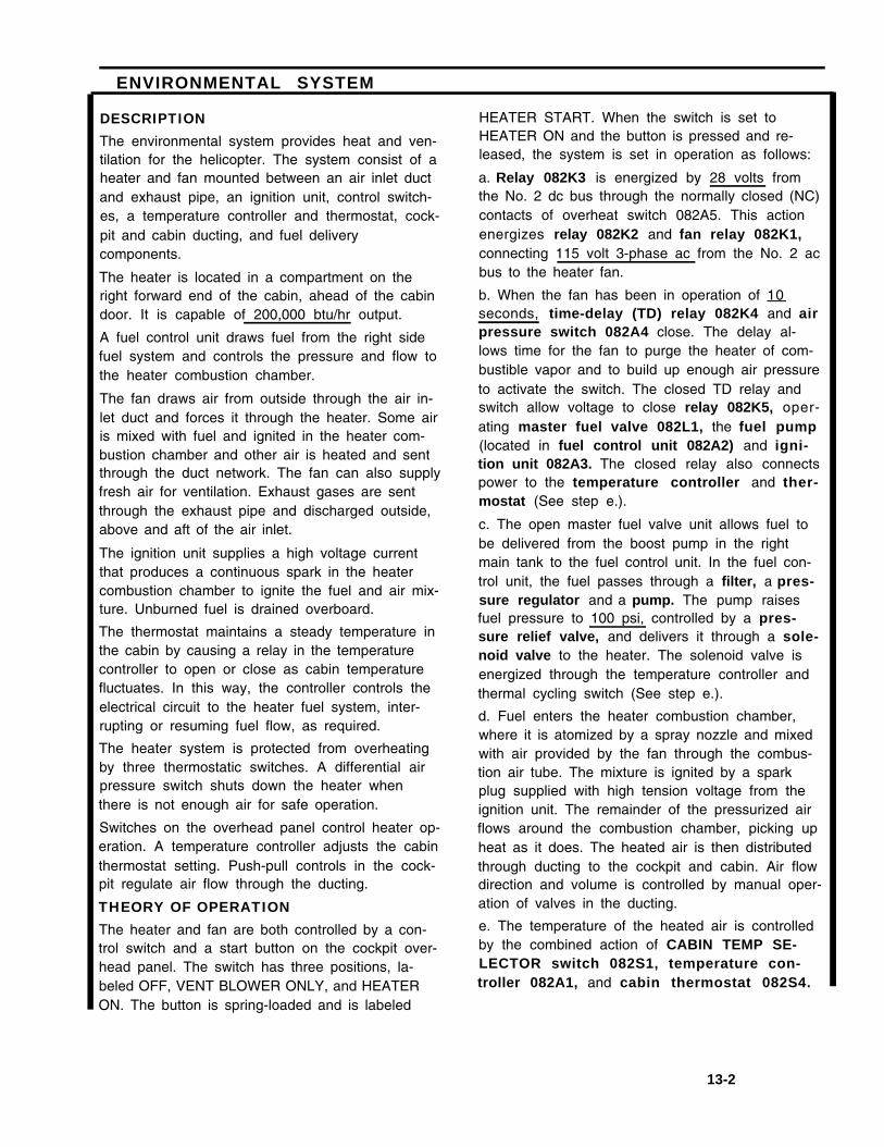
ENVIRONMENTAL SYSTEM
DESCRIPTION
The environmental system provides heat and ven-tilation for the helicopter. The system consist of aheater and fan mounted between an air inlet ductand exhaust pipe, an ignition unit, control switch-es, a temperature controller and thermostat, cock-pit and cabin ducting, and fuel deliverycomponents.
The heater is located in a compartment on theright forward end of the cabin, ahead of the cabindoor. It is capable of 200,000 btu/hr output.
A fuel control unit draws fuel from the right sidefuel system and controls the pressure and flow tothe heater combustion chamber.
The fan draws air from outside through the air in-let duct and forces it through the heater. Some airis mixed with fuel and ignited in the heater com-bustion chamber and other air is heated and sentthrough the duct network. The fan can also supplyfresh air for ventilation. Exhaust gases are sentthrough the exhaust pipe and discharged outside,above and aft of the air inlet.
The ignition unit supplies a high voltage currentthat produces a continuous spark in the heatercombustion chamber to ignite the fuel and air mix-ture. Unburned fuel is drained overboard.
The thermostat maintains a steady temperature inthe cabin by causing a relay in the temperaturecontroller to open or close as cabin temperaturefluctuates. In this way, the controller controls theelectrical circuit to the heater fuel system, inter-rupting or resuming fuel flow, as required.
The heater system is protected from overheatingby three thermostatic switches. A differential airpressure switch shuts down the heater whenthere is not enough air for safe operation.
Switches on the overhead panel control heater op-eration. A temperature controller adjusts the cabinthermostat setting. Push-pull controls in the cock-pit regulate air flow through the ducting.
THEORY OF OPERATION
The heater and fan are both controlled by a con-trol switch and a start button on the cockpit over-head panel. The switch has three positions, la-beled OFF, VENT BLOWER ONLY, and HEATERON. The button is spring-loaded and is labeled
HEATER START. When the switch is set toHEATER ON and the button is pressed and re-leased, the system is set in operation as follows:
a. Relay 082K3 is energized by 28 volts fromthe No. 2 dc bus through the normally closed (NC)contacts of overheat switch 082A5. This actionenergizes relay 082K2 and fan relay 082K1,connecting 115 volt 3-phase ac from the No. 2 acbus to the heater fan.
b. When the fan has been in operation of 10seconds, time-delay (TD) relay 082K4 and airpressure switch 082A4 close. The delay al-lows time for the fan to purge the heater of com-bustible vapor and to build up enough air pressureto activate the switch. The closed TD relay andswitch allow voltage to close relay 082K5, oper-ating master fuel valve 082L1, the fuel pump(located in fuel control unit 082A2) and igni-tion unit 082A3. The closed relay also connectspower to the temperature controller and ther-mostat (See step e.).
c. The open master fuel valve unit allows fuel tobe delivered from the boost pump in the rightmain tank to the fuel control unit. In the fuel con-trol unit, the fuel passes through a filter, a pres-sure regulator and a pump. The pump raisesfuel pressure to 100 psi, controlled by a pres-sure relief valve, and delivers it through a sole-noid valve to the heater. The solenoid valve isenergized through the temperature controller andthermal cycling switch (See step e.).
d. Fuel enters the heater combustion chamber,where it is atomized by a spray nozzle and mixedwith air provided by the fan through the combus-tion air tube. The mixture is ignited by a sparkplug supplied with high tension voltage from theignition unit. The remainder of the pressurized airflows around the combustion chamber, picking upheat as it does. The heated air is then distributedthrough ducting to the cockpit and cabin. Air flowdirection and volume is controlled by manual oper-ation of valves in the ducting.
e. The temperature of the heated air is controlledby the combined action of CABIN TEMP SE-LECTOR switch 082S1, temperature con-troller 082A1, and cabin thermostat 082S4.
13-2

ENVIRONMENTAL SYSTEM (Continued)
13-3

ENVIRONMENTAL SYSTEM (Continued)
13-4

ENVIRONMENTAL SYSTEM (Continued)
The switch is on the cockpit overhead panel. Thecontroller is in the heater compartment on the side ofthe HEATER CONTROL RELAY box at sta 95. The
thermostat is on the left side of the cabin at sta 335.
f. Power is provided through the switch to thecontroller and thermostat when relay 082K5 is ener-gized (See step b.). At the same time, power passesthrough the controller and thermal cycling switch082A7 to open the solenoid valve in fuel control082A2, permitting fuel to be delivered to the heater asdescribed in step c.
g. The cabin thermostat consists of a column ofmercury surrounded by a heater winding. Currentpasses through the variable retsistor within the temper-ature controller to heat the winding. When the windingraises the temperature of the mercury to 93oF (34oC),it opens contacts within the temperature controllerrelay. This removes power from the solenoid valvewithin the fuel control, shutting off fuel to the heater. Italso removes power from the heater winding, allowingthe mercury column to cool and contract. When thishappens, the relay contacts open, power is restored tothe fuel solenoid valve, and the heater starts.
08285 is a backup switch that functions if the cyclingswitch fails. lt opens to deenergize relay 082K3 when-ever air in the transition assembly below the heaterexceeds 350°F (1770C). . This shuts off the heater, butlets the fan continue to operate. At the same time, theHEATER HOT caution light on the master cautionpanel comes on. When this happens, the heatercannot be operated again until the transition assemblyhas cooled below 250°F (121oC. At that time, theheater can be started again by pressing the HEATERSTART button. A fan overrun switch 08286 keeps thefan operating after the heater has been shut down untilthe temperature within the heater drops below 120oF(49oC). lf the temperature rises to 120°F (49°C) again,the overrun switch will close and the fan will come onagain. This cycling will continue until the temperaturestays below 120°F (49oC).
i. Additional heater protection is provided by diffferen-tial air pressure switch 082A4, on the sta 95 bulk-head. This switch shuts down the fuel and ignitionsystems by deenergizing relay 082K5 if air pressurethrough the fan drops below 1.25 to 1.75 inches ofwater
h. Protection for the heater is provided by three j. When the switch on the cockgit overhead panel isthermal switches at the base of the heater. Cycling set to VENT FAN ONLY, only those contacts within theswitch 082A7 interrupts the circuit to the fuel control switch that energize the heater fan are dosed. Thesolenoid valve when temperature of the air leaving the blower then forces unheated ventilating air through theheater goes over 250°F (121o C), Overheat switch ducting.
13-5

ENVIRONMENTAL SYSTEM (Continued)
13-6

HEATING AND VENTILATING SYSTEM
1. Description
a. Provides heated and unheated air
The air conditioning is a heating and ventilation system which circulates either fresh or hot air tomaintain the cockpit and cabin areas at selected temperatures.
b. Fuel for the system
The main fuel solenoid valve is connected to a tapping in the right main engine fuel feel linelocated at Station 380 between the right main tank and aft auxiliary tank fuel pods. Thesolenoid valve controls the flow of fuel to the heater fuel control unit.
c. Blower
The blower consists of a fan, motor, and housing. It introduces air into the heater for heating orcooling purposes and, when ventilation is selected, introduces fresh air through the heater intothe system ducting. The blower is in the heater compartment between the heater adapterassembly and the air inlet duct.
d. Heater
(1) Location
The heater assembly is in the forward cabin right equipment compartment betweenStation 120 and Station 95. An acoustical blanket secured by hook and pile tape coversand shuts off the compartment from the rest of the forward cabin area.
(2) Purpose
The heater and heater fuel system provides and controls heated air for the aircraft. Thesystem consists of a blower fan which draws air into the heater fuel system which feedsand controls fuel to the heater, an ignition system for ignition of the fuel and air mixture inthe combustion chamber, a heater assembly, where the air may be heated, thermalcontrol and selector switches, and electrical wiring which provides a means of selectingand controlling the cabin air temperature and provide overheat protection.
e. Ducting
(1) Ducting is located in the cockpit and the cabin area.
(2) Purpose
To distribute fresh air or heated air to provide comfortable level of temperature to thecrew and passengers.
13-7

2. System Operation
a. Master function switch
(1) Location
Overhead panel in the cockpit.
(2) Purpose
To control the air conditioning system
(3) VENT Blower Only
(4) HEATER ON
(5) OFF
b. Heater Start button
(1) Location
Overhead panel in the cockpit
(2) Purpose
To provide a means of starting the heater
c. Temperature selection control
(1) Location
Overhead panel in the cockpit
(2) Purpose
The temperature selector is a rotary variable resistor which controls the current tothe temperature controller to maintain selected cabin air temperature.
d. Cabin thermostat
(1) Location
The cabin thermostat is on the left side of the cabin structure at Station 352.
(2) Purpose
The cabin thermostat is a mercury-filled temperature operated switching device.The mercury expands and contracts with change in cabin air temperature toprovide operating control of the relay in the temperature controller.
13-8

e. Cockpit air knob
(1) Location
There are two cockpit air controls. Each control is made from a sheathed push/pullsingle core cable, running from a control handle at the lower corner of the pilot andcopilot's instrument panels.
(2) Purpose
Each control is routed to the respective cockpit air outlet flap valve on each side ofthe cockpit floor console and just forward of the cockpit floor.
f. Air control handles
(1) Location
Cockpit Defrost and Cabin Heater Controls. These controls are mounted just rightof the center cockpit floor console. The marking on the panel is AIR CONTROLPULL FOR ON and for two controls are marked DEFOG or DEFROST and CABINAIR.
(2) Purpose
To give the cockpit-crew a means of regulating cockpit or cabin airflow.
g. Cargo compartment heat controls
(1) Location
Under the heater ducts on the left and right sides of the cargo compartment.
(2) Purpose
To give the cabin-crew a means of regulating the airflow into the cabin.
h. Heater caution light
(1) Master caution caption
HTG HOT caption comes on at 177°C (350°F)
(2) Overheat switch 177°C (350°F)
Should the temperature of air in the heater transition assembly rise to 350°F,overheat switch releases a relay. This shuts off the entire system except for theblower.
13-9

(3) Re-Start
The heating system cannot be operated again until the heater temperature hasreturned to normal and the HTG START button is pressed.
i. The 121°C (250°F) cycling switch
a. Location
In the transition assembly where the air leaves the heater.
b. Purpose
A cycling effect is provided by the 250°F cycling switch. This switch interrupts thecircuit to the fuel control solenoid valve when the temperature of air leaving theheater exceeds 250°F (121°C).
c. The 49°C (120°F) blower overrun switch.
(1) Purpose
After the heater is shutoff, blower overrun switch A6 keeps the blower inoperation until the temperature of the heater falls below 120°F (49°C).When the heater control switch is at VENT, the blower forces unheatedventilating air through the system ducting.
d. Heater ignition unit vibrator.
(1) Location
The ignition unit is on the cabin bulkhead at Station 95 on the lower rightside of the heater compartment.
(2) Purpose
The ignition unit consists of a relay, condenser, and noise filters in ahousing with a vibrator, ignition coil, and junction box mounted externally.The unit converts 28-volt dc to a high voltage oscillating current, whichproduces a continuous spark at the spark plug in the heater combustionchamber. The vibrator contains a spare set of contacts which can beselected, by operation of a switch on the unit junction box, to continueoperation of the ignition unit in event of failure of the vibrator main contacts.
13-10

CHAPTER 14HOISTS AND WINCHES
SECTION I
CARGO HANDLING SYSTEMDESCRIPTION
ANDTHEORY OF OPERATION
14-1

CARGO HANDLING SYSTEM
DESCRIPTION
The cargo handling system consists of a hydrauli-cally-operated winch and cable, a cable cutter,tackle blocks, and a remote-control grip and safe-ty harness. Stowage bags in the heater compart-ment are provided for the cable cutter and tackleblocks when not in use. System power and con-trol is provided through various hydraulic valvesand electrical switches and receptacles.
The heart of the cargo handling system is thewinch, mounted to the floor of the heater com-partment at the right forward corner of the cabin.It is powered by hydraulic pressure from the utilityhydraulic system. By changing cable routing, thewinch can be used to perform several differentfunctions:
Loading cargo into the cabin through theopen cargo door
Carrying or bringing on board cargo throughthe open rescue hatch while in the air
Personnel rescue operations
Parachute static line retrieval
Refer to TM 55-1520-240-10 for information onsetting up the system to perform these functions.
The winch has 150 feet of 1/4 inch steel cable. Ithas a 3,000 pound load capacity at a reel-inspeed of 20 feet per minute for cargo loadingthrough the cargo door. For hoisting operationsthrough the rescue hatch, it can lift 600 pounds ata reel-in speed of 100 feet per minute. For cargoloading, the effective winch capacity can be in-creased by reeving the cable through the cableblocks as described in TM 55-1520-240-10.
The winch system can be operated from either thecockpit or the cabin. Cockpit operation is by theHOIST panel on the overhead console. Cabin oper-ation is by a control grip that can be plugged intoan operator’s panel at sta 320 or receptacles atsta 95 or 502. If power is lost during operation, awinch-mounted brake will automatically lock thecable. During rescue operations, the cable isreeved through a cable cutter that is plugged intoa receptacle above the rescue hatch. During cargooperation, the cable cutter is stowed in the stow-age container and connected to a stowage recep-tacle in the heater compartment at sta 95.
14-2

CARGO HANDLING SYSTEM (Continued)
14-3

CARGO HANDLING SYSTEM (Continued)
THEORY OF OPERATION
The hoist system can be operated from the cock-pit or from any of three locations in the cabin.System operation is identical regardless of whichlocation is used. Operation described here is fromthe cockpit overhead panel, with the winch shift-ing lever at RESCUE. The control locations in thecabin can be used when the HOIST MASTERswitch on the cockpit overhead panel is atREMOTE.
1.
2.
3,
Placing the HOIST MASTER switch to Pl-LOT connects 28-volt dc from the bus to thespring-loaded center-off HOIST rotaryswitch. The rotary switch has a set of con-tacts that close whenever the switch is offcenter. When off center, these contacts en-ergize the winch brake control valve so-lenoid. When energized, this solenoiddirects pressurized hydraulic fluid to releasethe winch brake and to the P (pressure)port of the winch control valve.
Rotating the HOIST switch to OUT energizesthe winch control shutoff valve solenoid. Atthe same time, current flows from the rotaryswitch to energize the winch control valveOUT solenoid thru the out-limit switch on thewinch. Hydraulic fluid from the C 1 port ofthe winch control valve flows thru the pres-sure reducing valve. This reduces the pres-sure to 750 psi before it reaches the OUTport of the winch motor. This pressurizedfluid operates the hydraulic motor to reel outthe cable. The fluid returns to the systemthrough the IN port of the winch motor tothe winch control valve. A relief valve be-tween the hoist in line and system returnprotects the winch motor case shaft sealfrom high pressure.
When the HOIST switch is released to OFF,the winch control shutoff valve and thewinch control valve circuits open. The winch
control valve and shutoff valve return to thedeenergized position. This stops fluid flow tothe winch motor, to the brake release line,and the winch control valve. The winch con-trol shutoff valve then directs fluid from thebrake release line to the utility hydraulic sys-tem return line and the spring-loaded brakeis applied automatically.
4. Rotating the HOIST switch to IN closes thecontacts that complete the winch controlshutoff valve solenoid circuit. It also movesthe wiper of the rotary switch into contactwith the IN portion of the switch. Currentflows through the wiper arm to the IN sole-noid of the winch control valve, through theoverload limit and in-limit switches on thewinch, and the cable cutter plug. The IN so-lenoid positions the winch control valve todirect fluid through the C2 port of the valve,to the IN port of the winch motor. The pres-surized fluid operates the hydraulic motor toreel in the cable. The fluid returns to the sys-tem through the OUT port of the winch mo-tor, the pressure reducer, and the return portof the winch control valve.
5. When the CABLE CUTTER switch on eitherthe hoist control panel or the operator’s gripis ON, power from the 28-volt dc bus is con-nected to the cable cutter cartridge. In thiscondition, operation of the cable cutter fromeither the cockpit or cabin is independent ofthe HOIST MASTER switch.
6. Limit switches prevent winch overloading,stop winch OUT operation when the cable isextended 150 feet, and stop winch IN opera-tion when the cable is extended 28-1/2 feetin the rescue mode or extended 3 feet in thecargo mode. An overload limit switchopens the circuit when the load on the cableexceeds 3,100 to 3,200 pounds when thewinch is operated in the reel-in direction.
14-4

CARGO HANDLING SYSTEM (Continued)
7. A shifting lever on the winch controls atwo-speed gear train, labeled RESCUE (fast)and CARGO (slow). With the lever at RES-CUE, the cable cutter must be plugged intothe overhead CABLE CUTTER connector tocomplete the winch circuit. With the lever atCARGO, the cable cutter must be plugged in-to the stowage receptacle at sta 95 to com-plete the circuit. The shifting lever ismechanically linked to three transferswitches. These switches connect voltageto either the rescue or cargo in-limit switch.When the lever is at RESCUE, the rescue(fast) in-limit switch is connected in serieswith switch 1. With the lever at CARGO, thecargo (slow) in-limit switch is connected inseries with switch 2. Switch 3 is a safetydevice which interrupts the hoist-out circuitwhen switches 1 and 2 are open. This ar-rangement prevents the winch from operat-ing in either direction when the gears are notengaged.
8. In case of electrical failure, emergency hy-draulic operation of the winch is possible byoperating manual override knobs on thewinch control shutoff valve and thewinch control valve. The knob on theshutoff valve is an on-off valve that allowsfluid to flow through the system when it ispushed in. It can be locked in by rotating it.Winch reeling direction (cable in or out) iscontrolled by rotating the knob on the con-trol valve cw or CCW, When the manual over-ride knobs are used, the cable limit switchesare disabled, As a result, care is necessaryto prevent reeling the cable too far in or out.
14-5

CARGO HANDLING SYSTEM Continued)
14-6

CARGO HANDLING SYSTEM (Continued)
14-7

CHAPTER 15
AUXILIARY POWER UNIT
SECTION I
AUXILIARY POWER UNITDESCRIPTION
AND
SEQUENCE OF OPERATION
15-1

A. Auxiliary Power Unit Improvements
Description of Change, from that of the CH-47C configuration, is as follows:
1. Install the T-62T-2B (solar) auxiliary power unit in lieu of the T-62T-2A1 (solar) power unit.
2. The installation of this new auxiliary power unit is practically identical to that of the CH-47Caircraft.
3. The T-62T-2B APU includes the following features from that of the T-62T-2A1 APU:
a. T-62T-2A1 power section (current CH-47 unit).
b. Two pad gearbox (driving hydraulic motor/pump and 20 KVA alternator) similar to CH-46T-62T-11 APU gear box.
c. The speed switch and tach generator are removed and replaced with a magnetic pickupon the gearbox.
d. The oil pressure switch will be rewired to eliminate low oil pressure from shutting downthe APU. A new hermetically sealed switch replaces the existing switch.
e. The fuel pressure switch is removed.
f. The exhaust temperature switch is removed and replaced with an exhaust thermocouple.
g. An electronic, solid state, speed sequencing and control unit (ESU) to regulate startingand protective functions is added.
h. The apu hour-meter is removed.
i. External plumbing and wiring harnesses were modified as necessary to support theforegoing changes.
B. Description
1. Function
The gas turbine auxiliary power unit T62-T-2B (APU) is mounted in the aft cabin above theramp. The basic components of the apu are the gas turbine engine hydraulic motor-pump, fuelcontrol, accessory drive, and ac generator. An apu electronic sequence unit, which monitorsapu operation is on the left side of the cabin above the ramp. The motor-pump on the apupressurizes the utility and flight control hydraulic systems for main engine starting and groundchecks. The apu also drives an ac generator which supplies power to No. 1 and No. 2electrical systems.
15-2

The apu oil supply is integral and contained within the sump of the accessory drive assembly.The apu receives fuel from the left fuel system through a boost pump, a manual shutoff valve,and a solenoid valve.
2. Control Components
a. Electronic Sequence Unit (ESU)
The ESU is mounted on the left side of the cabin above the ramp. The unit monitors apustarting and operation. It monitors apu speed and exhaust gas temperature. Itcontinuously compares these parameters with limits programmed into control box circuits.If a limit is exceeded, the control box will automatically shutdown the apu. Four magneticbuilt-in test equipment (bite) indicators are on the control box. These indicators are eitherblack or white. A label on the control box explains the various bite indications and theirmeaning.
b. APU Control Switch
The apu control switch is on the electrical power panel on the overhead switch panel. Itis a three-position switch marked APU OFF, START, and RUN. The switch is spring-loaded from START to RUN. To start the apu, the switch is moved from OFF to RUN for3 to 5 seconds, then set to START for 2 seconds, then released to RUN. APU start isthen automatic and controlled by the control box. The APU ON caution light will come onin about 10 to 12 seconds. To stop the apu, the switch is set to OFF. Normally, electricalpower to control apu operation is from the 28-volt essential DC bus through the APUCONT NORM circuit breaker on No. 1 power distribution panel. Emergency power tocontrol the apu is from the battery bus through the APU CONT EMERG circuit breaker onthe No. 1 power distribution panel.
c. APU ON Caution Light
The APU ON caution light is on the master caution panel. Normally, the APU is intendedfor ground operation only. It is not intended for operation during flight. If the lightremains illuminated following take-off, it alerts the pilot to shutdown the apu. When thelight is on, it indicates the apu is up to speed, exhaust gas temperature, oil pressure, andoil temperature are normal. It does not necessarily indicate that apu hydraulic pump orgenerator output is normal. If the rotors are not turning, check the UTIL HYD SYS andRECT OFF caution lights to evaluate output of the apu hydraulic pump and generator.The APU ON caution light is controlled by the apu control box.
C. Limitations and Precautions
1. Automatic Shutdown
a. ESU Processor Board Failure
b. ESU Sensor/Data Board Failure
15-3

c. Over-temperature
d. Over-speed
e. Under-speed
f. Fail to Start
g. Loss of Speed Data
h. Shorted Thermocouple Probe
i. Open Thermocouple
j. Processor Sequence Fail
k. No Temperature Data
2. Max rear wind-speed for APU Start - 25 Kts
TEACHING PROCEDURE
D. Description
1. General
a. Helicopter contains APU system to provide hydraulic and electrical power for engine startand ground maintenance.
b. System contains an APU, an electronic sequence unit, a Start module, and a fuel system.
c. APU contains a motor-pump and an AC generator
d. Electronic sequence unit is a microprocessor with built-in test equipment.
e. ESU controls Start of APU and then monitors operation
f. System operates on 28 volts DC from essential bus for normal start and from the battery bus for emergency Start.
g. Fuel system contains pump, fuel solenoid valve and manual shutoff valve. (in-line filter,main filter, governor)
h. Hydraulic system contains accumulator, start module and motor-pump
E. Presentation
1. Components
a. Auxiliary power unit (P/N T-62T-2B)
15-4

(1) Location
(a) Mounted in the extreme aft end of helicopter Station 600, waterline +60
(b) Accessible from the ramp area
(2) Function
(a) Provide electrical power for ground maintenance
(b) Provide hydraulic power for engine start and ground maintenance
(3) Construction
(a) Gas turbine engine with the following:
1 Electrical harness
2 Fuel control and associated equipment
3 Mounting pads for generator and hydraulic motor-pump
(4) Operation
(a) Electrical power to ESU starts operation sequence
(b) Hydraulic sequence valve opens and pressure directed to motor-pump
(c) Fuel and ignition are programmed to APU
(d) At certain speeds, controlled by ESU, events occur until APU is to operatingspeed
(e) Motor then becomes a pump and APU ON light on caution panel comes on
(f) Generator is ready for use and hydraulic pressure available.
(5) Specifications
(a) Rated Speed - 58,355 rpm (100% rated speed)
(b) Max Allowable - 6,794 rpm
(c) Weight - 74.8 (including residual fluids)
(d) Std Operating Conditions - Sea level to 15,000 ft. altitude
(e) Rated Output Power - 95 SHP max
(f) Rated Output Power - 66 SHP normal
15-5

(g) Max Rated Exhaust Gas Temp - 1130°F
(h) Fuel Consumption - 115 PPH at 95 SHP- 89 PPH at 66 SHP
(i) Model No. - T-62T-2B
(6) Reduction Drive Assembly
(a) Location
1 On the fwd portion of the Power Plant Assembly and bolted to theTurbine Assembly
(b) Function
1 Reduces the output rotational speed (58,255 rpm) of the RotorAssembly (Turbine Assembly) to speeds necessary to drive the engineaccessories and engine-driven equipment.
(c) Specification
1 Input Speed (rated) - 38,225 rpm
2 Output Speed (at rated input)
a Axial Pad - 8216 rpm
b Right Angle Pad - 8000 rpm
c Accessory Pad - 4242 rpm
3 Magnesium Housing
(d) Construction
1 Axial Pad - Mounting position of APU motor pump
2 Accessory Pad - Mounting of fuel pump and Acceleration ControlAssembly
3 Right Angle Pad - Mounting of 20 KVA generator
b. Electronic sequence unit (ESU) (P/N 160200-200)
(1) Location
(a) Located at Station 585, WL 50 left side
(b) Accessible from the ramp area
15-6

(2) Function
(a) Controls the Start sequence of the APU
(b) Monitors APU for faults and shuts down APU if fault occurs
(3) Construction
(a) Contains microprocessor and program in read only memory (ROM)
(b) Has built in fault display
1 Four magnetically latched indicators
(c) Two electrical connectors for interface to aircraft wiring
(d) Microprocessor runs check on itself every 40 milliseconds during Startsequence
(e) Checks APU operating parameters at least once every 40 millisecondsduring operation
(4) Operation
(a) Operates on 28 volts DC
(b) When switch on overhead panel is set to run, voltage is supplied to
1 Airframe fuel pump
2 Fuel solenoid valve
3 ESU
(c) ESU bite indicators are reset
(d) Placing switch to start opens hydraulic valve
(e) Start sequence is started and continues as programmed
(f) ESU compares APU speed and initiates the next sequence
(g) After start is complete, ESU monitors APU and itself
c. Fuel System
(1) Location
(a) Fuel pump and solenoid valve in aft left inter-tank area
(b) Manual shutoff valve located at Station 540, left side
15-7

(2) Function
(a) Supply fuel to APU
(b) Provide means to shutoff fuel to APU in emergencies
(3) Operation
(a) Pump and solenoid valve operate on 28 volts DC
(b) When APU start switch placed to run, 28 volts directed to pump and valvethrough fault relay
(c) When ESU detects a fault, fault relay is energized and interrupts voltage topump and valve
(d) Manual valve can be operated to shutoff fuel flow to APU. Access fromoutside or inside
d. APU start module
(1) Location
(a) Right side of ramp area, Station 585, WL 60
(b) On outboard side of aft transmission enclosure
(2) Function
(a) Controls application of hydraulic pressure to APU motor-pump and spinsAPU until it starts
(3) Operation
(a) Operates on 28 volts DC
(b) When start switch placed to Start, ESU signals pilot solenoid valve to open
(b) This operates pressure operated valve and directs pressure to APU motor-pump
(d) When APU reaches 90% of speed, start solenoid is closed
(e) Motor-pump becomes pump and supplies pressure to utility system
2. System Operation
a. Electrical power to operate the APU system is obtained from -
28 VDC - essential bus - normal operational through APU cont nor CB
28 VDC - battery bus - emergency operation through APU cont emer CB
15-8

b. APU accumulator must have a 3000 psi charge
c. Placing APU Start switch to run closes contacts 4-5. The 28 volts DC from terminal 4 ofthe APU switch is applied to three circuits. This voltage is applied to the ESU for powerand to reset the bite indicators. Also applied through fault relay contacts to open the fuelsolenoid valve and run the fuel pump.
d. When terminals 1-2 are closed with switch in start, voltage from terminal 1 goes to ESUand provides a start signal. This operates the hydraulic valve. Pressurized fluid from theaccumulator flows through the valve and motors the motor-pump and the APU.
e. As the APU starts to rotate, a magnetic pickup generates a signal proportional to APUspeed. The APU processes this speed signal which schedules events at 5, 14, 70, and90% of rated speed. The ESU also monitors exhaust gas temperature. A thermocouplein the combustor assembly generates a signal which is proportional to EGT. When theAPU reaches 5% of rated speed a 40 second timer starts. If the APU does not completea Start in 40 seconds, the fault relay operates and stops fuel flow to the APU.
f. At 5% rated speed, the ESU applies a start fuel signal (28 volts) to the APU. This signalopens the start-fuel valve and power the exciter. The exciter provides a high-energypulse to the spark plug. Fuel is directed through the start fuel nozzle and vaporized in thecombustor where it is ignited by the spark plug. This action increases APU speed.
g. At 14% rated speed, the ESU applies the main fuel signal to the APU. This signal opensthe main fuel valve. From this valve, fuel flows through the fuel manifold assembly andsix vaporizer tubes to the combustor. This additional fuel accelerates the APU.
h. At about 20% of rated speed, the APU start accumulator depletes its charge. Thiscauses the motor-pump to shift to neutral.
i. At 70% rated speed, the start-fuel signal stops. The exciter and Start fuel are turned off.Combustion is self-sustaining.
j. At 90% rated speed, ESU closes the start valve, and generates a 90% rpm switch onsignal. The motor-pump shifts to a pump and recharges the accumulator. The 90% rpmswitch on signal starts a 1.5 second timer. After 1.5 seconds, the ESU applies 28 volts tothe APU ON capsule on the master caution panel.
k. The ESU then monitors the APU for faults and shuts the APU down when a fault occurs.
l. Over temp during start is a temperature 1250°F, over temp during operation is atemperature 1150°F, over speed is a speed 110% of rated speed. Under speed is aspeed (90% after 90% plus 1.5 seconds).
15-9

CHAPTER 16
MISSION EQUIPMENT
SECTION I
CARGO CARRYING HOOK SYSTEM
DESCRIPTION
A N D
THEORY OF OPERATION
16-1

EXTERNAL CARGO HOOK SYSTEM
DESCRIPTION
The external cargo hook system consists of threeseparate cargo hooks mounted on the undersideof the helicopter. The system allows a single loadto be carried suspended at up to three points or
three separate loads to be carried at the same
time.
The center cargo hook is suspended from a beamunder the cabin floor at station 331. The hook is
attached to the beam with a bolt that lets thehook swing to each side. The beam is carried inbearings attached to structure at the sides of therescue hatch in the floor. It can pivot forward and
aft from the attaching points,
When not in use, the hook is stowed between
cabin floor and rescue hatch door. In use, thehatch door is opened and the hook is unstrapped
to hang down through the open hatch. The hook
hook to swing forward and aft and from side toside. Normally the hook is electrically actuatedthrough a connector on the fuselage skin. It can
also be released manually through a cable thatconnects to a release mechanism. The lifting ca-
pacity of each hook is 17,000 pounds. When
used together, the two hooks can lift a load of
25,000 pounds.
All three hooks can be released in any one ofthree modes — normal, emergency, or manual.See Task 16-2 for a description of hook operationin each of these modes.
Power to operate the cargo hook system in nor-
mal operation comes from the No. 228 volt dcbus. Two circuits are provided, each controlled by
a separate circuit breaker. One circuit provides
power to the system. The other contains the con-trol switches and relays. Two separate power and
lifting capacity is 26,000 pounds. control circuits are provided for emergency release
The forward and aft hooks hang from fittings at-of the hooks. Again, each has its own circuitbreaker.
tached to the floor beams at stations 249 and
409. Each fitting is a universal type that allows the
16-2

EXTERNAL CARGO HOOK SYSTEM (Continued)
16-3

EXTERNAL CARGO HOOK SYSTEM (Continued)
CENTER CARGO HOOK LOADING POLEThe cargo hook loading pole is used to pick upthe sling loop of external cargo loads from insidethe helicopter. The loop is then placed on the car-go hook by hand. The pole has a hook at one endand a cable at the other end. The cable is at-tached to the fuselage to prevent accidental lossof the pole when in use and to provide a dis-charge path for static electricity.When not in use the pole is stowed on the lowerright side of the cabin at about sta 360, just be-low the heater duct.
Make sure the ground cable isconnected when using the load-ing pole. With the rotors turning,static potential between the he-licopter and a load on theground can be as high as 40,000volts.
THEORY OF OPERATIONNormal Release
NOTE
The relays referred to in this sectionare in the Normal Release Relay Boxat the right side of the cabin near sta280.
Setting the MASTER switch on the CARGOHOOK control panel to ARM energizes powercontrol relay K1 through the control circuitbreaker, The energized relay lights the ARMEDSW FAIL light on the cabin relay box and arms thefollowing:
System power circuit, through the power cir-cuit breaker
CARGO REL buttons on the pilot’s and co-pilot’s control stick grips
CARGO HOOK switch on the HOIST OP-ERATOR PANEL in the cabin
Ground relay K4 contacts
Center hook release relay K3 contactsForward hook release relay K8 contactsAft hook release relay K9 contacts
Setting the CARGO HOOK switch on the HOISTOPERATOR PANEL to ARM arms the CARGOHOOK RELEASE switch on the control grip in thecabin.Operating the hook release button on either of thecontrol stick grips or the hook release switch inthe cabin energizes ground relay K4, which isthen latched energized through its own contacts.The RELEASE SW FAIL and GROUND RELAY AC-TIVATE lights on the relay box come on. TheFAIL light stays lit as long as the release switch(or button) is held. The ACTIVATE light will staylit as long as relay K4 stays energized.The closed contacts of relay K4 also provide aground for the center hook hydraulic solenoidvalve and for the normal release relay circuits ofthe forward and aft hook.Finally, the release switch (or button) energizesone or more of release relays K3 (center), K 8(forward), and K9 (aft), depending on the positionof the HOOK SELECT switch on the cockpit over-head panel. Current from the power circuit flowsthrough the closed release relay contacts to ener-gize the release solenoid of the selected hook.
16-4

EXTERNAL CARGO HOOK SYSTEM (Continued]
16-5

EXTERNAL CARGO HOOK SYSTEM (Continued)
If the center cargo hook has been selected, thefollowing sequence takes place:
With hydraulic solenoid valve 134L1 en-ergized to open, pressurized fluid from theutility hydraulic system flows to the hook ac-tuating cylinder. The cylinder is forced up-ward and the hook opens.
As the hook opens, it closes normally-openswitch S3. At the same time, the movingcylinder closes normally-open switch S2.These switches complete the circuit to lightthe MID HOOK OPEN light on the master cau-tion panel.
The hook will remain open until theMASTER switch on the cockpit overheadpanel or the CARGO HOOK switch on thecabin panel is momentarily set to RESET.When this is done, latched relays K3 and K4are deenergized, closing the hydraulic sole-noid valve. The flow of hydraulic fluid to thecylinder is stopped and the fluid return line isopened, allowing pneumatic pressure storedin the cylinder to close the hook.
If the forward or aft cargo hook has been se-Iected, the following sequence takes place:
When the release solenoid is energized, itmoves the hook’s release arm up, un-latching the release lever that holds the loadbeam closed. Assuming that the load isheavy enough to overcome the spring-loadingof the beam, the beam pivots open, releasingthe load. With the load released, the spring-Ioading closes the hook.
Almost immediately after the release solenoidis energized, a solenoid protection switchon the hook opens to reenergize the normalrelease relay. This deenergizes the sole-noid, causing the protection switch to openagain. The release solenoid is re-energizedand the entire sequence repeats, continuinguntil the hook release button or switch isreleased.
When a hook is open, hook-open andlinkage-open limit switches on the hookclose. This energizes relay K5 (aft) or K6 (for-ward) to close. Contacts on these relays
close to light the FWD or AFT HOOK OPENlights on the master caution panel. When thecockpit MASTER switch or the cabinCARGO HOOK switch is set to RESET,the relays are deenergized and the lights goout.
A hook-loaded switch on each hook closeswhen a load of about 150 pounds is applied.The closed switch completes a circuit to lightthe forward or aft HOOK LOADED light in thecockpit.
Emergency Release
NOTE
The relays referred to in this sectionare in the Emergency Hook ReleaseRelay Box at left side of the cabinnear sta 280.
In the emergency release mode, all three hooksare opened at the same time by operating theEMER REL ALL guarded switch on the cock-pit overhead panel. The sequence of operation isas follows:
When the emergency switch is operated, cur-rent from the flight essential bus flowsthrough the CARGO HOOK CONT EMER RLSEcircuit breaker and the switch to engage re-lay K1 and time delay relay K2.
Closed contacts in energized relay K 1 allowcurrent to flow through the CARGO HOOKCONT EMER RLSE circuit breaker to closecontacts in the time delay relay. This acti-vates the relay, holding the contacts closedfor 10 seconds after the cockpit switch is re-leased. These closed contacts hold the con-tacts in relay K1 closed for the same 10-sec-ond period. The closed K 1 contacts keep arelease solenoid on each of the three hooksenergized.
The energized release solenoid on the centerhook allows pneumatic pressure from achamber in the hook actuating cylinder toflow to an auxiliary piston in the cylinder. Mo-tion of this piston raises the cylinder to openthe hook. When the solenoid is deenergized(after 10 seconds), the directed pressure is
16-6

EXTERNAL CARGO HOOK SYSTEM {Continued]
vented to atmosphere. The remaining pres-sure in the pressurized chamber moves thecylinder to close the hook.
The release solenoids at the forward and afthooks unlatch the hooks, allowing the load topull them open. With the load released, thespring-loaded hooks close, latching when therelease solenoids are deenergized (10seconds after being deenergized).
Manual Release Without
Manual release of the center cargo hook is doneby pulling a D-shaped ring at the top front of thehook. Pulling the D-ring releases a cam lock mech-anism, allowing the hook to pivot open. SwitchS2 closes to light the MID HOOK OPEN capsuleon the master caution panel. The hook is resetmanually by pushing up on the tip to lock thecams into position. When the hook is reset,switch S2 opens and the HOOK OPEN light goesout.
Manual release of the forward and aft hooks isdone by the handle in the rescue hatch. Pulling thehandle aft rotates a lever arm in each hook. Thisfrees a latch to pivot away from the load beam(hook). The weight of the load is then free to pullthe load beam open and the load drops. At the
16-7
same time, an actuator in the hook linkage lightsthe FWD and AFT HOOK OPEN lights on themaster caution panel. The hooks then return tothe closed and latched position and the lights goo u t
Manual Release With
Manual release of the center, forward, and aft car-go hooks is accomplished by using the handle inthe rescue hatch.
Pulling the handle aft releases a cam lock mecha-nism, allowing the center hook to pivot open.Switch S2 closes to light the MID HOOK OPENcapsule on the master caution panel. The hook isreset manually by pushing up on the tip to lockthe cams into position. When the hook is reset,switch S2 opens and the HOOK OPEN light goesout.
Pulling the handle aft also rotates a lever in theforward and aft hooks, This frees a latch to pivotaway from the load beam (hook). The weight ofthe load is then free to pull the load beam openand the load drops. At the same time, an actuatorin the hook linkage lights the FWD and AFT HOOKOPEN lights on the master caution panel. Thehooks then return to the closed and latched posi-tion and the lights go out.
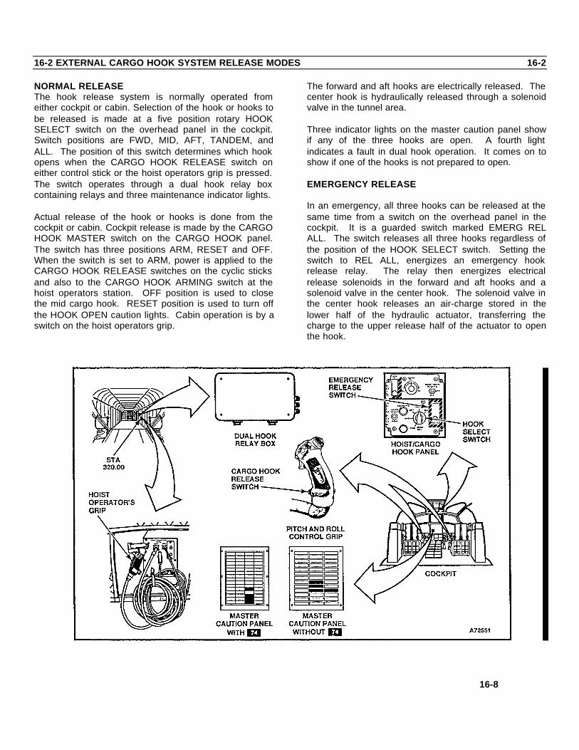
16-2 EXTERNAL CARGO HOOK SYSTEM RELEASE MODES 16-2
NORMAL RELEASEThe hook release system is normally operated fromeither cockpit or cabin. Selection of the hook or hooks tobe released is made at a five position rotary HOOKSELECT switch on the overhead panel in the cockpit.Switch positions are FWD, MID, AFT, TANDEM, andALL. The position of this switch determines which hookopens when the CARGO HOOK RELEASE switch oneither control stick or the hoist operators grip is pressed.The switch operates through a dual hook relay boxcontaining relays and three maintenance indicator lights.
Actual release of the hook or hooks is done from thecockpit or cabin. Cockpit release is made by the CARGOHOOK MASTER switch on the CARGO HOOK panel.The switch has three positions ARM, RESET and OFF.When the switch is set to ARM, power is applied to theCARGO HOOK RELEASE switches on the cyclic sticksand also to the CARGO HOOK ARMING switch at thehoist operators station. OFF position is used to closethe mid cargo hook. RESET position is used to turn offthe HOOK OPEN caution lights. Cabin operation is by aswitch on the hoist operators grip.
The forward and aft hooks are electrically released. Thecenter hook is hydraulically released through a solenoidvalve in the tunnel area.
Three indicator lights on the master caution panel showif any of the three hooks are open. A fourth lightindicates a fault in dual hook operation. It comes on toshow if one of the hooks is not prepared to open.
EMERGENCY RELEASE
In an emergency, all three hooks can be released at thesame time from a switch on the overhead panel in thecockpit. It is a guarded switch marked EMERG RELALL. The switch releases all three hooks regardless ofthe position of the HOOK SELECT switch. Setting theswitch to REL ALL, energizes an emergency hookrelease relay. The relay then energizes electricalrelease solenoids in the forward and aft hooks and asolenoid valve in the center hook. The solenoid valve inthe center hook releases an air-charge stored in thelower half of the hydraulic actuator, transferring thecharge to the upper release half of the actuator to openthe hook.
16-8

16-2 EXTERNAL CARGO HOOK SYSTEM RELEASE MODES 16-2(Continued)
After emergency release, the forward and aft hook willrelatch, automatically. The center hook must bemanually reset and recharged with air to 2,000 to 2,200psi.MANUAL RELEASE WITHOUT 35
If needed, all three hooks can be released by manualcontrols in the cabin rescue hatch area. The centerhook has a manual release handle (D-ring). Pulling thering unlocks the hook and lets it drop open. The forwardand aft hooks are released at
the same time by pulling a lever at the right side of thehatch. The center hook must be closed by hand aftermanual release. The forward and aft hooksautomatically reset closed after release. Manual releaseof all hooks is independent of the electrical, hydraulic,and pneumatic release systems.
MANUAL RELEASE WITH 35
All three hooks can be released at the same time bypulling a lever located at the right side of the hatch.
16-9