Embed Size (px)
Citation preview
Ch. 4 – Wireless Topologies
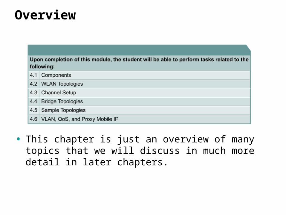
Overview
• This chapter is just an overview of many topics that we will discuss in much more detail in later chapters.

Components
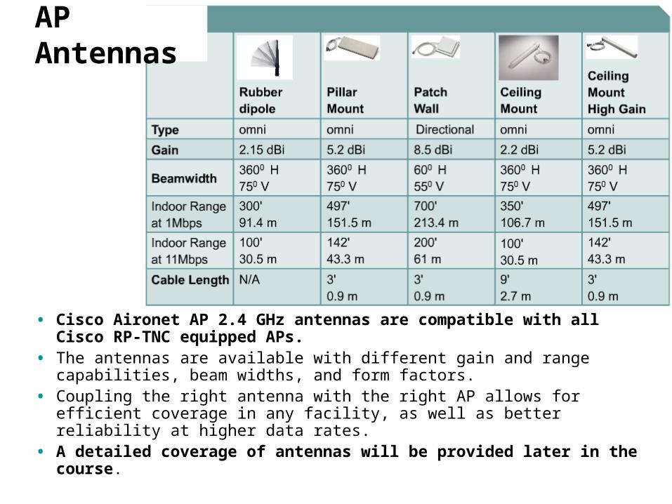
• Cisco Aironet AP 2.4 GHz antennas are compatible with all Cisco RP-TNC equipped APs.
• The antennas are available with different gain and range capabilities, beam widths, and form factors.
• Coupling the right antenna with the right AP allows for efficient coverage in any facility, as well as better reliability at higher data rates.
• A detailed coverage of antennas will be provided later in the course.
AP Antennas

• Cisco Aironet bridge 2.4 GHz antennas provide transmission between two or more buildings.
• Antennas operate at Layer 1 of the OSI Model.• Remember that the physical layer defines the electrical, mechanical, procedural,
and functional specifications for activating, maintaining, and deactivating the physical link between end systems.
• Characteristics such as voltage levels, timing of voltage changes, physical data rates, maximum transmission distances, physical connectors, and other, similar, attributes are defined by physical layer specifications.
Bridge Antennas
WLAN Topologies
Many of these features depend upon the vendor and whether the AP is a consumer wireless product or
business/enterprise wireless product.
Not all of these features are available on all APs or by all vendors.
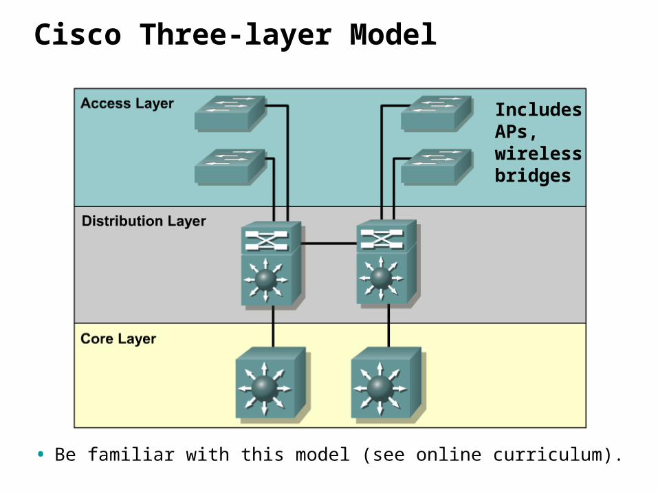
Cisco Three-layer Model
• Be familiar with this model (see online curriculum).
Includes APs, wireless bridges
Local area networks (LAN)
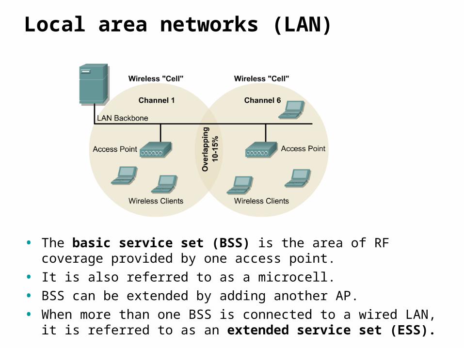
• The basic service set (BSS) is the area of RF coverage provided by one access point.
• It is also referred to as a microcell.
• BSS can be extended by adding another AP.
• When more than one BSS is connected to a wired LAN, it is referred to as an extended service set (ESS).
Local area networks (LAN)
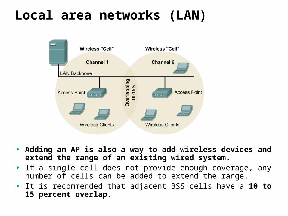
• Adding an AP is also a way to add wireless devices and extend the range of an existing wired system.
• If a single cell does not provide enough coverage, any number of cells can be added to extend the range.
• It is recommended that adjacent BSS cells have a 10 to 15 percent overlap.
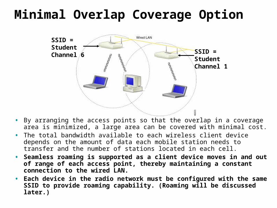
Minimal Overlap Coverage Option
• By arranging the access points so that the overlap in a coverage area is minimized, a large area can be covered with minimal cost.
• The total bandwidth available to each wireless client device depends on the amount of data each mobile station needs to transfer and the number of stations located in each cell.
• Seamless roaming is supported as a client device moves in and out of range of each access point, thereby maintaining a constant connection to the wired LAN.
• Each device in the radio network must be configured with the same SSID to provide roaming capability. (Roaming will be discussed later.)
SSID = Student Channel 6
SSID = Student Channel 1
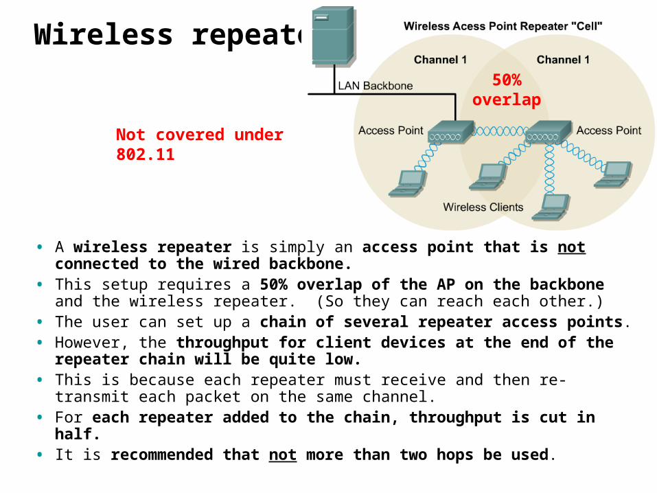
Wireless repeater
• A wireless repeater is simply an access point that is not connected to the wired backbone.
• This setup requires a 50% overlap of the AP on the backbone and the wireless repeater. (So they can reach each other.)
• The user can set up a chain of several repeater access points. • However, the throughput for client devices at the end of the repeater
chain will be quite low. • This is because each repeater must receive and then re-transmit each
packet on the same channel.• For each repeater added to the chain, throughput is cut in half. • It is recommended that not more than two hops be used.
Not covered under 802.11
50% overlap
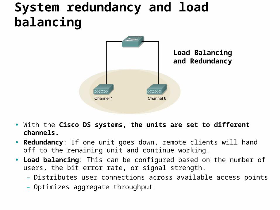
System redundancy and load balancing
• With the Cisco DS systems, the units are set to different channels.
• Redundancy: If one unit goes down, remote clients will hand off to the remaining unit and continue working.
• Load balancing: This can be configured based on the number of users, the bit error rate, or signal strength. – Distributes user connections across available access points – Optimizes aggregate throughput
Load Balancing and Redundancy
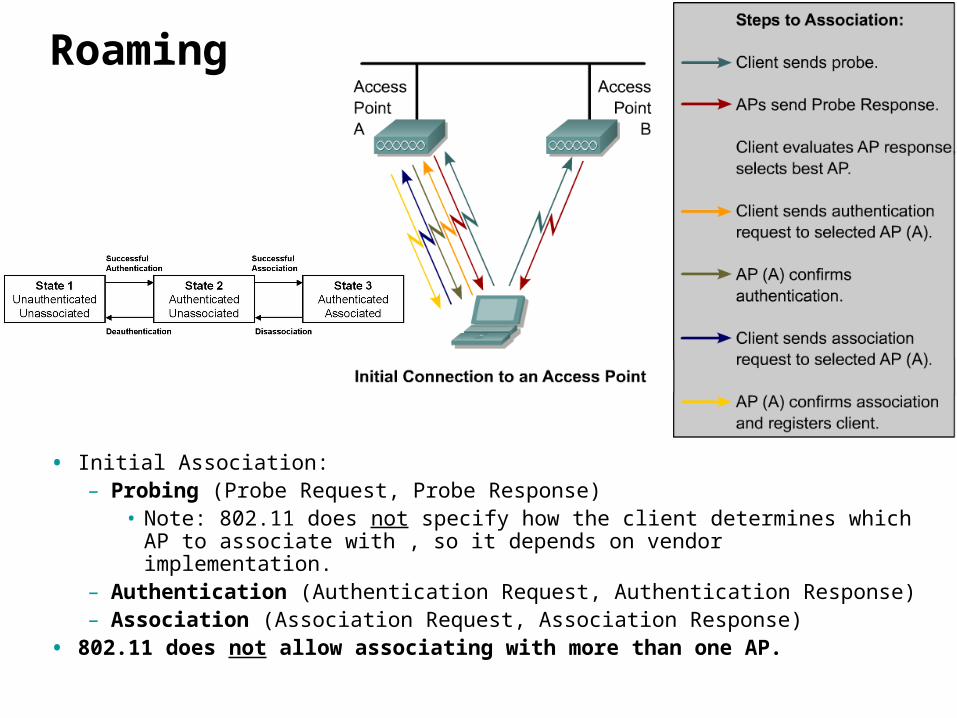
Roaming
• Initial Association:– Probing (Probe Request, Probe Response)
• Note: 802.11 does not specify how the client determines which AP to associate with , so it depends on vendor implementation.
– Authentication (Authentication Request, Authentication Response)– Association (Association Request, Association Response)
• 802.11 does not allow associating with more than one AP.
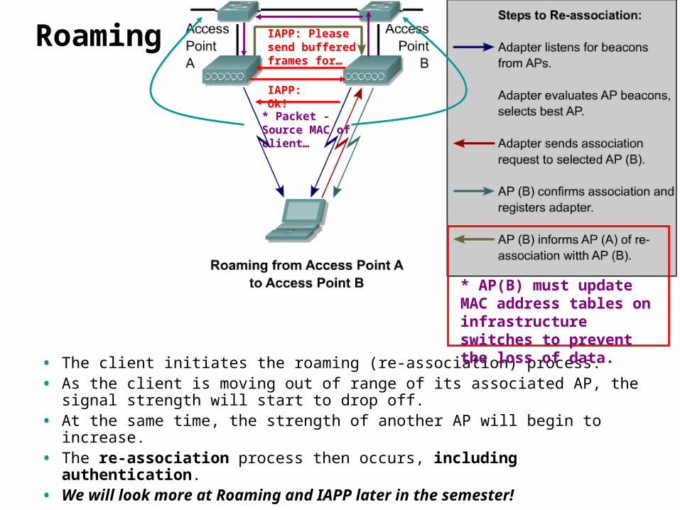
Roaming
• The client initiates the roaming (re-association) process.• As the client is moving out of range of its associated AP, the signal
strength will start to drop off. • At the same time, the strength of another AP will begin to increase. • The re-association process then occurs, including authentication.• We will look more at Roaming and IAPP later in the semester!
IAPP: Please send buffered frames for…
IAPP: Ok!
* AP(B) must update MAC address tables on infrastructure switches to prevent the loss of data.
* Packet - Source MAC of client…
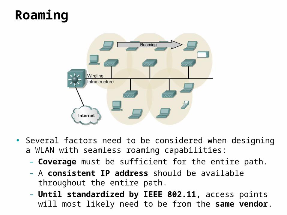
Roaming
• Several factors need to be considered when designing a WLAN with seamless roaming capabilities: – Coverage must be sufficient for the entire path. – A consistent IP address should be available throughout the entire
path. – Until standardized by IEEE 802.11, access points will most likely
need to be from the same vendor.
Roaming
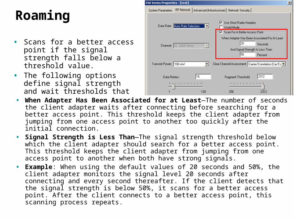
• Scans for a better access point if the signal strength falls below a threshold value.
• The following options define signal strength and wait thresholds that trigger a new scan.
• When Adapter Has Been Associated for at Least—The number of seconds the client adapter waits after connecting before searching for a better access point. This threshold keeps the client adapter from jumping from one access point to another too quickly after the initial connection.
• Signal Strength is Less Than—The signal strength threshold below which the client adapter should search for a better access point. This threshold keeps the client adapter from jumping from one access point to another when both have strong signals.
• Example: When using the default values of 20 seconds and 50%, the client adapter monitors the signal level 20 seconds after connecting and every second thereafter. If the client detects that the signal strength is below 50%, it scans for a better access point. After the client connects to a better access point, this scanning process repeats.
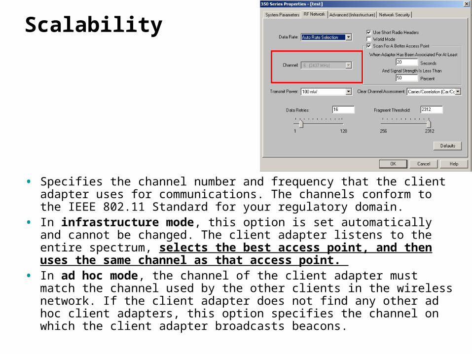
Scalability
• Specifies the channel number and frequency that the client adapter uses for communications. The channels conform to the IEEE 802.11 Standard for your regulatory domain.
• In infrastructure mode, this option is set automatically and cannot be changed. The client adapter listens to the entire spectrum, selects the best access point, and then uses the same channel as that access point.
• In ad hoc mode, the channel of the client adapter must match the channel used by the other clients in the wireless network. If the client adapter does not find any other ad hoc client adapters, this option specifies the channel on which the client adapter broadcasts beacons.
Channel Setup
Multiple Overlapping Networks Coverage Option
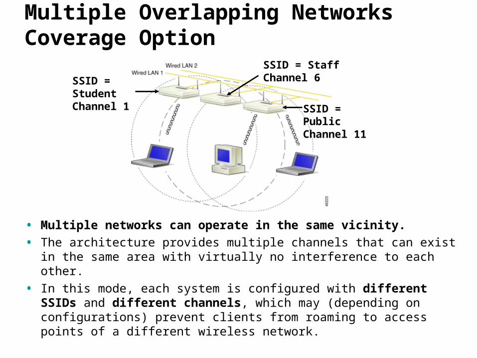
• Multiple networks can operate in the same vicinity.
• The architecture provides multiple channels that can exist in the same area with virtually no interference to each other.
• In this mode, each system is configured with different SSIDs and different channels, which may (depending on configurations) prevent clients from roaming to access points of a different wireless network.
SSID = Student Channel 1
SSID = Staff Channel 6
SSID = Public Channel 11
Channel Setup
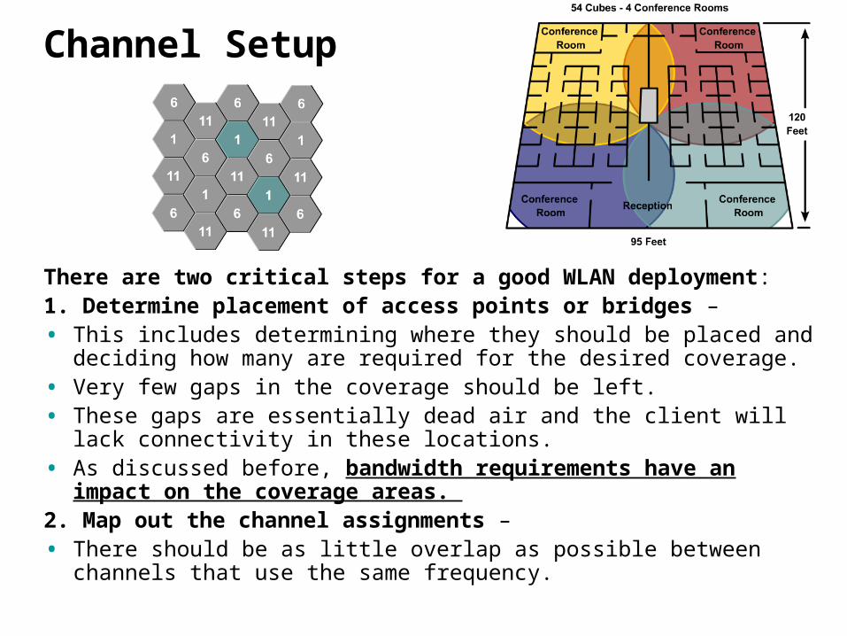
There are two critical steps for a good WLAN deployment: 1. Determine placement of access points or bridges – • This includes determining where they should be placed and deciding
how many are required for the desired coverage. • Very few gaps in the coverage should be left. • These gaps are essentially dead air and the client will lack connectivity
in these locations. • As discussed before, bandwidth requirements have an impact on
the coverage areas. 2. Map out the channel assignments – • There should be as little overlap as possible between channels that
use the same frequency.
Multiple Overlapping Networks Coverage Current Thinking:
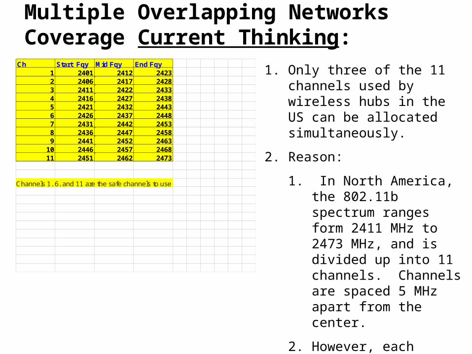
1. Only three of the 11 channels used by wireless hubs in the US can be allocated simultaneously.
2. Reason:
1. In North America, the 802.11b spectrum ranges form 2411 MHz to 2473 MHz, and is divided up into 11 channels. Channels are spaced 5 MHz apart from the center.
2. However, each channel is 22 MHz wide, so there is a great overlap
Ch Start Fqy Mid Fqy End Fqy1 2401 2412 24232 2406 2417 24283 2411 2422 24334 2416 2427 24385 2421 2432 24436 2426 2437 24487 2431 2442 24538 2436 2447 24589 2441 2452 2463
10 2446 2457 246811 2451 2462 2473
Channels 1, 6, and 11 are the safe channels to use.

An entire 22MHz is not simply swallowed up in a rectangular pattern with power on the vertical axis and frequency on the horizontal – instead it's more of a parabola, centered around the midpoint of the frequency. Thus, as you get further away from the center, the power drops off substantially. According to Burton's analysis, when three channels separate 802.11b frequencies, there is only about 4% of interference. This is the case between frequencies 1 and 4, and 8 and 11. Between 4 and 8, the interference is substantially less than 1%.
Burton’s Analysis
Access point coverage and comparison
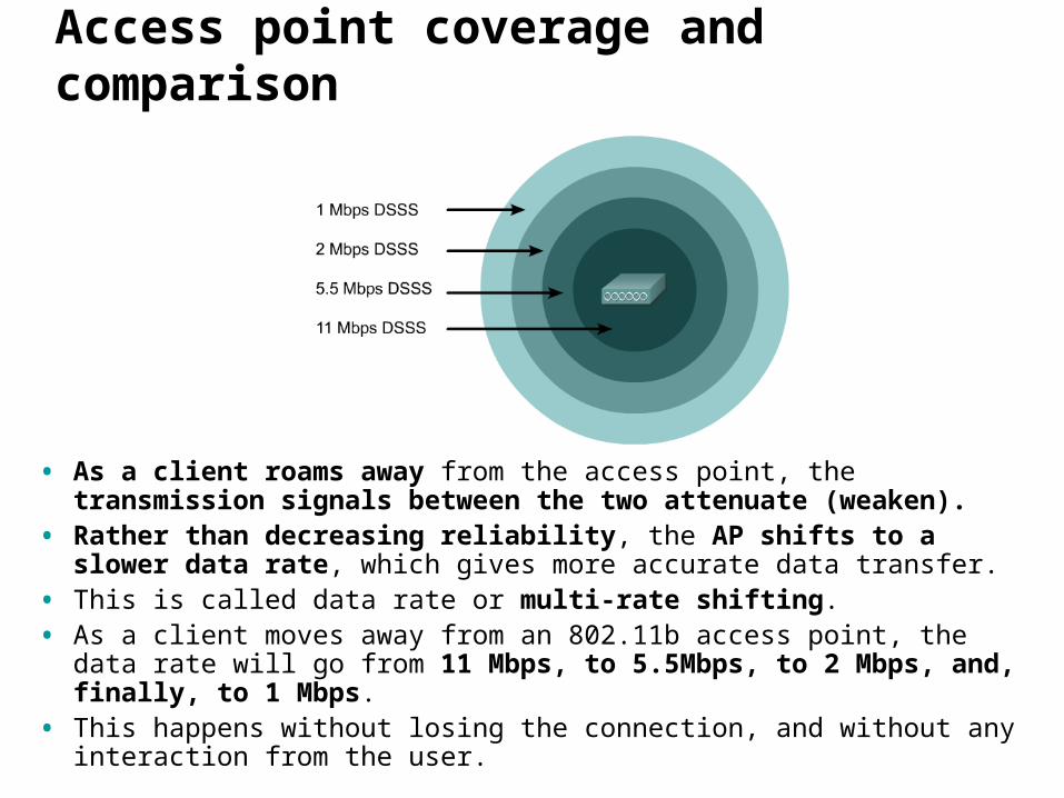
• As a client roams away from the access point, the transmission signals between the two attenuate (weaken).
• Rather than decreasing reliability, the AP shifts to a slower data rate, which gives more accurate data transfer.
• This is called data rate or multi-rate shifting. • As a client moves away from an 802.11b access point, the data rate will
go from 11 Mbps, to 5.5Mbps, to 2 Mbps, and, finally, to 1 Mbps. • This happens without losing the connection, and without any interaction
from the user.

Access point coverage and comparison
• The Cisco Aironet 2.4 GHz radio delivers 100 mW of output (AP and client) and offers a high degree of receiver sensitivity. (The power level can be decreased to 1 mw)
• The 5 GHz client radio has a 20 mW transmit power and the 5 GHz access point has a 40 mW transmit power. (The power can be decreased to 5 mw
• It is possible to adjust the power level down, to create pico-cells, or smaller coverage cells.
• This would be done, for example, to prevent the coverage area of one AP from extending too far into the coverage area of another AP.
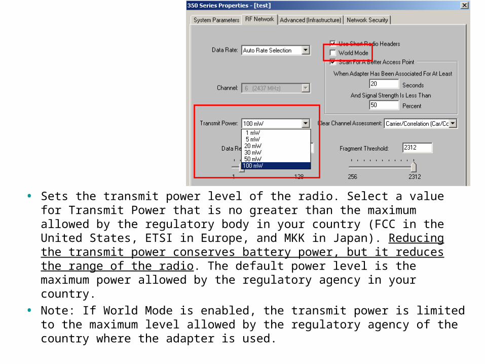
• Sets the transmit power level of the radio. Select a value for Transmit Power that is no greater than the maximum allowed by the regulatory body in your country (FCC in the United States, ETSI in Europe, and MKK in Japan). Reducing the transmit power conserves battery power, but it reduces the range of the radio. The default power level is the maximum power allowed by the regulatory agency in your country.
• Note: If World Mode is enabled, the transmit power is limited to the maximum level allowed by the regulatory agency of the country where the adapter is used.
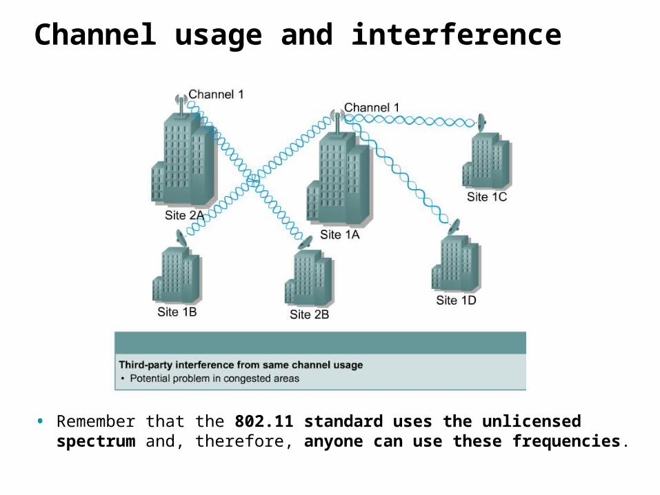
Channel usage and interference
• Remember that the 802.11 standard uses the unlicensed spectrum and, therefore, anyone can use these frequencies.

Bridge Topologies
More on Bridges Later
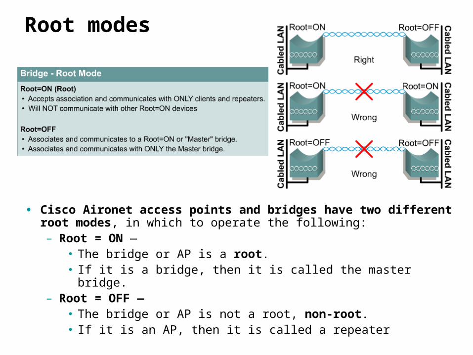
Root modes
• Cisco Aironet access points and bridges have two different root modes, in which to operate the following: – Root = ON —
• The bridge or AP is a root. • If it is a bridge, then it is called the master bridge.
– Root = OFF — • The bridge or AP is not a root, non-root. • If it is an AP, then it is called a repeater
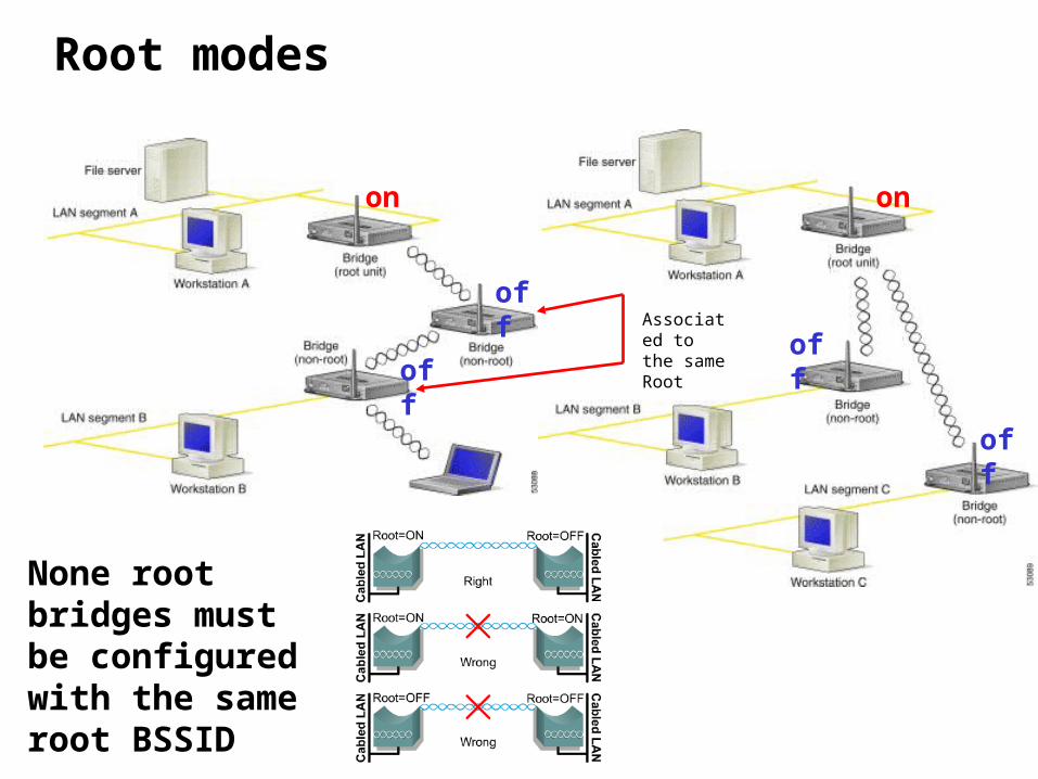
Root modes
on on
off
offoff
off
None root bridges must be configured with the same root BSSID
Associated to the same Root
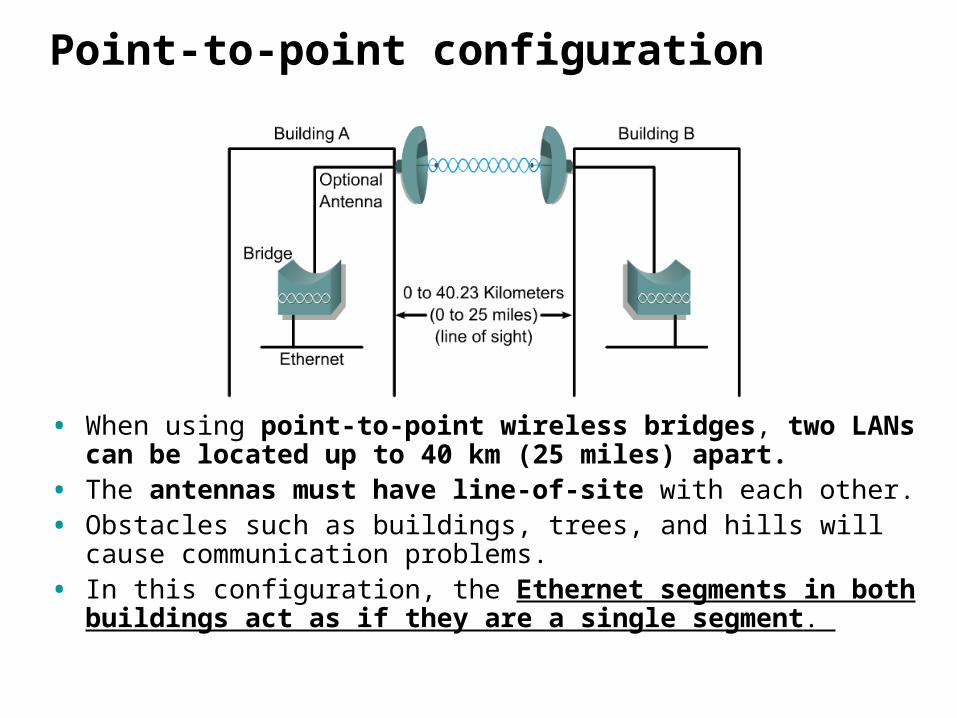
Point-to-point configuration
• When using point-to-point wireless bridges, two LANs can be located up to 40 km (25 miles) apart.
• The antennas must have line-of-site with each other. • Obstacles such as buildings, trees, and hills will cause communication
problems. • In this configuration, the Ethernet segments in both buildings act as
if they are a single segment.
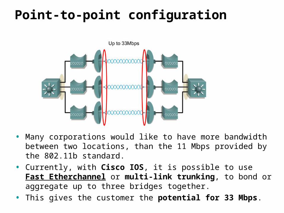
Point-to-point configuration
• Many corporations would like to have more bandwidth between two locations, than the 11 Mbps provided by the 802.11b standard.
• Currently, with Cisco IOS, it is possible to use Fast Etherchannel or multi-link trunking, to bond or aggregate up to three bridges together.
• This gives the customer the potential for 33 Mbps.
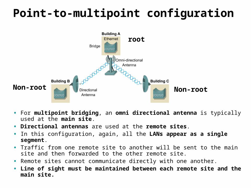
Point-to-multipoint configuration
• For multipoint bridging, an omni directional antenna is typically used at the main site.
• Directional antennas are used at the remote sites.• In this configuration, again, all the LANs appear as a single segment. • Traffic from one remote site to another will be sent to the main site and then
forwarded to the other remote site. • Remote sites cannot communicate directly with one another. • Line of sight must be maintained between each remote site and the
main site.
root
Non-root Non-root
VLAN, QoS, and Proxy Mobile IP
VLAN features
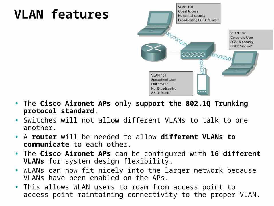
• The Cisco Aironet APs only support the 802.1Q Trunking protocol standard.
• Switches will not allow different VLANs to talk to one another. • A router will be needed to allow different VLANs to communicate to
each other. • The Cisco Aironet APs can be configured with 16 different VLANs
for system design flexibility. • WLANs can now fit nicely into the larger network because VLANs have
been enabled on the APs. • This allows WLAN users to roam from access point to access point
maintaining connectivity to the proper VLAN.
Quality of Service (QoS) feature
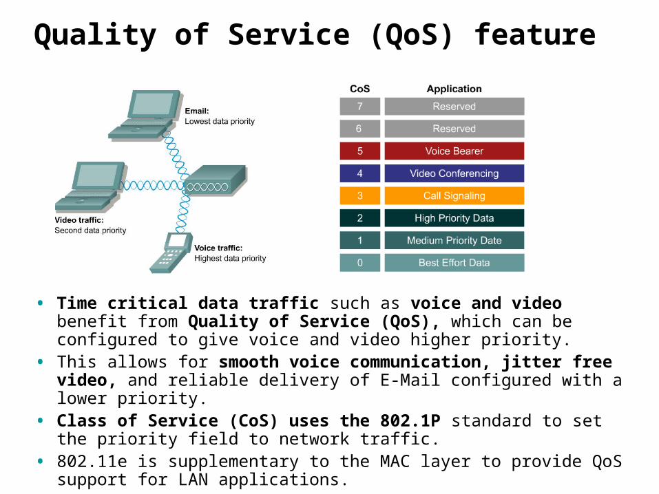
• Time critical data traffic such as voice and video benefit from Quality of Service (QoS), which can be configured to give voice and video higher priority.
• This allows for smooth voice communication, jitter free video, and reliable delivery of E-Mail configured with a lower priority.
• Class of Service (CoS) uses the 802.1P standard to set the priority field to network traffic.
• 802.11e is supplementary to the MAC layer to provide QoS support for LAN applications.
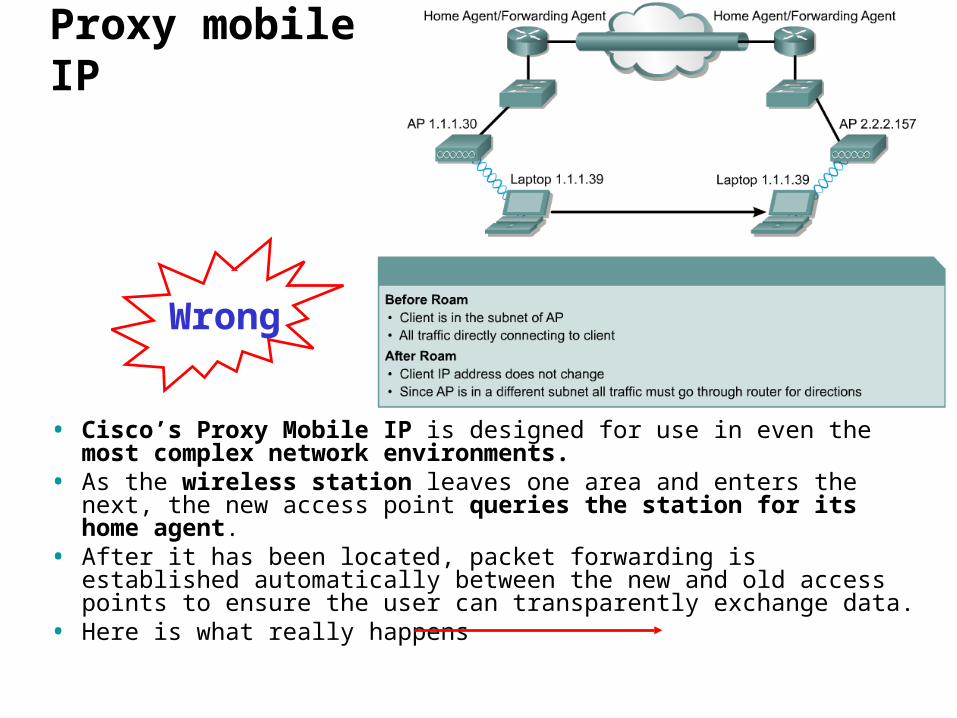
• Cisco’s Proxy Mobile IP is designed for use in even the most complex network environments.
• As the wireless station leaves one area and enters the next, the new access point queries the station for its home agent.
• After it has been located, packet forwarding is established automatically between the new and old access points to ensure the user can transparently exchange data.
• Here is what really happens
Proxy mobile IP
Wrong
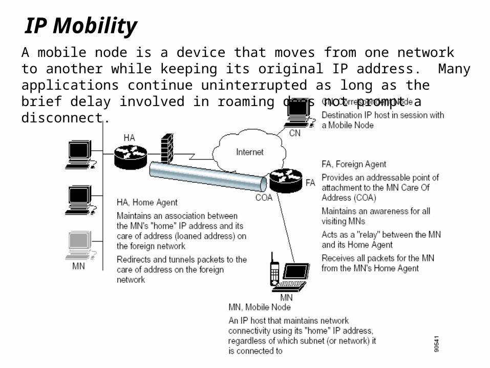
IP MobilityA mobile node is a device that moves from one network to another while keeping its original IP address. Many applications continue uninterrupted as long as the brief delay involved in roaming does not prompt a disconnect.
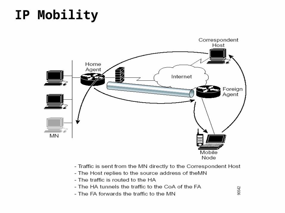
IP Mobility
Proxy Mobile IP: How It Works
• The wireless access point acts as a proxy on behalf of wireless clients that are not aware of the fact that they have roamed onto a different Layer 3 network.
• The access point handles the IRDP communications to the foreign agent and handles registrations to the home agent.
• There are three primary states of operation for proxy Mobile IP:– • Agent discovery– • Updating the subnet map table– • Device registration– • Tunneling
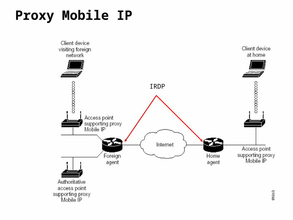
Proxy Mobile IP
IRDP