Embed Size (px)
Citation preview
1
1
Cabrillo College
Ch. 2 IP AddressingCCNP CCNP -- Advanced RoutingAdvanced Routing
Rick Graziani, Instructor(Modified presentation originally created by Mark McGregor at
Los Medanos College)Feb 5, 2002Feb 5, 2002
2
IPv4 Address Classes
Class A
Class B
Class C
Network Host Host Host
Network Network Host Host
Network Network Network Host
1st octet 2nd octet 3rd octet 4th octet
2
3
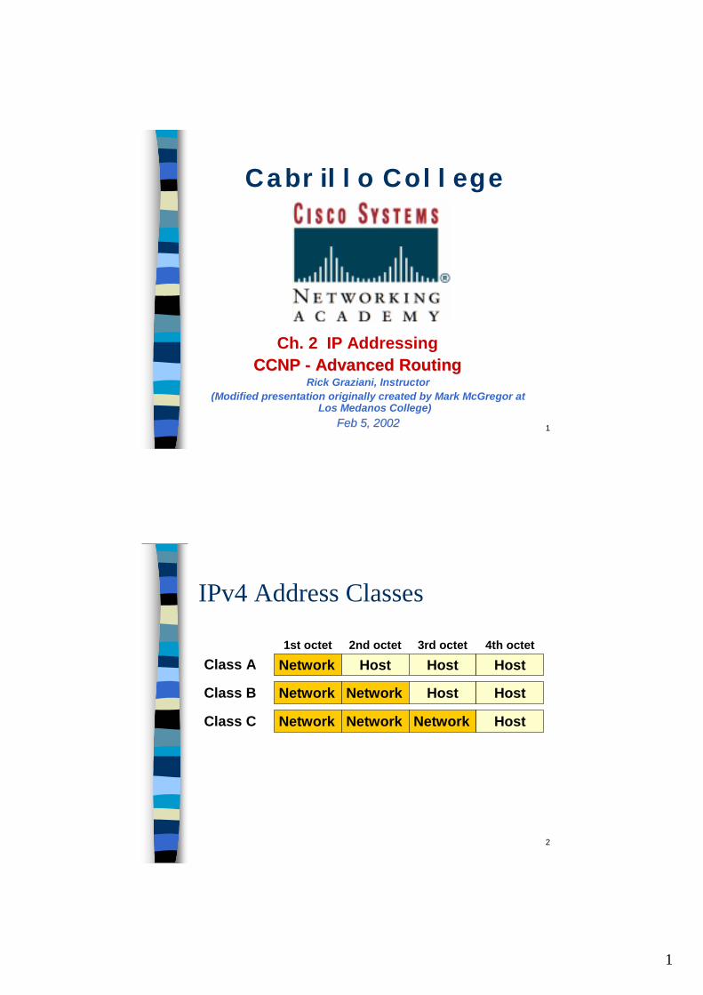
Class A addresses
Network Host Host Host
First octet is between 0 - 127
Number between 0 - 127
8 bits 8 bits 8 bits
With 24 bits available for hosts, there a 224 possible addresses. That’s 16,777,216 nodes!
■ There are 126 class A addresses.– 0 and 127 have special meaning and are not used.
■ Only large organizations such as the military, government agencies, universities, and large corporations have class A addresses.
■ Cable Modem ISPs have 24.0.0.0■ Pacbell DSL users have 63.0.0.0■ Class A addresses account for 2,147,483,648 of the possible IPv4
addresses.■ That’s 50 % of the total unicast address space!
4
Class B addresses
Network Network Host Host
First octet is between 128 - 191
Number between 128 - 191
8 bits 8 bits
With 16 bits available for hosts, there a 216 possible addresses. That’s 65,536 nodes!
■ There are 16,384 (214) class B networks.■ Class B addresses represent 25% of the total IPv4 unicast
address space.■ Class B addresses are assigned to large organizations including
corporations (such as Cisco, government agencies, and school districts).
3
5
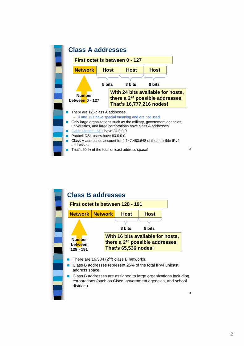
Class C addresses
Network Network Network Host
First octet is between 192 - 223
Number between 192 - 223
8 bitsWith 8 bits available for hosts, there a 28 possible addresses. That’s 256 nodes!
■ There are 2,097,152 possible class C networks.■ Class C addresses represent 12.5% of the total IPv4 unicast address
space.
6
IP address shortage■ In the early days of the Internet, IP addresses were allocated to
organizations based on request rather than actual need.■ No medium size - Hosts:
– Class A: 16 million– Class B: 65,536– Class C: 256
Subnet Mask■ The solution to the IP address shortage was thought to be the
subnet mask.■ Formalized in 1985 (RFC 950), the subnet mask breaks a single
class A, B or C network in to smaller pieces.
4
7
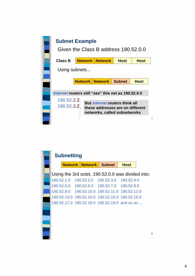
Subnet Example
Using subnets...
190.52.1.2190.52.2.2190.52.3.2
Network Network Subnet Host
But internal routers think all these addresses are on different networks, called subnetworks
Internet routers still “see” this net as 190.52.0.0
Class B Network Network Host Host
Given the Class B address 190.52.0.0
8
Subnetting
Using the 3rd octet, 190.52.0.0 was divided into:190.52.1.0 190.52.2.0 190.52.3.0 190.52.4.0 190.52.5.0 190.52.6.0 190.52.7.0 190.52.8.0 190.52.9.0 190.52.10.0 190.52.11.0 190.52.12.0 190.52.13.0 190.52.14.0 190.52.15.0 190.52.16.0 190.52.17.0 190.52.18.0 190.52.19.0 and so on ...
Network Network Subnet Host
5
9
Need a Subnet Review?
■ If you need a Review of Subnets, please review the following links on my web site:– Subnet Review (PowerPoint)– Subnets Explained (Word Doc)
10
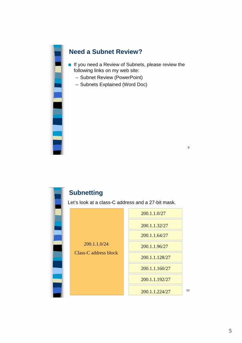
SubnettingLet’s look at a class-C address and a 27-bit mask.
200.1.1.0/24
Class-C address block
200.1.1.0/27
200.1.1.32/27
200.1.1.64/27
200.1.1.96/27
200.1.1.128/27
200.1.1.160/27
200.1.1.192/27
200.1.1.224/27
6
11
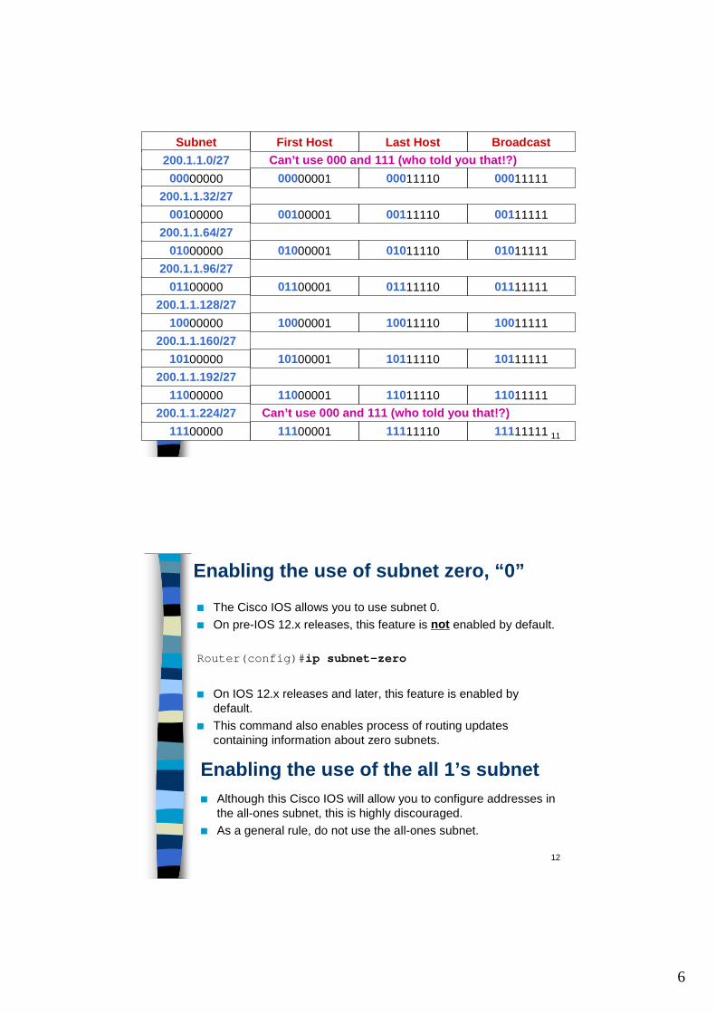
00000000 0001111100000001 00011110
Subnet BroadcastFirst Host Last Host200.1.1.0/27
00100000 0011111100100001 00111110200.1.1.32/27
01000000 0101111101000001 01011110200.1.1.64/27
01100000 0111111101100001 01111110200.1.1.96/27
10000000 1001111110000001 10011110200.1.1.128/27
10100000 1011111110100001 10111110200.1.1.160/27
11000000 1101111111000001 11011110200.1.1.192/27
11100000 1111111111100001 11111110200.1.1.224/27
Can’t use 000 and 111 (who told you that!?)
Can’t use 000 and 111 (who told you that!?)
12
Enabling the use of subnet zero, “0”■ The Cisco IOS allows you to use subnet 0. ■ On pre-IOS 12.x releases, this feature is not enabled by default.
Router(config)#ip subnet-zero
■ On IOS 12.x releases and later, this feature is enabled by default.
■ This command also enables process of routing updates containing information about zero subnets.
Enabling the use of the all 1’s subnet■ Although this Cisco IOS will allow you to configure addresses in
the all-ones subnet, this is highly discouraged.■ As a general rule, do not use the all-ones subnet.
7
13
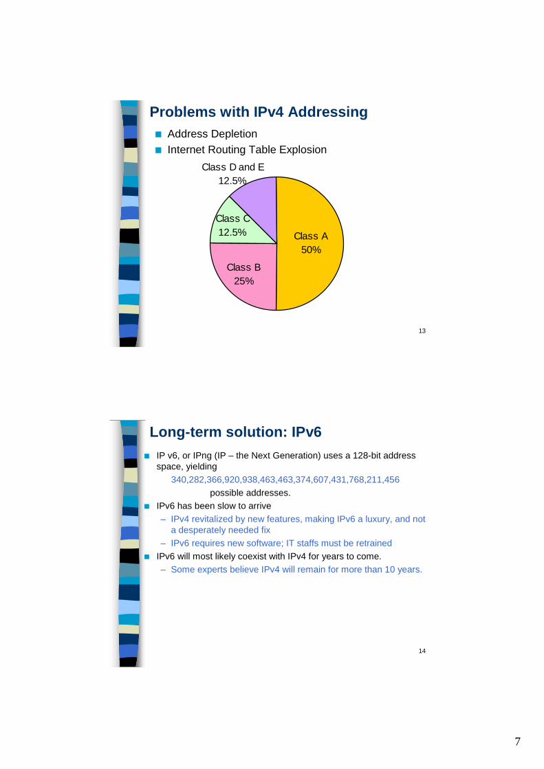
Problems with IPv4 Addressing■ Address Depletion■ Internet Routing Table Explosion
Class D and E12.5%
Class C12.5% Class A
50%
Class B25%
14
Long-term solution: IPv6■ IP v6, or IPng (IP – the Next Generation) uses a 128-bit address
space, yielding340,282,366,920,938,463,463,374,607,431,768,211,456
possible addresses.■ IPv6 has been slow to arrive
– IPv4 revitalized by new features, making IPv6 a luxury, and not a desperately needed fix
– IPv6 requires new software; IT staffs must be retrained■ IPv6 will most likely coexist with IPv4 for years to come.
– Some experts believe IPv4 will remain for more than 10 years.
8
15
IPv6 Address format - FYI■ Unicast: An identifier for a single interface.■ Anycast: An identifier for a set of interfaces (typically belonging to
different nodes). A packet sent to an anycast address is delivered to the “nearest,” or first, interface in the anycast group.– A mechanism for addressing multiple interfaces, usually on different
nodes, with the same IP address Traffic destined to the address gets routed to the nearest node.” Jeff Doyle
Searchnetworking.com– In Internet Protocol Version 6 (IPv6), anycast is communication
between a single sender and the nearest of several receivers in a group. The term exists in contradistinction to multicast, communication between a single sender and multiple receivers, and unicast, communication between a single sender and a single receiver in a network.
– Anycasting is designed to let one host initiate the efficient updating of router tables for a group of hosts. IPv6 can determine which gateway host is closest and sends the packets to that host as though it were a unicast communication. In turn, that host can anycast to another host in the group until all routing tables are updated.
■ Multicast: An identifier for a set of interfaces (typically belonging to different nodes). A packet sent to a multicast address is delivered to all interfaces in the multicast group.
16
IPv6 address format - FYI■ IPv6 can be written as 32 hex digits, with colons separating the
values of the eight 16-bit pieces of the address:FEDC:BA98:7654:3210:FEDC:BA98:7654:3210
■ This example address shows that leading zeros in each 16-bit value can be omitted:
1080:0:0:0:8:800:200C:417A
■ Because IPv6 addresses, especially in the early implementation phase, may contain consecutive 16-bit values of zero, one such string of 0s per address can be omitted and replaced by a double colon, so this:
1080:0:0:0:8:800:200C:417Acan be shortened to become this:
1080::8:800:200C:417A
■ The IPv6 loopback address0:0:0:0:0:0:0:1
This can be written as this:::1
9
17
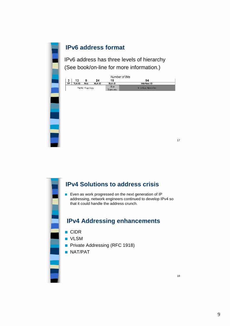
IPv6 address format
IPv6 address has three levels of hierarchy(See book/on-line for more information.)
18
IPv4 Solutions to address crisis■ Even as work progressed on the next generation of IP
addressing, network engineers continued to develop IPv4 so that it could handle the address crunch.
IPv4 Addressing enhancements■ CIDR■ VLSM■ Private Addressing (RFC 1918)■ NAT/PAT
10
19
CIDR - Classless Interdomain Routing■ Note: We will visit CIDR again when we discuss BGP and how
it help reduced the Internet routing table explosion.– We will also see of the difficulties CIDR presents to anyone
wishing to connect to multiple service providers or wishing more portability with their address space.
■ Classless Interdomain Routing– “classless IP”– pronounced “cider”
■ To CIDR-compliant routers, address class is meaningless. – The network portion of the address is determine by network
prefix (/8, /19, etc.)– The network address is NOT determined by the first octet
(first two bits).– 200.10.0.0/16 or 15.10.160.0/19
20
CIDR and Route Summarization■ First deployed in 1994, CIDR dramatically improves IPv4’s scalability
and efficiency by providing the following:– The replacement of classful addressing with a more flexible and
less wasteful classes scheme (VLSM)– Enhanced route aggregation (summarization), also known as
supernetting ■ CIDR allows routers to aggregate, or summarize, routing
information and thus shrink the size of their routing tables. – Just one address and mask combination can represent the
routes to multiple networks.– Used by IGP routers within an AS and EGP routers between
AS. ■ We will see how this benefits the Internet (EGP routers), i.e.
Network Service Providers, Regional Service Providers, and ISPs later when we address BGP.
11
21
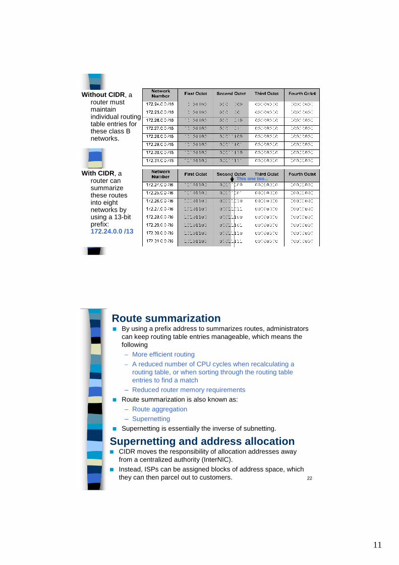
Without CIDR, a router must maintain individual routing table entries for these class B networks.
With CIDR, a router can summarize these routes into eight networks by using a 13-bit prefix: 172.24.0.0 /13
This one too...
22
Route summarization■ By using a prefix address to summarizes routes, administrators
can keep routing table entries manageable, which means the following– More efficient routing– A reduced number of CPU cycles when recalculating a
routing table, or when sorting through the routing table entries to find a match
– Reduced router memory requirements■ Route summarization is also known as:
– Route aggregation– Supernetting
■ Supernetting is essentially the inverse of subnetting.
Supernetting and address allocation■ CIDR moves the responsibility of allocation addresses away
from a centralized authority (InterNIC).■ Instead, ISPs can be assigned blocks of address space, which
they can then parcel out to customers.
12
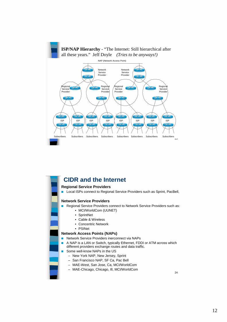
23Subscribers Subscribers Subscribers Subscribers Subscribers Subscribers Subscribers Subscribers
ISP ISP ISP ISP ISP ISP ISP ISP
RegionalServiceProvider
RegionalServiceProvider
RegionalServiceProvider
RegionalServiceProvider
NetworkServiceProvider
NetworkServiceProvider
NAP (Network Access Point)
ISP/NAP Hierarchy - “The Internet: Still hierarchical after all these years.” Jeff Doyle (Tries to be anyways!)
24
CIDR and the InternetRegional Service Providers■ Local ISPs connect to Regional Service Providers such as Sprint, PacBell,
Network Service Providers■ Regional Service Providers connect to Network Service Providers such as:
• MCI/WorldCom (UUNET)• SprintNet• Cable & Wireless• Concentric Network• PSINet
Network Access Points (NAPs)■ Network Service Providers inerconnect via NAPs■ A NAP is a LAN or Switch, typically Ethernet, FDDI or ATM across which
different providers exchange routes and data traffic.■ Some well-know NAPs in the US
– New York NAP, New Jersey, Sprint– San Francisco NAP, SF Ca, Pac Bell– MAE-West, San Jose, Ca, MCI/WorldCom– MAE-Chicago, Chicago, Ill, MCI/WorldCom
13
25
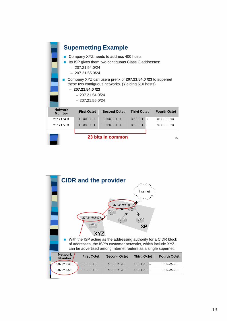
Supernetting Example■ Company XYZ needs to address 400 hosts. ■ Its ISP gives them two contiguous Class C addresses:
– 207.21.54.0/24– 207.21.55.0/24
■ Company XYZ can use a prefix of 207.21.54.0 /23 to supernet these two contiguous networks. (Yielding 510 hosts)– 207.21.54.0 /23
– 207.21.54.0/24– 207.21.55.0/24
23 bits in common
26
CIDR and the provider
■ With the ISP acting as the addressing authority for a CIDR blockof addresses, the ISP’s customer networks, which include XYZ, can be advertised among Internet routers as a single supernet.
14
27
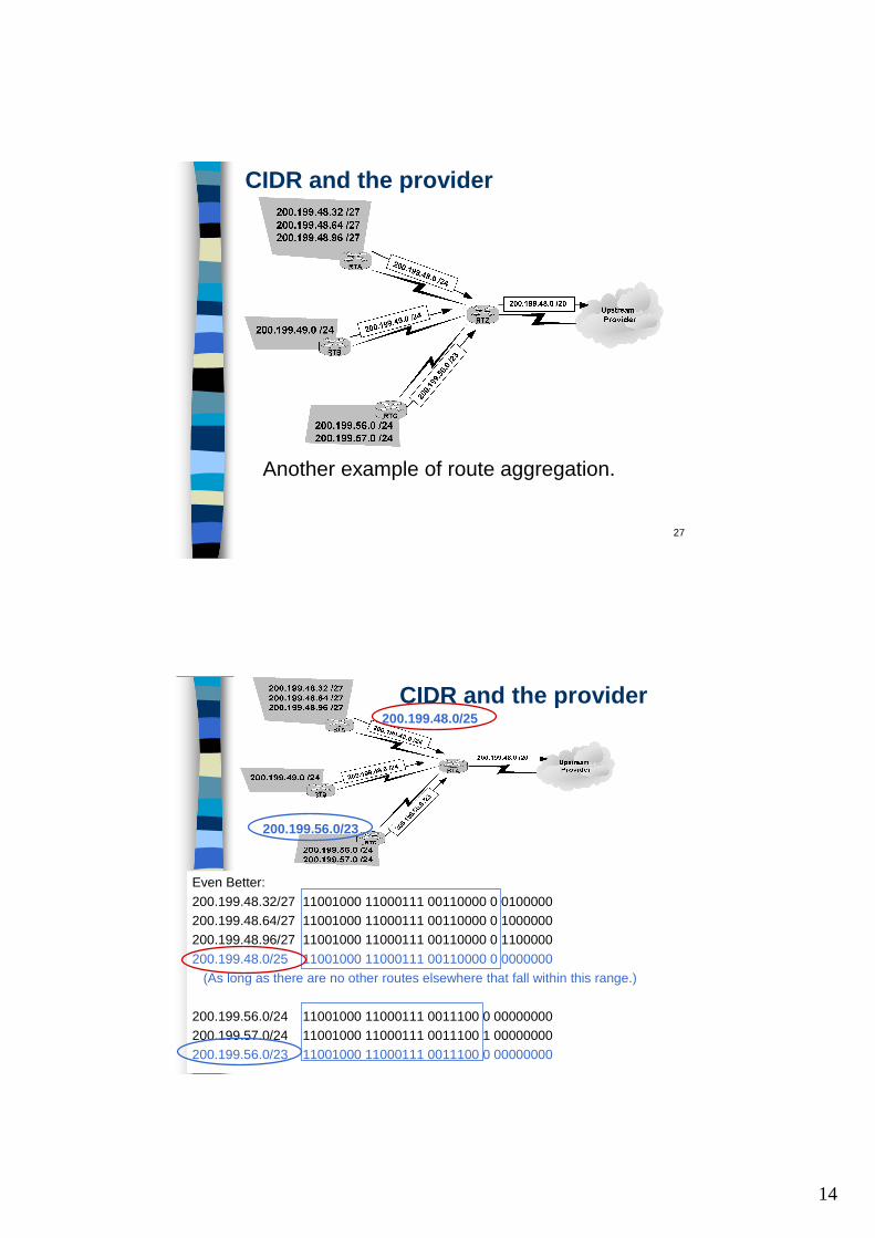
CIDR and the provider
Another example of route aggregation.
28
Even Better:200.199.48.32/27 11001000 11000111 00110000 0 0100000200.199.48.64/27 11001000 11000111 00110000 0 1000000200.199.48.96/27 11001000 11000111 00110000 0 1100000200.199.48.0/25 11001000 11000111 00110000 0 0000000
(As long as there are no other routes elsewhere that fall within this range.)
200.199.56.0/24 11001000 11000111 0011100 0 00000000200.199.57.0/24 11001000 11000111 0011100 1 00000000200.199.56.0/23 11001000 11000111 0011100 0 00000000
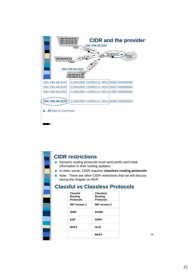
CIDR and the provider200.199.48.0/25
200.199.56.0/23
15
29
CIDR and the provider200.199.48.0/25
200.199.56.0/23
200.199.48.0/25 11001000 11000111 0011 0000 00000000 200.199.49.0/25 11001000 11000111 0011 0001 00000000 200.199.56.0/23 11001000 11000111 0011 1000 00000000
200.199.48.0/20 11001000 11000111 0011 0000 00000000
■ 20 bits in common
30
CIDR restrictions■ Dynamic routing protocols must send prefix and mask
information in their routing updates.■ In other words, CIDR requires classless routing protocols.■ Note: There are other CIDR restrictions that we will discuss
during the chapter on BGP.
Classful vs Classless ProtocolsClassfulRouting Protocols
Classless Routing Protocols
RIP version 1 RIP version 2
IGRP EIGRP
EGP OSPF
BGP3 IS-IS
BGP4
16
31
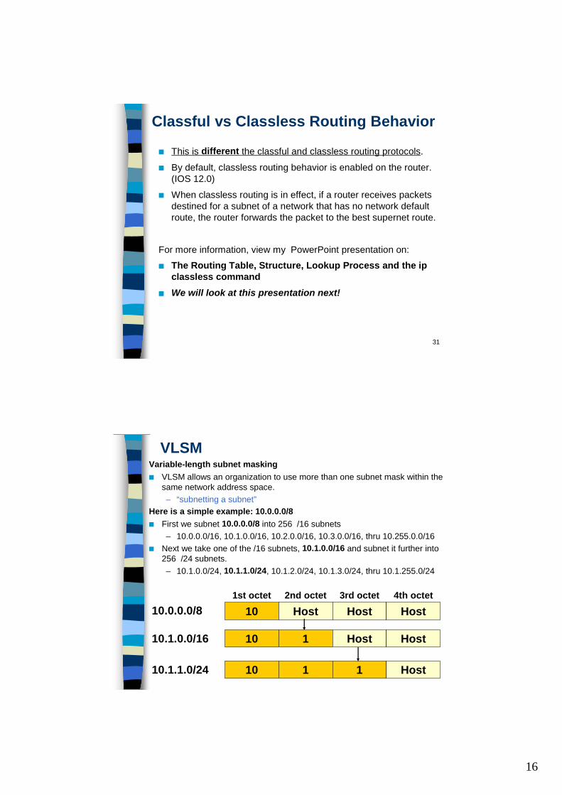
Classful vs Classless Routing Behavior
■ This is different the classful and classless routing protocols.■ By default, classless routing behavior is enabled on the router.
(IOS 12.0)■ When classless routing is in effect, if a router receives packets
destined for a subnet of a network that has no network default route, the router forwards the packet to the best supernet route.
For more information, view my PowerPoint presentation on:■ The Routing Table, Structure, Lookup Process and the ip
classless command■ We will look at this presentation next!
32
VLSMVariable-length subnet masking■ VLSM allows an organization to use more than one subnet mask within the
same network address space. – “subnetting a subnet”
Here is a simple example: 10.0.0.0/8■ First we subnet 10.0.0.0/8 into 256 /16 subnets
– 10.0.0.0/16, 10.1.0.0/16, 10.2.0.0/16, 10.3.0.0/16, thru 10.255.0.0/16■ Next we take one of the /16 subnets, 10.1.0.0/16 and subnet it further into
256 /24 subnets.– 10.1.0.0/24, 10.1.1.0/24, 10.1.2.0/24, 10.1.3.0/24, thru 10.1.255.0/24
10.0.0.0/8
10.1.0.0/16
10.1.1.0/24
10 Host Host Host
10 1 Host Host
10 1 1 Host
1st octet 2nd octet 3rd octet 4th octet
17
33
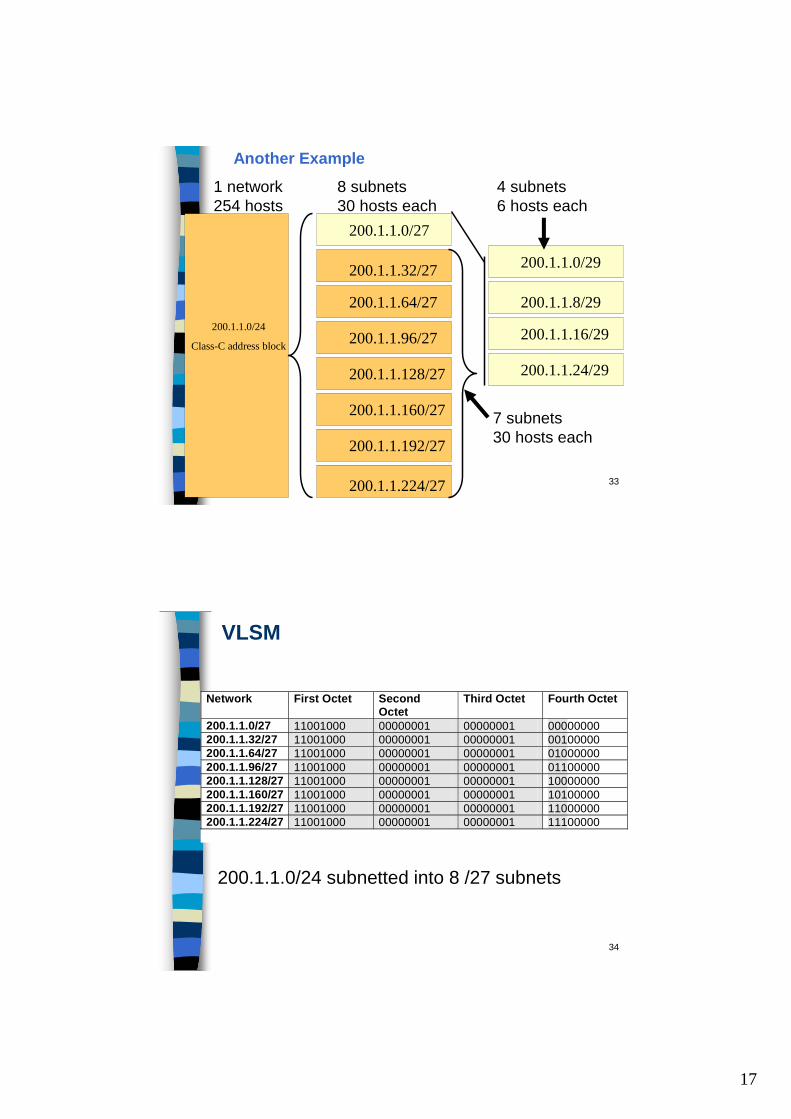
200.1.1.0/24
Class-C address block
200.1.1.0/27
200.1.1.32/27
200.1.1.64/27
200.1.1.96/27
200.1.1.128/27
200.1.1.160/27
200.1.1.192/27
200.1.1.224/27
200.1.1.0/29
200.1.1.8/29
200.1.1.16/29
200.1.1.24/29
1 network 254 hosts
8 subnets 30 hosts each
4 subnets 6 hosts each
7 subnets 30 hosts each
Another Example
34
200.1.1.0/24 subnetted into 8 /27 subnets
VLSM
Network First Octet Second Octet
Third Octet Fourth Octet
200.1.1.0/27 11001000 00000001 00000001 00000000 200.1.1.32/27 11001000 00000001 00000001 00100000 200.1.1.64/27 11001000 00000001 00000001 01000000 200.1.1.96/27 11001000 00000001 00000001 01100000 200.1.1.128/27 11001000 00000001 00000001 10000000 200.1.1.160/27 11001000 00000001 00000001 10100000 200.1.1.192/27 11001000 00000001 00000001 11000000 200.1.1.224/27 11001000 00000001 00000001 11100000
18
35
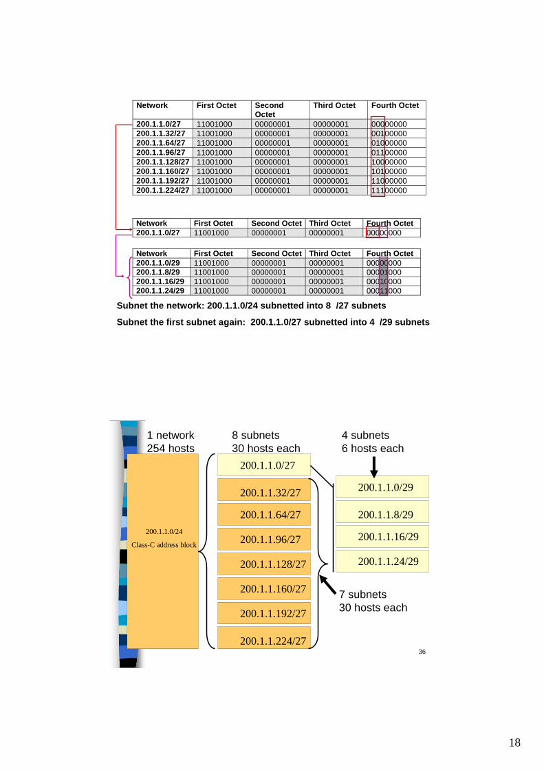
Network First Octet Second Octet Third Octet Fourth Octet 200.1.1.0/27 11001000 00000001 00000001 00000000 Network First Octet Second Octet Third Octet Fourth Octet 200.1.1.0/29 11001000 00000001 00000001 00000000 200.1.1.8/29 11001000 00000001 00000001 00001000 200.1.1.16/29 11001000 00000001 00000001 00010000 200.1.1.24/29 11001000 00000001 00000001 00011000 Subnet the network: 200.1.1.0/24 subnetted into 8 /27 subnets
Subnet the first subnet again: 200.1.1.0/27 subnetted into 4 /29 subnets
Network First Octet Second Octet
Third Octet Fourth Octet
200.1.1.0/27 11001000 00000001 00000001 00000000 200.1.1.32/27 11001000 00000001 00000001 00100000 200.1.1.64/27 11001000 00000001 00000001 01000000 200.1.1.96/27 11001000 00000001 00000001 01100000 200.1.1.128/27 11001000 00000001 00000001 10000000 200.1.1.160/27 11001000 00000001 00000001 10100000 200.1.1.192/27 11001000 00000001 00000001 11000000 200.1.1.224/27 11001000 00000001 00000001 11100000
36
200.1.1.0/24
Class-C address block
200.1.1.0/27
200.1.1.32/27
200.1.1.64/27
200.1.1.96/27
200.1.1.128/27
200.1.1.160/27
200.1.1.192/27
200.1.1.224/27
200.1.1.0/29
200.1.1.8/29
200.1.1.16/29
200.1.1.24/29
1 network 254 hosts
8 subnets 30 hosts each
4 subnets 6 hosts each
7 subnets 30 hosts each
19
37
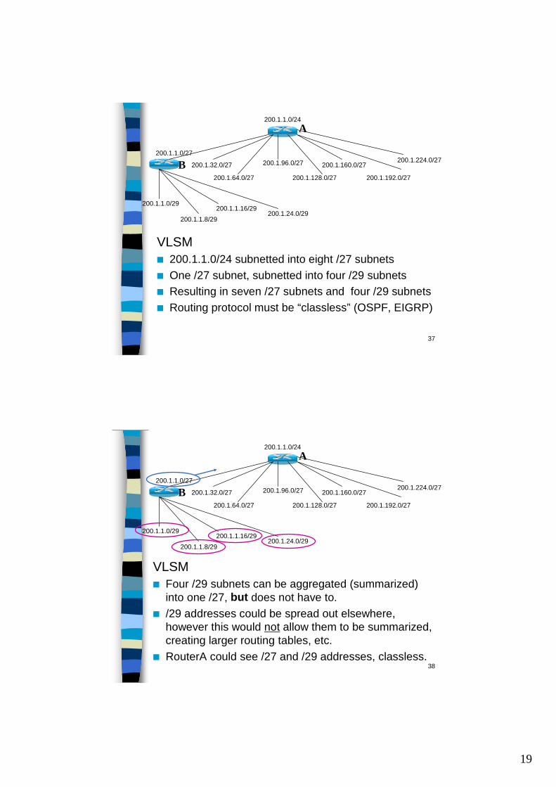
VLSM■ 200.1.1.0/24 subnetted into eight /27 subnets■ One /27 subnet, subnetted into four /29 subnets■ Resulting in seven /27 subnets and four /29 subnets■ Routing protocol must be “classless” (OSPF, EIGRP)
200.1.1.0/24
200.1.1.0/27
200.1.32.0/27
200.1.64.0/27
200.1.96.0/27
200.1.128.0/27
200.1.160.0/27
200.1.192.0/27
200.1.224.0/27
200.1.1.0/29
200.1.1.8/29200.1.1.16/29
200.1.24.0/29
A
B
38
VLSM■ Four /29 subnets can be aggregated (summarized)
into one /27, but does not have to. ■ /29 addresses could be spread out elsewhere,
however this would not allow them to be summarized, creating larger routing tables, etc.
■ RouterA could see /27 and /29 addresses, classless.
200.1.1.0/24
200.1.1.0/27
200.1.32.0/27
200.1.64.0/27
200.1.96.0/27
200.1.128.0/27
200.1.160.0/27
200.1.192.0/27
200.1.224.0/27
200.1.1.0/29
200.1.1.8/29200.1.1.16/29
200.1.24.0/29
A
B
20
39
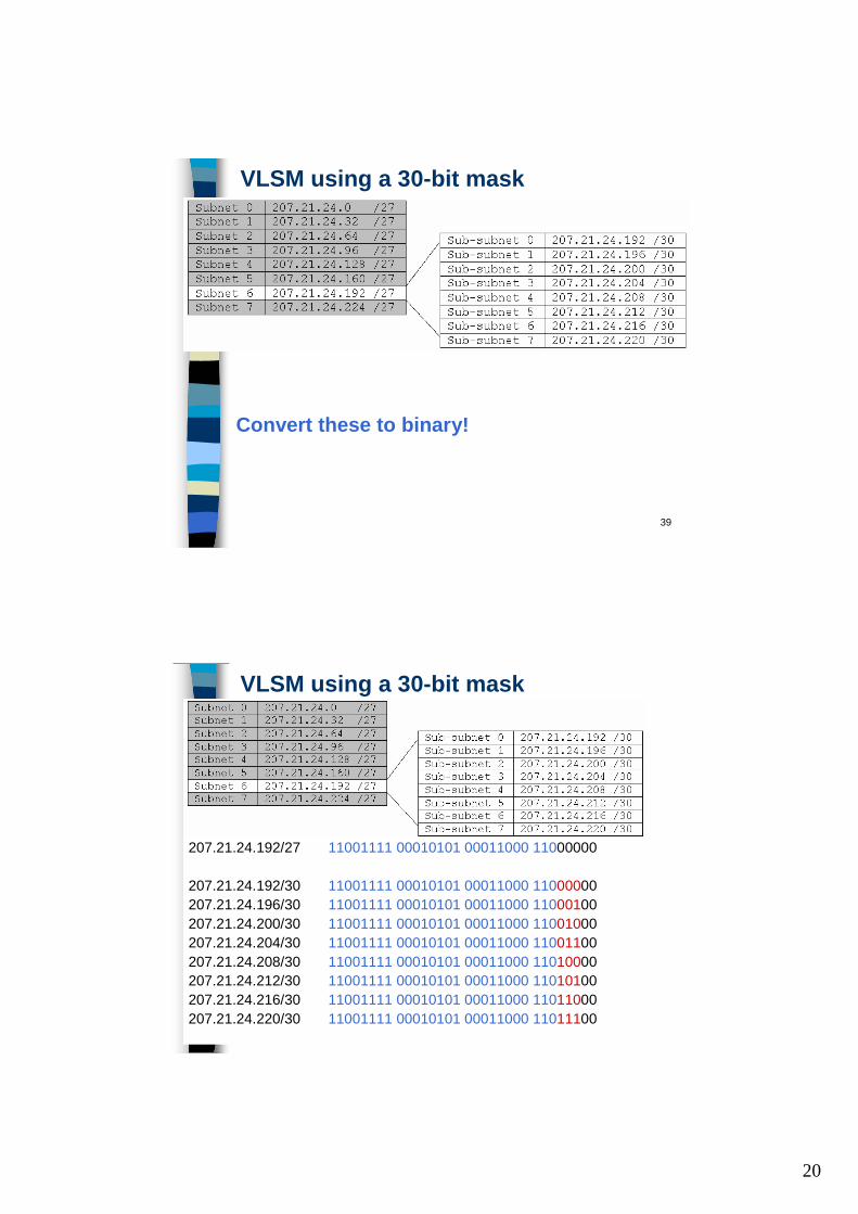
VLSM using a 30-bit mask
Convert these to binary!
40
VLSM using a 30-bit mask
207.21.24.192/27 11001111 00010101 00011000 11000000
207.21.24.192/30 11001111 00010101 00011000 11000000207.21.24.196/30 11001111 00010101 00011000 11000100207.21.24.200/30 11001111 00010101 00011000 11001000207.21.24.204/30 11001111 00010101 00011000 11001100207.21.24.208/30 11001111 00010101 00011000 11010000207.21.24.212/30 11001111 00010101 00011000 11010100207.21.24.216/30 11001111 00010101 00011000 11011000207.21.24.220/30 11001111 00010101 00011000 11011100
21
41
VLSM using a 30-bit mask
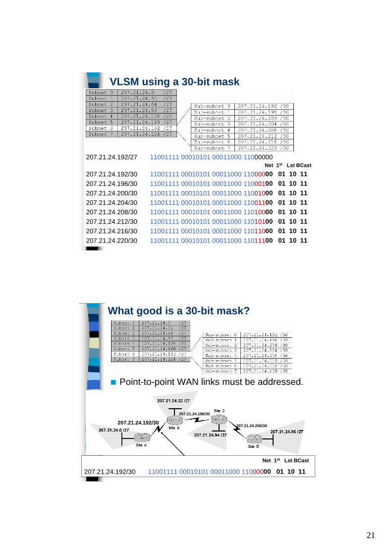
207.21.24.192/27 11001111 00010101 00011000 11000000Net 1st Lst BCast
207.21.24.192/30 11001111 00010101 00011000 11000000 01 10 11207.21.24.196/30 11001111 00010101 00011000 11000100 01 10 11207.21.24.200/30 11001111 00010101 00011000 11001000 01 10 11207.21.24.204/30 11001111 00010101 00011000 11001100 01 10 11207.21.24.208/30 11001111 00010101 00011000 11010000 01 10 11207.21.24.212/30 11001111 00010101 00011000 11010100 01 10 11207.21.24.216/30 11001111 00010101 00011000 11011000 01 10 11207.21.24.220/30 11001111 00010101 00011000 11011100 01 10 11
42
What good is a 30-bit mask?
■ Point-to-point WAN links must be addressed.
207.21.24.192/30207.21.24.196/30
207.21.24.200/30
Net 1st Lst BCast
207.21.24.192/30 11001111 00010101 00011000 11000000 01 10 11
22
43
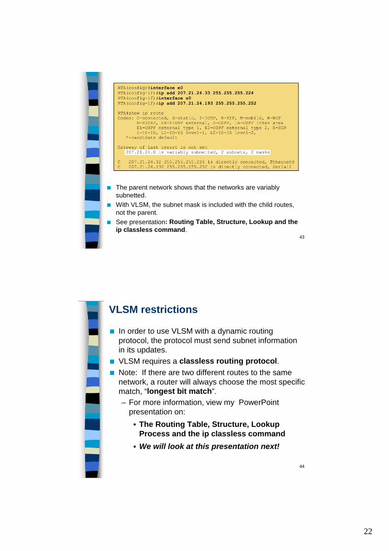
■ The parent network shows that the networks are variably subnetted.
■ With VLSM, the subnet mask is included with the child routes, not the parent.
■ See presentation: Routing Table, Structure, Lookup and theip classless command.
44
VLSM restrictions
■ In order to use VLSM with a dynamic routing protocol, the protocol must send subnet information in its updates.
■ VLSM requires a classless routing protocol.■ Note: If there are two different routes to the same
network, a router will always choose the most specific match, “longest bit match”.– For more information, view my PowerPoint
presentation on:• The Routing Table, Structure, Lookup
Process and the ip classless command• We will look at this presentation next!
23
45
Alternative Point-To-Point Addressing■ VLSM is often used to create 2-host networks for point-to-point
links. ■ Other solutions include:
– IP unnumbered (RFC 1812)– Private addressing (RFC 1918)
IP Unnumbered – RFC 1812■ When a serial interface is configured for IP unnumbered, it
borrows the IP address of another interface (usually a LAN interface) and therefore does not need its own address.
■ Not only does IP unnumbered avoid wasting addresses on point-to-point WAN links, it can also be used with classful routing protocols.
■ If your network runs RIPv1 or IGRP, IP unnumbered may be the only solution to maximize your addresses.
46
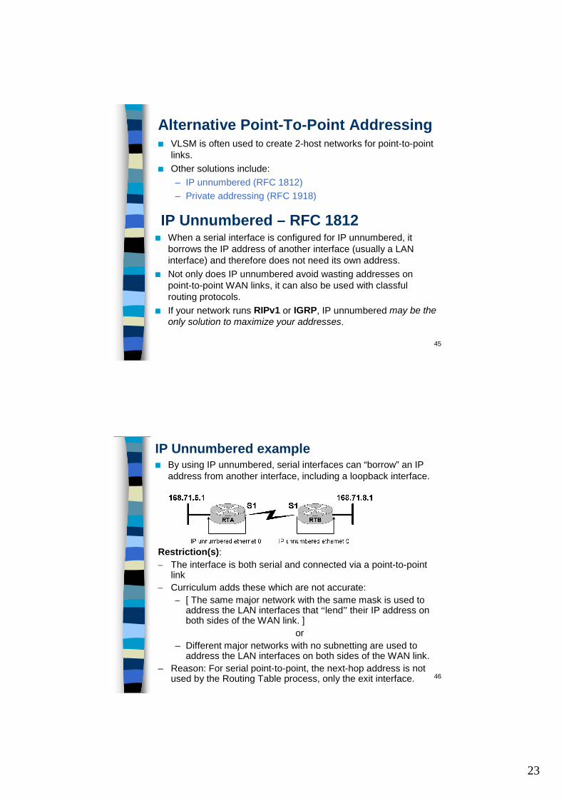
IP Unnumbered example■ By using IP unnumbered, serial interfaces can “borrow” an IP
address from another interface, including a loopback interface.
Restriction(s):– The interface is both serial and connected via a point-to-point
link– Curriculum adds these which are not accurate:
– [ The same major network with the same mask is used to address the LAN interfaces that “lend” their IP address on both sides of the WAN link. ]
or– Different major networks with no subnetting are used to
address the LAN interfaces on both sides of the WAN link.– Reason: For serial point-to-point, the next-hop address is not
used by the Routing Table process, only the exit interface.
24
47
Using IP unnumbered is not without its drawbacks, which include the following:
■ You cannot use ping to determine whether the interface is up because the interface has no IP address.
■ You cannot boot from a network IOS image over an unnumbered serial interface.
■ You cannot support IP security options on an unnumbered interface.
IP Unnumbered drawbacks
48
Class RFC 1918 Internal Address Range
CIDR Prefix
A 10.0.0.0 –10.255.255.255
10.0.0.0 /8
B 172.16.0.0 –172.31.255.255
172.16.0.0 /12
C 192.168.0.0 –192.168.255.255
192.168.0.0 /16
Private Addressing
■ RFC 1918 specifies reserved ranges of IP addresses to be used for internal networks only.
■ These address ranges will not (should not) be routed out on the Internet.– ISPs normally filter out these addresses, on both an outgoing and
incoming basis to filter out 1918 address space from leaking into other autonomous systems.
■ If you are addressing a non-public intranet, a test lab, or a home network, these private addressed can be used instead of globally unique addresses, which must be obtained from a provider or registry at some expense.
25
49
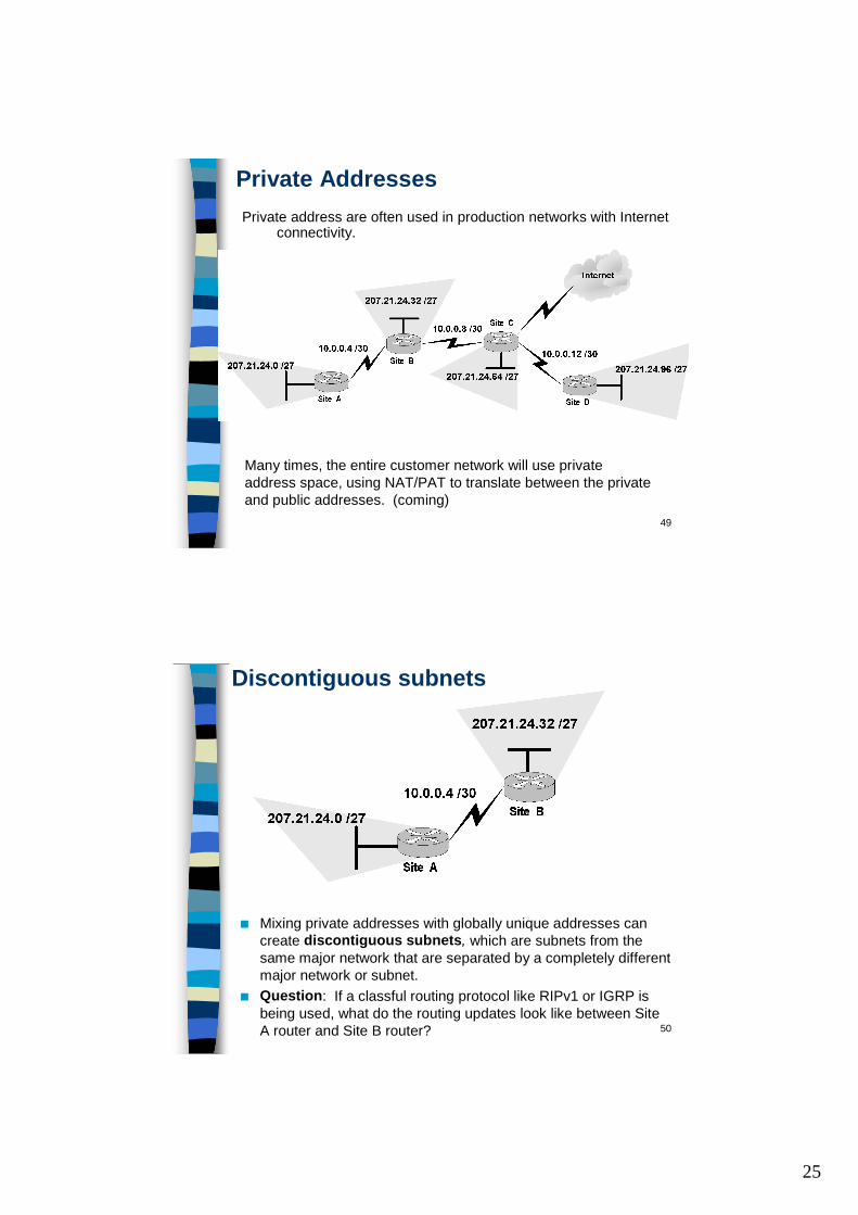
Private AddressesPrivate address are often used in production networks with Internet
connectivity.
Many times, the entire customer network will use private address space, using NAT/PAT to translate between the private and public addresses. (coming)
50
Discontiguous subnets
■ Mixing private addresses with globally unique addresses can create discontiguous subnets, which are subnets from the same major network that are separated by a completely different major network or subnet.
■ Question: If a classful routing protocol like RIPv1 or IGRP is being used, what do the routing updates look like between Site A router and Site B router?
26
51
Discontiguous subnets
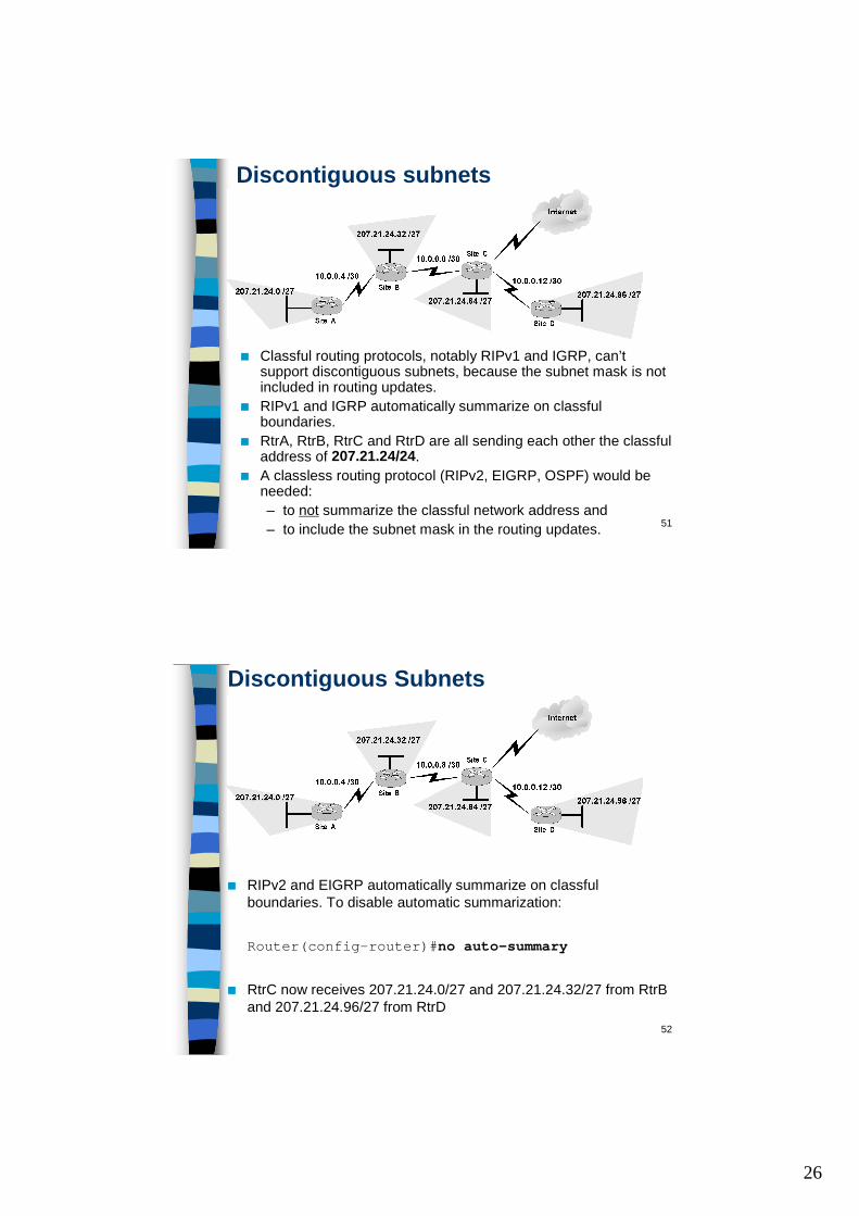
■ Classful routing protocols, notably RIPv1 and IGRP, can’t support discontiguous subnets, because the subnet mask is not included in routing updates.
■ RIPv1 and IGRP automatically summarize on classful boundaries.
■ RtrA, RtrB, RtrC and RtrD are all sending each other the classful address of 207.21.24/24.
■ A classless routing protocol (RIPv2, EIGRP, OSPF) would be needed:– to not summarize the classful network address and – to include the subnet mask in the routing updates.
52
Discontiguous Subnets
■ RIPv2 and EIGRP automatically summarize on classful boundaries. To disable automatic summarization:
Router(config-router)#no auto-summary
■ RtrC now receives 207.21.24.0/27 and 207.21.24.32/27 from RtrB and 207.21.24.96/27 from RtrD
27
53
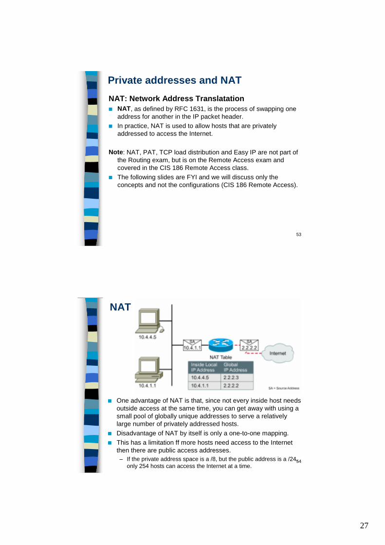
Private addresses and NATNAT: Network Address Translatation■ NAT, as defined by RFC 1631, is the process of swapping one
address for another in the IP packet header. ■ In practice, NAT is used to allow hosts that are privately
addressed to access the Internet.
Note: NAT, PAT, TCP load distribution and Easy IP are not part of the Routing exam, but is on the Remote Access exam and covered in the CIS 186 Remote Access class.
■ The following slides are FYI and we will discuss only the concepts and not the configurations (CIS 186 Remote Access).
54
NAT
■ One advantage of NAT is that, since not every inside host needs outside access at the same time, you can get away with using a small pool of globally unique addresses to serve a relatively large number of privately addressed hosts.
■ Disadvantage of NAT by itself is only a one-to-one mapping.■ This has a limitation ff more hosts need access to the Internet
then there are public access addresses.– If the private address space is a /8, but the public address is a /24,
only 254 hosts can access the Internet at a time.
28
55
NAT■ Because outside hosts never see the “pre-translated” inside
addresses, NAT has the effect of hiding the inside structureof a network.
■ Although NAT is not a security firewall, it can prevent outsiders from connecting directly to inside hosts, unless a permanent global address mapping exists in the NAT table.
■ If you actually wants outside users to access an internally addressed webserver, you can statically map a global address (2.2.2.3) to an inside address (10.0.0.1).– Static mappings exist in the NAT table until they are
removed by an administrator. – Internet hosts, and DNS, can use the global address to
access the privately addressed webserver.■ Since CIDR places the authority to assign addresses at the ISP
level, if you moved from one ISP to another, your company may have to completely readdress its systems with the new ISP’s CIDR block. – Instead of readdressing, NAT can be deployed to temporarily
translate the old addresses to new ones, with static mappings in place to keep web and other public services available to the outside
56
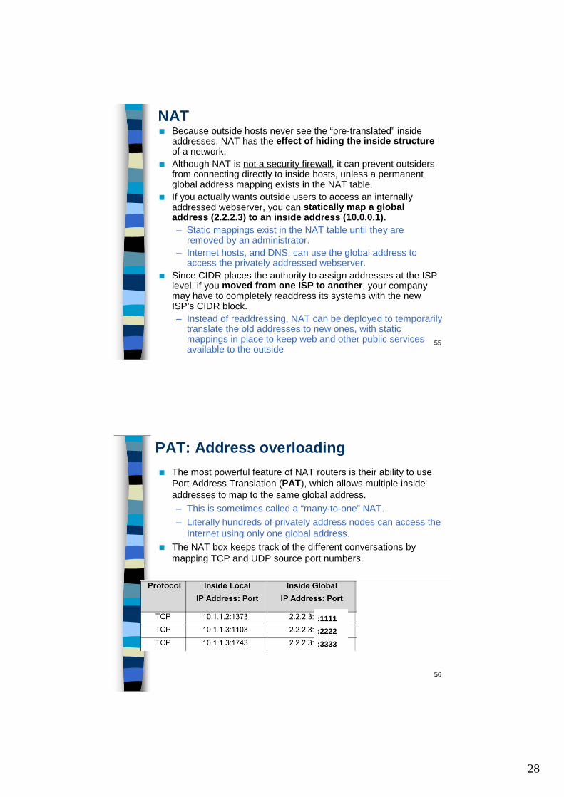
PAT: Address overloading■ The most powerful feature of NAT routers is their ability to use
Port Address Translation (PAT), which allows multiple inside addresses to map to the same global address. – This is sometimes called a “many-to-one” NAT. – Literally hundreds of privately address nodes can access the
Internet using only one global address.■ The NAT box keeps track of the different conversations by
mapping TCP and UDP source port numbers.
:1111 :2222 :3333
29
57
TCP Load distribution
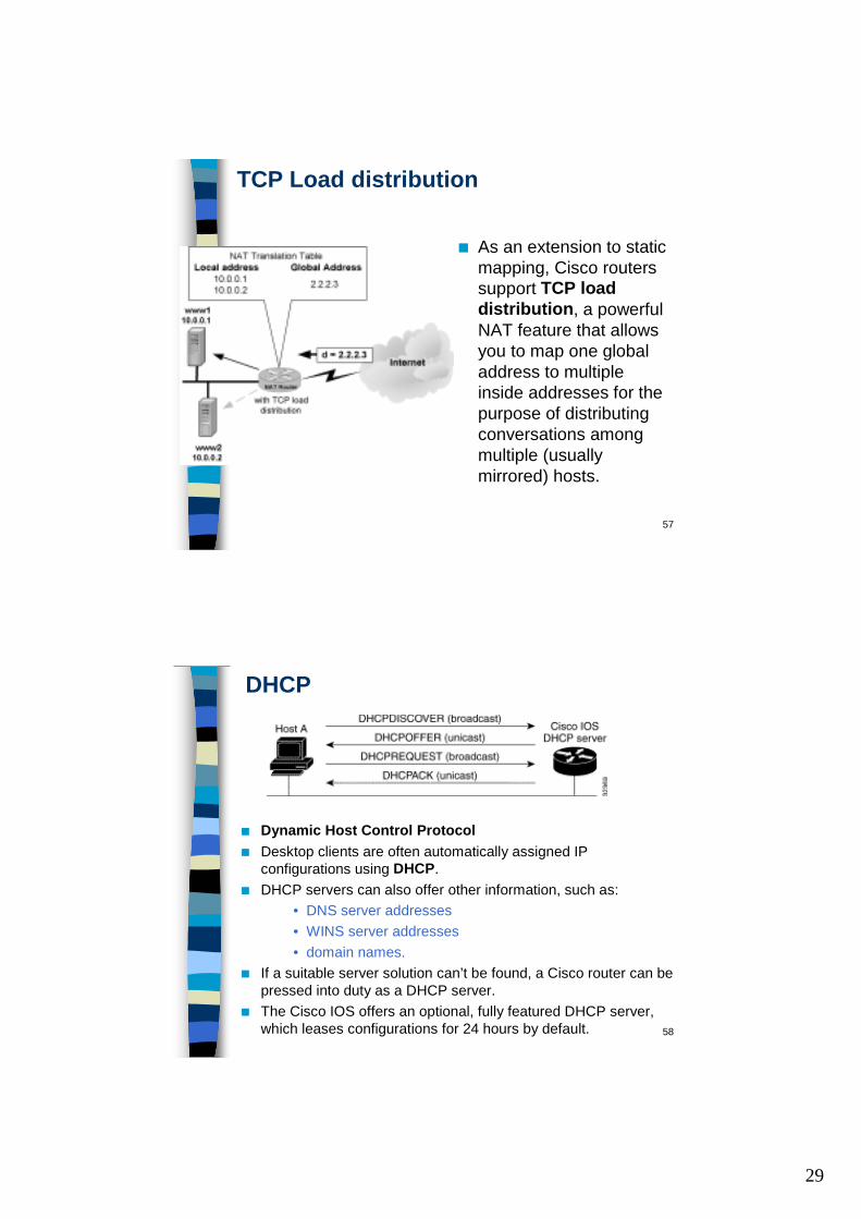
■ As an extension to static mapping, Cisco routers support TCP load distribution, a powerful NAT feature that allows you to map one global address to multiple inside addresses for the purpose of distributing conversations among multiple (usually mirrored) hosts.
58
DHCP
■ Dynamic Host Control Protocol■ Desktop clients are often automatically assigned IP
configurations using DHCP.■ DHCP servers can also offer other information, such as:
• DNS server addresses• WINS server addresses• domain names.
■ If a suitable server solution can’t be found, a Cisco router can be pressed into duty as a DHCP server.
■ The Cisco IOS offers an optional, fully featured DHCP server, which leases configurations for 24 hours by default.
30
59
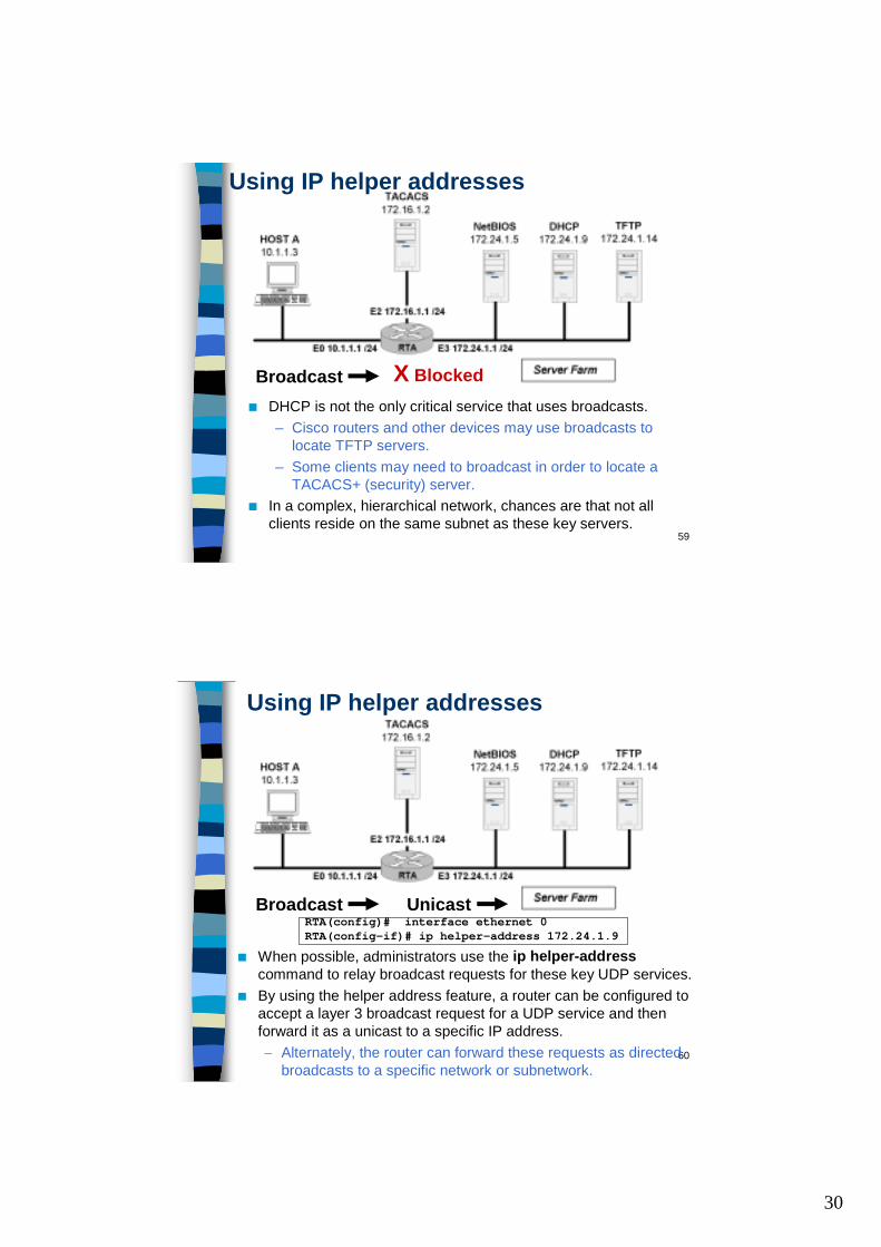
■ DHCP is not the only critical service that uses broadcasts. – Cisco routers and other devices may use broadcasts to
locate TFTP servers. – Some clients may need to broadcast in order to locate a
TACACS+ (security) server.■ In a complex, hierarchical network, chances are that not all
clients reside on the same subnet as these key servers.
Broadcast
Using IP helper addresses
X Blocked
60
■ When possible, administrators use the ip helper-addresscommand to relay broadcast requests for these key UDP services.
■ By using the helper address feature, a router can be configured to accept a layer 3 broadcast request for a UDP service and then forward it as a unicast to a specific IP address. – Alternately, the router can forward these requests as directed
broadcasts to a specific network or subnetwork.
Broadcast Unicast
Using IP helper addresses
RTA(config)# interface ethernet 0RTA(config-if)# ip helper-address 172.24.1.9
31
61
The 8 default servicesUDP Service UDP PortTime 37TACACS 49DNS 53BOOTP/DHCP 67BOOTP/DHCP 68Netbios Name 137Netbios Datagram 138TFTP 69
62
IP helper-addresses & IP forward-protocol
■ Q: What if you need to forward requests for a service not on this list?
■ A: The Cisco IOS provides the global configuration command, ip forward-protocol, to allow an administrator to forward any UDP port in addition to the default eight.RtrA(config)# ip forward-protocol udp 517
■ Same for removing protocols you do not want to forward.RtrA(config)# no ip forward-protocol udp 69
32
63
Using ip directed broadcast■ To enable the translation of directed broadcast (172.24.1.255) to
a layer 2 physical broadcast, use the ip directed-broadcastinterface configuration command. ip directed-broadcast [access-list-number]
■ AS for IP directed broadcast, my understanding is that you need to enable this feature if you have several servers on the same network and you are going to have multiple UDP services forwarded to that network.
■ For example, you have a NetBIOS server (172.24.1.5), a DHCP server (172.24.1.9), and a TFTP server (172.24.1.14).
■ You can either specify both addresses as helper addresses or specify 172.24.1.255 as a helper address on E0:RTA(config-if)# ip helper-address 172.24.1.255
■ If you turn on directed broadcast on E3, the latter method will work. (If you don't, it won't.)RTA(config-if)# ip directed-broadcast
64
Cabrillo College
Ch. 2 IP AddressingCCNP CCNP -- Advanced RoutingAdvanced Routing
Rick Graziani, Instructor