Embed Size (px)
Citation preview
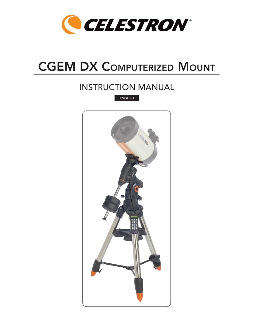
INSTRUCTION MANUAL
CGEM DX CoMputErizED Mount
ENGLISH
Table of ConTenTs
Introduction . . . . . . . . . . . . . . . . . . . . . . . . . . . . . . . . . . . . . 1
Warning . . . . . . . . . . . . . . . . . . . . . . . . . . . . . . . . . . . . . . 1
Assembly . . . . . . . . . . . . . . . . . . . . . . . . . . . . . . . . . . . . . . . 3
Setting up the Tripod . . . . . . . . . . . . . . . . . . . . . . . . . . . . 3
Attaching the Accessory Tray . . . . . . . . . . . . . . . . . . . . . 3
Attaching the Azimuth Adjustment Knobs . . . . . . . . . . . . 3
Attaching the Equatorial Mount . . . . . . . . . . . . . . . . . . . . 3
Installing the Counterweight Bar . . . . . . . . . . . . . . . . . . . 4
Installing the Counterweight . . . . . . . . . . . . . . . . . . . . . . 4
Attaching the Hand Control Holder . . . . . . . . . . . . . . . . 5
Attaching an Optical Tube to the Mount . . . . . . . . . . . . . 5
Moving the Telescope Manually . . . . . . . . . . . . . . . . . . . . 5
Balancing the Mount in R .A . . . . . . . . . . . . . . . . . . . . . . . . 5
Balancing the Mount in DEC . . . . . . . . . . . . . . . . . . . . . . . 6
Adjusting the Mount . . . . . . . . . . . . . . . . . . . . . . . . . . . . . 6
Adjusting the Mount in Altitude . . . . . . . . . . . . . . . . . 6
Adjusting the Mount in Azimuth . . . . . . . . . . . . . . . . . 6
Powering the Mount . . . . . . . . . . . . . . . . . . . . . . . . . . . . . 6
Hand Control . . . . . . . . . . . . . . . . . . . . . . . . . . . . . . . . . . . . 6
Hand Control Operation . . . . . . . . . . . . . . . . . . . . . . . 7
Alignment Procedures . . . . . . . . . . . . . . . . . . . . . . . . . . . 7
Startup Procedure . . . . . . . . . . . . . . . . . . . . . . . . . . . . . . . 8
Two Star Align . . . . . . . . . . . . . . . . . . . . . . . . . . . . . . . . . . 8
East/West (E/W) Filtering . . . . . . . . . . . . . . . . . . . . . . . 9
Quick-Align . . . . . . . . . . . . . . . . . . . . . . . . . . . . . . . . . . 10
Last Alignment . . . . . . . . . . . . . . . . . . . . . . . . . . . . . . . . 10
Re-Alignment . . . . . . . . . . . . . . . . . . . . . . . . . . . . . . . . . 10
Object Catalog . . . . . . . . . . . . . . . . . . . . . . . . . . . . . . . . 10
Selecting an Object . . . . . . . . . . . . . . . . . . . . . . . . . . 10
Slewing to an Object . . . . . . . . . . . . . . . . . . . . . . . . . 10
Finding Planets . . . . . . . . . . . . . . . . . . . . . . . . . . . . . 10
Tour Mode . . . . . . . . . . . . . . . . . . . . . . . . . . . . . . . . . .11
Constellation Tour . . . . . . . . . . . . . . . . . . . . . . . . . . . .11
Direction Buttons . . . . . . . . . . . . . . . . . . . . . . . . . . . . .11
Rate Button . . . . . . . . . . . . . . . . . . . . . . . . . . . . . . . . .11
Setup Procedures . . . . . . . . . . . . . . . . . . . . . . . . . . . . . . .11
Tracking Mode . . . . . . . . . . . . . . . . . . . . . . . . . . . . . . .11
Tracking Rate . . . . . . . . . . . . . . . . . . . . . . . . . . . . . . . .11
Date / Time . . . . . . . . . . . . . . . . . . . . . . . . . . . . . . . . . .11
User Defined Objects . . . . . . . . . . . . . . . . . . . . . . . . . .11
Get RA/DEC . . . . . . . . . . . . . . . . . . . . . . . . . . . . . . . 12
Goto R .A/ Dec . . . . . . . . . . . . . . . . . . . . . . . . . . . . . . 12
Identify . . . . . . . . . . . . . . . . . . . . . . . . . . . . . . . . . . . . 12
Precise GoTo . . . . . . . . . . . . . . . . . . . . . . . . . . . . . . . . . 12
Scope Setup Features . . . . . . . . . . . . . . . . . . . . . . . . . . 12
Setup Time-Site . . . . . . . . . . . . . . . . . . . . . . . . . . . . . 12
Anti-backlash . . . . . . . . . . . . . . . . . . . . . . . . . . . . . . . 12
Filter Limits . . . . . . . . . . . . . . . . . . . . . . . . . . . . . . . . 13
Direction Buttons . . . . . . . . . . . . . . . . . . . . . . . . . . . 13
Goto Approach . . . . . . . . . . . . . . . . . . . . . . . . . . . . . 13
Autoguide Rate . . . . . . . . . . . . . . . . . . . . . . . . . . . . . 13
OTA Orientation . . . . . . . . . . . . . . . . . . . . . . . . . . . . 14
Meridian . . . . . . . . . . . . . . . . . . . . . . . . . . . . . . . . . . . 14
Mount Settings . . . . . . . . . . . . . . . . . . . . . . . . . . . . . 14
RA Limits . . . . . . . . . . . . . . . . . . . . . . . . . . . . . . . . . . 14
Utility Features . . . . . . . . . . . . . . . . . . . . . . . . . . . . . . . . 15
Calibrate Mount . . . . . . . . . . . . . . . . . . . . . . . . . . . . 15
Home Position . . . . . . . . . . . . . . . . . . . . . . . . . . . . . . 15
Light Control . . . . . . . . . . . . . . . . . . . . . . . . . . . . . . . 15
Factory Settings . . . . . . . . . . . . . . . . . . . . . . . . . . . . 15
Version . . . . . . . . . . . . . . . . . . . . . . . . . . . . . . . . . . . . 15
Get Axis Position . . . . . . . . . . . . . . . . . . . . . . . . . . . . 15
Goto Axis Position . . . . . . . . . . . . . . . . . . . . . . . . . . . 15
Hibernate . . . . . . . . . . . . . . . . . . . . . . . . . . . . . . . . . . 15
Sun Menu . . . . . . . . . . . . . . . . . . . . . . . . . . . . . . . . . . 15
Scrolling Menu . . . . . . . . . . . . . . . . . . . . . . . . . . . . . . 15
Set Mount Position . . . . . . . . . . . . . . . . . . . . . . . . . . . . . 15
Turn On/Off GPS . . . . . . . . . . . . . . . . . . . . . . . . . . . . 15
Turn On/Off RTC . . . . . . . . . . . . . . . . . . . . . . . . . . . . 15
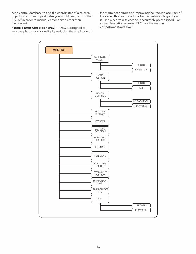
Periodic Error Correction (PEC) . . . . . . . . . . . . . . . . . 16
Astronomy Basics . . . . . . . . . . . . . . . . . . . . . . . . . . . . . . . 18
The Celestial Coordinate System . . . . . . . . . . . . . . . . . . 18
Motion of the Stars . . . . . . . . . . . . . . . . . . . . . . . . . . . . . 18
Polar Aligning the Mount . . . . . . . . . . . . . . . . . . . . . . . . 18
All-Star Polar Align . . . . . . . . . . . . . . . . . . . . . . . . . . . 19
Finding the North Celestial Pole . . . . . . . . . . . . . . . . . . 20
Optional Accessories . . . . . . . . . . . . . . . . . . . . . . . . . . . . 21
Appendix A – Technical Specifications . . . . . . . . . . . . . . 22
Appendix B - Glossary Of Terms . . . . . . . . . . . . . . . . . . . 22
Appendix C - RS-232 Connection . . . . . . . . . . . . . . . . . . 25
Appendix D – Maps Of Time Zones . . . . . . . . . . . . . . . . 27
Sky Maps . . . . . . . . . . . . . . . . . . . . . . . . . . . . . . . . . . . . . . 29
1
InTroduCTIon
Congratulations on your purchase of the Celestron CGEM DX Series Mount! The CGEM DX series continues in Celestron’s proud tradition combining large aperture optics with the sophistication and ease of use of our computerized GoTo mount .
If you are new to astronomy, you may wish to start off by using the built-in Sky Tour feature, which commands the mount to find the most interesting objects in the sky and automatically slews to each one . Or if you are an experienced amateur, you will appreciate the comprehensive database of over 40,000 objects, including customized lists of all the best deep-sky objects, bright double stars and variable stars . No matter your level of experience, the CGEM DX mount telescopes will unfold for you and your friends all the wonders of the Universe .
Some of the many standard features of the telescope include:
• Fullyenclosedopticalencodersforpositionlocation.
• Ergonomicallydesignedmountthatdisassemblesintocompact and portable pieces .
• Databasefilterlimitsforcreatingcustomobjectlists.
• Storageforprogrammableuserdefinedobjects; and many other high performance features!
Take time to read through this manual before embarking on your journey through the Universe . It may take a few observing sessions to become familiar with your mount, so you should keep this manual handy until you have fully mastered your telescope’s operation . The hand control has built-in instructions
to guide you through all the alignment procedures needed to have the telescope up and running in minutes . Use this manual in conjunction with the on-screen instructions provided by the hand control . The manual gives detailed information regarding each step as well as needed reference material and helpful hints guaranteed to make your observing experience as simple and pleasurable as possible .
The CGEM DX mount is designed to give you years of fun and rewarding observations . However, there are a few things to consider before using your telescope that will ensure your safety and protect your equipment .
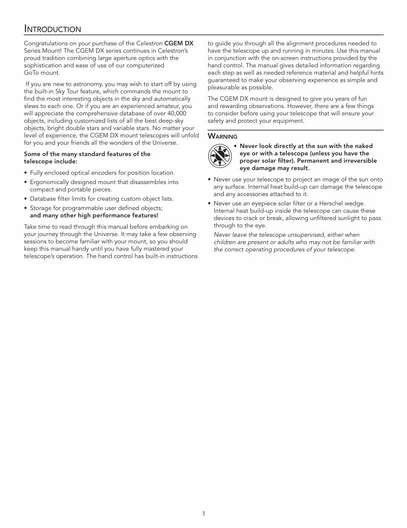
WarninG •Neverlookdirectlyatthesunwiththenakedeyeorwithatelescope(unlessyouhavethepropersolarfilter).Permanentandirreversibleeye damage may result.
• Neveruseyourtelescopetoprojectanimageofthesunontoany surface . Internal heat build-up can damage the telescope and any accessories attached to it .
• NeveruseaneyepiecesolarfilteroraHerschelwedge.Internal heat build-up inside the telescope can cause these devices to crack or break, allowing unfiltered sunlight to pass through to the eye .
Never leave the telescope unsupervised, either when children are present or adults who may not be familiar with the correct operating procedures of your telescope.
2
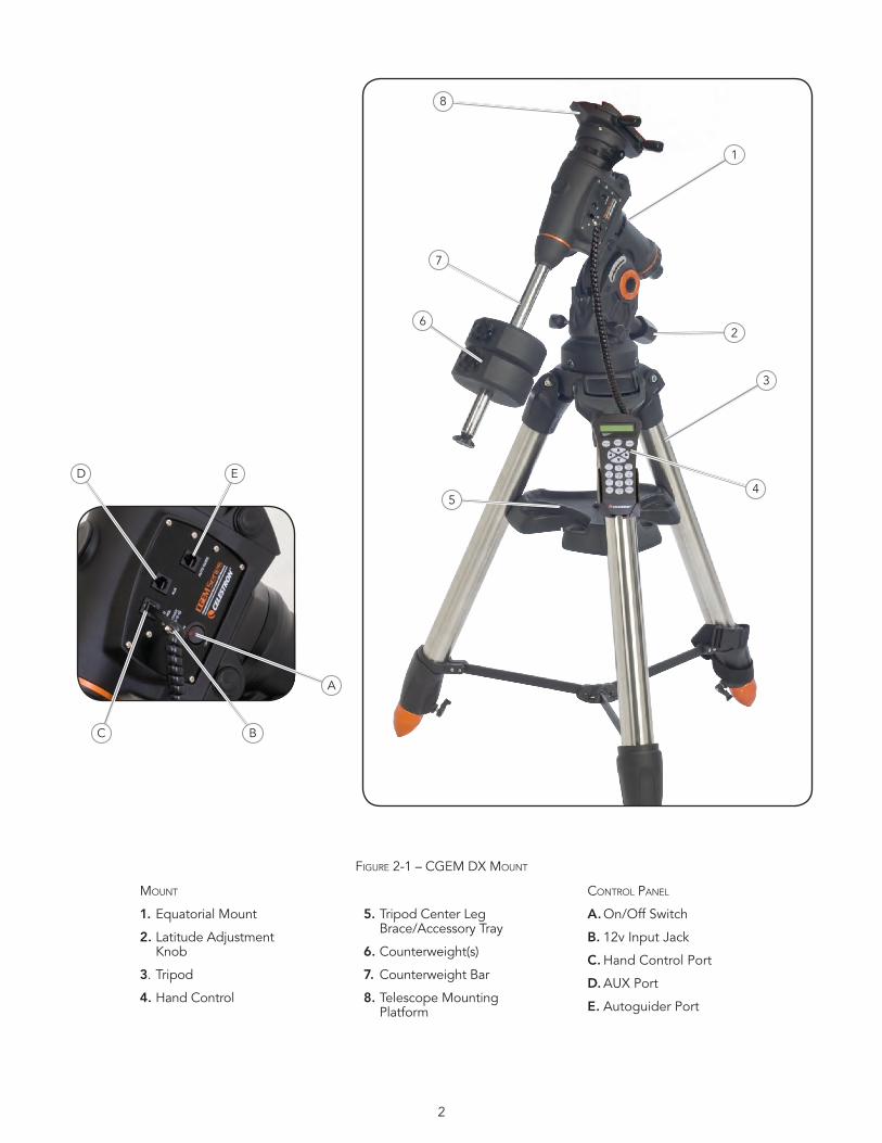
Figure 2-1 – CgeM DX Mount
Mount
1. Equatorial Mount
2. Latitude Adjustment Knob
3 . Tripod
4. Hand Control
5. Tripod Center Leg Brace/Accessory Tray
6. Counterweight(s)
7. Counterweight Bar
8. Telescope Mounting Platform
Control Panel
A. On/Off Switch
B. 12v Input Jack
C. Hand Control Port
D. AUX Port
E. Autoguider Port
1
2
3
45
6
7
8
A
BC
D E
3
assembly
The Celestron CGEM DX mount is shipped in three main boxes . In separate boxes are the following:
• EquatorialMountwithHandControl,CounterweightBar and tripod adapter plate included
• Tripod
• Counterweight(s)
Remove all the pieces from their respective boxes and place on a flat, clear work area . A large floor space is ideal . When setting up your Celestron mount you must start with the tripod and work up from there . These instructions are laid out in the order each task should be performed .
SEttinG up thE tripoD
The CGEM DX tripod comes with an all metal center leg brace / accessory tray to give rock solid support to the mount .
The tripod comes fully assembled with a metal plate, called the tripod head that holds the legs together at the top . In addition, there is a central rod that extends down from the tripod head that attaches the accessory tray between the legs . To set up the tripod:
1 . Stand the tripod upright and pull the tripod legs apart until each leg is fully extended . The tripod will now stand by itself . Once the tripod is set up, you can adjust the height at which it stands .
2 . Loosen the lever on the leg clamp so that the tripod leg can be adjusted .
3 . Slide the center portion of the tripod leg away from the tripod head until it is at the desired height .
4 . Tighten the levers on each leg clamp to hold the legs in place .
5 . Once that it is fully assembled, rotate the tripod so that one of the legs is pointing roughly towards north .
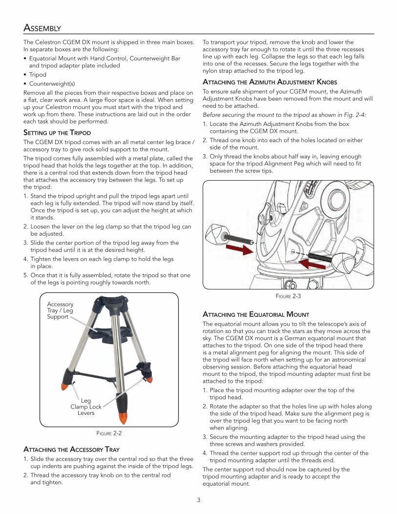
attaChinG thE aCCESSory tray 1 . Slide the accessory tray over the central rod so that the three
cup indents are pushing against the inside of the tripod legs .
2 . Thread the accessory tray knob on to the central rod and tighten .
To transport your tripod, remove the knob and lower the accessory tray far enough to rotate it until the three recesses line up with each leg . Collapse the legs so that each leg falls into one of the recesses . Secure the legs together with the nylon strap attached to the tripod leg .
attaChinG thE aziMuth aDjuStMEnt KnobS
To ensure safe shipment of your CGEM mount, the Azimuth Adjustment Knobs have been removed from the mount and will need to be attached .
Before securing the mount to the tripod as shown in Fig. 2-4:
1 . Locate the Azimuth Adjustment Knobs from the box containing the CGEM DX mount .
2 . Thread one knob into each of the holes located on either side of the mount .
3 . Only thread the knobs about half way in, leaving enough space for the tripod Alignment Peg which will need to fit between the screw tips .
attaChinG thE Equatorial Mount
The equatorial mount allows you to tilt the telescope’s axis of rotation so that you can track the stars as they move across the sky . The CGEM DX mount is a German equatorial mount that attaches to the tripod . On one side of the tripod head there is a metal alignment peg for aligning the mount . This side of the tripod will face north when setting up for an astronomical observing session . Before attaching the equatorial head mount to the tripod, the tripod mounting adapter must first be attached to the tripod:
1 . Place the tripod mounting adapter over the top of the tripod head .
2 . Rotate the adapter so that the holes line up with holes along the side of the tripod head . Make sure the alignment peg is over the tripod leg that you want to be facing north when aligning .
3 . Secure the mounting adapter to the tripod head using the three screws and washers provided .
4 . Thread the center support rod up through the center of the tripod mounting adapter until the threads end .
The center support rod should now be captured by the tripod mounting adapter and is ready to accept the equatorial mount .
Figure 2-3
Figure 2-2
Accessory Tray / Leg Support
Leg Clamp Lock
Levers
4
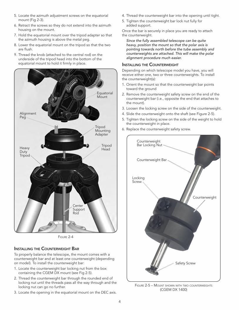
5 . Locate the azimuth adjustment screws on the equatorial mount (Fig 2-3) .
6 . Retract the screws so they do not extend into the azimuth housing on the mount .
7 . Hold the equatorial mount over the tripod adapter so that the azimuth housing is above the metal peg .
8 . Lower the equatorial mount on the tripod so that the two are flush .
9 . Thread the knob (attached to the central rod) on the underside of the tripod head into the bottom of the equatorial mount to hold it firmly in place .
inStallinG thE CountErWEiGht bar
To properly balance the telescope, the mount comes with a counterweight bar and at least one counterweight (depending on model) . To install the counterweight bar:
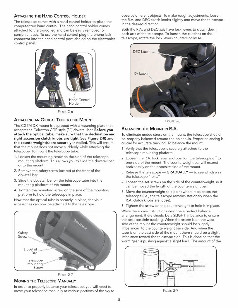
1 . Locate the counterweight bar locking nut from the box containing the CGEM DX mount (see Fig 2-5) .
2 . Thread the counterweight bar through the rounded end of locking nut until the threads pass all the way through and the locking nut can go no further .
3 . Locate the opening in the equatorial mount on the DEC axis .
4 . Thread the counterweight bar into the opening until tight .
5 . Tighten the counterweight bar lock nut fully for added support .
Once the bar is securely in place you are ready to attach the counterweight .
Since the fully assembled telescope can be quite heavy, position the mount so that the polar axis is pointing towards north before the tube assembly and counterweights are attached. This will make the polar alignment procedure much easier.
inStallinG thE CountErWEiGht
Depending on which telescope model you have, you will receive either one, two or three counterweights . To install the counterweight(s):
1 . Orient the mount so that the counterweight bar points toward the ground
2 . Remove the counterweight safety screw on the end of the counterweight bar (i .e ., opposite the end that attaches to the mount) .
3 . Loosen the locking screw on the side of the counterweight .
4 . Slide the counterweight onto the shaft (see Figure 2-5) .
5 . Tighten the locking screw on the side of the weight to hold the counterweight in place .
6 . Replace the counterweight safety screw .
Figure 2-4
Equatorial Mount
Alignment Peg
Tripod Mounting Adapter
Heavy Duty Tripod
Center Support Rod
Tripod Head
Figure 2-5 – Mount shown with two Counterweights (CgeM DX 1400)
Counterweight Bar Locking Nut
Counterweight Bar
Locking Screw
Counterweight
Safety Screw
5
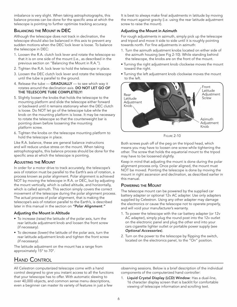
attaChinG thE hanD Control holDEr The telescope comes with a hand control holder to place the computerized hand control . The hand control holder comes attached to the tripod leg and can be easily removed for convenient use . To use the hand control plug the phone jack connector into the hand control port labeled on the electronics control panel .
attaChinG an optiCal tubE to thE Mount
The CGEM DX mount is equipped with a mounting plate that accepts the Celestron CGE style (3”) dovetail bar . Before you attach the optical tube, make sure that the declination and rightascensionclutchknobsaretight(seeFigure2-8)andthecounterweight(s)aresecurelyinstalled. This will ensure that the mount does not move suddenly while attaching the telescope . To mount the telescope tube:
1 . Loosen the mounting screw on the side of the telescope mounting platform . This allows you to slide the dovetail bar onto the mount .
2 . Remove the safety screw located at the front of the dovetail bar .
3 . Slide the dovetail bar on the telescope tube into the mounting platform of the mount .
4 . Tighten the mounting screw on the side of the mounting platform to hold the telescope in place .
Now that the optical tube is securely in place, the visual accessories can now be attached to the telescope .
MovinG thE tElESCopE Manually
In order to properly balance your telescope, you will need to move your telescope manually at various portions of the sky to
observe different objects . To make rough adjustments, loosen the R .A . and DEC clutch knobs slightly and move the telescope in the desired direction .
Both the R .A . and DEC axis have lock levers to clutch down each axis of the telescope . To loosen the clutches on the telescope, rotate the lock levers counterclockwise .
balanCinG thE Mount in r.a.To eliminate undue stress on the mount, the telescope should be properly balanced around the polar axis . Proper balancing is crucial for accurate tracking . To balance the mount:
1 . Verify that the telescope is securely attached to the telescope mounting platform .
2 . Loosen the R .A . lock lever and position the telescope off to one side of the mount . The counterweight bar will extend horizontally on the opposite side of the mount .
3 . Release the telescope — GRADUALLY — to see which way the telescope “rolls .”
4 . Loosen the set screws on the side of the counterweight so it can be moved the length of the counterweight bar .
5 . Move the counterweight to a point where it balances the telescope (i .e ., the telescope remains stationary when the R .A . clutch knobs are loose) .
6 . Tighten the screw on the counterweight to hold it in place .
While the above instructions describe a perfect balance arrangement, there should be a SLIGHT imbalance to ensure the best possible tracking . When the scope is on the west side of the mount the counterweight should be slightly imbalanced to the counterweight bar side . And when the tube is on the east side of the mount there should be a slight imbalance toward the telescope side . This is done so that the worm gear is pushing against a slight load . The amount of the
Figure 2-7
Safety Screw
Dovetail Bar
Telescope Mounting
Screw
Figure 2-8
DEC Lock
RA Lock
Figure 2-9
Figure 2-6
Hand Control Holder
6
imbalance is very slight . When taking astrophotographs, this balance process can be done for the specific area at which the telescope is pointing to further optimize tracking accuracy .
balanCinG thE Mount in DECAlthough the telescope does not track in declination, the telescope should also be balanced in this axis to prevent any sudden motions when the DEC lock lever is loose . To balance the telescope in DEC:
1 . Loosen the R .A . clutch lock lever and rotate the telescope so that it is on one side of the mount (i .e ., as described in the previous section on “Balancing the Mount in R .A .”) .
2 . Tighten the R .A . lock lever to hold the telescope in place .
3 . Loosen the DEC clutch lock lever and rotate the telescope until the tube is parallel to the ground .
4 . Release the tube — GRADUALLY — to see which way it rotates around the declination axis . DONOTLETGOOFTHE TELESCOPE TUBE COMPLETELY!
5 . Slightly loosen the knobs that holds the telescope to the mounting platform and slide the telescope either forward or backward until it remains stationary when the DEC clutch is loose . Do NOT let go of the telescope tube while the knob on the mounting platform is loose . It may be necessary to rotate the telescope so that the counterweight bar is pointing down before loosening the mounting platform screw .
6 . Tighten the knobs on the telescope mounting platform to hold the telescope in place .
Like R .A . balance, these are general balance instructions and will reduce undue stress on the mount . When taking astrophotographs, this balance process should be done for the specific area at which the telescope is pointing .
aDjuStinG thE Mount
In order for a motor drive to track accurately, the telescope’s axis of rotation must be parallel to the Earth’s axis of rotation, a process known as polar alignment . Polar alignment is achieved NOT by moving the telescope in R .A . or DEC, but by adjusting the mount vertically, which is called altitude, and horizontally, which is called azimuth . This section simply covers the correct movement of the telescope during the polar alignment process . The actual process of polar alignment, that is making the telescope’s axis of rotation parallel to the Earth’s, is described later in this manual in the section on “Polar Alignment .”
Adjusting the Mount in Altitude• Toincrease(raise) the latitude of the polar axis, turn the
rear latitude adjustment knob and loosen the front screw (if necessary) .
• Todecrease(lower) the latitude of the polar axis, turn the rear latitude adjustment knob and tighten the front screw (if necessary) .
The latitude adjustment on the mount has a range from approximately 15° to 70° .
It is best to always make final adjustments in latitude by moving the mount against gravity (i .e . using the rear latitude adjustment screw to raise the mount) .
Adjusting the Mount in AzimuthFor rough adjustments in azimuth, simply pick up the telescope and tripod and move it side to side until it is roughly pointing towards north . For fine adjustments in azimuth:
1 . Turn the azimuth adjustment knobs located on either side of the azimuth housing (see Fig 2-10) . While standing behind the telescope, the knobs are on the front of the mount .
•Turningtherightadjustmentknobclockwisemovesthemounttoward the right .
•Turningtheleftadjustmentknobclockwisemovesthemountto the left .
Both screws push off of the peg on the tripod head, which means you may have to loosen one screw while tightening the other . The screw that holds the equatorial mount to the tripod may have to be loosened slightly .
Keep in mind that adjusting the mount is done during the polar alignment process only . Once polar aligned, the mount must NOT be moved . Pointing the telescope is done by moving the mount in right ascension and declination, as described earlier in this manual .
poWErinG thE Mount
The telescope mount can be powered by the supplied car battery adapter or optional 12v AC adapter . Use only adapters supplied by Celestron . Using any other adapter may damage the electronics or cause the telescope not to operate properly, and will void your manufacturer’s warranty .
1 . To power the telescope with the car battery adapter (or 12v AC adapter), simply plug the round post into the 12v outlet on the electronic panel and plug the other end into your cars cigarette lighter outlet or portable power supply (see Optional Accessories) .
2 . Turn on the power to the telescope by flipping the switch, located on the electronics panel, to the “On” position .
Hand ConTrol
All Celestron computerized telescope come with a hand control designed to give you instant access to all the functions that your telescope has to offer . With automatic slewing to over 40,000 objects, and common sense menu descriptions, even a beginner can master its variety of features in just a few
observing sessions . Below is a brief description of the individual components of the computerized hand controller:
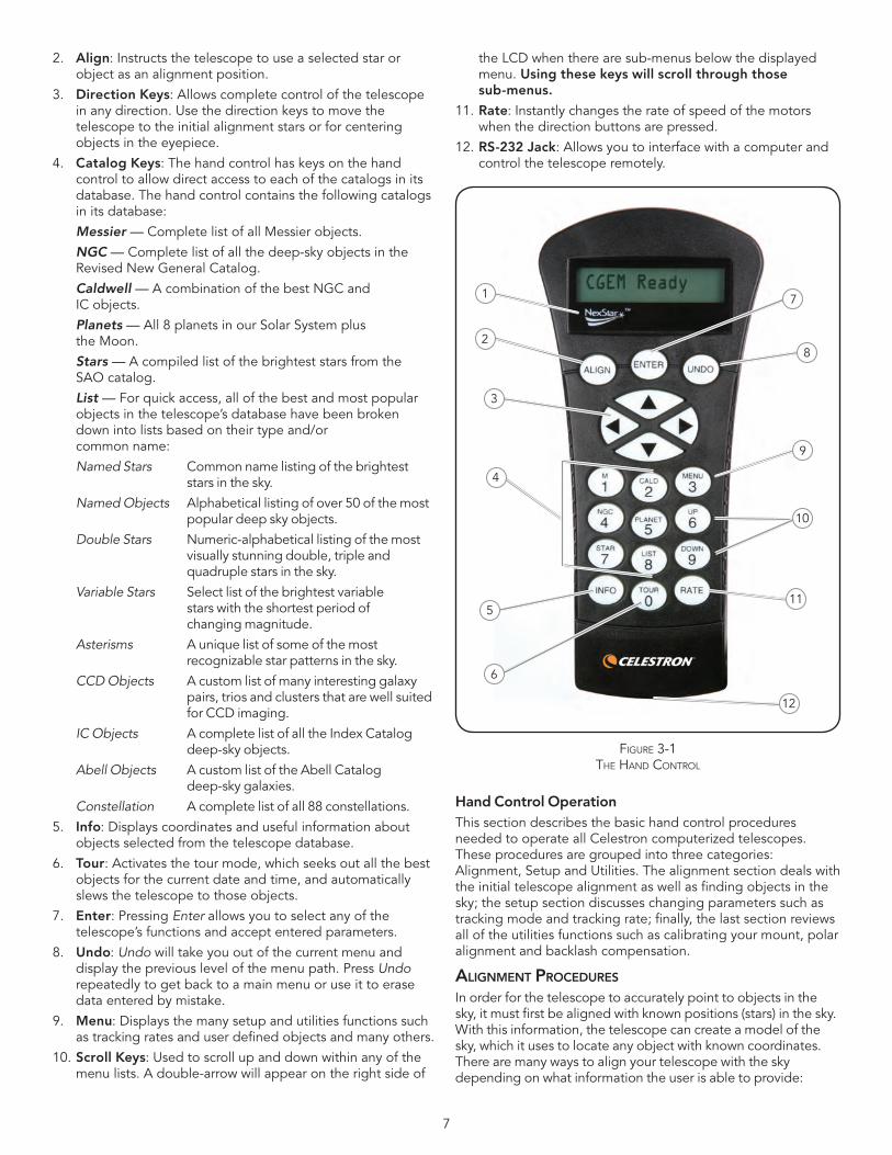
1 . LiquidCrystalDisplay(LCD)Window: Has a dual-line, 16 character display screen that is backlit for comfortable viewing of telescope information and scrolling text .
Figure 2-10
Rear Latitude Adjustment Knob
Front Latitude Adjustment Screw
Azimuth Adjustment Knob
7
2 . Align: Instructs the telescope to use a selected star or object as an alignment position .
3 . Direction Keys: Allows complete control of the telescope in any direction . Use the direction keys to move the telescope to the initial alignment stars or for centering objects in the eyepiece .
4 . Catalog Keys: The hand control has keys on the hand control to allow direct access to each of the catalogs in its database . The hand control contains the following catalogs in its database:
Messier — Complete list of all Messier objects .
NGC — Complete list of all the deep-sky objects in the Revised New General Catalog .
Caldwell — A combination of the best NGC and IC objects .
Planets — All 8 planets in our Solar System plus the Moon .
Stars — A compiled list of the brightest stars from the SAO catalog .
List — For quick access, all of the best and most popular objects in the telescope’s database have been broken down into lists based on their type and/or common name:
Named Stars Common name listing of the brightest stars in the sky .
Named Objects Alphabetical listing of over 50 of the most popular deep sky objects .
Double Stars Numeric-alphabetical listing of the most visually stunning double, triple and quadruple stars in the sky .
Variable Stars Select list of the brightest variable stars with the shortest period of changing magnitude .
Asterisms A unique list of some of the most recognizable star patterns in the sky .
CCD Objects A custom list of many interesting galaxy pairs, trios and clusters that are well suited for CCD imaging .
IC Objects A complete list of all the Index Catalog deep-sky objects .
Abell Objects A custom list of the Abell Catalog deep-sky galaxies .
Constellation A complete list of all 88 constellations .
5 . Info: Displays coordinates and useful information about objects selected from the telescope database .
6 . Tour: Activates the tour mode, which seeks out all the best objects for the current date and time, and automatically slews the telescope to those objects .
7 . Enter: Pressing Enter allows you to select any of the telescope’s functions and accept entered parameters .
8 . Undo: Undo will take you out of the current menu and display the previous level of the menu path . Press Undo repeatedly to get back to a main menu or use it to erase data entered by mistake .
9 . Menu: Displays the many setup and utilities functions such as tracking rates and user defined objects and many others .
10 . Scroll Keys: Used to scroll up and down within any of the menu lists . A double-arrow will appear on the right side of
the LCD when there are sub-menus below the displayed menu .Usingthesekeyswillscrollthroughthose sub-menus.
11 . Rate: Instantly changes the rate of speed of the motors when the direction buttons are pressed .
12 . RS-232 Jack: Allows you to interface with a computer and control the telescope remotely .
Hand Control OperationThis section describes the basic hand control procedures needed to operate all Celestron computerized telescopes . These procedures are grouped into three categories: Alignment, Setup and Utilities . The alignment section deals with the initial telescope alignment as well as finding objects in the sky;thesetupsectiondiscusseschangingparameterssuchastrackingmodeandtrackingrate;finally,thelastsectionreviewsall of the utilities functions such as calibrating your mount, polar alignment and backlash compensation .
aliGnMEnt proCEDurES
In order for the telescope to accurately point to objects in the sky, it must first be aligned with known positions (stars) in the sky . With this information, the telescope can create a model of the sky, which it uses to locate any object with known coordinates . There are many ways to align your telescope with the sky depending on what information the user is able to provide:
Figure 3-1the hanD Control
1
2
3
4
6
511
10
9
8
7
12
8
TwoStarAlign uses the entered time/location information and allows the user to select which two alignment stars the telescope will automatically slew to . One Star Align uses the same time/location information but only uses one star for alignment . Solar System Align will display a list of visible daytime objects (planets and the moon) available to align the telescope . Quick-Align will ask you to input all the same information as you would for the Auto Align procedure . However, instead of slewing to the alignment stars for centering and alignment, the telescope bypasses this step and simply models the sky based on the information given . Finally, Last Alignment restores your last saved star alignment and switch position . Last Alignment also serves as a good safeguard in case the telescope should lose power .
Startup proCEDurE
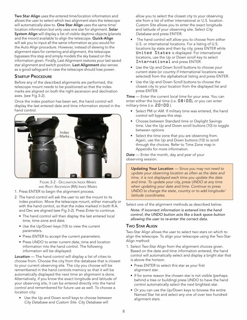
Before any of the described alignments are performed, the telescope mount needs to be positioned so that the index marks are aligned on both the right ascension and declination axes . (see Fig 3-2) .
Once the index position has been set, the hand control will display the last entered date and time information stored in the hand control .
1 . Press ENTER to begin the alignment process .
2 . The hand control will ask the user to set the mount to its index position . Move the telescope mount, either manually or with the hand control, so that the index marked in both R .A . and Dec are aligned (see Fig 3-2) . Press Enter to continue .
• Thehandcontrolwillthendisplaythelastenteredlocaltime, time zone and date .
• UsetheUp/Downkeys(10)toviewthecurrentparameters .
• PressENTERtoacceptthecurrentparameters.
• PressUNDOtoentercurrentdate,timeandlocationinformation into the hand control . The following information will be displayed:
Location — The hand control will display a list of cities to choose from . Choose the city from the database that is closest to your current observing site . The city you choose will be remembered in the hand controls memory so that it will be automatically displayed the next time an alignment is done . Alternatively, if you know the exact longitude and latitude of your observing site, it can be entered directly into the hand control and remembered for future use as well . To choose a location city:
• UsetheUpandDownscrollkeystochoosebetweenCity Database and Custom Site . City Database will
allow you to select the closest city to your observing site from a list of either international or U .S . location . Custom Site allows you to enter the exact longitude and latitude of your observing site . Select City Database and press ENTER .
• ThehandcontrolwillallowyoutochoosefromeitherU .S . or international locations . For a listing of U .S . locations by state and then by city, press ENTER while United States is displayed . For international locations, use the Up or Down scroll key to select International and press ENTER .
• UsetheUpandDownScrollbuttonstochooseyourcurrent state (or country if International locations was selected) from the alphabetical listing and press ENTER .
• UsetheUpandDownScrollbuttonstochoosetheclosest city to your location from the displayed list and press ENTER .
Time — Enter the current local time for your area . You can enter either the local time (i .e . 08:00), or you can enter military time (i .e . 20:00 ) .
• SelectPMorAM.Ifmilitarytimewasentered,thehandcontrol will bypass this step .
• ChoosebetweenStandardtimeorDaylightSavingstime . Use the Up and Down scroll buttons (10) to toggle between options .
• Selectthetimezonethatyouareobservingfrom.Again, use the Up and Down buttons (10) to scroll through the choices . Refer to Time Zone map in Appendix for more information .
Date — Enter the month, day and year of your observing session .
Updating Your Location — Since you may not need to update your observing location as often as the date and time, it is not displayed each time you update the date and time. To update your city, press UNDO at any time when updating your date and time. Continue to press UNDO to change the state, country or to add longitude/latitude coordinates.
Select one of the alignment methods as described below .
Note: If incorrect information is entered into the hand control, the UNDO button acts like a back space button allowing the user to re-enter the correct data.
tWo Star aliGn
Two-Star Align allows the user to select two stars on which to align the telescope . To align your telescope using the Two-Star Align method:
1 . Select Two-Star Align from the alignment choices given . Based on the date and time information entered, the hand control will automatically select and display a bright star that is above the horizon .
• PressENTERtoselectthisstarasyourfirst alignment star .
• Ifforsomereasonthechosenstarisnotvisible(perhapsbehind a tree or building) press UNDO to have the hand control automatically select the next brightest star .
• OryoucanusetheUp/DownkeystobrowsetheentireNamed Star list and select any one of over two hundred alignment stars .
Figure 3-2 - DeClination inDeX Marks anD right asCension (ra) inDeX Marks
Index Marks
9
2 . Once the telescope is finished slewing to your first alignment star, the display will ask you to use the arrow buttons to align the selected star with the cross hairs in the center of the finderscope . When centered in the finder, press ENTER .
3 . The display will then instruct you to center the star in the field of view of the eyepiece . When the star is centered, press ALIGN to accept this star as your first alignment star .
4 . After the first alignment star has been entered the hand control will automatically select a second alignment star and have you repeat this procedure for that star .
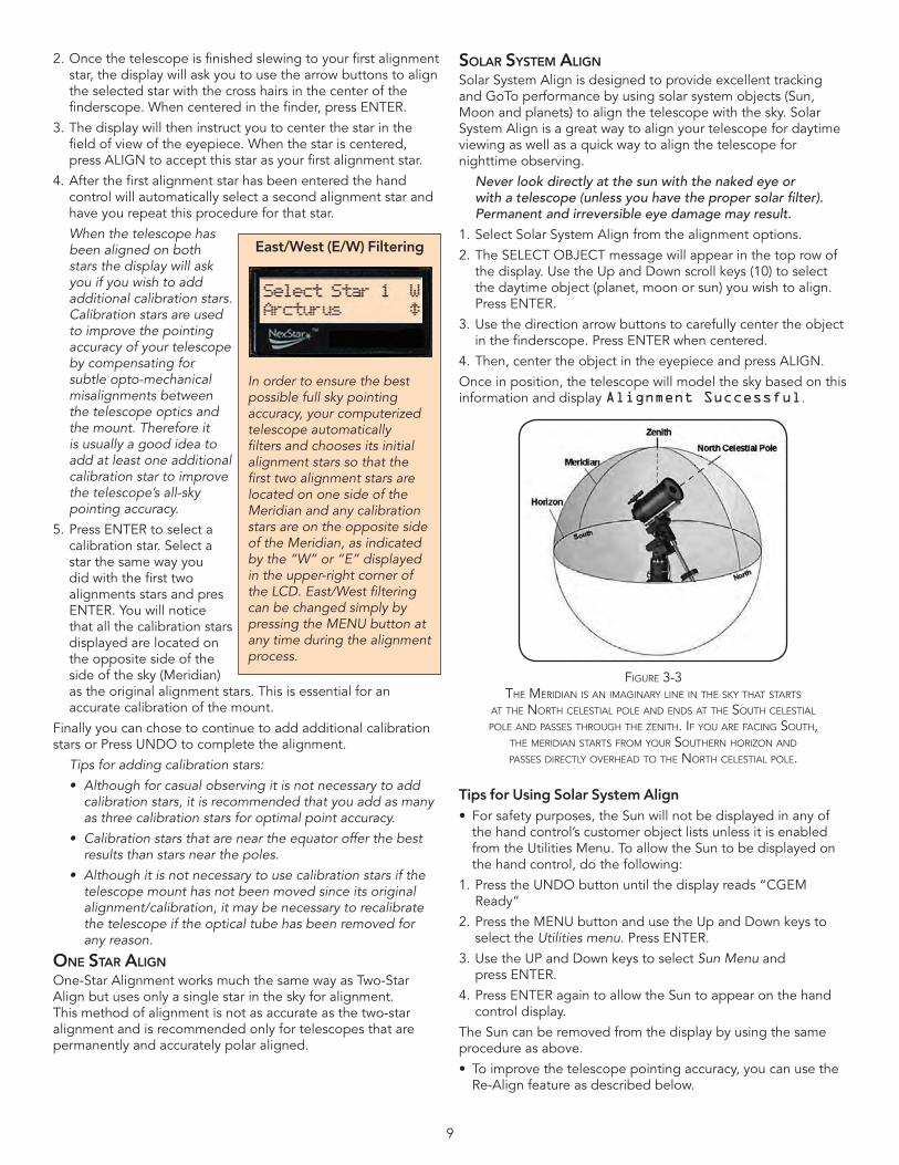
When the telescope has been aligned on both stars the display will ask you if you wish to add additional calibration stars. Calibration stars are used to improve the pointing accuracy of your telescope by compensating for subtle opto-mechanical misalignments between the telescope optics and the mount. Therefore it is usually a good idea to add at least one additional calibration star to improve the telescope’s all-sky pointing accuracy.
5 . Press ENTER to select a calibration star . Select a star the same way you did with the first two alignments stars and pres ENTER . You will notice that all the calibration stars displayed are located on the opposite side of the side of the sky (Meridian) as the original alignment stars . This is essential for an accurate calibration of the mount .
Finally you can chose to continue to add additional calibration stars or Press UNDO to complete the alignment .
Tips for adding calibration stars:
• Althoughforcasualobservingitisnotnecessarytoaddcalibration stars, it is recommended that you add as many as three calibration stars for optimal point accuracy.
• Calibrationstarsthatareneartheequatorofferthebestresults than stars near the poles.
• Althoughitisnotnecessarytousecalibrationstarsifthetelescope mount has not been moved since its original alignment/calibration, it may be necessary to recalibrate the telescope if the optical tube has been removed for any reason.
onE Star aliGn
One-Star Alignment works much the same way as Two-Star Align but uses only a single star in the sky for alignment . This method of alignment is not as accurate as the two-star alignment and is recommended only for telescopes that are permanently and accurately polar aligned .
Solar SyStEM aliGn
Solar System Align is designed to provide excellent tracking and GoTo performance by using solar system objects (Sun, Moon and planets) to align the telescope with the sky . Solar System Align is a great way to align your telescope for daytime viewing as well as a quick way to align the telescope for nighttime observing .
Never look directly at the sun with the naked eye or with a telescope (unless you have the proper solar filter). Permanent and irreversible eye damage may result.
1 . Select Solar System Align from the alignment options .
2 . The SELECT OBJECT message will appear in the top row of the display . Use the Up and Down scroll keys (10) to select the daytime object (planet, moon or sun) you wish to align . Press ENTER .
3 . Use the direction arrow buttons to carefully center the object in the finderscope . Press ENTER when centered .
4 . Then, center the object in the eyepiece and press ALIGN .
Once in position, the telescope will model the sky based on this information and display Alignment Successful .
Tips for Using Solar System Align• Forsafetypurposes,theSunwillnotbedisplayedinanyof
the hand control’s customer object lists unless it is enabled from the Utilities Menu . To allow the Sun to be displayed on the hand control, do the following:
1 . Press the UNDO button until the display reads “CGEM Ready”
2 . Press the MENU button and use the Up and Down keys to select the Utilities menu . Press ENTER .
3 . Use the UP and Down keys to select Sun Menu and press ENTER .
4 . Press ENTER again to allow the Sun to appear on the hand control display .
The Sun can be removed from the display by using the same procedure as above .
• Toimprovethetelescopepointingaccuracy,youcanusetheRe-Align feature as described below .
East/West(E/W)Filtering
In order to ensure the best possible full sky pointing accuracy, your computerized telescope automatically filters and chooses its initial alignment stars so that the first two alignment stars are located on one side of the Meridian and any calibration stars are on the opposite side of the Meridian, as indicated by the “W” or “E” displayed in the upper-right corner of the LCD. East/West filtering can be changed simply by pressing the MENU button at any time during the alignment process.
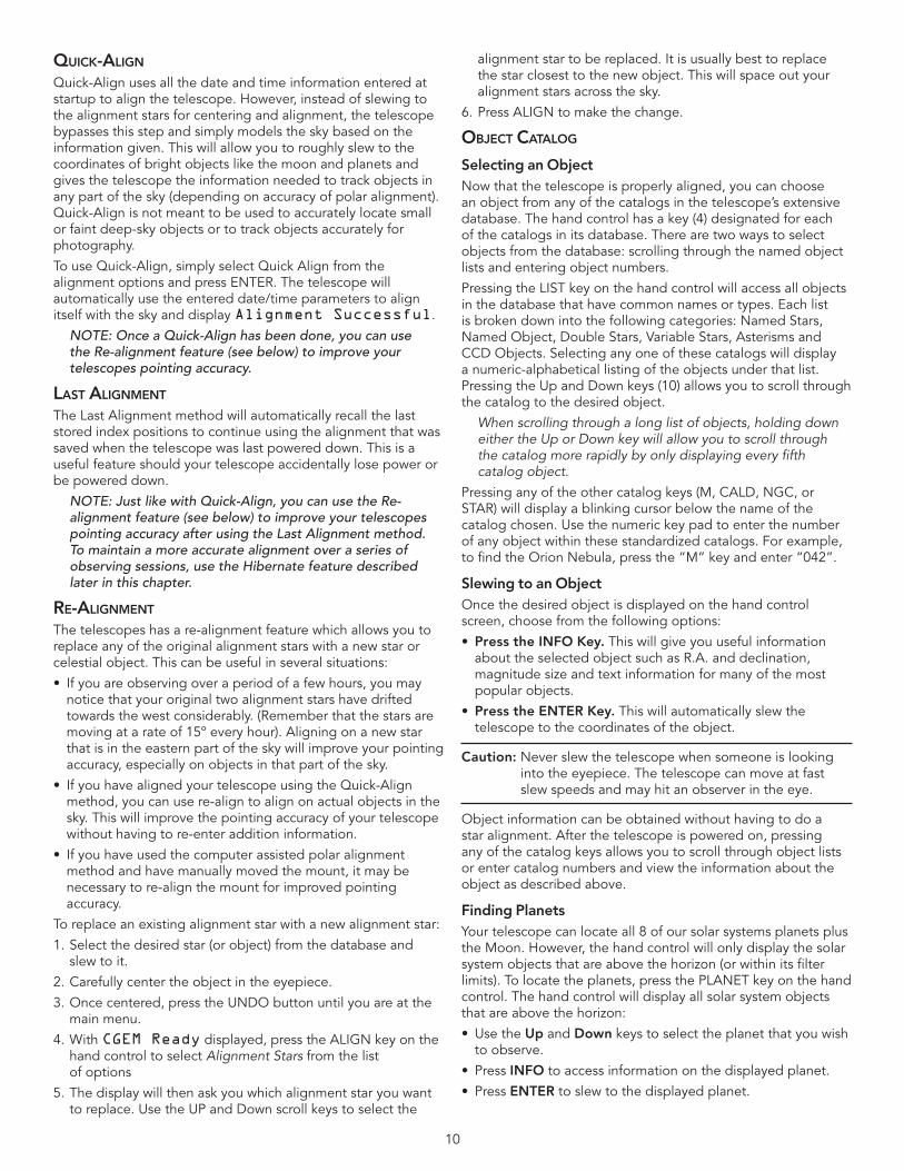
Figure 3-3the MeriDian is an iMaginary line in the sky that starts
at the north Celestial Pole anD enDs at the south Celestial Pole anD Passes through the zenith. iF you are FaCing south,
the MeriDian starts FroM your southern horizon anD Passes DireCtly overheaD to the north Celestial Pole.
10
quiCK-aliGn Quick-Align uses all the date and time information entered at startup to align the telescope . However, instead of slewing to the alignment stars for centering and alignment, the telescope bypasses this step and simply models the sky based on the information given . This will allow you to roughly slew to the coordinates of bright objects like the moon and planets and gives the telescope the information needed to track objects in any part of the sky (depending on accuracy of polar alignment) . Quick-Align is not meant to be used to accurately locate small or faint deep-sky objects or to track objects accurately for photography .
To use Quick-Align, simply select Quick Align from the alignment options and press ENTER . The telescope will automatically use the entered date/time parameters to align itself with the sky and display Alignment Successful .
NOTE: Once a Quick-Align has been done, you can use the Re-alignment feature (see below) to improve your telescopes pointing accuracy.
laSt aliGnMEnt
The Last Alignment method will automatically recall the last stored index positions to continue using the alignment that was saved when the telescope was last powered down . This is a useful feature should your telescope accidentally lose power or be powered down .
NOTE: Just like with Quick-Align, you can use the Re-alignment feature (see below) to improve your telescopes pointing accuracy after using the Last Alignment method. To maintain a more accurate alignment over a series of observing sessions, use the Hibernate feature described later in this chapter.
rE-aliGnMEnt
The telescopes has a re-alignment feature which allows you to replace any of the original alignment stars with a new star or celestial object . This can be useful in several situations:
• Ifyouareobservingoveraperiodofafewhours,youmaynotice that your original two alignment stars have drifted towards the west considerably . (Remember that the stars are moving at a rate of 15º every hour) . Aligning on a new star that is in the eastern part of the sky will improve your pointing accuracy, especially on objects in that part of the sky .
• IfyouhavealignedyourtelescopeusingtheQuick-Alignmethod, you can use re-align to align on actual objects in the sky . This will improve the pointing accuracy of your telescope without having to re-enter addition information .
• Ifyouhaveusedthecomputerassistedpolaralignmentmethod and have manually moved the mount, it may be necessary to re-align the mount for improved pointing accuracy .
To replace an existing alignment star with a new alignment star:
1 . Select the desired star (or object) from the database and slew to it .
2 . Carefully center the object in the eyepiece .
3 . Once centered, press the UNDO button until you are at the main menu .
4 . With CGEM Ready displayed, press the ALIGN key on the hand control to select Alignment Stars from the list of options
5 . The display will then ask you which alignment star you want to replace . Use the UP and Down scroll keys to select the
alignment star to be replaced . It is usually best to replace the star closest to the new object . This will space out your alignment stars across the sky .
6 . Press ALIGN to make the change .
objECt CataloG
Selecting an ObjectNow that the telescope is properly aligned, you can choose an object from any of the catalogs in the telescope’s extensive database . The hand control has a key (4) designated for each of the catalogs in its database . There are two ways to select objects from the database: scrolling through the named object lists and entering object numbers .
Pressing the LIST key on the hand control will access all objects in the database that have common names or types . Each list is broken down into the following categories: Named Stars, Named Object, Double Stars, Variable Stars, Asterisms and CCD Objects . Selecting any one of these catalogs will display a numeric-alphabetical listing of the objects under that list . Pressing the Up and Down keys (10) allows you to scroll through the catalog to the desired object .
When scrolling through a long list of objects, holding down either the Up or Down key will allow you to scroll through the catalog more rapidly by only displaying every fifth catalog object.
Pressing any of the other catalog keys (M, CALD, NGC, or STAR) will display a blinking cursor below the name of the catalog chosen . Use the numeric key pad to enter the number of any object within these standardized catalogs . For example, to find the Orion Nebula, press the “M” key and enter “042” .
SlewingtoanObjectOnce the desired object is displayed on the hand control screen, choose from the following options:
• PresstheINFOKey. This will give you useful information about the selected object such as R .A . and declination, magnitude size and text information for many of the most popular objects .
• Press the ENTER Key. This will automatically slew the telescope to the coordinates of the object .
Caution: Never slew the telescope when someone is looking into the eyepiece . The telescope can move at fast slew speeds and may hit an observer in the eye .
Object information can be obtained without having to do a star alignment . After the telescope is powered on, pressing any of the catalog keys allows you to scroll through object lists or enter catalog numbers and view the information about the object as described above .
FindingPlanetsYour telescope can locate all 8 of our solar systems planets plus the Moon . However, the hand control will only display the solar system objects that are above the horizon (or within its filter limits) . To locate the planets, press the PLANET key on the hand control . The hand control will display all solar system objects that are above the horizon:
• UsetheUp and Down keys to select the planet that you wish to observe .
• PressINFO to access information on the displayed planet .
• PressENTER to slew to the displayed planet .
11
Tour ModeThe telescopes include a tour feature which automatically allows the user to choose from a list of interesting objects based on the date and time in which you are observing . The automatic tour will display only those objects that are within your set filter limits (see Filter Limits in the Setup Procedures section of the manual) . To activate the Tour mode, press the TOUR key (6) on the hand control . The hand control will display the best objects to observe that are currently in the sky .
• Toseeinformationanddataaboutthedisplayedobject,press the INFO key .
• Toslewtotheobjectdisplayed,pressENTER.
• Toseethenexttourobject,presstheUpkey.
Constellation TourIn addition to the Tour Mode, your telescope has a Constellation Tour that allows the user to take a tour of all the best objects in each of the 88 constellations . Selecting Constellation from the LIST menu will display all the constellation names that are above the user defined horizon (filter limits) . Once a constellation is selected, you can choose from any of the database object catalogs to produce a list of all the available objects in that constellation .
• Toseeinformationanddataaboutthedisplayedobject,press the INFO key .
• Toslewtotheobjectdisplayed,pressENTER.
• Toseethenexttourobject,presstheUpkey.
Direction ButtonsThe hand control has four direction buttons (3) in the center of the hand control which control the telescope’s motion in altitude (up and down) and azimuth (left and right) . The telescope can be controlled at nine different speed rates .
Rate Button
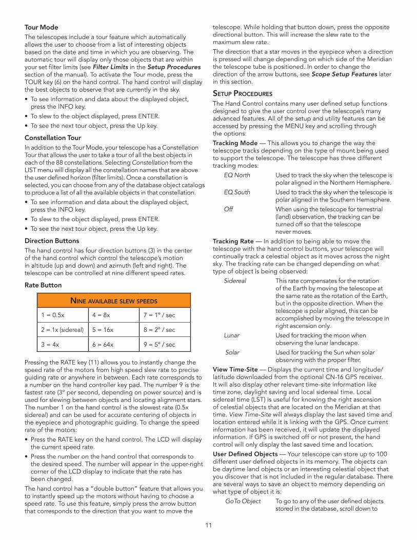
Pressing the RATE key (11) allows you to instantly change the speed rate of the motors from high speed slew rate to precise guiding rate or anywhere in between . Each rate corresponds to a number on the hand controller key pad . The number 9 is the fastest rate (3º per second, depending on power source) and is used for slewing between objects and locating alignment stars . The number 1 on the hand control is the slowest rate (0 .5x sidereal) and can be used for accurate centering of objects in the eyepiece and photographic guiding . To change the speed rate of the motors:
• PresstheRATEkeyonthehandcontrol.TheLCDwilldisplaythe current speed rate .
• Pressthenumberonthehandcontrolthatcorrespondstothe desired speed . The number will appear in the upper-right corner of the LCD display to indicate that the rate has been changed .
The hand control has a “double button” feature that allows you to instantly speed up the motors without having to choose a speed rate . To use this feature, simply press the arrow button that corresponds to the direction that you want to move the
telescope . While holding that button down, press the opposite directional button . This will increase the slew rate to the maximum slew rate .
The direction that a star moves in the eyepiece when a direction is pressed will change depending on which side of the Meridian the telescope tube is positioned . In order to change the direction of the arrow buttons, see Scope Setup Features later in this section .
SEtup proCEDurES
The Hand Control contains many user defined setup functions designed to give the user control over the telescope’s many advanced features . All of the setup and utility features can be accessed by pressing the MENU key and scrolling through the options:
Tracking Mode — This allows you to change the way the telescope tracks depending on the type of mount being used to support the telescope . The telescope has three different tracking modes:
EQ North Used to track the sky when the telescope is polar aligned in the Northern Hemisphere .
EQ South Used to track the sky when the telescope is polar aligned in the Southern Hemisphere .
Off When using the telescope for terrestrial (land) observation, the tracking can be turned off so that the telescope never moves .
Tracking Rate — In addition to being able to move the telescope with the hand control buttons, your telescope will continually track a celestial object as it moves across the night sky . The tracking rate can be changed depending on what type of object is being observed:
Sidereal This rate compensates for the rotation of the Earth by moving the telescope at the same rate as the rotation of the Earth, but in the opposite direction . When the telescope is polar aligned, this can be accomplished by moving the telescope in right ascension only .
Lunar Used for tracking the moon when observing the lunar landscape .
Solar Used for tracking the Sun when solar observing with the proper filter .
ViewTime-Site— Displays the current time and longitude/latitude downloaded from the optional CN-16 GPS receiver . It will also display other relevant time-site information like time zone, daylight saving and local sidereal time . Local sidereal time (LST) is useful for knowing the right ascension of celestial objects that are located on the Meridian at that time . View Time-Site will always display the last saved time and location entered while it is linking with the GPS . Once current information has been received, it will update the displayed information . If GPS is switched off or not present, the hand control will only display the last saved time and location .
User Defined Objects — Your telescope can store up to 100 different user defined objects in its memory . The objects can be daytime land objects or an interesting celestial object that you discover that is not included in the regular database . There are several ways to save an object to memory depending on what type of object it is:
GoTo Object To go to any of the user defined objects stored in the database, scroll down to
ninE availablE SlEW SpEEDS
1 = 0 .5x 4 = 8x 7 = 1º / sec
2 = 1x (sidereal) 5 = 16x 8 = 2º / sec
3 = 4x 6 = 64x 9 = 5º / sec
12
either GoTo Sky Obj or Goto Land Obj and enter the number of the object you wish to select and press ENTER . The telescope will automatically retrieve and display the coordinates before slewing to the object .
Save Sky Object Your telescope stores celestial objects to its database by saving its right ascension and declination in the sky . This way the same object can be found each time the telescope is aligned . Once a desired object is centered in the eyepiece, simply scroll to the “Save Sky Obj” command and press ENTER . The display will ask you to enter a number between 1-200 to identify the object . Press ENTER again to save this object to the database .
Save Database This feature allows you to create your own (Db) Object custom tour of database objects by
allowing you to record the current position of the telescope and save the name of the object by selecting it from any one of the database catalogs . These objects then can be accessed by selecting GoTo Sky Object.
Enter R.A. - Dec You can also store a specific set of coordinates for an object just by entering the R .A . and declination for that object . Scroll to the “Enter RA-DEC“ command and press ENTER . The display will then ask you to enter first the R .A . and then the declination of the desired object .
Save Land Object The telescope can also be used as a spotting scope on terrestrial objects . Fixed land objects can be stored by saving their altitude and azimuth relative to the location of the telescope at the time of observing . Since these objects are relative to the location of the telescope, they are only valid for that exact location . To save land objects, once again center the desired object in the eyepiece . Scroll down to the “Save Land Obj” command and press ENTER . The display will ask you to enter a number between 1-200 to identify the object . Press ENTER again to save this object to the database .
To replace the contents of any of the user defined objects, simply save a new object using one of the existing identification numbers;thetelescopewillreplacetheprevioususerdefinedobject with the current one .
Get RA/DEC — Displays the right ascension and declination for the current position of the telescope .
Goto R.A/ Dec — Allows you to input a specific R .A . and declination and slew to it .
To store a set of coordinates (R.A./Dec) permanently into the database, save it as a User Defined Object as described above.
IdentifyIdentify Mode will search any of the telescope’s database catalogs or lists and display the name and offset distances to the nearest matching objects . This feature can serve two purposes . First, it can be used to identify an unknown object in
the field of view of your eyepiece . Additionally, Identify Mode can be used to find other celestial objects that are close to the objects you are currently observing . For example, if your telescope is pointed at the brightest star in the constellation Lyra, choosing Identify and then searching the Named Star catalog will no doubt return the star Vega as the star you are observing . However, by selecting Identify and searching by the Named Object or Messier catalogs, the hand control will let you know that the Ring Nebula (M57) is approximately 6° from your current position . Searching the Double Star catalog will reveal that Epsilon Lyrae is only 1° away from Vega . To use the Identify feature:
• PresstheMenubuttonandselecttheIdentifyoption.
• UsetheUp/Downscrollkeystoselectthecatalogthatyouwould like to search .
• PressENTERtobeginthesearch.
Note: Some of the databases contain thousands of objects, and can therefore take several minutes to return the closest objects.
prECiSE Goto
The telescope has a precise goto function that can assist in finding extremely faint objects and centering objects closer to the center of the field of view for astrophotography and CCD imaging . Precise Goto automatically searches out the closest bright star to the desired object and asks the user to carefully center it in the eyepiece . The hand control then calculates the small difference between its goto position and its centered position . Using this offset, the telescope will then slew to the desired object with enhanced accuracy . To use Precise Goto:
1 . Press the MENU button and use the Up/Down keys to select Precise Goto .
• ChooseDatabase to select the object that you want to observefromanyofthedatabasecatalogslistedor;
• ChooseRA/DEC to enter a set of celestial coordinates that you wish to slew to .
2 . Once the desired object is selected, the hand control will search out and display the closest bright star to your desired object . Press ENTER to slew to the bright alignment star .
3 . Use the direction buttons to carefully center the alignment star in the eyepiece .
4 . Press ENTER to slew to the desired object .
SCopE SEtup FEaturES
Setup Time-Site — Allows the user to customize the telescope’s display by changing time and location parameters (such as time zone and daylight savings) .
Anti-backlash — All mechanical gears have a certain amount of backlash or play between the gears . This play is evident by how long it takes for a star to move in the eyepiece when the hand control arrow buttons are pressed (especially when changing directions) . The CGEM anti-backlash features allows the user to compensate for backlash by inputting a value which quickly rewinds the motors just enough to eliminate the play between gears . The amount of compensation needed dependsontheslewingrateselected;theslowertheslewingrate the longer it will take for the star to appear to move in the eyepiece . There are two values for each axis, positive and negative:
Positive is the amount of compensation applied when you press the button, in order to get the gears moving quickly without a long pause .
13
Negative is the amount of compensation applied when you release the button, winding the motors back in the other direction to resume tracking .
Normally both values should be the same . You will need to experimentwithdifferentvalues(from0-99);avaluebetween20 and 50 is usually best for most visual observing, whereas a higher value may be necessary for photographic guiding .
To set the anti-backlash value, scroll down to the anti-backlash option and press ENTER . While viewing an object in the eyepiece, observe the responsiveness of each of the four arrow buttons . Note which directions you see a pause in the star movement after the button has been pressed . Working one axis at a time, adjust the backlash settings high enough to cause immediate movement without resulting in a pronounced jump when pressing or releasing the button . Now, enter the same values for both positive and negative directions . If you notice a jump when releasing the button, but setting the values lower results in a pause when pressing the button, go with the higher value for positive, but use a lower value for negative . The telescope will remember these values and use them each time it is turned on until they are changed .
FilterLimits— When an alignment is complete, the telescope automatically knows which celestial objects are above the
horizon . As a result, when scrolling through the database lists (or selecting the Tour function), the hand control will display only those objects that are known to be above the horizon when you are observing . You can customize the object database by selecting altitude limits that are appropriate for your location and situation . For example, if you are observing from a mountainous location where the horizon is partially obscured, you can set your minimum altitude limit to read +20º . This will make sure that the hand control only displays objects that are higher in altitude than 20º .
If you want to explore the entire object database, set the maximum altitude limit to 90º and the minimum limit to –90º. This will display every object in the database lists regardless of whether it is visible in the sky from your location.
Direction Buttons — The direction a star appears to move in the eyepiece changes depending on which side of the Meridian the telescope tube is on . This can create confusion especially when guiding on a star when doing astrophotography . To compensate for this, the direction of the drive control keys can be changed . To reverse the button logic of the hand control, press the MENU button and select Direction Buttons from the Utilities menu . Use the Up/Down arrow keys (10) to select either the azimuth (right ascension) or altitude (declination) button direction and press ENTER . Select either positive or negative for both axes and press ENTER to save . Setting the azimuth button direction to positive will move the telescope in the same direction that the telescope tracks (i .e . towards the west) . Setting the altitude buttons to positive will move the telescope counterclockwise along the DEC axis .
Goto Approach — lets the user define the direction that the telescope will approach when slewing to an object . This allows the user the ability to minimize the effects of backlash when slewing from object to object . Just like with Direction Buttons, setting GoTo Approach to positive will make the telescope approach an object from the same direction as tracking (west) for azimuth and counterclockwise in declination . Declination Goto approach will only apply while the telescope tube is on one side of the Meridian . Once the tube passes over to the other side of the Meridian, the Goto approach will need to be reversed .
To change the Goto approach direction, simply choose Goto Approach from the Scope Setup menu, select either Altitude or Azimuth approach, choose positive or negative and press ENTER .
In order to minimize the affect of gear backlash on pointing accuracy, the settings for Button Direction should ideally match the settings for GoTo Approach. By default, using the up and right direction buttons to center alignment stars will automatically eliminate much of the backlash in the gears. If you change the Goto approach of your telescope it is not necessary to change the Button Direction as well. Simply take notice of the direction the telescope moves when completing its final goto approach. If the telescope approaches its alignment star from the west (negative azimuth) and clockwise (negative altitude) then make sure that the buttons used to center the alignment stars also move the telescope in the same directions.
Autoguide Rate — Allows the user to set an autoguide rate as a percentage of sidereal rate . This is helpful when calibrating your telescope to a CCD autoguider for long exposure photography .
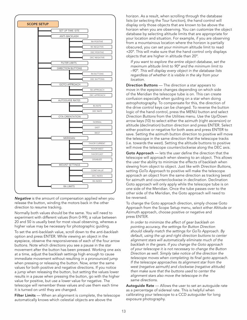
SCOPE SETUP
SET UP TIME -SITE
ANTI-BACKLASH
FILTER LIMITS
DIRECTION BUTTONS
GOTO APPROACH
AUTOGUIDE RATES
OTA ORIENTATION
MERIDIAN
MOUNT SETTINGS
RA POSITIVE
RA NEGATIVE
DEC POSITIVE
DEC NEGATIVE
RA BUTTONS
DEC BUTTONS
RA LIMITS
RA APPROACH
DEC APPROACH
RA RATE
DEC RATE
NORMAL
EAST
WEST
FAVOR CURRENT
FAVOR WEST
FAVOR EAST
DISABLED
CONE VALUE
DEC INDEX
RA INDEX
14
OTA Orientation — Some users may wish to use an optional tandem bar adapter which allows you to attach to the mount two optical tubes at the same time . When most tandem bars are attached to a mount, the optical tubes are positioned at a 90 degree angle from the standard configuration . In order for the mount to be successfully aligned with the stars, it must know that a tandem bar is being used and in which direction the optical tube(s) are positioned (East or West) when beginning an alignment .
The tandem option must be set before beginning any of the initial star alignments . To set this option, go to the Scope Setup menu and select the Tandem option and press ENTER . Then select from one of the following options:
• East — If the attached optical tubes are facing towards the east when the declination index makers are align, select East .
•West — If the attached optical tubes are facing towards the west when the declination index makers are align, select West .
•Normal — If the tandem bar is no longer being used, select “normal” to turn off this feature .
Meridian — This feature instructs the mount on how to respond when it is slewing to objects that are accessible from both sides of the Meridian . See figure 3-3 for a definition of “Meridian” . The Meridian feature allows the telescope tube to remain on a desired side of the mount when slewing, and continue to track according to the RA slew limits the user has set . See RA Limits below . The Meridian feature allows for four choices:
• FavorCurrent — Allows the mount to favor whatever side of the mount that it is currently on when slewing to objects close to the Meridian . For example, if you RA slew limits are set to allow the mount to track 10 degrees past the meridian, then the telescope will continue to stay on its current side of the Meridian when slewing to objects that are as far as 10 degrees beyond your Meridian .
• FavorWest — If the target object is accessible from both sides of the mount, selecting “Favor West” instructs the telescope to point to the object as if it were on the west side of the meridian . The optical tube will then be positioned on the east side of the mount and pointing west .
• FavorEast — If the target object is accessible from both sides of the mount, selecting “Favor East” instructs the telescope to point to the object as if it were on the east side of the meridian . The optical tube will then be positioned on the west side of the mount and pointing east .
•Disable — This is the default setting, which instructs the mount to always swing around to the other side of the pier as required to view objects on the opposite side of the Meridian . However once at the desired object, the mount will continue to track past the Meridian according the RA slew limits that have been set .
Mount Settings — Once the mount setting have been calibrated (see Utilities section below) the values are stored and displayed in the hand control . It is not recommended that the calibration values be changed, however each setting can be changed if necessary to improve the performance of the telescope .
•Cone Value – This is the cone error value set when Utilities / Calibrate Mount / DEC Switch - Cone is carried out .
•DEC Index - This is the declination index error value that is stored when calibration stars are added after your initial star alignment .
• RA Index - This is the R .A . switch error value set when Utilities / Calibrate Mount / R .A . Switch is carried out .
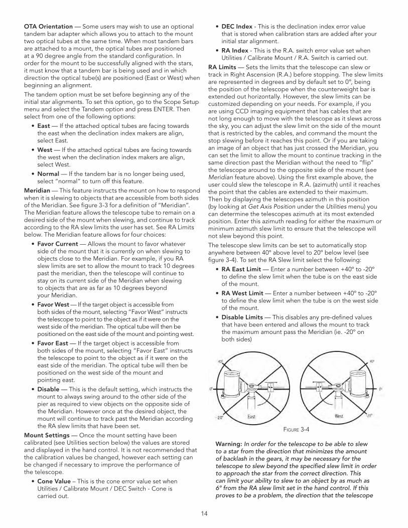
RA Limits — Sets the limits that the telescope can slew or track in Right Ascension (R .A .) before stopping . The slew limits are represented in degrees and by default set to 0º, being the position of the telescope when the counterweight bar is extended out horizontally . However, the slew limits can be customized depending on your needs . For example, if you are using CCD imaging equipment that has cables that are not long enough to move with the telescope as it slews across the sky, you can adjust the slew limit on the side of the mount that is restricted by the cables, and command the mount the stop slewing before it reaches this point . Or if you are taking an image of an object that has just crossed the Meridian, you can set the limit to allow the mount to continue tracking in the same direction past the Meridian without the need to “flip” the telescope around to the opposite side of the mount (see Meridian feature above) . Using the first example above, the user could slew the telescope in R .A . (azimuth) until it reaches the point that the cables are extended to their maximum . Then by displaying the telescopes azimuth in this position (by looking at Get Axis Position under the Utilities menu) you can determine the telescopes azimuth at its most extended position . Enter this azimuth reading for either the maximum or minimum azimuth slew limit to ensure that the telescope will not slew beyond this point .
The telescope slew limits can be set to automatically stop anywhere between 40º above level to 20º below level (see figure 3-4) . To set the RA Slew limit select the following:
• RA East Limit — Enter a number between +40º to -20º to define the slew limit when the tube is on the east side of the mount .
• RAWestLimit — Enter a number between +40º to -20º to define the slew limit when the tube is on the west side of the mount .
•Disable Limits — This disables any pre-defined values that have been entered and allows the mount to track the maximum amount pass the Meridian (ie . -20º on both sides)
Warning: In order for the telescope to be able to slew to a star from the direction that minimizes the amount of backlash in the gears, it may be necessary for the telescope to slew beyond the specified slew limit in order to approach the star from the correct direction. This can limit your ability to slew to an object by as much as 6º from the RA slew limit set in the hand control. If this proves to be a problem, the direction that the telescope
Figure 3-4
15
takes to center an object can be changed. To change the telescopes slewing direction, see Goto Approach under the Scope Setup menu.
utility FEaturES
Scrolling through the MENU (9) options will also provide access to several advanced utility functions within the telescope such as;CalibrateMount,Hibernateaswellasmanyothers.
Calibrate Mount — In order to optimize the performance and pointing accuracy of the telescope, the mount has built-in calibration routines allowing it to compensate for mechanical variation inherent in every German equatorial mount . Each calibration is completely automatic and in most cases only needs to be performed once . It is highly recommended that you take a few minutes to go through the mount calibration procedures .
• R.A.switch — this procedure records the offset error when the right ascension index mark is aligned at start-up . Calibrating the R .A . Index will improve the accuracy of your initial star alignments when aligning the telescope in the future .
•GoTo Calibration — Goto Calibration is a useful tool when attaching heavy visual or photographic accessories to the telescope . Goto Calibration calculates the amount of distance and time it takes for the mount to complete its final slow goto when slewing to an object . Changing the balance of the telescope can prolong the time it takes to complete the final slew . Goto Calibration takes into account any slight imbalances and changes the final goto distance to compensate .
Home Position — The telescopes “home” position is a user-definable position that is used to store the telescope when not in use . The home position is useful when storing the telescope in a permanent observatory facility . By default the Home position is the same as the index position used when aligning the mount .
To set the Home position for your mount simply use the arrow buttons on the hand control to move the telescope mount to the desired position . Select the Set option and press Enter .
Select the Goto option to slew the telescope back to the Home position at any time .
Light Control — This feature allows you to turn off both the red key pad light and LCD display for daytime use to conserve power and to help preserve your night vision .
FactorySettings— Returns the telecope’s hand control to its original factory settings . Parameters such as backlash compensation values, initial date and time, longitude/latitude along with slew and filter limits will be reset . However, stored parameters such as user defined objects will remain saved even when Factory Settings is selected . The hand control will ask you to press the “0” key before returning to the factory default setting .
Version — Selecting this option will allow you to see the current version number of the hand control and motor control The first set of numbers indicate the hand control software version . For the motor control, the hand control will display twosetsofnumbers;thefirstnumbersareforazimuthandthesecond set are for altitude .
Get Axis Position — Displays the relative altitude and azimuth for the current position of the telescope .
Goto Axis Position — Allows you to enter a specific altitude and azimuth position and slew to it .
Hibernate — Hibernate allows the telescope to be completely powered down and still retain its alignment when turned back on . This not only saves power, but is ideal for those that have their telescopes permanently mounted or leave their telescope in one location for long periods of time . To place your telescope in Hibernate mode:
1 . Select Hibernate from the Utility Menu .
2 . Move the telescope to a desire position and press ENTER .
3 . Power off the telescope . Remember to never move your telescope manually while in Hibernate mode .
Once the telescope is powered on again the display will read Wake Up . After pressing Enter you have the option of scrolling through the time/site information to confirm the current setting . Press ENTER to wake up the telescope .
Pressing UNDO at the Wake Up screen allows you to explore many of the features of the hand control without waking the telescope up from hibernate mode. To wake up the telescope after UNDO has been pressed, select Hibernate from the Utility menu and press ENTER. Do not use the direction buttons to move the telescope while in hibernate mode.
Sun Menu For safety purposes the Sun will not be displayed as a database object unless it is first enabled . The enable the Sun, go to the Sun Menu and press ENTER . The Sun will now be displayed in the Planets catalog as can be used as an alignment object when using the Solar System Alignment method . To remove the Sun from displaying on the hand control, once again select the Sun Menu from the Utilities Menu and press ENTER .
Scrolling MenuThis menus allows you to change the rate of speed that the text scrolls across the hand control display .
• PresstheUp(number6)buttontoincreasethespeedofthe text .
• PresstheDown(number9)buttontodecreasethespeed of the text .
SEt Mount poSition
The Set Mount Position menu can be used to maintain your alignment in cases where you wish to disengaged the clutches or similar situation . For instance, you might use this feature if you needed to rebalance the mount after having completed an alignment . To set the mount position simply slew to a bright star in the named star list then select Set Mount Position . The hand control will sync on the star by asking you to center the star in the eyepiece and pressing the Align button . Once synced on the star, you are free to manually move the mount in both axes in order to rebalance . When you are ready to slew the telescope to your next object, just remember to manually return the tube to the same bright star and carefully center it in the eyepiece . Using this tool will invalidate the PEC index .
Turn On/Off GPS — If using your telescope with the optional GPS accessory (see Optional Accessories section of the manual), you will need to turn the GPS on the first time you use the accessory . If you want to use the telescope’s database to find the coordinates of a celestial object for a future or past dates you would need to turn the GPS off in order to manually enter a time other than the present .
Turn On/Off RTC — Allows you to turn off the telescopes internal real time clock . When aligning, the telescope still receives time information from the RTC . If you want to use the
16
hand control database to find the coordinates of a celestial object for a future or past dates you would need to turn the RTC off in order to manually enter a time other than the present .
PeriodicErrorCorrection(PEC)— PEC is designed to improve photographic quality by reducing the amplitude of
the worm gear errors and improving the tracking accuracy of the drive . This feature is for advanced astrophotography and is used when your telescope is accurately polar aligned . For more information on using PEC, see the section on “Astrophotography .”
UTILITIES
CALIBRATE MOUNT
HOME POSTION
LIGHTS CONTROL
FACTORY SETTINGS
VERSION
GET AXI S POSITION
GOTO AXIS POSITION
HIBERNATE
SUN MENU
SCROLLING MENU
SET MOUNT POSITION
TURN ON/OFF GPS
PEC
GOTO
SET
GOTO
RA SWITCH
KEYPAD LEVEL
DISPLAY LEVEL
RECORD
PLAYBACK
TURN ON/OFF RTC
MENU
TRACKING
MODE
RATE
EQ NORTH
EQ SOUTH
SIDEREAL
SOLAR
LUNAR
UTILITIES
CALIBRATE MOUNT
SCOPE SETUP
VIEW TIME -SITE
SETUP TIME -SITE
HOME POSITION
ANTI-BACKLASH
FILT ER LIMITS
DIRECTION BUTTONS
GOTO APPROACH
AUTOGUIDE RATES
OTA ORIENTATION
MERIDIAN
LIGHTS CONTROL
FACTORY SETTINGS
VERSION
GET AXI S POSITION
GOTO AXIS POSITION
HIBERNATE
SUN MENU
SCROLLING MENU
MOUNT SETTINGS
R.A. LIMITS
SET MOUNT POSITION
TURN ON/OFF GPS
PEC
USER OBJECTS
IDENTIFY
GOTO RA & DEC
GET RA & DEC
PRECISE GOTO
GOTO SKY OBJECT
SAVE SKY OBJECT
SAVE DB OBJECT
ENTER RA & DEC
GOTO LAND OBJECT
SAVE LAND OBJECT
TURN ON/OFF RTC
ALIGN MENT
SELECT LOCATION
ENTER DATE – MM/DD/YY
TIME ZONE
DLS/ST
ENTER TIM E
SET TO INDEX
TWO STAR ALIGN
SOLAR SYSTEM ALIGN
LAST ALIGNMENT
QUICK ALIGN
ONE STAR ALIGN
LIST
NAME STAR
NGC
SAO
SOLAR SYSTEM
TOUR
VARIABLE STARS
ABELL
ASTERISM
CALDWELL
CCD OBJECTS
CONSTELLATIONS
DOUBLE STARS
IC
MESSIER
NAMED OBJECT
ALIGN
ALIGNMENT STARS
UNDO SYNC
SYNC
POLAR ALIGN
CALIB. STARS
ALIGN MOUNT
DISPLAY ALIGN
17
UTILITIES
CALIBRATE MOUNT
HOME POSTION
LIGHTS CONTROL
FACTORY SETTINGS
VERSION
GET AXI S POSITION
GOTO AXIS POSITION
HIBERNATE
SUN MENU
SCROLLING MENU
SET MOUNT POSITION
TURN ON/OFF GPS
PEC
GOTO
SET
GOTO
RA SWITCH
KEYPAD LEVEL
DISPLAY LEVEL
RECORD
PLAYBACK
TURN ON/OFF RTC
MENU
TRACKING
MODE
RATE
EQ NORTH
EQ SOUTH
SIDEREAL
SOLAR
LUNAR
UTILITIES
CALIBRATE MOUNT
SCOPE SETUP
VIEW TIME -SITE
SETUP TIME -SITE
HOME POSITION
ANTI-BACKLASH
FILT ER LIMITS
DIRECTION BUTTONS
GOTO APPROACH
AUTOGUIDE RATES
OTA ORIENTATION
MERIDIAN
LIGHTS CONTROL
FACTORY SETTINGS
VERSION
GET AXI S POSITION
GOTO AXIS POSITION
HIBERNATE
SUN MENU
SCROLLING MENU
MOUNT SETTINGS
R.A. LIMITS
SET MOUNT POSITION
TURN ON/OFF GPS
PEC
USER OBJECTS
IDENTIFY
GOTO RA & DEC
GET RA & DEC
PRECISE GOTO
GOTO SKY OBJECT
SAVE SKY OBJECT
SAVE DB OBJECT
ENTER RA & DEC
GOTO LAND OBJECT
SAVE LAND OBJECT
TURN ON/OFF RTC
ALIGN MENT
SELECT LOCATION
ENTER DATE – MM/DD/YY
TIME ZONE
DLS/ST
ENTER TIM E
SET TO INDEX
TWO STAR ALIGN
SOLAR SYSTEM ALIGN
LAST ALIGNMENT
QUICK ALIGN
ONE STAR ALIGN
LIST
NAME STAR
NGC
SAO
SOLAR SYSTEM
TOUR
VARIABLE STARS
ABELL
ASTERISM
CALDWELL
CCD OBJECTS
CONSTELLATIONS
DOUBLE STARS
IC
MESSIER
NAMED OBJECT
ALIGN
ALIGNMENT STARS
UNDO SYNC
SYNC
POLAR ALIGN
CALIB. STARS
ALIGN MOUNT
DISPLAY ALIGN
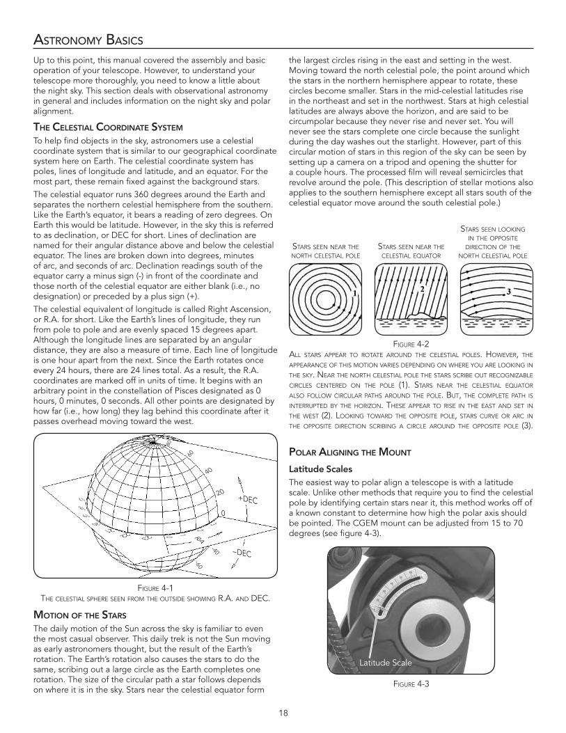
18
asTronomy basICs
Up to this point, this manual covered the assembly and basic operation of your telescope . However, to understand your telescope more thoroughly, you need to know a little about the night sky . This section deals with observational astronomy in general and includes information on the night sky and polar alignment .
thE CElEStial CoorDinatE SyStEM
To help find objects in the sky, astronomers use a celestial coordinate system that is similar to our geographical coordinate system here on Earth . The celestial coordinate system has poles, lines of longitude and latitude, and an equator . For the most part, these remain fixed against the background stars .
The celestial equator runs 360 degrees around the Earth and separates the northern celestial hemisphere from the southern . Like the Earth’s equator, it bears a reading of zero degrees . On Earth this would be latitude . However, in the sky this is referred to as declination, or DEC for short . Lines of declination are named for their angular distance above and below the celestial equator . The lines are broken down into degrees, minutes of arc, and seconds of arc . Declination readings south of the equator carry a minus sign (-) in front of the coordinate and those north of the celestial equator are either blank (i .e ., no designation) or preceded by a plus sign (+) .
The celestial equivalent of longitude is called Right Ascension, or R .A . for short . Like the Earth’s lines of longitude, they run from pole to pole and are evenly spaced 15 degrees apart . Although the longitude lines are separated by an angular distance, they are also a measure of time . Each line of longitude is one hour apart from the next . Since the Earth rotates once every 24 hours, there are 24 lines total . As a result, the R .A . coordinates are marked off in units of time . It begins with an arbitrary point in the constellation of Pisces designated as 0 hours, 0 minutes, 0 seconds . All other points are designated by how far (i .e ., how long) they lag behind this coordinate after it passes overhead moving toward the west .
Motion oF thE StarS
The daily motion of the Sun across the sky is familiar to even the most casual observer . This daily trek is not the Sun moving as early astronomers thought, but the result of the Earth’s rotation . The Earth’s rotation also causes the stars to do the same, scribing out a large circle as the Earth completes one rotation . The size of the circular path a star follows depends on where it is in the sky . Stars near the celestial equator form
the largest circles rising in the east and setting in the west . Moving toward the north celestial pole, the point around which the stars in the northern hemisphere appear to rotate, these circles become smaller . Stars in the mid-celestial latitudes rise in the northeast and set in the northwest . Stars at high celestial latitudes are always above the horizon, and are said to be circumpolar because they never rise and never set . You will never see the stars complete one circle because the sunlight during the day washes out the starlight . However, part of this circular motion of stars in this region of the sky can be seen by setting up a camera on a tripod and opening the shutter for a couple hours . The processed film will reveal semicircles that revolve around the pole . (This description of stellar motions also applies to the southern hemisphere except all stars south of the celestial equator move around the south celestial pole .)
polar aliGninG thE Mount
Latitude ScalesThe easiest way to polar align a telescope is with a latitude scale . Unlike other methods that require you to find the celestial pole by identifying certain stars near it, this method works off of a known constant to determine how high the polar axis should be pointed . The CGEM mount can be adjusted from 15 to 70 degrees (see figure 4-3) .
210
32019
18
17
21 22 23
60
-60
-40
40
20
0
Figure 4-1 the Celestial sPhere seen FroM the outsiDe showing r.a. anD DeC.
stars seen near the north Celestial Pole
stars seen near the Celestial equator
stars seen looking in the oPPosite
DireCtion oF the north Celestial Pole
Figure 4-2all stars aPPear to rotate arounD the Celestial Poles. however, the aPPearanCe oF this Motion varies DePenDing on where you are looking in the sky. near the north Celestial Pole the stars sCribe out reCognizable CirCles CentereD on the Pole (1). stars near the Celestial equator also Follow CirCular Paths arounD the Pole. but, the CoMPlete Path is interruPteD by the horizon. these aPPear to rise in the east anD set in the west (2). looking towarD the oPPosite Pole, stars Curve or arC in the oPPosite DireCtion sCribing a CirCle arounD the oPPosite Pole (3).
Figure 4-3
Latitude Scale
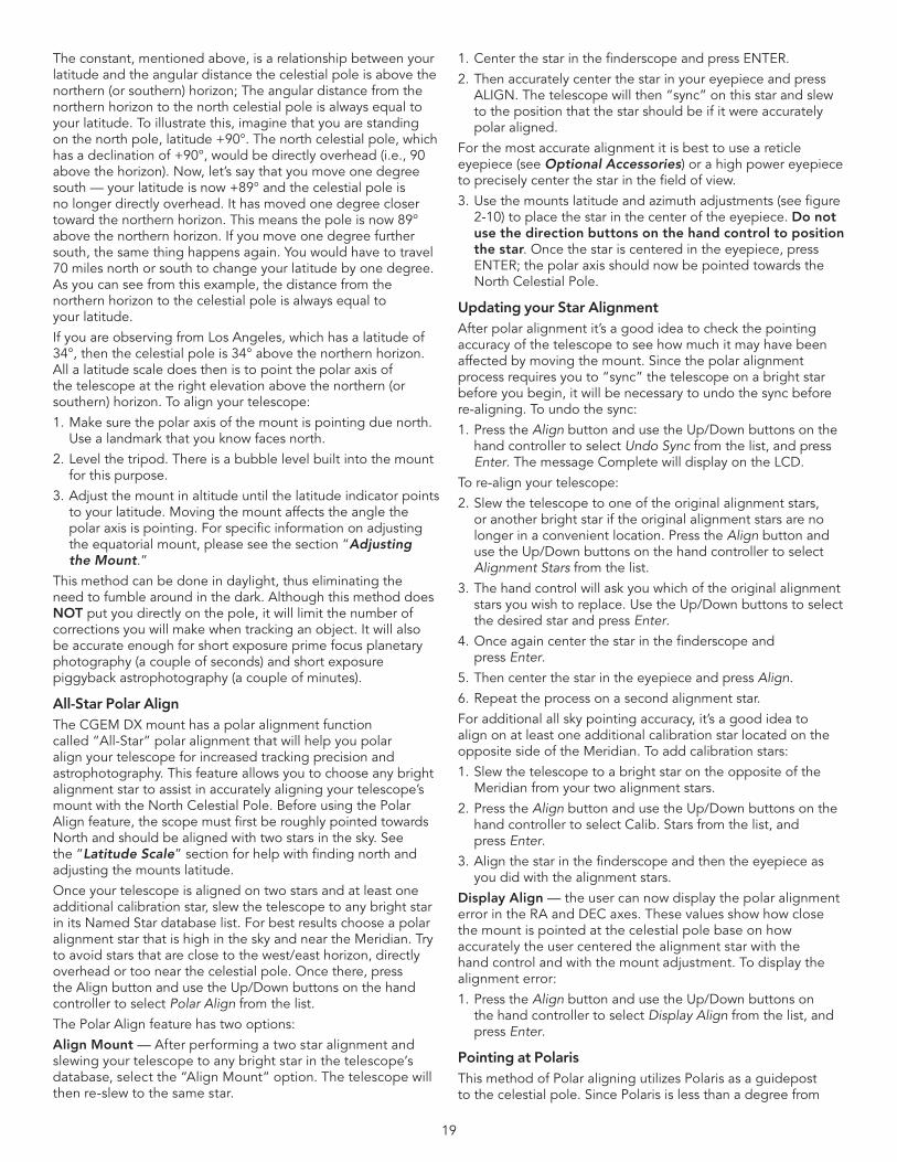
19
The constant, mentioned above, is a relationship between your latitude and the angular distance the celestial pole is above the northern(orsouthern)horizon;Theangulardistancefromthenorthern horizon to the north celestial pole is always equal to your latitude . To illustrate this, imagine that you are standing on the north pole, latitude +90° . The north celestial pole, which has a declination of +90°, would be directly overhead (i .e ., 90 above the horizon) . Now, let’s say that you move one degree south — your latitude is now +89° and the celestial pole is no longer directly overhead . It has moved one degree closer toward the northern horizon . This means the pole is now 89° above the northern horizon . If you move one degree further south, the same thing happens again . You would have to travel 70 miles north or south to change your latitude by one degree . As you can see from this example, the distance from the northern horizon to the celestial pole is always equal to your latitude .
If you are observing from Los Angeles, which has a latitude of 34°, then the celestial pole is 34° above the northern horizon . All a latitude scale does then is to point the polar axis of the telescope at the right elevation above the northern (or southern) horizon . To align your telescope:
1 . Make sure the polar axis of the mount is pointing due north . Use a landmark that you know faces north .
2 . Level the tripod . There is a bubble level built into the mount for this purpose .
3 . Adjust the mount in altitude until the latitude indicator points to your latitude . Moving the mount affects the angle the polar axis is pointing . For specific information on adjusting the equatorial mount, please see the section “Adjusting the Mount .”
This method can be done in daylight, thus eliminating the need to fumble around in the dark . Although this method does NOT put you directly on the pole, it will limit the number of corrections you will make when tracking an object . It will also be accurate enough for short exposure prime focus planetary photography (a couple of seconds) and short exposure piggyback astrophotography (a couple of minutes) .
All-Star Polar Align The CGEM DX mount has a polar alignment function called “All-Star” polar alignment that will help you polar align your telescope for increased tracking precision and astrophotography . This feature allows you to choose any bright alignment star to assist in accurately aligning your telescope’s mount with the North Celestial Pole . Before using the Polar Align feature, the scope must first be roughly pointed towards North and should be aligned with two stars in the sky . See the “Latitude Scale” section for help with finding north and adjusting the mounts latitude .
Once your telescope is aligned on two stars and at least one additional calibration star, slew the telescope to any bright star in its Named Star database list . For best results choose a polar alignment star that is high in the sky and near the Meridian . Try to avoid stars that are close to the west/east horizon, directly overhead or too near the celestial pole . Once there, press the Align button and use the Up/Down buttons on the hand controller to select Polar Align from the list .
The Polar Align feature has two options:
Align Mount — After performing a two star alignment and slewing your telescope to any bright star in the telescope’s database, select the “Align Mount” option . The telescope will then re-slew to the same star .
1 . Center the star in the finderscope and press ENTER .
2 . Then accurately center the star in your eyepiece and press ALIGN . The telescope will then “sync” on this star and slew to the position that the star should be if it were accurately polar aligned .
For the most accurate alignment it is best to use a reticle eyepiece (see Optional Accessories) or a high power eyepiece to precisely center the star in the field of view .
3 . Use the mounts latitude and azimuth adjustments (see figure 2-10) to place the star in the center of the eyepiece . Do not use the direction buttons on the hand control to position the star . Once the star is centered in the eyepiece, press ENTER;thepolaraxisshouldnowbepointedtowardstheNorth Celestial Pole .
Updating your Star AlignmentAfter polar alignment it’s a good idea to check the pointing accuracy of the telescope to see how much it may have been affected by moving the mount . Since the polar alignment process requires you to “sync” the telescope on a bright star before you begin, it will be necessary to undo the sync before re-aligning . To undo the sync:
1 . Press the Align button and use the Up/Down buttons on the hand controller to select Undo Sync from the list, and press Enter . The message Complete will display on the LCD .
To re-align your telescope:
2 . Slew the telescope to one of the original alignment stars, or another bright star if the original alignment stars are no longer in a convenient location . Press the Align button and use the Up/Down buttons on the hand controller to select Alignment Stars from the list .
3 . The hand control will ask you which of the original alignment stars you wish to replace . Use the Up/Down buttons to select the desired star and press Enter .
4 . Once again center the star in the finderscope and press Enter .
5 . Then center the star in the eyepiece and press Align .
6 . Repeat the process on a second alignment star .
For additional all sky pointing accuracy, it’s a good idea to align on at least one additional calibration star located on the opposite side of the Meridian . To add calibration stars:
1 . Slew the telescope to a bright star on the opposite of the Meridian from your two alignment stars .
2 . Press the Align button and use the Up/Down buttons on the hand controller to select Calib . Stars from the list, and press Enter .
3 . Align the star in the finderscope and then the eyepiece as you did with the alignment stars .
Display Align — the user can now display the polar alignment error in the RA and DEC axes . These values show how close the mount is pointed at the celestial pole base on how accurately the user centered the alignment star with the hand control and with the mount adjustment . To display the alignment error:
1 . Press the Align button and use the Up/Down buttons on the hand controller to select Display Align from the list, and press Enter .
Pointing at PolarisThis method of Polar aligning utilizes Polaris as a guidepost to the celestial pole . Since Polaris is less than a degree from
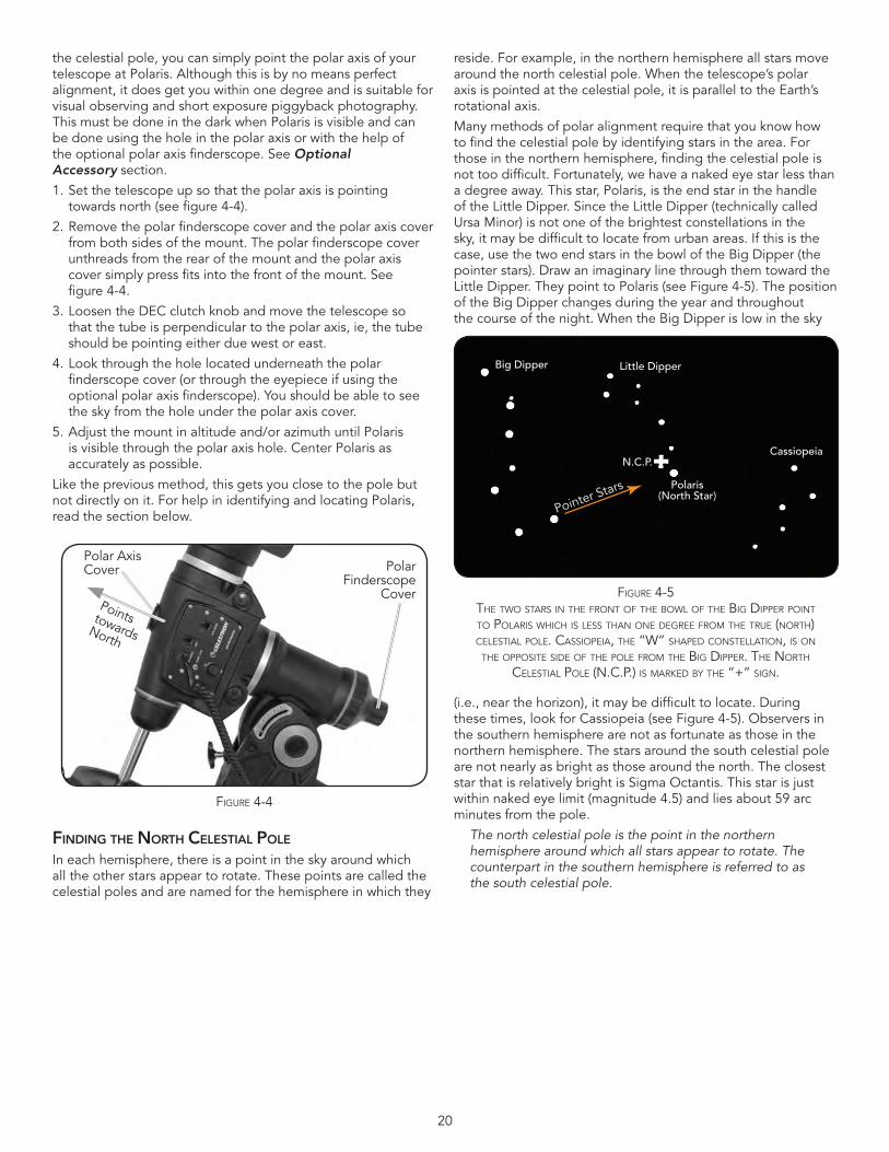
20
the celestial pole, you can simply point the polar axis of your telescope at Polaris . Although this is by no means perfect alignment, it does get you within one degree and is suitable for visual observing and short exposure piggyback photography . This must be done in the dark when Polaris is visible and can be done using the hole in the polar axis or with the help of the optional polar axis finderscope . See Optional Accessory section .
1 . Set the telescope up so that the polar axis is pointing towards north (see figure 4-4) .
2 . Remove the polar finderscope cover and the polar axis cover from both sides of the mount . The polar finderscope cover unthreads from the rear of the mount and the polar axis cover simply press fits into the front of the mount . See figure 4-4 .
3 . Loosen the DEC clutch knob and move the telescope so that the tube is perpendicular to the polar axis, ie, the tube should be pointing either due west or east .
4 . Look through the hole located underneath the polar finderscope cover (or through the eyepiece if using the optional polar axis finderscope) . You should be able to see the sky from the hole under the polar axis cover .
5 . Adjust the mount in altitude and/or azimuth until Polaris is visible through the polar axis hole . Center Polaris as accurately as possible .
Like the previous method, this gets you close to the pole but not directly on it . For help in identifying and locating Polaris, read the section below .
FinDinG thE north CElEStial polE
In each hemisphere, there is a point in the sky around which all the other stars appear to rotate . These points are called the celestial poles and are named for the hemisphere in which they
reside . For example, in the northern hemisphere all stars move around the north celestial pole . When the telescope’s polar axis is pointed at the celestial pole, it is parallel to the Earth’s rotational axis .
Many methods of polar alignment require that you know how to find the celestial pole by identifying stars in the area . For those in the northern hemisphere, finding the celestial pole is not too difficult . Fortunately, we have a naked eye star less than a degree away . This star, Polaris, is the end star in the handle of the Little Dipper . Since the Little Dipper (technically called Ursa Minor) is not one of the brightest constellations in the sky, it may be difficult to locate from urban areas . If this is the case, use the two end stars in the bowl of the Big Dipper (the pointer stars) . Draw an imaginary line through them toward the Little Dipper . They point to Polaris (see Figure 4-5) . The position of the Big Dipper changes during the year and throughout the course of the night . When the Big Dipper is low in the sky
(i .e ., near the horizon), it may be difficult to locate . During these times, look for Cassiopeia (see Figure 4-5) . Observers in the southern hemisphere are not as fortunate as those in the northern hemisphere . The stars around the south celestial pole are not nearly as bright as those around the north . The closest star that is relatively bright is Sigma Octantis . This star is just within naked eye limit (magnitude 4 .5) and lies about 59 arc minutes from the pole .
The north celestial pole is the point in the northern hemisphere around which all stars appear to rotate. The counterpart in the southern hemisphere is referred to as the south celestial pole.
Figure 4-4
Polar Axis Cover
Points towards North
Polar Finderscope
Cover
Polaris(North Star)
Big Dipper Little Dipper
CassiopeiaN.C.P.
Pointer Stars
Figure 4-5the two stars in the Front oF the bowl oF the big DiPPer Point to Polaris whiCh is less than one Degree FroM the true (north) Celestial Pole. CassioPeia, the “w” shaPeD Constellation, is on
the oPPosite siDe oF the Pole FroM the big DiPPer. the north Celestial Pole (n.C.P.) is MarkeD by the “+” sign.
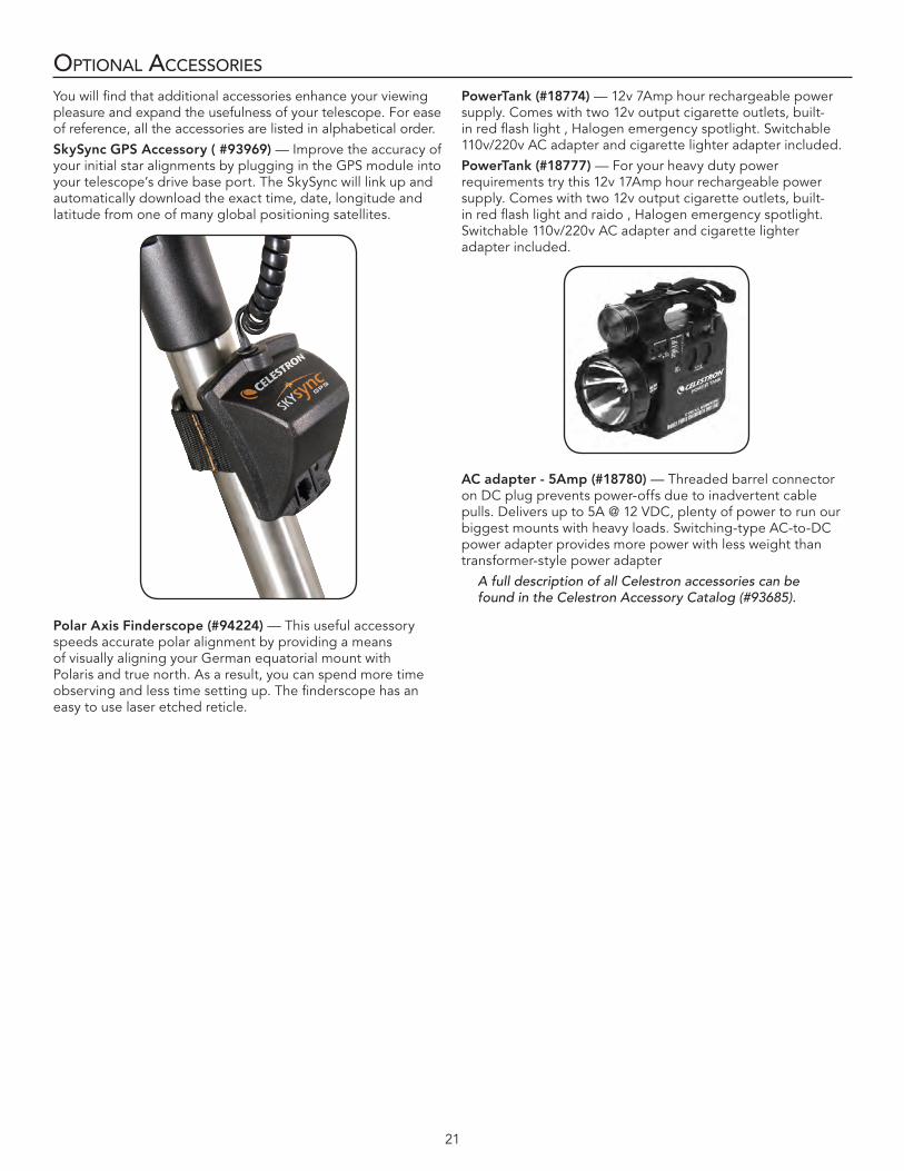
21
opTIonal aCCessorIes
You will find that additional accessories enhance your viewing pleasure and expand the usefulness of your telescope . For ease of reference, all the accessories are listed in alphabetical order .
SkySyncGPSAccessory(#93969)— Improve the accuracy of your initial star alignments by plugging in the GPS module into your telescope’s drive base port . The SkySync will link up and automatically download the exact time, date, longitude and latitude from one of many global positioning satellites .
PolarAxisFinderscope(#94224)— This useful accessory speeds accurate polar alignment by providing a means of visually aligning your German equatorial mount with Polaris and true north . As a result, you can spend more time observing and less time setting up . The finderscope has an easy to use laser etched reticle .
PowerTank(#18774)— 12v 7Amp hour rechargeable power supply . Comes with two 12v output cigarette outlets, built-in red flash light , Halogen emergency spotlight . Switchable 110v/220v AC adapter and cigarette lighter adapter included .
PowerTank(#18777)— For your heavy duty power requirements try this 12v 17Amp hour rechargeable power supply . Comes with two 12v output cigarette outlets, built-in red flash light and raido , Halogen emergency spotlight . Switchable 110v/220v AC adapter and cigarette lighter adapter included .
ACadapter-5Amp(#18780)— Threaded barrel connector on DC plug prevents power-offs due to inadvertent cable pulls . Delivers up to 5A @ 12 VDC, plenty of power to run our biggest mounts with heavy loads . Switching-type AC-to-DC power adapter provides more power with less weight than transformer-style power adapter
A full description of all Celestron accessories can be found in the Celestron Accessory Catalog (#93685).

22
CGem dX mounT Hand Control Doubleline,16characterLiquidCrystalDisplay;
19 fiber optic backlit LED buttons
Motor: Type DC Servo motors with encoders, both axes
Max Slew Speed 5º/second
Software Precision 24 bit, 0 .08 arcsec calculation
Hand Control Ports RS-232 communication port on hand control
Motor Ports Aux Port, Autoguide Ports
Tracking Rates Sidereal, Solar and Lunar
Tracking Modes EQ North & EQ South
Alignment Procedures 2-Star Align, 1-Star Align, Solar System Align, Quick Align, Last Align
Database 40,000+ objects, 100 user defined programmable objects . Enhanced information on over 200 objects .
Complete Revised NGC Catalog 7,840
Complete Messier Catalog 110
Complete IC Catalog 5,386
Complete Caldwell 109
Abell Galaxies 2,712
Solar System objects 9
Famous Asterisms 20
Selected CCD Imaging Objects 25
Selected SAO Stars 29,500
User defined (Sky Objects) 99
User defined (Land Objects) 9
Total Object Database 45,492
appendIX a – TeCHnICal speCIfICaTIons
appendIX b - Glossary of Terms
A –
Absolute The apparent magnitude that a star magnitude would have if it were observed from a standard distance of 10 parsecs, or 32 .6 light– years . The absolute magnitude of the Sun is 4 .8 . at a distance of 10 parsecs, it would just be visible on Earth on a clear moonless night away from surface light .
Airy disk The apparent size of a star’s disk produced even by a perfect optical system . Since the star can never be focused perfectly, 84% of
the light will concentrate into a single disk, and 16 % into a system of surrounding rings .
Alt–Azimuth A telescope mounting using two Mounting independent rotation axes allowing movement of the instrument in Altitude and Azimuth .
Altitude In astronomy, the altitude of a celestial object is its Angular Distance above or below the celestial horizon .
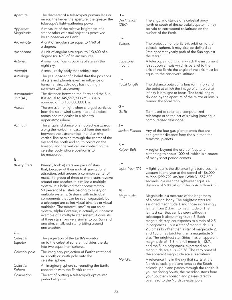
23
Aperture The diameter of a telescope’s primary lens or mirror;thelargertheaperture,thegreaterthetelescope’s light–gathering power .
Apparent A measure of the relative brightness of a Magnitude star or other celestial object as perceived by an observer on Earth .
Arc minute A unit of angular size equal to 1/60 of a degree .
Arc second A unit of angular size equal to 1/3,600 of a degree (or 1/60 of an arc minute) .
Asterism A small unofficial grouping of stars in the night sky .
Asteroid A small, rocky body that orbits a star .
Astrology The pseudoscientific belief that the positions of stars and planets exert an influence on humanaffairs;astrologyhasnothingincommon with astronomy .
Astronomical The distance between the Earth and the Sun . unit (AU) It is equal to 149,597,900 km ., usually rounded off to 150,000,000 km .
Aurora The emission of light when charged particles from the solar wind slams into and excites atoms and molecules in a planet’s upper atmosphere .
Azimuth The angular distance of an object eastwards along the horizon, measured from due north, between the astronomical meridian (the vertical line passing through the center of the sky and the north and south points on the horizon) and the vertical line containing the celestial body whose position is to be measured .
B –
Binary Stars Binary (Double) stars are pairs of stars that, because of their mutual gravitational attraction, orbit around a common center of mass . If a group of three or more stars revolve around one another, it is called a multiple system . It is believed that approximately 50 percent of all stars belong to binary or multiple systems . Systems with individual components that can be seen separately by a telescope are called visual binaries or visual multiples . The nearest “star” to our solar system, Alpha Centauri, is actually our nearest example of a multiple star system, it consists of three stars, two very similar to our Sun and one dim, small, red star orbiting around one another .
C –
Celestial The projection of the Earth’s equator Equator on to the celestial sphere . It divides the sky into two equal hemispheres .
Celestial pole The imaginary projection of Earth’s rotational axis north or south pole onto the celestial sphere .
Celestial An imaginary sphere surrounding the Earth, Sphere concentric with the Earth’s center .
Collimation The act of putting a telescope’s optics into perfect alignment .
D –
Declination The angular distance of a celestial body (DEC) north or south of the celestial equator . It may be said to correspond to latitude on the surface of the Earth .
E –
Ecliptic The projection of the Earth’s orbit on to the celestial sphere . It may also be defined as “the apparent yearly path of the Sun against the stars .”
Equatorial A telescope mounting in which the instrument mount is set upon an axis which is parallel to the axisoftheEarth;theangleoftheaxismustbe equal to the observer’s latitude .
F–
Focal length The distance between a lens (or mirror) and the point at which the image of an object at infinity is brought to focus . The focal length divided by the aperture of the mirror or lens is termed the focal ratio .
G –
GoTo Term used to refer to a computerized telescope or to the act of slewing (moving) a computerized telescope .
J –
Jovian Planets Any of the four gas giant planets that are at a greater distance form the sun than the terrestrial planets .
K –
Kuiper Belt A region beyond the orbit of Neptune extending to about 1000 AU which is a source of many short period comets .
L –
Light–Year (LY) A light–year is the distance light traverses in a vacuum in one year at the speed of 186,000 mi/sec . (299,792 km/sec .) With 31,557,600 seconds in a year, the light–year equals a distance of 5 .88 trillion miles (9 .46 trillion km) .
M –
Magnitude Magnitude is a measure of the brightness of a celestial body . The brightest stars are assigned magnitude 1 and those increasingly fainter from 2 down to magnitude 5 . The faintest star that can be seen without a telescope is about magnitude 6 . Each magnitude step corresponds to a ratio of 2 .5 in brightness . Thus a star of magnitude 1 is 2 .5 times brighter than a star of magnitude 2, and 100 times brighter than a magnitude 5 star . The brightest star, Sirius, has an apparent magnitude of –1 .6, the full moon is –12 .7, and the Sun’s brightness, expressed on a magnitude scale, is –26 .78 . The zero point of the apparent magnitude scale is arbitrary .
Meridian A reference line in the sky that starts at the North celestial pole and ends at the South celestial pole and passes through the zenith . If you are facing South, the meridian starts from your Southern horizon and passes directly overhead to the North celestial pole .
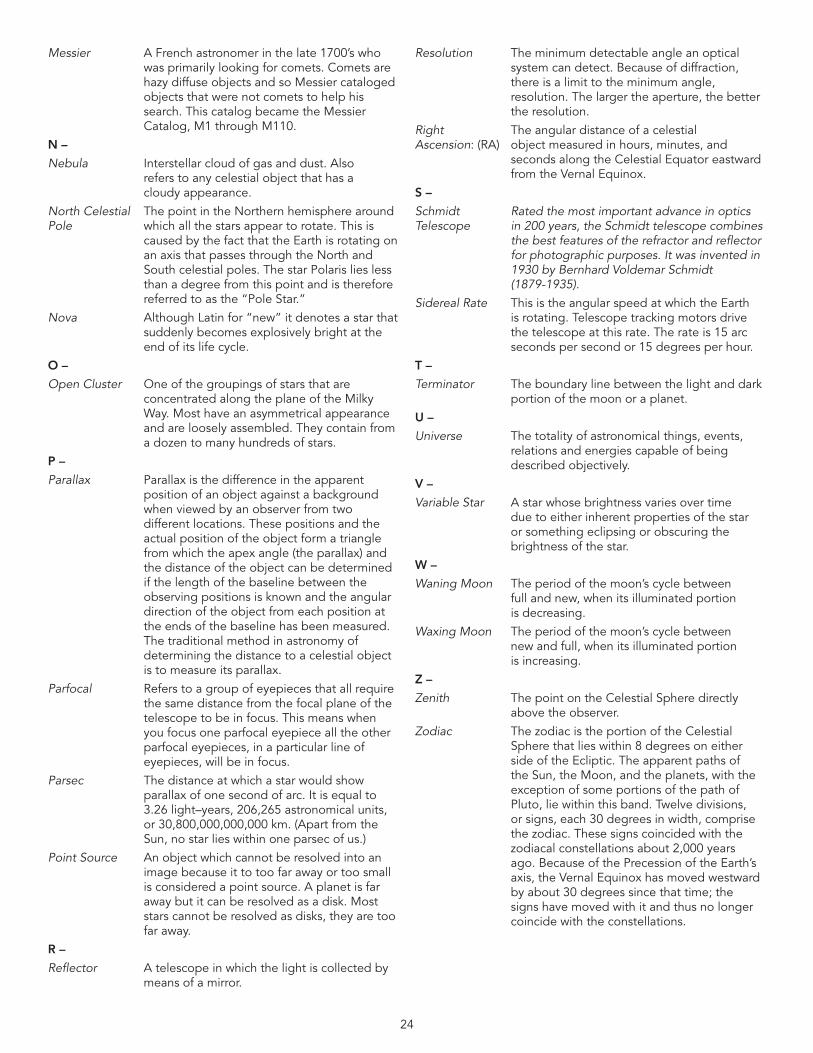
24
Messier A French astronomer in the late 1700’s who was primarily looking for comets . Comets are hazy diffuse objects and so Messier cataloged objects that were not comets to help his search . This catalog became the Messier Catalog, M1 through M110 .
N –
Nebula Interstellar cloud of gas and dust . Also refers to any celestial object that has a cloudy appearance .
North Celestial The point in the Northern hemisphere around Pole which all the stars appear to rotate . This is caused by the fact that the Earth is rotating on an axis that passes through the North and South celestial poles . The star Polaris lies less than a degree from this point and is therefore referred to as the “Pole Star .”
Nova Although Latin for “new” it denotes a star that suddenly becomes explosively bright at the end of its life cycle .
O –
Open Cluster One of the groupings of stars that are concentrated along the plane of the Milky Way . Most have an asymmetrical appearance and are loosely assembled . They contain from a dozen to many hundreds of stars .
P –
Parallax Parallax is the difference in the apparent position of an object against a background when viewed by an observer from two different locations . These positions and the actual position of the object form a triangle from which the apex angle (the parallax) and the distance of the object can be determined if the length of the baseline between the observing positions is known and the angular direction of the object from each position at the ends of the baseline has been measured . The traditional method in astronomy of determining the distance to a celestial object is to measure its parallax .
Parfocal Refers to a group of eyepieces that all require the same distance from the focal plane of the telescope to be in focus . This means when you focus one parfocal eyepiece all the other parfocal eyepieces, in a particular line of eyepieces, will be in focus .
Parsec The distance at which a star would show parallax of one second of arc . It is equal to 3 .26 light–years, 206,265 astronomical units, or 30,800,000,000,000 km . (Apart from the Sun, no star lies within one parsec of us .)
Point Source An object which cannot be resolved into an image because it to too far away or too small is considered a point source . A planet is far away but it can be resolved as a disk . Most stars cannot be resolved as disks, they are too far away .
R –
Reflector A telescope in which the light is collected by means of a mirror .
Resolution The minimum detectable angle an optical system can detect . Because of diffraction, there is a limit to the minimum angle, resolution . The larger the aperture, the better the resolution .
Right The angular distance of a celestial Ascension: (RA) object measured in hours, minutes, and seconds along the Celestial Equator eastward from the Vernal Equinox .
S –
Schmidt Rated the most important advance in optics Telescope in 200 years, the Schmidt telescope combines
the best features of the refractor and reflector for photographic purposes. It was invented in 1930 by Bernhard Voldemar Schmidt (1879-1935).
Sidereal Rate This is the angular speed at which the Earth is rotating . Telescope tracking motors drive the telescope at this rate . The rate is 15 arc seconds per second or 15 degrees per hour .
T –
Terminator The boundary line between the light and dark portion of the moon or a planet .
U –
Universe The totality of astronomical things, events, relations and energies capable of being described objectively .
V –
Variable Star A star whose brightness varies over time due to either inherent properties of the star or something eclipsing or obscuring the brightness of the star .
W–
Waning Moon The period of the moon’s cycle between full and new, when its illuminated portion is decreasing .
Waxing Moon The period of the moon’s cycle between new and full, when its illuminated portion is increasing .
Z –
Zenith The point on the Celestial Sphere directly above the observer .
Zodiac The zodiac is the portion of the Celestial Sphere that lies within 8 degrees on either side of the Ecliptic . The apparent paths of the Sun, the Moon, and the planets, with the exception of some portions of the path of Pluto, lie within this band . Twelve divisions, or signs, each 30 degrees in width, comprise the zodiac . These signs coincided with the zodiacal constellations about 2,000 years ago . Because of the Precession of the Earth’s axis, the Vernal Equinox has moved westward byabout30degreessincethattime;thesigns have moved with it and thus no longer coincide with the constellations .
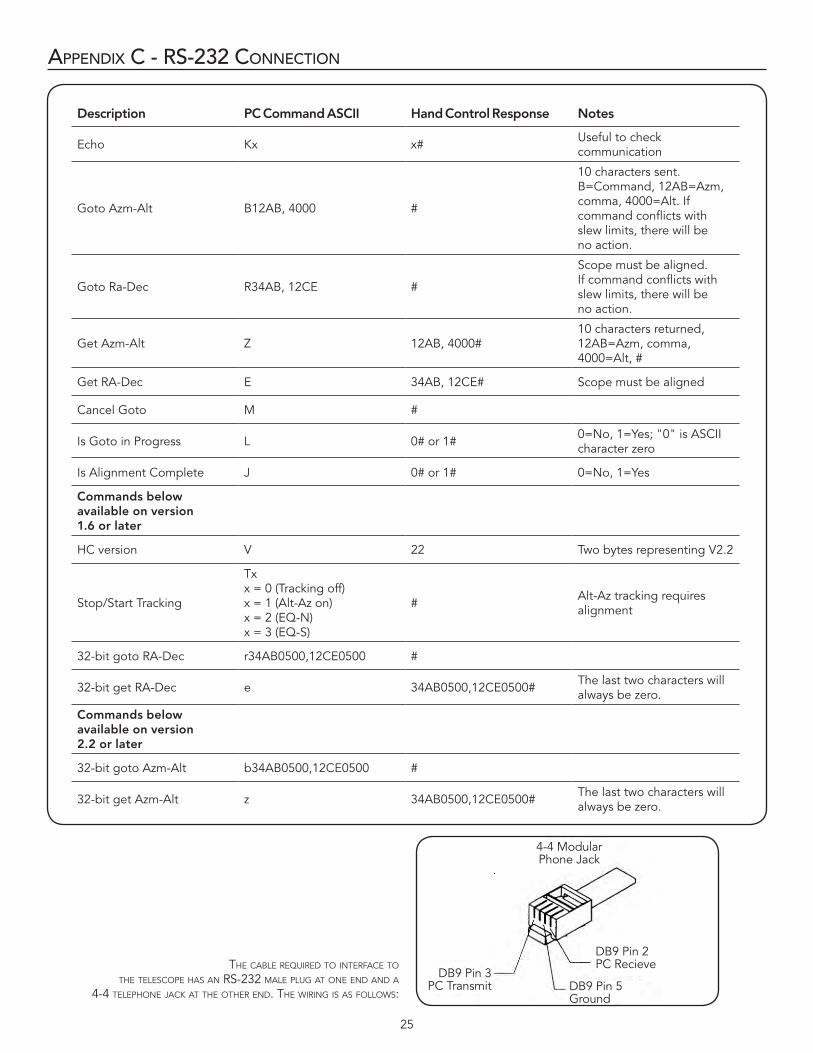
25
appendIX C - rs-232 ConneCTIon
Description PC Command ASCII Hand Control Response Notes
Echo Kx x# Useful to check communication
Goto Azm-Alt B12AB, 4000 #
10 characters sent . B=Command, 12AB=Azm, comma, 4000=Alt . If command conflicts with slew limits, there will be no action .
Goto Ra-Dec R34AB, 12CE #
Scope must be aligned . If command conflicts with slew limits, there will be no action .
Get Azm-Alt Z 12AB, 4000#10 characters returned, 12AB=Azm, comma, 4000=Alt, #
Get RA-Dec E 34AB, 12CE# Scope must be aligned
Cancel Goto M #
Is Goto in Progress L 0# or 1# 0=No,1=Yes;"0"isASCIIcharacter zero
Is Alignment Complete J 0# or 1# 0=No, 1=Yes
Commandsbelowavailableonversion 1.6 or later
HC version V 22 Two bytes representing V2 .2
Stop/Start Tracking
Tx x = 0 (Tracking off) x = 1 (Alt-Az on) x = 2 (EQ-N) x = 3 (EQ-S)
# Alt-Az tracking requires alignment
32-bit goto RA-Dec r34AB0500,12CE0500 #
32-bit get RA-Dec e 34AB0500,12CE0500# The last two characters will always be zero .
Commandsbelowavailableonversion 2.2 or later
32-bit goto Azm-Alt b34AB0500,12CE0500 #
32-bit get Azm-Alt z 34AB0500,12CE0500# The last two characters will always be zero .
the Cable requireD to interFaCe to the telesCoPe has an rs-232 Male Plug at one enD anD a
4-4 telePhone jaCk at the other enD. the wiring is as Follows:
4-4 Modular Phone Jack
DB9 Pin 3 PC Transmit
DB9 Pin 2 PC Recieve
DB9 Pin 5 Ground
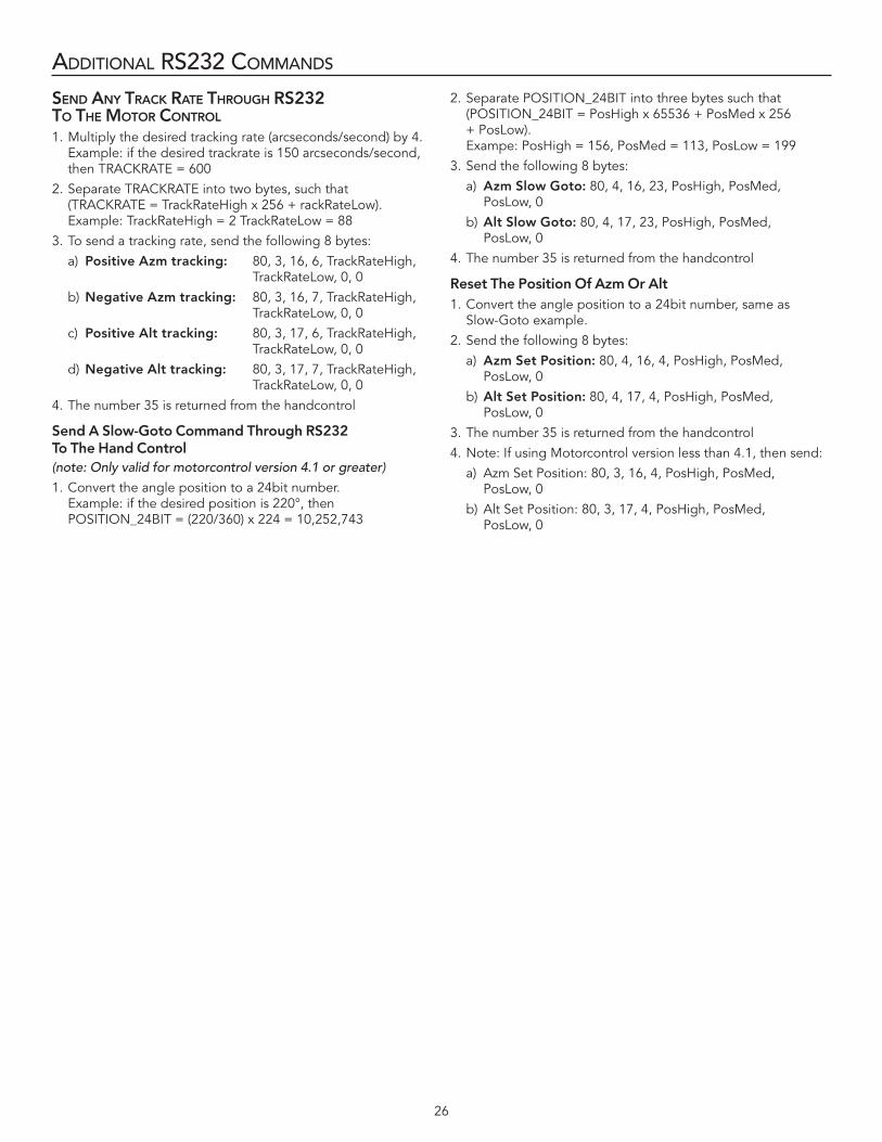
26
addITIonal rs232 Commands
SEnD any traCK ratE throuGh rS232 to thE Motor Control
1 . Multiply the desired tracking rate (arcseconds/second) by 4 . Example: if the desired trackrate is 150 arcseconds/second, then TRACKRATE = 600
2 . Separate TRACKRATE into two bytes, such that (TRACKRATE = TrackRateHigh x 256 + rackRateLow) . Example: TrackRateHigh = 2 TrackRateLow = 88
3 . To send a tracking rate, send the following 8 bytes:
a) PositiveAzmtracking: 80, 3, 16, 6, TrackRateHigh, TrackRateLow, 0, 0
b) NegativeAzmtracking: 80, 3, 16, 7, TrackRateHigh, TrackRateLow, 0, 0
c) PositiveAlttracking: 80, 3, 17, 6, TrackRateHigh, TrackRateLow, 0, 0
d) NegativeAlttracking: 80, 3, 17, 7, TrackRateHigh, TrackRateLow, 0, 0
4 . The number 35 is returned from the handcontrol
SendASlow-GotoCommandThroughRS232 To The Hand Control(note: Only valid for motorcontrol version 4.1 or greater)
1 . Convert the angle position to a 24bit number . Example: if the desired position is 220°, then POSITION_24BIT = (220/360) x 224 = 10,252,743
2 . Separate POSITION_24BIT into three bytes such that (POSITION_24BIT = PosHigh x 65536 + PosMed x 256 + PosLow) . Exampe: PosHigh = 156, PosMed = 113, PosLow = 199
3 . Send the following 8 bytes:
a) AzmSlowGoto: 80, 4, 16, 23, PosHigh, PosMed, PosLow, 0
b) AltSlowGoto: 80, 4, 17, 23, PosHigh, PosMed, PosLow, 0
4 . The number 35 is returned from the handcontrol
Reset The Position Of Azm Or Alt1 . Convert the angle position to a 24bit number, same as
Slow-Goto example .
2 . Send the following 8 bytes:
a) Azm Set Position: 80, 4, 16, 4, PosHigh, PosMed, PosLow, 0
b) Alt Set Position: 80, 4, 17, 4, PosHigh, PosMed, PosLow, 0
3 . The number 35 is returned from the handcontrol
4 . Note: If using Motorcontrol version less than 4 .1, then send:
a) Azm Set Position: 80, 3, 16, 4, PosHigh, PosMed, PosLow, 0
b) Alt Set Position: 80, 3, 17, 4, PosHigh, PosMed, PosLow, 0
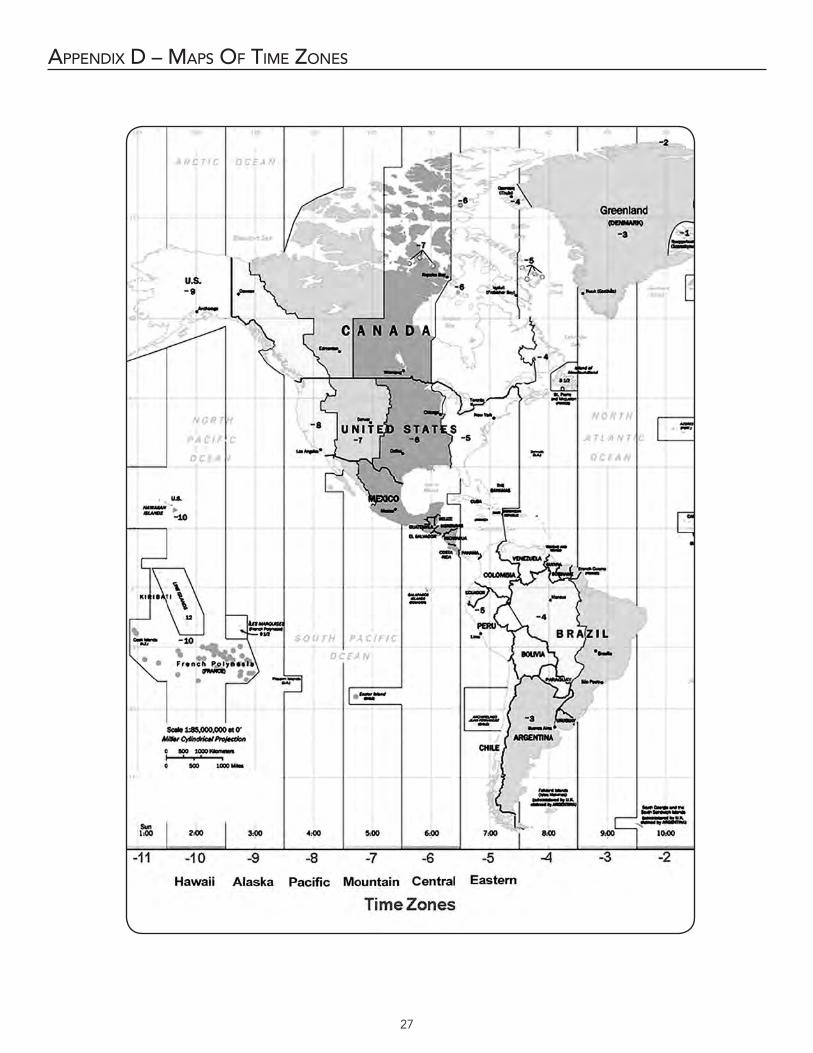
27
appendIX d – maps of TIme Zones
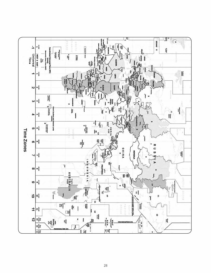
28
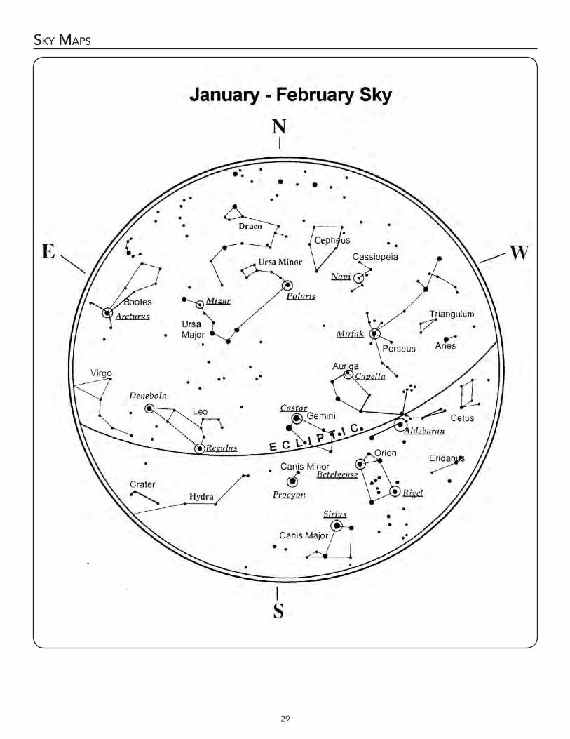
29
sky maps
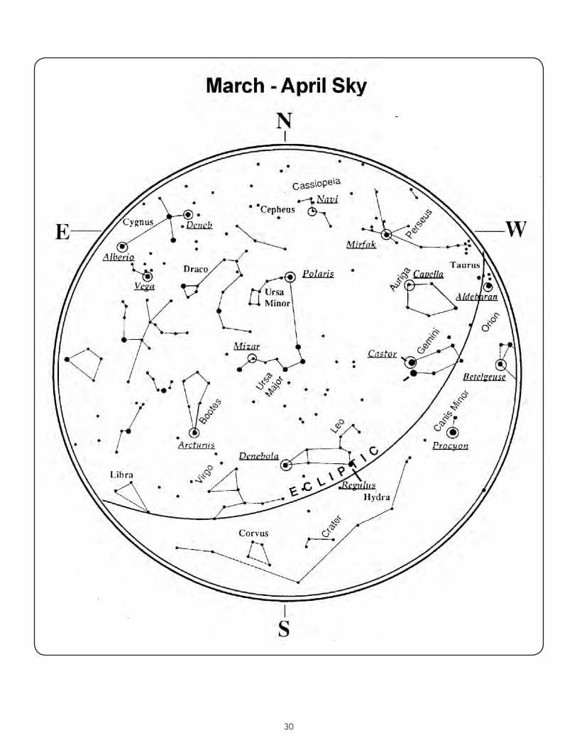
30
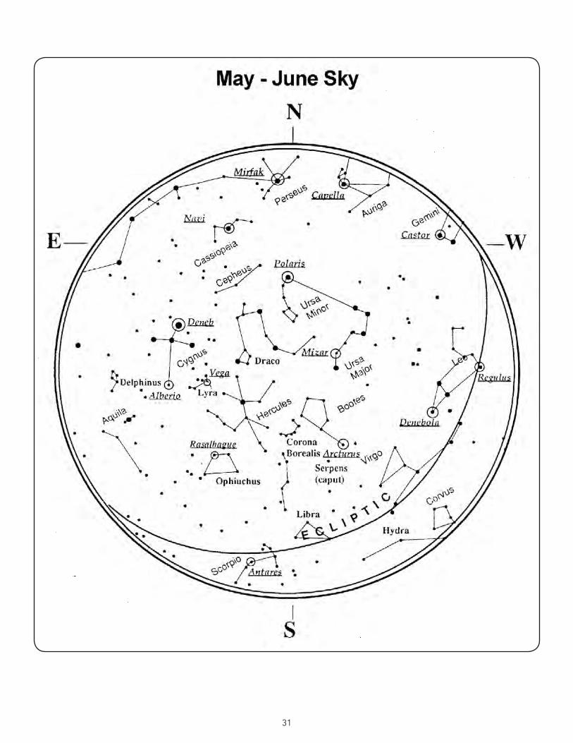
31
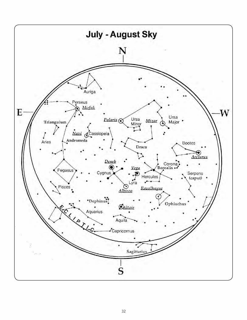
32
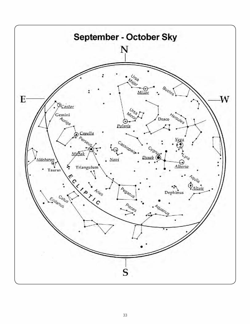
33
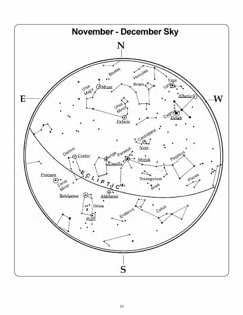
34
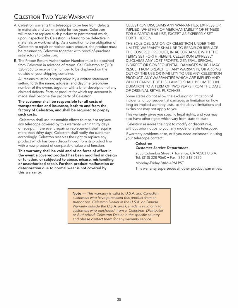
35
CelesTron Two year warranTy
A . Celestron warrants this telescope to be free from defects in materials and workmanship for two years . Celestron will repair or replace such product or part thereof which, upon inspection by Celestron, is found to be defective in materials or workmanship . As a condition to the obligation of Celestron to repair or replace such product, the product must be returned to Celestron together with proof-of-purchase satisfactory to Celestron .
B . The Proper Return Authorization Number must be obtained from Celestron in advance of return . Call Celestron at (310) 328-9560 to receive the number to be displayed on the outside of your shipping container .
All returns must be accompanied by a written statement setting forth the name, address, and daytime telephone number of the owner, together with a brief description of any claimed defects . Parts or product for which replacement is made shall become the property of Celestron .
The customer shall be responsible for all costs of transportation and insurance, both to and from the factory of Celestron, and shall be required to prepay such costs.
Celestron shall use reasonable efforts to repair or replace any telescope covered by this warranty within thirty days of receipt . In the event repair or replacement shall require more than thirty days, Celestron shall notify the customer accordingly . Celestron reserves the right to replace any product which has been discontinued from its product line with a new product of comparable value and function .
Thiswarrantyshallbevoidandofnoforceofeffectintheeventacoveredproducthasbeenmodifiedindesignor function, or subjected to abuse, misuse, mishandling orunauthorizedrepair.Further,productmalfunctionordeteriorationduetonormalwearisnotcoveredby thiswarranty.
CELESTRON DISCLAIMS ANY WARRANTIES, EXPRESS OR IMPLIED, WHETHER OF MERCHANTABILITY OF FITNESS FOR A PARTICULAR USE, EXCEPT AS EXPRESSLY SET FORTH HEREIN .
THE SOLE OBLIGATION OF CELESTRON UNDER THIS LIMITED WARRANTY SHALL BE TO REPAIR OR REPLACE THE COVERED PRODUCT, IN ACCORDANCE WITH THE TERMS SET FORTH HEREIN . CELESTRON EXPRESSLY DISCLAIMS ANY LOST PROFITS, GENERAL, SPECIAL, INDIRECT OR CONSEQUENTIAL DAMAGES WHICH MAY RESULT FROM BREACH OF ANY WARRANTY, OR ARISING OUT OF THE USE OR INABILITY TO USE ANY CELESTRON PRODUCT . ANY WARRANTIES WHICH ARE IMPLIED AND WHICH CANNOT BE DISCLAIMED SHALL BE LIMITED IN DURATION TO A TERM OF TWO YEARS FROM THE DATE OF ORIGINAL RETAIL PURCHASE .
Some states do not allow the exclusion or limitation of incidental or consequential damages or limitation on how long an implied warranty lasts, so the above limitations and exclusions may not apply to you .
This warranty gives you specific legal rights, and you may also have other rights which vary from state to state .
Celestron reserves the right to modify or discontinue, without prior notice to you, any model or style telescope .
If warranty problems arise, or if you need assistance in using your telescope contact:
Celestron Customer Service Department
2835ColumbiaStreet•Torrance,CA90503U.S.A. Tel.(310)328-9560•Fax.(310)212-5835
Monday-Friday 8AM-4PM PST
This warranty supersedes all other product warranties .
Note — This warranty is valid to U.S.A. and Canadian customers who have purchased this product from an Authorized Celestron Dealer in the U.S.A. or Canada. Warranty outside the U.S.A. and Canada is valid only to customers who purchased from a Celestron Distributor or Authorized Celestron Dealer in the specific country and please contact them for any warranty service.

2835ColumbiaStreet•Torrance,CA90503U.S.A.Telephone:310.328.9560•Fax:310.212.5835
©2011 CelestronAllrightsreserved.•PrintedinChina•01-11 (Product design and specifications are) 91528-INST•$10.00 subject to change without prior notification .)
www.celestron.com


![Zgbc F B Dmavfbg ©BBBªBBBBBBBBBBBBBBBBBB ]karatevolkhov.ru/Pervenstvo_MLBI_2018.pdf · ^h dx klZjr_ dx dx klZjr_ dx 8 - e_l FZevqbdb ^h dx\dexqbl_evgh ^h dx\dexqbl_evgh >_\hqdb](https://img.pdfslide.us/doc/110x75/5ec420b3644640007216892f/zgbc-f-b-dmavfbg-bbbbbbbbbbbbbbbbbbbbb-h-dx-klzjr-dx-dx-klzjr-dx-8-el.jpg)