Embed Size (px)
Citation preview
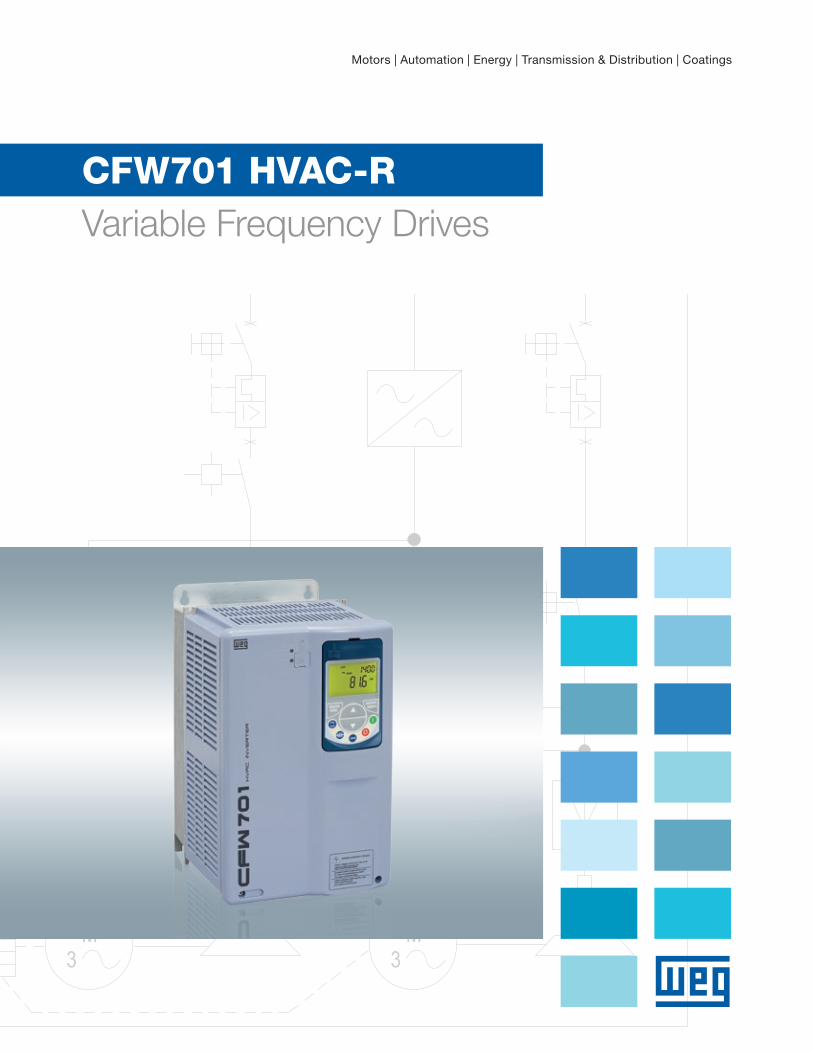
Motors | Automation | Energy | Transmission & Distribution | Coatings
CFW701 HVAC-R Variable Frequency Drives
www.weg.net
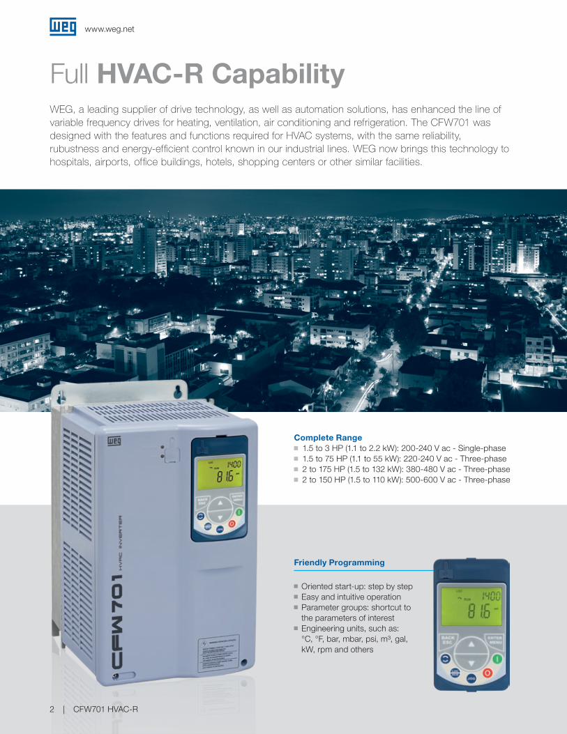
WEG, a leading supplier of drive technology, as well as automation solutions, has enhanced the line ofvariable frequency drives for heating, ventilation, air conditioning and refrigeration. The CFW701 was designed with the features and functions required for HVAC systems, with the same reliability, rubustness and energy-efficient control known in our industrial lines. WEG now brings this technology to hospitals, airports, office buildings, hotels, shopping centers or other similar facilities.
Full HVAC-R Capability
Friendly Programming
g Oriented start-up: step by stepg Easy and intuitive operation g Parameter groups: shortcut to
the parameters of interest g Engineering units, such as:
°C, °F, bar, mbar, psi, m³, gal, kW, rpm and others
Complete Range g 1.5 to 3 HP (1.1 to 2.2 kW): 200-240 V ac - Single-phase g 1.5 to 75 HP (1.1 to 55 kW): 220-240 V ac - Three-phase g 2 to 175 HP (1.5 to 132 kW): 380-480 V ac - Three-phase g 2 to 150 HP (1.5 to 110 kW): 500-600 V ac - Three-phase
CFW701 HVAC-R2

www.weg.net
Highlights
Conformal Coated (3C2) g VFD life-time is extended: protects against dust, humidity, high temperature and chemicals
PLC Function Built-In Programming flexibility combined with network and I/O make the CFW701 a powerful part of an integrated system.(free WLP software in www.weg.net)
Communication Protocols as Standard g BACnet MS/TP g Metasys N2 g Modbus-RTU
B A C n e t
B L®
TE
ST
IN
G
L A B O R AT
OR
IE
S
RFI Filter Built-In g Meets mandatory harmonic current standard EN 61000-3-12
Thermal Managementg It is possible to monitor heat sink and inside air
temperature thus ensuring protection to critical components e.g. IGBTs and control board
g Fans installed closed to heatsink are controlled based on the temperature of power modules
g Readings of fan operation hours can be analyzed through parameters as well as alarm or fault messages are displayed
g Easy removal of fans for easy maintenance and/or replacement
Harmonic Mitigation with Inductor g No line reactance required g No restrictions for installation, minimum impedance is not required
g Meets IEC 61000-3-12 requirements with built-in DC link choke
The Best Partners for YourHVAC-R Applications g Thirty-six (36) month warranty when
WEG motor is applied with LV VFD and soft-starters
g Go to www.weg.net/us and click on optimal warranty for further information
g Widest range of CFW701 in stock g 8 WEG wharehouses in USA
Optimal Warranty: 3 Years
Availability
3C2

www.weg.net
CFW701 HVAC-R4
Fire ModeThis function makes the drive inhibit its internal faults, making the motor run during adverse conditions without stopping the process.
Filter Maintenance AlarmWarns about the need to replace the filter.
Dry PumpPrevents the pump from running with no load.
Broken BeltMonitors motor torque and prevents the drive from running with no load in case of abroken belt.
Short Cycle Protection Prevents a compressor / motor frombeing switched on and off in short periodsof time.
Sleep / Wake-Up ModePrevents the operation of the motor atlow speeds for a amount of time programmed. Wake-up mode determines the time the drive is restarted.
PTCFor monitoring PTC sensor.Advanced PID - 3 x PID
Three PID control loops: one controls the process by itself (the one the motor is running) and two are additional PID loops for use to control independent process variables (it might be for the control of external process not related to what the main PID loop is handling). This eliminates the use of an additional PID controller.
BypassUsing one of its relay outputs the CFW701allows the motor to be started cross the line. External circuit is needed for this operation.
Valve
Energy SavingDepending on the motor speed and loadconditions, flux is reduced decreasinglosses and therefore efficiency is improved.
120
Energy (%)
100
80
60
40
20
30Flow (%)
50 70 90 100100
CFW701 with energy saving enable
VFD
Special Functions
www.weg.net
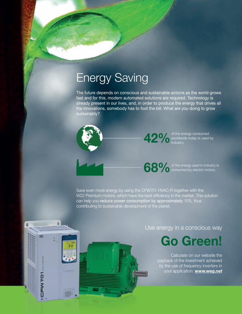
The future depends on conscious and sustainable actions as the world grows fast and for this, modern automated solutions are required. Technology is already present in our lives, and, in order to produce the energy that drives all the innovations, somebody has to foot the bill. What are you doing to grow sustainably?
Save even more energy by using the CFW701 HVAC-R together with the W22 Premium motors, which have the best efficiency in the market. This solution can help you reduce power consumption by approximately 15%, thus contributing to sustainable development of the planet.
of the energy used in industry is consumed by electric motors.68%
of the energy consumed worldwide today is used by industry.42%
Calculate on our website the payback of the investment achieved by the use of frequency inverters in
your application: www.weg.net
Use energy in a conscious way
Go Green!
Energy Saving
www.weg.net
CFW701 HVAC-R6
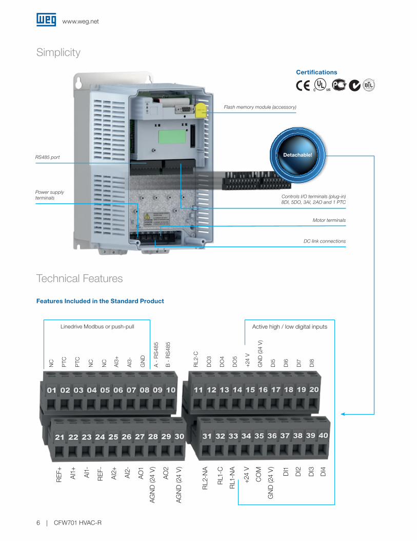
Simplicity
Certifications
Technical Features
Features Included in the Standard Product
DC link connections
Power supply terminals
Motor terminals
Controls I/O terminals (plug-in)8DI, 5DO, 3AI, 2AO and 1 PTC
RS485 port
B A C n e t
B L®
TE
ST
IN
G
L A B O R AT
OR
IE
S
Linedrive Modbus or push-pull Active high / low digital inputs
NC
PTC
PTC
NC
NC
AI3
+
AI3
-
GN
D
A -
RS
485
B -
RS
485
RL2
-C
DO
3
DO
4
DO
5
+24
V
GN
D (2
4 V
)
DI5
DI6
DI7
DI8
REF
+
AI1
+
AI1
-
REF
-
AI2
+
AI2
-
AO
1
AG
ND
(24
V)
AG
ND
(24
V)
RL2
-NA
RL1
-C
RL1
-NA
+24
V
CO
M
GN
D (2
4 V
)
DI1
DI2
DI3
DI4
AO
2
Detachable!
Flash memory module (accessory)
www.weg.net
CFW701 HVAC-R 7
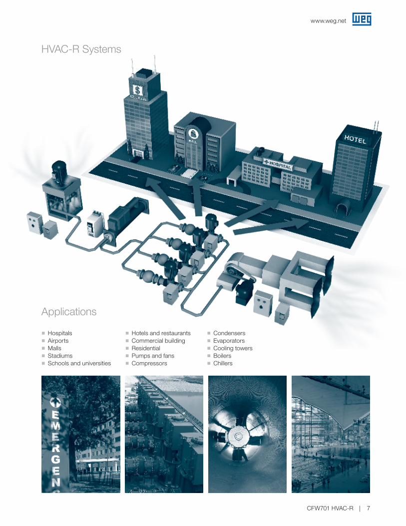
HVAC-R Systems
Applications
g Hospitals g Airports g Malls g Stadiums g Schools and universities
g Hotels and restaurants g Commercial building g Residential g Pumps and fans g Compressors
g Condensers g Evaporators g Cooling towers g Boilers g Chillers

www.weg.net
CFW701 HVAC-R8
Product and series
Drive identification Braking option
Protection class
RFI emmision
levelSafety stop
External control voltage
Hardware revision
Software versionFrame Rated current Supply phases Rated voltage
CFW701 A 03P6 T 4 NB N1 C31)2) Y1 W1 - - - - - -
CFW701
Check table belowNB = without dynamic brakingDB = with dynamic braking20 = IP2021 = IP21 (not available for frame size E)N1 = NEMA1Blank = with no RFI filterC3 = meets category 3 of IEC 61800-3 standard, with internal RFI flterBlank = without STO (Safe Torque Off) functionY1 = with STO (Safe Torque Off) function, meets EN 954-1/ISO 13849-1, category 3Blank = without 24 V dc power supplyW1 = with 24 V dc power supplyBlank = standardHx = special hardawareBlank = standardSx = special software
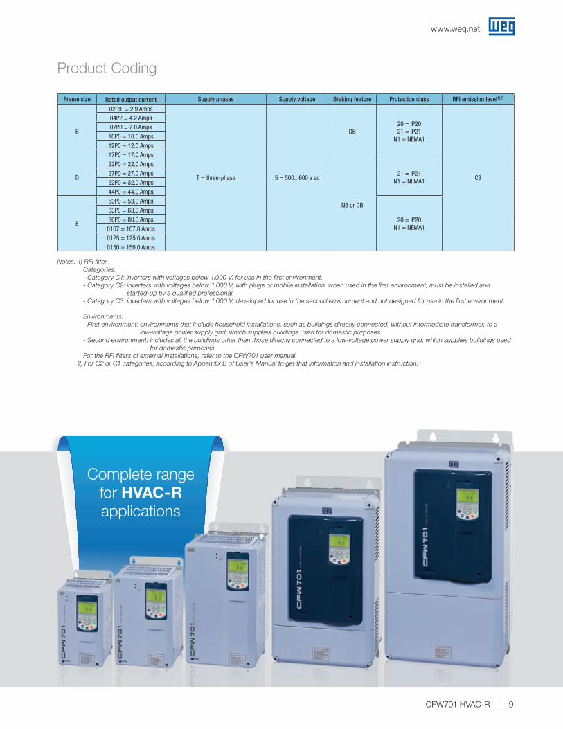
Product Coding
The CFW701 code identifies its construction characteristics, nominal current, voltage range and options. Using the product code, you may select the CFW701 required for your application simply and quickly.
Frame size Rated output current Supply phases Supply voltage Braking feature Protection class RFI emission level1)2)
A
06P0 = 6.0 Amps
S = single-phase 2 = 200...240 V ac DB20 = IP2021 = IP21
N1 = NEMA1
C3
07P0 = 7.0 Amps
10P0 = 10.0 Amps
A
07P0 = 7.0 Amps
T = three-phase 2 = 200...240 V ac
DB
20 = IP2021 = IP21
N1 = NEMA1
10P0 = 10.0 Amps
13P0 = 13.0 Amps
16P0 = 16.0 Amps
B
24P0 = 24.0 Amps
28P0 = 28.0 Amps
33P5 = 33.5 Amps
C
45P0 = 45.0 Amps
54P0 = 54.0 Amps
70P0 = 70.0 Amps
D86P0 = 86.0 Amps 21 = IP21
N1 = NEMA10105 = 105.0 Amps
E
0142 = 142.0 Amps
NB or DB20 = IP20
N1 = NEMA10180 = 180.0 Amps
0211 = 211.0 Amps
A
03P6 = 3.6 Amps
T = three-phase 4 = 380...480 V ac
DB
20 = IP2021 = IP21
N1 = NEMA1
05P0 = 5.0 Amps
07P0 = 7.0 Amps
10P0 = 10.0 Amps
13P5 = 13.5 Amps
B
17P0 = 17.0 Amps
24P0 = 24.0 Amps
31P0 = 31.0 Amps
C
38P0 = 38.0 Amps
45P0 = 45.0 Amps
58P5 = 58.0 Amps
D70P5 = 70.0 Amps 21 = IP21
N1 = NEMA188P0 = 88.0 Amps
E
0105 = 105.0 Amps
NB or DB20 = IP20
N1 = NEMA10142 = 142.0 Amps
0180 = 180.0 Amps
0211 = 211.0 Amps
www.weg.net
CFW701 HVAC-R 9
Product Coding
Notes: 1) RFI filter.Categories:- Category C1: inverters with voltages below 1,000 V, for use in the first environment.- Category C2: inverters with voltages below 1,000 V, with plugs or mobile installation, when used in the first environment, must be installed and
started-up by a qualified professional.- Category C3: inverters with voltages below 1,000 V, developed for use in the second environment and not designed for use in the first environment.
Environments:- First environment: environments that include household installations, such as buildings directly connected, without intermediate transformer, to a
low-voltage power supply grid, which supplies buildings used for domestic purposes.- Second environment: includes all the buildings other than those directly connected to a low-voltage power supply grid, which supplies buildings used
for domestic purposes.For the RFI filters of external installations, refer to the CFW701 user manual.
2) For C2 or C1 categories, according to Appendix B of User’s Manual to get that information and installation instruction.
Frame size Rated output current Supply phases Supply voltage Braking feature Protection class RFI emission level1)2)
B
02P9 = 2.9 Amps
T = three-phase 5 = 500...600 V ac
DB20 = IP2021 = IP21
N1 = NEMA1
C3
04P2 = 4.2 Amps07P0 = 7.0 Amps
10P0 = 10.0 Amps12P0 = 12.0 Amps17P0 = 17.0 Amps
D
22P0 = 22.0 Amps
NB or DB
21 = IP21 N1 = NEMA1
27P0 = 27.0 Amps32P0 = 32.0 Amps44P0 = 44.0 Amps
E
53P0 = 53.0 Amps
20 = IP20 N1 = NEMA1
63P0 = 63.0 Amps80P0 = 80.0 Amps0107 = 107.0 Amps0125 = 125.0 Amps0150 = 150.0 Amps
Complete range for HVAC-R applications
www.weg.net
CFW701 HVAC-R10
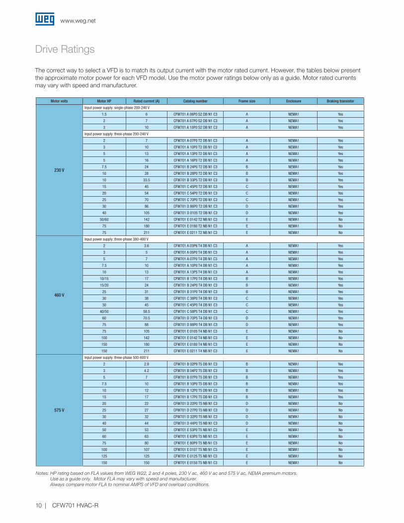
Motor volts Motor HP Rated current (A) Catalog number Frame size Enclosure Braking transistor
230 V
Input power supply: single-phase 200-240 V
1.5 6 CFW701 A 06P0 S2 DB N1 C3 A NEMA1 Yes
2 7 CFW701 A 07P0 S2 DB N1 C3 A NEMA1 Yes
3 10 CFW701 A 10P0 S2 DB N1 C3 A NEMA1 Yes
Input power supply: three-phase 200-240 V
2 7 CFW701 A 07P0 T2 DB N1 C3 A NEMA1 Yes
3 10 CFW701 A 10P0 T2 DB N1 C3 A NEMA1 Yes
5 13 CFW701 A 13P0 T2 DB N1 C3 A NEMA1 Yes
5 16 CFW701 A 16P0 T2 DB N1 C3 A NEMA1 Yes
7.5 24 CFW701 B 24P0 T2 DB N1 C3 B NEMA1 Yes
10 28 CFW701 B 28P0 T2 DB N1 C3 B NEMA1 Yes
10 33.5 CFW701 B 33P5 T2 DB N1 C3 B NEMA1 Yes
15 45 CFW701 C 45P0 T2 DB N1 C3 C NEMA1 Yes
20 54 CFW701 C 54P0 T2 DB N1 C3 C NEMA1 Yes
25 70 CFW701 C 70P0 T2 DB N1 C3 C NEMA1 Yes
30 86 CFW701 D 86P0 T2 DB N1 C3 D NEMA1 Yes
40 105 CFW701 D 0105 T2 DB N1 C3 D NEMA1 Yes
50/60 142 CFW701 E 0142 T2 NB N1 C3 E NEMA1 No
75 180 CFW701 E 0180 T2 NB N1 C3 E NEMA1 No
75 211 CFW701 E 0211 T2 NB N1 C3 E NEMA1 No
460 V
Input power supply: three-phase 380-480 V
2 3.6 CFW701 A 03P6 T4 DB N1 C3 A NEMA1 Yes
3 5 CFW701 A 05P0 T4 DB N1 C3 A NEMA1 Yes
5 7 CFW701 A 07P0 T4 DB N1 C3 A NEMA1 Yes
7.5 10 CFW701 A 10P0 T4 DB N1 C3 A NEMA1 Yes
10 13 CFW701 A 13P5 T4 DB N1 C3 A NEMA1 Yes
10/15 17 CFW701 B 17P0 T4 DB N1 C3 B NEMA1 Yes
15/20 24 CFW701 B 24P0 T4 DB N1 C3 B NEMA1 Yes
25 31 CFW701 B 31P0 T4 DB N1 C3 B NEMA1 Yes
30 38 CFW701 C 38P0 T4 DB N1 C3 C NEMA1 Yes
30 45 CFW701 C 45P0 T4 DB N1 C3 C NEMA1 Yes
40/50 58.5 CFW701 C 58P5 T4 DB N1 C3 C NEMA1 Yes
60 70.5 CFW701 D 70P5 T4 DB N1 C3 D NEMA1 Yes
75 88 CFW701 D 88P0 T4 DB N1 C3 D NEMA1 Yes
75 105 CFW701 E 0105 T4 NB N1 C3 E NEMA1 No
100 142 CFW701 E 0142 T4 NB N1 C3 E NEMA1 No
150 180 CFW701 E 0180 T4 NB N1 C3 E NEMA1 No
150 211 CFW701 E 0211 T4 NB N1 C3 E NEMA1 No
575 V
Input power supply: three-phase 500-600 V
2 2.9 CFW701 B 02P9 T5 DB N1 C3 B NEMA1 Yes
3 4.2 CFW701 B 04P2 T5 DB N1 C3 B NEMA1 Yes
5 7 CFW701 B 07P0 T5 DB N1 C3 B NEMA1 Yes
7.5 10 CFW701 B 10P0 T5 DB N1 C3 B NEMA1 Yes
10 12 CFW701 B 12P0 T5 DB N1 C3 B NEMA1 Yes
15 17 CFW701 B 17P0 T5 DB N1 C3 B NEMA1 Yes
20 22 CFW701 D 22P0 T5 NB N1 C3 D NEMA1 No
25 27 CFW701 D 27P0 T5 NB N1 C3 D NEMA1 No
30 32 CFW701 D 32P0 T5 NB N1 C3 D NEMA1 No
40 44 CFW701 D 44P0 T5 NB N1 C3 D NEMA1 No
50 53 CFW701 E 53P0 T5 NB N1 C3 E NEMA1 No
60 63 CFW701 E 63P0 T5 NB N1 C3 E NEMA1 No
75 80 CFW701 E 80P0 T5 NB N1 C3 E NEMA1 No
100 107 CFW701 E 0107 T5 NB N1 C3 E NEMA1 No
125 125 CFW701 E 0125 T5 NB N1 C3 E NEMA1 No
150 150 CFW701 E 0150 T5 NB N1 C3 E NEMA1 No
Notes: HP rating based on FLA values from WEG W22, 2 and 4 poles, 230 V ac, 460 V ac and 575 V ac, NEMA premium motors. Use as a guide only. Motor FLA may vary with speed and manufacturer. Always compare motor FLA to nominal AMPS of VFD and overload conditions.
Drive Ratings
The correct way to select a VFD is to match its output current with the motor rated current. However, the tables below present the approximate motor power for each VFD model. Use the motor power ratings below only as a guide. Motor rated currents may vary with speed and manufacturer.

www.weg.net
CFW701 HVAC-R 11
Accessories and Optional
Option Type1) DescriptionOptional
item code2) Accessory code Available
Braking IGBT Optional
Used in high-inertia applications for the fast stop of the motor by means of an external braking resistance.
Resistance not included. For the calculation of the braking resistance, refer to the CFW701 user manual
DB -Factory
installation only
Degree of protection Accessory
For an IP20 product according to IEC standards. This version does not come with a KIP21X or KN1X
kit inside the product box203) -
User installation3)
For a IP21 product according to IEC standards. This version comes with a KIP21X kit inside the product box but
not installed on the CFW701214)
KIP21A-01 (frame size A)KIP21B-01 (frame size B)KIP21C-01 (frame size C)KIP21D-01 (frame size D)
User installation4)
For a NEMA 1 product according to NEMA standards. This product comes with a KN1X kit inside the product
box but not installed on the CFW701 N15)
KN1A-02 (frame size A) KN1B-02 (frame size B) KN1C-02 (frame size C)
KN1E-01 (frame size D - 105 A and 142 A) KN1E-02 (frame size D - 180 A and 211 A)
User installation5)
Safety stop OptionalAfter the activation of the safety stop function, the PWM
pulses in the output of the drive are blocked. It is according to ISO 13849-1 and EN 954-1 / category 3
Y1 -Factory
installation only
24 V dc external power supply for feeding control circuit
OptionalIt is a board on the power circuit containing a DC converter with a 24 V dc input and outputs suitable to supply voltage
to the control circuit of CFW701W1 -
Factory installation only
Flash memory module AccessoryUsed to download the programming of a CFW701
to others (copy function)- MMF-02
User installation
Mounting frame for remote keypad
AccessoryUsed to transfer the operation to the panel door or machine
console. Maximum distance of 10 m. Degree of protection IP56
- RHMIF-03User
installation
Cables for remote keypad AccessoryUsed to connect the CFW701 to the remote keypad
(CAB-RS-XM)-
CAB-RS-XM, where cables with lengths (X) of 1, 2, 3, 5, 7.5 and 10 meters
User installation
The CFW701 VFD was developed to meet the hardware configurations required by a wide range of applications. The table below presents the available options:
Notes: 1) Optional = hardware resources added to the CFW701 in the manufacturing process. Accessory = hardware resource requested as a separated item. 2) Request the product according to the Product Coding table. 3) If you have N1 or 21 version, the VFD can be used as IP20 without installing the KIP21X and/or KN1X kit.
4) Frame size E it is IP21 as standard without KIP21X kit.5) Frame size D it is NEMA1 as standard without KN1X kit.
Dimensions and Weights
Frame size IP20 Height in. (mm) Width in. (mm) Depth in. (mm) Weight lbs. (kg)
A 9.73 (247) 5.71 (145) 8.94 (227) 13.9 (6.3)
B 11.53 (293) 7.46 (190) 8.94 (227) 22.9 (10.4)
C 14.88 (378) 8.67 (220) 11.52 (293) 45.2 (20.5)
D 19.84 (504) 11.81 (300) 12.00 (305) 71.8 (32.6)
E 24.4 (620) 13.2 (335) 14.1 (358) 143.3 (65.0)
Frame size NEMA1 Height in. (mm) Width in. (mm) Depth in. (mm) Weight lbs. (kg)
A 12.02 (305) 5.71 (145) 8.94 (227) 15.7 (7.1)
B 13.82 (351) 7.46 (190) 8.94 (227) 24.9 (11.3)
C 17.64 (448.1) 8.67 (220) 11.52 (293) 47.2 (21.4)
D 19.84 (504) 11.81 (300) 12.00 (305) 71.8 (32.6)
E 1) 13.2 (335) 14.1 (358) 2)
Notes: 1) 28.94 (735) = 0142 T2, 0105 T4, 0142 T4 and T5 models 32.63 (828.9) = 0180 T2/T4, 0211 T2/T4 2) 147.97 (67.12) = 0142 T2, 0105 T4, 0142 T4 and T5 models 152.78 (69.3) = 0180 T2/T4, 0211 T2/T4
D
D
W
W
H
H

www.weg.net
CFW701 HVAC-R12
Easy programming: ladder
Free Software
SuperDrive G2Software application for programming, control and monitoring of WEG VFD.
Trend Function g On-line graphic monitoring of parameters/variables g Possibility to export an image with the respective graph based upon the selected period
USB connection
Friendly environment
Free on www.weg.net
SoftPLC - Built-in on the Standard ProductFunctionalities of a PLC available as standard, allowing the creation of applications. The WLP software and the SoftPLC functionality are a smart and simple way to make your CFW701, motor and application work together.
Trace Function g On-line graphic monitoring of parameters/variables
g Configurable up to six channels
Speed referenceContacts and coils
Comparators and math functions
PIDUser block protected bypassword
Counters andtimers
Editable HVAC-R
functions!
Trend Function similar an
oscilloscope!
www.weg.net
CFW701 HVAC-R 13
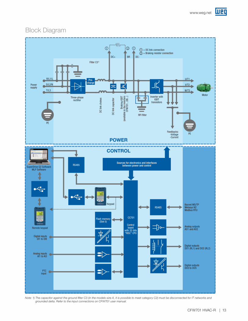
Block Diagram
Three-phaserectifier
Powersupply
T/L3
S/L2/N
R/L1/L
Filter C31)
DC+ BR DC-
= DC link connection= Braking resistor connection
1 1 12
2
PE
PE
Sources for electronics and interfacesbetween power and control
Remote keypad
Digital inputsDl1 to Dl8
Analog inputsAl1 to Al3
PTCinput
Flash memory(Slot 5)
RS485
RS485
Controlboard
with 32-bits"RISC" CPU
Analog outputsAO1 and AO2
Bacnet MS/TPMetasys N2Modbus RTU
Digital outputsDO1 (RL1) and DO2 (RL2)
Digital outputsDO3 to DO5
CC701
Keypad
RFI filter
Motor
U/T1
V/T2
W/T3
Inverter withIGBT
transistorsDC
link
cho
kes
DC li
nk c
apac
itor
Brak
ing
IGBT
(ava
ilabl
e in
the
inve
rters
CFW
701.
..DB.
..)
Feedbacks: -Voltage-Current
CONTROL
POWER
SuperDrive G2 SoftwareWLP Software
Pre-charge
Note: 1) The capacitor against the ground filter C3 (in the models size A, it is possible to meet category C2) must be disconnected for IT networks and grounded delta. Refer to the input connections on CFW701 user manual.

www.weg.net
CFW701 HVAC-R14
Technical Data
Power supplyVoltage and power range
1-phase, 200-240 V ac (+10% - 15%)1.5 to 3 HP (1.1 to 2.2 kW)
3-phase, 200-240 V ac (+10% - 15%)1.5 to 75 HP (1.1 to 55 kW)
3-phase, 380-480 V ac (+10% - 15%)2 to 150 HP (1.5 to 110 kW)
3-phase, 500-600 V ac (+10% - 15%)2 to 150 HP (1.5 to 110 kW)
Frequency 50...60 Hz (+/-2%_48 to 63 Hz)
Control
Displacement factor >0.98
Efficiency >97%
Power factor0.94 for three-phase input at nominal conditional0.70 for single-phase input at nominal conditional
Frequency range0 to 3.4 x motor rated frequency (0403). The rated frequency is programable up to 300 Hz (V/Hz) and 120 Hz (vector mode) Switching Frequency data must be observed for speed limits
Switching frequency
Standard: 5 kHz (A, B, C, D frames)
2.5 kHz for all models frame E 380-480 V
2.5 kHz for frame E models 142/180 Amps (ND) 200-240 V
2.5 kHz for frame E model 211 Amps (ND/HD) 200-240 V
Available options for 2.5/5/10 kHz (check for derating)
Overload capacity Normal duty (ND) 110% for 1min every 10min
Aceleration time 0 to 999s
Deceleration time 0 to 999s
Normal Duty (ND) 110% for 1min every 10min
Heavy Duty (HD) 150% for 1min every 10min
Environment
Temperature
-10 to 50 ºC (14 to 122 ºF) for most of models. For operating temperature of each model the table “dimentions, weight and temperature” shall be checked
-10...60 ºC for frames A, B, C and D (up to 45 ºC without derating for models 13 A and 24 A / 200...240 V, 7 and 10 A / 380...480 V and up to 50 ºC without derating for the other models) and -10...55 ºC for frame E (up to 45 ºC without derating). If derating has to be considered have 2% current reduction for each ºC above the specific operating temperature
Humidity 5 to 90% with no condensation
Altitude0 to 1,000 meters with no derating
Up to 4,000 meters with current reduction of 1% for each 100 meters above 1,000 meters
Braking methods
Dynamic brakingAvailable as standard for frame sizes A, B, C and D for 460 V and D for 660 V. For frame size E “DB” models has to be used.An extra resistor must be fitted in for dynamic braking capability
Optimal braking There is no need for braking resistor
DC braking DC current applied to motor
Performance
V/F
Speed control
Regulation: 1% of rated speed
Speed variation range 1:20
Voltage vector WWRegulation: 1% of rated speed
Speed variation range 1:30
I/Os
Inputs
Digital 8 x isolated bidirectional 24 V
Analog2 x +/-10 V, 11 bits + signal (differencial) or 0/4...20 mA, 11 bits (differencial)
Impedance: 400 kW for voltage signal / 500 W for current signal
Output
Relay2 x relay NO/NC contact (240 V ac/1 A)
4 x open drain (24 V/200 mA)
Analog1 x 0/4 - 20 mA 11 bits
2 x 0...10 V or 0/4...20 mA, 11 bits (not isolates from inverter ground)
24 V power supply capacity 500 mA (available for the user, including I/Os)
Communication
Modbus-RTUBACnet MS/TPMetasys N2
RS485 built-in (available in controlterminals)
RS485 built-in / SuperDrive and WLP software
USB built in SuperDrive and WLP software

www.weg.net
CFW701 HVAC-R 15
Technical Data - Standards
Safety standards
UL 508C Power conversion equipment
UL 840 Insulation coordination including clearances and creepage distances for electrical equipment
EN 61800-51 Safety requirements electrical thermal and energy
EN 50178 Electronic equipment for use in power installations
EN 60204-1Safety of machinery. Electrical equipment of machines. Part: General requirement Note: For a machine to comply with this standard, the manufacturer of the machine is responsible for installing an emergency stop device and a device for disconnection from the power line
EN 60146 (IEC) Semiconductor converters
EN 61800-2Adjustable speed electrical power drive systems - Part 2: General requirements - Ratings specifications for low voltage adjustable frequency AC power drive systems
Electromagnetic compatibility standards
EN 61800-3 Adjustable speed electrical power drive systems - Part 3: EMC product standard including specific test methods
EN 55011Limits and methods of measurement of radio disturbance characteristics of industrial, scientific and medical (ISM) radio-frequency equipment CISPR11 - Industrial, scientific and medical (ISM) radio-frequency equipment - Electromagnetic disturbance characteristics - Limits and methods of measurement
EN 61000-4-2 Electromagnetic Compatibility (EMC) - Part 4: Testing and measurement techniques - Section 2: Electrostatic discharge immunity test
EN 61000-4-3Electromagnetic compatibility (EMC) - Part 4: Testing and measurement techniques - Section 3: Radiated, radio-frequency, electromagnetic field immunity test
EN 61000-4-4Electromagnetic compatibility (EMC) - Part 4: Testing and measurement techniques - Section 4: Electrical fast transient/burst immunity test
EN 61000-4-5 Electromagnetic compatibility (EMC) - Part 4: Testing and measurement techniques - Section 5: Surge immunity test
EN 61000-4-6Electromagnetic compatibility (EMC) - Part 4: Testing and measurement techniques - Section 6: Immunity to conducted disturbances, inducted by radio-frequency fields
Mechanical construction standards
EN 60529 Degrees of protection provided by enclosures (IP code)
UL 50 Enclosures for electrical equipment

ARGENTINAWEG EQUIPAMIENTOSELECTRICOSSan Francisco - CordobaPhone: +54 3564 421 [email protected]/ar
WEG PINTURAS - PulverluxBuenos AiresPhone: +54 11 4299 [email protected]
AUSTRALIAWEG AUSTRALIA Victoria Phone: +61 3 9765 [email protected]/au
AUSTRIAWATT DRIVE - WEG GroupMarkt PiestingPhone: +43 2633 404 [email protected]
BELGIUMWEG BENELUXNivelles - BelgiumPhone: +32 67 88 84 [email protected]/be
BRAZILWEG EQUIPAMENTOS ELÉTRICOSJaraguá do Sul - Santa CatarinaPhone: +55 47 [email protected]/br
CHILEWEG CHILE SantiagoPhone: +56 2 784 [email protected]/cl
CHINAWEG NANTONG Nantong - JiangsuPhone: +86 0513 8598 [email protected]/cn
COLOMBIAWEG COLOMBIA BogotáPhone: +57 1 416 [email protected]/co
ECUADORWEG ECUADOR QuitoPhone: 5144 339/342/[email protected]/ec
FRANCEWEG FRANCESaint Quentin Fallavier - LyonPhone: +33 4 74 99 11 [email protected]/fr
GERMANYWEG GERMANY KerpenPhone: +49 2237 9291 [email protected]/de
WEG BALINGEN BalingenPhone: +49 7433 9041 [email protected]
GHANAZEST ELECTRIC GHANA - WEG Group AccraPhone: +233 30 27 664 [email protected]
INDIAWEG ELECTRIC INDIABangalore - KarnatakaPhone: +91 80 4128 [email protected]/in
WEG INDUSTRIES INDIA Hosur - Tamil NaduPhone: +91 4344 301 [email protected]/in
ITALYWEG ITALIACinisello Balsamo - MilanoPhone: +39 02 6129 [email protected]/it
JAPANWEG ELECTRIC MOTORSJAPANYokohama City - KanagawaPhone: +81 45 550 [email protected]/jp
MALAYSIAWATT EURO-DRIVE - WEG GroupShah Alam - SelangorPhone: 603 [email protected]
MEXICOWEG MEXICOHuehuetocaPhone: +52 55 5321 [email protected]/mx
VOLTRAN - WEG GroupTizayuca - HidalgoPhone: +52 77 5350 9354www.voltran.com.mx
NETHERLANDSWEG NETHERLANDS - Oldenzaal - OverijsselPhone: +31 541 571 [email protected]/nl
PERUWEG PERU LimaPhone: +51 1 209 [email protected]/pe
PORTUGALWEG EUROMaia - PortoPhone: +351 22 [email protected]/pt
RUSSIA and CISWEG ELECTRIC CIS Saint PetersburgPhone: +7 812 363 [email protected]/ru
SOUTH AFRICAZEST ELECTRIC MOTORSWEG Group JohannesburgPhone: +27 11 723 [email protected]
SPAINWEG IBERIA MadridPhone: +34 91 655 30 [email protected]/es
SINGAPOREWATT EURO-DRIVE - WEG Group SingaporePhone: +65 6 862 [email protected]
WEG SINGAPORE SingaporePhone: +65 [email protected]/sg
SCANDINAVIAWEG SCANDINAVIA Kungsbacka - SwedenPhone: +46 300 73 [email protected]/se
UKWEG ELECTRIC MOTORS U.K.Redditch - WorcestershirePhone: +44 1527 513 [email protected]/uk
UNITED ARAB EMIRATESWEG MIDDLE EAST DubaiPhone: +971 4 813 [email protected]/ae
USAWEG ELECTRICDuluth - GeorgiaPhone: +1 678 249 [email protected] www.weg.net/us
ELECTRIC MACHINERY - WEG Group Minneapolis - MinnesotaPhone: +1 612 378 8000www.electricmachinery.com
VENEZUELAWEG INDUSTRIAS VENEZUELA Valencia - CaraboboPhone: +58 241 821 [email protected]/ve
WEG Electric Corp. 6655 Sugarloaf Parkway Duluth, GA 30097 Phone: 1-800-ASK-4WEG www.weg.net C
od: U
SA
CFW
701.
1020
14.0
0 | R
ev: 0
0 | D
ate
(m/y
): 11
/201
4Th
e va
lues
sho
wn
are
sub
ject
to c
hang
e w
ithou
t prio
r no
tice.
WEG Worldwide Operations
For those countries where there is not a WEG own operation, find our local distributor at www.weg.net.