Embed Size (px)
Citation preview
Motors | Automation | Energy | Transmission & Distribution | Coatings
CFW11
Variable Speed Drives
www.weg.net
CFW11 - Variable Speed Drives2
Innovative and simple
The CFW11 presents many innovations that are helpful and beneficial to customers, mainly due to the simplicity of its installation and operation. The CFW11 was developed based on Plug-and-Play philosophy (connect and use) allowing simple and fast installation of the VSD and its accessories. The Keypad has a navigation and programming system similar to mobile phones, with soft-key buttons. It is possible to access the parameters sequentially or through groups of parameters. The Keypad also makes the Oriented Start-up function available, guiding the user through the necessary programming.
Flexibility
The CFW11 adapts to the customer’s needs through a broad range of accessories which are easily installed. Besides this, the standard product comes with a small PLC called Soft PLC that offers PLC functionalities and it allows the costumer for creation of his/her own user applications through the WLP software (programming in LADDER).
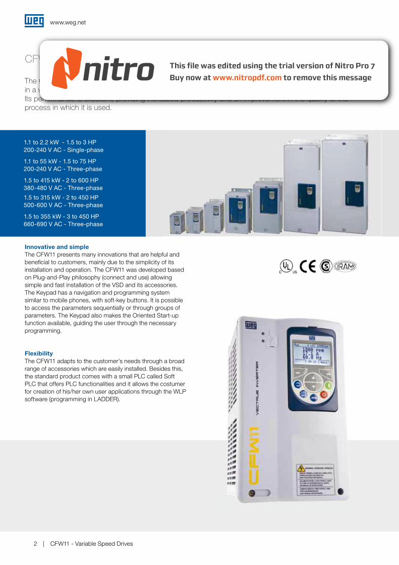
CFW11
The CFW11 is a system drive designed for the control of squirel cage induction motors. It can be used
in a wide range of applications, since it is designed for running on either Normal or Heavy Duty loads.
Its performance is excellent, providing increased productivity and an improvement in the quality of the
process in which it is used.
1.1 to 2.2 kW - 1.5 to 3 HP
200-240 V AC - Single-phase
1.1 to 55 kW - 1.5 to 75 HP
200-240 V AC - Three-phase
1.5 to 415 kW - 2 to 600 HP
380-480 V AC - Three-phase
1.5 to 315 kW - 2 to 450 HP
500-600 V AC - Three-phase
1.5 to 355 kW - 3 to 450 HP
660-690 V AC - Three-phase
www.weg.net
CFW11 - Variable Speed Drives 3
Technology - Patents
Vectrue Technology®
WEG VARIABLE SPEED DRIVE CONTROL TECHNOLOGY Linear and adjustable V/f, VVW (Voltage Vector WEG) and vector control are available in the same product. Two types of vector control: Sensorless and closed loop Vector control (Encoder Interface required). Sensorless vector control permits high torque and quick response in open loop, even at low speeds. The self-tuning function automatically matches the vector control or VVW to the motor and load used. Through the adjustable V/f control, it is possible, for example, to adjust a quadratic V/f curve, providing energy savings for quadratic torque loads (e.g.: centrifugal pumps and fans).
Optimal Braking®
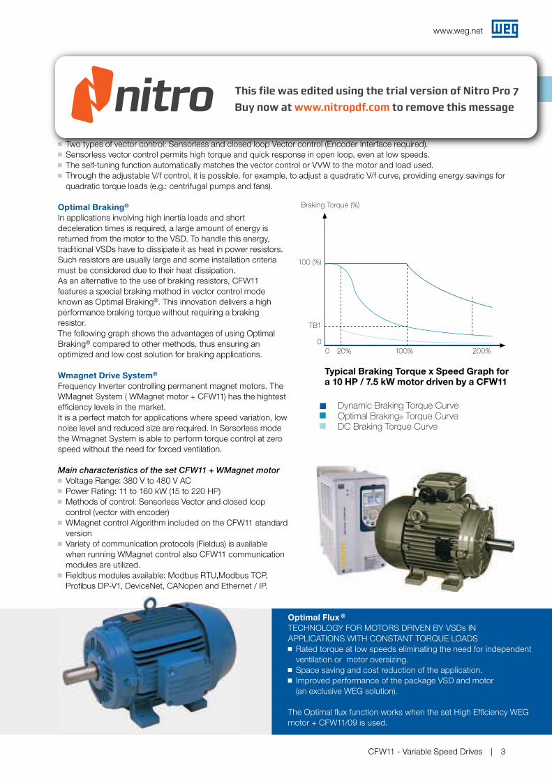
In applications involving high inertia loads and short deceleration times is required, a large amount of energy is returned from the motor to the VSD. To handle this energy, traditional VSDs have to dissipate it as heat in power resistors. Such resistors are usually large and some installation criteria must be considered due to their heat dissipation. As an alternative to the use of braking resistors, CFW11 features a special braking method in vector control mode known as Optimal Braking®. This innovation delivers a high performance braking torque without requiring a braking resistor.The following graph shows the advantages of using Optimal Braking® compared to other methods, thus ensuring an optimized and low cost solution for braking applications.
Typical Braking Torque x Speed Graph for a 10 HP / 7.5 kW motor driven by a CFW11
Dynamic Braking Torque CurveOptimal Braking® Torque CurveDC Braking Torque Curve
Braking Torque (%)
100 (%)
TB1
0
0 20% 100% 200%
Optimal Flux ®
TECHNOLOGY FOR MOTORS DRIVEN BY VSDs IN APPLICATIONS WITH CONSTANT TORQUE LOADS Rated torque at low speeds eliminating the need for independent ventilation or motor oversizing.
Space saving and cost reduction of the application. Improved performance of the package VSD and motor
(an exclusive WEG solution).
The Optimal flux function works when the set High Efficiency WEG motor + CFW11/09 is used.
Wmagnet Drive System®
Frequency Inverter controlling permanent magnet motors. The WMagnet System ( WMagnet motor + CFW11) has the hightest efficiency levels in the market. It is a perfect match for applications where speed variation, low noise level and reduced size are required. In Sersorless mode the Wmagnet System is able to perform torque control at zero speed without the need for forced ventilation.
Main characteristics of the set CFW11 + WMagnet motor
Voltage Range: 380 V to 480 V AC Power Rating: 11 to 160 kW (15 to 220 HP) Methods of control: Sensorless Vector and closed loop control (vector with encoder)
WMagnet control Algorithm included on the CFW11 standard version
Variety of communication protocols (Fieldus) is available when running WMagnet control also CFW11 communication modules are utilized.
Fieldbus modules available: Modbus RTU,Modbus TCP, Profibus DP-V1, DeviceNet, CANopen and Ethernet / IP.
www.weg.net
CFW11 - Variable Speed Drives4
Applications
Multi-Pump Control
The CFW11 features the Multipump Control, which permits the CFW11 to control up to 5 pumps in order to keep constant pressure regardless of the flow fluctuations. In this system, an intelligent algorithm control of pumps provided by means of a user application developed to run on CFW11 decides when to start or stop each pump based on the system demand. Besides that, the VSD also monitors the suction pressure and the tank level.The CFW11 also alternates the pumps according to their operating time, thus ensuring an uniform wear and tear of motors and pumps.Two types of Multipump Control are available: fixed and floating controls. In fixed control, the VSD is able to control one of the pumps at variable speed and to start and stop another 4 pumps at fixed speed. In floating control, the VSD is able to control up to 4 pumps, all of them at variable speed.The Multipump Control for CFW11 is available as an user application for running on Soft PLC (see page 14) and can be downloaded from www.weg.net
The CFW11 can be used in both simple and sophisticated applications, due to its broad range of functions and easy configuration, installation and operation. The CFW11, through its Vectrue Inverter technology, presents excellent static and dynamic performance, precise torque and speed control, dynamic response, positioning precision, and high overload capacity. The CFW11 was also developed for applications where the decisive factor is safety, through several built-in protections and alarms as well as through the safety stop function in accordance with EN 954-1, category III.
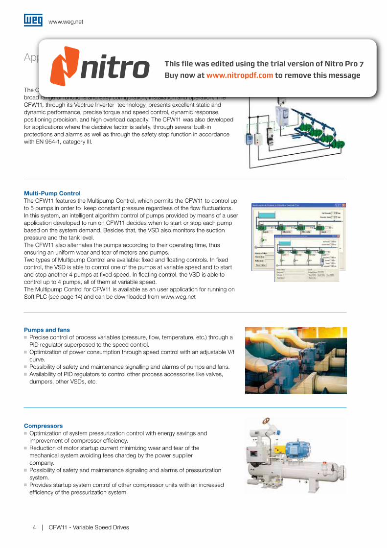
Pumps and fans
Precise control of process variables (pressure, flow, temperature, etc.) through a PID regulator superposed to the speed control.
Optimization of power consumption through speed control with an adjustable V/f curve.
Possibility of safety and maintenance signalling and alarms of pumps and fans.Availability of PID regulators to control other process accessories like valves,
dumpers, other VSDs, etc.
Compressors
Optimization of system pressurization control with energy savings and improvement of compressor efficiency. Reduction of motor startup current minimizing wear and tear of the
mechanical system avoiding fees chardeg by the power supplier company. Possibility of safety and maintenance signaling and alarms of pressurization
system. Provides startup system control of other compressor units with an increased
efficiency of the pressurization system.

www.weg.net
CFW11 - Variable Speed Drives 5
Applications
Paper and Cellulose / Wood
Three monitoring parameters displayed at once on the keypad. USB communication port at the front of the VSD for data monitoring and
parameters configuration via software Superdrive. Precise speed and torque control. Flexible hardware programming and configuration, making applications
where syncronism is required easier. Possibility to be integrated in a variety of communication protocols commonly
used in industry. Provided in a compact design the CFW11 Series allows the assembly
directly next to one another with no derating. Quick and simplified programming. Highly reliable and robust. For large power ratings modular topology can be used (CFW11M).
Chemical and Petrochemical
Highly reliable and robust. Provided in a compact design the CFW11 Series allows the assembly directly
next to one another with no derating. Plug-and-play system for additional modules, ensuring greater flexibility in
adapting to existing systems. Possibility to be integrated in a variety of communication protocols commonly
used in the industry.
Ironworks and Metallurgy
Highly precise speed and torque control. Large overload capacity (models sized in HD). Flexible hardware programming and configuration. Possibility to be integrated in a variety of communication protocols mainly used
in the industry. Provided in a compact design the CFW11 Series allows the assembly directly
next to one another with no derating. For large power ratings modular topology is used (CFW11M).
Cement and Mining
Robust and large overload capacity (models sized in HD). Provided in a compact design the CFW11 Series allows the assembly
directly next to one another with no derating. Possibility to be integrated in a variety of communication protocols commonly
used in industry. Quick and simplified programming. Highly reliable and robust. For large power ratings modular topology is used (CFW11M)
www.weg.net
CFW11 - Variable Speed Drives6
Applications
OverHead Cranes / Lifting
SoftPLC function. Three modes of vector control. Highly compact. Intelligent control of ventilation system.
Cooling
SoftPLC function built in the standard product enabling the use of two controllers simultaneously. This characteristic is for HVAC applications. Three monitoring parameters displayed at once on the keypad. USB communication port at the front of the VSD for data
monitoring and parameters configuration via software Superdrive.
Process Machines
Built-in PLC and Real Time Clock. Easiness and flexibility for connecting
to the most used fieldbus network. Fieldbus. Precise speed and torque in all speed ranges. User friendly interface and programming.
Sugar and Alcohol
Modular and compact. 12-pulse rectifier for reduction of harmonic content. Regenerative rectifier for centrifuges. Highly robust and reliable.
www.weg.net
CFW11 - Variable Speed Drives 7
Keypad
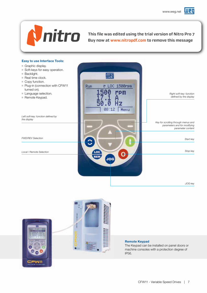
The CFW11 keypad was developed for simple and fast interaction while providing excellent visibility for the user.
Easy to use Interface Tools:
Graphic display. Soft-keys for easy operation. Backlight. Real time clock. Copy function. Plug-in (connection with CFW11
turned on). Language selection. Remote Keypad.
Left soft-key: function defined by
the display
Right soft-key: function
defined by the display
Key for scrolling through menus and
parameters and for modifying
parameter content
FWD/REV Selection
Local / Remote Selection
JOG key
Start key
Stop key
Remote Keypad
The Keypad can be installed on panel doors or machine consoles with a protection degree of IP56.
www.weg.net
CFW11 - Variable Speed Drives8
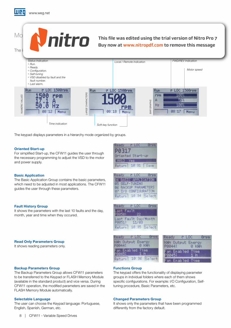
NUMERIC VALUES
Monitoring Modes
The keypad can be configured to display reading parameters in three different modes.
Oriented Start-up
For simplified Start-up, the CFW11 guides the user through the necessary programming to adjust the VSD to the motor and power supply.
Fault History Group
It shows the parameters with the last 10 faults and the day, month, year and time when they occured.
Read Only Parameters Group
It shows reading parameters only.
Basic Application
The Basic Application Group contains the basic parameters, which need to be adjusted in most applications. The CFW11 guides the user through these parameters.
Backup Parameters Group
The Backup Parameters Group allows CFW11 parameters to be transferred to the Keypad or FLASH Memory Module (available in the standard product) and vice versa. During CFW11 operation, the modified parameters are saved in the FLASH Memory Module automatically.
Selectable Language
The user can choose the Keypad language: Portuguese, English, Spanish, German, etc.
Changed Parameters Group
It shows only the parameters that have been programmed differently from the factory default.
Functions Group
The keypad offers the functionality of displaying parameter groups in indvidual folders where each of them shows specific configurations. For example: I/O Configuration, Self-tuning procedure, Basic Parameters, etc.
Status Indication
Run. Ready. Configuration. Self-tuning VSD disabled by fault and the fault number.
Last alarm.
Local / Remote Indication FWD/REV Indication
Motor speed
Time indication Soft-key function
LARGE CHARACTERS
BAR G
RAPHS
The keypad displays parameters in a hierarchy mode organized by groups.
www.weg.net
CFW11 - Variable Speed Drives 9
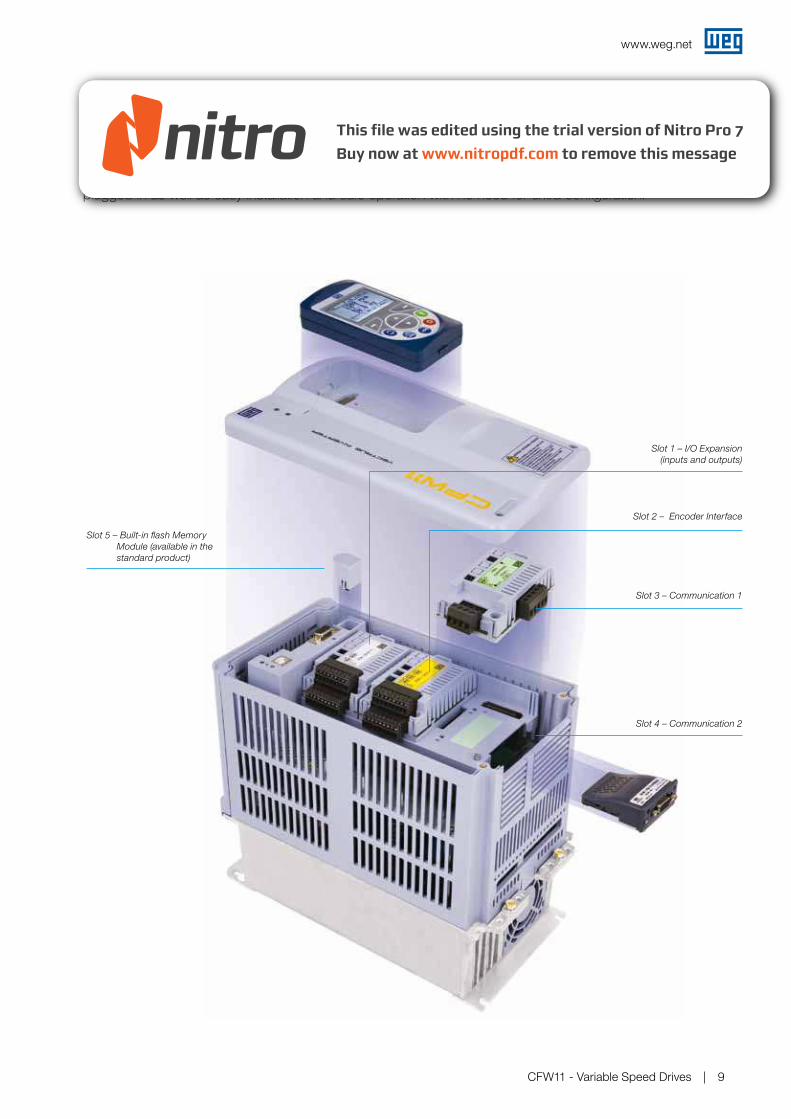
Accessories
The CFW11 was developed based on Plug and Play philosophy identifying automatically accessories
plugged in as well as easy installation and safe operation with no need for extra configuration.
Slot 5 – Built-in flash Memory
Module (available in the
standard product)
Slot 1 – I/O Expansion
(inputs and outputs)
Slot 2 – Encoder Interface
Slot 3 – Communication 1
Slot 4 – Communication 2
www.weg.net
CFW11 - Variable Speed Drives10
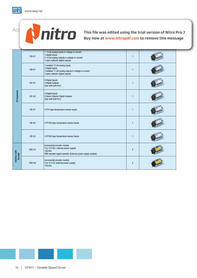
Name Description Slot Appearance
I/O Expansion
IOA-01
1 14-bit analog inputs in voltage or current
2 digital inputs
2 14-bit analog outputs in voltage or current
2 open collector digital outputs
1
IOB-01
2 isolated 12-bit analog inputs
2 digital inputs
2 isolated 11-bit analog outputs in voltage or current
2 open collector digital outputs
1
IOC-01
8 Digital Inputs
4 Digital Outputs
(Use with Soft PLC)
1
IOC-02
8 Digital Inputs
8 Open Collector Digital Outputs
(Use with Soft PLC)
1
IOE-01 5 PTC type temperature sensor Inputs 1
IOE-02 5 PT100 type temperature sensor Inputs 1
IOE-03 5 KTY84 type temperature sensor Inputs 1
Interface with
Encoder
ENC-01
Incremental encoder module
5 to 12 V DC ( internal power supply)
100 kHz
With encoder signal repeater (External power supply needed)
2
ENC-02
Incremental encoder module
5 to 12 V DC (internal power supply)
100 kHz
2
Accessories
www.weg.net
CFW11 - Variable Speed Drives 11
Accessories
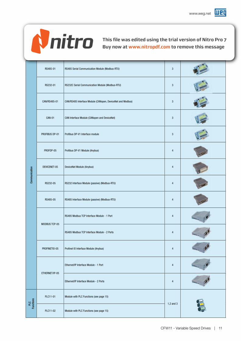
Name Description Slot Appearance
Com
munication
RS485-01 RS485 Serial Communication Module (Modbus-RTU) 3
RS232-01 RS232C Serial Communication Module (Modbus-RTU) 3
CAN/RS485-01 CAN/RS485 Interface Module (CANopen, DeviceNet and Modbus) 3
CAN-01 CAN Interface Module (CANopen and DeviceNet) 3
PROFIBUS DP-01 Profibus DP-V1 Interface module 3
PROFDP-05 Profibus DP-V1 Module (Anybus) 4
DEVICENET-05 DeviceNet Module (Anybus) 4
RS232-05 RS232 Interface Module (passive) (Modbus-RTU) 4
RS485-05 RS485 Interface Module (passive) (Modbus-RTU) 4
MODBUS TCP-05
RS485 Modbus TCP Interface Module - 1 Port 4
RS485 Modbus TCP Interface Module - 2 Ports 4
PROFINETIO-05 Profinet IO Interface Module (Anybus) 4
ETHERNET/IP-05
Ethernet/IP Interface Module - 1 Port 4
Ethernet/IP Interface Module - 2 Ports 4
PLC
Functions
PLC11-01 Module with PLC Functions (see page 15)
1,2 and 3
PLC11-02 Module with PLC Functions (see page 15)
www.weg.net
CFW11 - Variable Speed Drives12
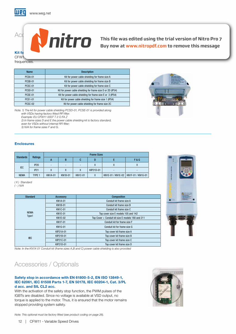
Kit for power cable shielding
CFW11 has a kit to simplify the connection of the motor cable shield to ground, providing a low-impedance connection for high frequencies.
Accessories
Note: 1) The kit for power cable shielding PCSD-01, PCSE-01 is provided along
with VSDs having factory fitted RFI filter.
Example: EU CFW11 0007 T 2 O FA Z
2) In frame sizes D and E the power cable shielding kit is factory standard,
even for VSDs without internal RFI filter;
3) N/A for frame sizes F and G.
Name Description
PCSA-01 Kit for power cable shielding for frame size A
PCSB-01 Kit for power cable shielding for frame size B
PCSC-01 Kit for power cable shielding for frame size C
PCSD-01 Kit for power cable shielding for frame size D or 2D (IP54)
PCSE-01 Kit for power cable shielding for frame size E or 3 (IP54)
PCS1-01 Kit for power cable shielding for frame size 1 (IP54)
PCSC-02 Kit for power cable shielding for frame size 2C
Enclosures
( X ) Standard
( - ) N/A
Note: In the KN1X-01 Conduit kit (frame sizes A,B and C) power cable shielding is also provided
Safety stop in accordance with EN 61800-5-2, EN ISO 13849-1,
IEC 62061, IEC 61508 Parts 1-7, EN 50178, IEC 60204-1, Cat. 3/PL
d acc. and SIL CL2 acc.
With the activation of the safety stop function, the PWM pulses of the IGBTs are disabled. Since no voltage is available at VSD output, no torque is applied to the motor. Thus, it is ensured that the motor remains stopped providing system safety.
Standards RatingsFrame Sizes
A B C D E F & G
IECIP20 - - - X X X
IP21 X X X KIP21D-01 - -
NEMA TYPE 1 KN1A-01 KN1B-01 KN1C-01 X KN1E-01 / KN1E-02 KN1F-01 / KN1G-01
Standard Accessory Composition
NEMA
Type1
KN1A-01 Conduit kit frame size A
KN1B-01 Conduit kit frame size B
KN1C-01 Conduit kit frame size C
KN1E-01 Top cover size E models 105 and 142
KN1E-02 Top Cover + Conduit kit size E models 180 and 211
KN1F-01 Conduit kit for frame size F
KN1G-01 Conduit kit for frame size G
IEC
KIP21A-01 Top cover kit frame size A
KIP21B-01 Top cover kit frame size B
KIP21C-01 Top cover kit frame size C
KIP21D-01 Top cover kit frame size D
Accessories / Optionals
Note: This optional must be factory fitted (see product coding on page 26).
www.weg.net
CFW11 - Variable Speed Drives 13
Accessories / Optionals
Remote keypad frame – RHMIF-01
Frame for Keypad installation on panel door or machine console. Degree of protection IP56.
Blank cover – HMID - 011
Blank cover to replace the standard VSD keypad when not used.
External control supply in 24 V DC¹
Used with communication networks (Profibus DP, DeviceNet, EtherNet/IP, etc.) so that the control circuit and the interface for the communication network continue working even if the AC supply is removed.
RFI suppressor filter1 (for the VSD to be in accordance
with EN 61800-3 and EN 55011)
CFW11 models with built-in RFI filter, when properly installed, meet the requirements of the electromagnetic compatibility directive – “EMC Directive 2004/108/EC”.Example: EU CFW11 0007 T 2 O FA Z For models from frame size A to D, the RFI filter is optional. But for models in frame size E, the RFI filter is included in the standard product.
1 This optionals must be factory fitted and orders must specify on the product coding (page 26) the desired option.
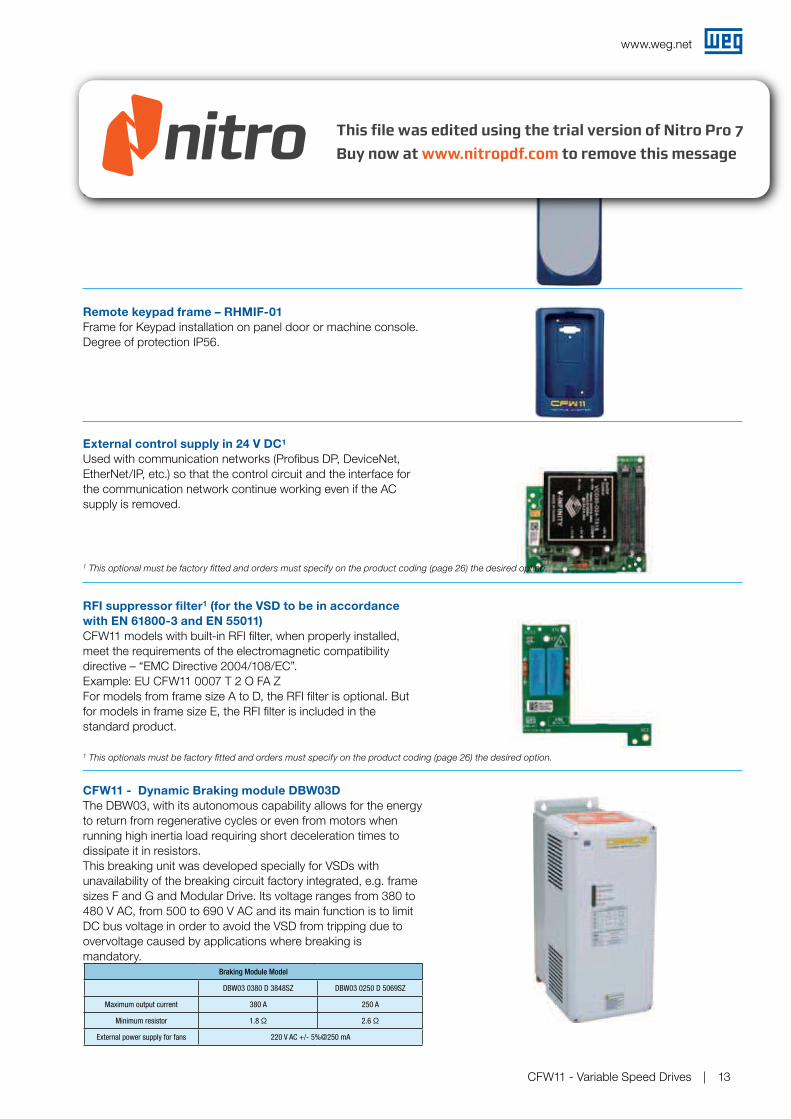
CFW11 - Dynamic Braking module DBW03D
The DBW03, with its autonomous capability allows for the energy to return from regenerative cycles or even from motors when running high inertia load requiring short deceleration times to dissipate it in resistors. This breaking unit was developed specially for VSDs with unavailability of the breaking circuit factory integrated, e.g. frame sizes F and G and Modular Drive. Its voltage ranges from 380 to 480 V AC, from 500 to 690 V AC and its main function is to limit DC bus voltage in order to avoid the VSD from tripping due to overvoltage caused by applications where breaking is mandatory.
1 This optional must be factory fitted and orders must specify on the product coding (page 26) the desired option.
Braking Module Model
DBW03 0380 D 3848SZ DBW03 0250 D 5069SZ
Maximum output current 380 A 250 A
Minimum resistor 1.8 Ω 2.6 Ω
External power supply for fans 220 V AC +/- 5%@250 mA
www.weg.net
CFW11 - Variable Speed Drives14
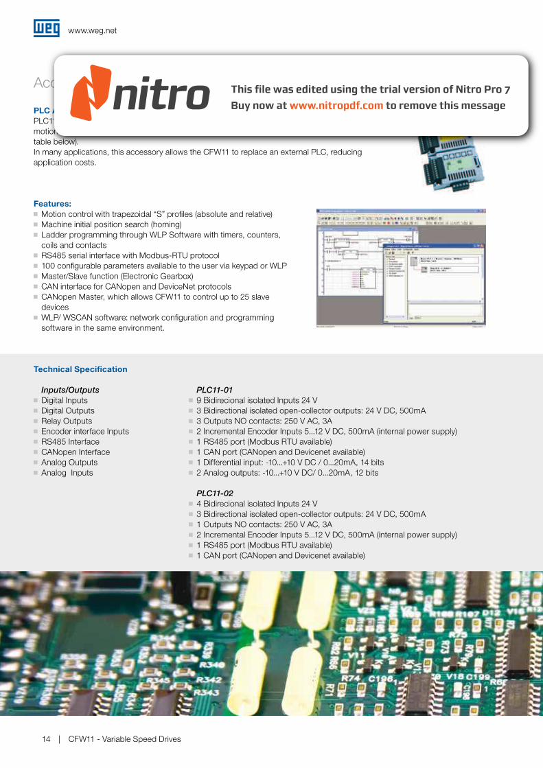
PLC Accessory - PLC11
PLC11 accessory provides the CFW11 with PLC functionality, speed reference generator and motion control functions. It comes in two options: PLC11-01 and PLC11-02 (see differences in the table below). In many applications, this accessory allows the CFW11 to replace an external PLC, reducing application costs.
Features:
Motion control with trapezoidal “S” profiles (absolute and relative) Machine initial position search (homing) Ladder programming through WLP Software with timers, counters,
coils and contacts RS485 serial interface with Modbus-RTU protocol 100 configurable parameters available to the user via keypad or WLP Master/Slave function (Electronic Gearbox) CAN interface for CANopen and DeviceNet protocols CANopen Master, which allows CFW11 to control up to 25 slave
devices WLP/ WSCAN software: network configuration and programming
software in the same environment.
Accessories
Technical Specification
Inputs/Outputs
Digital Inputs Digital Outputs Relay Outputs Encoder interface Inputs RS485 Interface CANopen Interface Analog Outputs Analog Inputs
PLC11-01
9 Bidirecional isolated Inputs 24 V 3 Bidirectional isolated open-collector outputs: 24 V DC, 500mA 3 Outputs NO contacts: 250 V AC, 3A 2 Incremental Encoder Inputs 5...12 V DC, 500mA (internal power supply) 1 RS485 port (Modbus RTU available) 1 CAN port (CANopen and Devicenet available) 1 Differential input: -10...+10 V DC / 0...20mA, 14 bits 2 Analog outputs: -10...+10 V DC/ 0...20mA, 12 bits
PLC11-02
4 Bidirecional isolated Inputs 24 V 3 Bidirectional isolated open-collector outputs: 24 V DC, 500mA 1 Outputs NO contacts: 250 V AC, 3A 2 Incremental Encoder Inputs 5...12 V DC, 500mA (internal power supply) 1 RS485 port (Modbus RTU available) 1 CAN port (CANopen and Devicenet available)
www.weg.net
CFW11 - Variable Speed Drives 15
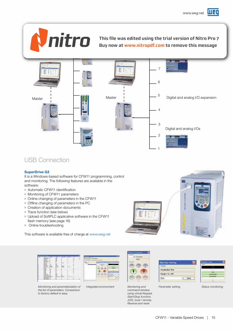
SuperDrive G2
It is a Windows-based software for CFW11 programming, control and monitoring. The following features are available in the software: Automatic CFW11 identification Monitoring of CFW11 parameters Online changing of parameters in the CFW11 Offline changing of parameters in the PC Creation of application documents Trace function (see below) Upload of SoftPLC applicative software in the CFW11
flash memory (see page 16) Online troubleshooting
This software is available free of charge at www.weg.net
USB Connection
Parameter settingIntegrated environment
Monitoring and
command window
using virtual Keypad.
Start/Stop function,
JOG, local / remote,
Reverse and reset
Status monitoringMonitoring and parameterization of
the list of parameters. Comparison
to factory default is easy.
Master
CANopen slave CANopen slave
Digital and analog I/O expansion
Digital and analog I/Os
Digital and analog I/Os
WLP / WSCAN Software
Example of use of PLC11-01 as CANopen network master
1
2
3
4
5
6
7
8WLP / WSCAN Software
Master
www.weg.net
CFW11 - Variable Speed Drives16
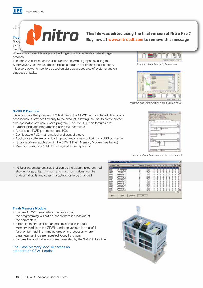
USB Connection
Trace Function
Trace function is used to register CFW11 variables (like current, voltage, speed, etc.) when a given event occurs in the system (eg.: alarm / fault, overload, overvoltage, etc.).When a given event takes place the trigger function activates data storage process. The stored variables can be visualized in the form of graphs by using the SuperDrive G2 software. Trace function simulates a 4-channel oscilloscope.It is a very powerful tool to be used on start-up procedures of systems and on diagoses of faults.
Trace function configuration in the SuperDrive G2
Example of graph visualization screen
SoftPLC Function
It is a resource that provides PLC features to the CFW11 without the addition of any accessories. It provides flexibility to the product, allowing the user to create his/her own applicative software (user’s program). The SoftPLC main features are: Ladder language programming using WLP software Access to all VSD parameters and I/Os Configurable PLC, mathematical and control blocks Applicative software download, upload and online monitoring via USB connection Storage of user application in the CFW11 Flash Memory Module (see below) Memory capacity of 15kB for storage of a user aplication
49 User parameter settings that can be individually programmed allowing tags, units, minimum and maximum values, number of decimal digits and other characteristics to be changed.
Simple and practical programming environment
Flash Memory Module
It stores CFW11 parameters. It ensures that the programming will not be lost as there is a backup of the parameters. It permits the transfer of parameters stored in the flash
Memory Module to the CFW11 and vice versa. It is an useful function for machine manufactures or in processes where parameter settings are repeated (Copy Function). It stores the applicative software generated by the SoftPLC function.
The Flash Memory Module comes as standard on CFW11 series.
www.weg.net
CFW11 - Variable Speed Drives 17
General Input
Rectifier Unit
Supply Network Single DC Link
CFW11
1 2 3 4
n
1 2
nnnn
2 3 4
Technical Features
Built-in DC link Reactor
Allows the VSD to be installed in any network (there is no minimum impedance restriction). Typical power factor (PF) for rated condition:0.94 for models with three-phase supply0.70 for models with single-phase 0,70 for
models with single-phase supply/three-phase supply = 0,94 Displacement Power factor > 0,98 Meets the 61000-3-12 standard, related
to low order current harmonics in the network
Single DC Busbar
Usually used in multi-motor systems, common DC bus confguration is a good solution for energy savings.In this confguration, individual VSD rectifer bridges are replaced with a common input rectifer unit.Each VSD is then directly fed from the DC bus to its DC link terminals.This solution allows the energy in the DC bus to be shared among the VSDs connected to it, thus optimizing the power consumption in the system.The standard CFW11 sizes A to E and special hardware version (DC) for frame sizes F and G can be connected to a DC bus system. (When required the factory should be consulted for further details)
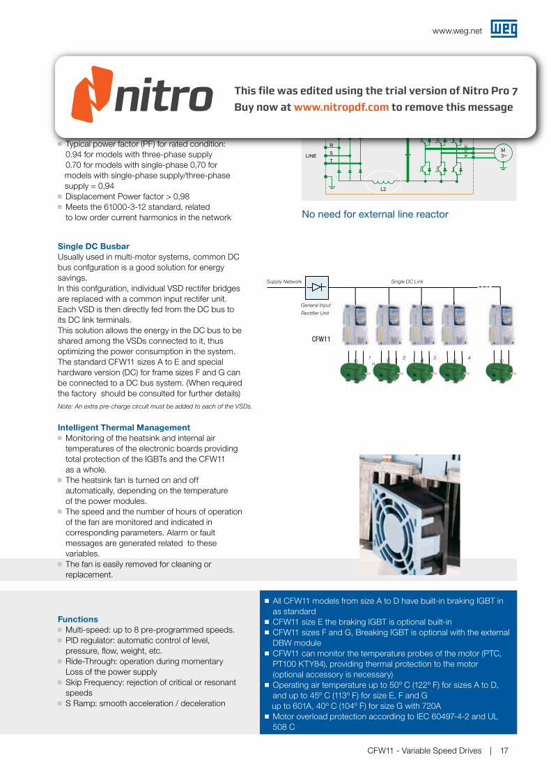
Intelligent Thermal Management
Monitoring of the heatsink and internal air temperatures of the electronic boards providing total protection of the IGBTs and the CFW11 as a whole. The heatsink fan is turned on and off
automatically, depending on the temperature of the power modules. The speed and the number of hours of operation
of the fan are monitored and indicated in corresponding parameters. Alarm or fault messages are generated related to these variables. The fan is easily removed for cleaning or
replacement.
All CFW11 models from size A to D have built-in braking IGBT in as standard
CFW11 size E the braking IGBT is optional built-inCFW11 sizes F and G, Breaking IGBT is optional with the external
DBW moduleCFW11 can monitor the temperature probes of the motor (PTC,
PT100 KTY84), providing thermal protection to the motor (optional accessory is necessary)
Operating air temperature up to 50º C (122º F) for sizes A to D, and up to 45º C (113º F) for size E, F and G up to 601A, 40º C (104º F) for size G with 720A Motor overload protection according to IEC 60497-4-2 and UL
508 C
Functions
Multi-speed: up to 8 pre-programmed speeds. PID regulator: automatic control of level,
pressure, flow, weight, etc. Ride-Through: operation during momentary
Loss of the power supply Skip Frequency: rejection of critical or resonant
speeds S Ramp: smooth acceleration / deceleration
No need for external line reactor
Note: An extra pre-charge circuit must be added to each of the VSDs.
www.weg.net
CFW11 - Variable Speed Drives18
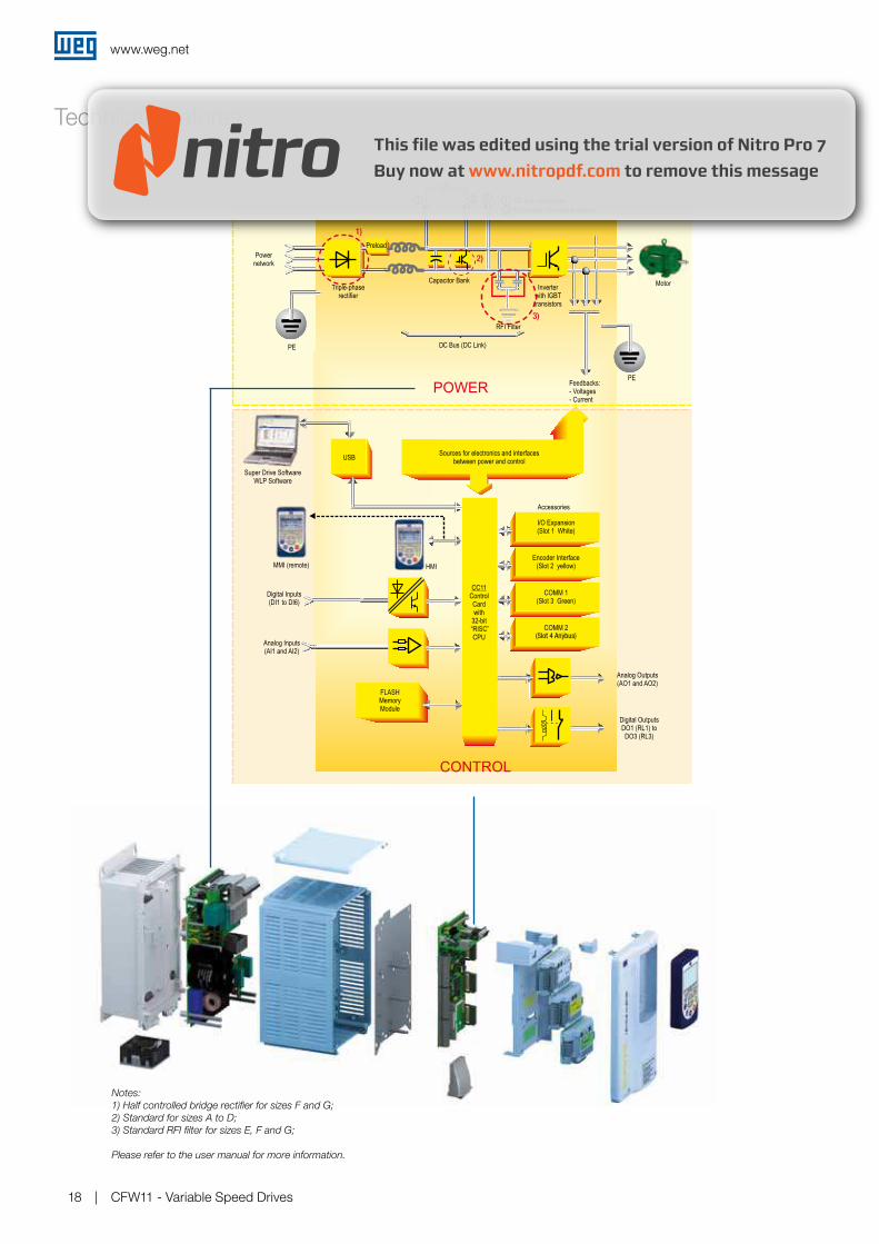
Technical Features
(Slot 4 Anybus)
1)
2)
3)
Notes:
1) Half controlled bridge rectifier for sizes F and G;
2) Standard for sizes A to D;
3) Standard RFI filter for sizes E, F and G;
Please refer to the user manual for more information.
www.weg.net
CFW11 - Variable Speed Drives 19
Drive Ratings
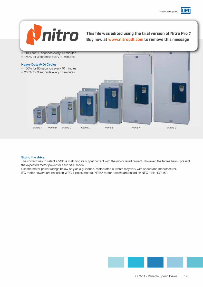
Normal Duty (ND) Cycle:
110% for 60 seconds every 10 minutes 150% for 3 seconds every 10 minutes
Heavy Duty (HD) Cycle:
150% for 60 seconds every 10 minutes 200% for 3 seconds every 10 minutes
Sizing the drive:
The correct way to select a VSD is matching its output current with the motor rated current. However, the tables below present the expected motor power for each VSD model.Use the motor power ratings below only as a guidance. Motor rated currents may vary with speed and manufacturer. IEC motor powers are based on WEG 4-poles motors, NEMA motor powers are based on NEC table 430-150.
rmal Duty (ND) Cycle:
0% for 60 seconds every 10 minutes0% for 3 seconds every 10 minutes
vy Duty (HD) Cycle:
0% for 60 seconds every 10 minutes200% for 3 seconds every 10 minutes
Frame DFrame CFrame BFrame A Frame E Frame F Frame G
www.weg.net
CFW11 - Variable Speed Drives20
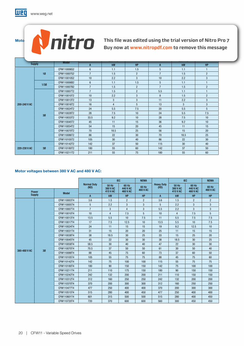
Motor voltages between 220 V AC and 230 V AC:
Motor voltages between 380 V AC and 480 V AC:
Normal Duty (ND)
IEC NEMA
Heavy Duty (HD)
IEC NEMA
50 Hz 220 V AC 230 V AC
60 Hz 230 V AC
50 Hz 220 V AC 230 V AC
60 Hz 230 V AC
Power Supply
ModelA kW HP A kW HP
200-240 V AC
1Ø
CFW110006S2 6 1.1 1.5 5 1.1 1
CFW110007S2 7 1.5 2 7 1.5 2
CFW110010S2 10 2.2 3 10 2.2 3
1/3ØCFW110006B2 6 1.1 1.5 5 1.1 1
CFW110007B2 7 1.5 2 7 1.5 2
3Ø
CFW110007T2 7 1.5 2 5.5 1.1 1
CFW110010T2 10 2.2 3 8 1.5 2
CFW110013T2 13 3 3 11 2.2 3
CFW110016T2 16 4 5 13 3 3
CFW110024T2 24 5.5 7.5 20 5.5 5
CFW110028T2 28 7.5 10 24 5.5 7.5
CFW110033T2 33.5 9.2 10 28 7.5 10
CFW110045T2 45 11 15 36 9.2 10
CFW110054T2 54 15 20 45 11 15
CFW110070T2 70 18.5 25 56 15 20
CFW110086T2 86 22 30 70 18.5 25
CFW110105T2 105 30 40 86 22 30
220-230 V AC 3Ø
CFW110142T2 142 37 50 115 30 40
CFW110180T2 180 55 60 142 37 50
CFW110211T2 211 55 75 180 55 60
Normal Duty (ND)
IEC NEMA
Heavy Duty (HD)
IEC NEMA
50 Hz 380 V AC 415 V AC
60 Hz 440 V AC 460 V AC
60 Hz 460 V AC
50 Hz 380 V AC 415 V AC
60 Hz 440 V AC 460 V AC
60 Hz 460 V AC
Power Supply
ModelA kW HP HP A kW HP HP
380-480 V AC 3Ø
CFW110003T4 3.6 1.5 2 2 3.6 1.5 2 2
CFW110005T4 5 2.2 3 3 5 2.2 3 3
CFW110007T4 7 3 4 3 5.5 2.2 3 3
CFW110010T4 10 4 7.5 5 10 4 7.5 5
CFW110013T4 13.5 5.5 10 7.5 11 5.5 7.5 7.5
CFW110017T4 17 7.5 12.5 10 13.5 5.5 10 7.5
CFW110024T4 24 11 15 15 19 9.2 12.5 10
CFW110031T4 31 15 20 20 25 11 15 15
CFW110038T4 38 18.5 30 25 33 15 25 20
CFW110045T4 45 22 30 30 38 18.5 30 25
CFW110058T4 58.5 30 40 40 47 22 30 30
CFW110070T4 70.5 37 50 50 61 30 50 40
CFW110088T4 88 45 75 60 73 37 60 50
CFW110105T4 105 55 75 75 88 45 75 60
CFW110142T4 142 75 100 100 115 55 75 75
CFW110180T4 180 90 150 150 142 75 100 100
CFW110211T4 211 110 175 150 180 90 150 150
CFW110242T4 242 132 200 200 211 110 150 150
CFW110312T4 312 160 250 250 242 132 200 200
CFW110370T4 370 200 300 300 312 160 250 250
CFW110477T4 477 250 400 400 370 200 300 300
CFW110515T4 515 280 400 450 477 250 400 400
CFW110601T4 601 315 500 500 515 280 400 450
CFW110720T4 720 370 600 600 560 300 450 450
www.weg.net
CFW11 - Variable Speed Drives 21
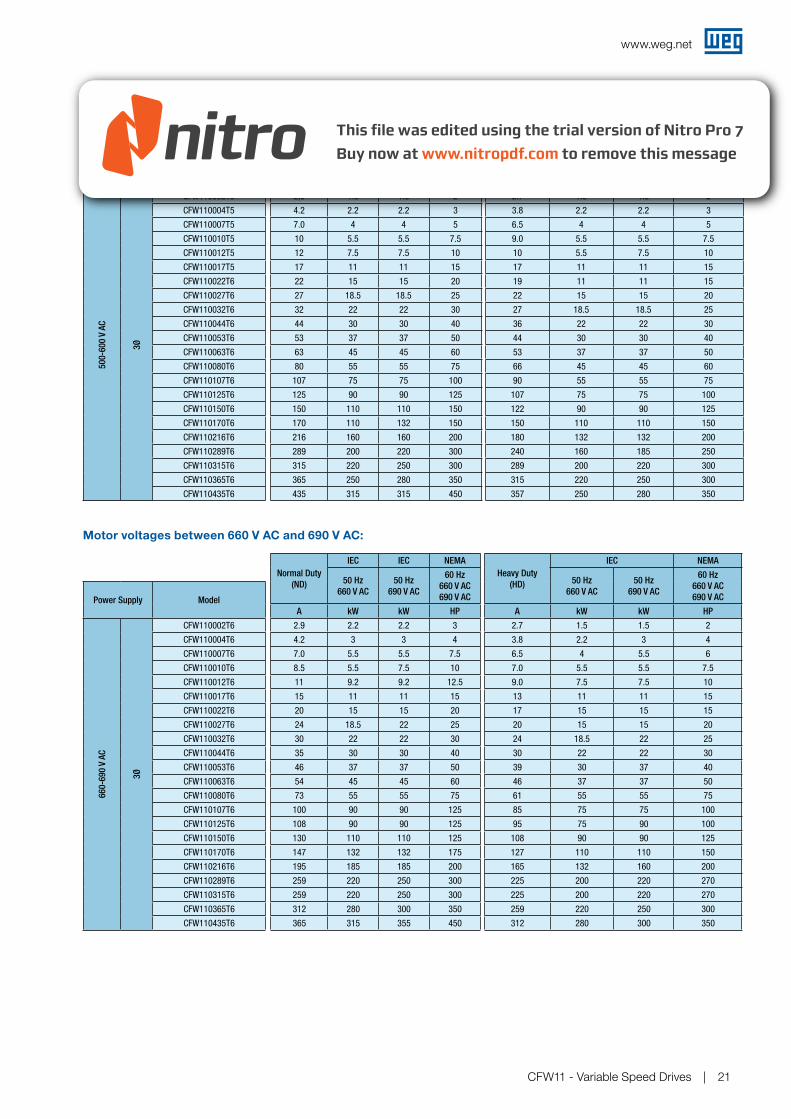
Motor voltages between 500 V AC and 600 V AC
Motor voltages between 660 V AC and 690 V AC:
Normal Duty
(ND)
IEC NEMAHeavy Duty
(HD)
IEC NEMA
50 Hz
525 V AC
50 Hz
575 V AC
60 Hz
575 V AC
50 Hz
525 V AC
50 Hz
575 V AC
60 Hz
575 V ACPower Supply Model
A kW kW HP A kW kW HP
500-600 V AC
3Ø
CFW110002T5 2,9 1.5 1.5 2 2.7 1.5 1.5 2
CFW110004T5 4.2 2.2 2.2 3 3.8 2.2 2.2 3
CFW110007T5 7.0 4 4 5 6.5 4 4 5
CFW110010T5 10 5.5 5.5 7.5 9.0 5.5 5.5 7.5
CFW110012T5 12 7.5 7.5 10 10 5.5 7.5 10
CFW110017T5 17 11 11 15 17 11 11 15
CFW110022T6 22 15 15 20 19 11 11 15
CFW110027T6 27 18.5 18.5 25 22 15 15 20
CFW110032T6 32 22 22 30 27 18.5 18.5 25
CFW110044T6 44 30 30 40 36 22 22 30
CFW110053T6 53 37 37 50 44 30 30 40
CFW110063T6 63 45 45 60 53 37 37 50
CFW110080T6 80 55 55 75 66 45 45 60
CFW110107T6 107 75 75 100 90 55 55 75
CFW110125T6 125 90 90 125 107 75 75 100
CFW110150T6 150 110 110 150 122 90 90 125
CFW110170T6 170 110 132 150 150 110 110 150
CFW110216T6 216 160 160 200 180 132 132 200
CFW110289T6 289 200 220 300 240 160 185 250
CFW110315T6 315 220 250 300 289 200 220 300
CFW110365T6 365 250 280 350 315 220 250 300
CFW110435T6 435 315 315 450 357 250 280 350
Normal Duty
(ND)
IEC IEC NEMA
Heavy Duty
(HD)
IEC NEMA
50 Hz
660 V AC
50 Hz
690 V AC
60 Hz
660 V AC
690 V AC
50 Hz
660 V AC
50 Hz
690 V AC
60 Hz
660 V AC
690 V ACPower Supply Model
A kW kW HP A kW kW HP
660-690 V AC
3Ø
CFW110002T6 2.9 2.2 2.2 3 2.7 1.5 1.5 2
CFW110004T6 4.2 3 3 4 3.8 2.2 3 4
CFW110007T6 7.0 5.5 5.5 7.5 6.5 4 5.5 6
CFW110010T6 8.5 5.5 7.5 10 7.0 5.5 5.5 7.5
CFW110012T6 11 9.2 9.2 12.5 9.0 7.5 7.5 10
CFW110017T6 15 11 11 15 13 11 11 15
CFW110022T6 20 15 15 20 17 15 15 15
CFW110027T6 24 18.5 22 25 20 15 15 20
CFW110032T6 30 22 22 30 24 18.5 22 25
CFW110044T6 35 30 30 40 30 22 22 30
CFW110053T6 46 37 37 50 39 30 37 40
CFW110063T6 54 45 45 60 46 37 37 50
CFW110080T6 73 55 55 75 61 55 55 75
CFW110107T6 100 90 90 125 85 75 75 100
CFW110125T6 108 90 90 125 95 75 90 100
CFW110150T6 130 110 110 125 108 90 90 125
CFW110170T6 147 132 132 175 127 110 110 150
CFW110216T6 195 185 185 200 165 132 160 200
CFW110289T6 259 220 250 300 225 200 220 270
CFW110315T6 259 220 250 300 225 200 220 270
CFW110365T6 312 280 300 350 259 220 250 300
CFW110435T6 365 315 355 450 312 280 300 350
www.weg.net
CFW11 - Variable Speed Drives22
Normal Duty (ND)
IEC NEMA
Heavy Duty (HD)
IEC NEMA
50 Hz 220 V AC 230 V AC
60 Hz 230 V AC
50 Hz 220 V AC 230 V AC
60 Hz 230 V AC
Power Supply ModelA kW HP A kW HP
200-240 V AC
1Ø
CFW110006S2O54 6 1.1 1.5 5 1.1 1
CFW110007S2O54 7 1.5 2 7 1.5 2
CFW110010S2O54 10 2.2 3 10 2.2 3
1/3Ø CFW110006B2O54 6 1.1 1.5 5 1.1 1
CFW110007B2O54 7 1.5 2 7 1.5 2
3Ø
CFW110007T2O54 7 1.5 2 5.5 1.1 1
CFW110010T2O54 10 2.2 3 8 1.5 2
CFW110013T2O54 13 3 3 11 2.2 3
CFW110016T2O54 16 4 5 13 3 3
CFW110024T2O54 24 5.5 7.5 20 5.5 5
CFW110028T2O54 28 7.5 10 24 5.5 7.5
CFW110033T2O54 33.5 9.2 10 28 7.5 10
CFW110045T2O54 45 11 15 36 9.2 10
CFW110054T2O54 54 15 20 45 11 15
CFW110070T2O54 70 18.5 25 56 15 20
CFW110086T2O54 86 22 30 70 18.5 25
CFW110105T2O54 105 30 40 86 22 30
220-230 V AC
3Ø CFW110142T2O54 142 37 50 115 30 40
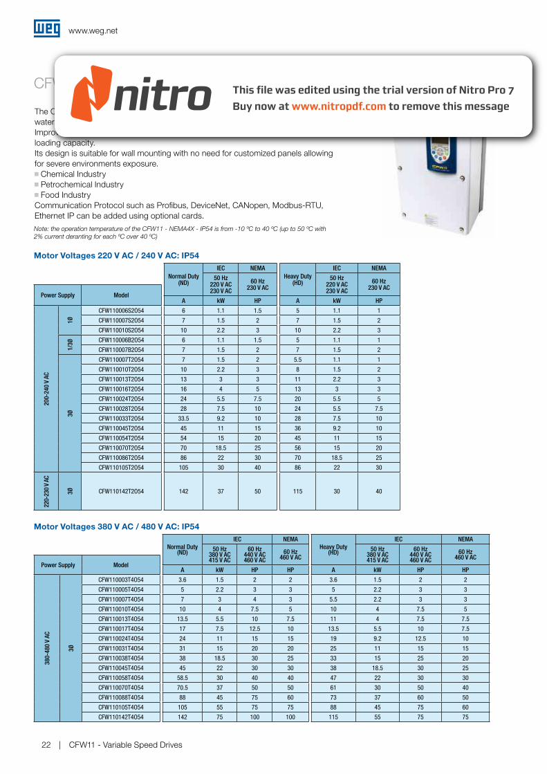
Motor Voltages 220 V AC / 240 V AC: IP54
Motor Voltages 380 V AC / 480 V AC: IP54
Normal Duty (ND)
IEC NEMA
Heavy Duty (HD)
IEC NEMA
50 Hz 380 V AC 415 V AC
60 Hz 440 V AC 460 V AC
60 Hz 460 V AC
50 Hz 380 V AC 415 V AC
60 Hz 440 V AC 460 V AC
60 Hz 460 V AC
Power Supply ModelA kW HP HP A kW HP HP
380-480 V AC
3Ø
CFW110003T4O54 3.6 1.5 2 2 3.6 1.5 2 2
CFW110005T4O54 5 2.2 3 3 5 2.2 3 3
CFW110007T4O54 7 3 4 3 5.5 2.2 3 3
CFW110010T4O54 10 4 7.5 5 10 4 7.5 5
CFW110013T4O54 13.5 5.5 10 7.5 11 4 7.5 7.5
CFW110017T4O54 17 7.5 12.5 10 13.5 5.5 10 7.5
CFW110024T4O54 24 11 15 15 19 9.2 12.5 10
CFW110031T4O54 31 15 20 20 25 11 15 15
CFW110038T4O54 38 18.5 30 25 33 15 25 20
CFW110045T4O54 45 22 30 30 38 18.5 30 25
CFW110058T4O54 58.5 30 40 40 47 22 30 30
CFW110070T4O54 70.5 37 50 50 61 30 50 40
CFW110088T4O54 88 45 75 60 73 37 60 50
CFW110105T4O54 105 55 75 75 88 45 75 60
CFW110142T4O54 142 75 100 100 115 55 75 75
CFW11 - NEMA4x / IP54
The CFW11 IP54 features an IP54 enclosure that protects the drive from splashingwater, corrosion and dust.Improved cooling fans ensure perfect functionality when operating at maximum loading capacity. Its design is suitable for wall mounting with no need for customized panels allowing for severe environments exposure. Chemical Industry Petrochemical Industry Food Industry
Communication Protocol such as Profibus, DeviceNet, CANopen, Modbus-RTU,Ethernet IP can be added using optional cards.
Note: the operation temperature of the CFW11 - NEMA4X - IP54 is from -10 ºC to 40 ºC (up to 50 ºC with
2% current deranting for each ºC over 40 ºC)
www.weg.net
CFW11 - Variable Speed Drives 23
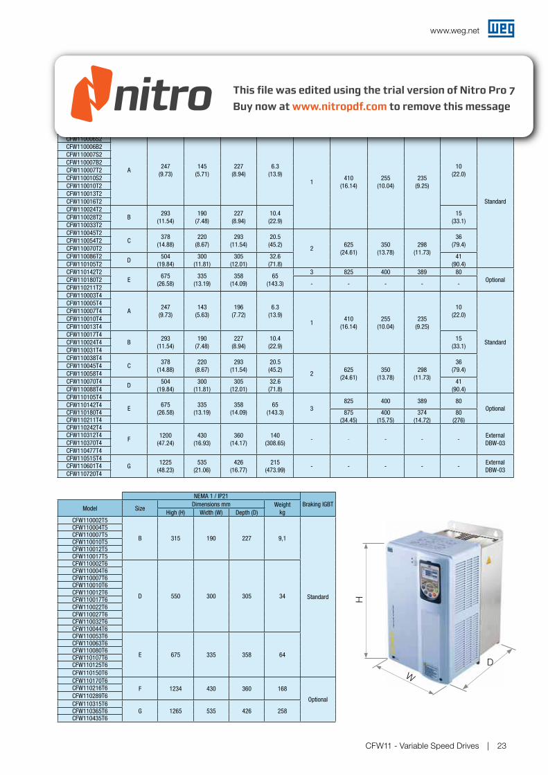
NEMA 1 / IP21 IP54
Model Size
Dimensions mm (in) Weight
kg (lb)Size
Dimensions mm (in) Weight
kg (lb)Braking IGBT
High (H) Width (W) Depth (D) High (H) Width (W) Depth (D)
CFW110006S2
A247
(9.73)
145
(5.71)
227
(8.94)
6.3
(13.9)
1410
(16.14)
255
(10.04)
235
(9.25)
10
(22.0)
Standard
CFW110006B2
CFW110007S2
CFW110007B2
CFW110007T2
CFW110010S2
CFW110010T2
CFW110013T2
CFW110016T2
CFW110024T2
B293
(11.54)
190
(7.48)
227
(8.94)
10.4
(22.9)
15
(33.1)CFW110028T2
CFW110033T2
CFW110045T2
C378
(14.88)
220
(8.67)
293
(11.54)
20.5
(45.2)2
625
(24.61)
350
(13.78)
298
(11.73)
36
(79.4)CFW110054T2
CFW110070T2
CFW110086T2D
504
(19.84)
300
(11.81)
305
(12.01)
32.6
(71.8)
41
(90.4)CFW110105T2
CFW110142T2
E675
(26.58)
335
(13.19)
358
(14.09)
65
(143.3)
3 825 400 389 80
OptionalCFW110180T2- - - - -
CFW110211T2
Dimensions and Weight
H
W
D
CFW110003T4
A247
(9.73)
143
(5.63)
196
(7.72)
6.3
(13.9)
1410
(16.14)
255
(10.04)
235
(9.25)
10
(22.0)
Standard
CFW110005T4
CFW110007T4
CFW110010T4
CFW110013T4
CFW110017T4
B293
(11.54)
190
(7.48)
227
(8.94)
10.4
(22.9)
15
(33.1)CFW110024T4
CFW110031T4
CFW110038T4
C378
(14.88)
220
(8.67)
293
(11.54)
20.5
(45.2)2
625
(24.61)
350
(13.78)
298
(11.73)
36
(79.4)CFW110045T4
CFW110058T4
CFW110070T4D
504
(19.84)
300
(11.81)
305
(12.01)
32.6
(71.8)
41
(90.4)CFW110088T4
CFW110105T4
E675
(26.58)
335
(13.19)
358
(14.09)
65
(143.3)3
825 400 389 80Optional
CFW110142T4CFW110180T4 875
(34.45)
400
(15.75)
374
(14.72)
80
(276)CFW110211T4CFW110242T4
F1200
(47.24)
430
(16.93)
360
(14.17)
140
(308.65)- - - - -
External
DBW-03
CFW110312T4
CFW110370T4
CFW110477T4
CFW110515T4
G1225
(48.23)
535
(21.06)
426
(16.77)
215
(473.99)- - - - -
External
DBW-03CFW110601T4
CFW110720T4
NEMA 1 / IP21
Braking IGBTModel Size
Dimensions mm Weight
kgHigh (H) Width (W) Depth (D)
CFW110002T5
B 315 190 227 9,1
Standard
CFW110004T5CFW110007T5CFW110010T5CFW110012T5CFW110017T5CFW110002T6
D 550 300 305 34
CFW110004T6CFW110007T6CFW110010T6CFW110012T6CFW110017T6CFW110022T6CFW110027T6CFW110032T6CFW110044T6CFW110053T6
E 675 335 358 64
CFW110063T6CFW110080T6CFW110107T6CFW110125T6
CFW110150T6
CFW110170T6
F 1234 430 360 168
Optional
CFW110216T6
CFW110289T6
CFW110315T6G 1265 535 426 258CFW110365T6
CFW110435T6
www.weg.net
CFW11 - Variable Speed Drives24
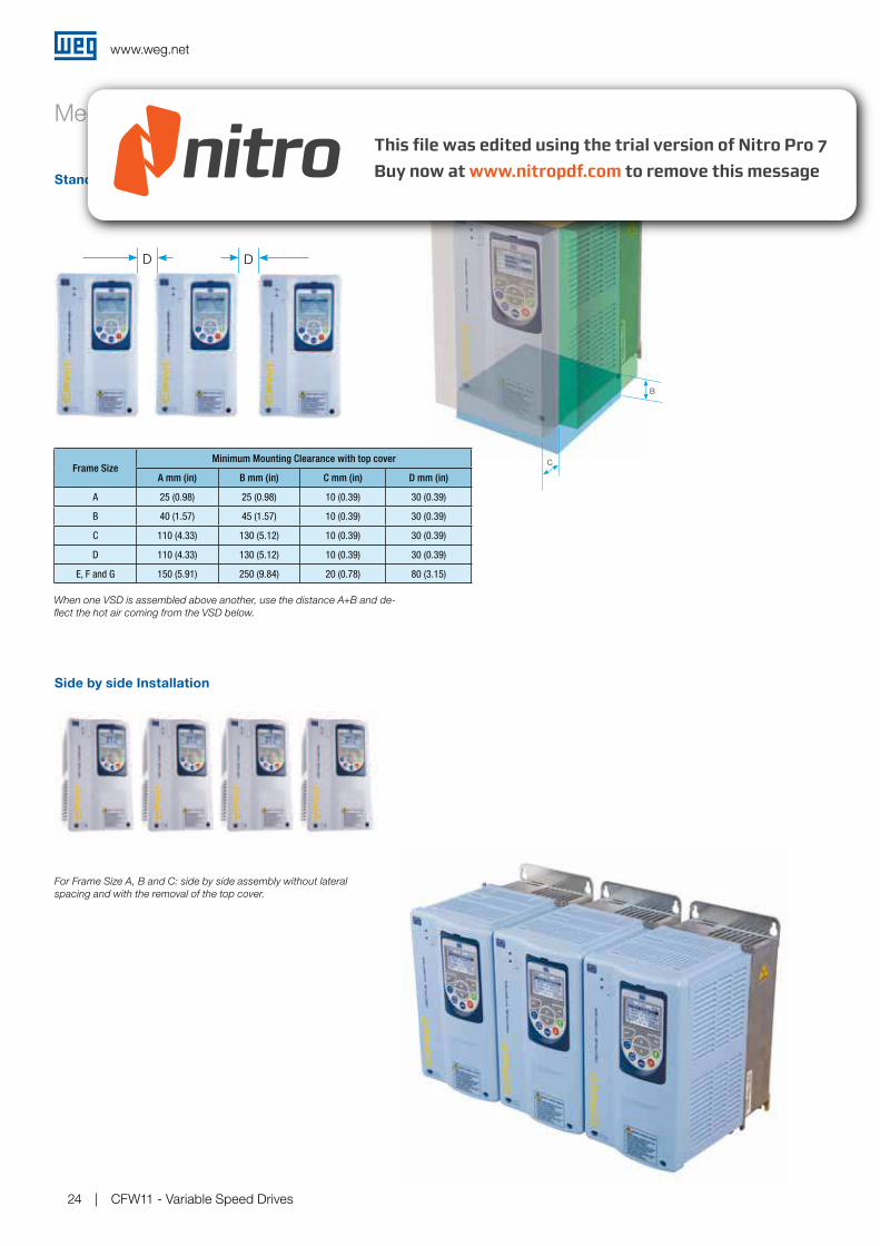
Mechanical Mounting
Standard Installation
When one VSD is assembled above another, use the distance A+B and de-
flect the hot air coming from the VSD below.
A
B
C
Side by side Installation
For Frame Size A, B and C: side by side assembly without lateral
spacing and with the removal of the top cover.
Frame SizeMinimum Mounting Clearance with top cover
A mm (in) B mm (in) C mm (in) D mm (in)
A 25 (0.98) 25 (0.98) 10 (0.39) 30 (0.39)
B 40 (1.57) 45 (1.57) 10 (0.39) 30 (0.39)
C 110 (4.33) 130 (5.12) 10 (0.39) 30 (0.39)
D 110 (4.33) 130 (5.12) 10 (0.39) 30 (0.39)
E, F and G 150 (5.91) 250 (9.84) 20 (0.78) 80 (3.15)
DD
www.weg.net
CFW11 - Variable Speed Drives 25
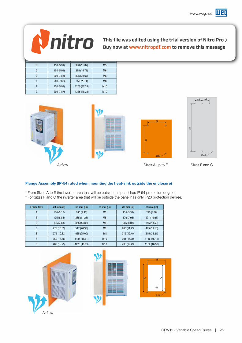
Mechanical Installation | Panel Assembly
Surface Assembly
Flange Assembly (IP-54 rated when mounting the heat-sink outside the enclosure)
AirflowAirflow
Frame Size a2 mm (in) b2 mm (in) c2 mm (in)
A 115 (4.53) 250 (9.85) M5
B 150 (5.91) 300 (11.82) M5
C 150 (5.91) 375 (14.77) M6
D 200 (7.88) 525 (20.67) M8
E 200 (7.88) 650 (25.60) M8
F 150 (5.91) 1200 (47.24) M10
G 200 (7.87) 1225 (48.23) M10
Frame Size a3 mm (in) b3 mm (in) c3 mm (in) d3 mm (in) e3 mm (in)
A 130 (5.12) 240 (9.45) M5 135 (5.32) 225 (8.86)
B 175 (6.84) 285 (11.23) M5 179 (7.05) 271 (10.65)
C 195 (7.68) 365 (14.38) M6 205 (8.08) 345 (13.59)
D 275 (10.83) 517 (20.36) M8 285 (11.23) 485 (19.10)
E 275 (10.83) 635 (25.00) M8 315 (12.40) 615 (24.21)
F 350 (13.78) 1185 (46.61) M10 391 (15.39) 1146 (45.12)
G 400 (15.75) 1220 (48.03) M10 495 (19.49) 1182 (46.53)
AirflowAirflowAirflow
Sizes A up to E Sizes F and G
* From Sizes A to E the inverter area that will be outside the panel has IP 54 protection degree.* For Sizes F and G the inverter area that will be outside the panel has only IP20 protection degree.
www.weg.net
CFW11 - Variable Speed Drives26
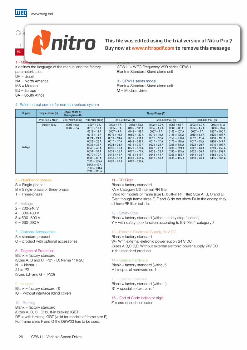
1 - Market identificationIt defines the language of the manual and the factory parameterizationBR = Brazil NA = North America MS = MercosulEU = EuropeSA = South Africa
Coding
4- Rated output current for normal overload system
5 – Number of phasesS = Single-phaseB = Single-phase or three-phaseT = Three-phase
6 - Voltage2 = 200-240 V4 = 380-480 V5 = 500 -600 V6 = 660-690 V
7 - Optional AccessoriesS = standard productO = product with optional accessories
8 - Degree of Protection Blank = factory standard (Sizes A, B and C: IP21 - D: Nema 1/ IP20)N1 = Nema 121 = IP21(Sizes E,F and G - IP20)
9 - KeypadBlank = factory standard (1)IC = without interface (blind cover)
10 - BrakingBlank = factory standard (Sizes A, B, C , D: built-in braking IGBT) DB = with braking IGBT (valid for models of frame size E)For frame sizes F and G the DBW03 has to be used.
11 - RFI Filter Blank = factory standardFA = Category C3 internal RFI filter(Valid for models of frame (size E: built-in RFI filter) Size A, B, C and D)Even though frame sizes E, F and G do not show FA in the coding they all have RF filter built-in.
12 - Safety StopBlank = factory standard (without safety stop function)Y = with safety stop function according to EN-954-1 category 3
13 - External Electronic Supply 24 V DC Blank = factory standard W= With external eletronic power supply 24 V DC(Sizes A,B,C,D,E: Without external eletronic power supply 24V DC in the standard product)
14 – Special hardwareBlank = factory standard (without)H1 = special hardware nr. 1
15 – Special SoftwareBlank = factory standard (without)S1 = special software nr. 1
16 – End of Code indicator digitZ = end of code indicator
EU CFW11 0016 T 4 S_ _ _ _ _ _ _ _
Z1 2 3 4 5 6 7 8 9 10 11 12 13 14 15 16 _
2 - Line CFW11 = WEG Frequency VSD series CFW11Blank = Standard Stand alone unit
3 - CFW11 series modelBlank = Standard Stand alone unitM = Modular drive
Supply Single-phase (S) Single-phase or Three-phase (B)
Three-Phase (T)
Voltage
200-240 V AC (2) 200-240 V AC (2) 200-240 V AC (2) 380-480 V AC (4) 500-600 V AC (5) 660-690 V AC (6)
0010 = 10 A 0006 = 6 A0007 = 7 A
0007 = 7 A0010 = 10 A0013 = 13 A0016 = 16 A0024 = 24 A0028 = 28 A0033 = 33 A0045 = 45 A0054 = 54 A0070 = 70 A0086 = 86 A0105 = 105 A0142 =142 A0180 = 180 A0211 = 211 A
0003 = 3 A0005 = 5 A0007 = 7 A0010 = 10 A0013 = 13 A0017 = 17 A0024 = 24 A0031 = 31 A0038 = 38 A0045 = 45 A0058 = 58 A0070 = 70 A
0088 = 88 A0105 = 105 A0142 = 142 A0180 = 180 A0211 = 211 A0242 = 242 A0312 = 312 A0370 = 370 A0477 = 477 A0515 = 515 A0601 = 601 A0720 = 720 A
0002 = 2,9 A0004 = 4,2 A0007 = 7 A0010 = 10 A0012 = 12 A0017 = 17 A0022 = 22 A0027 = 27 A0032 = 32 A0044 = 44 A0053 = 53 A
0063 = 63 A0080 = 80 A0107 = 107 A0125 = 125 A0150 = 150 A0170 = 170 A0216 = 216 A0289 = 289 A0315 = 315 A0365 = 365 A0435 = 435 A
0002 = 2,9 A0004 = 4,2 A0007 = 7 A
0010 = 8,5 A0012 = 11 A0017 = 15 A0022 = 20 A0027 = 24 A0032 = 30 A0044 = 35 A0053 = 46 A
0063 = 54 A0080 = 73 A0107 = 100 A0125 = 108 A0150 = 130 A0170 = 147 A0216 = 195 A0289 = 259 A0315 = 259 A0365 = 312 A0435 = 365 A
www.weg.net
CFW11 - Variable Speed Drives 27
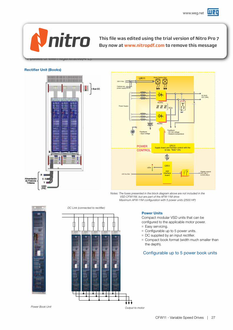
CFW11M - Modular Drive
Power Units
Compact modular VSD units that can be configured to the applicable motor power. Easy servicing. Configurable up to 5 power units. DC supplied by an input rectifier. Compact book format (width much smaller than the depth).
Rectifier Unit (Books)
The CFW11M is the new generation of WEG frequency inverters for large power ranges. It ranges from
350kW to 2000kW (350 to 2500HP) rated at 380-480 V / 500-600 V / 660-690 V with the option for 6,
12 pulses or even regenerative(AFE).
Notes: The fuses presented in the block diagram above are not included in the
VSD CFW11M, but are part of the AFW-11M drive
Maximum AFW-11M configuration with 5 power units (2500 HP)
Configurable up to 5 power book units
Power Book Unit
DC Link (connected to rectifier)
Output to motor
PE
NTCs
Rectifier
Rectifier
Power Section Fans
220 V Ext.
Cabinet aux.power supply
Power Supply
Digitals outputsDO1 (RL1)to DO3 (RL3)
+24 Vcc Ext.
LEDs
Feedback:- DC link voltage- Heatsink temperature
Feedback:- Input voltage
UR11
DC BUS(DC LINK)
POWER
CONTROL
CIR11
userinterface
board
CPC11Supply board and thyristor control with the
32 bits ”RISC” CPU
www.weg.net
CFW11 - Variable Speed Drives28
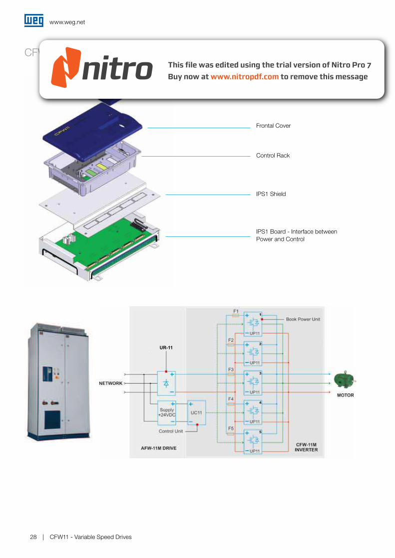
CFW11M - Modular Drive
Keypad
Frontal Cover
Control Rack
IPS1 Shield
IPS1 Board - Interface between Power and Control
UR-11
www.weg.net
CFW11 - Variable Speed Drives 29
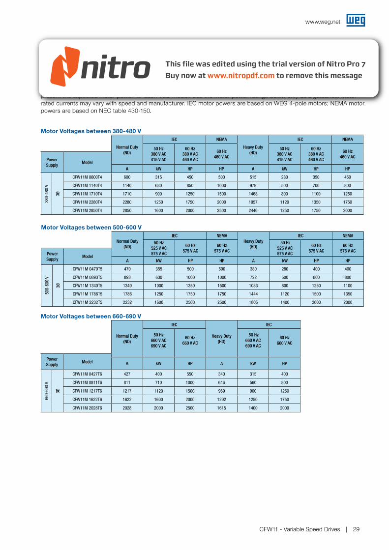
Sizing the Drive
The correct way to select a VSD is matching its output current with the motor rated current. However, the tables below present the expected motor power for each VSD model. Use the motor power ratings below only as a guidance. Motor rated currents may vary with speed and manufacturer. IEC motor powers are based on WEG 4-pole motors; NEMA motor powers are based on NEC table 430-150.
Motor Voltages between 380-480 V
CFW11M - Drive Ratings
Motor Voltages between 500-600 V
Motor Voltages between 660-690 V
Normal Duty
(ND)
IEC NEMA
Heavy Duty
(HD)
IEC NEMA
50 Hz
380 V AC
415 V AC
60 Hz
380 V AC
460 V AC
60 Hz
460 V AC
50 Hz
380 V AC
415 V AC
60 Hz
380 V AC
460 V AC
60 Hz
460 V ACPower
SupplyModel
A kW HP HP A kW HP HP
38
0-4
80
V
3Ø
CFW11M 0600T4 600 315 450 500 515 280 350 450
CFW11M 1140T4 1140 630 850 1000 979 500 700 800
CFW11M 1710T4 1710 900 1250 1500 1468 800 1100 1250
CFW11M 2280T4 2280 1250 1750 2000 1957 1120 1350 1750
CFW11M 2850T4 2850 1600 2000 2500 2446 1250 1750 2000
Normal Duty
(ND)
IEC NEMA
Heavy Duty
(HD)
IEC NEMA
50 Hz
525 V AC
575 V AC
60 Hz
575 V AC
60 Hz
575 V AC
50 Hz
525 V AC
575 V AC
60 Hz
575 V AC
60 Hz
575 V ACPower
SupplyModel
A kW HP HP A kW HP HP
50
0-6
00
V
3Ø
CFW11M 0470T5 470 355 500 500 380 280 400 400
CFW11M 0893T5 893 630 1000 1000 722 500 800 800
CFW11M 1340T5 1340 1000 1350 1500 1083 800 1250 1100
CFW11M 1786T5 1786 1250 1750 1750 1444 1120 1500 1350
CFW11M 2232T5 2232 1600 2500 2500 1805 1400 2000 2000
Normal Duty
(ND)
IEC
Heavy Duty
(HD)
IEC
50 Hz
660 V AC
690 V AC
60 Hz
660 V AC
50 Hz
660 V AC
690 V AC
60 Hz
660 V AC
Power
SupplyModel A kW HP A kW HP
66
0-6
90
V
3Ø
CFW11M 0427T6 427 400 550 340 315 400
CFW11M 0811T6 811 710 1000 646 560 800
CFW11M 1217T6 1217 1120 1500 969 900 1250
CFW11M 1622T6 1622 1600 2000 1292 1250 1750
CFW11M 2028T6 2028 2000 2500 1615 1400 2000
www.weg.net
CFW11 - Variable Speed Drives30
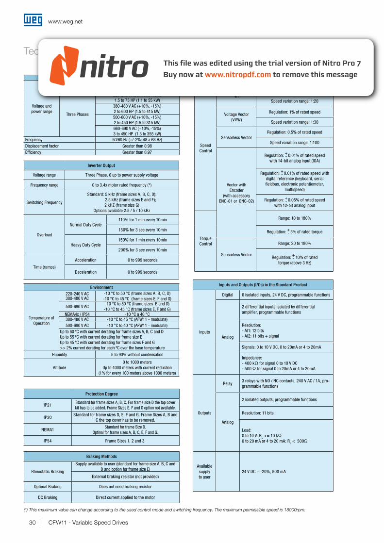
Technical Data
Inverter Output
Voltage range Three Phase, 0 up to power supply voltage
Frequency range 0 to 3.4x motor rated frequency (*)
Switching Frequency
Standard: 5 kHz (frame sizes A, B, C, D);
2.5 kHz (frame sizes E and F);
2 kHZ (frame size G)
Options available 2.5 / 5 / 10 kHz
Overload
Normal Duty Cycle 110% for 1 min every 10min
150% for 3 sec every 10min
Heavy Duty Cycle150% for 1 min every 10min
200% for 3 sec every 10min
Time (ramps)
Acceleration 0 to 999 seconds
Deceleration 0 to 999 seconds
Protection Degree
IP21Standard for frame sizes A, B, C. For frame size D the top cover
kit has to be added. Frame Sizes E, F and G option not available.
IP20Standard for frame sizes D, E, F and G. Frame Sizes A, B and
C the top cover has to be removed.
NEMA1Standard for frame Size D.
Optinal for frame sizes A, B, C, E, F and G.
IP54 Frame Sizes 1, 2 and 3.
Braking Methods
Rheostatic Braking
Supply available to user (standard for frame size A, B, C and
D and option for frame size E)
External braking resistor (not provided)
Optimal Braking Does not need braking resistor
DC Braking Direct current applied to the motor
Inputs and Outputs (I/Os) in the Standard Product
Inputs
Digital 6 isolated inputs, 24 V DC, programmable functions
Analog
2 differential inputs isolated by differential
amplifier, programmable functions
Resolution:
- AI1: 12 bits
- AI2: 11 bits + signal
Signals: 0 to 10 V DC, 0 to 20mA or 4 to 20mA
Impedance:
- 400 kΩ for signal 0 to 10 V DC
- 500 Ω for signal 0 to 20mA or 4 to 20mA
Outputs
Relay3 relays with NO / NC contacts, 240 V AC / 1A, pro-
grammable functions
Analog
2 isolated outputs, programmable functions
Resolution: 11 bits
Load:
0 to 10 V: RL >= 10 kΩ0 to 20 mA or 4 to 20 mA: RL < 500Ω
Available
supply
to user
24 V DC + -20%, 500 mA
(*) This maximum value can change according to the used control mode and switching frequency. The maximum permissible speed is 18000rpm.
Performance
Speed
Control
V/f
Regulation: 1% of rated speed
Speed variation range: 1:20
Voltage Vector
(VVW)
Regulation: 1% of rated speed
Speed variation range: 1:30
Sensorless Vector
Regulation: 0.5% of rated speed
Speed variation range: 1:100
Vector with
Encoder
(with accessory
ENC-01 or ENC-02)
Regulation: 0.01% of rated speed
with 14-bit analog input (IOA)
Regulation: 0.01% of rated speed with
digital reference (keyboard, serial
fieldbus, electronic potentiometer,
multispeed)
Regulation: 0.05% of rated speed
with 12-bit analog input
Torque
Control
Range: 10 to 180%
Regulation: 5% of rated torque
Sensorless Vector
Range: 20 to 180%
Regulation: 10% of rated
torque (above 3 Hz)
+-
+-
+-
+-
+-
Power supply and Power Range
Voltage and
power range
Sigle Phase220-240 V AC (+10%, -15%)
1.5 to 3 HP (1.1 to 2.2 kW)
Three Phases
220-240 V AC (+10%, -15%)
1.5 to 75 HP (1.1 to 55 kW)
380-480 V AC (+10%, -15%)
2 to 600 HP (1.5 to 415 kW)
500-600 V AC (+10%, -15%)
2 to 450 HP (1.5 to 315 kW)
660-690 V AC (+10%,-15%)
3 to 450 HP (1.5 to 355 kW)
Frequency 50/60 Hz (+/-2%: 48 a 63 Hz)
Displacement factor Greater than 0.98
Efficiency Greater than 0.97
Environment
Temperature of
Operation
220-240 V AC380-480 V AC
-10 °C to 50 °C (frame sizes A, B, C, D)
-10 °C to 45 °C (frame sizes E, F and G)
500-690 V AC-10 °C to 50 °C (frame sizes B and D)
-10 °C to 45 °C (frame sizes E, F and G)NEMA4x / IP54 -10 °C a 40 °C380-480 V AC -10 °C to 45 °C (AFW11 - modulate)
500-690 V AC -10 °C to 40 °C (AFW11 - modulate)
Up to 60 ºC with current derating for frame sizes A, B, C and D
Up to 55 ºC with current derating for frame size E
Up to 45 ºC with current derating for frame sizes F and G
>> 2% current derating for each ºC over the base temperature
Humidity 5 to 90% without condensation
Altitude
0 to 1000 meters
Up to 4000 meters with current reduction
(1% for every 100 meters above 1000 meters)
www.weg.net
CFW11 - Variable Speed Drives 31
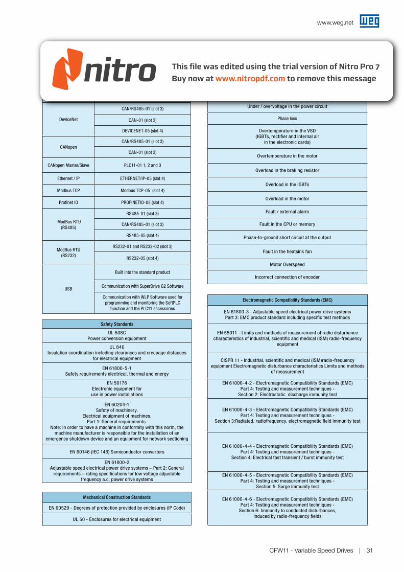
Protections
Overcurrent / short circuit
Under / overvoltage in the power circuit
Phase loss
Overtemperature in the VSD
(IGBTs, rectifier and internal air
in the electronic cards)
Overtemperature in the motor
Overload in the braking resistor
Overload in the IGBTs
Overload in the motor
Fault / external alarm
Fault in the CPU or memory
Phase-to-ground short circuit at the output
Fault in the heatsink fan
Motor Overspeed
Incorrect connection of encoder
Communication
Profibus DPPROFIBUS DP-01 (slot 3)
PROFDP-05 (slot 4)
DeviceNet
CAN/RS485-01 (slot 3)
CAN-01 (slot 3)
DEVICENET-05 (slot 4)
CANopen
CAN/RS485-01 (slot 3)
CAN-01 (slot 3)
CANopen Master/Slave PLC11-01 1, 2 and 3
Ethernet / IP ETHERNET/IP-05 (slot 4)
Modbus TCP Modbus TCP-05 (slot 4)
Profinet IO PROFINETIO-05 (slot 4)
ModBus RTU
(RS485)
RS485-01 (slot 3)
CAN/RS485-01 (slot 3)
RS485-05 (slot 4)
ModBus RTU
(RS232)
RS232-01 and RS232-02 (slot 3)
RS232-05 (slot 4)
USB
Built into the standard product
Communication with SuperDrive G2 Software
Communication with WLP Software used for
programming and monitoring the SoftPLC
function and the PLC11 accessories
Safety Standards
UL 508C
Power conversion equipment
UL 840
Insulation coordination including clearances and creepage distances
for electrical equipment
EN 61800-5-1
Safety requirements electrical, thermal and energy
EN 50178
Electronic equipment for
use in power installations
EN 60204-1
Safety of machinery.
Electrical equipment of machines.
Part 1: General requirements.
Note: In order to have a machine in conformity with this norm, the
machine manufacturer is responsible for the installation of an
emergency shutdown device and an equipment for network sectioning
EN 60146 (IEC 146) Semiconductor converters
EN 61800-2
Adjustable speed electrical power drive systems – Part 2: General
requirements – rating specifications for low voltage adjustable
frequency a.c. power drive systems
Electromagnetic Compatibility Standards (EMC)
EN 61800-3 - Adjustable speed electrical power drive systems
Part 3: EMC product standard including specific test methods
EN 55011 - Limits and methods of measurement of radio disturbance
characteristics of industrial, scientific and medical (ISM) radio-frequency
equipment
CISPR 11 - Industrial, scientific and medical (ISM)radio-frequency
equipment Electromagnetic disturbance characteristics Limits and methods
of measurement
EN 61000-4-2 - Electromagnetic Compatibility Standards (EMC)
Part 4: Testing and measurement techniques -
Section 2: Electrostatic discharge immunity test
EN 61000-4-3 - Electromagnetic Compatibility Standards (EMC)
Part 4: Testing and measurement techniques -
Section 3:Radiated, radiofrequency, electromagnetic field immunity test
EN 61000-4-4 - Electromagnetic Compatibility Standards (EMC)
Part 4: Testing and measurement techniques -
Section 4: Electrical fast transient / burst immunity test
EN 61000-4-5 - Electromagnetic Compatibility Standards (EMC)
Part 4: Testing and measurement techniques -
Section 5: Surge immunity test
EN 61000-4-6 - Electromagnetic Compatibility Standards (EMC)
Part 4: Testing and measurement techniques -
Section 6: Immunity to conducted disturbances,
induced by radio-frequency fields
Technical Data
Mechanical Construction Standards
EN 60529 - Degrees of protection provided by enclosures (IP Code)
UL 50 - Enclosures for electrical equipment
WEG Worldwide Operations
ARGENTINA
WEG EQUIPAMIENTOS ELECTRICOS San Francisco - CordobaPhone: +54 (3564) [email protected]
www.weg.net/ar
WEG PINTURAS - PulverluxBuenos AiresPhone: +54 (11) [email protected]
AUSTRALIA
WEG AUSTRALIAVictoria Phone: 61 (3) 9765 [email protected]
www.weg.net/au
AUSTRIA
WATT DRIVE - WEG GroupMarkt Piesting - VienaPhone: +43 (0) 2633 404 [email protected]
www.wattdrive.com
BENELUX
WEG BENELUXNivelles - BelgiumPhone: +55 (67) [email protected]
www.weg.net/be
BRAZIL
WEG EQUIPAMENTOS ELÉTRICOSJaraguá do Sul - Santa CatarinaPhone: +55 (47) [email protected]
www.weg.net/br
CHILE
WEG CHILESantiagoPhone: (56-2) 784 [email protected]
www.weg.net/cl
CHINA
WEG NANTONGNantong - Jiangsu Phone: (86) [email protected]
www.weg.net/cn
COLOMBIA
WEG COLOMBIABogotáPhone: (57 1) 416 [email protected]
www.weg.net/co
FRANCE
WEG FRANCESaint Quentin Fallavier - LyonPhone: +33 (0) 4 74 99 11 [email protected]
www.weg.net/fr
GERMANY
WEG GERMANY Kerpen - North Rhine Westphalia Phone: +49 (0)2237/[email protected]
www.weg.net/de
GHANA
ZEST ELECTRIC GHANA WEG GroupAccraPhone: 233 30 27 664 [email protected]
www.zestghana.com.gh
INDIA
WEG ELECTRIC INDIABangalore - KarnatakaPhone: +91-80-4128 2007 [email protected]
www.weg.net/in
WEG INDUSTRIES INDIAHosur - Tamil NaduPhone: [email protected]
www.weg.net/in
ITALY
WEG ITALIACinisello Balsamo - MilanoPhone: (39) 02 [email protected]
www.weg.net/it
JAPAN
WEG ELECTRIC MOTORSJAPANYokohama City - KanagawaPhone: (81) 45 440 [email protected]
www.weg.net/jp
MEXICO
WEG MEXICOHuehuetoca Phone: +52 (55) 5321 [email protected]
www.weg.net/mx
VOLTRAN - WEG GroupTizayuca - HidalgoPhone: + 52 (77) 9796 3790www.voltran.com.mx
NETHERLANDS
WEG NETHERLANDS Oldenzaal - OverijsselPhone: +31 (0) [email protected]
www.weg.net/nl
PERU
WEG PERULimaPhone: (51 1) 472 [email protected]
www.weg.net/pe
PORTUGAL
WEG EUROMaia - PortoPhone: +351 229 477 [email protected]
www.weg.net/pt
RUSSIA
WEG RUSSIA Saint Petersburg Phone: +7(812)363-21-72 [email protected]
www.weg.net/ru
SOUTH AFRICA
ZEST ELECTRIC MOTORSWEG Group JohannesburgPhone: (27-11) [email protected]
www.zest.co.za
SPAIN
WEG IBERIAMadridPhone: (34) 916 553 [email protected]
www.weg.net/es
SINGAPORE
WEG SINGAPORE SingaporePhone: +65 6858 [email protected]
www.weg.net/sg
SCANDINAVIA
WEG SCANDINAVIAKungsbacka - SwedenPhone: (46) 300 [email protected]
www.weg.net/se
UK
WEG ELECTRIC MOTORS U.K.Worcestershire - EnglandPhone: 44 (0)1527 [email protected]
www.weg.net/uk
UNITED ARAB EMIRATES
WEG MIDDLE EAST DubaiPhone: +971 (4) 8130800 [email protected]
www.weg.net/ae
USA
WEG ELECTRIC Duluth - GeorgiaPhone: +1 678 249 [email protected]
www.weg.net/us
ELECTRIC MACHINERYWEG GroupMinneapolis - MinnesotaPhone: +1 612 378 8000www.electricmachinery.com
VENEZUELA
WEG INDUSTRIAS VENEZUELAValencia - CaraboboPhone: (58) 241 [email protected]
www.weg.net/ve
Co
d: 5
001
907
6 | R
ev: 0
8 | D
ate
(m/y
): 0
8/2
012
The
val
ues
show
n ar
e su
bje
ct t
o ch
ang
e w
itho
ut p
rior
notic
e.
For those countries where there is not a WEG own operation, find our local distributor at www.weg.net.
Grupo WEG - Automation Business Unit Jaraguá do Sul - SC - Brazil Phone: +55 (47) 3276-4000 [email protected]
www.weg.net