Embed Size (px)
Citation preview
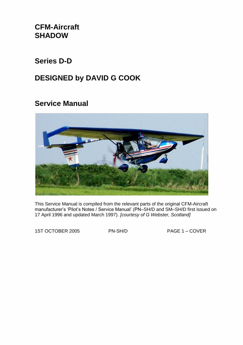
CFM-Aircraft SHADOW Series D-D DESIGNED by DAVID G COOK Service Manual
This Service Manual is compiled from the relevant parts of the original CFM-Aircraft manufacturer’s ‘Pilot’s Notes / Service Manual’ (PN–SH/D and SM–SH/D first issued on 17 April 1996 and updated March 1997). [courtesy of G Webster, Scotland] 1ST OCTOBER 2005 PN-SH/D PAGE 1 – COVER
Annexes - Shadow ‘D’ PILOTS NOTES List of modified, new and abandoned pages. Comparison between Pilots Notes for C-Series and D-Series. Document Reference PN-SH/C for the Shadow C-Series PN-SH/D for the Shadow D-Series The ROTAX 582-UL DCDI Operators Manual is considered part of the D-Series Pilots Notes PN-SH/D. The new and updated pages are marked “N”. Pages Title of Page Amendment Status 1 Cover 1st October 2005 2 Annexes 1st October 2005 3 Series Key 1st October 2005 4 Page Titles 1st October 2005 5 Certification / Modifications 1st October 2005 6 Table of Contents 1st October 2005 7 Table of Contents 1st October 2005 8 Annex B 1st October 2005 9 Annex B 1st October 2005 10 Annex B 1st October 2005 11 Annex B 1st October 2005 12 Annex B 1st October 2005 13 Annex B 1st October 2005 14 Annex B 1st October 2005 15 Annex B 1st October 2005 16 Annex B 1st October 2005 17 Annex B 1st October 2005 18 Annex B 1st October 2005 19 Annex B 1st October 2005 20 Annex B 1st October 2005 21 Annex B 1st October 2005 22 Annex C 1st October 2005 23 Annex C 1st October 2005 24 Annex D 1st October 2005 25 Annex D 1st October 2005 26 Annex D 1st October 2005 27 Annex D 1st October 2005 28 Annex D 1st October 2005 29 Annex D 1st October 2005 30 Annex D 1st October 2005 31 Annex D 1st October 2005 32 Annex E 1st October 2005 33 Annex E 1st October 2005 36 Annex F 1st October 2005 35 Annex F 1st October 2005 36 Annex G 1st October 2005 37 Annex G 1st October 2005 38 Annex H 1st October 2005 39 Annex J 1st October 2005 40 Annex J 1st October 2005 41 Annex K 1st October 2005 42 Annex K 1st October 2005 43 Annex K 1st October 2005 44 Annex K 1st October 2005 45 Annex L 1st October 2005 46 Annex M 1st October 2005 47 Annex M 1st October 2005 48 Annex M 1st October 2005 49 Annex M 1st October 2005 50 Annex M 1st October 2005 51 Annex M 1st October 2005 52 Annex M 1st October 2005
1ST OCTOBER 2005 PN-SH/D PAGE 2 – ANNEXES
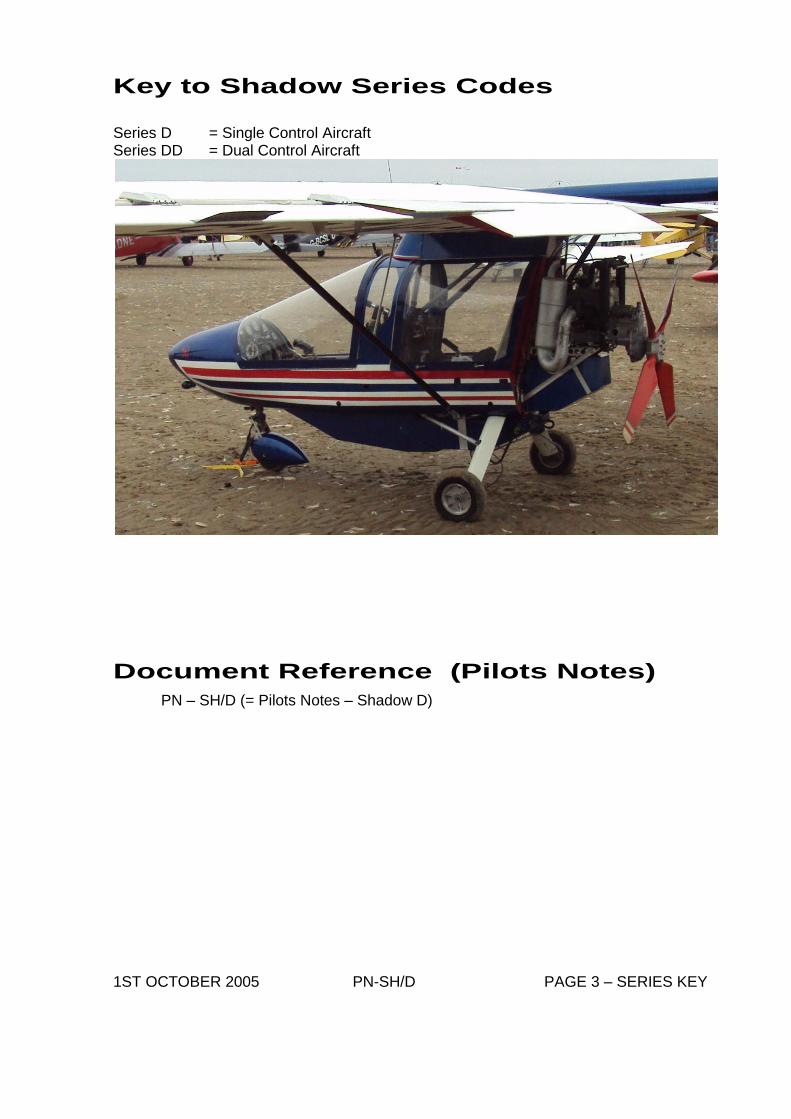
Key to Shadow Series Codes
Series D = Single Control Aircraft Series DD = Dual Control Aircraft
Document Reference (Pilots Notes)
PN – SH/D (= Pilots Notes – Shadow D) 1ST OCTOBER 2005 PN-SH/D PAGE 3 – SERIES KEY
Page Titles
– List of Effective Pages Date of Issue of Original Pages – 17 April 1996 Page # Title of Page Amendment Date 1 Cover 1st October 2005 2 Annexes 1st October 2005 3 Series Key 1st October 2005 4 Page Titles 1st October 2005 5 Certification / Modifications 1st October 2005 6 Annex A - Table of Contents 1st October 2005 7 Annex A - Table of Contents 1st October 2005 8 Annex B – Description 1st October 2005 9 Annex B – Description 1st October 2005 10 Annex B – Description 1st October 2005 11 Annex B – Description 1st October 2005 12 Annex B – Description 1st October 2005 13 Annex B – Description 1st October 2005 14 Annex B – Description 1st October 2005 15 Annex B – Description 1st October 2005 16 Annex B – Description 1st October 2005 17 Annex B – Description 1st October 2005 18 Annex B – Description 1st October 2005 19 Annex B – Description 1st October 2005 20 Annex B – Description 1st October 2005 21 Annex B – Description 1st October 2005 22 Annex C – Limitations 1st October 2005 23 Annex C – Limitations 1st October 2005 24 Annex D – Handling 1st October 2005 25 Annex D – Handling 1st October 2005 26 Annex D – Handling 1st October 2005 27 Annex D – Handling 1st October 2005 28 Annex D – Handling 1st October 2005 29 Annex D – Handling 1st October 2005 30 Annex D – Handling 1st October 2005 31 Annex D – Handling 1st October 2005 32 Annex E – Rigging/De-rigging 1st October 2005 33 Annex E – Rigging/De-rigging 1st October 2005 34 Annex F – Markings/Placards 1st October 2005 35 Annex F – Markings/Placards 1st October 2005 36 Annex G – Graphs 1st October 2005 37 Annex G – Graphs 1st October 2005 38 Annex H – Electric Trim 1st October 2005 39 Annex J – Rear Seat Fuel Tank 1st October 2005 40 Annex J – Rear Seat Fuel Tank 1st October 2005 41 Annex K – Weight/CG Schedule 1st October 2005 42 Annex K – Weight/CG Schedule 1st October 2005 43 Annex K – Weight/CG Schedule 1st October 2005 44 Annex K – Weight/CG Schedule 1st October 2005 45 Annex L - Mandatory Permit Directives 1ST October 2005 46 Annex M - Rotax Maintenance 1st October 2005 47 Annex M - Rotax Maintenance 1st October 2005 48 Annex M - Rotax Maintenance 1st October 2005 49 Annex M - Rotax Maintenance 1st October 2005 50 Annex M - Rotax Maintenance 1st October 2005 51 Annex M - Rotax Maintenance 1st October 2005 52 Annex M - Rotax Maintenance 1st October 2005
1ST OCTOBER 2005 PN-SH/D PAGE 4 – PAGE LIST
Certification / Modifications
Certification
BCAR Section S Issue 1 dated April 1995 Definition of Basic Standard: CFM Drawing No. see AAN 26063
Approved Optional Modifications
The installation of all optional modifications is to be inspected by a BMAA inspector and an entry made in the appropriate logbook(s). Note that there are other approved modifications that are not listed here. Mod No. Subject Status AAN No. 036 Aileron size reduction Minor - 037 Series D submission Major 26063 038 Fuel tank restriction Minor 26063 040 Rudder / Fin post insert Minor 25545 042 TADS Change – Weight & Balance change Minor - MAAN 1762 Crosbie replacement undercarriage Major - MAAN 1877 elevator ‘flutter’ friction device
Issue History
Issue No. Reason and signatory 1 - 24.02.98 Initial Issue (R J HARDY) 2 - 02.03.98 Editorial changes (R J HARDY) 3 - 16.02.99 Corrections to CG limits (R J HARDY) 4 – 12.05.03 To include weighing information, editorial changes and the inclusion of
MPD 2003-005 and BMAA SB 1682 issue 1. (J BARRATT) 5 – 05.07.04 Change to the organisation responsible for continued airworthiness
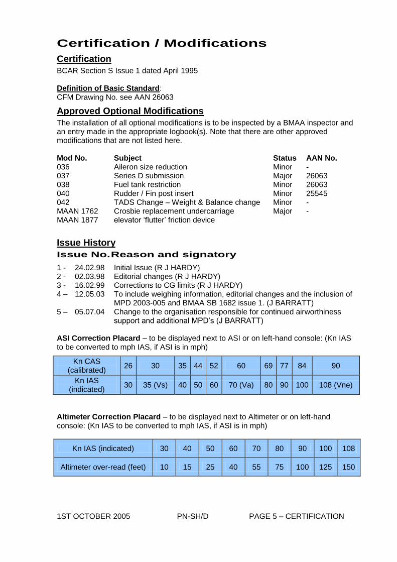
support and additional MPD’s (J BARRATT) ASI Correction Placard – to be displayed next to ASI or on left-hand console: (Kn IAS to be converted to mph IAS, if ASI is in mph)
Altimeter Correction Placard – to be displayed next to Altimeter or on left-hand console: (Kn IAS to be converted to mph IAS, if ASI is in mph)
Kn IAS (indicated) 30 40 50 60 70 80 90 100 108
Altimeter over-read (feet) 10 15 25 40 55 75 100 125 150
1ST OCTOBER 2005 PN-SH/D PAGE 5 – CERTIFICATION
Kn CAS (calibrated)
26 30 35 44 52 60 69 77 84 90
Kn IAS (indicated)
30 35 (Vs) 40 50 60 70 (Va) 80 90 100 108 (Vne)
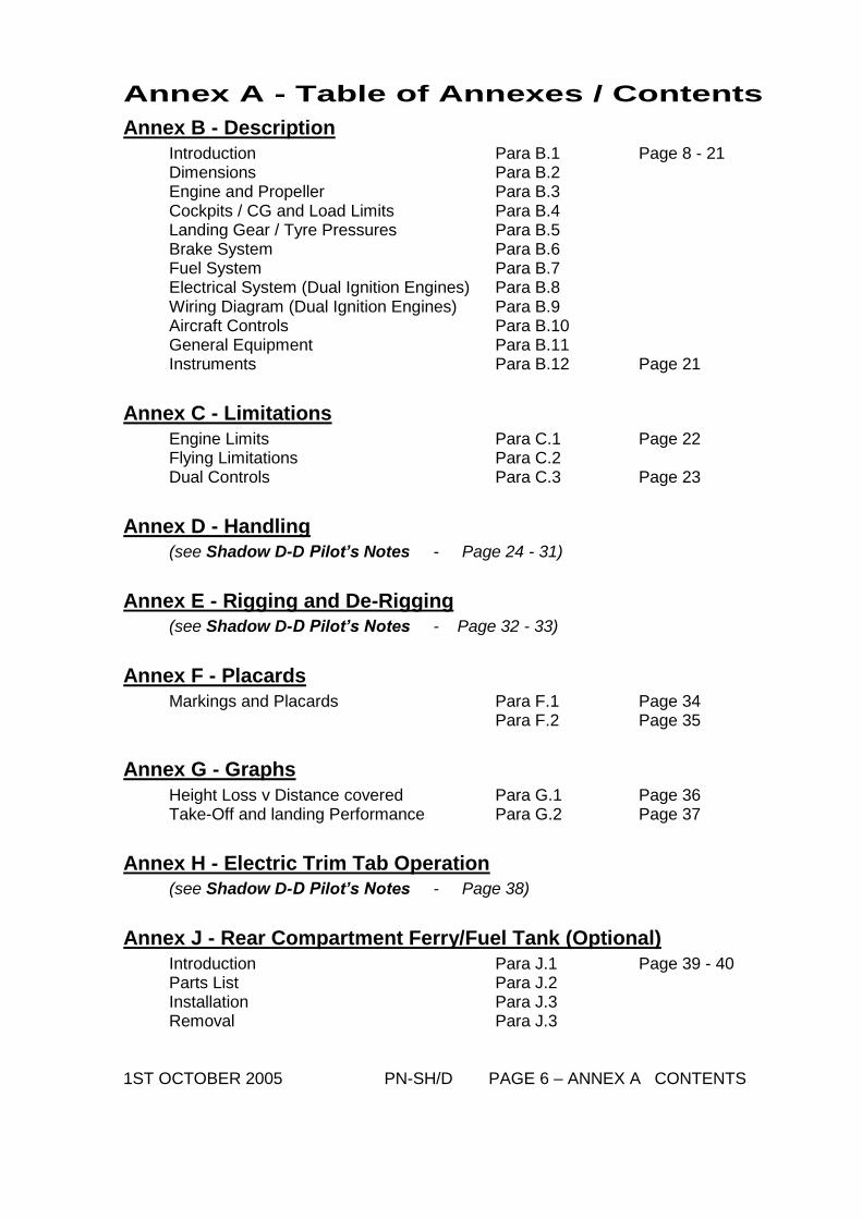
Annex A - Table of Annexes / Contents
Annex B - Description
Introduction Para B.1 Page 8 - 21 Dimensions Para B.2 Engine and Propeller Para B.3 Cockpits / CG and Load Limits Para B.4 Landing Gear / Tyre Pressures Para B.5 Brake System Para B.6 Fuel System Para B.7 Electrical System (Dual Ignition Engines) Para B.8 Wiring Diagram (Dual Ignition Engines) Para B.9 Aircraft Controls Para B.10 General Equipment Para B.11 Instruments Para B.12 Page 21
Annex C - Limitations
Engine Limits Para C.1 Page 22 Flying Limitations Para C.2 Dual Controls Para C.3 Page 23
Annex D - Handling
(see Shadow D-D Pilot’s Notes - Page 24 - 31)
Annex E - Rigging and De-Rigging
(see Shadow D-D Pilot’s Notes - Page 32 - 33)
Annex F - Placards
Markings and Placards Para F.1 Page 34 Para F.2 Page 35
Annex G - Graphs
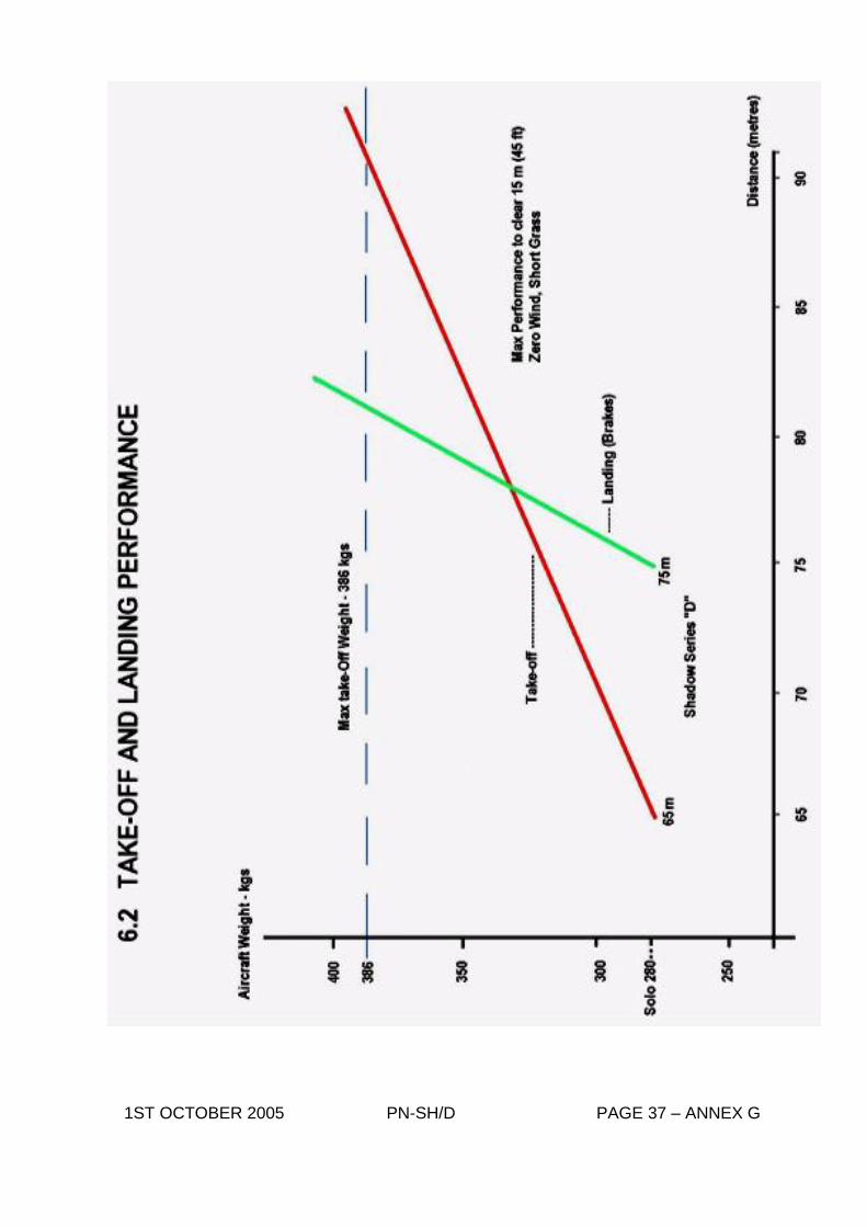
Height Loss v Distance covered Para G.1 Page 36 Take-Off and landing Performance Para G.2 Page 37
Annex H - Electric Trim Tab Operation
(see Shadow D-D Pilot’s Notes - Page 38)
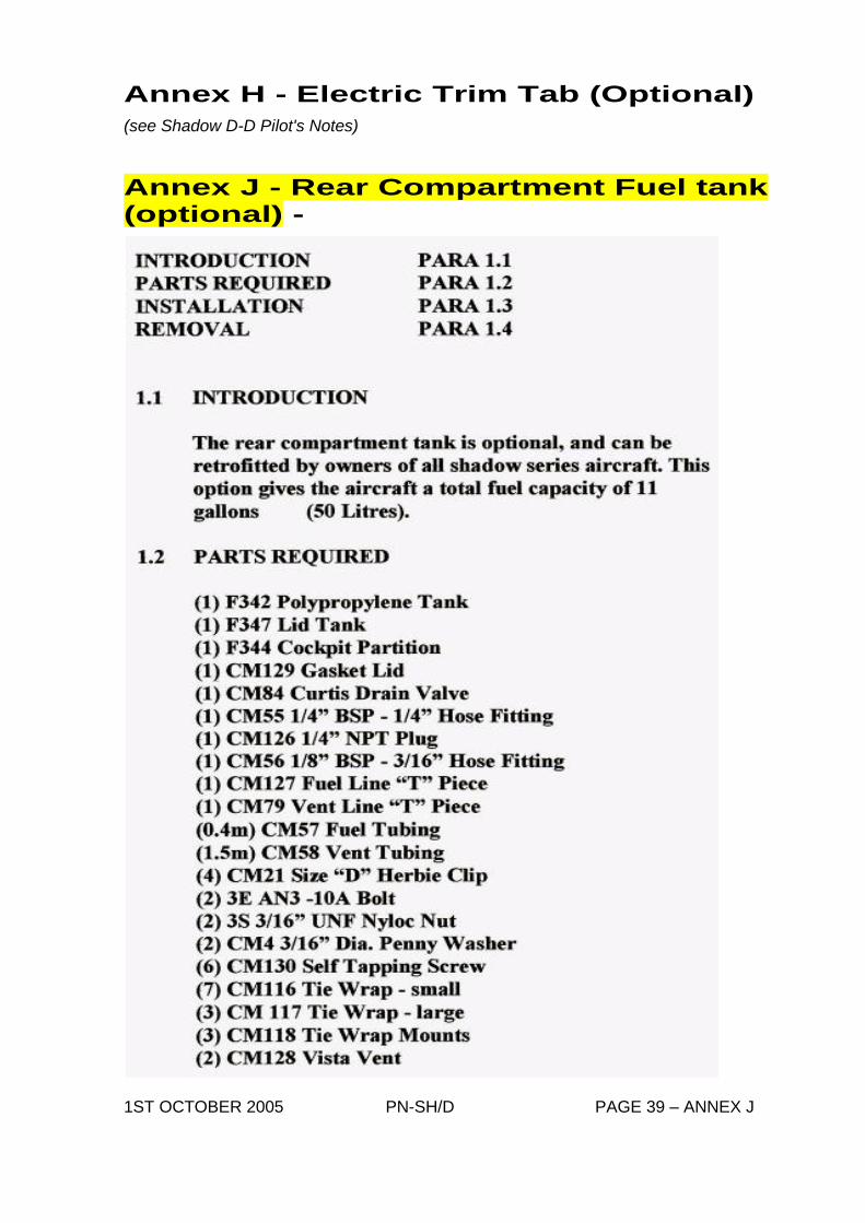
Annex J - Rear Compartment Ferry/Fuel Tank (Optional)
Introduction Para J.1 Page 39 - 40 Parts List Para J.2 Installation Para J.3 Removal Para J.3 1ST OCTOBER 2005 PN-SH/D PAGE 6 – ANNEX A CONTENTS
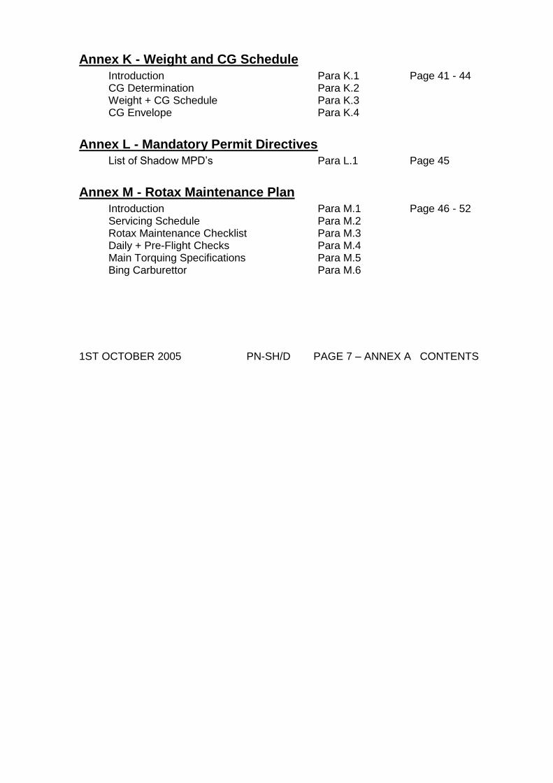
Annex K - Weight and CG Schedule
Introduction Para K.1 Page 41 - 44 CG Determination Para K.2 Weight + CG Schedule Para K.3 CG Envelope Para K.4
Annex L - Mandatory Permit Directives
List of Shadow MPD’s Para L.1 Page 45
Annex M - Rotax Maintenance Plan
Introduction Para M.1 Page 46 - 52 Servicing Schedule Para M.2 Rotax Maintenance Checklist Para M.3 Daily + Pre-Flight Checks Para M.4 Main Torquing Specifications Para M.5 Bing Carburettor Para M.6 1ST OCTOBER 2005 PN-SH/D PAGE 7 – ANNEX A CONTENTS
Annex B - Description
* NOTE: Unless otherwise stated, all AIRSPEEDS quoted are INDICATED airspeeds.
B.1 Introduction
The “SHADOW” Microlight Aircraft is a high-wing monoplane with conventional three-axis control, three position flaps and differential brakes on the main wheels.
B.2 Dimensions
Length – overall 21’ 0” 6405mm Height 8’ 2” 2490mm Wing Span 32”11” 10015mm Dihedral 0° Wing area 164 sq ft 15.26 m2 Tailplane area 14.2 sq ft 1.32 m2 Elevator area 9.2 sq ft 0.86 m2 Rudder area 4.3 sq ft 0.40 m2 Fin area 5.2 sq ft 0.48 m2 Aileron area 6.0 sq ft (x2) 0.56 m2 (x2) Flap area 5.6 sq ft (x2) 0.52 m2 (x2) Aspect Ratio 6.6 : 1 Wheel Track 4’9” 1450mm Wheel Base 6’0” 1830mm Wing Incidence 4° (Washout to 2° at wing tip)
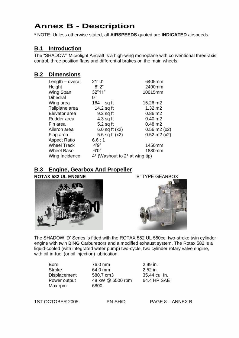
B.3 Engine, Gearbox And Propeller
ROTAX 582 UL ENGINE ‘B’ TYPE GEARBOX
The SHADOW ‘D’ Series is fitted with the ROTAX 582 UL 580cc, two-stroke twin cylinder engine with twin BING Carburettors and a modified exhaust system. The Rotax 582 is a liquid-cooled (with integrated water pump) two-cycle, two cylinder rotary valve engine, with oil-in-fuel (or oil injection) lubrication.
Bore 76.0 mm 2.99 in. Stroke 64.0 mm 2.52 in. Displacement 580.7 cm3 35.44 cu. In. Power output 48 kW @ 6500 rpm 64.4 HP SAE Max rpm 6800
1ST OCTOBER 2005 PN-SH/D PAGE 8 – ANNEX B
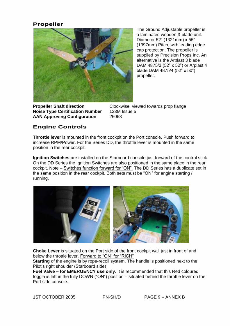
Propeller The Ground Adjustable propeller is a laminated wooden 3-blade unit. Diameter 52” (1321mm) x 55” (1397mm) Pitch, with leading edge cap protection. The propeller is supplied by Precision Props Inc. An alternative is the Arplast 3 blade DAM 4875/3 (52” x 52”) or Arplast 4 blade DAM 4875/4 (52” x 50”) propeller.
Propeller Shaft direction Clockwise, viewed towards prop flange Noise Type Certification Number 123M Issue 5 AAN Approving Configuration 26063
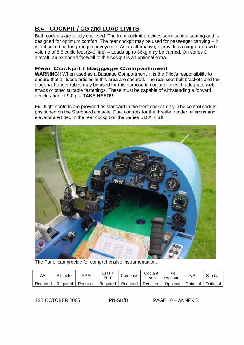
Engine Controls Throttle lever is mounted in the front cockpit on the Port console. Push forward to increase RPM/Power. For the Series DD, the throttle lever is mounted in the same position in the rear cockpit. Ignition Switches are installed on the Starboard console just forward of the control stick. On the DD Series the Ignition Switches are also positioned in the same place in the rear cockpit. Note – Switches function forward for “ON”. The DD Series has a duplicate set in the same position in the rear cockpit. Both sets must be “ON” for engine starting / running.
Choke Lever is situated on the Port side of the front cockpit wall just in front of and below the throttle lever. Forward to “ON” for “RICH” Starting of the engine is by rope-recoil system. The handle is positioned next to the Pilot’s right shoulder (Starboard side) Fuel Valve – for EMERGENCY use only. It is recommended that this Red coloured toggle is left in the fully DOWN (“ON”) position – situated behind the throttle lever on the Port side console. 1ST OCTOBER 2005 PN-SH/D PAGE 9 – ANNEX B
B.4 COCKPIT / CG and LOAD LIMITS
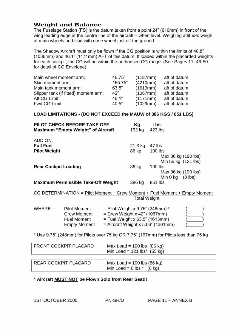
Both cockpits are totally enclosed. The front cockpit provides semi-supine seating and is designed for optimum comfort. The rear cockpit may be used for passenger carrying – it is not suited for long-range conveyance. As an alternative, it provides a cargo area with volume of 8.5 cubic feet (240 litre) – Loads up to 86kg may be carried. On series D aircraft, an extended footwell to this cockpit is an optional extra.
Rear Cockpit / Baggage Compartment WARNING!! When used as a Baggage Compartment, it is the Pilot’s responsibility to ensure that all loose articles in this area are secured. The rear seat belt brackets and the diagonal hanger tubes may be used for this purpose in conjunction with adequate web straps or other suitable fastenings. These must be capable of withstanding a forward acceleration of 9.0 g – TAKE HEED!! Full flight controls are provided as standard in the front cockpit only. The control stick is positioned on the Starboard console. Dual controls for the throttle, rudder, ailerons and elevator are fitted in the rear cockpit on the Series DD Aircraft.
The Panel can provide for comprehensive instrumentation.
ASI Altimeter RPM CHT / EGT
Compass Coolant
temp Fuel
Pressure VSI Slip ball
Required Required Required Required Required Required Optional Optional Optional
1ST OCTOBER 2005 PN-SH/D PAGE 10 – ANNEX B
Weight and Balance The Fuselage Station (FS) is the datum taken from a point 24” (610mm) in front of the wing leading edge at the centre line of the aircraft – when level. Weighing attitude: weigh at main wheels and skid with nose wheel just off the ground. The Shadow Aircraft must only be flown if the CG position is within the limits of 40.8” (1036mm) and 46.1” (1171mm) AFT of this datum. If loaded within the placarded weights for each cockpit, the CG will be within the authorised CG range. (See Pages 11, 46-50 for detail of CG Envelope). Main wheel moment arm; 46.75” (1187mm) aft of datum Skid moment arm; 165.75” (4210mm) aft of datum Main tank moment arm; 63.5” (1613mm) aft of datum Slipper tank (if fitted) moment arm; 42” (1067mm) aft of datum Aft CG Limit; 46.1” (1171mm) aft of datum Fwd CG Limit; 40.5” (1029mm) aft of datum LOAD LIMITATIONS - (DO NOT EXCEED the MAUW of 386 KGS / 851 LBS) PILOT CHECK BEFORE TAKE OFF Kg Lbs Maximum “Empty Weight” of Aircraft 192 kg 423 lbs ADD ON: Full Fuel 21.3 kg 47 lbs Pilot Weight 86 kg 190 lbs Max 86 kg (190 lbs) Min 55 kg (121 lbs) Rear Cockpit Loading 86 kg 190 lbs Max 86 kg (190 lbs) Min 0 kg (0 lbs) Maximum Permissible Take-Off Weight 386 kg 851 lbs CG DETERMINATION = Pilot Moment + Crew Moment + Fuel Moment + Empty Moment Total Weight WHERE: - Pilot Moment = Pilot Weight x 9.75” (248mm) * (______) Crew Moment = Crew Weight x 42” (1067mm) (______) Fuel Moment = Fuel Weight x 63.5” (1613mm) (______) Empty Moment = Aircraft Weight x 53.6” (1361mm) (______) * Use 9.75” (248mm) for Pilots over 75 kg OR 7.75” (197mm) for Pilots less than 75 kg
FRONT COCKPIT PLACARD Max Load = 190 lbs (86 kg) Min Load = 121 lbs* (55 kg)
REAR COCKPIT PLACARD Max Load = 190 lbs (86 kg) Min Load = 0 lbs * (0 kg)
* Aircraft MUST NOT be Flown Solo from Rear Seat!! 1ST OCTOBER 2005 PN-SH/D PAGE 11 – ANNEX B
B.5 Landing Gear / Tyre Pressures
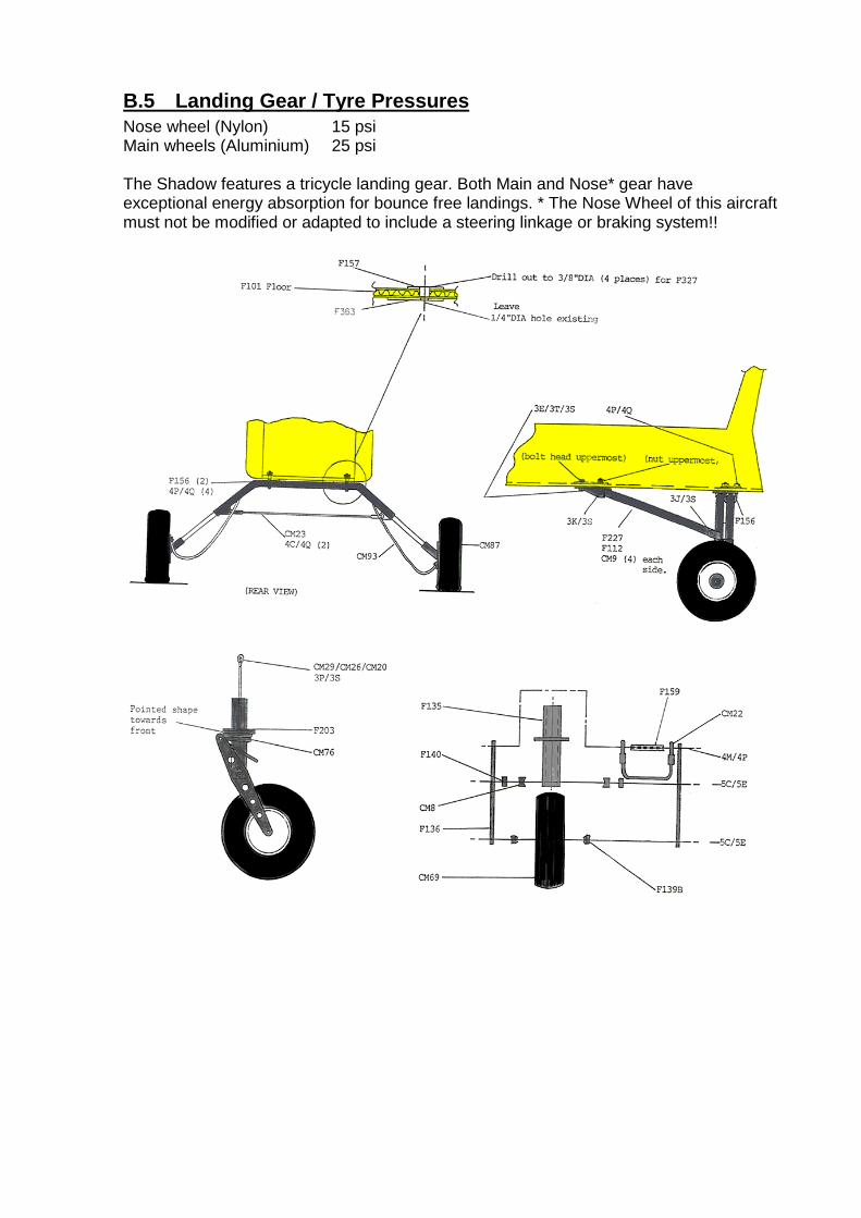
Nose wheel (Nylon) 15 psi Main wheels (Aluminium) 25 psi The Shadow features a tricycle landing gear. Both Main and Nose* gear have exceptional energy absorption for bounce free landings. * The Nose Wheel of this aircraft must not be modified or adapted to include a steering linkage or braking system!!
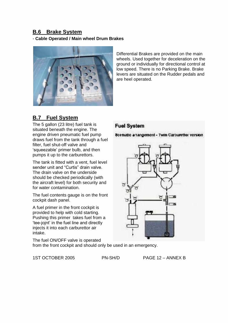
B.6 Brake System
- Cable Operated / Main wheel Drum Brakes Differential Brakes are provided on the main wheels. Used together for deceleration on the ground or individually for directional control at low speed. There is no Parking Brake. Brake levers are situated on the Rudder pedals and are heel operated.
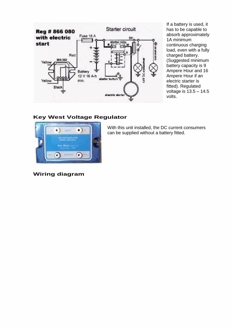
B.7 Fuel System
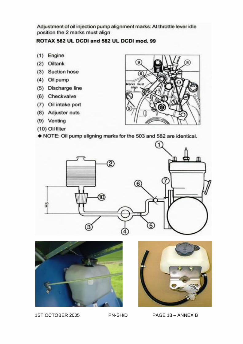
The 5 gallon (23 litre) fuel tank is
situated beneath the engine. The engine driven pneumatic fuel pump draws fuel from the tank through a fuel filter, fuel shut-off valve and ‘squeezable’ primer bulb, and then pumps it up to the carburettors.
The tank is fitted with a vent, fuel level sender unit and “Curtis” drain valve. The drain valve on the underside should be checked periodically (with the aircraft level) for both security and for water contamination.
The fuel contents gauge is on the front cockpit dash panel.
A fuel primer in the front cockpit is provided to help with cold starting. Pushing this primer takes fuel from a ‘tee-jojnt’ in the fuel line and directly injects it into each carburettor air intake.
The fuel ON/OFF valve is operated from the front cockpit and should only be used in an emergency.
1ST OCTOBER 2005 PN-SH/D PAGE 12 – ANNEX B

Use AVGAS (with permission to use Unleaded MOGAS – see Notes in Aircraft/Engine Log Book). Fuel/Oil mixture ratio is 50:1 (2–stroke oil Castrol TTS / Aviation 545LA recommended)
Fuel Tank Cap, uplift Pump, Bulb and Primer are mounted on Starboard side of Engine below twin carbs.
B.8 Electrical System (Dual Ignition Engines)
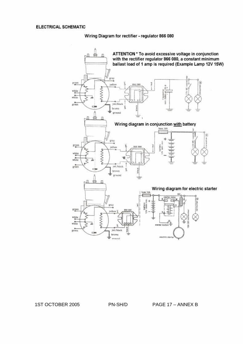
Lighting Circuit Eight Lighting Coils are incorporated in the Stator. The output is 170W AC and 13.5V, effective at 6000 rpm. This alternating current can be used directly to feed AC consumers (e.g. strobes), or via a rectifier / regulator for loading a battery and feeding direct current consumers. There should be an in line fuse of 16 amps rating in the system A Voltage regulator must be used to avoid the voltage rising above permissible levels. To operate the loads requiring direct current (e.g. charging battery), a rectifier – regulator is required.
A rectifier – regulator (part number 866-080) is available. For feeding lights only, this rectifier – regulator can also be used without the battery. In this case, the RMS voltage will be between 11 and 12 volts, as long as a minimum load demanding 1 Amp is provided.
1ST OCTOBER 2005 PN-SH/D PAGE 13 – ANNEX B
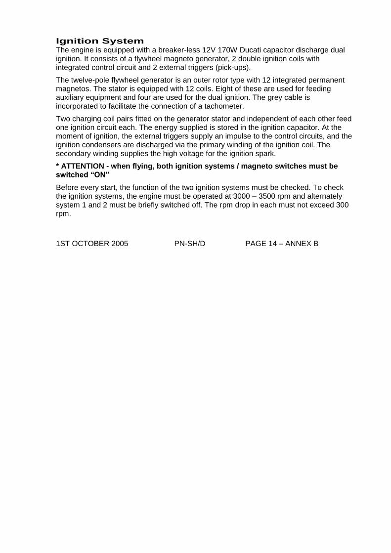
If a battery is used, it has to be capable to absorb approximately 1A minimum continuous charging load, even with a fully charged battery. (Suggested minimum battery capacity is 9 Ampere Hour and 16 Ampere Hour if an electric starter is fitted). Regulated voltage is 13.5 – 14.5 volts.
Key West Voltage Regulator With this unit installed, the DC current consumers can be supplied without a battery fitted.
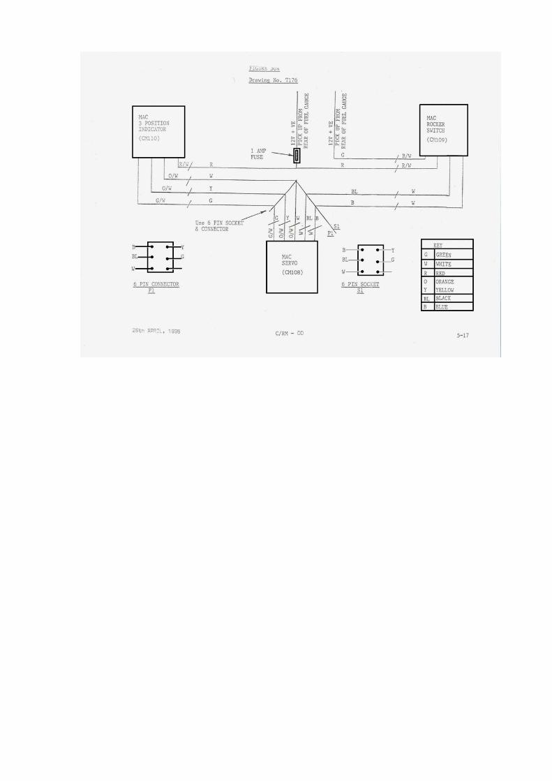
Wiring diagram

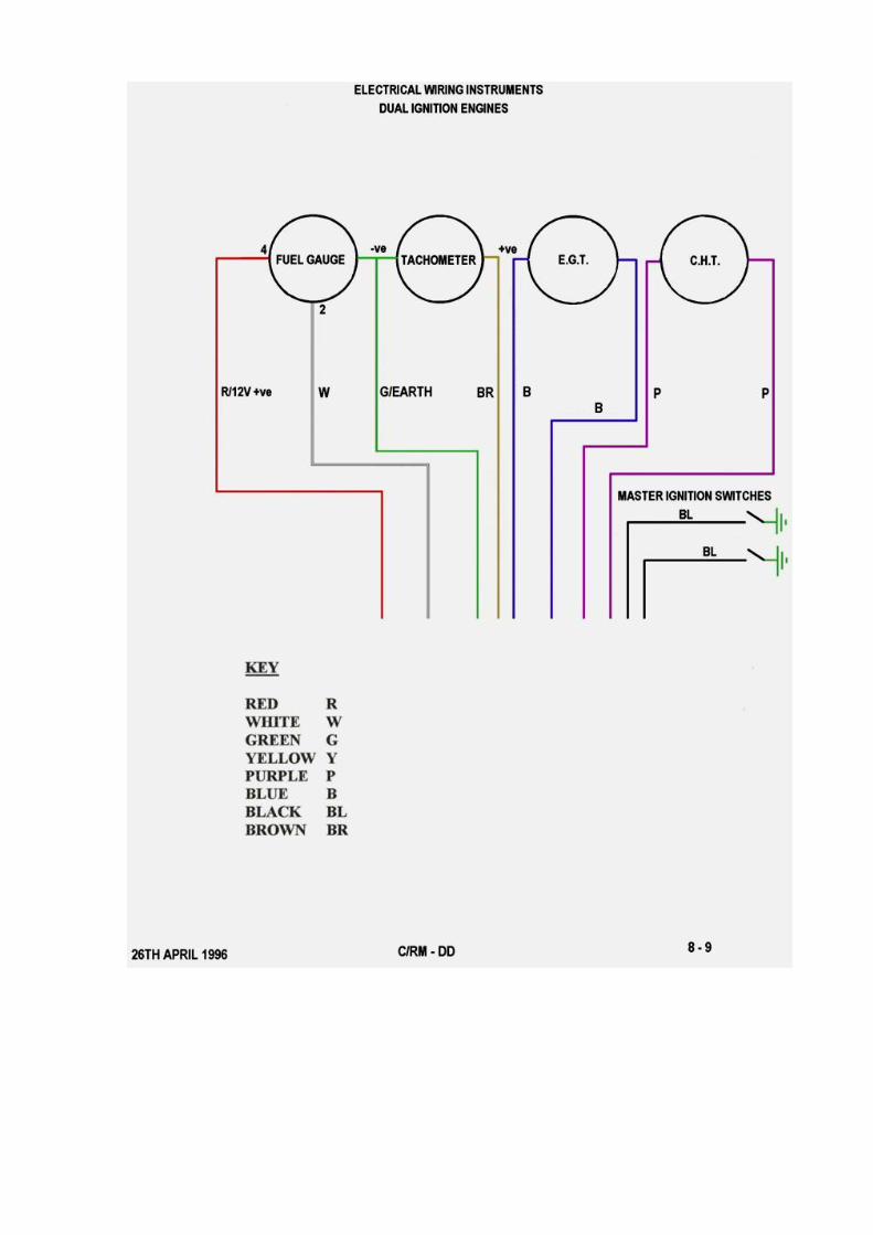
Instrument wiring diagram
Ignition System The engine is equipped with a breaker-less 12V 170W Ducati capacitor discharge dual ignition. It consists of a flywheel magneto generator, 2 double ignition coils with integrated control circuit and 2 external triggers (pick-ups).
The twelve-pole flywheel generator is an outer rotor type with 12 integrated permanent magnetos. The stator is equipped with 12 coils. Eight of these are used for feeding auxiliary equipment and four are used for the dual ignition. The grey cable is incorporated to facilitate the connection of a tachometer.
Two charging coil pairs fitted on the generator stator and independent of each other feed one ignition circuit each. The energy supplied is stored in the ignition capacitor. At the moment of ignition, the external triggers supply an impulse to the control circuits, and the ignition condensers are discharged via the primary winding of the ignition coil. The secondary winding supplies the high voltage for the ignition spark.
* ATTENTION - when flying, both ignition systems / magneto switches must be switched “ON”
Before every start, the function of the two ignition systems must be checked. To check the ignition systems, the engine must be operated at 3000 – 3500 rpm and alternately system 1 and 2 must be briefly switched off. The rpm drop in each must not exceed 300 rpm.
1ST OCTOBER 2005 PN-SH/D PAGE 14 – ANNEX B
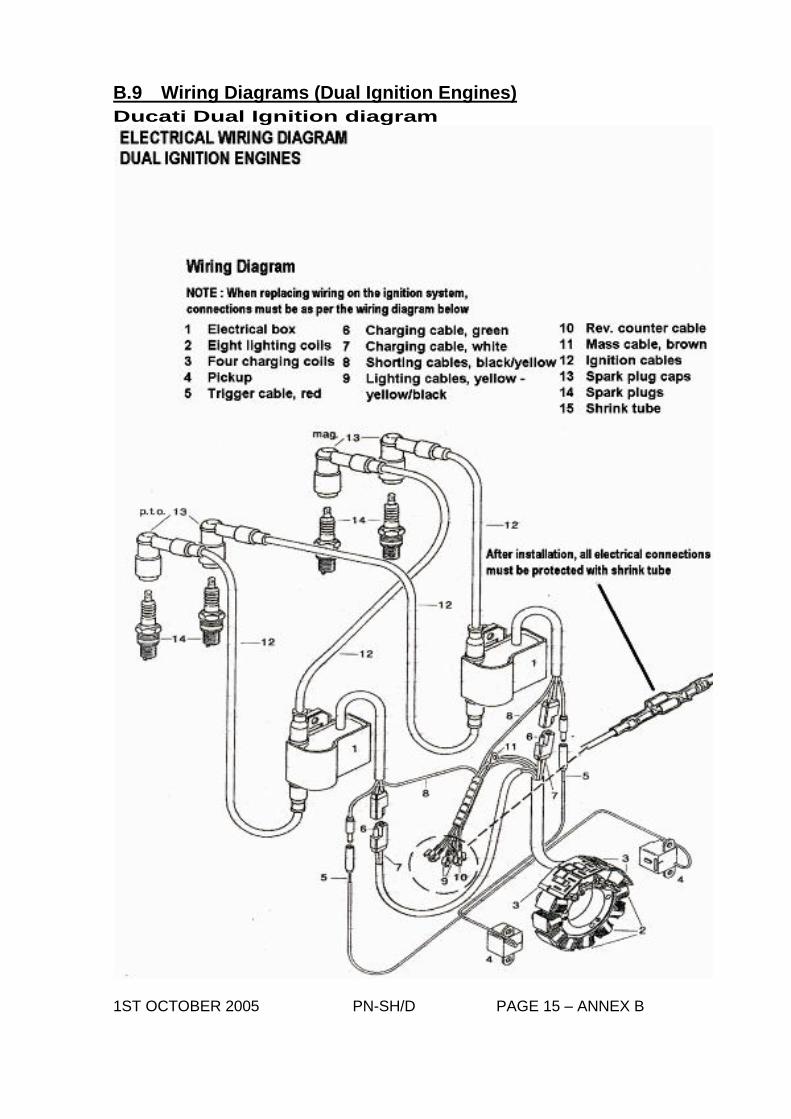
B.9 Wiring Diagrams (Dual Ignition Engines)
Ducati Dual Ignition diagram
1ST OCTOBER 2005 PN-SH/D PAGE 15 – ANNEX B
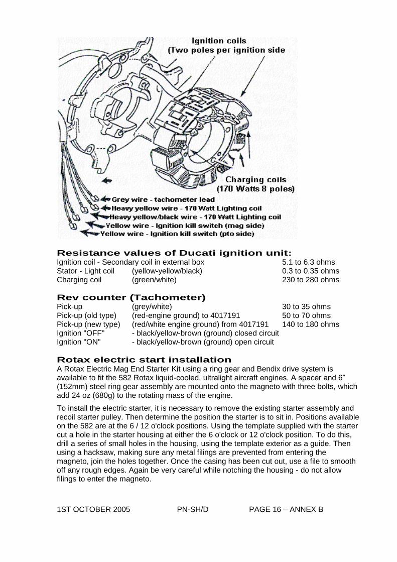
Resistance values of Ducati ignition unit: Ignition coil - Secondary coil in external box 5.1 to 6.3 ohms Stator - Light coil (yellow-yellow/black) 0.3 to 0.35 ohms Charging coil (green/white) 230 to 280 ohms
Rev counter (Tachometer) Pick-up (grey/white) 30 to 35 ohms Pick-up (old type) (red-engine ground) to 4017191 50 to 70 ohms Pick-up (new type) (red/white engine ground) from 4017191 140 to 180 ohms Ignition "OFF" - black/yellow-brown (ground) closed circuit Ignition "ON" - black/yellow-brown (ground) open circuit
Rotax electric start installation A Rotax Electric Mag End Starter Kit using a ring gear and Bendix drive system is available to fit the 582 Rotax liquid-cooled, ultralight aircraft engines. A spacer and 6” (152mm) steel ring gear assembly are mounted onto the magneto with three bolts, which add 24 oz (680g) to the rotating mass of the engine.
To install the electric starter, it is necessary to remove the existing starter assembly and recoil starter pulley. Then determine the position the starter is to sit in. Positions available on the 582 are at the 6 / 12 o'clock positions. Using the template supplied with the starter cut a hole in the starter housing at either the 6 o'clock or 12 o'clock position. To do this, drill a series of small holes in the housing, using the template exterior as a guide. Then using a hacksaw, making sure any metal filings are prevented from entering the magneto, join the holes together. Once the casing has been cut out, use a file to smooth off any rough edges. Again be very careful while notching the housing - do not allow filings to enter the magneto.
1ST OCTOBER 2005 PN-SH/D PAGE 16 – ANNEX B
1ST OCTOBER 2005 PN-SH/D PAGE 17 – ANNEX B
1ST OCTOBER 2005 PN-SH/D PAGE 18 – ANNEX B

Electrical Ancillaries
Wiring Electronic box (ignition circuit 1) Electronic box (ignition circuit 2) eight lighting coils four charging coils Pickup (ignition circuit 1) trigger cable red charging cable green charging cable white Shorting cables black/yellow Shorting cables black/yellow lighting cables yellow-yellow/black tachometer cable grey mass cable brown ignition cables sparkplug connectors spark plugs shrink wrap tube
With the engine running the trigger cable (Red) MUST NOT be disconnected from the electronic box. This could destroy the electronics in the box. 1ST OCTOBER 2005 PN-SH/D PAGE 19 – ANNEX B
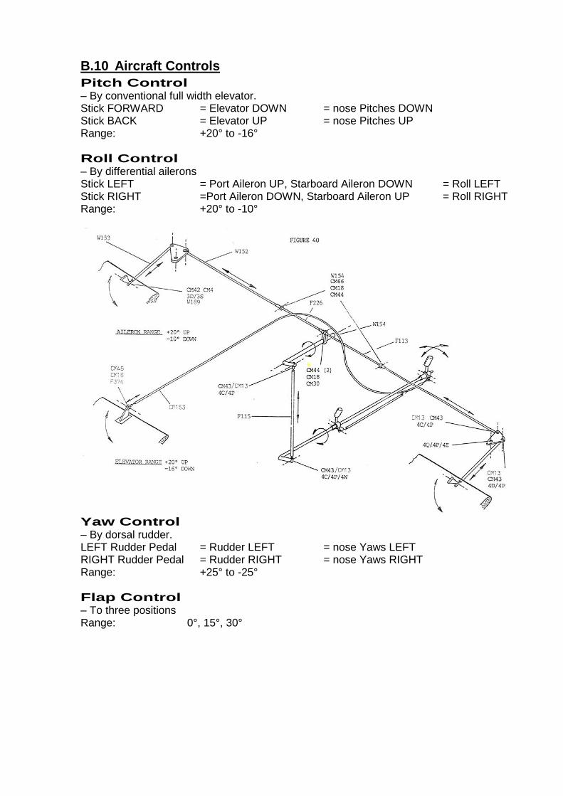
B.10 Aircraft Controls
Pitch Control – By conventional full width elevator. Stick FORWARD = Elevator DOWN = nose Pitches DOWN Stick BACK = Elevator UP = nose Pitches UP Range: +20° to -16°
Roll Control – By differential ailerons Stick LEFT = Port Aileron UP, Starboard Aileron DOWN = Roll LEFT Stick RIGHT =Port Aileron DOWN, Starboard Aileron UP = Roll RIGHT Range: +20° to -10°
Yaw Control – By dorsal rudder. LEFT Rudder Pedal = Rudder LEFT = nose Yaws LEFT RIGHT Rudder Pedal = Rudder RIGHT = nose Yaws RIGHT Range: +25° to -25°
Flap Control – To three positions Range: 0°, 15°, 30°
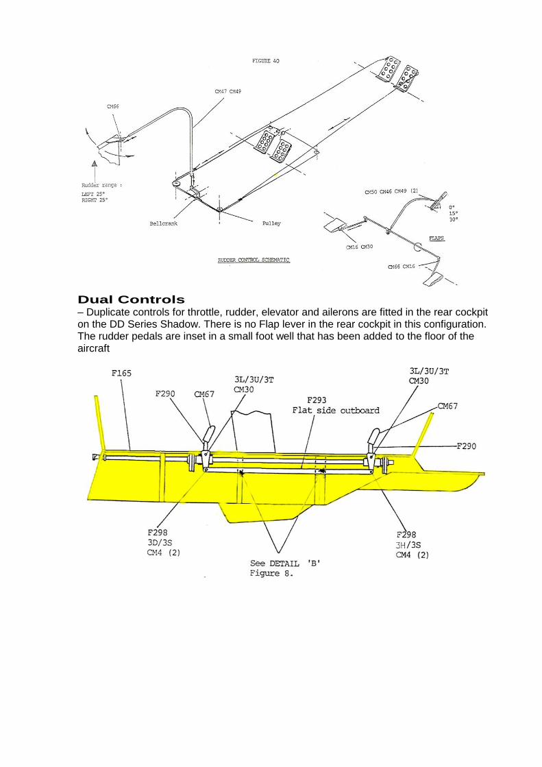
Dual Controls – Duplicate controls for throttle, rudder, elevator and ailerons are fitted in the rear cockpit on the DD Series Shadow. There is no Flap lever in the rear cockpit in this configuration. The rudder pedals are inset in a small foot well that has been added to the floor of the aircraft
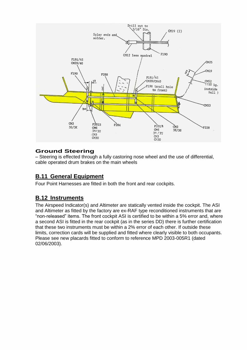
Ground Steering – Steering is effected through a fully castoring nose wheel and the use of differential, cable operated drum brakes on the main wheels
B.11 General Equipment
Four Point Harnesses are fitted in both the front and rear cockpits.
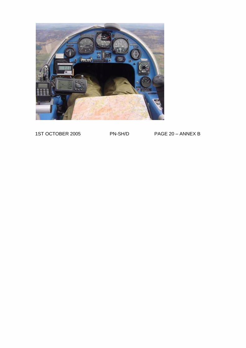
B.12 Instruments
The Airspeed Indicator(s) and Altimeter are statically vented inside the cockpit. The ASI and Altimeter as fitted by the factory are ex-RAF type reconditioned instruments that are “non-released” items. The front cockpit ASI is certified to be within a 5% error and, where a second ASI is fitted in the rear cockpit (as in the series DD) there is further certification that these two instruments must be within a 2% error of each other. If outside these limits, correction cards will be supplied and fitted where clearly visible to both occupants. Please see new placards fitted to conform to reference MPD 2003-005R1 (dated 02/06/2003).
1ST OCTOBER 2005 PN-SH/D PAGE 20 – ANNEX B
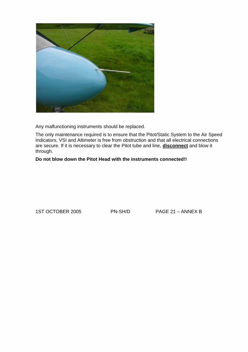
Any malfunctioning instruments should be replaced.
The only maintenance required is to ensure that the Pitot/Static System to the Air Speed Indicators, VSI and Altimeter is free from obstruction and that all electrical connections are secure. If it is necessary to clear the Pitot tube and line, disconnect and blow it through.
Do not blow down the Pitot Head with the instruments connected!!
1ST OCTOBER 2005 PN-SH/D PAGE 21 – ANNEX B
Annex C – Limitations
C.1 Engine Limits
Minimum RPM 2000 rpm Maximum RPM 6500 rpm Maximum Continuous RPM 6000 rpm
EGT - Exhaust Gas Temperatures Normal: 500° C - 620° C (930° F - 1150° F) Max difference between cylinders 25° C (45° F) Maximum EGT 650°C (1200°F) Maximum Coolant Temp 80°C (175°F) Maximum Crankcase Temp 80°C (175°F)
CHT - Cylinder Head Temperatures Normal: 110° C - 130° C (230° F - 270° F) Maximum: 150° C (300° F) Max. Difference: 10° C (45° F)
Air Temperature Corrections These indicators / gauges are calibrated at 70°F (21°C) standard and read the difference between the thermocouple prod or ring and pin terminals (air temperature) on cable. For air temperatures below 70°F the correct reading would be the gauge reading minus the number of degrees that the air temperature is below 70°F. For air temperatures above 70°F, add that amount to the gauge reading.
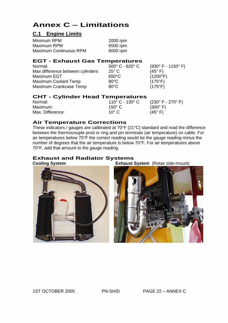
Exhaust and Radiator Systems Cooling System Exhaust System (Rotax side-mount)
1ST OCTOBER 2005 PN-SH/D PAGE 22 – ANNEX C
C.2 Flying Limitations
Control movements are to be restricted to 1/3 deflection at speeds in excess of Va (70 kts / 80mph) Vne (never exceed speed) 108 kts (= 124mph) 198 kmph Vfe (max flap extend speed) 15° 61 kts (= 70mph) 30° 59 kts (= 68mph) Va (Design manoeuvre speed) 70 kts (= 80mph) 129 kmph Vso 30-35 kts IAS (= 35–40 mph) 55–64 kmph Stall (or minimum flying) Speed: 35 kts (= 40 mph) 64 kmph Rate-of-Climb: 850 ft/min @ 60 KIAS Ceiling 10,000 feet (without oxygen) Operation VFR (Daytime only) Maximum Wing Loading: 25 kg/m2 Permitted Manoeuvres 45° Nose UP / 60° nose DOWN 60° Maximum bank angle +4 / -2g Normal acceleration limits Aerobatics and Spinning prohibited
C 3 Dual Controls
– * Do not attempt to fly the aircraft solo from the rear cockpit. REPEAT - *AIRCRAFT MUST NOT BE FLOWN SOLO FROM REAR SEAT!!
Annex D - Handling
(see Shadow series D-D Pilot's Notes - Pages 24-31) Covers:
Pre-Flight Checklist
Engine Start
Taxying
Take-Off
Climb
General Flying
Range and Endurance
Stalls
Turns
Spinning + Aerobatics
Side Slipping
Pre-Landing Checks
Approach and Landing
Going Around
Stopping the Engine
Engine Failure
Fire
Flying from the Rear Cockpit – Dual Controls
Annex E - Rigging and De-Rigging
(see Shadow D-D Pilot's Notes - Pages 32-33) 1ST OCTOBER 2005 PN-SH/D PAGE 23
Annex F - Markings and Placards
F.1 Markings and Placards
Vne = Never Exceed Speed 108 kts (= 124 mph or 200 km/h)
Vfe = Flaps Maximum Operating Speed:- 15° Flap 61 kts (= 70 mph or 113 km/h) 30° Flap 59 kts (= 68 mph or 110 km/h
Engine Limitations Placard (located near to engine instruments)
‘Max EGT 1200°F (= 650°C)’ ‘Max CHT 300°F (= 150°C)’ ‘Max Coolant Temp 203°F (= 95°C)’ ‘Max RPM 6500 for 3 mins’
‘Throttle “INCREASE “ “DECREASE”
‘Ignition “ON “ “OFF”
‘Choke “ON’ ‘Choke “OFF’
Fuel Limitations Placard (to be located near to Filler Cap)
Usable Fuel Capacity …………….Imp Gals…………….Ltrs MAIN FUEL TANK Capacity…………... Imp gals……..…..Ltrs Oil 2-stroke mix: 50:1 Fuel grade: PREMIUM
SLIPPER FUEL TANK (If Fitted) Capacity …………...Imp Gals …………Ltrs Oil 2-Stroke Mix: 50:1 Fuel Grade: PREMIUM
‘Emergency Fuel Cut Off – UP for OFF’
‘FUSE 1 AMP’
1ST OCTOBER 2005 PN-SH/D PAGE 34 – ANNEX F
F.2 Markings and Placards (contd)
‘Trim’ ‘Nose Up’ ‘Take-off’ ‘Nose Down’
‘Spinning PROHIBITED’ ‘Aerobatics PROHIBITED’
Maximum Empty Weight must be placarded.
‘Maximum AUW 386 kg (= 851 lb)’ ‘Max LOAD (Front Cockpit) 86 kg (= 190 lb); MIN LOAD 55 kg (= 121 lb)’ ‘Max LOAD (Rear Cockpit) 86 kg (= 190 lb); MIN LOAD 0 kg (= 0 lb)’
CG Limits and Datum to be placarded.
“AFT CG“ “DATUM“ “ FWD CG“
Manufacturer’s Identity Plate (steel)
‘Emergency Glide Procedure: Speed 50 kts (= 57 mph or 92 km/h Glide Ratio: 2.5mls/1000ft AGL’
WARNINGS ‘Do NOT Get Out when Engine is Running’ ‘Do NOT attempt to Fly the Aircraft Solo from the Rear Seat’ ‘No Baggage or Other Loads Permitted in Rear Cockpit when this Tank is installed’
1ST OCTOBER 2005 PN-SH/D PAGE 35 – ANNEX F
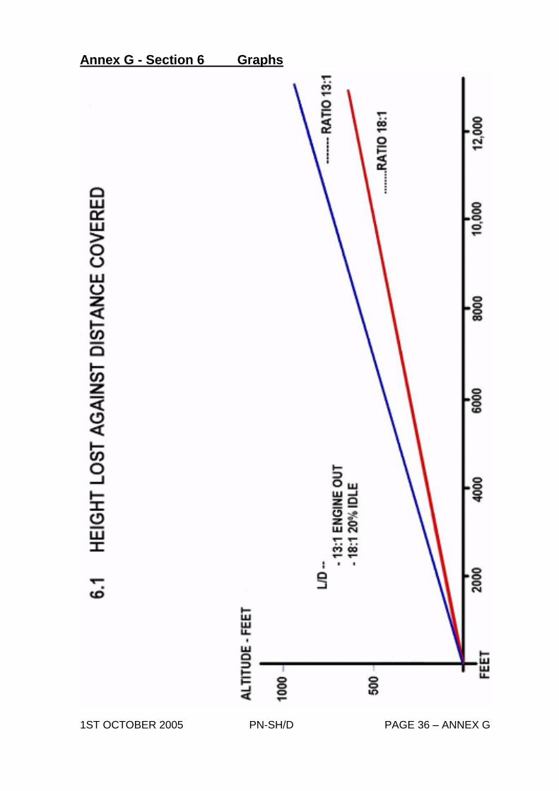
Annex G - Section 6 Graphs
1ST OCTOBER 2005 PN-SH/D PAGE 36 – ANNEX G
1ST OCTOBER 2005 PN-SH/D PAGE 37 – ANNEX G
Annex H - Electric Trim Tab (Optional)
(see Shadow D-D Pilot's Notes)
Annex J - Rear Compartment Fuel tank (optional) -
1ST OCTOBER 2005 PN-SH/D PAGE 39 – ANNEX J
1ST OCTOBER 2005 PN-SH/D PAGE 40 – ANNEX J
Annex K - Weight and CG Schedule
K.1 Introduction
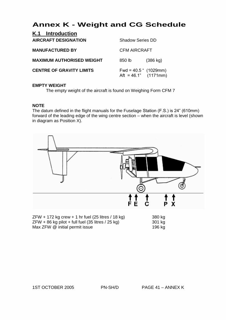
AIRCRAFT DESIGNATION Shadow Series DD MANUFACTURED BY CFM AIRCRAFT MAXIMUM AUTHORISED WEIGHT 850 lb (386 kg) CENTRE OF GRAVITY LIMITS Fwd = 40.5 “ (1029mm) Aft = 46.1” (1171mm) EMPTY WEIGHT The empty weight of the aircraft is found on Weighing Form CFM 7 NOTE The datum defined in the flight manuals for the Fuselage Station (F.S.) is 24” (610mm) forward of the leading edge of the wing centre section – when the aircraft is level (shown in diagram as Position X).
ZFW + 172 kg crew + 1 hr fuel (25 litres / 18 kg) 380 kg ZFW + 86 kg pilot + full fuel (35 litres / 25 kg) 301 kg Max ZFW @ initial permit issue 196 kg 1ST OCTOBER 2005 PN-SH/D PAGE 41 – ANNEX K
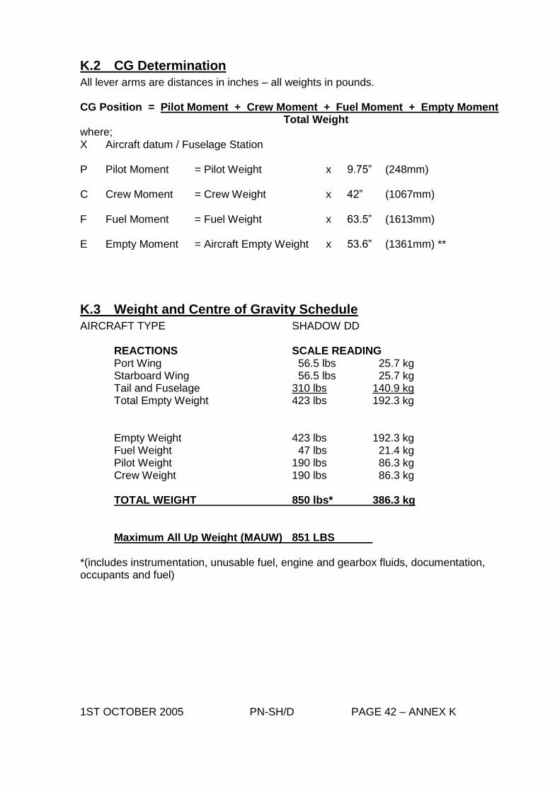
K.2 CG Determination
All lever arms are distances in inches – all weights in pounds. CG Position = Pilot Moment + Crew Moment + Fuel Moment + Empty Moment Total Weight where; X Aircraft datum / Fuselage Station P Pilot Moment = Pilot Weight x 9.75” (248mm) C Crew Moment = Crew Weight x 42” (1067mm) F Fuel Moment = Fuel Weight x 63.5” (1613mm) E Empty Moment = Aircraft Empty Weight x 53.6” (1361mm) **
K.3 Weight and Centre of Gravity Schedule
AIRCRAFT TYPE SHADOW DD
REACTIONS SCALE READING Port Wing 56.5 lbs 25.7 kg Starboard Wing 56.5 lbs 25.7 kg Tail and Fuselage 310 lbs 140.9 kg Total Empty Weight 423 lbs 192.3 kg Empty Weight 423 lbs 192.3 kg Fuel Weight 47 lbs 21.4 kg Pilot Weight 190 lbs 86.3 kg Crew Weight 190 lbs 86.3 kg TOTAL WEIGHT 850 lbs* 386.3 kg
Maximum All Up Weight (MAUW) 851 LBS
*(includes instrumentation, unusable fuel, engine and gearbox fluids, documentation, occupants and fuel) 1ST OCTOBER 2005 PN-SH/D PAGE 42 – ANNEX K
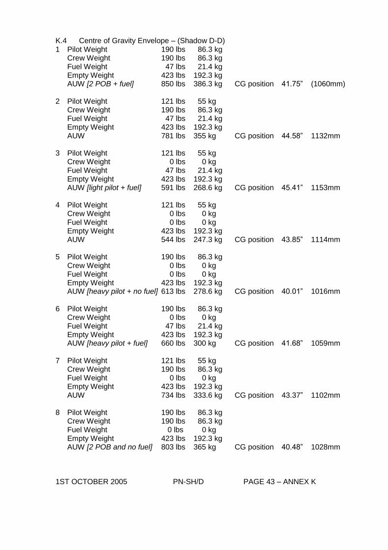
K.4 Centre of Gravity Envelope – (Shadow D-D) 1 Pilot Weight 190 lbs 86.3 kg Crew Weight 190 lbs 86.3 kg Fuel Weight 47 lbs 21.4 kg Empty Weight 423 lbs 192.3 kg AUW [2 POB + fuel] 850 lbs 386.3 kg CG position 41.75” (1060mm) 2 Pilot Weight 121 lbs 55 kg Crew Weight 190 lbs 86.3 kg Fuel Weight 47 lbs 21.4 kg Empty Weight 423 lbs 192.3 kg AUW 781 lbs 355 kg CG position 44.58” 1132mm 3 Pilot Weight 121 lbs 55 kg Crew Weight 0 lbs 0 kg Fuel Weight 47 lbs 21.4 kg Empty Weight 423 lbs 192.3 kg AUW [light pilot + fuel] 591 lbs 268.6 kg CG position 45.41” 1153mm 4 Pilot Weight 121 lbs 55 kg Crew Weight 0 lbs 0 kg Fuel Weight 0 lbs 0 kg Empty Weight 423 lbs 192.3 kg AUW 544 lbs 247.3 kg CG position 43.85” 1114mm 5 Pilot Weight 190 lbs 86.3 kg Crew Weight 0 lbs 0 kg Fuel Weight 0 lbs 0 kg Empty Weight 423 lbs 192.3 kg AUW [heavy pilot + no fuel] 613 lbs 278.6 kg CG position 40.01” 1016mm 6 Pilot Weight 190 lbs 86.3 kg Crew Weight 0 lbs 0 kg Fuel Weight 47 lbs 21.4 kg Empty Weight 423 lbs 192.3 kg AUW [heavy pilot + fuel] 660 lbs 300 kg CG position 41.68” 1059mm 7 Pilot Weight 121 lbs 55 kg Crew Weight 190 lbs 86.3 kg Fuel Weight 0 lbs 0 kg Empty Weight 423 lbs 192.3 kg AUW 734 lbs 333.6 kg CG position 43.37” 1102mm 8 Pilot Weight 190 lbs 86.3 kg Crew Weight 190 lbs 86.3 kg Fuel Weight 0 lbs 0 kg Empty Weight 423 lbs 192.3 kg AUW [2 POB and no fuel] 803 lbs 365 kg CG position 40.48” 1028mm 1ST OCTOBER 2005 PN-SH/D PAGE 43 – ANNEX K
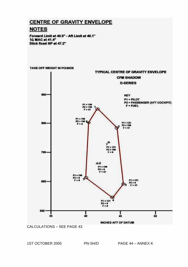
CALCULATIONS – SEE PAGE 43 1ST OCTOBER 2005 PN-SH/D PAGE 44 – ANNEX K
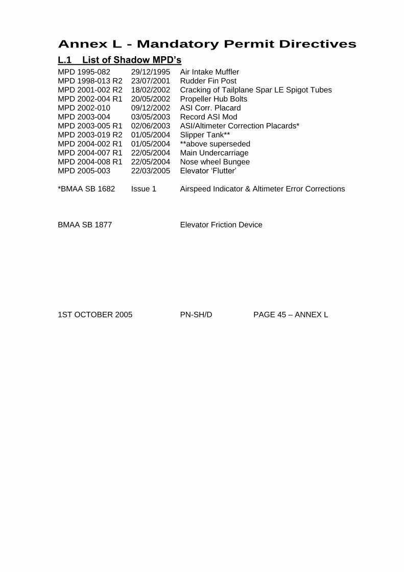
Annex L - Mandatory Permit Directives
L.1 List of Shadow MPD’s
MPD 1995-082 29/12/1995 Air Intake Muffler MPD 1998-013 R2 23/07/2001 Rudder Fin Post MPD 2001-002 R2 18/02/2002 Cracking of Tailplane Spar LE Spigot Tubes MPD 2002-004 R1 20/05/2002 Propeller Hub Bolts MPD 2002-010 09/12/2002 ASI Corr. Placard MPD 2003-004 03/05/2003 Record ASI Mod MPD 2003-005 R1 02/06/2003 ASI/Altimeter Correction Placards* MPD 2003-019 R2 01/05/2004 Slipper Tank** MPD 2004-002 R1 01/05/2004 **above superseded MPD 2004-007 R1 22/05/2004 Main Undercarriage MPD 2004-008 R1 22/05/2004 Nose wheel Bungee MPD 2005-003 22/03/2005 Elevator ‘Flutter’ *BMAA SB 1682 Issue 1 Airspeed Indicator & Altimeter Error Corrections BMAA SB 1877 Elevator Friction Device 1ST OCTOBER 2005 PN-SH/D PAGE 45 – ANNEX L
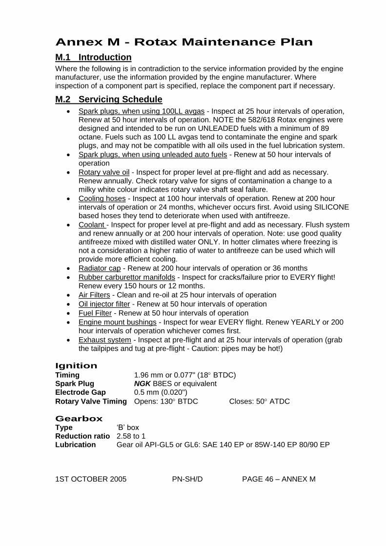
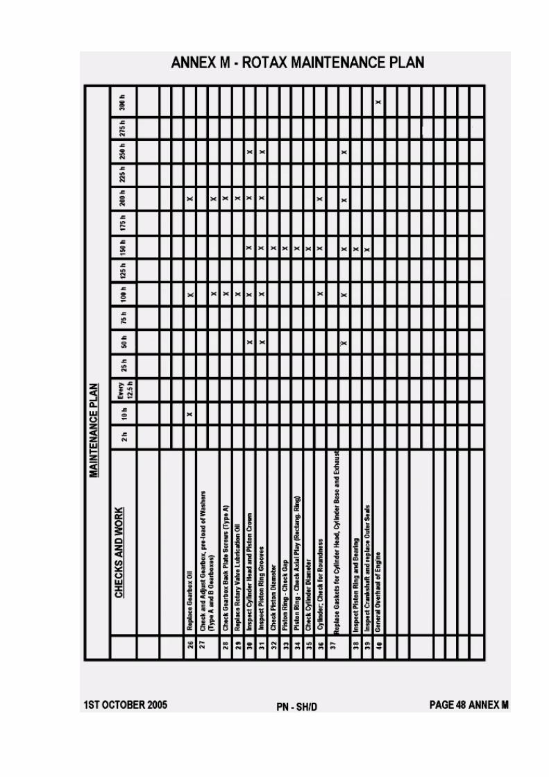
Annex M - Rotax Maintenance Plan
M.1 Introduction
Where the following is in contradiction to the service information provided by the engine manufacturer, use the information provided by the engine manufacturer. Where inspection of a component part is specified, replace the component part if necessary.
M.2 Servicing Schedule
Spark plugs, when using 100LL avgas - Inspect at 25 hour intervals of operation, Renew at 50 hour intervals of operation. NOTE the 582/618 Rotax engines were designed and intended to be run on UNLEADED fuels with a minimum of 89 octane. Fuels such as 100 LL avgas tend to contaminate the engine and spark plugs, and may not be compatible with all oils used in the fuel lubrication system.
Spark plugs, when using unleaded auto fuels - Renew at 50 hour intervals of operation
Rotary valve oil - Inspect for proper level at pre-flight and add as necessary. Renew annually. Check rotary valve for signs of contamination a change to a milky white colour indicates rotary valve shaft seal failure.
Cooling hoses - Inspect at 100 hour intervals of operation. Renew at 200 hour intervals of operation or 24 months, whichever occurs first. Avoid using SILICONE based hoses they tend to deteriorate when used with antifreeze.
Coolant - Inspect for proper level at pre-flight and add as necessary. Flush system and renew annually or at 200 hour intervals of operation. Note: use good quality antifreeze mixed with distilled water ONLY. In hotter climates where freezing is not a consideration a higher ratio of water to antifreeze can be used which will provide more efficient cooling.
Radiator cap - Renew at 200 hour intervals of operation or 36 months
Rubber carburettor manifolds - Inspect for cracks/failure prior to EVERY flight! Renew every 150 hours or 12 months.
Air Filters - Clean and re-oil at 25 hour intervals of operation
Oil injector filter - Renew at 50 hour intervals of operation
Fuel Filter - Renew at 50 hour intervals of operation
Engine mount bushings - Inspect for wear EVERY flight. Renew YEARLY or 200 hour intervals of operation whichever comes first.
Exhaust system - Inspect at pre-flight and at 25 hour intervals of operation (grab the tailpipes and tug at pre-flight - Caution: pipes may be hot!)
Ignition
Timing 1.96 mm or 0.077" (18 BTDC) Spark Plug NGK B8ES or equivalent Electrode Gap 0.5 mm (0.020")
Rotary Valve Timing Opens: 130 BTDC Closes: 50 ATDC
Gearbox Type ‘B’ box Reduction ratio 2.58 to 1 Lubrication Gear oil API-GL5 or GL6: SAE 140 EP or 85W-140 EP 80/90 EP 1ST OCTOBER 2005 PN-SH/D PAGE 46 – ANNEX M

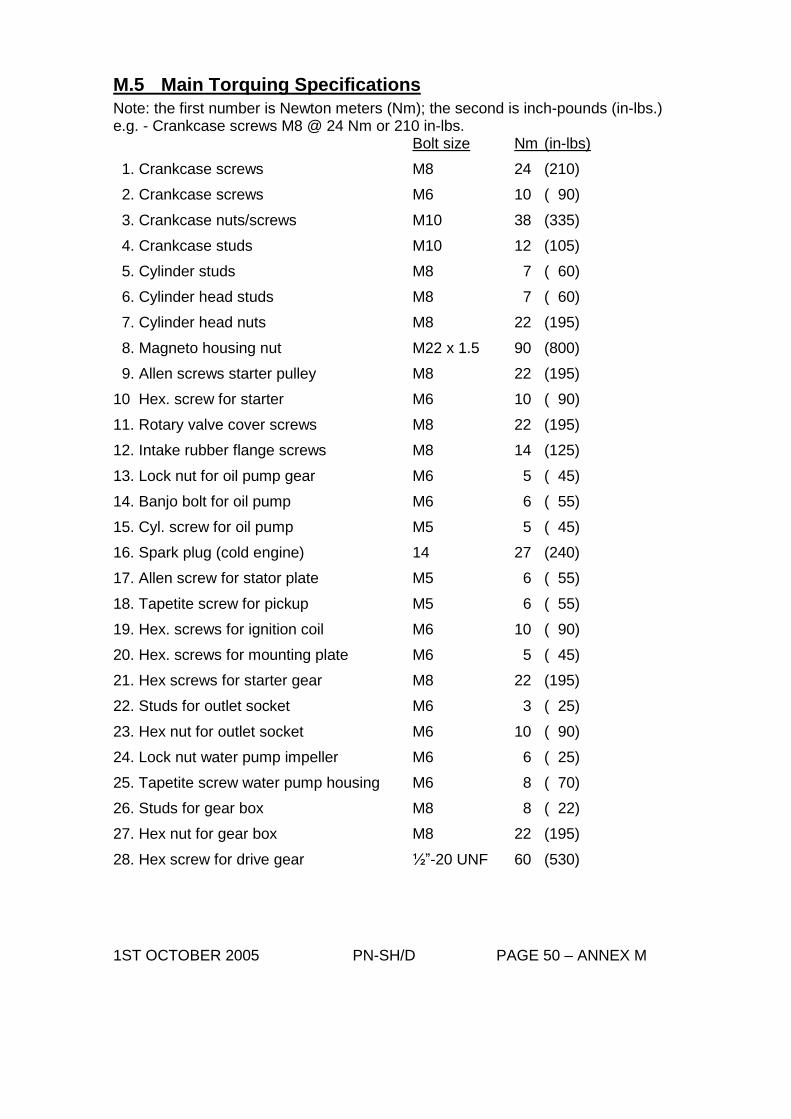
M.5 Main Torquing Specifications
Note: the first number is Newton meters (Nm); the second is inch-pounds (in-lbs.) e.g. - Crankcase screws M8 @ 24 Nm or 210 in-lbs. Bolt size Nm (in-lbs)
1. Crankcase screws M8 24 (210)
2. Crankcase screws M6 10 ( 90)
3. Crankcase nuts/screws M10 38 (335)
4. Crankcase studs M10 12 (105)
5. Cylinder studs M8 7 ( 60)
6. Cylinder head studs M8 7 ( 60)
7. Cylinder head nuts M8 22 (195)
8. Magneto housing nut M22 x 1.5 90 (800)
9. Allen screws starter pulley M8 22 (195)
10 Hex. screw for starter M6 10 ( 90)
11. Rotary valve cover screws M8 22 (195)
12. Intake rubber flange screws M8 14 (125)
13. Lock nut for oil pump gear M6 5 ( 45)
14. Banjo bolt for oil pump M6 6 ( 55)
15. Cyl. screw for oil pump M5 5 ( 45)
16. Spark plug (cold engine) 14 27 (240)
17. Allen screw for stator plate M5 6 ( 55)
18. Tapetite screw for pickup M5 6 ( 55)
19. Hex. screws for ignition coil M6 10 ( 90)
20. Hex. screws for mounting plate M6 5 ( 45)
21. Hex screws for starter gear M8 22 (195)
22. Studs for outlet socket M6 3 ( 25)
23. Hex nut for outlet socket M6 10 ( 90)
24. Lock nut water pump impeller M6 6 ( 25)
25. Tapetite screw water pump housing M6 8 ( 70)
26. Studs for gear box M8 8 ( 22)
27. Hex nut for gear box M8 22 (195)
28. Hex screw for drive gear ½”-20 UNF 60 (530)
1ST OCTOBER 2005 PN-SH/D PAGE 50 – ANNEX M
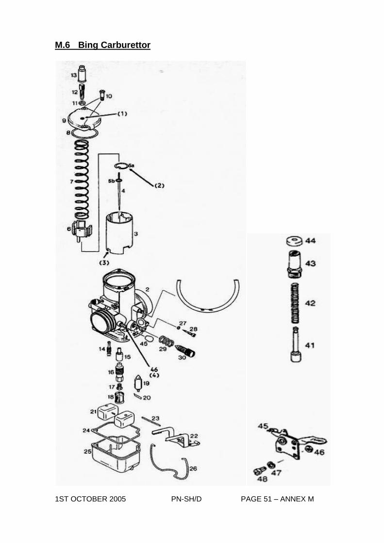
M.6 Bing Carburettor
1ST OCTOBER 2005 PN-SH/D PAGE 51 – ANNEX M
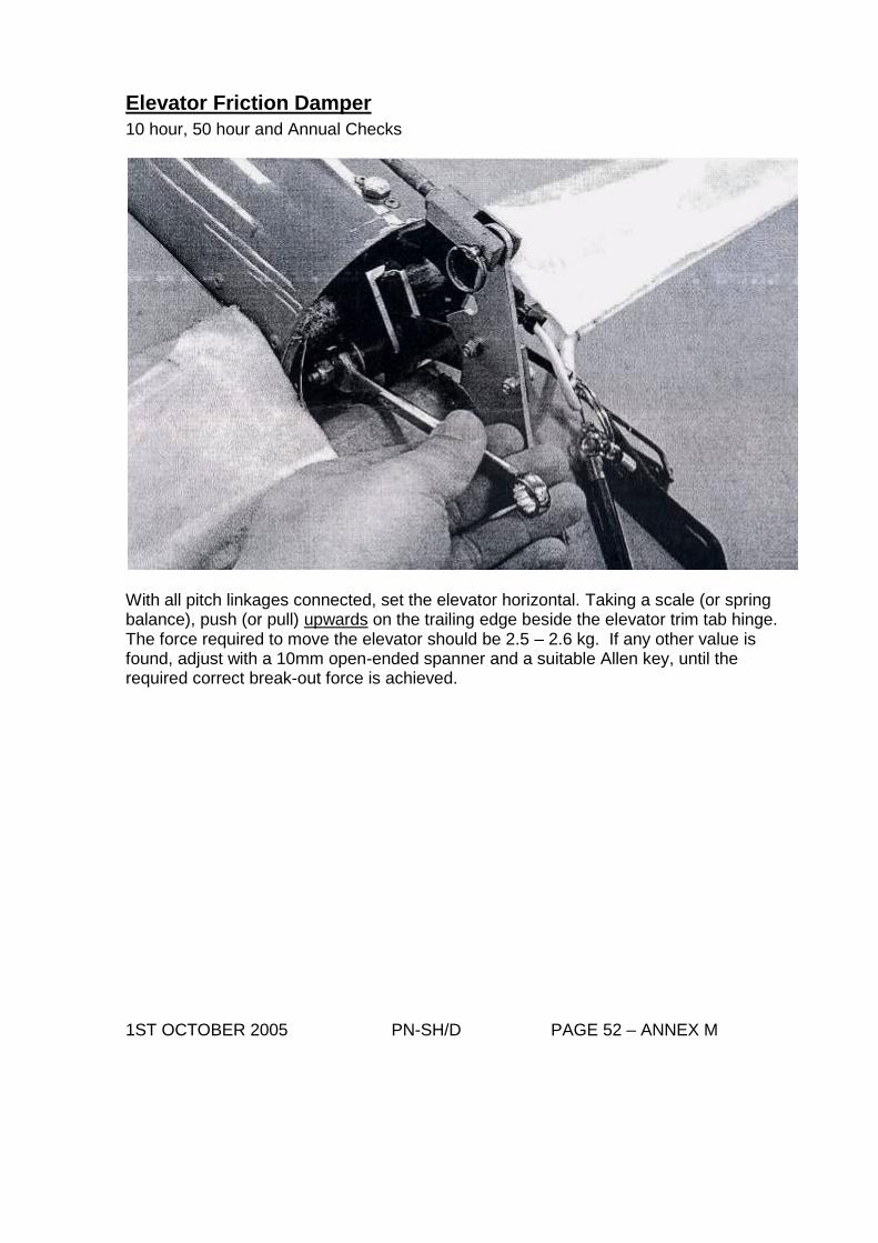
Elevator Friction Damper
10 hour, 50 hour and Annual Checks
With all pitch linkages connected, set the elevator horizontal. Taking a scale (or spring balance), push (or pull) upwards on the trailing edge beside the elevator trim tab hinge. The force required to move the elevator should be 2.5 – 2.6 kg. If any other value is found, adjust with a 10mm open-ended spanner and a suitable Allen key, until the required correct break-out force is achieved. 1ST OCTOBER 2005 PN-SH/D PAGE 52 – ANNEX M
Inspection
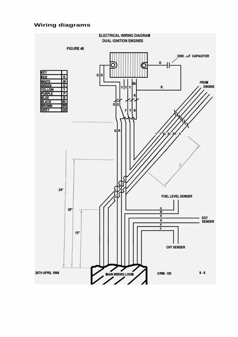
Wiring diagrams