Embed Size (px)
Citation preview
7/29/2019 CFL800E
http://slidepdf.com/reader/full/cfl800e 1/4
BIDDLE CFL800E
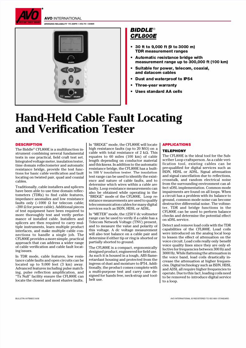
Hand-Held Cable Fault Locatingand Verification Tester DESCRIPTION
The Biddle ® CFL800E is a multifunction in-strument combining several fundamentaltests in one practical, field craft test set.Integrated voltage meter, insulation tester,time domain reflectometer and automaticresistance bridge, provide the test func-tions for basic cable verification and faultlocating on twisted pair, quad and coaxial
cables.Traditionally, cable installers and splicershave been able to use time domain reflec-tometers (TDRs) to find cable features,impedance anomalies and low resistancefaults only (<1000 Ω for telecom cable;<200 Ω for power cable). Additional piecesof test equipment have been required tomore thoroughly test and verify perfor-mance of installed cable. Installers andsplicers are then required to carry mul-tiple instruments, learn multiple productinterfaces, and make multiple cable con-nections to handle a single job. TheCFL800E provides a more simple, practical
approach that can address a wider rangeof cable verification and cable fault locat-ing issues.
In TDR mode, cable features, low resis-tance cable faults and open circuits can belocated up to 9,000 feet (3 km) away.Advanced features including pulse match-ing, pulse reflection amplification, and“Tx Null” facility ensure the CFL800E canlocate the closest and most elusive faults.
In “BRDGE” mode, the CFL800E will locatehigh resistance faults (up to 20 M Ω ) on acable with total resistance of 2 k Ω. Thisequates to 60 miles (100 km) of cablelength depending on conductor materialand thickness. In addition to the automaticresistance bridge, the CFL800E has a built-in 100 V insulation tester. The insulationtest range can be used to identify the exist-ence and nature of cable faults, and todetermine which wires within a cable arefaulty. Loop resistance measurements canalso be obtained while operating in the“BRDGE” mode of the CFL800E. Loop re-sistance measurements are used to qualifytelecommunication cables for many digitalservices such as ISDN, HDSL or ADSL.
In “METER” mode, the ±250 V dc voltmeterrange can be used to verify if a cable has aTelecom Network Voltage (TNV) present,and to measure the value and polarity ofthis voltage. A dc voltage measurementwill also test balance on a cable pair anddetermine if either tip or ring is shorted orpartially shorted to ground.
The CFL800E is a compact, ergonomicallydesigned product, engineered for field use.As such it is housed in a tough, ABS flame-retardant housing and protected from theingress of dust and moisture to IP54. Addi-tionally, the product comes complete witha multi-purpose test and carry case de-signed for hands free, neck-strap and tool-belt use.
APPLICATIONS
TELEPHONY
The CFL800E is the ideal tool for the Sub-scriber Loop craftsperson. As a cable veri-fication tool, existing cables can bepre-qualified for digital services such asISDN, HDSL or ADSL. Signal attenuationand signal cancellation due to reflections,crosstalk, and random electrical noisefrom the surrounding environment can af-fect xDSL implementation. Common modeimpairments are found on all loops. Whena circuit has a problem with its balance toground, common mode noise can becomedestructive differential noise. The voltme-ter, TDR and bridge functions in theCFL800E can be used to perform balancechecks and determine the potential effecton xDSL service.
Detect and remove load coils with the TDR capabilities of the CFL800E. Load coilswere introduced on the analog local loopto lessen the effect of attenuation on thevoice circuit. Load coils really only benefitvoice quality lines since they are only ef-fective for frequencies between 300 Hz and3000 Hz. While flattening the attenuation inthe voice band, load coils drastically in-crease the attenuation at higher frequen-cies. Digital technology such as ISDN, HDSLand ADSL all require higher frequencies tooperate. Due to this fact, loading coils needto be removed to introduce digital serviceto a loop.
• 30 ft to 9,000 ft (9 to 3000 m)TDR measurement ranges
• Automatic resistance bridge withmeasurement range up to 300,000 ft (100 km)
• Suitable for power, telecom, coaxial,and datacom cables
• Dust and waterproof to IP54
• Three-year warranty
• Uses standard AA cells
AVO INTERNATIONAL
BRINGING RELIABILITY TO AMPS • VOLTS • OHMS
BULLETIN AVTB800E 8/00 AVO INTERNATIONAL IS REGISTERED TO ISO 9001 STANDARD
7/29/2019 CFL800E
http://slidepdf.com/reader/full/cfl800e 2/4
BIDDLE CFL800E
When cable failure impairs or interruptsservice, the CFL800E becomes the first lineof defense in uncovering and locating cablefaults. Fault locating capabilities integratedinto the CFL800E allow field personnel theability to identify:
• Splice problems such as wet splices orhigh resistance splices
• Presence of water in cables
• Opens or shorts in the tip, ring andsheath
OTHER APPLICATIONS
The integrated functions of the CFL800Emake it ideal for the demanding applica-tions encountered in CATV, LAN, and air-craft wire testing.
CATV
The features offered in the CFL800E pro-vide the ability to test cable integrity aswell as locate faults and illegal subscrib-ers. Specific cable conditions identified in-clude:
• Bends or crimps in the cable
• Cuts or shorts in the cable
• Taps and splits
• Connectors and splices• Water ingress
• Cable frays
LOCAL AREA NETWORKS ANDPREMISE WIRING SYSTEMS
When installing or designing LANs andpremise wiring systems, proper cablelength, cable balance and attenuationspecifications are critical for optimum per-formance. The CFL800E tests and mea-sures:
• Insulation resistance
• Loop resistance on twisted-pair cables
• Line balance
• Cable faults such as opens and shorts
• Defective connectors
• Kinks, bends or frays within a cable
AIRCRAFT WIRING
The CFL800E performs the necessary teststo ensure the integrity of control and com-munication cable in aircraft. The unit willdetermine:
• Location of cable breaks or shorts• Location of frays, kinks, or bends
• Insulation resistance of cables
FEATURES AND BENEFITS
Combined Resistance Bridge and TDR Fault Locator - Just One BoxConventional TDRs are only able to iden-tify and locate cable faults that are eitheropen or short circuits, or have a fault resis-tance below about 1000 Ω. Above this levelof fault resistance, TDR technology fails asno significant reflection of the transmittedpulse occurs at the point of fault. TheCFL800E contains additional AutomaticResistance Bridge circuitry that enablesthe product to accurately identify and lo-cate faults with a fault resistance as highas 20 M Ω.
Automatic Balance Resistance Bridge –Reduces Testing TimeConventional resistance bridge measuringinstruments require the manual balancingof a galvanometer circuit by the operator,a time consuming, difficult and thereforecostly process. The CFL800E contains ad-vance automatic balancing circuitry toeliminate the need for operator balancing,dramatically reducing testing time andeliminating operator error.
Multiple test functions - Determine how well a local loop can reject commonmode noise.Signal attenuation and signal cancellationdue to reflections, crosstalk, and randomelectrical noise from the surrounding envi-ronment can affect xDSL implementation.Common mode impairments are found onall loops. When a circuit has a problemwith its balance to ground, common modenoise can become destructive differentialnoise. The voltmeter, TDR and bridge func-tions in the CFL800E can be used to per-form balance checks and determine thepotential effect on xDSL service.
Built-in Insulation Tester – Determine if a fault exists and what typeNormally before the process of cable veri-fication can begin it is necessary for theindividual doing the testing to identifywhether there is a problem on the cableand to identify the nature and type of thefault. In other words what type of fault isit? Is it between conductors or is it anearth fault? To determine this a separateinsulation resistance tester is generally
used. With the CFL800E the insulationtester is built in, and thus eliminates theneed for additional test instruments to beprocured and carried.
Built-in DC Voltmeter – Determine if theLine is Wet or DryGenerally, to ensure operator and networksafety prior to commencement of any typeof fault diagnosis or location process, it isimportant to ensure that the line is de-energized and disconnected from the “net-work.” Also, when working on telecomsystems the individual doing the fault lo-cating may wish to measure the TelecomNetwork Voltage (TNV). For both of theseapplications the CFL800E has a built in DCvoltmeter range, again eliminating theneed for additional test instruments to beprocured and carried.
“TX Null” - Transmit Pulse Nulling -Eliminates the “Dead Zone”
Adjustment of the “TX Null” balance con-trol in TDR mode ensures the swampingassociated with the output pulse of theCFL800E is eliminated from the displayedwaveform. Elimination of the transmittedpulse allows the reflection caused by afault on a cable close to the point of test tobe displayed. On TDRs without this facil-ity, the transmit pulse obscures near endreflections making close in faults impos-sible to see.
Auto Ranging around the Cursor PositionThe CFL800E automatically adjusts therange around the cursor position to thelowest range for that position and selectsthe gain for that range (gain is then useradjustable). This feature ensures that theoperator is viewing the fault condition onthe lowest possible range (providing themost accurate fault location information).
Reflection Amplitude Gain Control -Location and IdentificationIn TDR mode the pulse detection circuitrygain is automatically set for the measure-ment range selected by the operator. In-creasing amplitude enables weaker signalsand distant faults to be identified. Decreas-ing the amplitude gain setting reducesnoise and can assist in fault discrimina-tion. The CFL800E has four selectable gainsettings.
7/29/2019 CFL800E
http://slidepdf.com/reader/full/cfl800e 3/4
BIDDLE CFL800E
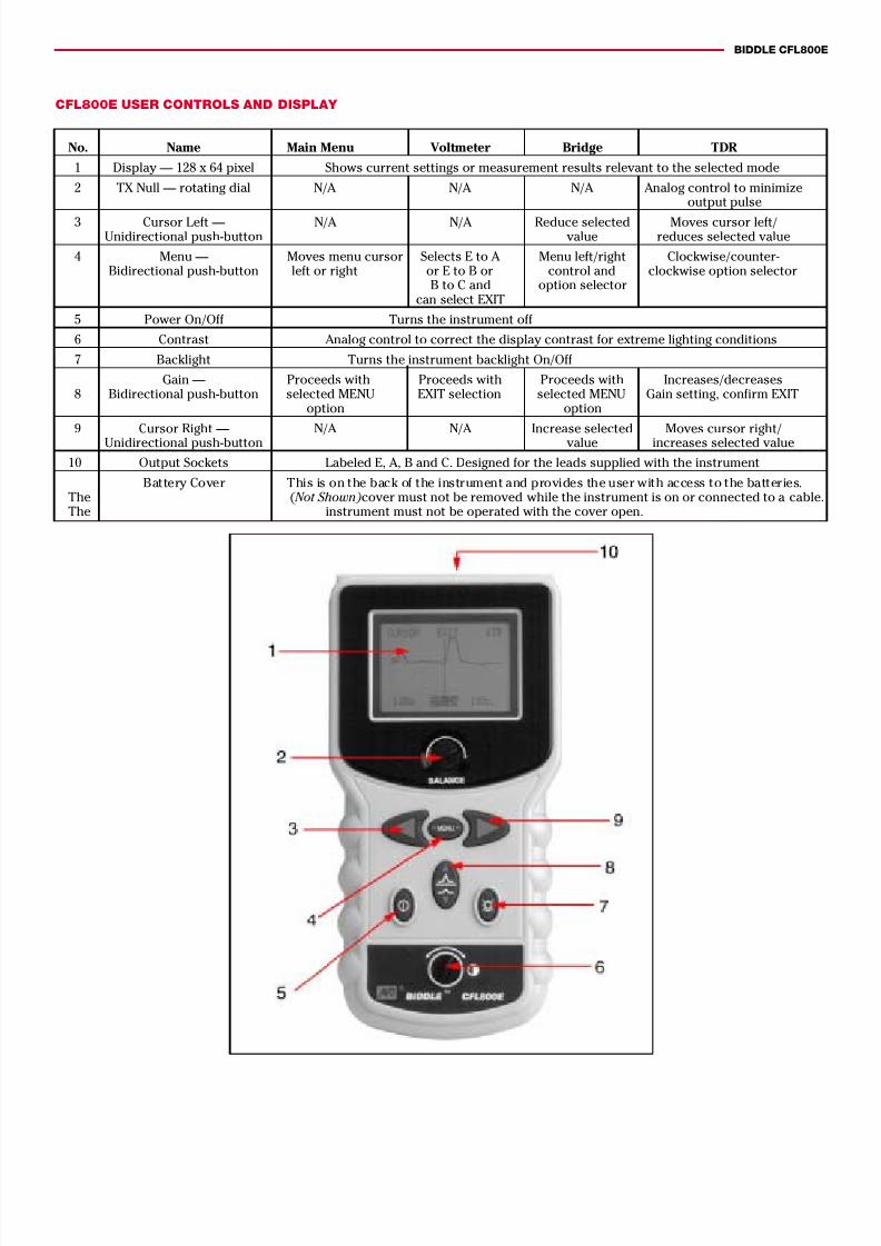
CFL800E USER CONTROLS AND DISPLAY
No. Name Main Menu Voltmeter Bridge TDR
1 Display — 128 x 64 pixel Shows current settings or measurement results relevant to the selected mode
2 TX Null — rotating dial N/A N/A N/A Analog control to minimizeoutput pulse
3 Cursor Left — N/A N/A Reduce selected Moves cursor left/Unidirectional push-button value reduces selected value
4 Menu — Moves menu cursor Selects E to A Menu left/right Clockwise/counter-Bidirectional push-button left or right or E to B or control and clockwise option selector
B to C and option selectorcan select EXIT
5 Power On/Off Turns the instrument off
6 Contrast Analog control to correct the display contrast for extreme lighting conditions
7 Backlight Turns the instrument backlight On/Off
Gain — Proceeds with Proceeds with Proceeds with Increases/decreases8 Bidirectional push-button selected MENU EXIT selection selected MENU Gain setting, confirm EXIT
option option
9 Cursor Right — N/A N/A Increase selected Moves cursor right/Unidirectional push-button value increases selected value
10 Output Sockets Labeled E, A, B and C. Designed for the leads supplied with the instrument
Battery Cover This is on the back of the instrument and provides the user with access to the batteries.The ( Not Shown) cover must not be removed while the instrument is on or connected to a cable.The instrument must not be operated with the cover open.
7/29/2019 CFL800E
http://slidepdf.com/reader/full/cfl800e 4/4
UNITED STATES CANADA
PO Box 9007 4651 S. Westmoreland Road 110 Milner Avenue, Unit 1Valley Forge, PA 19485-1007 Dallas, TX 75237-1017 Scarborough, ONT M1S 3R2Phone: (610) 676-8500 Phone: (214) 333-3201 Phone: (416) 298-6770Fax: (610) 676-8610 Fax: (214) 333-3533 Fax: (416) 298-0848
© 2000 AVO INTERNATIONAL PRINTED IN USAMIL/7.5M/900 BULLETIN-1 CFL800E TDR
SPECIFICATIONS
Except where otherwise stated, this speci-fication applies at an ambient temperatureof -4o F (20 o C).
TDR
Ranges30 ft, 90 ft, 300 ft, 900 ft, 3000 ft, 9,000 ft(10 m, 30 m, 100 m, 300 m, 1 km, 3 km)Resolution1% of range
Accuracy±1% of range ±pixel at 0.67 VF
Voltage Measuring Range+/-250VDC +/-1% +/- 1digit
GainSet for each range with four user selectablesteps
Velocity Factor Variable from 0.30 to 0.99 in steps of 0.01
Output pulse5 V peak to peak into open circuit
Output Impedance100 Ω
Balance Adjustment (TX Null)0 to 120 Ω
Update RateOnce per second for five minutes after lastkey pressed
BRIDGE
Loop and Fault Resistance Ranges0 to 190 Ω in steps of 0.1 Ω190 Ω to 2000 Ω in steps of 1 Ω
Accuracy of Fault Reading±0.2% ±1 digit from 0 Ω to 1 M Ω±0.2% ±3 digits from 1 M Ω to 5 M Ω±0.2% ±6 digits from 5 M Ω to 10 M Ω
Loop Reading±0.2% of reading ±1 digit on Ω
Voltage to Line100 V dc nominal
Current to Line100 µA dc nominal
Insulation Range0 to 19 M Ω in steps of 0.01 M Ω19 MΩ to 200 M Ω in steps of 0.1 M Ω
Insulation Accuracy±0.2% of reading ±1 digit
GENERAL
Input Protection300 Vdc or 300 Vac < 60 Hz
Power DownAutomatic after five minutes inactivity
BacklightOne minute when activated
Batteries
6 x LR6 (AA) nominal voltage 9 Vdc (alkali)7.2 V (NiCd)
Battery ConsumptionTDR Mode: 100 mA nominal, 140 mA with
backlight
Bridge Mode: 50 mA nominal, 90 mA withbacklight
Hours: 20/30 hours, depending on back-light use
SafetyMeets BS EN 61010-1: 1993 (includingamendment 2: 1995-06), andIEC 60950 3 rd Edition: 1999-04 and rated foruse on TNV-3 circuits.
If it is to be used in situations where hazard- ous live voltages may be encountered, anadditional blocking filter must be used.
EMCComplies with electromagnetic compatibil-ity specification (light industrial)BS/EN50081-1-1992 BS/EN50082-1-1992
MECHANICAL
Case Dimensions9.05 H x 4.5 W x 1.88 D in.(230 H x 115 W x 48 D mm)Instrument Weight1.32 lb (0.6 kg)
MaterialABS
ConnectorsFour x 4 mm-safety terminals (E, A, B, and C)
Lead6.5 ft (1.95 m)
Display128 x 64 pixel graphic LCD
ENVIRONMENTAL
Operationing Temperature5o F to 122 o F (-15 o C to +50 o C)
Storage Temperature-4o F to +158 o F (-20 o C to +70 o C)
ORDERING INFORMATION
Item Cat. No.
BIDDLE® CFL800E Hand-Held Cable Fault Locatingand Verification Tester.................................................. 655800E
Included Accessories:TDR bed of nails alligator test lead set ............................EV6231-653Bridge bed of nails alligator test lead set ........................EV6220-708
Item Cat. No.
Test and carry pouch ........................................................ EV6420-128User guide ........................................................................... EV6172-512
Optional Accessories:Mains blocking filter ...........................................................EV6220-669
BIDDLE CFL800E


