Embed Size (px)
Citation preview
CFD SIMULATION OF PARTICLE MIXING IN A FLUIDIZED BED
KONG DEYI
A project report submitted in partial fulfillment of the requirements
For the award of the degree of
Bachelor of Mechanical Engineering with Automotive Engineering
Faculty of Mechanical Engineering
UNIVERSITY MALAYSIA PAHANG
JUNE 2013

vi
ABSTRACT
This project is to do the research of CFD simulation of particle mixing in a fluidized
bed. Nowadays, fluidized bed is widely used in different kinds of industry, such as
power plant, petroleum industry and food processing industry. The objectives of this
project are to study the mixing and segregation phenomena in a fluidized bed and to
design distributors with low pressure drop operation. Fluidized beds suspend solid fuels
on upward-blowing jets of air during the combustion process. The main characteristics
of fluidized bed are pressure drop, fluid velocities, bubble size and bed height.
Computational fluid dynamics (CFD) simulation is the method to study this project.
Firstly, Ergun 6.2 software is used to study particle mixing and segregation phenomena.
Secondly, 3D geometry of fluidized bed is drawn by using Solidworks 2012. Flow
simulation program is used to study pressure drop in the fluidized bed 3D drawing.
Minimum fluidized velocity and operation point is found by using Ergun 6.2 software.
Pressure drop is found by using Flow Simulation program. Compare with other
researcher’s results these simulation results are accepted.

vii
ABSTRAK
Projek ini adalah untuk melakukan penyelidikan CFD simulasi zarah mencampurkan
dalam relau fluidized. Kini, relau fluidized digunakan secara meluas dalam pelbagai
industri, seperti loji kuasa, industri petroleum dan industri pemprosesan makanan.
Objektif projek ini adalah untuk mengkaji pengasingan pergaulan dan fenomena dalam
relau fluidized dan merekabentuk pengedar dengan operasi kejatuhan tekanan yang
rendah. Relau fluidized menggantung bahan api pepejal di atas-bertiup jet udara semasa
proses pembakaran. Ciri-ciri utama relau fluidized adalah kejatuhan tekanan, halaju
cecair, saiz gelembung dan ketinggian katil. Dinamik bendalir pengiraan (CFD)
simulasi adalah kaedah untuk mengkaji projek ini. Pertama, Ergun 6.2 perisian
digunakan untuk mengkaji zarah pergaulan dan fenomena pengasingan. Kedua,
geometri 3D relau fluidized diambil dengan menggunakan Solidworks 2012. Program
simulasi aliran digunakan untuk mengkaji kejatuhan tekanan di dalam relau lukisan 3D
fluidized. Halaju dibendalirkan minimum dan titik operasi didapati dengan
menggunakan Ergun 6.2 perisian. Kejatuhan tekanan yang didapati dengan
menggunakan program Simulasi Aliran. Bandingkan dengan hasil penyelidik lain
keputusan ini simulasi diterima.

viii
TABLE OF CONTENTS
Page
EXAMINER’S DECLARATION i
SUPERVISOR’S DECLARATION ii
STUDENT’S DECLARATION iii
ACKNOWLEDGEMENTS v
ABSTRACT vi
ABSTRAK vii
TABLE OF CONTENTS viii
LIST OF TABLES xi
LIST OF FIGURES xii
LIST OF SYMBOLS xiv
CHAPTER 1 INTRODUCTION
1.1 Background Studies 1
1.2 Problem Statement 2
1.3 Objectives 3
1.4 Scopes 3
CHAPTER 2 LITERATURE REVIEW
2.1 Basic Fluidized Bed System 4
2.2 Distributor
2.2.1 Function of Distributor
4
4
2.3 The Main Characteristics of Fluidized Bed 5
2.4 Pressure Drop 5
2.5 Fluid Velocities 12
1 × ENTER (1.5 line spacing)

ix
2.6 Particle Mixing and Segregation Phenomena 12
2.7 Bubbling 13
CHAPTER 3 METHODOLOGY
3.1 Study Internal Air Flow 15
3.2 CFD Simulation Study 15
3.3 Ergun 6.2
3.3.1 Ergun 6.2 simulation
15
16
3.4 Solidworks 2012 Flow Simulation
3.4.1 Solidworks model
3.4.2 Solidworks flow simulations
16
16
18
CHAPTER 4 RESULT AND DISCUSSION
4.1 Synopsis 31
4.2 Particle Mixing Simulation
4.2.1.1 Particle 1 simulation
4.2.1.2 Particle 1 bubbling simulation
4.2.2.1 Particle 2 simulation
4.2.2.2 Particle 2 bubbling simulation
4.2.3.1 Particle 3 simulation
4.2.3.2 Particle 3 bubbling simulation
31
32
33
35
36
38
39
4.3 Pressure Drop Simulation 41
4.4 Compare with Other’s Result 43
CHAPTER 5 CONCLUSION
5.1 Conclusion 44
5.2 Recommendation 45
x
REFERENCES 46
APPENDICES
A Gantt chart 48
B List of flow simulation results 49
C Software specification 59
D Hardware specification 60
xi
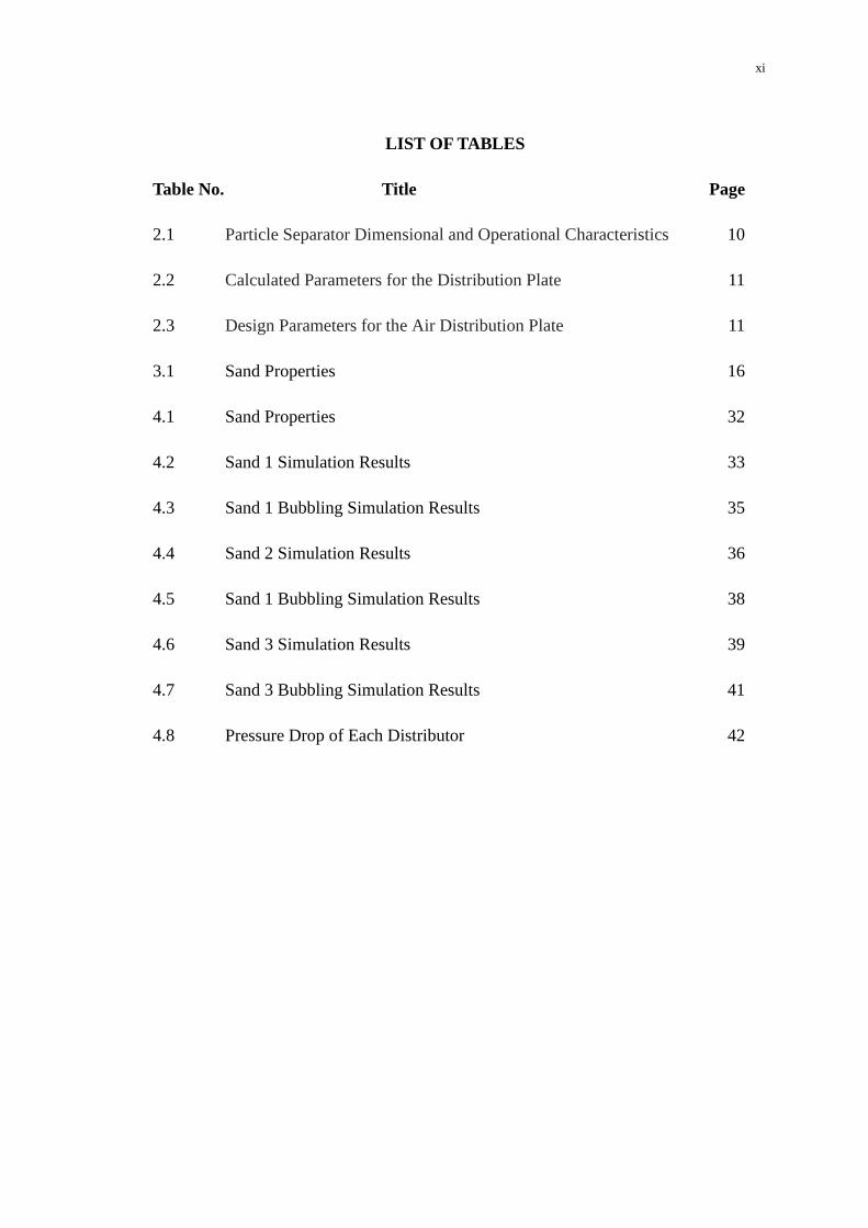
LIST OF TABLES
Table No. Title Page
2.1 Particle Separator Dimensional and Operational Characteristics 10
2.2 Calculated Parameters for the Distribution Plate 11
2.3 Design Parameters for the Air Distribution Plate 11
3.1 Sand Properties 16
4.1 Sand Properties 32
4.2 Sand 1 Simulation Results 33
4.3 Sand 1 Bubbling Simulation Results 35
4.4 Sand 2 Simulation Results 36
4.5 Sand 1 Bubbling Simulation Results 38
4.6 Sand 3 Simulation Results 39
4.7 Sand 3 Bubbling Simulation Results 41
4.8 Pressure Drop of Each Distributor 42

xii
LIST OF FIGURES
Figure No. Title Page
2.1 Pressure drop versus superficial gas velocity for initially
mixed/segregated mixtures
7
2.2 Comparison Plot of Experimental Bed Pressure Drop with CFD
Simulation using Gidaspow drag model
9
3.1 Design of Distributors 2mm and 3mm Linear Pattern 17
3.2 Design of Distributors 4mm and 5mm Linear Pattern 17
3.3 Dimension of the design 18
3.4
Solidworks tool bar
19
3.5 Create lids 19
3.6 Gravity and flow type setting 20
3.7 Select fluid 21
3.8 Result and geometry resolution setting 22
3.9 Subdomain setting 23
3.10 Boundary conditions setting 24
3.11 Run the calculation 25
3.12 Example of air flow result 25
3.13 Flow Chart of Flow Simulation 27
3.14 FYP 1 Flow Chart 28
3.15 Continue FYP 1 Flow Chart 29
3.16 FYP 2 Flow Chart 30

xiii
4.1 Particle 1, simulation 33
4.2 Sand 1, Bubbling Simulation of Operating Point 34
4.3 Sand 1, Bubbling Properties of Simulation 34
4.4 Sand 2, particle simulation 36
4.5 Sand 2, Bubbling Simulation of Operating Point 37
4.6 Sand 2, Bubbling Properties of Simulation 37
4.7 Sand 3, Particle Simulation 39
4.8 Sand 3 Bubbling Simulation of Operating Point 40
4.9 Sand 3 Bubbling Properties of Simulation 40
4.10 Variation of Distributors 42
4.11 Result From Other Researcher 43
xiv
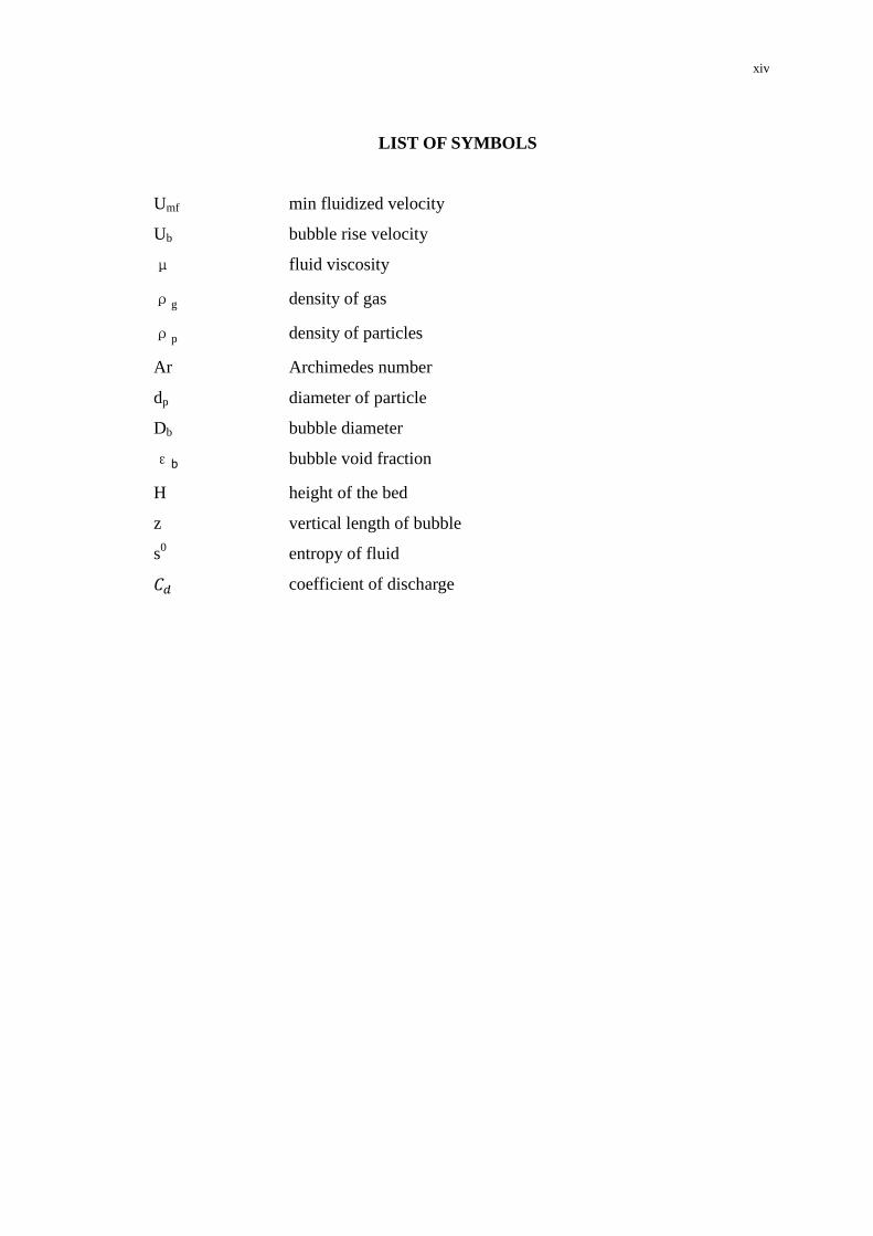
LIST OF SYMBOLS
Umf min fluidized velocity
Ub bubble rise velocity
μ fluid viscosity
ρg density of gas
ρp density of particles
Ar Archimedes number
dp diameter of particle
Db bubble diameter
εb bubble void fraction
H height of the bed
z vertical length of bubble
s0 entropy of fluid
coefficient of discharge

CHAPTER 1
INTRODUCTION
1.1 BACKGROUND STUDIES
Currently, environment pollution is one of the most serious issues in the world
such as ozone layer depletion, acid rains and greenhouse effect (Proimos, 2011). From
the study, industrial combustion plays the main role to contribute the polluted gases to
atmosphere.
Research suggested that fluidized bed is a good device to reduce the toxic gases
emission in industry. In general, fluidized bed is a coal burning furnace in which the air
is passed through the hot and turbulent bed of sand or ash. It behaves like a fluid, and
the coal will burned efficiently at lower temperatures to reduce nitrogen oxides
emission. If limestone is added to the bed along with the coal, the emission of sulfur
dioxide to the atmosphere can be further reduced significantly (Oxford World
Encyclopedia 1998).
Fluidized bed is applicable in different areas. Back to 1922, the first industrial
application of fluidization in the coal gasification reactor was made by Fritz Winkler. In
1940s, the fluidized solid process was successfully commercialized on a massive scale
in the petroleum industry to crack the heavy hydrocarbons to fuel oil and metallurgical
processing (roasting arsenopyrite). In the 1960s, VAW-Lippewerk in Lünen, Germany
implemented the first industrial bed for the combustion of coal and later for the
calcinations of aluminium hydroxide. However, the explosion of research, application

2
and commercialization of fluidized bed process in other industry only started since
1980s (Wang, 2003).
Nowadays, fluidized beds are also widely used in different kinds of industry.
First of all, fluidized bed is important equipment in power plant which is used for a coal
gasification process. In petroleum industry, fluidized bed is used for catalytic cracking
process which effects intimate contact between the catalyst and hot vapors in the
cracking of heavy hydrocarbons to fuel oil. In metallurgical industry, fluidized bed is
used for roasting arsenopyrite and calcinations of aluminum hydroxide. In food
processing industry, fluidized bed is used to accelerate freezing
(http://www.almoprocess.com/).
1.2 PROBLEM STATEMENT
The researches on fluidized bed have already been going for one hundred
years since the early of 20th
century (Wang, 2003). Until now, the fluidized bed is still
not used widely. Because the operation cost and installation cost are very high.
Eliminate the drawback CFD simulation of fluidized bed is required. CFD
simulation can increase the operation efficiency and reduce the installation and
operation cost. The simulation results of pressure drop can achieve low operation cost.
And particle mixing and segregation result can lead good combustion efficiency to
reduce pollution gases. This research is to prepare the high combustion efficiency, low
emission, and low operation cost fluidized bed for industrial use by using CFD
simulation.

3
1.3 OBJECTIVES
The objectives for this project are as follows
i. To study and predict the mixing and segregation phenomena in a fluidized bed
system.
ii. To design distributors with low pressure drop operation.
1.4 SCOPES
The scopes for this project are as follows
a. Study internal CFD simulation
b. Study Ergun fluidized bed model
c. 3D engineering drawing of fluidized bed and distributors model will be
used
d. Run Ergun simulation and air flow simulation
e. Data analysis and compare
f. Final report preparation

CHAPTER 2
LITERATURE REVIEW
2.1 BASIC FLUIDIZED BED SYSTEM
Fluidized beds suspend solid fuels on upward-blowing jets of air during the
combustion process. The result is a turbulent mixing of gas and solids. The tumbling
action, much like a bubbling fluid, provides more effective chemical reactions and heat
transfer (Grace John R., Leckner Bo, Zhu Jesse, Cheng Yi 2008).
2.2 DISTRIBUTOR
Distributor is a plate which is located at the bottom of the fluidized bed. The
fluid flows upward through the bed. It contains numerous holes, and makes the solid
particles to be suspended.
2.2.1 Function of Distributor
The major function of the distributor is to distribute the fluidizing gas across
the base of the bed so that it is maintained in the fluidized condition over the whole of
its cross-section. The distributor also plays a major part in determining the size of the
bubbles in the bed which are the major cause of particle circulation (Qureshi and Creasy
1978).

5
2.3 THE MAIN CHARACTERISTICS OF FLUIDIZED BED
The ideal fluidization bed showed similar to the nature of the liquid. The fluid
density is smaller than the average density of the bed may be suspended in the bed
surface; maintain the level of bed surface; bed obey hydrostatic relationship, i.e. height
difference L of the two cross section of the differential pressure.
△ p = ρgL (2.1)
Particles having with a liquid like fluidity can be ejected from the orifice of the wall.
The above properties make the phenomenon of the particulate material in the
fluidized bed can be like a fluid continuous feeding and discharging the bed has a
unique advantage to a wide range of applications, and due to the uniform particle
sufficiently mixed bed temperature, concentration.
In the two-phase movement of fluid and particles within the bed, due to the
differential flow rate, fluid density of the particles, the particle size and the different
sizes of the bed, can exhibit different fluidized state, but mainly divided into the
fluidization state and aggregative fluidized state (Grace John R., Leckner Bo, Zhu Jesse,
Cheng Yi 2008).
2.4 PRESSURE DROP
The air through the distributor pressure should be different. It is relatively
undisturbed by the bed pressure fluctuations above it.
Treated as a combination of a sudden contraction followed by a sudden
enlargement, a simple drilled orifice in a distribution plate would be expected to have an
overall pressure drop given by
(2.2)
In consistent units, or
(2.3)
6
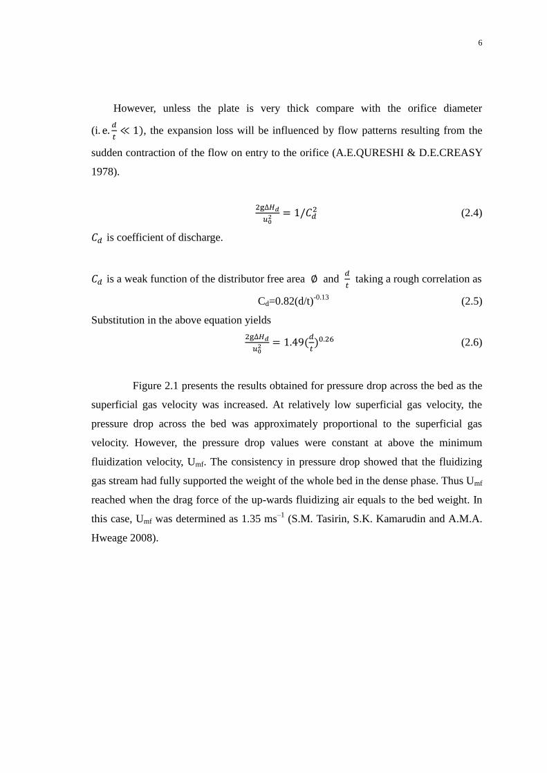
However, unless the plate is very thick compare with the orifice diameter
(
, the expansion loss will be influenced by flow patterns resulting from the
sudden contraction of the flow on entry to the orifice (A.E.QURESHI & D.E.CREASY
1978).
(2.4)
is coefficient of discharge.
is a weak function of the distributor free area and
taking a rough correlation as
Cd=0.82(d/t)-0.13
(2.5)
Substitution in the above equation yields
(2.6)
Figure 2.1 presents the results obtained for pressure drop across the bed as the
superficial gas velocity was increased. At relatively low superficial gas velocity, the
pressure drop across the bed was approximately proportional to the superficial gas
velocity. However, the pressure drop values were constant at above the minimum
fluidization velocity, Umf. The consistency in pressure drop showed that the fluidizing
gas stream had fully supported the weight of the whole bed in the dense phase. Thus Umf
reached when the drag force of the up-wards fluidizing air equals to the bed weight. In
this case, Umf was determined as 1.35 ms–1
(S.M. Tasirin, S.K. Kamarudin and A.M.A.
Hweage 2008).

7
Superficial Gas Velocity, U(m/s)
Figure 2.1: Pressure drop versus superficial gas velocity (at increasing gas flow rate)
for initially mixed/segregated mixtures (S.M. Tasirin, S.K. Kamarudin and A.M.A.
Hweage 2008).
Many researchers now use the kinetic theory of granular materials as part of
their efforts in simulating multiphase systems. It is used in both the dilute-phase
modeling of circulating fluidized beds and the dense phase modeling of bubbling
fluidized beds. The granular kinetic theory is also found in multiphase modeling within
the commercial simulation software FLUENT, with Benyahia using an early version of
FLUENT in their simulations of dilute-phase riser flow. Arastoopour were the first to
consider polydisperse systems and successfully computed pressure drop effects in dilute
riser flow (Scott Cooper, Charles J. Coronella 2004).
At the simulation study, a 2D CFD model was used to describe the gas–solid
two-phase flow in fluidized bed polymerization reactors. The effects of some important
input parameters on the flow field were investigated. The model was validated by
comparing the pressure drop and the minimum fluidization velocity data with those
calculated according to the classical equation. The effects of distributor shape, solid
particle size, operation gas velocity and the feed manner on the flow behavior in the
reactor. The results show that the final fluidizations are almost the same at the plane and

8
triangle distributors. In addition, with the increase of the solid particle diameter, the
bubble number decreases and the bubble size increases, resulting in a small bed
expansion ratio. Both the bubble number and the bed expansion ratio increase with the
increase of the gas inlet velocity. There exists a tempestuous wiggle from side to side in
the bed at the continuous feed manner, which cannot be found at the batch feed manner.
Further studies on the CFD model for the gas–solid two-phase flow in FBR are in
progress in our group (Xi-Zhong Chen, De-Pan Shi, Xi Gao, Zheng-Hong Luo 2010).
Relate to this project the straight cylindrical or columnar fluidized beds are the
majority of the gas-solid fluidization studies. There is another kind of fluidized beds,
which have inclined walls. These are called tapered fluidized beds.
Tapered fluidized beds can be run swimmingly without any unstableness,
which can be run with less pressure fluctuations. Tapered fluidized beds are very useful
for fluidization of materials with a wide particle size distribution, as well as for
exothermic reactions and also for extensive particle mixing.
In the present work, an Eulerian–Eulerian multi-fluid model, which considers
the conservation of mass and momentum for the solid and gas phases, has been adopted.
The kinetic theory of granular flow, which considers the conservation of solid
fluctuation energy, has been used for closure.

9
Superficial Gas Velocity, U(m/s)
Figure 2.2: Comparison Plot of Experimental Bed Pressure Drop with CFD Simulation
using Gidaspow drag model (particle = glass bead, diameter = 2 mm,
Initial static bed height = 6.5 cm) (D.C. Sau & K.C. Biswal 2010).
The floating gas-solids fluidized bed has been applied as a binary fluidized bed
and it was shown that its appearance may vary from well-mixed to completely separate.
Visual observation showed that intermediate mixing regimes could exist, as well as the
extreme situations of complete separation and good mixing of particles. These
observations were supported by the interpretation of measured pressure-drop profiles
due to the presence of particles: different degrees of mixing were reported, varying from
completely separated to intermediately and well-mixed (G. Kwant W. Prins W.P.M. van
Swaaij 1994).
Another type of distributor is tuyer type air distributor. A Tuyer type air
distributor plate was selected, consisting of a plate with vertical nozzles with lateral
perforations through which passes the air that is distributed uniformly into the reactor.
This alternative was selected due to its convenience for use with high temperatures and
its advantage of reducing the backflow of bed material toward the plenum. Table 2.1

10
shows the necessary parameters for the air distribution plate design considered for the
most homogenous material of the bed and sand.
Table 2.1: Particle separator dimensional and operational characteristics
Parameter Value
Cyclone diameter (mm) 190.5
Cyclone gas exit diameter (mm) 95.25
Cyclone body cylindrical height (mm) 285.75
Cyclone total height (mm) 762
Cyclone solids exit diameter (mm) 71.4
Separation efficiency (%) 99.7
Pressure drop (kPa) 0.46
Source: Ramirez, Martinez and Petro (2007)
From the mass flow of the product gas in the gasification process (mass
balance), and its density, the gas volumetric flow at the cyclone inlet for the operating
conditions of the gasifier was calculated (approximately 750 ºC and 101,325 kPa). Table
7 shows the dimensions of the designed cyclone, along with its efficiency and pressure
drop.
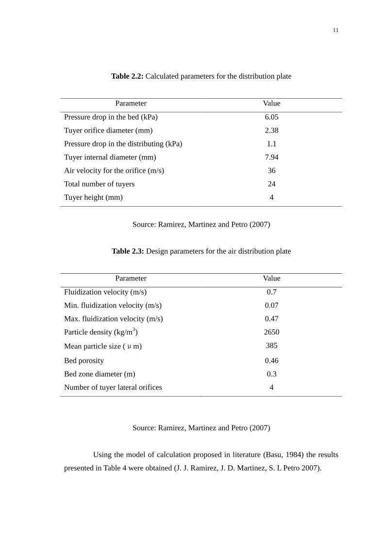
11
Table 2.2: Calculated parameters for the distribution plate
Parameter Value
Pressure drop in the bed (kPa) 6.05
Tuyer orifice diameter (mm) 2.38
Pressure drop in the distributing (kPa) 1.1
Tuyer internal diameter (mm) 7.94
Air velocity for the orifice (m/s) 36
Total number of tuyers 24
Tuyer height (mm) 4
Source: Ramirez, Martinez and Petro (2007)
Table 2.3: Design parameters for the air distribution plate
Parameter Value
Fluidization velocity (m/s) 0.7
Min. fluidization velocity (m/s) 0.07
Max. fluidization velocity (m/s) 0.47
Particle density (kg/m3) 2650
Mean particle size (μm) 385
Bed porosity 0.46
Bed zone diameter (m) 0.3
Number of tuyer lateral orifices 4
Source: Ramirez, Martinez and Petro (2007)
Using the model of calculation proposed in literature (Basu, 1984) the results
presented in Table 4 were obtained (J. J. Ramirez, J. D. Martinez, S. L Petro 2007).

12
2.5 FLUID VELOCITIES
There are many kinds of velocity have been studied in journals. First is
fluidized velocity of the particles. Second is bubble rise velocity. Third is fluid flow
velocity. Forth is superficial gas velocity. The objects of the velocity which have been
studied are particles, fluid and bubbles.
From one journal, they study proved that, Lacey index, M capable to
determine the performance of particle mixing and recommend the bubbling fluidized as
a good alternative for solid mixing. Finally the optimum parameters for solid mixing in
this study was determined the bed depth of 17 cm with the gas velocity 1.38 Umf that
give highest Lacey mixing index. This study also proved that the superficial velocity of
air higher that Umf, capable to reduce the effect of bed height to the mixing process
(S.M. Tasirin, S.K. Kamarudin and A.M.A. Hweage 2008).
2.6 PARTICLES MIXING AND SEGREGATION PHENOMENA
Various models have been proposed to describe structural phenomena such as
segregation, mixing, and layer compositions in binary particle systems (Di Felice, 1993;
Gibilaro et al., 1985; Juma and Richardson, 1979, 1983; Dutta et al., 1988; Kennedy
and Bretton, 1966; Asif and Petersen, 1993). Experimental and empirical results for the
pressure and concentration profiles that exist in binary systems have been used to make
predictions of the solids concentration in segregated systems. Kennedy and Bretton
(1966) and A-Dibouni and Garside (1979) predicted binary segregation using a model
that matched the diffusive and convective fluxes of each component. Other phenomena
such as layer inversion have also been studied (Moritomi et al., 1982; Van Duijn and
Rietema, 1982; Epstein and LeClair, 1985; Matsuura and Akehata, 1985; Gibilaro et al.,
1986; Syamlal and O’Brien, 1988; Di Felice et al., 1988; Jean and Fan, 1986;
Patwardhan and Tien, 1985). Correspondence concerning this article should be
addressed to M. A. Burnr. Current address of K. D. Seibert: Merck and Co., Inc., P.O.
Box 2000, RY50D-207, Rahway, NJ 07065. An example of a structural phenomenon
seen in a mixed particle liquid-fluidized bed is classification. Classification is the result

13
of the stable fluidization of particles with nonuniform particle diameters and/or densities.
The changing hydrodynamic forces on the particles cause them to segregate or “classify”
with larger particles gravitating toward the bottom of the bed and smaller particles
toward the top. Classified beds are currently used industrially in the isolation of
adsorbing solutes (Gailliot, 1990; Draeger and Chase, 1990; Chase and Draeger, 1992;
Chase, 1994; Batt, 1995). Knowledge of the fluidization characteristics, the operating
parameters, and the physical properties of the particles/ bed is important in this type of
application in order to maintain the stable classified structure.
2.7 BUBBLING
A multi-fluid computational fluid dynamics (CFD) model based on kinetic
theory of granular flow and Eulerian–Eulerian approach for binary mixture of particles
was presented. The multi-fluid model with gas phase and two particle phases of either
different particle sizes or densities is used to simulate flows in bubbling gas–solid
fluidized beds. The flow behavior of particle mixing or separation in bubbling fluidized
beds was numerically predicted. Details of particle collision information were obtained
through tracing particle motions based on Eulerian–Lagrangian approach coupled with
the discrete hard-sphere model. The distributions of volume fraction, velocity and
granular temperature of particles of two different sizes or densities were obtained. The
discrete hard-sphere modeling results quantified the granular temperatures, particle
fluctuating velocities, particle phase stresses, as well as the particle shear viscosities.
The simulations using both the multi-fluid model and the discrete hard-sphere model
clearly indicate particle separation phenomenon in the fluidized beds, where relatively
larger or heavier particles are observed near the bed bottom than at the bed top region
while relatively smaller or lighter particles were found at bed top than at the bed bottom.
Better particle mixing can be obtained by increasing the fluidizing velocity (Lu Huilin,
ZhaoYunhua, Jianmin Ding, Dimitri Gidaspow, LiWei 2006).
Sun and Battaglia 2006 performed simulations with and without particle
rotation to study segregation phenomena in a bi-dispersed bubbling gas-fluidized bed
using a multi-fluid Eulerian model. They claimed that with particle rotation in the
kinetic theory model and slightly friction considered the multi-fluid model better

14
captures the bubble dynamics and time-averaged bed behavior.
The distribution of particle mass fraction along the bed height for binary
mixture with same particle densities but diameters has been experimentally studied in a
bubbling fluidized bed (Huilin 2003).
These are the equations of calculate the mean bubble volume fraction.
(2.7)
(2.8)
(2.9)
+U- (2.10)
(2.11)
) (2.12)