Embed Size (px)
Citation preview
BIOS BIOENERGIESYSTEME GmbH Inffeldgasse 21b, A-8010 Graz, Austria
TEL.: +43 (316) 481300; FAX: +43 (316) 4813004 E-MAIL: [email protected]
HOMEPAGE: http://www.bios-bioenergy.at
SU
ST A I N A B
LE
EC O N O M Y
P Ca
KM g
E N E R G Y B I O M A S S
A S H
Claudia Benesch, Robert Scharler, Ingwald Obernberger
CFD simulation of NOx formation in fixed-bed biomass combustion plants

BIOENERGIESYSTEME GmbH Inffeldgasse 21b, A-8010 Graz
SU
ST A I N A B
LE
EC O N O M Y
P Ca
KM g
E N E R G Y B I O M A S S
A S H
2
Contents
Scope of work
Modelling
Empirical fixed bed modelling and release of NOx pre-cursors
Modelling of turbulent reactive flow – basic combustion modelling
CFD NOx postprocessing
Case study – methodology and discussion of results
Summary and conclusions
BIOENERGIESYSTEME GmbH Inffeldgasse 21b, A-8010 Graz
SU
ST A I N A B
LE
EC O N O M Y
P Ca
KM g
E N E R G Y B I O M A S S
A S H
3
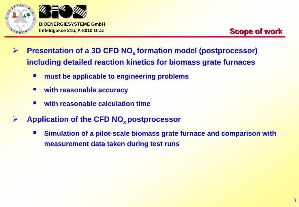
Scope of work
Presentation of a 3D CFD NOx formation model (postprocessor) including detailed reaction kinetics for biomass grate furnaces
must be applicable to engineering problems
with reasonable accuracy
with reasonable calculation time
Application of the CFD NOx postprocessor
Simulation of a pilot-scale biomass grate furnace and comparison with measurement data taken during test runs

BIOENERGIESYSTEME GmbH Inffeldgasse 21b, A-8010 Graz
SU
ST A I N A B
LE
EC O N O M Y
P Ca
KM g
E N E R G Y B I O M A S S
A S H
4
Empirical fixed bed model – basic version
Definition of profiles for the distribution of primary air and recirculated flue gas as well as
drying and thermal decomposition of the solid biomass (C, H, O) along the grate on the
basis of test runs
Definition of conversion parameters for CH4, H2, CO, CO2, H2O, and O2 in the flue gas released based on literature data and lab-scale experiments
Stepwise balancing of mass, species and energy
Calculated profiles of temperature, mass flux and species concentration in the flue gas along the grate for grass pellets
tem
pera
ture
[°C
]
mas
s flu
x [k
g/m
²s]
temperature mass flux
length on grate [m] length on grate [m]
conc
entr
atio
n [w
t% w
.b.]

BIOENERGIESYSTEME GmbH Inffeldgasse 21b, A-8010 Graz
SU
ST A I N A B
LE
EC O N O M Y
P Ca
KM g
E N E R G Y B I O M A S S
A S H
5
Extension of the fixed bed model – release of N species
The empirical fuel bed combustion model was extended in order to describe the release of N species (NO and NH3 as well as HCN) which are relevant for the formation of fuel NOx in biomass grate furnaces
Conversion parameters (as a linear function of local λ) were defined for the investigated fuels based on lab-scale pot furnace (batch) reactor experiments; NH3 showed to be the pre-dominant NOx precursor, HCN and NO were found in lower concentrations
Example: calculated profiles of NH3, HCN and NO concentration in the flue gas along the grate (left - fuel: corncobs; right - fuel: grass pellets)
length on grate [m]
conc
entr
atio
n [w
t% w
. b.]
length on grate [m]
conc
entr
atio
n [w
t% w
. b.]
BRUNNER Thomas, BIEDERMANN Friedrich, KANZIAN Werner, EVIC Nikola, OBERNBERGER Ingwald. 2012: Advanced biomass fuel characterisation based on tests with a specially designed lab-scale reactor. In: Proc. of the Int. Conference “Impacts of Fuel Quality on Power Production and Environment”, September 2012, Puchberg, Austria, ISBN 978-3-9502992-8-1

BIOENERGIESYSTEME GmbH Inffeldgasse 21b, A-8010 Graz
SU
ST A I N A B
LE
EC O N O M Y
P Ca
KM g
E N E R G Y B I O M A S S
A S H
6
Modelling of turbulent reactive flow – basic combustion simulation
Turbulence Realizable k-ε model
Gas phase combustion Eddy Dissipation model (Amag = 0.6) / global methane 3-step mechanism (CH4, CO, CO2, H2, H2O und O2)
Radiation Discrete Ordinates model
Modelling of NOx formation – postprocessing mode
Eddy Dissipation Concept (EDC)
reduced „skeletal Kilpinen97“ reaction mechanism (28 species, 104 reactions)
ISAT (In-Situ Adaptive Tabulation) algorithm for reaction kinetics
CFD models
ZAHIROVIĆ, 2008: CFD analysis of gas phase combustion and NOx formation in biomass packed-bed furnances, PhD Thesis ZAHIROVIĆ et al., 2011: Validation of flow simulation and gas combustion sub-models for CFD-based prediction of NOx formation in biomass grate furnaces. In: Combustion Theory and Modelling (2011), Vol. No. 15, Issue No. 1, pp. 61-87
BIOENERGIESYSTEME GmbH Inffeldgasse 21b, A-8010 Graz
SU
ST A I N A B
LE
EC O N O M Y
P Ca
KM g
E N E R G Y B I O M A S S
A S H
7
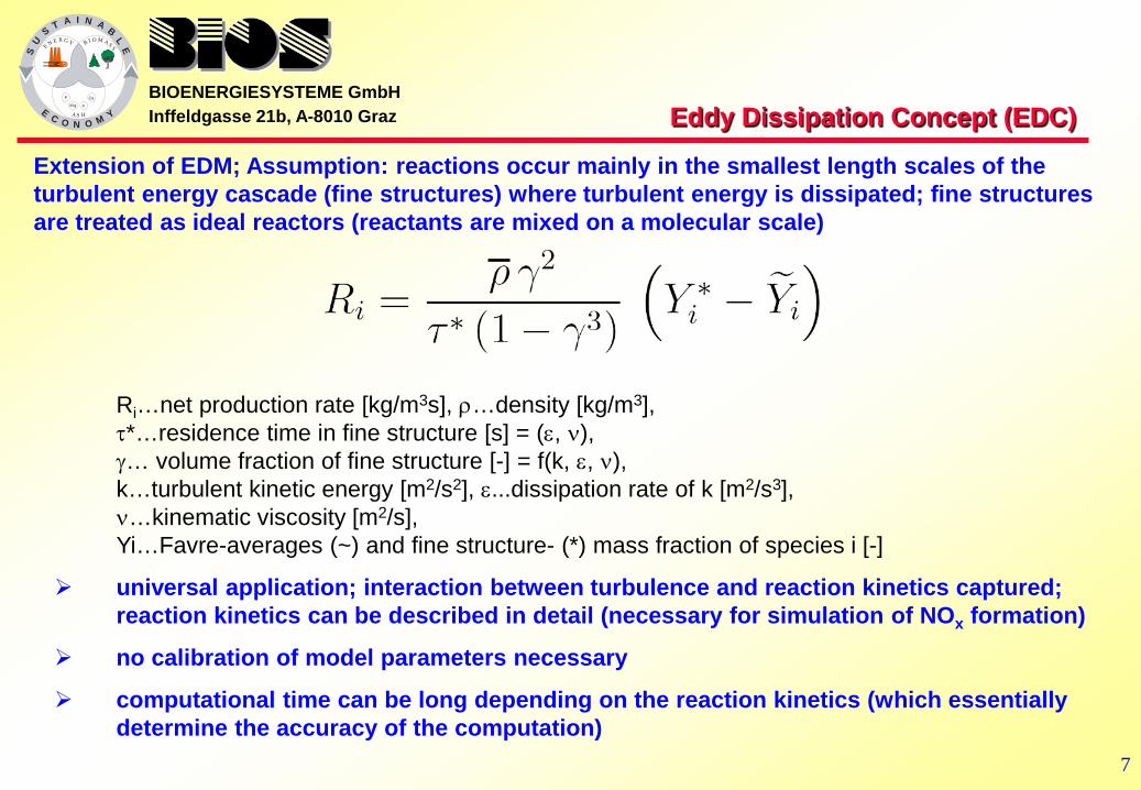
Eddy Dissipation Concept (EDC)
Extension of EDM; Assumption: reactions occur mainly in the smallest length scales of the turbulent energy cascade (fine structures) where turbulent energy is dissipated; fine structures are treated as ideal reactors (reactants are mixed on a molecular scale)
Ri…net production rate [kg/m3s], ρ…density [kg/m3], τ*…residence time in fine structure [s] = (ε, ν), γ… volume fraction of fine structure [-] = f(k, ε, ν), k…turbulent kinetic energy [m2/s2], ε...dissipation rate of k [m2/s3], ν…kinematic viscosity [m2/s], Yi…Favre-averages (~) and fine structure- (*) mass fraction of species i [-]
universal application; interaction between turbulence and reaction kinetics captured; reaction kinetics can be described in detail (necessary for simulation of NOx formation)
no calibration of model parameters necessary
computational time can be long depending on the reaction kinetics (which essentially determine the accuracy of the computation)

BIOENERGIESYSTEME GmbH Inffeldgasse 21b, A-8010 Graz
SU
ST A I N A B
LE
EC O N O M Y
P Ca
KM g
E N E R G Y B I O M A S S
A S H
8
inlet of secondary air
CFD model geometry basic variant
false air, via fuel supply
fuel bed, primary air
exit from boiler
secondary air nozzles
fire tubes
vertical arch
horizontal arch
primary combustion zone secondary
combustion zone

BIOENERGIESYSTEME GmbH Inffeldgasse 21b, A-8010 Graz
SU
ST A I N A B
LE
EC O N O M Y
P Ca
KM g
E N E R G Y B I O M A S S
A S H
9
Basic operating conditions Grass pellets composition
Parameter Unit Grass pelletsbasic
C [wt.% (d.b.)] 48.17
H [wt.% (d.b.)] 6.82
O [wt.% (d.b.)] 31.83
N [wt.% (d.b.)] 5.77
S [wt.% (d.b.)] 0.69
ash [wt.% (d.b.)] 6.72
moisture [wt.% (w.b.)] 10.81
GCV (analysed) [MJ/kg (d.b.)] 21.20
GCV (Gaur) [MJ/kg (d.b.)] 21.40NCV [MJ/kg (w.b.)] 17.30

BIOENERGIESYSTEME GmbH Inffeldgasse 21b, A-8010 Graz
SU
ST A I N A B
LE
EC O N O M Y
P Ca
KM g
E N E R G Y B I O M A S S
A S H
10
Basic operating data
Parameter UnitGrass pelletsbasic
Adiabatic flue gas temperature [°C] 1,361 Fuel power (related to NCV) [kW] 432 Flue gas in combustion chamber - total [kg/h] 949 - Flue gas release from fuel [kg/h] 85 - Combustion air - total [kg/h] 864 Primary air (below grate) [kg/h] 403 Secondary air (nozzles) [kg/h] 461 recirculated flue gas [kg/h] -Primary stoichiometric ratio [-] 0.84Total stoichiometric air ratio [-] 1.67O2 fraction at combustion chamber outlet, dry [Vol% (d.b.)] 8.4

BIOENERGIESYSTEME GmbH Inffeldgasse 21b, A-8010 Graz
SU
ST A I N A B
LE
EC O N O M Y
P Ca
KM g
E N E R G Y B I O M A S S
A S H
11
TFN-release rates for different biomass fuels
explanation: all data taken from reactor experiments with lab-scale pot furnace; TFN … mass of all N-moles contained in NO, NH3, NO2, HCN und N2O, released from the fuel bed
0102030405060708090
100
0.0 0.5 1.0 1.5 2.0 2.5 3.0 3.5 4.0 4.5 5.0 5.5 6.0 6.5 7.0
N content in the fuel [wt%]
Con
vers
ion
rate
of N
to T
FN
straw p. II straw p.soft wood p. soft wood + 20% bark p.bark beechpoplar p. waste woodsawdust MDF IIMDF CardoonCardoon p. ArundoArundo p. MiscanthusMiscanthus p. Miscanthus IIMiscanthus II p. SwitchgrassSwitchgrass p. strawcereals cereals p.grass pellets corncobs

BIOENERGIESYSTEME GmbH Inffeldgasse 21b, A-8010 Graz
SU
ST A I N A B
LE
EC O N O M Y
P Ca
KM g
E N E R G Y B I O M A S S
A S H
12
Results of basic analysis – temperatures and O2 concentrations
Iso-surfaces of temperatures [°C] (left) and O2 concentrations [m³ O2/ m³ wet flue gas] (right) in the symmetry plane of the combustion chamber and the boiler
BIOENERGIESYSTEME GmbH Inffeldgasse 21b, A-8010 Graz
SU
ST A I N A B
LE
EC O N O M Y
P Ca
KM g
E N E R G Y B I O M A S S
A S H
13
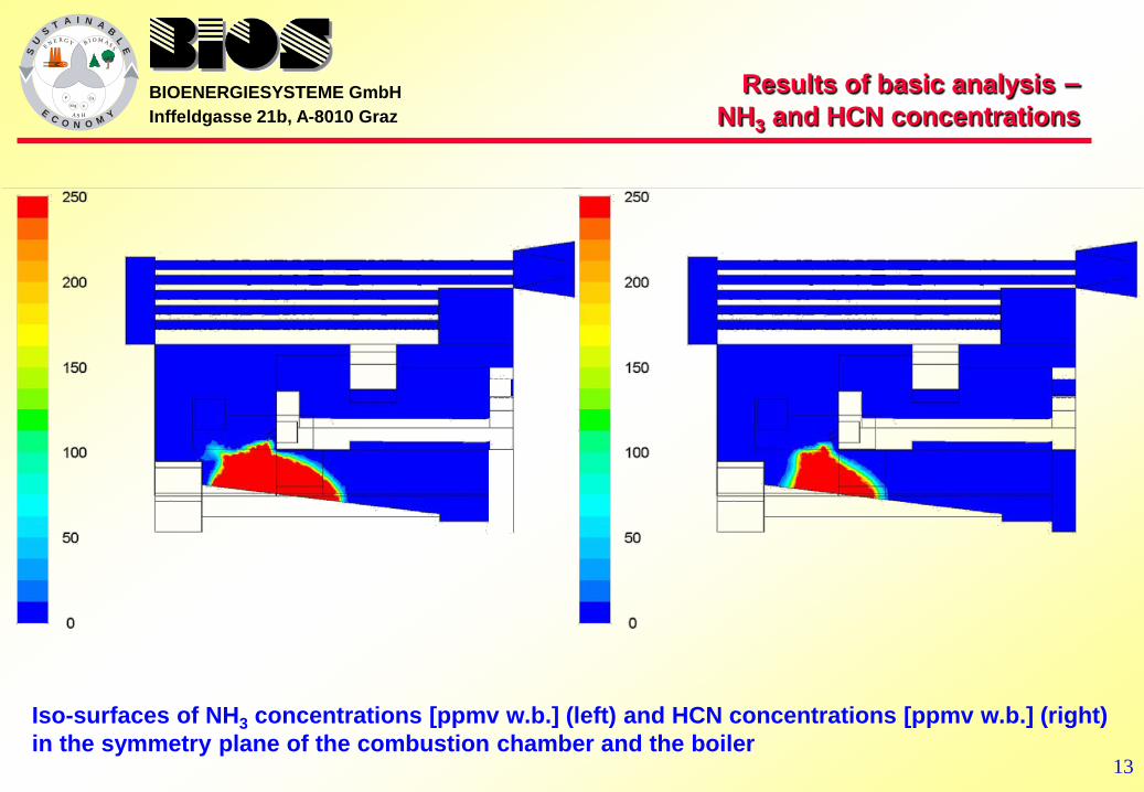
Results of basic analysis – NH3 and HCN concentrations
Iso-surfaces of NH3 concentrations [ppmv w.b.] (left) and HCN concentrations [ppmv w.b.] (right) in the symmetry plane of the combustion chamber and the boiler
BIOENERGIESYSTEME GmbH Inffeldgasse 21b, A-8010 Graz
SU
ST A I N A B
LE
EC O N O M Y
P Ca
KM g
E N E R G Y B I O M A S S
A S H
14
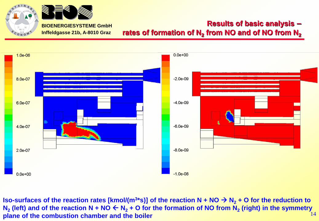
Results of basic analysis – rates of formation of N2 from NO and of NO from N2
Iso-surfaces of the reaction rates [kmol/(m3*s)] of the reaction N + NO N2 + O for the reduction to N2 (left) and of the reaction N + NO N2 + O for the formation of NO from N2 (right) in the symmetry plane of the combustion chamber and the boiler

BIOENERGIESYSTEME GmbH Inffeldgasse 21b, A-8010 Graz
SU
ST A I N A B
LE
EC O N O M Y
P Ca
KM g
E N E R G Y B I O M A S S
A S H
15
Results of basic analysis – NOx concentrations and TFN/TFNin ratio
Iso-surfaces of NOx concentrations [ppmv w. b.] in the symmetry plane of the combustion chamber and the boiler explanations: NOx concentrations as sum of NO, NO2 and N2O concentrations, all in [ppmv w. b.]
Iso-surfaces of local TFN/TFNin ratios in the symmetry plane of the combustion chamber and the boiler explanation: all data taken from reactor experiments with lab-scale pot furnace; TFN … mass of all N-moles contained in NO, NH3, NO2, HCN und N2O, released from the fuel bed
837 mg/Nm³ dry flue gas; 13 Vol% O2

BIOENERGIESYSTEME GmbH Inffeldgasse 21b, A-8010 Graz
SU
ST A I N A B
LE
EC O N O M Y
P Ca
KM g
E N E R G Y B I O M A S S
A S H
16
Results of basic analysis – Evaluation
Evaluation of basic analysis:
Small primary combustion zone (small flue gas residence time for reduction)
thermal NOx (high local flue gas temperatures)
Measures taken for optimization:
new position of secondary air nozzles
flue gas recirculation (temperature control)

BIOENERGIESYSTEME GmbH Inffeldgasse 21b, A-8010 Graz
SU
ST A I N A B
LE
EC O N O M Y
P Ca
KM g
E N E R G Y B I O M A S S
A S H
17
Basic and optimized operating conditions Grass pellets composition
Parameter Unit Grass pelletsbasic
Grass pelletsoptimised
C [wt.% (d.b.)] 48.17 49.23
H [wt.% (d.b.)] 6.82 6.53
O [wt.% (d.b.)] 31.83 30.41
N [wt.% (d.b.)] 5.77 5.47
S [wt.% (d.b.)] 0.69 0.65
ash [wt.% (d.b.)] 6.72 6.80
moisture [wt.% (w.b.)] 10.81 11.18
GCV (analysed) [MJ/kg (d.b.)] 21.20 21.20
GCV (Gaur) [MJ/kg (d.b.)] 21.40 21.46
NCV [MJ/kg (w.b.)] 17.30 17.28

BIOENERGIESYSTEME GmbH Inffeldgasse 21b, A-8010 Graz
SU
ST A I N A B
LE
EC O N O M Y
P Ca
KM g
E N E R G Y B I O M A S S
A S H
18
Basic and optimized operating data
Parameter UnitGrass pelletsbasic
Grass pellets
optimisedAdiabatic flue gas temperature [°C] 1,361 1,042 Fuel power (related to NCV) [kW] 432 370 Flue gas in combustion chamber - total [kg/h] 949 1,126 - Flue gas release from fuel [kg/h] 85 72 - Combustion air - total [kg/h] 864 753 Primary air (below grate) [kg/h] 403 362 Secondary air (nozzles) [kg/h] 461 391 recirculated flue gas [kg/h] - 301 Primary stoichiometric ratio [-] 0.84 0.79Total stoichiometric air ratio [-] 1.67 1.64effective stoichiometric ratio on grate(1) [-] 0.91effective stoichiometric ratio on grate(2) [-] 1.03ratio of recirculated flue gas below grate [-] - 0.52flue gas recirculation ratio [-] - 0.27O2 fraction at combustion chamber outlet, dry [Vol% (d.b.)] 8.4 8.3

BIOENERGIESYSTEME GmbH Inffeldgasse 21b, A-8010 Graz
SU
ST A I N A B
LE
EC O N O M Y
P Ca
KM g
E N E R G Y B I O M A S S
A S H
19 19
inlet of secondary air
secondary air nozzles (2x6;
18 mm) flue gas
recirculation nozzles (11; 18 mm)
fuel bed, primary air, flue gas recirculation
bis zur Decke verlängerte stirnseitige Schamottauskleidung
additional lining
additional lining
CFD model geometry optimised variant

BIOENERGIESYSTEME GmbH Inffeldgasse 21b, A-8010 Graz
SU
ST A I N A B
LE
EC O N O M Y
P Ca
KM g
E N E R G Y B I O M A S S
A S H
20
Results of optimization – NOx concentrations
grass pellets grass pellets basic geometry optimized geometry basic operating conditions optimized operating conditions
Iso-surfaces of NOx concentrations [ppmv w. b.] in the symmetry plane of the combustion chamber and the boiler explanations: NOx concentrations as sum of NO, NO2 and N2O concentrations, all in [ppmv w. b.]
837 mg/Nm³ dry flue gas; 13 Vol% O2 525 mg/Nm³ dry flue gas; 13 Vol% O2

BIOENERGIESYSTEME GmbH Inffeldgasse 21b, A-8010 Graz
SU
ST A I N A B
LE
EC O N O M Y
P Ca
KM g
E N E R G Y B I O M A S S
A S H
21
0.19 0.11
Results of optimization – TFN/TFNin ratios
grass pellets grass pellets basic geometry optimized geometry basic operating conditions optimized operating conditions
Iso-surfaces of local TFN/TFNin ratios in the symmetry plane of the combustion chamber and the boiler explanation: TFN … mass of all N-moles contained in NO, NH3, NO2, HCN und N2O, released from the fuel bed

BIOENERGIESYSTEME GmbH Inffeldgasse 21b, A-8010 Graz
SU
ST A I N A B
LE
EC O N O M Y
P Ca
KM g
E N E R G Y B I O M A S S
A S H
22
Results of optimization – measurement compared to simulation results
UnitGrass pellets
optimisedsimulated NOx-emissions (calculated
as NO2) at the boiler exitmg NOx/Nm³ dry fuel
gas; 13 Vol.% O2 525
measured NOx-emissions mg NOx/Nm³ dry fuel
gas; 13 Vol.% O2 572

BIOENERGIESYSTEME GmbH Inffeldgasse 21b, A-8010 Graz
SU
ST A I N A B
LE
EC O N O M Y
P Ca
KM g
E N E R G Y B I O M A S S
A S H
23
Summary and conclusions
3D simulations of biomass grate furnaces with the CFD NOx post-processor including detailed chemistry have been performed.
Detailed information of NOx formation and reduction in grate combustion plants as well as a relevant influencing parameters can be gained.
Good qualitative and semi-qualitative agreement of simulation results with measurements achieved for different biomass fuels.
The NOx postprocessor for biomass grate furnaces is a powerful tool for the design and optimisation of furnace geometries and process control in order to optimize NOx reduction by primary measures.

BIOENERGIESYSTEME GmbH Inffeldgasse 21b, A-8010 Graz
SU
ST A I N A B
LE
EC O N O M Y
P Ca
KM g
E N E R G Y B I O M A S S
A S H
24
Thank you for your attention
Mag. Dr. Claudia Benesch Inffeldgasse 21b, A-8010 Graz, Austria
TEL.: +43 (316) 481300-61; FAX: +43 (316) 4813004 Email: [email protected]
HOMEPAGE: http://www.bios-bioenergy.at