Embed Size (px)
Citation preview

Computers & Fluids 102 (2014) 62–73
Contents lists available at ScienceDirect
Computers & Fluids
journal homepage: www.elsevier .com/locate /compfluid
CFD simulation of confined non-premixed jet flames in rotary kilnsfor gaseous fuels
http://dx.doi.org/10.1016/j.compfluid.2014.05.0330045-7930/� 2014 Elsevier Ltd. All rights reserved.
⇑ Corresponding author at: Mechanical Engineering Department, Faculty ofEngineering, King Abdulaziz University, North Jeddah, 21589 Jeddah, Kingdom ofSaudi Arabia. Tel.: +966 501531215.
E-mail address: [email protected] (H.F. Elattar).
H.F. Elattar a,b,⇑, Rayko Stanev c, Eckehard Specht d, A. Fouda e
a Mechanical Engineering Department, Faculty of Engineering, King Abdulaziz University, North Jeddah, 21589 Jeddah, Kingdom of Saudi Arabiab Mechanical Engineering Department, Faculty of Engineering, Benha University, Benha, 13511 Qalyubia, Egyptc University of Chemical Technology and Metallurgy – Sofia, 8 St. Kliment Ohridski Blvd., 1756 Sofia, Bulgariad Institute of Fluid Dynamics and Thermodynamics, Otto von Guericke University Magdeburg, Universitätsplatz 2, 39106 Magdeburg, Germanye Mechanical Power Engineering Department, Faculty of Engineering, Mansoura University, 35516 El-Mansoura, Egypt
a r t i c l e i n f o
Article history:Received 29 June 2013Received in revised form 26 February 2014Accepted 27 May 2014Available online 25 June 2014
Keywords:Confined jetNon-premixed flameRotary kilnCFD simulation
a b s t r a c t
In the present study, computational fluid dynamics (CFD) methodology is used to investigate the confinednon-premixed jet flames in rotary kilns. Simulations are performed using ANSYS-Fluent, a commercialCFD package. A two-dimensional axisymmetric model is conducted to understand the main operationaland geometrical parameters of rotary kilns, which affect the flame behaviors, including the aerodynamicsand heat transfer. Three kinds of fuels are employed in this study; Methane (CH4), Carbon Monoxide (CO)and Biogas (50% CH4 and 50% CO2). Confined jet flame length correlations are developed and presented interms of kiln operational and geometrical parameters. Previous 2-D simulation results of free jet flamesare used to select and validate the turbulence model, which applied in this study. The present simulationresults are compared with available experimental data and previous analytical results, which show sat-isfactory agreement.
� 2014 Elsevier Ltd. All rights reserved.
1. Introduction
Rotary kilns have been used successfully for many years inindustrial processes and have continuously improved over the cen-tury. It has applied to many applications such as calcinations oflimestone, cement industry, metallurgy and incineration of wastematerials. It is pyroprocessing devices, which used to raise thetemperature of materials (calcinations) to high values in a contin-uous method. In the pyroprocessing technique, materials are sub-jected to high temperatures (typically over 800 �C), hence achemical or physical change might be occurred [1]. Moreover, itcan be employed for many industrial processes such as incinera-tion, mixing, roasting, cooling, humidification, sintering, melting,gasification, dehydration and gas–solid reactions [2]. This isbecause the rotary kilns are able to operate at high burning zonetemperature, for example; lime burning (1200 �C) [3], burning ofcement clinker (2000 �C) and calcinations of petroleum coke(1100 �C) [4] and calcinations of aluminum oxide (1300 �C) [5,6].
However, cement industry is considered one of the most commonapplications of rotary kilns [7].
Another essential application of rotary kilns is the incinerationof waste materials [8]. It can handle a wide variety of feed materi-als with variable calorific value and burn the solid wastes at theexit without any problems. Typically, hazardous waste incineratorsoperate with relatively deep beds and have a secondary combus-tion chamber after rotary kiln to improve the heterogeneous com-bustion of wastes [9]. It used to gasify the waste tires or wood toobtain activated carbon [10,11]. Furthermore, it used to clean upsoil that has been contaminated with hazardous chemicals in aprocess called thermal desorption [12,13]. Consequently, rotarykilns can be used for three purposes: heating, reacting and dryingof solid materials, and in many cases, they are used to achieve acombination of these aims.
CFD simulation methods have been extensively employed toinvestigate the rotary kilns design and its operational parametersover several decades. In the design process of rotary kilns, thereare four important aspects should be considered from a pro-cess-engineering point of view. These aspects are heat transferfrom flame, material flow through the kiln, gas–solid mass trans-fer and reaction [14]. Rate of heat transfer from flame is consid-ered one of the most important factors among the four aspects,

Nomenclatures
D kiln diameter, mda,i air inlet diameter, mdo fuel nozzle diameter, mfo fuel nozzle mean mixture fractionfst stoichiometric mean mixture fraction, fst = 1/(1 + L)L stoichiometric air to fuel mass ratio, kgair/kgfuel
Lf overall confined jet flame length, mR kiln radius, mra,i air inlet radius, mTa axial temperature, �CTair air temperature, �CTo fuel temperature, �Cu mean axial velocity, m/sua axial velocity of the mixture/flame, m/s
uo fuel velocity at the nozzle, m/sv mean radial velocity, m/sw mean tangential velocity, m/sx axial distance from burner, mk excess air numberqo fuel density, kg/m3
qst stoichiometric density (density of combustion gas atstoichiometric mixture fraction), kg/m3
CH4 MethaneCO Carbon MonoxideCO2 Carbon dioxideH2 HydrogenH2O WaterO Oxygen
0 40 80 120 160 200x/do
0
10
20
30
u o/u
a
CH4, free jet,Tair= 20 oC, To= 20 oCAnalytical (R. Jeschar & R. Alt, 1997)Numerical (K-ε, Standard)Numerical (K-ε, RNG)Numerical (K-ε, Realizable)Numerical (K-ω, SST)Numerical (RSM)
Fig. 1. Turbulence model comparisons and validation with analytical axial velocity[17].
H.F. Elattar et al. / Computers & Fluids 102 (2014) 62–73 63
since it has a vital effect on the performance of the rotary kilns.The effective heat transfer rate from flame to solid materialsand flame pattern are strongly related to flame properties, whichin turn have great effect on the kiln efficiency. Moreover, flamecharacteristics such as length, shape and intensity play a crucialrole in improving the operation efficiency of the kiln. Further-more, it strongly affects the rate of heat transfer, hence the fuelconsumption, product quality, total reduced sulfur emissions,nitrogen oxide emissions, and refractory life. On the other hand,the flame pattern plays an essential role in the formation ofmid kiln rings, which have contradictory effect on the kiln effi-ciency and increase its maintenance cost. Moreover, other ther-mal phenomena might be happened and can restrict theperformance of the kilns such as; flame instability that may causea wide variation in gas temperatures, short bushy flame whichcan damage the refractory lining, and lazy flame that might notdeliver an enough heat to complete the reaction. As a result, itis important to optimize the flame characteristics such as shapeand length, which are significantly affected by operational param-eters including fuel type and flow rate [15]. Consequently, con-trolling the kiln flame characteristics is not an easy task due tothe fluctuations in operating parameters that affect the kiln per-formance and its flame [16].
Based on reviewing the previous studies on this research area,much crucial information about the flame length, gas temperaturedistributions and flow visualization inside the rotary kilns, is stillnot completely understood. Moreover, the effects of the inlet airconditions, excess air number, air inlet diameter and radiationeffect on the flame characteristics are rarely investigated. Suchinformation and parameters are very important for efficient designand operation of the rotary kilns. In a pace towards that object, a 2-D simulation study of a confined non-premixed jet flame using gas-eous fuels is performed. A large cylinder has a diameter of 2.6 mand length of 20 m is proposed in the present study to investigatethe effect of kiln geometry and various operating parameters onflame behaviors such as thermal distribution and flow visualiza-tion. The obtained findings are presented in form of centreline axialvelocity profiles, centreline temperature profiles and axial meanmixture fraction profiles to estimate the flame length. In addition,mean mixture fraction and temperature contours are shown tovisualize the flame shape. Such parameters are varied to regulatethe flame length, which controls the thermal processes and con-trols the product quality. Finally, useful design guidelines anddimensionless correlations that characterize the flame length aredeveloped and presented.
2. Computational methodology
2.1. Turbulence model selection and validation
The flame simulation results that obtained from the presentCFD solver are compared and validated with published experimen-tal data and analytical results. Fig. 1 shows a comparison betweenthe present numerical results obtained from different turbulencemodels and analytical solution of axial velocity distribution for freejet flame that presented by Jeschar and Alt [17], which show goodagreement. The figure explains the effect of the turbulence modelused in the present study on the accuracy of simulation resultswhen comparing with the analytical solution of axial velocity pro-file. As can be seen in Fig. 1, the realizable k-e turbulent modelgives the best agreement with the analytical solution among theother employed turbulence models. Fig. 2 shows another compara-ble study that is performed between the present simulation resultsand the experimental data [18] in terms of the axial mixture frac-tion. Similar to the results shown in Fig. 1, the realizable k–e turbu-lent model gives the best agreement with the experimental datacompared to the other turbulence models applied. Furthermore,it can be seen in Fig. 2 that the Reynolds-Stress-Model (RSM) hasapproximately the same behavior of realizable k–e model; how-

0 40 80 120x/do
0
0.2
0.4
0.6
0.8
1Ax
ial m
ixtu
re fr
actio
n, f
a
do= 8 mm, dp= 140 mm,uo= 42.2 m/s, up= 0.3 m/s, Tair= To= 300 K
Num. (k-ε, standard)Num. (k-ε, RNG)Num. (k-ε, realizable)Num. (k-ω, standard)Num. (k-ω, SST)Num. (RSM)Exp. (Sandia, Meier et al., 2000)Exp. (DLR, Meier et al., 2000)
Fig. 2. Turbulence model comparisons and validation with experimental axialmixture fraction [18].
64 H.F. Elattar et al. / Computers & Fluids 102 (2014) 62–73
ever, it is not recommended for the present study since it needsmuch computational time.
2.2. Numerical approach and assumptions
A CFD flow solver based on finite volume method (ANSYS-Flu-ent) is employed in the present study to solve the Reynolds Aver-aged Navier– Stokes (RANS) equations, species transport, energyequation and radiation model. The flow is assumed as steadyand incompressible and the problem is dealt as axi-symmetry.The walls assumed to be adiabatic and the wall type (construc-tion) does not consider in the simulation (i.e. wall heat flux = 0,internal emissivity = 1, and wall thickness = 0) and these assump-tions lead to relative approximate results. Rotation speed, bedpercent fill and buoyancy has no significant effect on the flamebehaviors and its aerodynamics [19]. The steady-state continuityequation of gas phase is stated in Eq. (1). Where the source termSm resulted from fuel injection. The components of velocity in athree-dimensional coordinate system are represented by themomentum equation that is given in Eq. (2). The terms in Eq.(2) include pressure, turbulent shear stresses, gravitational force(buoyancy effects), and the source terms.
@
@xiðquiÞ ¼ Sm ð1Þ
@
@xjðquiujÞ ¼ �
@p@xiþ @sij
@cjþ qgi þ Fi þ Sm ð2Þ
A preliminarily study is conducted using different turbulencemodels to select the appropriate model for the present study thatgives accurate results in compassion with the available experimen-tal and analytical data. As stated in the previous part, the realizablek–e turbulence model showed the best agreement with the exper-imental and analytical data available. The realizable k–e turbulencemodel is derived from the instantaneous Navier–Stokes equations[20], and the term ‘‘realizable’’ means that the model satisfies cer-tain mathematical constraints on the Reynolds stresses and consis-tent with the physics of turbulent flows. The analytical derivationof the realizable k–e turbulence model, its constants and additionalterms and functions in the transport equations for k and e are dif-ferent from those in the standard k–e and RNG k–e models. Thetransport equations for the realizable k–e model are given in Eqs.(3) and (4).
@
@xjðqkujÞ¼
@
@xjlþlt
rk
� �@k@xj
� �þGkþGb�qe ð3Þ
@
@xjðqeujÞ¼
@
@xjlþlt
re
� �@e@xj
� �þqC1Se�qC2
e2
kþffiffiffiffiffimep þC1e
ek
C3eGb ð4Þ
As can be seen in Eqs. (3) and (4), Gk and Gb represent the generationof turbulence kinetic energy due to the mean velocity gradients anddue to buoyancy respectively. C2 and C1e are constants and rk and re
are the turbulent Prandtl numbers for k and e. In the present kilnsimulation, the turbulent intensity for the air inlet is taken as 10%and for the fuel inlet is 5%.
The non-premixed combustion model and Probability DensityFunction (PDF) are chosen for chemical reaction simulation. Thenon-premixed modeling approach offers many benefits over thefinite rate formulation. This model allows intermediate (radical)species prediction, dissociation effects, and rigorous turbulence–chemistry coupling. The method is computationally efficient inthat it does not require the solution of a large number of speciestransport equations. When the underlying assumptions are valid,the non-premixed approach is preferred over the finite rate formu-lation. The non-premixed approach can be used only when thereacting flow system meets several requirements. First, the flowmust be turbulent. Second, the reacting system includes a fuelstream, an oxidant stream, and, optionally, a secondary stream(another fuel or oxidant, or a non-reacting stream). Finally, thechemical kinetics must be rapid so that the flow is near chemicalequilibrium [21].
Owing to the fluctuating properties of a turbulent mixing pro-cess, the Probability Density Function, PDF is a preferred methodfor the cases containing combustion process and turbulent flow.In this study b-PDF model is used because its better results forthe turbulent non-premixed reacting flow in comparing with dif-ferent PDF models [22]. In b-PDF model the PDF is defined bytwo parameters of mean scalar quantity and its variance. Due tothe difficulty in solving the transport equation for each species,the mixture fraction, f in the presumed b-PDF is written in termsof mass fraction of species i, Zi:
f ¼ Zi � Zi;ox
Zi;fuel � Zi;oxð5Þ
The subscripts ‘‘ox’’ and ‘‘fuel’’ denote the value at the oxidizer andfuel stream inlets, respectively. It has a value of one (f = 1) in thefuel stream, zero value (f = 0) in the oxidizer stream and it takes val-ues between zero and one (f = 0–1) within the flow field.
The transport equations of mean mixture fraction, �f and its var-iance, f 02, are:
@
@tðq�f Þþ @
@xjðquj
�f Þ¼ @
@xj
lt
rt
@�f@xj
!ð6Þ
@
@tqf 02� �
þ @
@xjqujf 02� �
¼ @
@xj
lt
rt
@f 02
@xj
!þCglt
@�f@xj
!2
�Cdqek
f 02 ð7Þ
where f 0 ¼ f � �f . The default values for the constants rt, Cg, and Cd
are 0.85, 2.86, and 2.0, respectively. The power of the mixture frac-tion modeling approach is that the chemistry is reduced to one con-served mixture fraction. Under the assumption of chemicalequilibrium, all thermochemical scalars (species fractions, density,and temperature) are uniquely related to the mixture fraction.The instantaneous values of mass fractions, density, and tempera-ture depend solely on the instantaneous mixture fraction, f:
/i ¼ /iðf Þ ð8Þ/i ¼ /iðf ;HÞ ð9Þ
In Eqs. (8) and (9), /i represents the instantaneous species massfraction, density, or temperature in the case of adiabatic and non-

H.F. Elattar et al. / Computers & Fluids 102 (2014) 62–73 65
adiabatic systems, respectively and H is the instantaneous enthalpy.The prediction of the turbulent reacting flow is concerned with pre-diction of the averaged values of fluctuating scalars which obtainedfrom Eqs. (6) and (7). How these averaged values are related to theinstantaneous values depends on the turbulence–chemistry inter-action model. This relation is established by a PDF model as aclosure model when the non-premixed model is used. The Probabil-ity Density Function, written as p(f), can be thought of as the frac-tion of time that the fluid spends in the vicinity of the state f. Themethod applies to mean values of species concentration and tem-perature. The mean mass fraction of species and temperature, �/i,can be computed as:
�/i ¼Z 1
0pðf Þ/iðf Þdf ð10Þ
�/i ¼Z 1
0pðf Þ/iðf ;HÞdf ð11Þ
Eqs. (10) and (11) represent the mean mass fraction of species andtemperature in the case of adiabatic and non-adiabatic systems.
Similarly, the mean time-averaged fluid density, �q, can be com-puted as
1�q¼Z 1
0
pðf Þqðf Þdf ð12Þ
where pðf Þ ¼ f a�1ð1�f Þb�1Rf a�1ð1�f Þb�1df
; a and b are defined as follows:
a ¼ �f�f ð1� �f Þ
f 02� 1
" #ð13Þ
b ¼ ð1� �f Þ�f ð1� �f Þ
f 02� 1
" #ð14Þ
Determination of �/i in the non-adiabatic system thus requires solu-tion of the modeled transport equation for mean enthalpy, H:
@
@tðqHÞ þ r � ðq~vHÞ ¼ r � kt
cprH
� �ð15Þ
The restrictions for non-premixed model are that the uniquedependence of /1 (species mass fractions, density, or temperature)on f requires that the reacting system must meet the followingconditions: The chemical system must be of the diffusion type withdiscrete fuel and oxidizer inlets. Moreover the Lewis number mustbe unity. (This implies that the diffusion coefficients for all speciesand enthalpy are equal, a good approximation in turbulent flow). Inaddition to, when a single mixture fraction is used, the followingconditions must be met: Only one type of fuel is used, and multiplefuel inlets may be included with the same composition; two ormore fuel inlets with different fuel composition are not allowed.Only one type of oxidizer is involved. The oxidizer may consist ofa mixture of species, and the multiple oxidizer inlets may beinvolved with the same composition. Two or more oxidizer inletswith different compositions are not allowed. Finally, the flow mustbe turbulent [21].
The PRESTO and SIMPLE algorithms are employed in the presentstudy for pressure interpolation and pressure–velocity coupling,respectively. The thermal properties of species are given as func-tions of temperature and standard atmospheric pressure(1.013 � 105 Pa). The energy equation is stated in Eq. (16), whichis solved for enthalpy.
@
@xiðqmihÞ ¼
@
@xiCh
@h@xi
� �þ Sh ð16Þ
The source term Sh in the energy equation includes combustion andradiation heat transfer rates:
The P-1 radiation model is used to calculate the flux of the radi-ation inside of the rotary kiln. It is the simplest case among of themore general P–N radiation models that was derived based on theexpansion of the radiation intensity (I) into an orthogonal series ofspherical harmonics [23,24]. Moreover, the model the P-1 modelrequires only a little demand of the Central Processing Unit(CPU) demand and can be applied easily to various complicatedgeometries. It is suitable for applications where the optical thick-ness (aL) is large, where a is the absorption coefficient and L isthe length scale of the domain. The absorption coefficient (a) canbe a function of local concentrations of H2O and CO2, path lengthand total pressure. On the other hand, the Weighted-Sum-of-Gray-Gases model (WSGGM) is chosen for calculating the variableabsorption coefficient as shown in Eq. (17).
�rqr ¼ aG� 4arT4 ð17Þ
The term�rqr can be directly substituted into the energy equa-tion to calculate the heat sources due to radiation.
2.3. Geometry, grid generation and boundary conditions
Fig. 3 shows a schematic diagram for the confined non-pre-mixed flame configurations, which used in the rotary kiln flamesimulation. This configuration is used to investigate the effects ofkiln geometry and various operating parameters on the flame aero-dynamics and flame length. As shown in Fig. 3, a simple burner isused with a variable air inlet area (Aa,i), which can be controlled bychanging air inlet diameter (da,i). The burner has 50 mm diameterand its thermal power ranges from 0.69 to 1.97 MW according tofuel type. The fuel flows with a uniform axial velocity of 30 m/s,temperature of 20 �C and the excess air number (k) is changed from1.1 to 2.5. The excess air number (k) can be defined as the ratiobetween the actual feed air volume and the theoretical needed(stoichiometric value), (e.g. k = 1.2 means that 20 percent morethan the required stoichiometric air is being used). In the presentstudy, three types of fuels are proposed; Methane (CH4), CarbonMonoxide (CO) and Biogas (50% CH4 and 50% CO2), because theyhave a wide range of stoichiometric air to fuel ratio. Fig. 4(a) and(b) show the 2-D domain geometry and generated mesh of therotary kiln respectively. The full domain geometry is consideredas a symmetrical kiln (20 m length and 2.6 m diameter) to simulateand investigate the effect of confinements on the flame behavior.As shown in Fig. 4(a), half portion of the kiln has been taken forthe present simulation as a studied domain to reduce the compu-tational cost. The mesh of the studied domain is generated by pre-processing package with 30,000 cells, structured and quadrilateralmesh type. The mesh is controlled to be more dense near the bur-ner, where the flame region exists. Moreover, the boundary condi-tions that implemented in the present study are illustrated inFig. 4(b).
2.4. Grid independence study
A number of 2-D meshes are generated with increasing thenumber of cells to perform a grid independent study and to makesure that the flame length converges as the mesh size increases.Fig. 5 illustrates number of 2-D computational grids with differentnumber of cells ranging from 3000 to 100,000 cells that have beentested for flame length convergence. As can be seen, the grids withnumber of cells exceeding than 30,000 cells reveal a small variationin flame length convergence less than 0.2%. Consequently, the gridwith 30,000 cells is recommended to use for accurate calculations.

Fig. 3. Schematic diagram of simulated rotary kiln.
Velocity inlet
Velocity inlet Pressure outletWall
Axi-symmetry
Fig. 4. 2-D domain of investigated rotary kiln flame model: (a) geometry and (b) mesh.
66 H.F. Elattar et al. / Computers & Fluids 102 (2014) 62–73
3. Results and discussion
3.1. Turbulence–chemistry interaction (PDF approach) shortcomings
In order to present the turbulence–chemistry interaction short-comings, Figs. 6–8 show comparisons between the present simula-tion results of the confined jet flame with and without radiationmodeling and the experimental data of Kim [28]. Fig. 6 displays acomparison between numerical simulation results with and with-out radiation modeling and experimental data of Kim et al. [28], atTair = Ta = 300 K do = 2.7 mm, and k = 6.17 for axial temperature ver-sus axial mean mixture fraction. As shown in the figure, thenumerical results give good agreement with experimental data.While, Fig. 7 presents the centreline axial mass fraction distribu-tion of H2 and CO against mean mixture fraction for both simula-tion results and experimental data. As shown in the figure, thenumerical results have the same trend as the experimental results,but with higher values than the experimental data. The discrepan-cies between the experimental data and simulation results areattributed to the inherent simplified assumptions in the turbulence
and combustion models and due to the error in experimental mea-surements. Furthermore, a comparison between the experimentaldata and simulation results of flame length at do = 2.7 mm and4.4 mm at different fuel velocities is demonstrated in Fig. 8. As itcan be seen, the simulation results give satisfactory agreementwith experimental data. The discrepancies in the compared resultsare due to the difference in definition of the flame length, numer-ical assumptions and experimental uncertainty.
In spite of the good overall agreement with the experimental data[28], the shortcomings of the turbulence–chemistry interaction, PDFapproach are apparent. The model tends to underpredict for bothtemperature and mean mixture fraction in axial locations alongthe flame in case of radiation modeling and it gives perfect fit with-out radiation consideration. In case of radiation modeling, the modelpredicts much lower for both temperature and mean mixture frac-tion around the flame end (i.e. around the stoichiometric mean mix-ture fraction value, fst = 0.055), otherwise it gives perfect predictions(near the burner tip; down to fa = 0.3 and downstream the flameend; up to fa = 0.03). Low temperatures are probably caused by over-predicting radiation heat transfer in the radiation model, P-1, and

0 20000 40000 60000 80000 100000Number of Cells
160
180
200
Dim
ensi
onle
ss fl
ame
leng
th (L
f/do)
CH4, λ=1.3without radiation
Tair= To= 20 oC
Fig. 5. Grid independence study for rotary kiln flame length.
0 0.2 0.4 0.6 0.8 1Mixture fraction, f a
0
500
1000
1500
2000
2500
T a (K
)
CH 4, confined jet flame,Tair= 300 K, T o= 300 K, d o=2.7 mm
Num. without radiationNum. with radiationExp. (Kim et al., 2007)
Fig. 6. Comparisons of simulated and experimental data of centreline axialtemperature versus mixture fraction with and without radiation modeling usingMethane flame.
0 0.2 0.4 0.6 0.8 1Mixture fraction, fa
0
0.04
0.08
0.12
0.16
0.2
mas
s fra
ctio
n
CO
H2
CH4, confined jet flame,Tair= 300 K, To= 300 K, do=2.7 mm
Num. with radiationExp. (Kim et al., 2007)
Fig. 7. Comparison of simulated and experimental data of centreline axial massfraction distribution for CO and H2 species versus mixture fraction using Methaneflame.
20 24 28 32
Fuel velocity, u o (m/s)
0
40
80
120
160
Flam
e le
ngth
, Lf (
cm)
do= 4.4 mm
do= 2.7 mm
CH4, confined jet flame,Tair= 300 K, T o= 300 K
Num. with radiationExp. (Kim et al., 2007)
Num. without radiation
Fig. 8. Comparison of simulated and experimental data of flame length versus fuelvelocity at different fuel nozzle diameter using Methane fuel with and withoutradiation modeling.
H.F. Elattar et al. / Computers & Fluids 102 (2014) 62–73 67
low mean mixture fraction may be due to the shortcoming of turbu-lence–chemistry interaction model, PDF approach by underpredict-ing the mixing in the system at high temperatures (around the flameend). Furthermore the model tends to overpredict the mass fractionsof CO and H2 against mean mixture fraction in axial locations alongthe flame, where the model predicts much higher CO and H2. Thismay be caused by the model may be underpredicting the mixingin the system along the flame. In addition to the flame length is over-predicted by the model, where the model predicts much higherflame length at higher fuel nozzle diameter (do = 4.4 mm) and givesperfect fit with experimental data at smaller fuel nozzle diameter(do = 2.7 mm). This may be attributed to the turbulence–chemistryinteraction model shortcomings which cannot predict the mixingprocess in the system perfectly with higher fuel nozzle diameter(i.e. lower jet momentum).
3.2. Effect of excess air number (k)
Fig. 9 explains the effect of excess air number (k) that variesfrom 1 to 2.5 on the dimensionless inverted axial velocity profiles
(uo/ua) using CH4 fuel. As shown in Fig. 9, the axial velocity decaysalong the flame axis and this trend is similar for all the investigatedvalues of the excess air number and for all the selected fuel gases.Moreover, the excess air number has a considerable effect on theaxial velocity profiles, since the axial velocity increases withincreasing the excess air number for all the selected type of fuels.This is due to the fact that the air axial velocity increases withincreasing the excess air number. This effect does not appear inthe entrance region of the kiln, however; it might be reasonablebehavior in fully developed region. In addition to that, the flameconfinement has a significant effect on the flame axial velocity pro-files comparing with free jet profiles. This is because the confinedflame axial velocity is controlled by axial air velocity accordingto the value of the excess air number.
Fig. 10 shows the velocity vectors colored by temperature val-ues to explain the effect of excess air number on the outer recircu-lation zone size for confined Methane jet flame. As shown in thefigure, the recirculation appears at excess air numbers of 1 and1.1 and after that, the recirculation diminishes with increasingthe excess air number. This can be attributed to that the low excessair number has an ambient air momentum less than what the jet
0 100 200 300 400x/do
0
10
20
30
40u o
/ua
CH4, confined jet flame,without radiation,T air=20 oC,
uo= 30 m/s, T o=20 oCλ= 1λ= 1.1λ= 1.3λ= 1.5λ= 1.7λ= 2.0λ= 2.3λ= 2.5free jet
da,i/D= 1
Fig. 9. Influence of excess air number on inverted dimensionless axial velocityprofiles along the flame using Methane fuel.
λ= 1.3
λ= 1.1
CH4
λ= 1.0
Tair= 20 oCTo= 20 oCuo= 30 m/s
da,i/D= 1
[K]
Fig. 10. Influence of excess air number on recirculation zones presented by velocityvectors colored by temperature along the flame using Methane fuel.
0 100 200 300 400
x/do
0
400
800
1200
1600
2000
T a (o C
) CH4, confined jet flame,without radiation,Tair=20 oC,
uo= 30 m/s, To=20 oCλ= 1λ= 1.1λ= 1.3λ= 1.5λ= 1.7λ= 2.0λ= 2.3λ= 2.5free jet
da,i/D= 1
Fig. 11. Influence of excess air number on axial temperature profiles along theflame using Methane flame.
0 50 100 150 200 250x/do
0
10
20
30
f o/f a
CH 4, confined jet flame,without radiation,Tair=20 oC,
uo= 30 m/s, To=20 oCfree jetλ= 2.5λ= 2.3λ= 2.0λ= 1.7λ= 1.5λ= 1.3λ= 1.1λ= 1
fo/fst (CH4)
da,i/D= 1
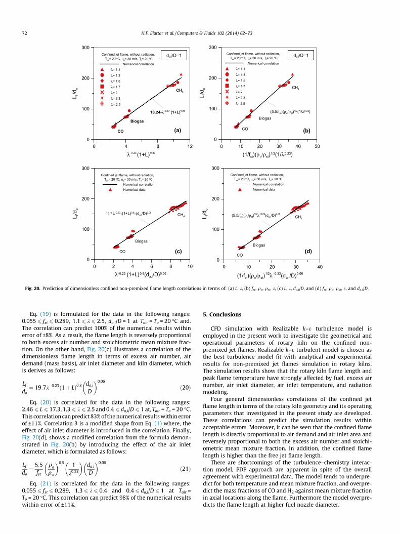
Fig. 12. Influence of excess air number on inverted dimensionless axial meanmixture fraction profiles along the flame using Methane fuel.
68 H.F. Elattar et al. / Computers & Fluids 102 (2014) 62–73
can entrain, hence; the recirculation is commenced. However, athigh excess air number, the ambient air momentum is higherenough to fulfil the requirements for entrainment, hence; the jetwill expand to attach the wall without recirculation. These resultsare matched successfully with that explained by Curtet [25].
The effect of excess air number on the centreline axial temper-ature compared with free jet flame for CH4 fuel is shown in Fig. 11.As it can be seen, the excess air number has a significant effect onthe axial temperature profiles, since the higher the excess air num-ber, the lower the peak flame temperature and product combus-tion gas temperature. This effect appears after x/do � 170. Thefigure explains that the temperature profile approaches to freejet profile with increasing the excess air number. This trend isthe same for all the selected fuel gases, since the mixing tempera-ture between fuel and air decreases with increasing the excess airnumber, hence; a drop in the combustion gas temperature can beobtained.
Fig. 12 illustrates the effect of excess air number on dimension-less inverted axial mixture fraction (fo/fa) profiles for Methane fuel.As shown in the figure, the flame length decreases with increasingthe excess air number and it becomes the same as in free jet atk = 2.5. This is due to that, the higher the excess air number, thehigher amount of oxidizer, hence; the combustion process will becompleted in small volume and consequently in short distance.The same result has been concluded by Yang and Blasiak [26]. Thismeans that the flame length reaches to the smallest possible valueat the highest excess air number, and this effect is the same for allthe studied fuels (e.g., for CH4 fuel the flame length shortens byabout 7% with increasing the excess air number (k) from 1.3 to 2.5).
3.3. Effect of air inlet diameter (da,i/D)
The effects of dimensionless air inlet diameter (da,i/D) on theaxial velocity (ua) and centreline axial temperature (Ta) profilesat different excess air numbers of 1.3, 1.7, and 2.3 using Methanefuel are shown in Figs. 13 and 14 respectively. Fig. 13 explains thatthe axial velocity decreases along the jet flame axis for all the stud-ied values of the air inlet diameter and excess air number. How-ever, at smallest values of air inlet diameter (da,i/D = 0.06 and0.1), the axial velocity increases for awhile, then decreases againalong the jet axis. The possible explanation for this behavior is thatthe axial air velocity around the jet is much higher than the fuel jetvelocity. As a result, the axial air affects the fuel jet velocity byincreasing the centreline axial velocity distribution until it reachesto the maximum value at x/do � 25 and 10 for da,i/D = 0.06 and 0.1,respectively, then the velocity decreases along the jet flame axis.Moreover, the air inlet diameter has a sensible effect on the axialvelocity profiles, whereas the axial velocity profiles shifted up withdecreasing the air inlet diameter until the flow reaches to fully

λ= 1.3
λ= 1.7
0 400x/do
0
1
2
3u a
/uo
CH4, confined jet flame,without radiation, Tair= 20 oC,
uo= 30 m/s, To= 20 oCda,i/D= 0.06da,i/D= 0.1da,i/D= 0.2da,i/D= 0.4da,i/D= 0.5da,i/D= 0.6da,i/D= 0.7da,i/D= 0.8da,i/D= 0.9da,i/D= 1.0
0
100 200 300
100 200 300 400
x/do
0
1
2
3
u a/u
o
CH4, confined jet flame,without radiation, Tair= 20 oC,
uo= 30 m/s, To= 20 oCda,i/D= 0.06da,i/D= 0.1da,i/D= 0.2da,i/D= 0.4da,i/D= 0.5da,i/D= 0.6da,i/D= 0.7da,i/D= 0.8da,i/D= 0.9da,i/D= 1.0
0 100 200 300 400x/do
0
1
2
3
u a/u
o
CH4, confined jet flame,without radiation, Tair= 20 oC,
uo= 30 m/s, To= 20 oCda,i/D= 0.06da,i/D= 0.1da,i/D= 0.2da,i/D= 0.4da,i/D= 0.5da,i/D= 0.6da,i/D= 0.7da,i/D= 0.8da,i/D= 0.9da,i/D= 1.0
λ= 2.3
Fig. 13. Influence of dimensionless air inlet diameter on dimensionless axialvelocity profiles along the flame at different excess air number using Methane fuel.
400x/do
0
400
800
1200
1600
2000
T a (o C
)
CH4, confined jet flame,without radiation, Tair= 20 oC,
uo= 30 m/s, To= 20 oCda,i/D= 0.06da,i/D= 0.1da,i/D= 0.2da,i/D= 0.4da,i/D= 0.5da,i/D= 0.6da,i/D= 0.7da,i/D= 0.8da,i/D= 0.9da,i/D= 1.0
400x/do
0
400
800
1200
1600
2000
T a (o C
)CH4, confined jet flame,
without radiation, Tair= 20 oC, uo= 30 m/s, To= 20 oC
da,i/D= 0.06da,i/D= 0.1da,i/D= 0.2da,i/D= 0.4da,i/D= 0.5da,i/D= 0.6da,i/D= 0.7da,i/D= 0.8da,i/D= 0.9da,i/D= 1.0
0 100 200 300
0 100 200 300
0 100 200 300 400x/do
0
400
800
1200
1600
2000
T a (o C
)
CH4, confined jet flame,without radiation, Tair= 20 oC,
uo= 30 m/s, To= 20 oCda,i/D= 0.06da,i/D= 0.1da,i/D= 0.2da,i/D= 0.4da,i/D= 0.5da,i/D= 0.6da,i/D= 0.7da,i/D= 0.8da,i/D= 0.9da,i/D= 1.0
λ= 1.3
λ= 1.7
λ= 2.3
Fig. 14. Influence of dimensionless air inlet diameter on axial temperature profilesalong the flame at different excess air number using Methane fuel.
H.F. Elattar et al. / Computers & Fluids 102 (2014) 62–73 69
developed flow at x/do � 200, then the effect of air inlet diameterdiminishes. This is because the axial air velocity increases withdecreasing the air inlet diameter, hence; the centreline axial veloc-ity profile increases.
As shown in Fig. 14, the axial temperature distribution and peakflame temperature increase and shift to right with increasing theair inlet diameter. This behavior is the same for the studied valuesof excess air numbers. This can be attributed to the increasinglength of recirculation eddies with decreasing the air inlet diame-ter that in turns improve the mixing process between air and fuel.Consequently, the shorter flame can be obtained and the peakflame temperature is shifted to the burner tip and vice versa. The

[K]
da,i/D= 0.4
da,i/D= 0.6
da,i/D= 0.8
da,i/D= 1.0
λ= 2.3CH4
da,i/D= 0.1uo= 30 m/sTair= 20 oC
Fig. 15. Influence of dimensionless air inlet diameter at k = 2.3 on recirculationzones presented by velocity vectors colored by temperature using Methane fuel.
0 100 200 300 400x/do
0
5
10
15
20
25
f o/f a
fo/fst (CH4)
CH4, confined jet flame,without radiation, Tair= 20 oC,
uo= 30 m/s, To= 20 oCda,i/D= 0.06da,i/D= 0.1da,i/D= 0.2da,i/D= 0.4da,i/D= 0.5da,i/D= 0.6da,i/D= 0.7da,i/D= 0.8da,i/D= 0.9da,i/D= 1.0
λ= 1.3
Fig. 17. Influence of dimensionless air inlet diameter on inverted dimensionlessaxial mean mixture fraction profiles along the flame using Methane fuel at k = 1.3.
70 H.F. Elattar et al. / Computers & Fluids 102 (2014) 62–73
strength and size of those recirculation eddies will affect boththe stability and combustion length of the turbulent diffusionflame [25]. Fig. 15 displays the velocity vectors colored by temper-ature to show the effect of air inlet diameter on the outer recircu-lation zones for Methane jet flame. As shown in the figure, thelength of recirculation decreases with increasing air inlet diameter;this is because of the axial air velocity decreases with increasingthe air inlet area at the same excess air number. In addition to that,the closed part at the air inlet helps the recirculation eddies tooccurs behind it. The effect of the air inlet diameter (da,i) on thetemperature contours is presented in Fig. 16. The figure explainsthat the peak flame temperature increases and shifts to right withincreasing air inlet diameter. This trend is the same for the studiedvalues of excess air numbers. This can be attributed to the increaseof recirculation length increases with decreasing the air inlet diam-eter, which improves the mixing process between air and fuel,hence completing the combustion process in short distance.
On the other hand, the effect of air inlet diameter (da,i) on theinverted dimensionless axial mean mixture fraction (fo/fa) profiles
[K]
da,i/D= 0.1
da,i/D= 0.2
da,i/D= 0.4
da,i/D= 0.5
λ= 2.3CH4
da,i/D= 0.06uo= 30 m/s
Tair= 20 oC
Fig. 16. Influence of dimensionless air inlet diameter on temperature contoursusing Methane fuel at k = 2.3.
is presented in Fig. 17 in order to calculate the flame length usingMethane (CH4) fuel at k = 1.3. As shown in the figure, the flamelength increases with increasing the air inlet diameter and viceversa. This is due to the axial air velocity and length of recirculationeddy increase with decreasing air inlet diameter. However,increasing the air velocity and length of recirculation eddy improvethe mixing process between air and fuel, which result in decreasingthe flame length. Moreover, the changing of dimensionless air inletdiameter (da,i/D) from 0.06 to 0.4 has a considerable effect on theflame length, otherwise it has negligible effect. For instance, theflame length increases by about 180% with increasing the valueof da,i/D from 0.06 to 0.4 and by nearly 6% with increasing the valueof da,i/D from 0.4 to 1 at the same value of excess air number(k = 1.3).
The effect of radiation simulation on the mean mixture fractionand temperature contours of Methane jet flame at k = 1.3 isdepicted in Fig. 18(a) and (b) respectively. As can be seen, radiationmodeling has a considerable effect on the flame length, where the
CH4
λ= 2.3
With radiation
Without radiation
[K]
(a)
Without radiation
With radiation
CH4
λ= 1.3
(b)
Fig. 18. Influence of radiation modeling at Tair = To = 20 �C, uo = 30 m/s, and da,i/D = 1on: (a) temperature contours along the Methane flame at k = 2.3 and (b) meanmixture fraction contours along the Methane flame at k = 1.3.

da,i/D=1
x/do
0
500
1000
1500
2000
2500T a
(o C)
confined jet flame, without radiation, λ= 2.3
Tair= 20 oC, uo= 30 m/s, T o= 20 oCCH4
BiogasCO
CH4
CO
Biogas
(a)
da,i/D=1
0x/do
0
5
10
15
20
25
f o/f a
confined jet flame, without radiation, λ= 2.3
Tair= 20 oC, uo= 30 m/s, To= 20 oC
fo/fs(CH4)
fo/fs(Biogas)
fo/fs(CO)
CH4
CO
Biogas
(b)
da,i/D=1
1 2
0 40 80 120 160 200
40 80 120 160 200
1.2 1.4 1.6 1.8 2.2 2.4
λ
0
5
10
15
20
25
(Lf/d
o) f st
Confined jet flame, without radiation, Tair= 20 oC, uo= 30 m/s, T o= 20 oC
CH4
CO Biogas
dai/D= 1(c)
Fig. 19. Influence of fuel type on: (a) centreline axial temperature profiles, (b)inverted dimensionless axial mean mixture fraction, and (c) flame length trendswith excess air number.
H.F. Elattar et al. / Computers & Fluids 102 (2014) 62–73 71
flame length shortens by about 15% for k = 1.3. This value of reduc-tion in confined jet flame is much higher than the reduction inflame length of free jet Methane flame, which was about 4% at20 �C air temperature [27]. As stated by many authors and proved
by Elattar [27], the flame length does not depend on the fuel veloc-ity, therefore a comparison between CH4, Biogas, and CO is per-formed at constant fuel velocity of 30 m/s and fuel temperatureof 20 �C in order to investigate the flame lengths of gaseous fuels.
Fig. 19(a)–(c), explain the effect of different types of fuels onaxial temperature profiles, inverted axial mean mixture fractionprofiles at excess air number of k = 2.3, and the dimensionless flamelength versus excess air number, respectively. Fig. 19(a) shows acomparison of axial temperature profiles for CH4, Biogas, and COat uo = 30 m/s, Tair = To = 20 �C, da,i/D = 1, and without consideringthe radiation modeling. The figure shows that the Carbon Monoxidefuel (CO) has the highest peak flame temperature of about 1950 �Cat x/do � 41, Biogas fuel has the lowest peak flame temperature ofabout 1550 �C at x/do � 73, while, Methane fuel (CH4) has interme-diate peak flame temperature of about 1800 �C at x/do � 174. Theseresults are approximately the same as in free jet flame simulation at20 �C air temperature, this due to the high value of excess air num-ber, which closes the case from free jet case [27]. On the other hand,Fig. 19(b), illustrates the inverted dimensionless axial mean mix-ture fraction profiles along the flame, in order to calculate the flamelength for the same gases at the same previous conditions. As dis-played in the figure, CH4 has the longest flame length, CO has theshortest flame length, and Biogas is in between of them and theseresults are similar to the free jet simulation results [27]. This canbe attributed to the higher the fuel heating value, the longer theflame length. In other words the lower the fuel stoichiometric meanmixture fraction (fst), the longer the flame length, and vice versa.That means the flame should be spread to reach to its stoichiome-tric mean mixture fraction to end its length. Furthermore, theresults of dimensionless flame length of CH4, Biogas, and CO fuelsat fuel velocity of 30 m/s, air temperature of 20 �C and dimension-less air inlet diameter of da,i/D = 1, without radiation modeling arepresented in Fig. 19(c). As can be seen in the figure, CH4 fuel hasthe longest flame length, then Biogas and finally the CO fuel. More-over, the results explain that the excess air number in the rangefrom 1.1 to 1.5 has a considerable effect on the flame length; other-wise, it has approximately no effect.
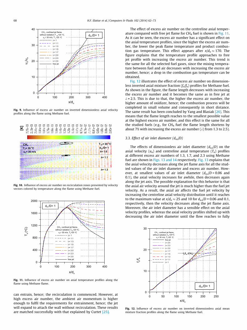
4. Prediction of flame length correlations
Fig. 20(a)–(d) show different predicted correlations of the con-fined flame length in relation with kiln geometry and various oper-ating parameters that employed in the present study. Fig. 20(a)shows the derived dimensionless form of the confined flame lengthin terms of excess air number and air demand (mass basis) asfollows:
Lf
do¼ 18:24k�0:23ð1þ LÞ0:83 ð18Þ
Eq. (18) is formulated for the data in the following ranges:2.46 6 L 6 17.3, 1.1 6 k 6 2.5, and da,i/D = 1 at Tair = To = 20 �C,and. The correlation can predict 100% of the simulation resultswithin error of ±13%. Therefore, the correlation shows that theflame length is directly proportional to air demand and reverselyproportional to excess air number. Moreover, it can be seen that,the confined flame length is higher than the free jet flame length.Another dimensionless formula for the confined flame length interms of stoichiometric mean mixture fraction, fuel density, stoi-chiometric density (density of combustion gas at stoichiometricmixture fraction) and excess air number is presented inFig. 20(b). The predicted formula is derived in the same way ofEq. (1) as follows:
Lf
do¼ 5:5
fst
qo
qst
� �0:5 1k0:23
� �ð19Þ
0 10 20 30 40 50
(1/fst)(ρο/ρst)1/2(1/λ0.23)
0
100
200
300
L f/d
o CH4
Biogas
CO
(5.5/fst)(ρο/ρst)1/2(1/λ0.23)
Confined jet flame, without radiation, Tair= 20 oC, uo= 30 m/s, To= 20 oC
Numerical correlationλ= 1.1
λ= 1.3
λ= 1.5
λ= 1.7
λ= 2
λ= 2.3
λ= 2.5
0 2 4 6 8 10
λ-0.23 (1+L)0.8(da,i/D)0.06
0
100
200
300
L f/d
o
CH4
Biogas
CO
19.7 λ-0.23*(1+L)0.8*(da,i/D)0.06
Confined jet flame, without radiation, Tair= 20 oC, uo= 30 m/s, To= 20 oC
Numerical correlationNumerical data
0 4 8 12
λ-0.23 (1+L)0.83
0
100
200
300
L f/d
o
18.24*λ-0.23 (1+L)0.83
CH4
Biogas
CO
Confined jet flame, without radiation, Tair= 20 oC, uo= 30 m/s, To= 20 oC
Numerical correlationλ= 1.1
λ= 1.3
λ= 1.5
λ= 1.7
λ= 2
λ= 2.3
λ= 2.5
0 10 20 30 40
(1/fst)(ρο/ρst)1/2λ−0.23(da,i/D)0.06
0
100
200
300
L f/d
o
CH4
Biogas
CO
(5.5/fst)(ρο/ρst)1/2λ−0.23(da,i/D)0.06
Confined jet flame, without radiation, Tair= 20 oC, uo= 30 m/s, To= 20 oC
Numerical correlationNumerical data
da,i/D=1da,i/D=1
(a) (b)
(c) (d)
Fig. 20. Prediction of dimensionless confined non-premixed flame length correlations in terms of: (a) L, k, (b) fst, qo, qst, k, (c) L, k, da,i/D, and (d) fst, qo, qst, k, and da,i/D.
72 H.F. Elattar et al. / Computers & Fluids 102 (2014) 62–73
Eq. (19) is formulated for the data in the following ranges:0.055 6 fst 6 0.289, 1.1 6 k 6 2.5, da,i/D = 1 at Tair = To = 20 �C and.The correlation can predict 100% of the numerical results withinerror of ±8%. As a result, the flame length is reversely proportionalto both excess air number and stoichiometric mean mixture frac-tion. On the other hand, Fig. 20(c) illustrates a correlation of thedimensionless flame length in terms of excess air number, airdemand (mass basis), air inlet diameter and kiln diameter, whichis derives as follows:
Lf
do¼ 19:7k�0:23ð1þ LÞ0:8 da;i
D
� �0:06
ð20Þ
Eq. (20) is correlated for the data in the following ranges:2.46 6 L 6 17.3, 1.3 6 k 6 2.5 and 0.4 6 da,i/D 6 1 at, Tair = To = 20 �C.This correlation can predict 83% of the numerical results within errorof ±11%. Correlation 3 is a modified shape from Eq. (1) where, theeffect of air inlet diameter is introduced in the correlation. Finally,Fig. 20(d), shows a modified correlation from the formula demon-strated in Fig. 20(b) by introducing the effect of the air inletdiameter, which is formulated as follows:
Lf
do¼ 5:5
fst
qo
qst
� �0:5 1k0:23
� �da;i
D
� �0:06
ð21Þ
Eq. (21) is correlated for the data in the following ranges:0.055 6 fst 6 0.289, 1.3 6 k 6 0.4 and 0.4 6 da,i/D 6 1 at Tair =To = 20 �C. This correlation can predict 98% of the numerical resultswithin error of ±11%.
5. Conclusions
CFD simulation with Realizable k–e turbulence model isemployed in the present work to investigate the geometrical andoperational parameters of rotary kiln on the confined non-premixed jet flames. Realizable k–e turbulent model is chosen asthe best turbulence model fit with analytical and experimentalresults for non-premixed jet flames simulation in rotary kilns.The simulation results show that the rotary kiln flame length andpeak flame temperature have strongly affected by fuel, excess airnumber, air inlet diameter, air inlet temperature, and radiationmodeling.
Four general dimensionless correlations of the confined jetflame length in terms of the rotary kiln geometry and its operatingparameters that investigated in the present study are developed.These correlations can predict the simulation results withinacceptable errors. Moreover, it can be seen that the confined flamelength is directly proportional to air demand and air inlet area andreversely proportional to both the excess air number and stoichi-ometric mean mixture fraction. In addition, the confined flamelength is higher than the free jet flame length.
There are shortcomings of the turbulence–chemistry interac-tion model, PDF approach are apparent in spite of the overallagreement with experimental data. The model tends to underpre-dict for both temperature and mean mixture fraction, and overpre-dict the mass fractions of CO and H2 against mean mixture fractionin axial locations along the flame. Furthermore the model overpre-dicts the flame length at higher fuel nozzle diameter.

H.F. Elattar et al. / Computers & Fluids 102 (2014) 62–73 73
References
[1] http://en.wikipedia.org/wiki/Rotary kiln.[2] Jauhari R, Gray MR, Masliyah JH. Gas–solid mass transfer in a rotating drum.
Can J Chem Eng 1998;76(2):224–32.[3] Georgallis M. Mathematical modeling of lime kilns, Ph.D. dissertation.
Vancouver (BC): The University of British Columbia; 2004.[4] Peray KE. The rotary cement kiln. New York: Chemical Publishing Co.; 1972.[5] Manitius A, Kureyuz E, Kawecki W. Mathematical model of the aluminium
oxide rotary kiln. Ind Eng Chem Process Des Develop 1974;13(2):132–42.[6] Bui RT, Simard G, Charette A, Kocaefe Y, Perron J. Mathematical modeling of the
rotary coke calcining kiln. Can J Chem Eng 1995;73(4):534–45.[7] http://www.smidth.com.[8] Rovaglio M, Manca D, Biardi G. Dynamic modeling of waste incineration plants
with rotary kilns: comparisons between experimental and simulation data.Chem Eng Sci 1998;53(15):2727–42.
[9] Abe I, Fukuhara T, Iwasaki S, Yasuda K, Nakagawa K, Iwata Y, et al.Development of a high density carbonaceous adsorbent from compressedwood. Carbon 2001;39(10):1485–90.
[10] San Miguel G, Fowler GD, Dall’Orso M, Sollars CJ. Porosity and surfacecharacteristics of activated carbons produced from waste tyre rubber. J ChemTechnol Biotechnol 2002;77(1):1–8.
[11] Ortiz OA, Sua’rez GI, Nelson A. Dynamic simulation of a pilot rotary kiln forcharcoal activation. Comput Chem Eng 2005;29(8):1837–48.
[12] Cook CA, Cundy VA. Study of parameters influencing wall-to-bed heat transferin low-temperature rotary desorbers. J Energy Resour Technol, Trans ASME1995;117(1):50–7.
[13] Rensch T. Beitrag zum Prozess der thermischen Bodendekontamination imDrehrohrofen, Ph.D. dissertation. Germany: The University of Magdeburg;2001.
[14] Barr P. Heat transfer processes in rotary kilns, Ph.D. dissertation. Vancouver(BC): The University of British Columbia; 1986.
[15] Kolev D, Stefanov B, Borisov D, Choshnova D. Method for numerical simulationand graphical presentation of the rate field in a physical model of flashsmelting furnaces. J UCTM 2003;38(4):1147–54.
[16] Aloqaily A. A study of aerodynamics in rotary kilns with two burners, Ph.D.dissertation. Canada: The University of Toronto; 2008.
[17] Jeschar R, Alt R. Ähnlichkeitstheoretische Herleitung der Gesetze für denunverdrallten, isothermen Freistrahl. Institut für Energieverfahrenstechnikund Brennstofftechnik, TU Clausthal; 1997.
[18] Meier W, Barlow RS, Chen Y, Chen J. Raman/Rayleigh/life measurements in aturbulent ch4/h2/n2 jet diffusion flame: experimental techniques andturbulence–chemistry interaction. Combust Flame 2000;123(3):326–43.
[19] Moles PBLFD, Watson D. The aerodynamics of the rotary cement kiln. J InstFuel 1973:353–62.
[20] Shih TH, Liou WW, Shabbir A, Yang Z, Zhu J. A new k–e eddy viscosity model forhigh Reynolds number turbulent flows. Comput Fluids 1995;24(3):227–38.
[21] F. Inc., FLUENT 6.3 User’s Guide, Tutorial Guide, FLUENT User Services Center.Lebanon (NH): Fluent Inc.; 2006.
[22] Poinsot T, Veynante D. Theoretical and numerical combustion. Philadelphia(PA): R.T. Edwards, Inc.; 2001.
[23] Cheng P. Two-dimensional radiating gas flow by a moment method. AIAA J1964;2:1662–4.
[24] Siegel R, Howell JR. Thermal radiation heat transfer. Washington(DC): Hemisphere Publishing Corporation; 1992.
[25] Curtet R. Confined jets and recirculation phenomena with cold air. CombustFlame 1958;2(4):383–411.
[26] Yang W, Blasiak W. Chemical flame length and volume in liquefied propanegas combustion using high-temperature and low-oxygen-concentrationoxidizer. Energy Fuels 2004;18(5):1329–35.
[27] Elattar HF. Flame simulation in rotary kilns using computational fluiddynamics, Ph.D. dissertation. Germany: Magdeburg University; 2011.
[28] Kim HK, Kim Y, Lee SM, Ahn KY. Studies on combustion characteristics andflame length of turbulent oxy-fuel flames. Energy Fuels 2007;21(3):1459–67.