Embed Size (px)
DESCRIPTION
cfd
Citation preview

© 2013 ANSYS, Inc. December 12, 2013 1 Release 14.5
14. 5 Release
Introduction to ANSYS CFD Professional
Workshop 03 Local Mesh Controls
© 2013 ANSYS, Inc. December 12, 2013 2 Release 14.5
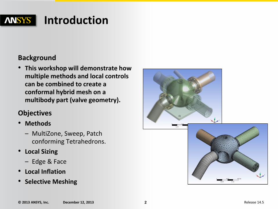
Introduction
Background
• This workshop will demonstrate how multiple methods and local controls can be combined to create a conformal hybrid mesh on a multibody part (valve geometry).
Objectives
• Methods
– MultiZone, Sweep, Patch conforming Tetrahedrons.
• Local Sizing
– Edge & Face
• Local Inflation
• Selective Meshing

© 2013 ANSYS, Inc. December 12, 2013 3 Release 14.5
Starting Workbench Create the Workbench Project:
• From the Workbench File Menu, select Import and browse to the file “valve.meshdat” located in the Meshing Workshops Input-Files folder and open it.
• Start ANSYS Meshing by double clicking on the Mesh Cell (A3) of the Mesh System.

© 2013 ANSYS, Inc. December 12, 2013 4 Release 14.5
Set Global Meshing Options:
• Set Physics Preference to CFD.
• Set Solver Preference to FLUENT.
• In the Units menu set Metric (mm, kg, N, s, mV, Ma)
Units and Preferences

© 2013 ANSYS, Inc. December 12, 2013 5 Release 14.5
Model Review the Geometry:
• The geometry represents a valve with one inlet distributed through a central spherical region to three outlets.
– A mesh will be generated on the fluid region only in this workshop.
• In the Outline expand Geometry, right click on Part2 and select Suppress Body from the Context Menu as shown.
– This will suppress all bodies contained within Part2 which represents the solid outer region in this case. The (transparent) fluid region will be displayed.

© 2013 ANSYS, Inc. December 12, 2013 6 Release 14.5
Preparation Planning
• In the Outline, right click on Mesh and select Show Sweepable Bodies.
– Three of the five bodies could be meshed using the Sweep Method.
– The central region is complex and therefore will be meshed using the Patch Conforming Tetrahedral Method.
– The remaining body cannot be swept using the standard sweep method since it contains multiple source faces as shown. MultiZone will however be able to sweep this.
In the Graphics Window ,
right click View Left or
click the –X Axis on the
Triad to view.

© 2013 ANSYS, Inc. December 12, 2013 7 Release 14.5
Set Global Mesh Options Set up Advanced Size Function:
• To adequately capture the curved geometric features a Curvature Size Function will be used.
• In Details of “Mesh” under Sizing set Use Advanced Size Function to On:Curvature.
• Leave all other options to default as shown.

© 2013 ANSYS, Inc. December 12, 2013 8 Release 14.5
Create Named Selections:
• Switch the view to isometric and ensure the Selection Filter is set to Face.
• Select the face as shown, right click in the Graphics Window and select Create Named Selection from the Context Menu.
• In the Selection Name Dialog Box set the name to “Inlet” and click OK.
Named Selections

© 2013 ANSYS, Inc. December 12, 2013 9 Release 14.5
Create Named Selections (Continued):
• Using the same procedure create Named Selections for the two faces as shown (Outlet1 & Outlet2).
Named Selections
Outlet1
Outlet2

© 2013 ANSYS, Inc. December 12, 2013 10 Release 14.5
Create Named Selections (Continued):
• In the Graphics Window, right click and select View Left (or use the Triad -X). Zoom in as shown.
• Select one of the four small circular faces, right click Create Named Selection.
• In the Selection Name Dialog Box set the name as “Outlet3” and select Apply geometry items of same Size as shown. Click OK.
Named Selections

© 2013 ANSYS, Inc. December 12, 2013 11 Release 14.5
Create Named Selections (Continued):
• In the Outline, expand Named Selections and click on Outline3.
– The worksheet details the method by which the Named Selection is scoped to faces – in this case by size. Switch the worksheet on/off using the Worksheet button in the Toolbar.
– Note that the Named Selection contains all four identical faces.
Named Selections

© 2013 ANSYS, Inc. December 12, 2013 12 Release 14.5
Set up MultiZone for the Non-Sweepable Body:
• Further decomposition at the CAD stage would enable this body to be meshed using the sweep method. However, the Multizone method can be used as an alternative.
• Click Mesh in the Outline.
• Switch the view to isometric , set the Selection Filter to Body and select the non sweepable body as shown.
• Right click Insert Method.
• Under Details of “Automatic-Method” change Method to Multizone.
– The Details view will now be named Details of “Multizone”.
• Leave all other settings to default as shown.
MultiZone Method

© 2013 ANSYS, Inc. December 12, 2013 13 Release 14.5
Insert Face Sizing:
• In the Outline, under Named Selections right click on Outlet3 and click Select Items in Group.
– This will select all the faces contained within that Named Selection.
• In the Outline, right click on Mesh and select Insert Sizing.
– Note that the Details of “Face Sizing” has the Geometry Selection populated with the 4 faces within the Named Selection. You can also use Named Selections directly under Scoping Method.
• Set Element Size to 0.5mm
Local Sizing

© 2013 ANSYS, Inc. December 12, 2013 14 Release 14.5
Local Sizing Insert Edge Sizing:
• Select the Edge Selection Filter.
• The inlet and outlet faces are bound by four edges each.
• Select one edge on each of the four faces as shown (ctrl left click for multiple selection).
• Select Extend to Limits to extend the selection to the complete edge loops.
• In the Outline, right click on Mesh and select Insert Sizing.
• Check that Geometry contains 16 edges.
• Set Element Size to 0.8mm as shown.
1
2
3 4

© 2013 ANSYS, Inc. December 12, 2013 15 Release 14.5
Local Sizing Insert Edge Sizing (Continued):
• A preview of the Edge Sizing will be displayed on the geometry.

© 2013 ANSYS, Inc. December 12, 2013 16 Release 14.5
Local sizing Insert Edge Sizing 2:
• Create another Edge Sizing this time to control the Multizone sweep.
• Select the edge as shown circled and insert sizing as previously.
• Under Details of “Edge Sizing 2” set Element Size to 2.0mm.

© 2013 ANSYS, Inc. December 12, 2013 17 Release 14.5
Sweep Method Insert a Sweep Method:
• The three remaining cylindrical bodies can be swept using the standard sweeper.
• Set the Selection Filter to Body , select the three bodies as shown and right click Insert Method.
• Under Details of “Automatic-Method” change Method to Sweep.
– The Details view will now be named Details of “Sweep Method”.
• Set Type to Element Size and set Sweep Element Size to 2.0mm.

© 2013 ANSYS, Inc. December 12, 2013 18 Release 14.5
Sweep Method Insert a Sweep Method (Continued):
• Set the Source & Target Selection (Src/Trg Selection) to Manual Source.
– If the box adjacent to Source displays “No Selection” with a yellow background click in the yellow box to activate.
• Select the three faces as shown and apply the selection in the box adjacent to Source.
• Check the Details match those shown.

© 2013 ANSYS, Inc. December 12, 2013 19 Release 14.5
Patch Conforming Tetrahedral Method Insert Patch Conforming Tetrahedral Method:
• Use the Body Selection Filter to select the central body as shown.
• Right click Insert Method.
• Under Details of “Automatic-Method” change Method to Tetrahedrons
– The Details view will now be named Details of “Patch Conforming Method”.
• Ensure Algorithm is set to Patch Conforming.

© 2013 ANSYS, Inc. December 12, 2013 20 Release 14.5
Inflation Inflate the MultiZone Method:
• Right click on MultiZone in the Outline and select Inflate This Method from the Context Menu.
• Under Boundary in Details of “Inflation” select the four faces bounding the MultiZone body and apply the selection.
• Set Inflation Option to Total Thickness, Number of Layers to 3 and Maximum Thickness to 1.25mm as shown.
© 2013 ANSYS, Inc. December 12, 2013 21 Release 14.5
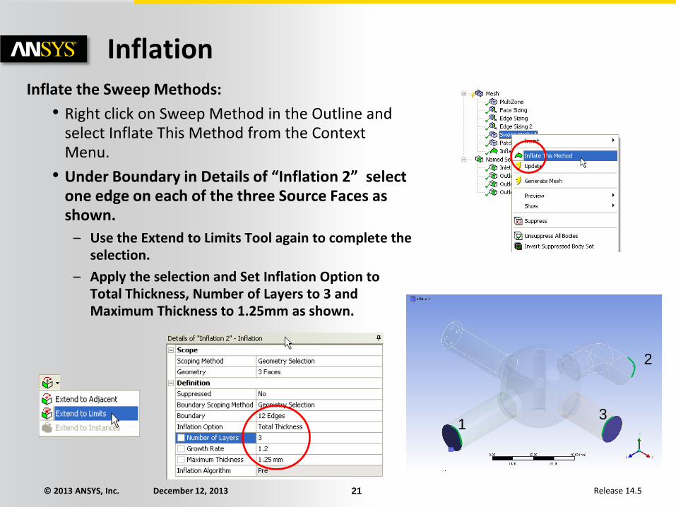
Inflation Inflate the Sweep Methods:
• Right click on Sweep Method in the Outline and select Inflate This Method from the Context Menu.
• Under Boundary in Details of “Inflation 2” select one edge on each of the three Source Faces as shown.
– Use the Extend to Limits Tool again to complete the selection.
– Apply the selection and Set Inflation Option to Total Thickness, Number of Layers to 3 and Maximum Thickness to 1.25mm as shown.
1
2
3

© 2013 ANSYS, Inc. December 12, 2013 22 Release 14.5
Inflation Inflate the Patch Conforming Method:
• Select the four cylindrical bodies, right click in the Graphics Window and select Hide Body.
– This will make boundary selection easier in the next step.
• Right click on Patch Conforming Method in the Outline and select Inflate This Method from the Context Menu.
• Under Boundary in Details of “Inflation 3” all faces of the central body must be selected with the exception of those separating the four cylindrical bodies.

© 2013 ANSYS, Inc. December 12, 2013 23 Release 14.5
Inflation Inflate the Patch Conforming Method (Continued):
• Under Details of “Inflation 3” activate the Boundary Selection Box.
– Apply/Cancel buttons appear when active.
• In the Graphics Window right click and click Select All from the Context Menu.
– All faces will be selected.
• Deselect the four faces as shown by clicking ctrl left click on each face.
– Faces will turn blue when deselected.
• Apply the selection under Details of “Inflation 3” (check 25 Faces are selected).
• Set Inflation Option to Total Thickness, Number of Layers to 3 and Maximum Thickness to 1.25mm as shown.
• In the Graphics Window right click Show All Bodies.
1 2
3 4

© 2013 ANSYS, Inc. December 12, 2013 24 Release 14.5
Selective Meshing Start Selective Meshing:
• When combining multiple mesh methods the order in which the bodies are meshed may influence the final mesh characteristics.
• Generating meshes one by one is called “Selective Meshing”.
• It is therefore required that we can record the body meshing order such that it can be repeated automatically.
• Right click on Mesh in the Outline and select Start Recording from the Context Menu.
• If the Worksheet is displayed switch it off using the worksheet Toggle button.

© 2013 ANSYS, Inc. December 12, 2013 25 Release 14.5
Selective Meshing Generate the MultiZone Mesh:
• Using the Body Selection Filter select the MultiZone body.
• Right click and select Generate Mesh on Selected Bodies.
• The Worksheet will record the operation as Step 1.
• Switch off the Worksheet and view the mesh.
• Note how Multizone has imprinted all source faces onto the target.

© 2013 ANSYS, Inc. December 12, 2013 26 Release 14.5
Selective Meshing
Generate the Sweep Meshes:
• Select the three Sweep mesh bodies.
• Right click and select Generate Mesh on Selected Bodies.
• This operation is again recorded in the Worksheet, this time as Step 2.

© 2013 ANSYS, Inc. December 12, 2013 27 Release 14.5
Selective Meshing Generate the Tetrahedral Mesh:
• Select the central Tetrahedral mesh body.
• Right click and select Generate Mesh on Selected Bodies.
• All three steps are now recorded in the Worksheet.
© 2013 ANSYS, Inc. December 12, 2013 28 Release 14.5
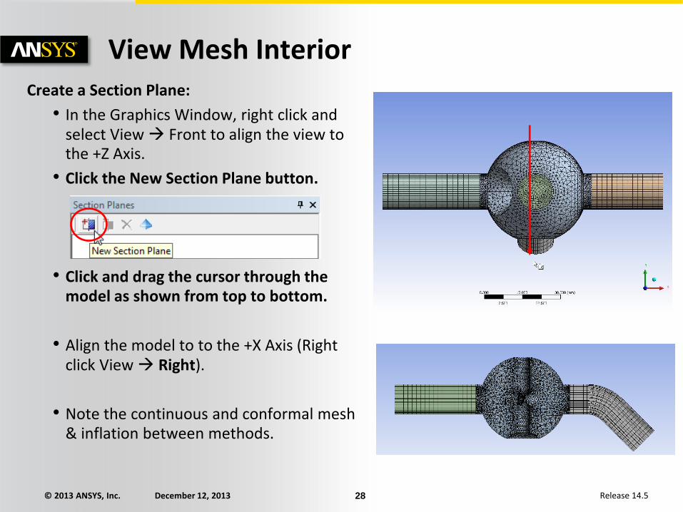
View Mesh Interior Create a Section Plane:
• In the Graphics Window, right click and select View Front to align the view to the +Z Axis.
• Click the New Section Plane button.
• Click and drag the cursor through the model as shown from top to bottom.
• Align the model to to the +X Axis (Right click View Right).
• Note the continuous and conformal mesh & inflation between methods.

© 2013 ANSYS, Inc. December 12, 2013 29 Release 14.5
Create a Section Plane (Continued):
• Align the model to to the -X Axis (Right click View Left).
• Click the New Section Plane button.
• Click and drag the cursor through the model as shown from top to bottom.
• Switch off Section Plane 1 (uncheck Slice Plane 1 in the Section Planes Panel) and restore the view to the +Z Axis (Front).
• Note the swept MultiZone mesh.
• Switch off all Section Planes.
View Mesh Interior
© 2013 ANSYS, Inc. December 12, 2013 30 Release 14.5
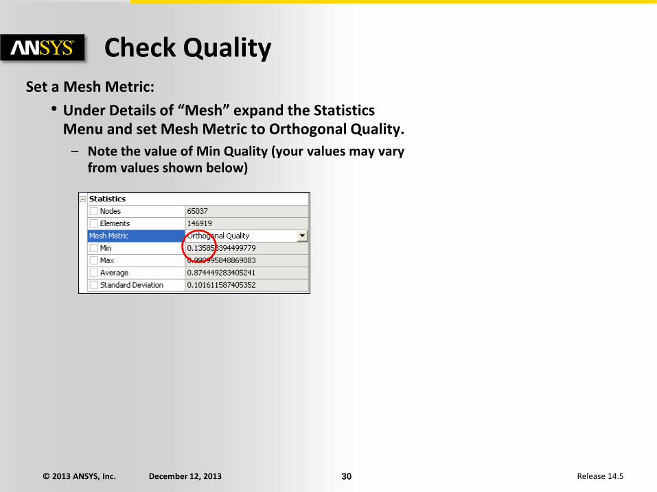
Check Quality Set a Mesh Metric:
• Under Details of “Mesh” expand the Statistics Menu and set Mesh Metric to Orthogonal Quality.
– Note the value of Min Quality (your values may vary from values shown below)

© 2013 ANSYS, Inc. December 12, 2013 31 Release 14.5
Check Quality Use the Mesh Metrics Graph to View Quality Ranges:
• Click the Controls button in the Mesh Metrics Graph and set the Max value for the X-Axis to 0.25. Click Update Y-axis and exit the Controls Panel.
• Select all bars in the Metrics Graph and view the Graphics Window to locate the small number of cells below a quality of 0.25 (Please note that you may have different results for Min & Max quality).

© 2013 ANSYS, Inc. December 12, 2013 32 Release 14.5
• This completes the workshop.
• From the main menu select File Close Meshing
– Workbench will save any application data.
• From the Workbench Project Page use the file menu and save the project as “AMWS3.wbpj” to your working folder.
Save the Project