Embed Size (px)
Citation preview
Abstract—This paper presents a three-dimensional
computational fluid dynamics (CFD) modeling study carried
out for a rotary cement kiln withal multi-channel burner with
swirl and high momentum air components. The simulations are
performed using the commercial CFD software ANSYS
FLUENT, version 13.0, and are carried out for coal as well as
for meat and bone meal (MBM) combustion using the
eddy-dissipation model for combustion. Steady-state solutions
are obtained using the Lagrangian approach for the particle
phase and the Eurasian approach for the continuous phase. The
turbulence is modeled by the RNG k-ε model, and gas-phase
radiation is modeled by the P1 radiation model. The effect of
MBM fuel properties on combustion characteristics such as
temperature, fuel devolatilization, volatiles and char burning,
in comparison with coal, are presented and discussed. It was
found that MBM combustion products temperatureis300K
lower than that of coal, and the char burnout of MBM is 83%.
This poor burnout is mainly due to bigger MBM particles.
Index Terms—CFD, combustion, meat and bone meal, rotary
cement kiln.
I. INTRODUCTION
Typically, cement clinker production requires 3.3-4.0
MJ/kg clinker of thermal energy; depending on the process
[1]. The precalciner and the rotary kiln are the main thermal
energy consuming units in a cement plant. Coal and other
fossil fuels have traditionally been used as fuels in cement
kilns. Nevertheless, because of the high energy cost and high
environmental impact of the process, many cement
companies have turned to energy-rich waste-derived fuels.
The range of waste-derived fuels is extremely wide. Many
plants meet a considerable part of their energy requirements
with waste-derived fuels,for example meat and bone meal
(MBM), waste tires, waste oils, solvents, plastics, paper,
wood, rubber, sewage and refused derived fuels (RDF) [2].
With respect to the global warming scenario, maximum use
of biomass fuels is vital since it gives no net CO2 emissions to
the atmosphere. However, some characteristics ofthose fuels
can impact the kiln process adversely, and may for example
reduceclinker quality, production rate, or kiln refractory life.
Therefore, in order to optimize and control the whole kiln
process, it is important to understand the impacts of such
secondary fuel burning along with the relevancy of their
characteristics.
CFD modelingisa good tool to predict the combustion
Manuscript received April 25, 2014; revised July 1, 2014.
The authors are with Telemark University College, Department of
Process, Energy and Environmental Technology, Faculty of Technology,
Kjølnes Ring 56, Post box 203, N-3901 Porsgrunn, Norway (e-mail:
[email protected], [email protected],
[email protected], [email protected]).
characteristics inside a rotary cement kiln. An overview of
published results from the application of modelingon the
cement kiln process ispresented in the following paragraphs.
A partial differential model has been developed for coal/oil
flame, and the dynamic response has been studied for
different effects, e.g. initial gas temperature, gas velocity and
solids flow rate [3]. A steady state mathematical model for
different zones inside the kiln has been used to predict the
temperature distribution in the solid and gas phases, and also
the composition of former phase [4].
A CFD code has been used to predict flow/combustion
behavior for axisymmetric flow inside a cement kiln for coal
combustion, and temperature, velocity and product
concentration profiles have been calculated [5]. Comparison
of thek-ε model and the Reynolds stress model for turbulence
in pulverized-coal flame in a non-swirling high velocity
cement kiln burner is analyzed and NO emissions have been
predicted [6].
Other authors have employed a comprehensive
mathematical model for a petroleum coke fired non-swirl
burner and have predicted influence of wall temperature,
primary air velocity, secondary air temperature, fuel particle
size, and refractory thickness on ignition, temperature, O2 and
NO concentrations, and heat transfer [7]. In several
publications [8]-[12], flow, mixing patterns, flame length
predictions as well as bed and gas temperature profiles can be
found for coal- combusted cement kilns. The feed bed may be
represented as a moving solid region [11].
In order to quantify energy fluxes from the flame to the
clinker and the heat loss from the kiln, one may model the
coal-fired rotary cement kiln using ax symmetric CFD code
(FLOW-3D) in conjunction with a radiation module
(RAD-3D) [13]. Flame structure, kiln and clinker
temperature distribution and clinker compositions have been
predicted, and the effects of oxygen enrichment and dust
insufflations on kiln parameters have been investigated by
coal combustion simulations with clinker motion and
reactions [14].
2D ax symmetric model predictions for a blend of
bituminous coal and anthracite combustion in a rotary cement
kiln can also be found [15]. Some researchers have developed
a 3D steady state model to predict the flow and heat transfer
in a rotary lime kiln by coupling three sub-models, namely a hot flow model, bed model and wall model [16].
A parameter study of emissivity’s of gas, wall, material,
thickness of brickwork, false air and entraining
characteristics on heat and material flow has also been carried
out [17]. Others have numerically modeled a rotary cement
kiln with combined CFD (Cinar ICE which includes 1D
clinkerization model) and thermo chemical equilibrium
calculations, and incorporation of minor components into the
CFD Modeling of Meat and Bone Meal Combustion in a
Rotary Cement Kiln
W. K. Hiromi Ariyaratne, Anjana Malagalage, Morten C. Melaaen, and Lars-André Tokheim
263
International Journal of Modeling and Optimization, Vol. 4, No. 4, August 2014
DOI: 10.7763/IJMO.2014.V4.384
clinker has been predicted [18]. The commercial 3D CFD
code FLUENT coupled with a 1D heat flux function model
has been used to investigate the pulverized-coal combustion
behavior in a rotary kiln with a four-channel burner, and the
clinker formation has been studied [19].
A 1D reaction engineering model has been developed in
order to simulate key processes in the solid bed of the cement
kiln [20], [21]. Solid-solid reactions, variation of bed height
and melt formation inside the kiln were taken into account.
Bed and gas temperature, clinker composition and factors
affecting the overall energy consumption have been analyzed
and the model has been used to simulate performance of three
industrial kilns. Since a 1D model cannot catch the influence
of burner design and key operating parameters such as
axial:swirl ratio, oxygen enrichment, coal particle size and
ash content on flame characteristics, FLUENT has been used
to couple models for the bed and freeboard regions [22]. Also,
an integrated reaction engineering based mathematical model
and a software (RoCKS) has been developed for the whole
kiln system by same authors [23].
3D simulations for a multi-air channel coal burner has been
carried out using the CFX software, and the effects of air flow
ratios and fuel mean diameter on temperature distribution and
flame features have been presented [24].Others have
developed a multi-fuel CFD code coupled with mineral
reactions (MI-CFD) and presented simulated results for e.g.
temperature and CO and NO concentrations for long
wet-kilns fired with coal, natural gas and whole tires [25].
3D CFD modeling of a full scale rotary cement kiln with a
multi-channel coal burner can be found in another paper, in
which ANSYS FLUENT has been used withal zone-wise
heat flux model to study the effect of swirl angle on
combustion characteristics [26]. An implementation and
validation of the calcinations reaction mechanism of
limestone in a CFD code can also be found [27].
Process simulations of cement kilns can also be found [28,
29], and such simulations have been used to investigate for
example the air and energy demands for MBM and sewage
sludge combustion in rotary cement kilns [28]. A
comprehensive review and evaluation of combustion flame
models can be found in other references [30]-[32].
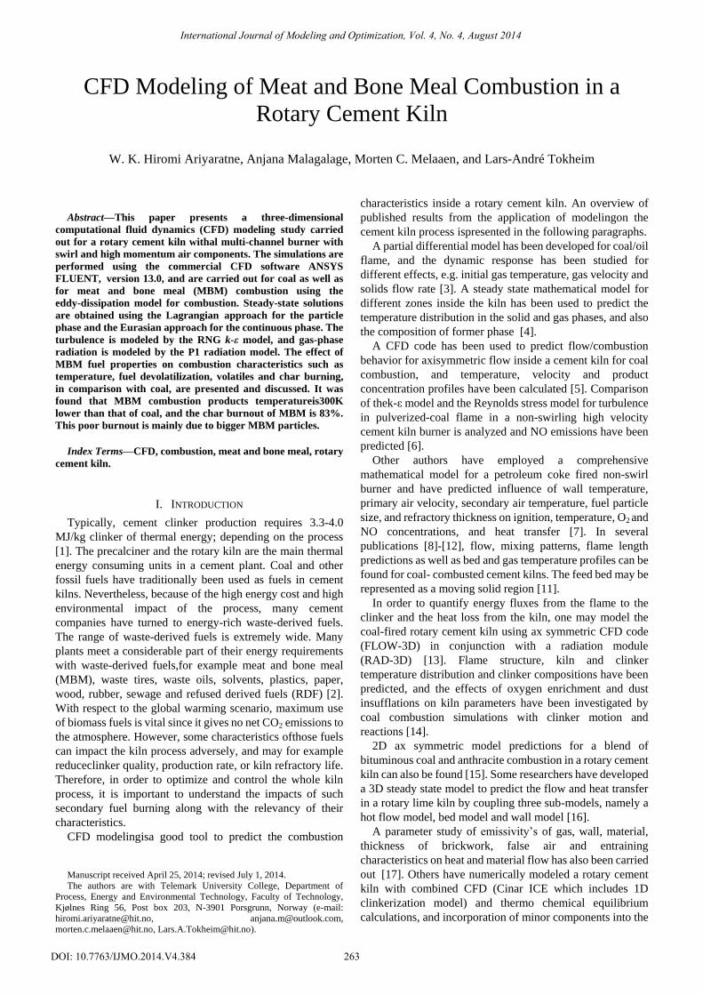
Fig. 1. Dimensions of the real (left) and simplified kiln burner (right).
The review given above shows that there are quite a few
publications available on rotary kiln modeling, and many
different aspects are covered. However, despite the increased
utilization of waste-derived fuels and the impact this may
have on flame properties and kiln performance, very little
information on CFD modeling of combustion of
waste-derived fuels is found in the literature.
In the present study, the commercial CFD software
ANSYS FLUENT, version 13.0, was used for modeling and
simulation of the combustion process inside a rotary cement
kiln. Steady state three-dimensional simulations were carried
out. Process parameters; kiln and burner dimensions were
taken from a full-scale cement plant in Norway which
produces around 3400 tons of clinker per day. Coal was used
as a reference fuel, and MBM, which is 100% biogenic,was
selected as the waste-derived fuel. The effects of MBM fuel
properties on combustion characteristics such as temperature,
fuel devolatilization, volatiles burning and char burning are
presented and discussed. The effect of gravity is also
concerned and discussed. Since the main focus is on the
primary burner combustion process, the solid charge inside
the kiln, the clinker reactions and the kiln rotation are not
considered.
II. GEOMETRY AND GRID GENERATION
A three dimensional 63m kiln was created in Gambit 2.4.6.
Even though, the real kiln is 68m long, the system for the
modeling work is defined from burner tip onwards along the
kiln, since the details are important only from the burner end
onwards.i.e. the 5m of axial distance backward from burner
tip was not calculated, however, the secondary air inlet
boundary conditions of the real kiln was taken as boundary
conditions for the secondary air inlet in the simplified system.
The real rotary kiln burner was somewhat modified to
facilitate modeling (Fig. 1). The 16 swirl air inlets and 20 jet
air inlets were converted to annulus sections; however care
was taken to usea flow area that would conserve not only
mass but also momentum, i.e. the total cross sectional area
of each inlet is similar to each of those in real system. Liquid
hazardous waste and waste oiling lets were discarded since
these are not always used. The solid fuel inlet was moved into
the centre. However, in the present study, the waste derived
264
International Journal of Modeling and Optimization, Vol. 4, No. 4, August 2014
fuel is fed through the coal annulus, not through inner circle
indicated in the figure, in order to rule out the effect of
feeding position (which will be studied separately).The
secondary air is fed through the annular space between the
burner and the kiln inner surface (Ø 0.433 m- Ø 3.920 m).
The kiln and the burner are taken as horizontal.
The geometry and the mesh were generated in Gambit,
version 2.4.6. The mesh is of the Cooper type and consists
ofhexahedral elements. The total number of cells in the mesh
is 335,907.To optimize convergence and computational time,
the grid is finer at the burner area, but coarser at the
secondary air inlet. Gradual increments of cell sizes are used
along the length of the kiln.
III. FUEL AND GAS PROPERTIES
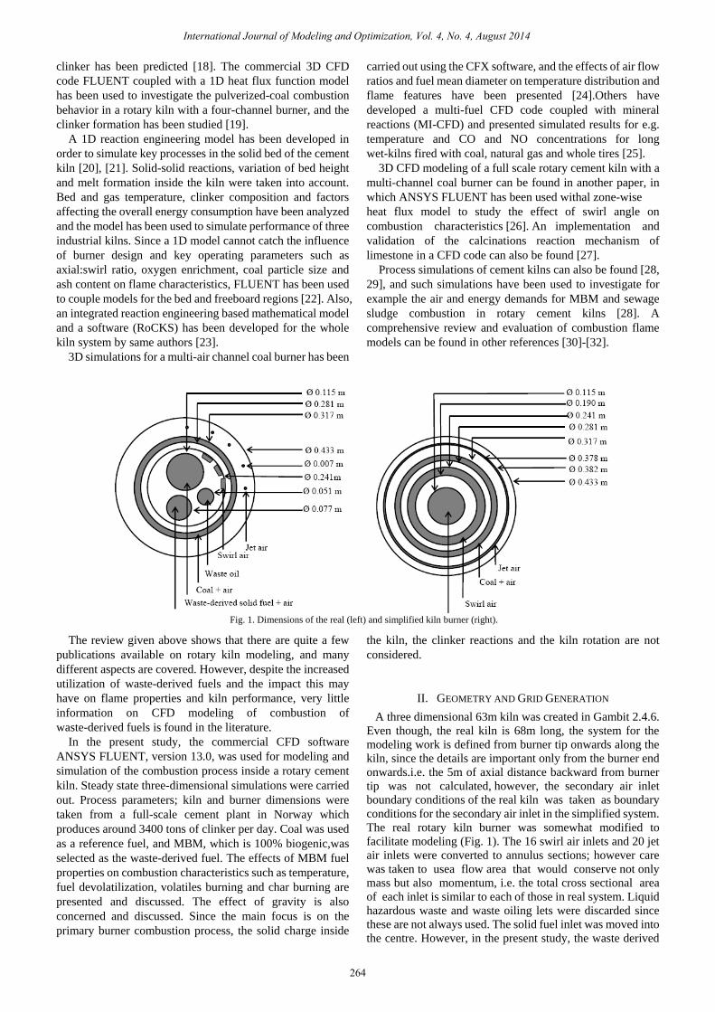
Key fuel and gas properties used in the model are presented
here. The particle size distributions are shown in Fig. 2 and
ultimate analysis, proximate analysis, heating value, dry
particle density [33], [34], water-liquid fraction
anddevolatilization kinetic parameters [35], [36] for the two
fuels are presented in Table I. ANSYS FLUENT default
model parameters are used for char combustion of both fuels
[37]. In plastic coals, such as bituminous coals, formation and
escape of gas-filled bubbles result the swelling of the particle
[38]. The swelling coefficient is defined as 1.4 for coal and 1
for MBM in the present study. In ANSYS FLUENT, the
particles are introduced as a number of uniform surface
injections.
Fig. 2.Particle size distribution of coal and MBM.
TABLE I: PROPERTIES OF FUELS (AS RECEIVED BASIS, UNLESS SPECIFIED)
Property Coal MBM
C (wt%) 72.9 47.1
H (wt%) 3.9 6.9
O (wt%) 5.6 4.5
S (wt%) 1.4 0.5
N (wt%) 1.7 9.7
Volatiles (wt%) 23.0 60.9
Fixed carbon (wt%) 62.4 8.0
Ash (wt%) 13.6 27.1
Moisture (wt%) 1.0 4.0
HHV (MJ/kg) 29.06 19.99
Dry particle density (kgm-3) 1287 1354
Water-liquid fraction (vol%) 0.0131 0.056
Activation energy for devolatilization (J/mol) 7.400e4 1.745e5
Frequency factor for devolatilization (s-1) 3.82e5 8.33e11
Smallest particle diameter (µm) 3.75 10.5
Largest particle diameter (µm) 373 4500
Mass-weighted average particle diameter (µm) 53.8 793.9
Specific heat capacities of different gas components are
defined as temperature polynomials [39]. The
composition-dependent specific heat capacity is calculated
for the gas mixture. The density of the gas mixture is treated
according to the incompressible ideal gas law.
IV. BOUNDARY CONDITIONS
The air inlets are treated as velocity inlets. The velocity is
calculated from known mass flow rates from the real kiln
system. Fuel conveying air mass flow rates are fuel type
dependent. The secondary air mass flow rate is calculated in
order to get 2 vol% of O2 in the exhaust gas after complete
combustion, hence that flow rate will also be different for
different fuels (Table II).
The swirl number Sspecific to the current burner, collected
from the plant, is 0.261. Then the tangential velocity wat the
swirl inlet is determined from (1).
𝑤 = 𝑆𝑢 (1)
𝑢 is the axial velocity c the inlet and is calculated from the
mass flow rate at that inlet. The local cylindrical coordinate
system is used to define the velocity components at swirl inlet.
The outlet of the system is treated as a pressure-outlet. All the
walls are treated as adiabatic and no-slip walls.
TABLE II: MOMENTUM AND THERMAL CONDITIONS AT AIR INLETS AND
OUTLET
Boundary Mass flow
rate (kg/s)
Area (m2) Temp-
erature
(K)
Velocity
(m/s)
Swirl air
inlet
1.18 0.0074 323 Axial: 148
Tangential:39
Fuel
annulus
Coal:0.73
MBM:0.31
0.0169 323 Coal:40
MBM:17
Jet air inlet 0.38 0.0008 323 459
Secondary
air inlet
Coal:21.61
MBM:27.32
11.9190 1023 Coal:5.3
MBM:6.7
Pressure
outlet
- 12.0663 - -
V. MODEL DESCRIPTION
A. Gas Phase
The steady state continuity equation can be written as in
(2).The source 𝑆𝑚 is resulted from combustion of particles.
The velocity components in x, y, z directions are given by (3),
which include normal and shear forces, gravitational force
(buoyancy effect) and the source term arising from
interaction between gas and solid.
∇ ⋅ (𝜌𝑣 ) = 𝑆𝑚 (2)
∇ ⋅ 𝜌𝑣 𝑣 = −∇𝑃 + ∇ ⋅ 𝜏 + 𝜌𝑔 + 𝐹 (3)
where, 𝜏 is stress tensor given by (4).𝜇𝑒𝑓𝑓 models the effect
of molecular and turbulence viscosity.
𝜏 = 𝜇𝑒𝑓𝑓 ∇𝑣 + ∇𝑣 𝑇 −2
3∇ ⋅ 𝑣 𝐼 . (4)
Since the flow also has a moderate swirl (S<0.5), the RNG
k-ε model is used for turbulence. The equations for k and ε are
as follows.
𝜕
𝜕𝑥𝑖(𝜌𝑘𝑢𝑖) =
𝜕
𝜕𝑥𝑖 𝛼𝑘𝜇𝑒𝑓𝑓
𝜕𝑘
𝜕𝑥𝑖 + 𝐺𝑘 + 𝐺𝑏 − 𝜌𝜀 (5)
𝜕
𝜕𝑥𝑖 𝜌𝜀𝑢𝑖 =
𝜕
𝜕𝑥𝑖 𝛼𝜀𝜇𝑒𝑓𝑓
𝜕𝜀
𝜕𝑥𝑖 + 𝐶1𝜀
𝜀
𝑘𝐺𝑘 − 𝐶2𝜀
∗ 𝜌𝜀2
𝑘 (6)
𝐺𝑘 represents the generation of turbulence kinetic energy
due to the mean velocity gradients, and 𝐺𝑏 is the generation of
turbulence kinetic energy due to buoyancy. One of the
0
20
40
60
80
100
1 10 100 1000 10000
Cu
mu
lati
ve d
istr
ibu
tio
n (
%)
Particle diameter (µm)
Coal MBM
265
International Journal of Modeling and Optimization, Vol. 4, No. 4, August 2014
important features of the RNG model relative to the standard
model is the ability to account for the effect of swirl in the
mean flow on turbulence. For that, the turbulent viscosity is
appropriately modified.
The energy transfer happens due to different temperatures
of flow streams and chemical reactions. The energy equation
can be written in vector notation as follows.
∇ ⋅ 𝑣 𝜌𝐸 + 𝑃 = ∇ ⋅ 𝑘𝑒𝑓𝑓 ∇𝑇 − 𝑖𝐽 𝑖 + (𝑖 𝜏 𝑒𝑓𝑓 ⋅ 𝑣 ) + 𝑆 (7)
The first three terms on the right hand side represent
energy transfer due to conduction, species diffusion and
viscous dissipation, respectively. 𝑆 includes the heat of
chemical reaction and radiation. In (7), 𝐸 = −𝑃
𝜌+
𝑣2
2.
Owing to the high operating temperature in the rotary kiln,
radiation is the predominant mode of heat transfer. This can
be divided into gaseous non-luminous emission (CO2, H2O,
CO, etc) and luminous-particulate emission (char, ash, soot).
However, for fuel-lean systems, the soot radiation might be
insignificant [31]. In the present modeling, gas phase gray
radiation is modeled using the P1 model available in ANSYS
FLUENT. Particulate effects from char and ash on radiation
were not included. The radiation flux is determined by
solving an equation for incident radiation. This radiation flux
can be directly substituted into the energy equation to account
for heat sources or sinks due to radiation.
−∇ ⋅ 𝑞𝑟 = ∇Γ∇G = 𝑎𝐺 − 4𝑎𝑛2𝜎𝑇4 (8)
Here, Γ =1
(3 𝑎+𝜎𝑠 −𝐶𝜎𝑠).
The weighted-sum-of-gray-gases model (WSGGM) in
ansys fluent calculates the composition-dependent absorption
coefficient for CO2 and H2O mixtures. Other gaseous species
(CO, SO2, NO) are often of secondary importance because of
low concentration [31].
The species transport equation is solved in order to get
results for combustion species. The species conservation
equation is solved for N-1 species where N is the total number
of fluid phase chemical species present in the system.
∇ ⋅ (𝜌𝑣 𝑌𝑖) = −∇ ⋅ 𝐽 𝑖 + 𝑅𝑖+𝑆𝑖 (9)
Here 𝐽 𝑖 is the mass diffusion flux in turbulent flows and it
is computed as in (10). 𝑆𝑖 is the rate of creation by addition
from the dispersed phase. 𝑅𝑖 is the net rate of production of
species i by chemical reaction and is defined by the
eddy-dissipation model [40] since the bulk (gas) phase
reactions (combustion of volatiles) are rapid and combustion
is said to be mixing- controlled. The 𝑅𝑖 ,𝑟 (for reaction r) is
given by the smaller of the two expressions of (11) and (12).
𝐽 𝑖
= − 𝜌𝐷𝑖,𝑚 +𝜇𝑡
𝑆𝑐𝑡 ∇𝑌𝑖 − 𝐷𝑇,𝑖
∇𝑇
𝑇 (10)
𝑅𝑖 ,𝑟 = ν𝑖,𝑟 𝑀𝑤 ,𝑖𝐴𝜌𝜀
𝑘𝑚𝑖𝑛𝑹
𝑌𝑹
ν𝑹,𝑟 𝑀𝑤 ,𝑹 (11)
𝑅𝑖 ,𝑟 = ν𝑖,𝑟 𝑀𝑤 ,𝑖𝐴𝐵𝜌𝜀
𝑘
𝑌𝑝𝑝
ν𝑗 ,𝑟 𝑀𝑤 ,𝑗𝑁𝑗
(12)
Thevolatiles burning is treated as two step global reactions;
as below.
volatiles + νO2O2 → νCO CO + νH2O
H2O + νSO 2SO2 + νN2
N2 (13)
CO + 0.5 O2 → CO2 (14
B. Particle Phase
The Lagrangian discrete phase model is selected for the
present study. The trajectory and heat/mass transfer
calculations are based on the force balance (15) and velocity
definition (16) of the particle and also on the heat/mass
transfer of the particle due to interaction with continuous
phase. Turbulence model impacts from turbulent eddies
produced by particles are not considered.
The force balance on the particle is calculated by (15).
Stepwise integration over discrete time steps yields the
velocity of the particle at each point along the trajectory, with
the trajectory itself predicted by (16).
𝑑𝑢 𝑝
𝑑𝑡= 𝐹𝐷 𝑣 − 𝑢 𝑝 +
𝑔 (𝜌𝑝−𝜌)
𝜌𝑝 (15)
𝑑𝑥
𝑑𝑡= 𝑢 𝑝 (16)
𝐹𝐷 𝑣 − 𝑢 𝑝 is the drag force per unit particle mass.
𝐹𝐷 =18𝜇
𝜌𝑝𝑑𝑝2
𝐶𝑑𝑅𝑒
24 (17)
Coal and MBM particles are considered as smooth and
spherical in shape; therefore, the spherical drag law is used to
define 𝐶𝑑 .
𝐶𝑑 = 𝑎1 +𝑎2
𝑅𝑒+
𝑎3
𝑅𝑒2 (18)
𝑎1 , 𝑎2and𝑎3are according to Morsi and Alexandar [41].
In the present study, the stochastic tracking approach
(random walk model) is used to catch the turbulence effect of
fluid phase on particle dispersions. This approach solves the
trajectory equations using the instantaneous fluid velocity
(𝑢 + 𝑢 ) instead of the mean velocity of the fluid (𝑢 ). Ten in
dependent tracking are used for each particle stream.
The combustion process of fuel particles includes heating,
fuel moisture evaporation and heating, devolatilization,
homogeneous volatiles burning, heterogeneous char-burning
and residual ash heating.
The devolatilization law is applied to the particle from
𝑇𝑝 ≥ 𝑇𝑣𝑎𝑝 until𝑚𝑝 > (1 − 𝑓𝑣,0)(1 − 𝑓𝑤 ,0)𝑚𝑝 ,0 . The single
kinetic rate devolatilization model, which assumes that the
rate of devolatilization is first-order, dependent on the
amount of volatiles remaining in the particle, is used in the
present study.
−𝑑𝑚𝑝
𝑑𝑡= 𝑘1[𝑚𝑝 − 1 − 𝑓𝑣,0 1 − 𝑓𝑤 ,0 𝑚𝑝 ,0] (19)
The kinetic rate k is defined by the Arrhenius equation;
𝑘1 = 𝐴1𝑒−(
𝐸1𝑅𝑇𝑝
).
The particle diameter changes due to a swelling effect
during devolatilization, and is defined by the following
equation. 𝑑𝑝
𝑑𝑝 ,0= 1 + 𝐶𝑠𝑤 − 1
1−𝑓𝑤 ,0 𝑚𝑝 ,0−𝑚𝑝
𝑓𝑣,0(1−𝑓𝑤 ,0)𝑚𝑝 ,0 (20)
266
International Journal of Modeling and Optimization, Vol. 4, No. 4, August 2014
Heat transfer to the particle during the devolatilization
process includes only the contribution from convection, as
radiation heat transfer to the particles is not concerned in our
study.
𝑚𝑝𝑐𝑝𝑑𝑇𝑝
𝑑𝑡= 1𝐴𝑝(𝑇∞ − 𝑇𝑝) (21)
The surface combustion law is applied to the particle from
𝑚𝑝 < (1 − 𝑓𝑣,0)(1 − 𝑓𝑤 ,0)𝑚𝑝 ,0 until 𝑚𝑝 > (1 − 𝑓𝑣,0 −
𝑓𝑐𝑜𝑚𝑏 )(1 − 𝑓𝑤 ,0)𝑚𝑝 ,0 . The kinetic/diffusion limited rate
model, which assumes that the char combustion rate is
determined either by kinetics or by a diffusion rate, is
used[37]. The particle size is assumed to remain constant in
this model.
𝑑𝑚 𝑝
𝑑𝑡= −𝐴𝑝𝑝𝑜𝑥
𝐷0𝑹𝟏
𝐷0+𝑹𝟏 (22)
where, 𝐷0 = 𝐶1 (𝑇𝑝 +𝑇∞ )/2
0.75
𝑑𝑝 and 𝑹𝟏 = 𝐶2𝑒
−(𝐸1
𝑅𝑇𝑝).
The particle heat balance during char combustion includes
convection and heat released by reaction.
𝑚𝑝𝑐𝑝𝑑𝑇𝑝
𝑑𝑡= 1𝐴𝑝 𝑇∞ − 𝑇𝑝 − 𝑓
𝑑𝑚𝑝
𝑑𝑡𝐻𝑟𝑒𝑎𝑐 (23)
Aportion of the released energy is absorbed by the particle,
and the rest is released to the gas phase. Assuming that the
char burnout product is CO2, 30% of the reaction heat is
absorbed by the particle [42].
VI. SOLUTION STRATEGY AND CONVERGENCE CRITERION
Ansys fluent, which is based on the finite volume approach,
is used for solving the set of governing equations. Since the
current cases can be considered incompressible flow cases,
the pressure-based solver is selected. A segregated algorithm
called “SIMPLE” is selected for the pressure-velocity
coupling. Moreover, first order upwind spatial discretization
scheme was used for the convection term of each governing
equation. The under-relaxation factors were carefully
adjusted to ensure solution convergence. For the level of
accuracy, the limited residual values for convergence are 10-3
for all the equations except for the energy and radiation
equations in which 10-6 was used.
VII. SIMULATION CASES
The MBM mass flow rate is defined in order to have the
same energy input to the kiln as the coal reference case i.e.
63.8 MW. The fuel temperature and velocity are similar to
that of the air stream which conveys the fuel into the kiln.
Two cases are simulated; in the first case, the total energy
required by the rotary kiln is supplied by pure coal (2.26 kg/s);
then, in the second case,the energy is supplied by MBM (3.45
kg/s). Table II gives other relevant information.
VIII. RESULTS AND DISCUSSION
Below, selected simulation results are plotted and discussed.
Here, “coal” refers to the coal combustion case and “MBM”
refers to the MBM combustion case.
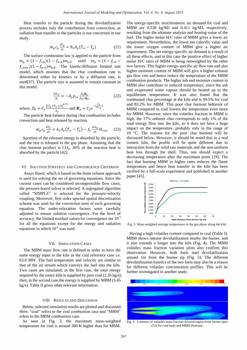
As seen in Fig. 3, the maximum mass-weighted
temperature for coal is around 300 K higher than for MBM.
The energy-specific stoichiometric air demand for coal and
MBM are 0.338 kg/MJ and 0.411 kg/MJ, respectively,
resulting from the ultimate analysis and heating value of the
fuel. The higher molar H/C ratio of MBM gives a lower air
requirement. Nevertheless, the lower net calorific value and
the lower oxygen content of MBM give a higher air
requirement. The net energy-specific air demand is a result of
all these effects, and in this case the positive effect of higher
molar H/C ratio of MBM is being outweighed by the other
two factors. This higher energy-specific air flow rate and also
higher moisture content of MBM will give a higher exhaust
gas flow rate and hence reduce the temperature of the MBM
combustion products. The higher ash and moisture content in
MBM also contribute to reduced temperature, since the ash
and evaporated water vapour should be heated up to the
equilibrium temperature. It was also found that the
combusted char percentage at the kiln end is 99.5% for coal
and 83.2% for MBM. This poor char burnout behavior of
MBM compared to coal lowers the temperature even more
for MBM. However, since the volatiles fraction in MBM is
high, the 17% unburnt char corresponds to only 1% of the
total energy flow into the kiln, so it does not have a huge
impact on the temperature, probably only in the range of
10 °C. The reasons for the poor char burnout will be
discussed below. However, it should be noted that in a real
cement kiln, the profile will be quite different due to
interaction from the solid raw materials and the non-uniform
heat loss through the shell. Thus, one should expect a
decreasing temperature after the maximum point [19]. The
fact that burning MBM in higher rates reduces the flame
temperature and hence heat transfer in the kiln has been
verified by a full-scale experiment and published in another
paper [43].
Fig. 3. Mass-weighted average temperature in the gas phase along the kiln.
Having a high volatiles content compared to coal (Table I),
MBM shows intense devolatilization nearby the burner, and
it also extends a longer into the kiln (Fig. 4). The MBM
volatiles mass fraction variation plots also confirm this
observation. However, both fuels start devolatilization
around 1m from the burner tip (Fig. 5). The different
devolatilization kinetics of the two fuels may also be a reason
for different volatiles concentration profiles. This will be
further investigated in another study.
Fig. 4. Contours of volatiles mass fraction foraxial region from burner tipto
27m for coal (top) and MBM (bottom).
900
1100
1300
1500
1700
1900
2100
2300
2500
2700
0 10 20 30 40 50 60 70
Mas
s w
eigh
ted
aver
age
tem
pera
ture
(K)
Axial distance from burner tip (m)
Coal MBM
267
International Journal of Modeling and Optimization, Vol. 4, No. 4, August 2014
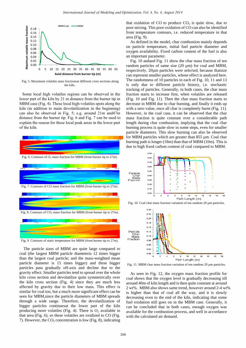
Fig. 5. Maximum volatiles mass fractionsat different cross sections along
the kiln.
Fig. 6. Contours of O2 mass fraction for MBM (from burner tip to 27m).
Fig. 7. Contours of CO mass fraction for MBM (from burner tip to 27m).
Fig. 8. Contours of CO2 mass fraction for MBM (from burner tip to 27m).
Fig. 9. Contours of static temperature for MBM (from burner tip to 27m).
The particle sizes of MBM are quite large compared to
coal (the largest MBM particle diameteris 12 times bigger
than the largest coal particle; and the mass-weighted mean
particle diameter is 15 times bigger) and these bigger
particles pass gradually off-axis and decline due to the
gravity effect. Smaller particles tend to spread over the whole
kiln cross section and devolatilize quite symmetrically over
the kiln cross section (Fig. 4) since they are much less
affected by gravity due to their low mass. This effect is
similar for coal too, but a much more significant effect can be
seen for MBM,since the particle diameters of MBM spreads
through a wide range. Therefore, the devolatilization of
bigger particles continuesat the lower part of the kiln
producing more volatiles (Fig. 4). There is O2 available in
that area (Fig. 6), so these volatiles are oxidized to CO (Fig.
7). However, the CO2 concentration is low (Fig. 8), indicating
that oxidation of CO to produce CO2 is quite slow, due to
poor mixing. This poor oxidation of CO can also be identified
from temperature contours, i.e. reduced temperature in that
area (Fig. 9).
As defined in the model, char combustion mainly depends
on particle temperature, initial fuel particle diameter and
oxygen availability. Fixed carbon content of the fuel is also
an important parameter.
Fig. 10 andand Fig. 11 show the char mass fraction of ten
random particles of same size (20 µm) for coal and MBM,
respectively. 20µm particles were selected, because thatsize
can represent smaller particles, whose effect is analyzed here.
The randomness of 10 particles in each of Fig. 10, 11 and 13
is only due to different particle history, i.e. stochastic
tracking of particles. Generally, in both cases, the char mass
fraction starts to increase first, when volatiles are released
(Fig. 10 and Fig. 11). Then the char mass fraction starts to
decrease in MBM due to char burning, and finally it ends up
with a zero value, once all char is completely burnt (Fig. 11).
However, in the coal case, it can be observed that the char
mass fraction is quite constant over a considerable path
length during char combustion, implying that the coal char
burning process is quite slow in some steps, even for smaller
particle diameters. This slow burning can also be observed
for MBM particles which are greater than 855 µm. Coal char
burning path is longer (18m) than that of MBM (10m). This is
due to high fixed carbon content of coal compared to MBM.
Fig. 10. Coal char mass fraction variation of ten random 20 µm particles.
Fig. 11. MBM char mass fraction variation of ten random 20 µm particles.
As seen in Fig. 12, the oxygen mass fraction profile for
coal shows that the oxygen level is gradually decreasing till
around 40m of kiln length and is then quite constant at around
2 wt%. MBM also shows same trend, however around 2-4 wt%
is higher than that of coal all the way, and it is slowly
decreasing even to the end of the kiln, indicating that some
fuel oxidation still goes on in the MBM case. Generally, it
can be concluded that in both cases, enough oxygen was
available for the combustion process, and well in accordance
with the calculated air demand.
0.000.020.040.060.080.100.120.140.160.18
0 5 10 15 20 25 30 35 40 45 50 55 60 65Max
imu
m v
ola
tile
mas
s fr
acti
on
Axial distance from burner tip (m)
Coal MBM
268
International Journal of Modeling and Optimization, Vol. 4, No. 4, August 2014
Some local high volatiles regions can be observed in the lower part of the kiln by 21 m distance from the burner tip in MBM case (Fig. 4). These local high-volatiles spots along the kiln (in addition to main devolatilization in the beginning) can also be observed in Fig. 5; e.g. around 21m and47m distance from the burner tip. Fig. 6 and Fig. 7 can be used to explain the reason for these local peak areas in the lower part of the kiln.
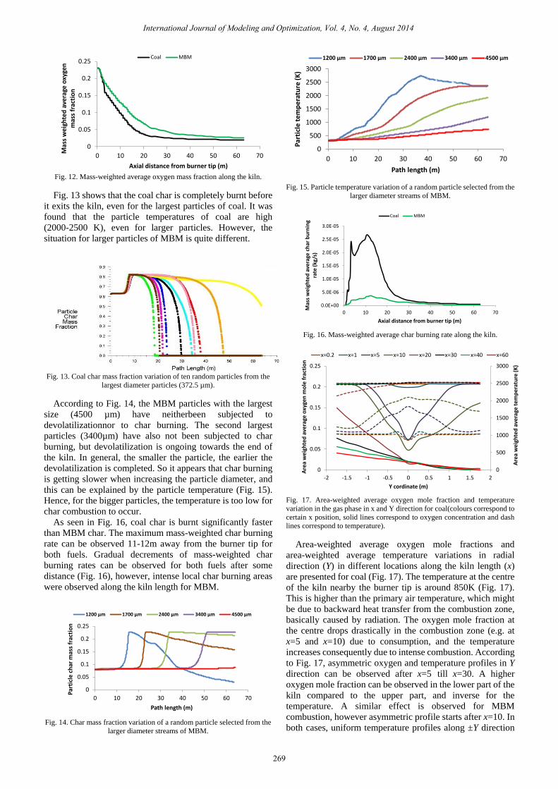
Fig. 12. Mass-weighted average oxygen mass fraction along the kiln.
Fig. 13 shows that the coal char is completely burnt before
it exits the kiln, even for the largest particles of coal. It was
found that the particle temperatures of coal are high
(2000-2500 K), even for larger particles. However, the
situation for larger particles of MBM is quite different.
Fig. 13. Coal char mass fraction variation of ten random particles from the
largest diameter particles (372.5 µm).
According to Fig. 14, the MBM particles with the largest
size (4500 µm) have neitherbeen subjected to
devolatilizationnor to char burning. The second largest
particles (3400µm) have also not been subjected to char
burning, but devolatilization is ongoing towards the end of
the kiln. In general, the smaller the particle, the earlier the
devolatilization is completed. So it appears that char burning
is getting slower when increasing the particle diameter, and
this can be explained by the particle temperature (Fig. 15).
Hence, for the bigger particles, the temperature is too low for
char combustion to occur.
As seen in Fig. 16, coal char is burnt significantly faster
than MBM char. The maximum mass-weighted char burning
rate can be observed 11-12m away from the burner tip for
both fuels. Gradual decrements of mass-weighted char
burning rates can be observed for both fuels after some
distance (Fig. 16), however, intense local char burning areas
were observed along the kiln length for MBM.
Fig. 14. Char mass fraction variation of a random particle selected from the
larger diameter streams of MBM.
Fig. 15. Particle temperature variation of a random particle selected from the
larger diameter streams of MBM.
Fig. 16. Mass-weighted average char burning rate along the kiln.
Fig. 17. Area-weighted average oxygen mole fraction and temperature
variation in the gas phase in x and Y direction for coal(colours correspond to
certain x position, solid lines correspond to oxygen concentration and dash
lines correspond to temperature).
Area-weighted average oxygen mole fractions and
area-weighted average temperature variations in radial
direction (Y) in different locations along the kiln length (x)
are presented for coal (Fig. 17). The temperature at the centre
of the kiln nearby the burner tip is around 850K (Fig. 17).
This is higher than the primary air temperature, which might
be due to backward heat transfer from the combustion zone,
basically caused by radiation. The oxygen mole fraction at
the centre drops drastically in the combustion zone (e.g. at
x=5 and x=10) due to consumption, and the temperature
increases consequently due to intense combustion. According
to Fig. 17, asymmetric oxygen and temperature profiles in Y
direction can be observed after x=5 till x=30. A higher
oxygen mole fraction can be observed in the lower part of the
kiln compared to the upper part, and inverse for the
temperature. A similar effect is observed for MBM
combustion, however asymmetric profile starts after x=10. In
both cases, uniform temperature profiles along ±Y direction
0
0.05
0.1
0.15
0.2
0.25
0 10 20 30 40 50 60 70
Mas
s w
eigh
ted
ave
rage
oxy
gen
m
ass
frac
tio
n
Axial distance from burner tip (m)
Coal MBM
0
0.05
0.1
0.15
0.2
0.25
0 10 20 30 40 50 60 70
Par
ticl
e ch
ar m
ass
frac
tio
n
Path length (m)
1200 µm 1700 µm 2400 µm 3400 µm 4500 µm
0
500
1000
1500
2000
2500
3000
0 10 20 30 40 50 60 70
Par
ticl
e te
mp
erat
ure
(K
)
Path length (m)
1200 µm 1700 µm 2400 µm 3400 µm 4500 µm
0.0E+00
5.0E-06
1.0E-05
1.5E-05
2.0E-05
2.5E-05
3.0E-05
0 10 20 30 40 50 60 70M
ass
wei
ghte
d a
vera
ge c
har
bu
rnin
g ra
te (
kg/s
)
Axial distance from burner tip (m)
Coal MBM
0
500
1000
1500
2000
2500
3000
0
0.05
0.1
0.15
0.2
0.25
-2 -1.5 -1 -0.5 0 0.5 1 1.5 2
Are
a w
eig
hte
d a
vera
ge t
em
pe
ratu
re (
K)
Are
a w
eig
hte
d a
vera
ge o
xyge
n m
ole
fra
ctio
n
Y cordinate (m)
x=0.2 x=1 x=5 x=10 x=20 x=30 x=40 x=60
269
International Journal of Modeling and Optimization, Vol. 4, No. 4, August 2014
can be seen after x=30. The higher oxygen mole fraction in
the lower part of the kiln can be due to; 1) hot combustion
products tend to ascend due to the buoyancy effect and will
then displace cold oxygen in the upper part of the kiln; 2)
bigger fuel particles tend to decline due to the gravity effect,
causing poor burning and hence less consumption of oxygen
and reduced temperature. The higher oxygen mole fractions
of MBM (at x=20 and x=30) at the lower part of the kiln
compared to coal verifies the second effect, because MBM
particles are significantly larger.
IX. CONCLUSION
Meat and bone meal (MBM) combustion and coal
combustion in a rotary cement kiln were simulated and the
results were compared. The equilibrium temperature of the
MBM combustion products is around 300K lower than those
from coal combustion. The lower temperature is mainly due
to thehigher air demand, higher ash and moisture content
andpoor char burnout (83%) of MBM.
Even if enough oxygen is availabile for combustion, local
volatiles-concentrated areas along the kiln could be observed
in the lower part of the kiln for MBM. Most importantly, it
was found that the largest MBM particles (4500 µm) are not
subjected to either devolatilization or char burning and
devolatilization and char burning is getting slower when
increasing the particle diameter of larger particles. The
particle temperature is significantly lower for the larger
MBM particles, explaining the lower char burnout of larger
particles.
In general, for both fuels, a higher oxygen mole fraction
could be observed in the lower part of the kiln. This can be
due to buoyancy effects on the hot gas and gravity effects on
the particles. The impact of the latter is significant in MBM
combustion.
NOMENCLATURE
𝐴 empirical constant, 4.0
𝐴1 Arrhenius type pre-exponential factor, s-1
𝐴𝑝 droplet surface area, m2
𝑎 absorption coefficient, m-1
𝑎1, 𝑎2,𝑎3 constants
𝐵 empirical constant, 0.5
𝐶 linear-anisotropic phase function coefficient
𝐶1 mass diffusion limited rate constant, s K-0.75
𝐶2 kinetics-limited rate pre-exponential
factor,sm-1
C1ε model constant, 1.42
𝐶2ε∗
model constant
𝐶𝑑 drag coefficient
𝐶𝑠𝑤 swelling coefficient
𝑐𝑝 heat capacity at constant pressure, J/kg K
𝐷𝑖,𝑚 mass diffusion coefficient for species i in the
mixture, m2/s
𝐷𝑇,𝑖 thermal (Soret) diffusion coefficient, kg/m s
𝐷0 diffusion rate coefficient, sm-1
𝑑𝑝 current particle diameter, m
𝑑𝑝,0 particle diameter at the start of devolatilization,
m
𝐸 total energy, J/kg
𝐸1 activation energy, J/kmol
𝐹 external body force vector, N/ m3
𝐹𝐷 drag force, s-1
𝑓𝑐𝑜𝑚𝑏
combustible fraction
𝑓 fraction of the heat absorbed by the particle
𝑓𝑣,0
mass fraction of volatiles initially present in the
particle
𝑓𝑤,0
mass fraction of the evaporating/boiling
material
𝐺 incident radiation, W/m2
𝐺𝑏 generation of turbulence kinetic energy due to
buoyancy, J/m3 s
𝐺𝑘 generation of turbulence kinetic energy due to
the mean velocity gradients, J/m3 s
𝑔 gravitational acceleration, m/s2
𝐻𝑟𝑒𝑎𝑐 heat released by the surface reaction, J/kg
enthalpy, J/kg
𝑖 enthalpy of speciesi, J/kg
1 convective heat transfer coefficient, W/m2K
𝐼 unit tensor
𝐽 𝑖 diffusion flux of speciesi, kg/m2s
𝑘 turbulent kinetic energy per unit mass, J/kg
𝑘1, 𝑹𝟏 kinetic rate, s-1 and sm-1
𝑘𝑒𝑓𝑓 effective thermal conductivity, W/m K
𝑀𝑤,𝑖 molecular weight of species i, kg/kmol
𝑚𝑝 current mass of the particle, kg
𝑚𝑝,0 initial mass of the particle, kg
𝑛 refractive index
𝑃 static pressure, Pa
𝑝𝑜𝑥
partial pressure of oxidant species in the gas
surrounding the combusting particle, Pa
𝑞𝑟 radiation heat flux, W/m3
𝑅 gas-law constant, 8.31447 x 10³ J/ kmolK
𝑅𝑒 relative Reynolds number
𝑅𝑖,𝑟 net rate of production of species i due to
reaction r, kg/m3s
𝑅𝑖 net rate of production of species i by chemical
reaction, kg/m3s
𝑆 swirl number
𝑆 heat of chemical reaction and any other
volumetric heat source, W/m3
𝑆𝑖 rate of creation of specie i by addition from the
dispersed phase, kg/ m3 s
𝑆𝑚 mass added to the continuous phase from the
dispersed second phase, kg/m3s
𝑆𝑐𝑡 turbulent Schmidt number
𝑇 temperature, K
𝑇𝑏𝑝 boiling point, K
𝑇𝑝 particle temperature , K
𝑇𝑣𝑎𝑝 vaporization/devolatilizationtemperature, K
𝑇∞ local temperature of the continuous phase, K
𝑡 time, s
𝑢 axial velocity, m/s
𝑢𝑖 velocity magnitude in ith direction, m/s
𝑢 𝑝 particle velocity vector, m/s
𝑢 mean fluid phase velocity, m/s
𝑢 instantaneous value of the fluctuating gas flow
velocity, m/s
𝑣 velocity, m/s
𝑣 overall velocity vector, m/s
270
International Journal of Modeling and Optimization, Vol. 4, No. 4, August 2014
𝑤 tangential velocity, m/s
𝑥𝑖 distance inith direction, m
𝑥 overall distance vector, m
𝑌𝑖 mass fraction of speciesi
𝑌𝑝 mass fraction of a particular product species 𝑝
𝑌𝑹 mass fraction of a particular reactant 𝑹
Greek letters
𝛼𝑘 inverse effective Prandtl number for 𝑘
αε inverse effective Prandtl number for 𝜀
𝜀 turbulent dissipation rate, m2/s3
𝜇 molecular viscosity of the fluid, Pa s
𝜇𝑒𝑓𝑓
effective dynamic viscosity, Pa s
𝜇𝑡 turbulent viscosity, Pa s
ν𝑖,𝑟 stoichiometric coefficients for reactanti in
reaction r
ν𝑗 ,𝑟 stoichiometric coefficients for productj in
reaction r
𝜌 density of continuous phase, kg/m3
𝜌𝑝 density of the particle , kg/m3
𝜎 Stefan-Boltzmann constant, 5.67 × 10⁻⁸ W/m2
K4
𝜎𝑠 scattering coefficient, m-1
𝜏 stress tensor , Pa
𝜏 𝑒𝑓𝑓 effective stress tensor, Pa
Γ parameter in radiation
REFERENCES
[1] Z. Demján, The Possible Impact of CO2 Trading on Competitiveness of
Cement Industry, Slovak Cement & Lime Association, 2005.
[2] A. Rahman, M. G. Rasul, M. M. K. Khan, and S. Sharma, "Impact of
Alternative Fuels on the Cement Manufacturing Plant Performance:
An Overview," Procedia Engineering, vol. 56, pp. 393-400, 2013.
[3] H. A. Spang, "A dynamic model of a cement kiln," Automatica, vol. 8,
pp. 309-323, 1972.
[4] H. K. Guruz, and N. Bac, "Mathematical modelling of rotary cement
kilns by the zone method," The Canadian Journal of Chemical
Engineering, vol. 59, no. 4, pp. 540-548, 1981.
[5] T. Avgeropoulos, J. P. Glekas, and C. Papadopoulos, "Numerical
simulation of the combustion aerodynamics inside a rotary cement
kiln," Energy Efficiency in Process Technology, Pilavachi PA:
Springer Netherlands, 1993, pp. 767-778.
[6] F. C. Lockwood and B. Shen, "Performance predictions of
pulverised-coal flames of power station furnace and cement kiln
types," in Proc. Symposium (International) on Combustion, vol. 25, no.
1, pp. 503-509, 1994.
[7] F. C. Lockwood, B. Shen, and T. Lowes, "Numerical study of
petroleum coke fired cement kiln flames," presented at the third
International Conference on Combustion Technologies for a Clean
Environment, Lisbon, Portugal July 3-6, 1995.
[8] E. Kolyfetis, and N. C. Markatos, "Aerodynamics and coal- Flame
modelling in the burning zone of cement rotary kilns, part 1," ZKG
international, vol. 49, no. 1, pp. 24-35, 1996.
[9] E. Kolyfetis and N. C. Markatos, "Aerodynamics and coal- Flame
modelling in the burning zone of cement rotary kilns, part 2," ZKG
international, vol. 49, no. 6, pp. 326-334, 1996.
[10] N. C. Markatos, "Mathematical modelling of single- and two-phase
flow problems in the process industries," Revue de l’institut franais du
petrole, vol. 48, no. 6, pp. 631-662, 1998.
[11] K. C. Karki, S. V. Patankar, and J. Grant, "Simulation of Fluid Flow,
Combustion, and Heat Transfer in a Coal-Fired Cement Kiln,"
presented at the Combustion, Fire, and Computational Modeling of
Industrial Combustion Systems, 2000.
[12] S. V. Patankar, "Computational modeling of flow and heat transfer in
industrial applications," International Journal of Heat and Fluid Flow,
vol. 23, no. 3, pp. 222-231, 2002.
[13] E. Mastorakos et al., "CFD predictions for cement kilns including
flame modelling, heat transfer and clinker chemistry," Applied
Mathematical Modelling, vol. 23, no. 1, pp. 55-76, 1999.
[14] O. Marin, O. Charon, J. Dugue, S. Dukhan, and W. E. I. Zhou,
"Simulating the impact of oxygen enrichment in a cement rotary kiln
using advanced computational methods," Combustion Science and
Technology, vol. 164, no. 1, pp. 193-207, 2001.
[15] L. Y. Hou, W. B. Fu, and Y. J. Zhang, "A theoretical analysis on
combustion intensification for blended coal in rotary cement kiln,"
Fuel, vol. 80, no. 11, pp. 1645-1650, 2001.
[16] M. Georgallis, P. Nowak, M. Salcudean, and I. S. Gartshore,
"Mathematical modelling of lime kilns," presented at the International
Chemical Recovery Conference, 2001.
[17] G. Locher, "Mathematical models for the cement clinker burning
process-Part 3: Rotary kiln," ZKG international, vol. 55, no. 2, pp.
68-80, 2002.
[18] T. Ginsberg, D. Liebig, M. Modigell, K. Hack, and S. Yousif,
"Simulation of a cement plant using thermochemical and flow
simulation tools," presented at the European Symposium on Computer
Aided Process Engineering- 15, 2005.
[19] S. Wang, J. Lu, W. Li, J. Li, and Z. Hu, "Modelling of pulverised coal
combustion in cement rotary kiln," Energy & Fuels, vol. 20, pp.
2350-2356, 2006.
[20] K. S. Mujumdar, A. Arora, and V. V. Ranade, "Modeling of Rotary
Cement Kilns: Applications to Reduction in Energy Consumption,"
Industrial & Engineering Chemistry Research, vol. 45, no. 7, pp.
2315-2330, 2006.
[21] K. S. Mujumdar and V. V. Ranade, "Simulation of Rotary Cement
Kilns Using a One-Dimensional Model," Chemical Engineering
Research and Design, vol. 84, no. 3, pp. 165-177, 2006.
[22] K. S. Mujumdar and V. V. Ranade, "CFD modeling of rotary cement
kilns," Asia-Pacific Journal of Chemical Engineering, vol. 3, no. 2, pp.
106-118, 2008.
[23] K. S. Mujumdar, K. V. Ganesh, S. B. Kulkarni, and V. V. Ranade,
"Rotary Cement Kiln Simulator (RoCKS): Integrated modeling of
pre-heater, calciner, kiln and clinker cooler," Chemical Engineering
Science, vol. 62, no. 9, pp. 2590-2607, 2007.
[24] A.-C. Ma, J.-M. Zhou, J.-P. Ou, and W.-X. Li, "CFD prediction of
physical field for multi-air channel pulverized coal burner in rotary
kiln," Journal of Central South University of Technology, vol. 13, no. 1,
pp. 75-79, 2006.
[25] S. Suhail, T. Abbas, and F. C. Lockwood, "Advanced Computational
Tools for Cement Plants." Cement Industry Technical Conference
Record, 2008 IEEE, 18-22 May 2008, 2008.
[26] T. P. Bhad, S. Sarkar, A. Kaushik, and S. V. Herwadkar, "CFD
modelling of a cement kiln with multi channel burner for optimization
of flame profile," presented at the seventh International Conference on
CFD in the Minerals and Process Industries, Australia, pp. 9-11, 2009.
[27] H. Mikulčić et al., "Numerical modelling of calcination reaction
mechanism for cement production," Chemical Engineering Science,
vol. 69, no. 1, pp. 607-615, 2012.
[28] M. Modigell, D. Liebig, and S. Munstermann, "Calculation of the
clinker burning process using thermochemical process simulation,"
ZKG international, vol. 55, no. 7, pp. 38-46, 2002.
[29] U. Kääntee, R. Zevenhoven, R. Backman, and M. Hupa, "Cement
manufacturing using alternative fuels and the advantages of process
modelling," Fuel Processing Technology, vol. 85, no. 4, pp. 293-301,
2004.
[30] S. L. Douglas, "Pulverized coal diffusion flames: A perspective
through modeling," Presented at the Symposium (International) on
Combustion, 1981.
[31] S. L. Douglas, "Modeling of coal-combustion processes," Progress in
Energy and Combustion Science, vol. 10, no. 2, pp. 229-267, 1984.
[32] G. Nathan and B. B. Dally, "Challenges and progress in the modelling
of heat transfer and NOx emissions from rotary kiln flames involving
unsteady flows," Presented at the Third International Conference on
CFD in the Minerals and Process Industries, 2003.
[33] O. P. Mahajan and P. L. Walker, "Porosity of coals and coal products,"
in Analytical methods for coal and coal products 1, USA: Acedamic
Press.Inc, 1978, pp. 125-162.
[34] R. A. Garcia, K. A. Rosentrater, and R. A. Flores, "Characteristics of
North American meat and bone meal relevant to the development of
non-feed applications," Applied Engineering in Agriculture, vol. 22, no.
5, pp. 729-736, 2006.
[35] S. Badzioch and P. G. W. Hawksley, "Kinetics of Thermal
Decomposition of Pulverized Coal Particles," Industrial &
Engineering Chemistry Process Design and Development, vol. 9, no. 4,
pp. 521-530, 1970.
271
International Journal of Modeling and Optimization, Vol. 4, No. 4, August 2014
[36] G. Skodras et al., "A kinetic study on the devolatilisation of animal
derived byproducts," Fuel Processing Technology, vol. 88, pp.
787-794, 2007.
[37] Fluent, "Discrete Phase," in ANSYS FLUENT Theory Guide, 13.0 ed,
USA: Ansys Inc, 2010, pp. 367-454.
[38] S. C. Saxena, "Devolatilization and combustion characteristics of coal
particles," Progress in Energy and Combustion Science, vol. 16, no. 1,
pp. 55-94, 1990.
[39] A. A. F. Peters and R. Weber, "Mathematical modeling of a 2.25 MWt
swirling natural gas flame. Part 1: eddy break-up concept for turbulent
combustion; probability density function approach for nitric oxide
formation," Combustion Science and Technology, vol. 110, pp. 67-101,
1995.
[40] B. F. Magnussen and B. H. Hjertager, "On mathematical modeling of
turbulent combustion with special emphasis on soot formation and
combustion," Symposium (International) on Combustion, vol. 16, no. 1,
pp. 719-729, 1977.
[41] S. A. Morsi and A. J. Alexander, "An investigation of particle
trajectories in two-phase flow systems," J Fluid Mech, vol. 55, no. 2,
pp. 193-208, 1972.
[42] R. K. Boyd, and J. H. Kent, "Three-dimensional furnace computer
modelling," Symposium (International) on Combustion, vol. 21, no. 1,
pp. 265-274, 1988.
[43] W. K. H. Ariyaratne, M. C. Melaaen, K. Eine, and L. A. Tokheim,
"Meat and bone meal as a renewable energy source in cement kilns:
Investigation of optimum feeding rate," Presented at the International
Conference on Renewable Energies and Power Quality, Las Palmas de
Gran Canaria (Spain), 13-15 April, 2010.
W. K. Hiromi Ariyaratne has one MSc degree in
process technology (Telemark University College
(TUC), Porsgrunn, Norway, 2009) and another MSc
degree in chemical and process engineering
(University of Moratuwa (UOM), Moratuwa, Sri
Lanka, 2007) and a BSc degree in chemical and
process engineering (UOM, 2004).
She is a PhD student at TUC since 2009, where her
topic is related to alternative fuel combustion in
cement kilns. She has worked on research projects as a
research fellow in Sevanagala Sugar Industries (Pvt) Ltd, Sri Lanka and
Research and Development Institute, Sri Lanka (2006-2007). She has work
experience as a chemical and process engineer in Hammer International (Pvt)
Ltd, Sri Lanka (2006) and Linea Intimo (Pvt) Ltd, Sri Lanka (2003). She has
also worked at the Department of Chemical and Process Engineering at
UOM as Teaching Assistant (2005).
Mrs. Ariyaratne’s research interests are alternative fuel combustion in
cement clinker production, modeling and simulation, fluid dynamics, heat
and mass transfer and cleaner production and waste management techniques.
Anjana Malagalage has a BSc degree in chemical
and process engineering (University of Moratuwa
(UoM), Moratuwa, Sri Lanka, 2010)
He is an MSc student in process technology at
Telemark University College (TUC), Norway since
2012. He has worked at the Department of Chemical
and Process Engineering at UoM as a lecturer
(probationary) (2010-2012). He has also worked as a
summer student at TUC on a research project carried
out with StatOil (2013).
Mr. Anjana’s research interests are modeling and simulation, fluid
mechanics and heat and mass transfer.
Morten C. Melaaen received his MSc degree in
mechanical engineering in 1986 and his PhD in 1990,
both from Norwegian University of Science and
Technology (NTNU), Trondheim, Norway.
He is a professor in process technology at Telemark
University College, Porsgrunn, Norway. He is also the
dean of Faculty of Technology, Telemark University
College and has a part time position at the local
research institute Tel-Tek. Earlier, he has worked as a
research engineer in Division of Applied
Thermodynamics, SINTEF, Norway and as an associate professor at NTNU.
He has worked on research projects as a senior research scientist in Norsk
Hydro Research Centre Porsgrunn, Norway. He started to work as a
professor at Telemark University College in 1994 and became the head of
Department, Department of Process, Energy and Environmental Technology
in 2002.
Prof. Melaaen’s research interests are CO2 capture, modeling and
simulation, fluid mechanics and heat and mass transfer. Prof. Melaaen has
more than 110 scientific papers published in the above mentioned related
fields in international journals and conferences.
Lars-André Tokheim has a PhD degree in
combustion (Telemark University College (TUC),
Porsgrunn, Norway, 1999), an MSc degree in
industrial environmental technology (TUC, 1994) and
a BSc degree in chemistry (TUC, 1992).
He is an associate professor at TUC since 2006,
where he teaches gas purification and heat & mass
transfer, supervises MSc and PhD students, and
coordinates master study programmes in process
technology and energy & environmental technology as
well as a PhD study programme in process, energy and automation
engineering. He has industrial experience from Norcem/Heidelberg Cement
since 1994: as a research scholar (1994-1998), as a process engineer in the
production department (1998-2001), and as the head of Department for
Process Development and Environment (2001-2006).
Prof. Tokheim’s main research interests include use of alternative fuels in
cement clinker production, calciner technology and gas pollution reduction,
in particular CO2 capture and NOx reduction.
Author’s formal
photo
Author’s formal
photo
Author’s formal
photo
Author’s formal
photo
272
International Journal of Modeling and Optimization, Vol. 4, No. 4, August 2014