Embed Size (px)
Citation preview

CFD MODELING FOR HIGH RATE PULVERIZED COAL INJECTION (PCI)
IN THE BLAST FURNACE
Overview of Project Progress
Chenn Q. ZhouProfessor of Mechanical Engineering
Purdue University CalumetHammond, IN 46321

PROJECT OVERVIEWParticipants:
ArcelorMittal USA-Indiana Harbor DofascoStelco Inc.US SteelUnion gas Purdue University Calumet
Duration: 24 +7 MonthsStart Date: May 2005Funding Agent: AISI/DOE and Indiana 21st Century Research and Technology Fund

PROJECT GOALS
To help the steel industry in using advanced technology for optimizing the PCI process to
increase PCI rate improve fuel efficiencysave energyreduce pollutant emission
To lay a solid foundation for developing a comprehensive model for the whole blast furnace to optimize the operationTo enhance education program at PUC
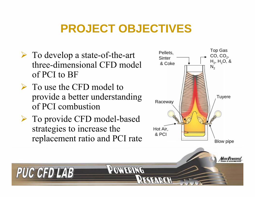
PROJECT OBJECTIVES
To develop a state-of-the-art three-dimensional CFD model of PCI to BF To use the CFD model to provide a better understanding of PCI combustionTo provide CFD model-based strategies to increase the replacement ratio and PCI rate
Top GasCO, CO2, H2, H2O, & N2
Hot Air, & PCI
RacewayTuyere
Pellets, Sinter& Coke
Blow pipe
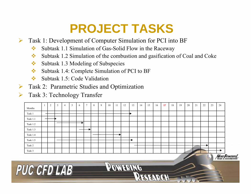
PROJECT TASKSTask 1: Development of Computer Simulation for PCI into BF
Subtask 1.1 Simulation of Gas-Solid Flow in the RacewaySubtask 1.2 Simulation of the combustion and gasification of Coal and Coke Subtask 1.3 Modeling of Subspecies Subtask 1.4: Complete Simulation of PCI to BF Subtask 1.5: Code Validation
Task 2: Parametric Studies and Optimization Task 3: Technology Transfer
Task 3
Task 2
Task 1.5
Task 1.4
Task 1.3
Task 1.2
Task 1.1
Task 1
242322212019181716151413121110987654321Months
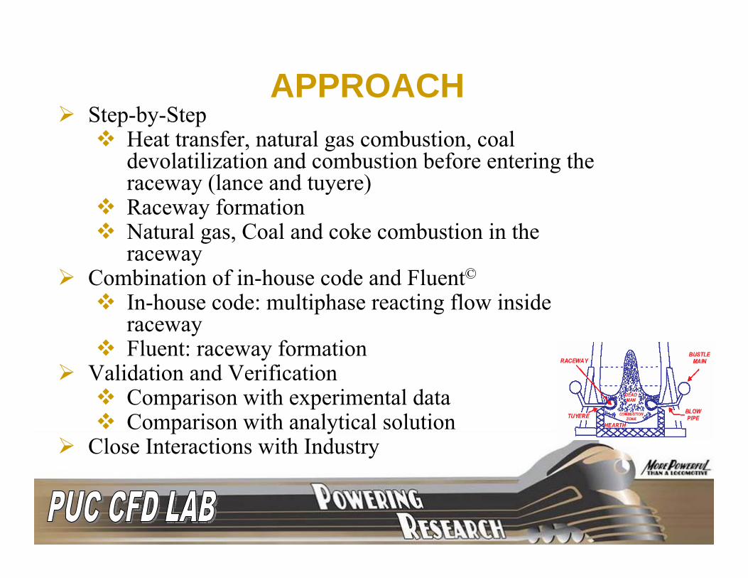
APPROACHStep-by-Step
Heat transfer, natural gas combustion, coal devolatilization and combustion before entering the raceway (lance and tuyere)Raceway formationNatural gas, Coal and coke combustion in the raceway
Combination of in-house code and Fluent©
In-house code: multiphase reacting flow inside racewayFluent: raceway formation
Validation and VerificationComparison with experimental dataComparison with analytical solution
Close Interactions with Industry

SUMMARY OF ACCOMPLISHMENTS
Developed multiphase PCI CFD Models and In-House codeValidated the multiphase PCI CFD Models and In-House codeSimulated different furnaces for ArcelorMittal, Dofasco, Stelco, and USS casesConducted parametric studies

PART I
LANCE AND TUYERE

LANCE AND TUYEREFluent is used
3-dimensional, TurbulentHeat transferMultiphase flowMultispecies reactionsCoal combustionNatural gas co-injection
Cases studied for ArcelorMittal: Coal devolatization in the lance; Effects of PCI rate, PCI carrier gas flow rate, Oxygen lance flow rate, and blast air temperature, etc.StelcoDofasco
STELCO CASES
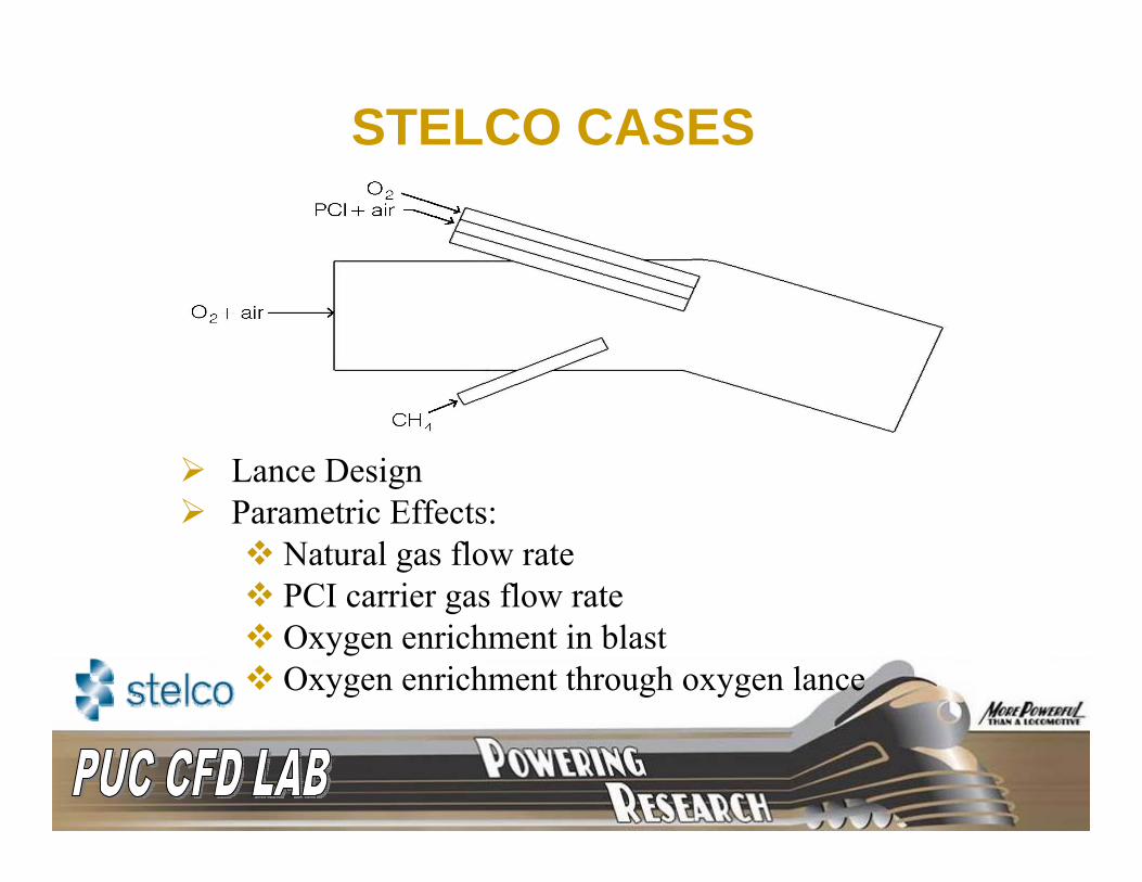
Lance DesignParametric Effects:
Natural gas flow ratePCI carrier gas flow rateOxygen enrichment in blastOxygen enrichment through oxygen lance

0.30760.30760.28640.2970.30760.3076Oxygen mass fraction in blast
0.0570.0570.0570.0570.0460.057PCI carrier gas rate (kg/s)
0.03670.04280.07330.0520.01170.0117Mass fraction steam in blast
137212551372137213721372Blast temperature (K)
0.1800.1440.1140.1460.1800.180NG rate (kg/s)
0.3080.3080.3080.3080.3080.308PCI rate (kg/s)
0.07110.10670.10670.10670.10670.1067Lance oxygen rate (kg/s)
3.123.123.123.123.123.12Wind rate
(kg/s)
case5case4case3case2case1base caseParameter
SIMULATION CONDITIONS

RESULTS OF BASE CASE
Mass Fraction CH4 Temperature (K)
Devolatilization Rate (kg/s)

0.050
0.055
0.060
0.065
0.070
0.0711 0.107Oxygen Flow Rate Through Lance (kg/s)
Tota
l Dev
olat
iliza
tion
(kg
EFFECTS OF CARRIER AIR RATEAND OXGEN FLOW RATE
0.050
0.054
0.058
0.062
0.066
0.058 0.046Carrier Air Flow Rate (kg/s)
Tota
l Dev
olat
iliza
tion
(kg
As carrier air mass flow rate is increased, devolatilization rate decreases due to less residence time before entering raceway. As oxygen lance flow rate is increased, devolatilization rate decreases due to oxygen cooling and decreased residence time.
Basecase
Case 1 Case 5
Basecase

EFFECTS OF N.G. FLOWRATE
As natural gas flow rate is increased, devolatilization rate increases due to higher temperatures.As natural gas flow rate is increased, oxygen lance temperature increases.
0.0480.0500.0520.0540.0560.0580.0600.062
0.18 0.15 0.12Methane flow rate (kg/s)
Tota
l Dev
olat
iliza
tion
(kg
Case 2
Case 3
Basecase
1495
1500
1505
1510
1515
1520
0.181 0.147 0.115Methane flow rate (kg/s)
Max
. Lan
ce T
empe
ratu
re
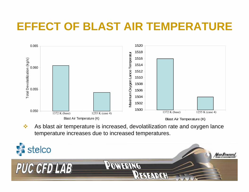
EFFECT OF BLAST AIR TEMPERATURE
0.050
0.055
0.060
0.065
Blast Air Temperature (K)
Tota
l Dev
olat
ilizat
ion
(kg/
s)
1372 K (base) 1255 K (case 4)1500
1502
1504
1506
1508
1510
1512
1514
1516
1518
1520
Blast Air Temperature (K)
Max
imum
Oxy
gen
Lanc
e Te
mpe
ratu
r
1372 K (base) 1255 K (case 4)
As blast air temperature is increased, devolatilization rate and oxygen lance temperature increases due to increased temperatures.

DOFASCO CASESEFFECT OF PRESSURE
Contours of Temperature (K) Contours of Devolatilizaiton (kg/s)
P = 5.813 atm
P = 3.313atm

EFFECT OF PRESSURE
0
500
1000
1500
2000
2500
3000
0 0.1 0.2 0.3 0.4 0.5
Distance from Lance Tip (m)
Tem
pera
ture
(K)
Base CaseP = 5.813 atm
0.00E+00
2.00E-05
4.00E-05
6.00E-05
8.00E-05
1.00E-04
1.20E-04
1.40E-04
0 0.1 0.2 0.3 0.4 0.5
Distance from Lance Tip (m)
Dev
olat
iliza
tion
(kg/
s)
Base CaseP = 5.813 atm
0
0.01
0.02
0.03
0.04
0.05
0.06
Base 5.813 atm
Tota
l Dev
olat
iliza
tion
(kg/
s)
Temperature vs. Distance from Lance Devolatilization vs. Distance from Lance
Total Devolatilization in the Tuyere
As blast pressure is increased, devolatilization rate and residence time increase.

PART II
RACEWAY FORMATION

RACEWAY FORMATION KINETICSFluent is used
3-D transient gas-particle flow simulationsEulerian approachA multi-fluid granular model is used to describe the flow behavior of the fluid-solid mixture.
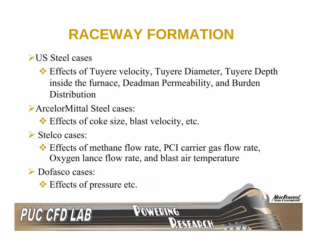
RACEWAY FORMATIONUS Steel cases
Effects of Tuyere velocity, Tuyere Diameter, Tuyere Depth inside the furnace, Deadman Permeability, and Burden Distribution
ArcelorMittal Steel cases:Effects of coke size, blast velocity, etc.
Stelco cases: Effects of methane flow rate, PCI carrier gas flow rate, Oxygen lance flow rate, and blast air temperature
Dofasco cases:Effects of pressure etc.

RACEWAY FORMATION
Measured Raceway as per Hiroshi Nogami et al
CFD
Validation and Verification
“Raceway design for the Innovative Blast Furnace”, Hiroshi Nogami, Hideyki Yamaoka, Kouji Takayani, ISIJ 2004.

VALIDATION“ Prediction of Raceway size in Blast Furnace from 2D experimental correlations”, S Rajneesh, S Sarkar and G.S Gupta, ISIJ international, Vol 44(2004)Empherical equations used:
0.82 20.25164 g b T
r w Teff p
v DD D
gd HWρ
μρ
−⎛ ⎞
= ⎜ ⎟⎜ ⎟⎝ ⎠
1.2
1.4
1.6
1.8
2
2.2
170 180 190 200 210 220
Velocity, m/s
Rac
eway
Dep
th, m
ExperimentalCFD
1
1.2
1.4
1.6
1.8
2
2.2
0.35 0.45 0.55 0.65
Initial Porosity
ExperimentalCFD
1.1
1.3
1.5
1.7
1.9
2.1
0.02 0.025 0.03 0.035 0.04
Coke Diameter, m
Experimental
CFD

RACEWAY FORMATION DYNAMICSARCELORMITTAL AND USS
3 tuyeres located 9°apart, with a diameter of 0.15m at a downward angle of 6°Parametric Effects: Tuyere velocity, Tuyere Diameter, Tuyere Depth inside the furnace, Deadman Permeability, and Burden Distribution

EFFECT OF BLAST VELOCITY
Raceway is defined as the boundary where the coke volume fraction is equal to the initial porosity near the tuyereV , Raceway size

EFFECT OF TUYERE SIZE
Length , Raceway depth Diameter , Raceway size

EFFECT OF DEADMAN POROSITY AND COKE PARTICLE SIZE
Porosity , Raceway depth Particle size , Raceway size

EFFECT OF BURDEN DISTRIBUTION

DOFASCO CASES
Dimensions are based on BF#4 of Dofasco

PART III
RACEWAY COMBUSTION

Main Features of In-House PCI CFD Code3-dimensionalTurbulentMultiphase flow (gas, pulverized coal, and coke particles)Heat transferMultispecies reactionsCoke combustionCoal combustion Natural gas co-injection
RACEWAY COMBUSTION

CFD ModelEulerian approach
k-ε Turbulence modelCoal moisture evaporation rateCoal devolatilization rateChar combustion rateCoke combustion rateNatural gas combustion rate
RACEWAY COMBUSTION
Pgφφφφφ )()()()()()( SSz
Γzy
Γyx
Γx
wz
vy
ux
++∂∂
∂∂
+∂∂
∂∂
+∂∂
∂∂
=∂∂
+∂∂
+∂∂ φφφφρφρφρ
PgφPφP
φPP
φPP
φPPPPPPPPPP )()()()()()( SSz
Γzy
Γyx
Γx
wz
vy
ux
++∂∂
∂∂
+∂∂
∂∂
+∂∂
∂∂
=∂∂
+∂∂
+∂∂ φφφ
φρφρφρ

RACEWAY COMBUSTIONValidation
00.10.20.30.40.50.60.70.8
0 0.1 0.2 0.3 0.4 0.5 0.6
Distance from the tuyere nose (m)
Mas
s fr
actio
n (-)
N2
CO
O2
CO2
Data from: H. Nogami et al: ISIJ 2004, No.12: 2150

RACEWAY COMBUSTIONValidation
Φ8
Φ12
Φ18 Φ30
Φ34
coal +carrying air primary air secondary air
reactor tube (Ф200mm)
burner
0
5
10
15
20
25
0 0.3 0.6 0.9 1.2 1.5
Distance from burner [m]
O2
[vol
%] Experimental
Predicted
0
4
8
12
16
20
0 0.3 0.6 0.9 1.2 1.5
Distance from burner [m]
CO
2 [v
ol %
]
Experimental
PredictedExperimental Setup (Zhang Y. Wei X L, Zhou L X, Sheng H Z. Simulation of coal combustion by AUSM turbulence –chemistry char combustion model and a full two-fluid mode. Fuel 2005; 84: 1798-1804)

RACEWAY COMBUSTION CASESStelco cases:
Coke, coal, and natural gas combustionEffects of methane flow rate, PCI carrier gas flow rate, Oxygen lance flow rate, and blast air temperature
ArcelorMittal USA cases:Coke combustion onlyEffects of coke size, blast velocity, etc.
Dofasco cases:Coke combustion onlyEffects of pressure etc.

METHODOLOGY OF SIMULATION
Tuyeres
Dripping Zone
Chimney
Coke Bed
Dead man
Liquid level
Cohesive Zones
NG lance
Coal lance
Blowpipe
Tuyere
Oxygen pipe
(a) Simulation of NG+coal inside a tuyere
(b) Obtain the raceway shape and size
(c) Schematic of Race way combustion

0.30760.30760.28640.2970.30760.3076Oxygen mass fraction in
blast
0.0570.0570.0570.0570.0460.057PCI carrier rate (kg/s)
0.03670.04280.07330.0520.01170.0117Mass fraction steam in
blast
137212551372137213721372Blast temperature (K)
0.1800.1440.1140.1460.1800.180NG rate (kg/s)
0.3080.3080.3080.3080.3080.308PCI rate (kg/s)
0.07110.10670.10670.10670.10670.1067Lance oxygen
rate (kg/s)
3.123.123.123.123.123.12Wind rate (kg/s)
case5case4case3case2case1base caseParameter
SIMULATION CONDITIONS AND CASES

INLET CONDITIONS FOR RACEWAY COMBUSTION –base case
Tg Pressure Mean molecular weight
X- velocity Y-velocity Z- velocity

GAS TEMPERATURE AND GAS SPECIES (base case)
Tg
CH4 O2
CO2

EFFECT OF CARRIER AIR RATE
0
0.2
0.4
0.6
N2 0.512715148 0.515384959
co 0.472829876 0.470091232
H2 0.014454976 0.01452381
cokeconsumption(kg/s)
0.467 0.46
base case1
base
case1

0.150.200.250.300.350.400.450.500.550.60
base case2 case3
Mas
s fra
ctio
n
0.012
0.0130.014
0.0150.016
0.017
0.0180.019
0.020
H2
mas
s fra
ctio
n
N2cocoke consumption(kg/s)H2
EFFECT OF NATURAL GASFLOW RATE
Coke consumption rate increases with the decreasing of the NG flow rate;CO and H2 increases with the decreasing of the NG flow rate
0
0.1
0.2
0.3
0.4
0.5
0.6
base case5
Coke consumption rate, kg/sCOH2N2
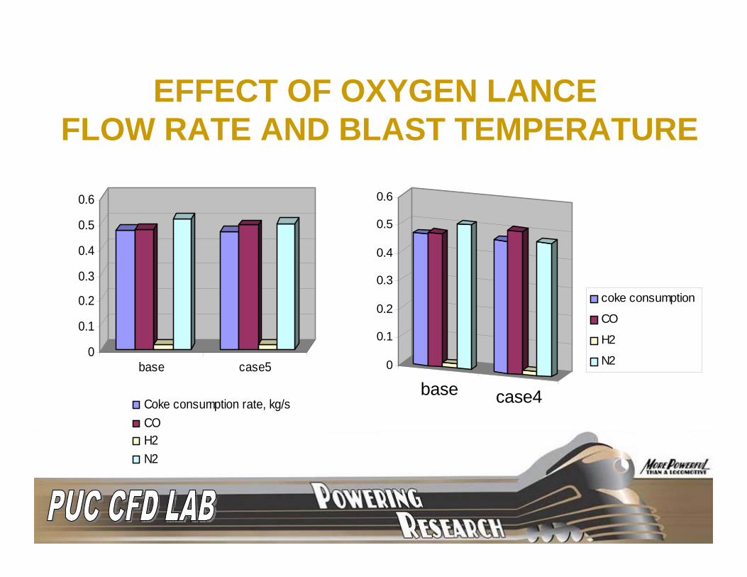
EFFECT OF OXYGEN LANCE FLOW RATE AND BLAST TEMPERATURE
base case4
0
0.1
0.2
0.3
0.4
0.5
0.6
coke consumption
CO
H2
N2

OUTLET GAS TEMPERATURE
1800
1850
1900
1950
2000
base case1 case2 case3 case4 case5
cases
Tg, K

DOFOSCO CASESP= 3.313 atm P= 5.813 atm

BASE CASE RESULTS
1400
1700
2000
2300
2600
0.0 0.5 1.0 1.5 2.0 2.5
Tem
pera
ture
(K)
0.00
0.10
0.20
0.30
0.40
Mas
s Fr
actio
ns
Tg
O2
Co
CO2
Distance from tuyere inlet central point
ARCELORMITTAL CASES

BASE CASE RESULTS
tg
CO O2
CO2Tg

EFFECT OF BLAST INLET VELOCITY
Vb=156 Nm/s Vb=170 Nm/s Vb=184 Nm/s

EFFECT OF COKE SIZE
Dp=0.04m Dp=0.03m
X [m]

SUMMARYDeveloped and validated the multiphase PCI CFD Models and In-House code
heat transfer, devolatilization and combustion of injected coal before entering racewaysRaceway formationCoal and coke combustion in the racewayNatural gas and coal co-injection
Conducted parametric studies for ArcelorMittal, Dofasco, Stelco, and USS casesResults have been used for understanding and improving PCI process More parametric studies are on-going

AISI/DOE Indiana 21st Century Research and Technology FundIndustrial CollaboratorsPurdue Calumet Research Team Members
ACKNOWLEDGEMENT