Embed Size (px)
Citation preview
8/10/2019 CFD Missile Fuel Venting and Plume AIAA-2007-1012.pdf
http://slidepdf.com/reader/full/cfd-missile-fuel-venting-and-plume-aiaa-2007-1012pdf 1/13
AIAA-2007-1012
Progress in Modeling Missile Fuel Venting and Plume
Contrail Formation
J.D. Chenoweth*, K.W. Brinckman
†, B.J. York
‡, G. Feldman
§, and S.M. Dash
**
Combustion Research & Flow Technology, Inc. (CRAFT Tech) Huntsville, AL, Pipersville, PA and Charlotte, NC
Email: [email protected]
ABSTRACT
In this paper, we discuss progress made in extending specialized missile plume codes to
analyze more generalized problems entailing varied missile propulsive flowfield phenomena.
Problems of interest include those of fuel venting and plume contrail formation. To analyze
such processes, gas/liquid modeling is being incorporated that includes primary and
secondary breakup, and vaporization/condensation physics. This is being performed at an
engineering level and overall progress in extending plume codes to analyze these processeswill be described. Exemplary problems described include those of both gaseous and liquid
fuel venting, application of unified secondary breakup and vaporization of a liquid fuel
venting problem, and, contrail formation in a generic missile plume.
I. Introduction
here are a number of plume/propulsive related problems of great interest to the missile community that are not
presently analyzable with engineering-oriented plume codes. These problems include the modeling of eventssuch as fuel venting (occurring during staging or in other scenarios), and, the formation of contrails produced by
water condensation (secondary smoke formation) in the plume. The modeling of such events requires the inclusion
of gas/liquid methodology into the plume codes, performed at an engineering level to keep the codes fast runningand easy to use. The gas/liquid methodology being incorporated is summarized in Table I. This paper will
summarize progress made in extending plume codes to analyze varied propulsive related events, focusing on aspectsof the gas/liquid methodology being incorporated.
T
II. Missile Plume Code Features
The principal features of new, engineering-oriented missile plume codes developed by CRAFT Tech are
summarized in Table II, with many of the plume specific features having evolved from recent Navier-Stokes code
development focused on inclusion of advanced particle methodology P1, turbulence modeling 2, and turbulent
combustion 3. These codes have been configured to provide rapid solutions of the complete missile/plume flowfieldin a user-friendly manner employing a GUI driven menu. The zonal methodology used is shown in Figure 1 and
described in Table III.
The continuum plume codes use a combination of PNS and RANS numerics, implementing RANS methodologywith adaptive grids to analyze the base region of plumes and plume-induced separation. They contain turbulent
combustion methodology to analyze plumes under conditions where afterburning is marginal. CRAFT Tech has
three on-going experimental programs to obtain high-fidelity base-region data, plume-induced separation data, and
data in the marginal afterburning regime. These programs are supported by the Army, NASA and MDA and are
being performed in collaboration with Calspan University of Buffalo (LENS shock tunnel data – Holden, et al.) and
* Research Scientist, Huntsville, AL, Member AIAA † Research Scientist, Pipersville, PA, Member AIAA ‡ Principal Research Scientist, Pipersville, PA Member AIAA
§ Research Scientist, Charlotte, NC, Member AIAA ** President & Chief Scientist, Pipersville, PA Associate Fellow AIAA.
1American Institute of Aeronautics and Astronautics
8/10/2019 CFD Missile Fuel Venting and Plume AIAA-2007-1012.pdf
http://slidepdf.com/reader/full/cfd-missile-fuel-venting-and-plume-aiaa-2007-1012pdf 2/13
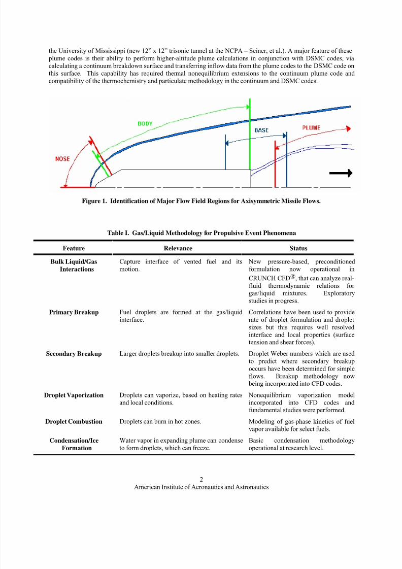
the University of Mississippi (new 12” x 12” trisonic tunnel at the NCPA – Seiner, et al.). A major feature of these
plume codes is their ability to perform higher-altitude plume calculations in conjunction with DSMC codes, via
calculating a continuum breakdown surface and transferring inflow data from the plume codes to the DSMC code on
this surface. This capability has required thermal nonequilibrium extensions to the continuum plume code and
compatibility of the thermochemistry and particulate methodology in the continuum and DSMC codes.
Figure 1. Identification of Major Flow Field Regions for Axisymmetric Missile Flows.
Table I. Gas/Liquid Methodology for Propulsive Event Phenomena
Feature Relevance Status
Bulk Liquid/Gas
Interactions
Capture interface of vented fuel and its
motion.
New pressure-based, preconditioned
formulation now operational in
CRUNCH CFD®, that can analyze real-
fluid thermodynamic relations forgas/liquid mixtures. Exploratory
studies in progress.
Primary Breakup Fuel droplets are formed at the gas/liquid
interface.
Correlations have been used to provide
rate of droplet formulation and droplet
sizes but this requires well resolved
interface and local properties (surfacetension and shear forces).
Secondary Breakup Larger droplets breakup into smaller droplets. Droplet Weber numbers which are used
to predict where secondary breakup
occurs have been determined for simple
flows. Breakup methodology now being incorporated into CFD codes.
Droplet Vaporization Droplets can vaporize, based on heating rates
and local conditions.
Nonequilibrium vaporization model
incorporated into CFD codes andfundamental studies were performed.
Droplet Combustion Droplets can burn in hot zones. Modeling of gas- phase kinetics of fuelvapor available for select fuels.
Condensation/Ice
Formation
Water vapor in expanding plume can condense
to form droplets, which can freeze.
Basic condensation methodology
operational at research level.
American Institute of Aeronautics and Astronautics
2

8/10/2019 CFD Missile Fuel Venting and Plume AIAA-2007-1012.pdf
http://slidepdf.com/reader/full/cfd-missile-fuel-venting-and-plume-aiaa-2007-1012pdf 3/13
Table II. Features of the New CRAFT Tech Developed Rocket Plume Flowfield Models
NUMERICS/ PARALLEL
PROCESSING
• GUI-Driven Framework• AXI/3D Finite-Volume Discretization
• ADI and L/U, Upwind (Roe/TVD) Numerics
• Fully Implicit Source Terms/Boundary Conditions• PNS Spatial Marching Capability
• Domain-Decomposition Parallel Architecture with MPI• Preconditioning Extensions
GRID FEATURES
• Self-Contained Grid Generation
• Grid Dynamics to Account for Moving Boundaries
• Self-Contained Solution-Adaptive Gridding• Noncontiguous Grid Interfacing with Flux Preservation
• Zonal NS/PNS Approach
THERMOCHEMISTRY
• Multi-Component Real Gas Mixtures
• Finite-Rate Chemistry and Plume Afterburning Database
• Fully Implicit Source Term Linearization
MULTIPHASE FLOW
• Nonequilibrium Particle/Droplet Solvers
• Breakup Models
• Burning, Evaporation, Condensation Models
TURBULENCE
• Specialized Plume Turbulence Model
• Scalar Fluctuation Model
• Turbulent Combustion Model
RAREFIED FLOW
• Slip Boundary Conditions• Thermal Nonequilibrium
• Breakdown Surface Construction for DSMC Interfacing
Table III. Sequential Operation in Axisymmetric Version of the Plume Code
Region Simulation Methodology
Nose Nose simulation including adaptation processes run as full elliptic Navier-Stokes
Body Body simulation either shock fitting or shock capturing run as space marching Navier-Stokes(PNS) with turbulent transition capabilities
Base Base simulation run as full elliptic Navier-Stokes and including particulates (for SP motors),turbulent chemistry modeling, and grid adaptation
Plume Plume simulation run as space marching Navier-Stokes (PNS) and including particulates,turbulent chemistry modeling, and high-altitude non-equilibrium effects where needed
III.
Gas/Liquid Extensions
A. Overview
The new plume codes are engineering-oriented variants of the CRAFT CFD® code 4, specialized for missile
plumes. Earlier versions of the CRAFT CFD® code were developed to analyze liquid propellant guns and bulk liquidinteractions with high speed airstreams which utilized Volume-of-Fluid (VOF) methodology 5,6. With VOF
methodology, co-volume terms are added to the gas-phase and liquid equations (representing the volume of eachcomputational cell occupied by the gas and bulk-liquid phases respectively) and the thermodynamics of each phase
are treated distinctly. Applications of this version of the CRAFT CFD® code to varied gas/bulk liquid interaction
problems indicated that it operated quite well at elevated pressure levels (as exist in propulsive devices, etc.), butnot at lower pressures which are of primary interest for fuel venting problems.
Based on recent work performed for analyzing cavitating flows, a new gas/liquid formulation was developed 7
that implements a unified thermodynamic formulation (not requiring the use of VOF methodology) in conjunction
American Institute of Aeronautics and Astronautics
3

8/10/2019 CFD Missile Fuel Venting and Plume AIAA-2007-1012.pdf
http://slidepdf.com/reader/full/cfd-missile-fuel-venting-and-plume-aiaa-2007-1012pdf 4/13
with preconditioning, permitting the code to operate over a broad range of conditions. This newer gas /liquid
formulation is operational in the unstructured code, CRUNCH, and its assessment for application to higher speed
bulk dis pense and venting problems has been performed as part of an IR&D effort described in another paper at this
meeting 8. This same formulation has just been incorporated into our new plume codes with very preliminary results
for a liquid jet described in Sections IV.B and C.Primary breakup providing for the formation of droplets at the “captured” gas/liquid interface was a key
ingredient in an earlier version of the CRAFT CFD® code and implemented conventional correlations for droplet
formation rate and size (see Ref. 6,8 for details). This same methodology is being incorporated into the new plumecodes and will be described in a future paper for missile fuel venting applications.
This paper will describe: the basic Eulerian particle/droplet numerics utilized (III.B); the approach used to treat
size change due to vaporization/condensation, secondary breakup, and/or combustion (III.C);
vaporization/condensation modeling (III.D); and the secondary breakup methodology for droplets (III.E) that is
generally used in conjunction with vaporization modeling, as will be described.
B. Eulerian Particle/Droplet Numerics
The standard Eulerian continuum-cloud particulate equations for mass, momentum and energy conservation used
to track droplet transport are
p p p p
p p
Q E F G D H
t
∂ ∂ ∂ ∂
∂ ∂ξ ∂η ∂ζ + + + = + (1)
where:
(2); ; ;
p p p p p
p p p p p p p p p p p
p p p p p p p p p p p p p p p
p p p p p p p p p p p
p p p p p
U V W
u U u V u
Q v E U v F V v G W v
w U w V w
e e U e V
ρ ρ ρ
ρ ρ ρ ρ
ρ ρ ρ ρ
ρ ρ ρ ρ
⎡ ⎤ ⎡ ⎤ ⎡ ⎤ ⎡⎢ ⎥ ⎢ ⎥ ⎢ ⎥ ⎢⎢ ⎥ ⎢ ⎥ ⎢ ⎥ ⎢⎢ ⎥ ⎢ ⎥ ⎢ ⎥ ⎢= = = =⎢ ⎥ ⎢ ⎥ ⎢ ⎥ ⎢⎢ ⎥ ⎢ ⎥ ⎢ ⎥ ⎢⎢ ⎥ ⎢ ⎥ ⎢ ⎥ ⎢⎢ ⎥ ⎢ ⎥ ⎢ ⎥ ⎢⎣ ⎦ ⎣ ⎦ ⎣ ⎦ ⎣
p p
p p
W u
W w
e W
ρ ⎤⎥⎥⎥⎥⎥⎥⎥⎦
The source vector H p includes interphase drag and heat transfer terms and is given by
( )
(
( )
( )
0
1 p g p
p p g
cell
p g p
p g p
A u u
H A v vV
A w w
B T T
) p
⎡ ⎤⎢ ⎥⎢ ⎥−⎢ ⎥⎢ ⎥= −⎢ ⎥⎢ ⎥−⎢ ⎥⎢ ⎥−⎣ ⎦
(3)
The vector D p contains viscous particle diffusion terms which model the turbulent diffusion of particulates in amanner analogous to the turbulent diffusion of the gas phase. In the current approach, the particle diffusivity is
related to the gas phase diffusivity by a time scale relation which locally models the response of the various
particulate size groups to the local turbulence field. In the above equations, the gas/particle interaction source termsare functions of the drag coefficient, (C d ), and the Nusselt number (Nu). The current formulation utilizes
correlations derived from rocket propulsion applications.
C. Size Change Methodology
In order to analyze the size change of droplets (or particles), an additional conservation equation for particulate
surface area is solved, in addition to the total mass of the particle cloud.
American Institute of Aeronautics and Astronautics
4

8/10/2019 CFD Missile Fuel Venting and Plume AIAA-2007-1012.pdf
http://slidepdf.com/reader/full/cfd-missile-fuel-venting-and-plume-aiaa-2007-1012pdf 5/13
2 p p p
p
U S V S W S mS
t r
∂ ∂ ∂ ∂
∂ ∂ξ ∂η ∂ζ ρ
∂⎛ + + + = ⎜
p
t
⎞⎟
∂⎝ ⎠ (4)
For an inert particle cloud, i.e. one in which all particles remain the same size, this equation is unnecessary. For
particulate clouds that are condensing/vaporizing and/or combusting, where the sizes are not constant and vary inspace and time, inclusion of this surface area equation is needed. Particulate cloud surface area is chosen as the
additional conserved variable. This along with volume allows us to calculate the Sauter Mean Diameter of the particle cloud, i.e. the diameter of a droplet whose volume to surface area ratio is the same as that for the entire
cloud.
(5)D32 = 6 V/A
Experiments have shown that the Sauter Mean Diameter is an appropriate particle size metric upon which to base
vaporization/condensation and/or combustion rate calculations. Application of a Sauter Mean Diameter (SMD)approach to the vaporization/ condensation problem is computationally efficient and avoids the “binning” of
particles as the droplets change size. The binning approach is non-continuous, and in the case where droplet radii
can range over several orders of magnitude, the binning strategy would require an impractically high number of
droplet classes and thus is not practical for engineering calculations.
D. Droplet Vaporization/Condensation Modeling
Methodology has been incorporated into the plume codes that can model vaporization and condensation of liquiddroplets. Interphase source terms have been incorporated to transfer mass between phases according to a physically
based vaporization/condensation model. Evaporation and condensation of droplets are modeled according to a
modified form of the Hertz-Knudsen equation, which gives a mass transfer rate as the difference between incoming
(condensing) fluxes from the gas phase, and evaporative fluxes from the droplet.
2 eff 42 2
sat partiald
g d
PPdm N r
dt RT RT π
π π
⎡ ⎤⎢ ⎥= −⎢ ⎥⎣ ⎦
(6)
P partial is the partial pressure of the droplet substance vapor in the gas phase. The modification here is that an
effective saturation pressure, Psateff , given by the Kelvin-Helmholtz equation, which accounts for surface tension, σ , is used.
eff 2 xpsat sat
d d
P P e RT r
σ ρ
⎡ ⎤= ⎢ ⎥⎣ ⎦
(7)
Here Psat is the flat film saturation pressure at the droplet temperature and ρd is the droplet material density. The
droplet material surface tension σ is also expressed as a function of droplet temperature as discussed in the next
section. Source terms are constructed to transfer mass between the gas and droplet phases.
The mass transfer is incorporated into the source terms for the Eulerian particle equations to capture the effect of
droplet vaporization on the particle cloud response. An additional particle equation tracks the cloud surface area,allowing the model to incorporate variation in the droplet size, which is reflected in the Sauter-mean droplet
diameter calculation. Since the droplets are solved using fully coupled nonequilibrium gas/particle coupling as
implemented in our rocket plume work, the unified breakup rates and vaporization rates control how the vented
droplets penetrate into the external stream.
E.
Secondary Breakup MethodologyThe methodology to analyze how larger droplets breakup into smaller droplets, then vaporize and burn follows
directly from that used in modeling spray combustion problems, but the environment is quite different and it varies
with both altitude and with venting details. Secondary breakup, at a basic level, is directly related to the Weber
number, which is defined as,
( )2
2g g p
We rU U / ρ σ = − (8)
American Institute of Aeronautics and Astronautics
5
8/10/2019 CFD Missile Fuel Venting and Plume AIAA-2007-1012.pdf
http://slidepdf.com/reader/full/cfd-missile-fuel-venting-and-plume-aiaa-2007-1012pdf 6/13
where is the surface tension of the liquid composing the droplet. Physically, the Weber number represents the
ratio of the aerodynamic inertial force to the surface tension of the droplet. In regions of high shear where the
difference in gas and droplet velocity are high, the Weber number will be significant and is an indication of when
secondary breakup is likely to occur. As the inertial force grows there is a critical Weber number where the surface
tension is no longer sufficient to hold the droplet together and secondary breakup occurs. This critical value istypically taken to be around 12. There are three basic regimes, based on the initial value of the Weber number,
which secondary breakup can be classified in terms of. These are described in
σ
Table IV.
Table IV. Droplet Breakup Mechanisms
Gas Weber Number Breakup Mechanism Description
12<We≤100 Bag Breakup Thin bag forms behind droplet rim
100<We≤350 Stripping Breakup Shear forces strip droplets from liquid ligaments
We>350 Catastrophic Breakup Droplet immediately disintegrates
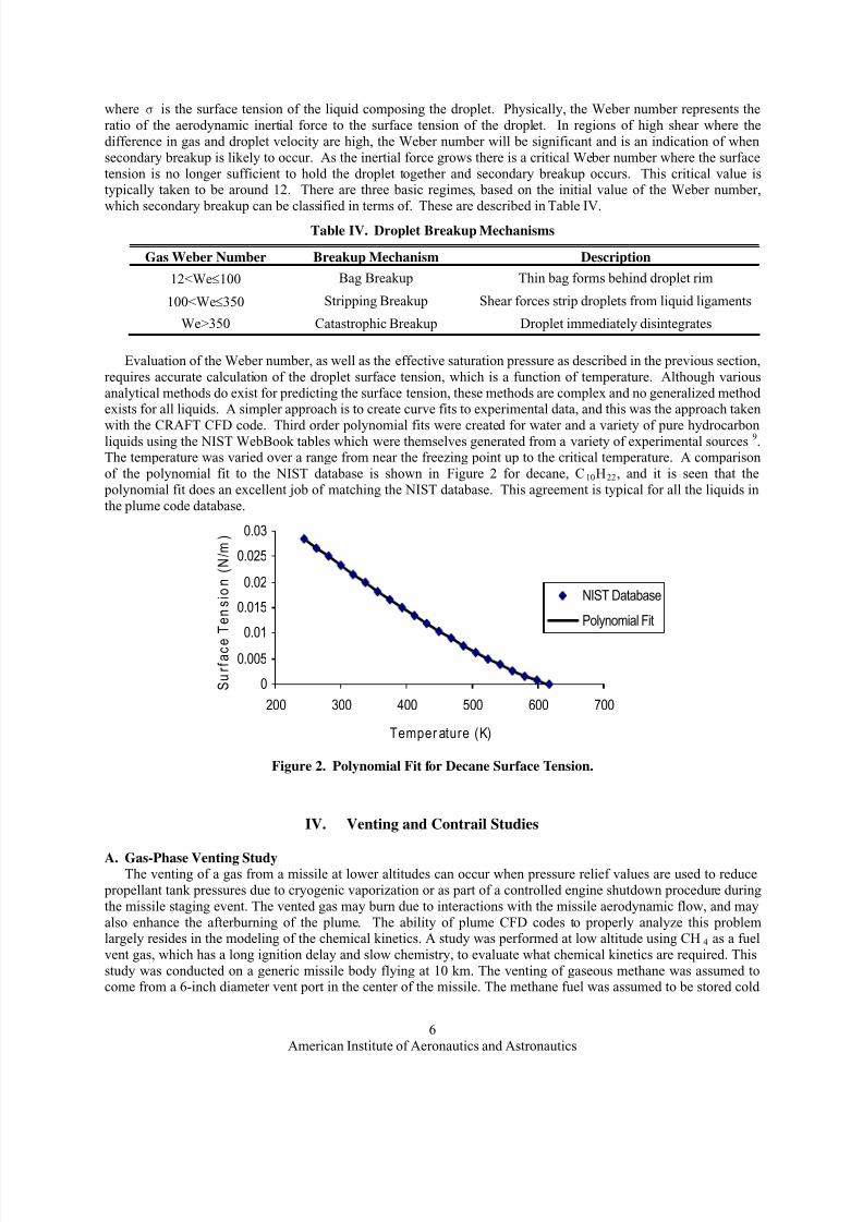
Evaluation of the Weber number, as well as the effective saturation pressure as described in the previous section,
requires accurate calculation of the droplet surface tension, which is a function of temperature. Although various
analytical methods do exist for predicting the surface tension, these methods are complex and no generalized methodexists for all liquids. A simpler approach is to create curve fits to experimental data, and this was the approach taken
with the CRAFT CFD code. Third order polynomial fits were created for water and a variety of pure hydrocarbonliquids using the NIST WebBook tables which were themselves generated from a variety of experimental sources 9.The temperature was varied over a range from near the freezing point up to the critical temperature. A comparison
of the polynomial fit to the NIST database is shown in Figure 2 for decane, C10H22, and it is seen that the
polynomial fit does an excellent job of matching the NIST database. This agreement is typical for all the liquids in
the plume code database.
0
0.005
0.01
0.015
0.02
0.025
0.03
200 300 400 500 600 700
Temper ature (K)
S u r f a c e
T e n s i o n
( N / m
)
NIST Database
Polynomial Fit
Figure 2. Polynomial Fit for Decane Surface Tension.
IV.
Venting and Contrail Studies
A.
Gas-Phase Venting StudyThe venting of a gas from a missile at lower altitudes can occur when pressure relief values are used to reduce
propellant tank pressures due to cryogenic vaporization or as part of a controlled engine shutdown procedure during
the missile staging event. The vented gas may burn due to interactions with the missile aerodynamic flow, and may
also enhance the afterburning of the plume. The ability of plume CFD codes to properly analyze this problemlargely resides in the modeling of the chemical kinetics. A study was performed at low altitude using CH 4 as a fuel
vent gas, which has a long ignition delay and slow chemistry, to evaluate what chemical kinetics are required. This
study was conducted on a generic missile body flying at 10 km. The venting of gaseous methane was assumed tocome from a 6-inch diameter vent port in the center of the missile. The methane fuel was assumed to be stored cold
American Institute of Aeronautics and Astronautics
6

8/10/2019 CFD Missile Fuel Venting and Plume AIAA-2007-1012.pdf
http://slidepdf.com/reader/full/cfd-missile-fuel-venting-and-plume-aiaa-2007-1012pdf 7/13
(300K), and at a pressure of 2 atm. Table V lists the relevant conditions for the missile, fuel, and plume
characteristics.
Table V. Free stream, plume, and Fuel Vent Orifice Reference Conditions
Free stream (O2, N2)
• Alt = 10 km
• M = 1.63• T = 233.1 K
• P = 4 psia
Vent Port (CH4)
Assumed Conditions
• 6-inch diameter hole• Sonic at hole exit
• Cold Fuel
– Total Temp 300 K
– Total Pressure 2 atm
Exhaust Plume
• M = 3
• T = 1365. K• P = 60000 Pa
• Composition (Mass Fraction)
– CO 17%
– CO2 14%
– H2 1.5%
– H2O 30%
– N2 37%
To represent the chemical kinetics of both the missile plume and methane being vented, finding a “universal”
mechanism representative of both plume afterburning and CH 4 air/plume kinetics needed to be addressed. Plumeafterburning was well represented by standardized chemistry mechanisms in plume codes (i.e., System II in SPF),
but this was not appropriate for the methane chemistry. An extended chemical kinetic system that was sufficient for
methane/air combustion ( AFRL Full Hydrocarbon Mechanism, without any of the Nitrogen based reactions) was
evaluated by using this system for the plume.
The plume only comparisons using the AFRL Full Hydrocarbon Mechanism matched very well compared to the
well calibrated System II plume chemistry package. Figure 3 shows temperature comparisons for the plume-onlycases along with comparisons of H2 mass fraction. The above simulation was then run using the Full Mechanism
with the plume on and with the methane fuel being vented. The results showed that there were obvious signs of the
vented fuel burning after being entrained into the hot plume. This is shown in Figure 4, where the top half of the plume is hotter than the lower half.
Further evidence of the vented fuel burning is found by looking at mass fractions of minor product species. CH3
is present as a product both where the fuel is vented, and at the plume in Figure 5. Presence of some minor productspecies HCO and CH2O are shown in Figure 6, and are also indicators of the vented fuel burning with the plume.
Conclusions drawn from this study are that gaseous venting effects can be detected at lower altitudes where the
fuel can burn and enhance afterburning, even with a slow burning fuel such as methane. A detailed Full Hydrocarbon Mechanism provided an effective means of modeling both the missile plume and fuel being vented
from the missile’s fuel tank. Burning was evident as the vented fuel mixed with the hot plume, and, there was aclear increase in temperature where the mixing occurred, along with the presence of product chemical species.
System II Mechanism
AFRL Full MechanismExcellent match between cases.
System II Mechanism
AFRL Full MechanismExcellent match between cases.
H2
Figure 3. Temperature Contours, and Mass Fraction of H2 Show Good Agreement for the Full Mechanism
With System II Chemistry for the Plume Only Case.
American Institute of Aeronautics and Astronautics
7

8/10/2019 CFD Missile Fuel Venting and Plume AIAA-2007-1012.pdf
http://slidepdf.com/reader/full/cfd-missile-fuel-venting-and-plume-aiaa-2007-1012pdf 8/13
Higher temperatures on upper half show
CH4 burning with missile plume.
Figure 4. Temperature Contours Show Vented Fuel Burning With Hot Plume.
CH3
CH3 isproduced at
the plume
and at the
vent
Figure 5. Product Mass Fraction of CH3 Shows Some Burning as Fuel Exits Vent Port,
and as it Mixes With the Plume.
CH4 burning is most evident by presence
of minor species (HCO).
HCO
CH4 burning is most evident by presence
of minor species (CH2O).
Figure 6. Presence of Minor Species (HCO Mass Fraction and CH2O mass Fraction) Another Indicator of
Vented Fuel Burning.
American Institute of Aeronautics and Astronautics
8
8/10/2019 CFD Missile Fuel Venting and Plume AIAA-2007-1012.pdf
http://slidepdf.com/reader/full/cfd-missile-fuel-venting-and-plume-aiaa-2007-1012pdf 9/13
B. Liquid Venting Study
An important class of problems being studied involves the discharge of a liquid jet into an aerodynamic flow.
Computationally, this type of problem involves a different set of challenges compared to gas-gas problem, due to the
large variation in fluid density and compressibility between the two phases. Furthermore, in a high shear
environment, the liquid stream can breakup into droplets, and based upon local thermodynamic conditions, couldvaporize into a gas phase. Thus, a gas-gas problem could ensue, similar to that presented in the previous example. In
this case, however, the characteristics of the jet/freestream interaction, such as jet penetration and gas mixing, could
be significantly different, depending on the liquid jet breakup. Here, we consider a gas/liquid problem and presentthe results of a simulation in which the gas/liquid interface is tracked as a first step towards a future complete
simulation including liquid jet breakup and vaporization.
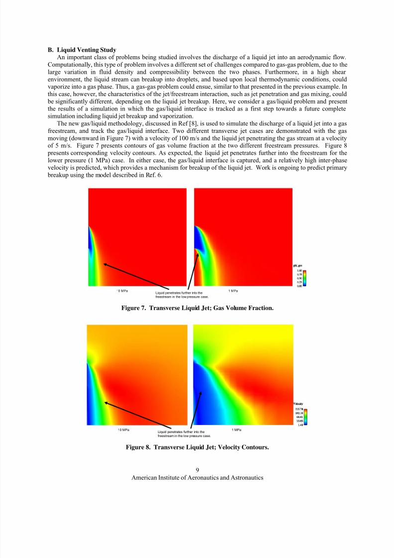
The new gas/liquid methodology, discussed in Ref [8], is used to simulate the discharge of a liquid jet into a gas
freestream, and track the gas/liquid interface. Two different transverse jet cases are demonstrated with the gas
moving (downward in Figure 7) with a velocity of 100 m/s and the liquid jet penetrating the gas stream at a velocityof 5 m/s. Figure 7 presents contours of gas volume fraction at the two different freestream pressures. Figure 8
presents corresponding velocity contours. As expected, the liquid jet penetrates further into the freestream for the
lower pressure (1 MPa) case. In either case, the gas/liquid interface is captured, and a relatively high inter-phasevelocity is predicted, which provides a mechanism for breakup of the liquid jet. Work is ongoing to predict primary
breakup using the model described in Ref. 6.
10 MPa 1 MPaLiquid penetrates further into thefreestream in the low pressure case.
Figure 7. Transverse Liquid Jet; Gas Volume Fraction.
10 MPa 1 MPaLiquid penetrates further into the
freestream in the low pressure case.
Figure 8. Transverse Liquid Jet; Velocity Contours.
American Institute of Aeronautics and Astronautics
9

8/10/2019 CFD Missile Fuel Venting and Plume AIAA-2007-1012.pdf
http://slidepdf.com/reader/full/cfd-missile-fuel-venting-and-plume-aiaa-2007-1012pdf 10/13
C. Co-Flowing Jet Liquid/Gas Simulation
The simulation of a round water jet surrounded by a high speed annular air jet was performed based on
experimental work done by Lasheras et al 10. Figure 9 shows a schematic of the problem. The simulation was run to
match one set of experimental conditions. The inner jet is a 100% liquid core by volume with a nozzle exit velocity
of 1.5 m/s. The liquid core is surrounded by an outer air jet with an exit velocity of 250 m/s. The simulations wererun at room temperature and pressure (300 K and 1 atm). This experiment also provides a good test case for the
primary breakup model that is currently under development. Presented here will be the results of the gas/liquid
methodology to capture the interface between the two phases, without breakup. Figure 10 shows the stream-wisevelocity contours of the two jets. Figure 11 shows the mass fraction contours of the liquid jet. The gas and liquid
begin to mix immediately, and the high shear between the two phases will result in liquid breakup as recorded by
Lasheras et al. 10 that will be accounted for in an ongoing study.
Liquid Jet:
Velocity = 1.5 m/s
Pressure = 1 atm
Temperature = 300 K
Liquid Volume Fraction = 100%
Air Jet:
Velocity = 250 m/s
Pressure = 1 atm
Temperature = 300 K
Liquid
Gas
Gas
3.8 mm5.6 mm
Figure 9. Schematic of Co-Annular Liquid/Gas Jet Problem.
Figure 10. Stream-Wise Velocity Contours.
Figure 11. Contours of Liquid Mass Fraction.
American Institute of Aeronautics and Astronautics
10

8/10/2019 CFD Missile Fuel Venting and Plume AIAA-2007-1012.pdf
http://slidepdf.com/reader/full/cfd-missile-fuel-venting-and-plume-aiaa-2007-1012pdf 11/13
D. Unified Secondary Breakup and Droplet Vaporization in a Transverse Jet
The previous example of a liquid jet discharging into a high-speed gas flow has the potential for liquid jet
breakup into relatively large droplets, due the primary breakup mechanism, as discussed in Ref. 9. Droplets in a
high shear environment are subject to secondary breakup which can result in further disintegration of the droplet,
based on the droplet Weber number.Considered here is the response of pre-existing droplets to the secondary breakup mechanism coupled to droplet
vaporization. The simulation compares the penetration of vented 50 micron radius droplets into a high speed stream
with (1) no secondary breakup, (2) low Weber number breakup (where a parent droplet breaks into several childdroplets, each having about 10% of the radius of the original droplet) and (3) high We number, catastrophic type
breakup (where each droplet breaks into numerous droplets, each having a radius that is 2% of the original droplet
size). The problem is shown schematically in Figure 12, with Toluene droplets injected into a Mach 2 air freestream.
Figure 13 presents the droplet radius behavior (note the difference in scales) for each case, and shows the prominent
effect of secondary breakup on droplet size. The left-hand side of Figure 14 shows the droplet cloud penetration,while the right-hand-side shows the conversion of droplets into gaseous fuel due to vaporization. The impact of
secondary breakup on droplet vaporization is clearly evident in this unit problem, as the smaller droplets provide a
larger surface-area/mass ratio, demonstrating the importance of incorporating a secondary breakup model intodroplet vaporization simulations.
Freestream Air
T∞ = 380KP∞ = 1 atmM=2.0
Air Jet w/ Toluene DropletsT j = 380K
P j = 2 atm
M=1.0Droplet Mass Fraction = 0.3
Droplet radius = 50 micron
Figure 12. Transverse Jet with Droplet Injection Schematic.
No Breakup
• r = 47 micronsmean
• Droplets penetrate freestream
Simple Breakup
• r = 5 micronsmean
• Smaller droplets are entrained more readily
Multiple Breakup
• r = 1 micronmean
• Rapid breakup
• Rapid entrainment
Figure 13. Simple Droplet Venting Example Showing Combined Effects of Secondary Breakup and
Vaporization on Droplet Radius.
American Institute of Aeronautics and Astronautics
11

8/10/2019 CFD Missile Fuel Venting and Plume AIAA-2007-1012.pdf
http://slidepdf.com/reader/full/cfd-missile-fuel-venting-and-plume-aiaa-2007-1012pdf 12/13
Particle Mass Loading C7H8 Mass Fraction
No
Breakup
Simple
Breakup
Multiple
Breakup
Figure 14. Simple Droplet Venting Example Showing Combined Effects of Secondary Breakup and
Vaporization on Droplet Cloud Penetration and Vapor Formation.
E. Contrail Formation Study
Condensation of water vapor in rocket exhaust plumes producing secondary smoke and often extended contrails
has proven difficult to model and no well established "practical" model is available in any of the newer CFD plume
codes. The approach taken in our work has entailed modifying our Eulerian droplet vaporization/condensation
model to consider a multi-component droplet, which consists of a fixed nucleus along with a variable-thicknesscondensate layer around the nucleus. This is a heterogeneous nucleation model which accounts for the high particle
number loading, typical in many rocket exhaust plumes, to provide condensation nuclei. The Sauter-mean droplet
diameter model for droplet vaporization is modified to account for the multi-component droplet, and an additional
transport equation to track dry nuclei mass distribution is incorporated to facilitate calculation of the compositedroplet material properties. The difference between the total droplet cloud density and the nucleus cloud density
provides the quantity of condensed vapor at any location in the domain, which reveals itself as secondary smoke in a
condensation trail. The ability to predict secondary smoke formation at both low and high altitudes for missile
problems is of interest for a variety of logistical reasons. Figure 15 taken from the work of Simmons11 shows
imagery associated with sunlight scattered from droplets formed in a 60km plume. Figure 16a (nearfield) and Figure
16 b (farfield) show the predicted vapor trail in a 60km plume based on application of the new secondary smoke
model.
Figure 15. Imagery of Sunlight Scattered from Condensed Water Vapor in 60km Plume (Simmons11
)
American Institute of Aeronautics and Astronautics
12

8/10/2019 CFD Missile Fuel Venting and Plume AIAA-2007-1012.pdf
http://slidepdf.com/reader/full/cfd-missile-fuel-venting-and-plume-aiaa-2007-1012pdf 13/13
(a) Nearfield (b) Farfield
Figure 16. Predicted Water Vapor Formation in 60km Plume using New Secondary Smoke Modeling.
V. Concluding Remarks
Substantial progress has been made in extending the new, engineering-oriented missile plume codes to analyze
more generalized problems entailing varied missile propulsive flowfield phenomena. Specifically, engineering
models to simulate the complete sequence of liquid jet discharge with breakup, and droplet
vaporization/condensation are being implemented to enable the prediction of multi-phase phenomena involved inapplications such as fuel venting and plume contrail formation. To analyze such processes, gas/liquid modeling
methodology is being incorporated into the plume codes to provide a robust, multiphase interface capturing
capability. Overall progress in extending the new plume codes to analyze these processes has been described in this
paper and illustrated with a series of example applications.
Acknowledgments
The work described in this paper was performed under an SBIR program entitled “Propulsion Related Missile
Phenomena” monitored by AFRL/PRSA.
References
1 York, B.J., Lee, R.A., Sinha, N. and Dash, S.M., “Progress In The Simulation of Particulates Interaction In SolidPropellant Rocket Exhaust,” AIAA-2001-3590, 37th AIAA/ASME/SAE/ASEE JPC, Salt Lake City, UT, July 8-11, 2001.
2 Papp, J.L. and Dash, S.M., “Turbulence Model Unification and Assessment for High-Speed Aeropropulsive Flows,”AIAA Paper No. 2001-0880, 39th AIAA Aerospace Sciences Meeting and Exhibit, Reno, NV, January 8-11, 2001.
3 Calhoon, W.H. and Kenzakowski, D.C., "Flowfield and Radiation Analysis of Missile Exhaust Plumes Using a
Turbulent-Chemistry Interaction Model," Paper No. AIAA-2000-3388, 36th AIAA/ASME/SAE/ASEE JPC and Exhibit, VonBraun Civic Center, Huntsville, AL, July 17-19, 2000.
4 Sinha, N., Dash, S.M., and Hosangadi, A., "Applications of an Implicit, Upwind NS Code, CRAFT, to Steady/UnsteadyReacting, Multi-Phase Jet/Plume Flowfields," AIAA Paper 92-0837, AIAA 30 th Aerospace Sciences Meeting, Reno, NV, January
6-9, 1992.
5 Hosangadi, A., Sinha, N., and Dash, S.M., "A Unified Hyperbolic Interface Capturing Scheme for Gas/Liquid Flows,"
AIAA-97-2081, 13th AIAA CFD Conferences, Snowmass, CO, June 29-July 2, 1997.
6 Tonello, N.A., Dash, S.M., and Perrell, E.R., “Advanced Computational Framework For Dynamic Bulk-Liquid GasInteractions,” AIAA Paper-99-2205, 35th AIAA/ASME/ SAE/ASEE Joint Propulsion Conference and Exhibit, Los Angeles, CA,June 20-24, 1999.
7 Hosangadi, A., and Ahuja, V., “A New Unsteady Model for Dense, Cloud Cavitation in Cryogenic Fluids,” Paper No.AIAA-2005-5347, 17th Computational Fluids Dynamic Conference, Toronto, Ontario, CA, Jun. 6-9, 2005.
8 Feldman, G., Hosangadi, A., Brinckman, K.W., and Dash, S.M., “Application of Improved Gas/Liquid Methodology toHigh Speed Venting and Bulk-Flyout Problems,” 45th Aerospace Sciences Meeting and Exhibit, Reno, NV, Jan. 8-11, 2007.
9 Lemmon, E.W., McLinden, M.O., and Friend, D.G., "Thermophysical Properties of Fluid Systems" In NIST ChemistryWebBook, NIST Standard Reference Database Number 69, Eds. P.J. Linstrom and W.G. Mallard, June 2005, National Instituteof Standards and Technology, Gaithersburg MD, 20899 (http://webbook.nist.gov).
10 Lasheras, J.C., Villermaux, E., and Hopfinger, E.J., “Break-up and atomization of a round water jet by a high-speed
annular air jet,” J. Fluid Mech, Vol. 357, pp. 351-379, 1998.
11 Simmons, F.S., “Rocket Exhaust Plume Methodology,” AeroSpace Press, El Segundo, CA, 2000.
American Institute of Aeronautics and Astronautics
13