Embed Size (px)
Citation preview
International Journal of Recent advances in Mechanical Engineering (IJMECH) Vol.4, No.3, August 2015
DOI : 10.14810/ijmech.2015.4308 99
CFD ANALYSIS OF HEAT TRANSFER
ENHANCEMENT BY USING PASSIVE
TECHNIQUE IN HEAT EXCHANGER
C Rajesh Babu and Santhosh Kumar Gugulothu
Assistant Professor, Department of Mechanical Engineering, GITAM University,
HYDERABAD, INDIA
ABSTRACT
The heat transfer enhancement is very important many engineering applications to increase the
performance of heat exchangers. The active techniques required external power like surface vibrations,
electrical fields etc and the passive techniques are those which does not required any external power but
the inserts are required to disturb the flow like tape inserts etc moreover literature survey says passive
techniques gives more heat transfer rate without external power requirement by keeping different tape
inserts. However CFD tool is very important and effective tool to understanding heat transfer applications.
Computational heat transfer flow modelling is one of the great challenges in the classical sciences. By
incorporating the inserts the heat transfer enhancement is increased due to its importance in different
applications. By CFD modelling by taking concentric tube by considering with and without inserts we
conclude that heat transfer enhancement by using ANSYS Fluent version 14.5.
KEYWORDS
Heat transfer, parallel flow heat exchanger, heat transfer agumentation, CFD Analysis, passive technique,
Reynolds no, Nussult no, twisted tape insert.
1. INTRODUCTION
Heat exchanger is a piece of equipment built for efficient heat transfer from one medium to
another. They facilitate the exchange of heat between two fluids that are at different temperatures
while keeping them from mixing with each other. Different applications of heat exchanger are
condensers, evaporators, boilers conditionation and refrigeration etc. Heat exchanger is used in
automobile radiators and coolers. Heat exchangers are also abundant in chemical and process
industries. We will consider only the more common types here for discussing some analysis and
design methodologies. Heat exchangers are popular used in industrial and engineering
applications. The design procedure of heat exchangers is quite complicated, as it
needs exact analysis of heat transfer rate, efficiency and pressure drop apart
from issues such as long- term performance and the economic aspect of the
equipment. By incorporating different techniques we conclude that heat
transfer coefficient increases with the cost of pressure drop. Heat transfer
enhancement techniques are classified as follows
International Journal of Recent advances in Mechanical Engineering (IJMECH) Vol.4, No.3, August 2015
100
1.1 Passive Techniques:
Passive techniques are geometrical change or with disturbing the fluid by keeping inserts. They
promote higher heat transfer coefficients by disturbing or altering the existing flow behaviour
(except for extended surfaces) which also leads to increase in the pressure drop. Heat transfer
augmentation achieved by following
Treated Surfaces: Treated surfaces are applicable primarily in two-phase heat transfer, and they
consist of a variety of structured surfaces (continuous or discontinuous integral surface roughness
or alterations) and coatings. In the event that this treatment provides a “roughness” to the surface,
its size (normal protrusion to the surface) is not large enough to influence single-phase forced
convection
Rough surfaces: Structured roughness can be integral to the surface, or the protuberances can be
introduced in the form of wire-coil-type inserts. The former can be produced by machining (e.g.,
knurling, threading, grooving), forming, casting, or welding, and the resulting surface
proturberances or grooves can be two dimensional or discrete three-dimensional in their
geometrical arrangement
Extended surfaces: Extended or finned surfaces are perhaps the most widely used and researched
of all enhancement techniques. Enhanced heat transfer from finned surfaces by buoyancy-driven
natural or free convection has been considered primarily for cooling of electrical and electronic
devices and for hot-water baseboard room heaters. building/room heating equipment, the use of
baseboard heaters has declined considerably; in fact, this practice is close to being discontinued.
Swirl flow devices: Swirl flow devices generally consist of a variety of tube inserts,
geometrically varied flow arrangements, and duct geometry modifications that produce secondary
flows. Typical examples of each of these techniques include twisted-tape inserts, periodic
tangential fluid injection, and helically twisted tubes.
Coiled tubes: A coiled or curved tube has long been recognized as a swirl-producing flow
geometryThe secondary fluid motion is generated essentially by the continuous change in
direction of the tangential vector to the bounding curved surface of the duct, which results in the
local deflection of the bulk flow velocity vector.
International Journal of Recent advances in Mechanical Engineering (IJMECH) Vol.4, No.3, August 2015
101
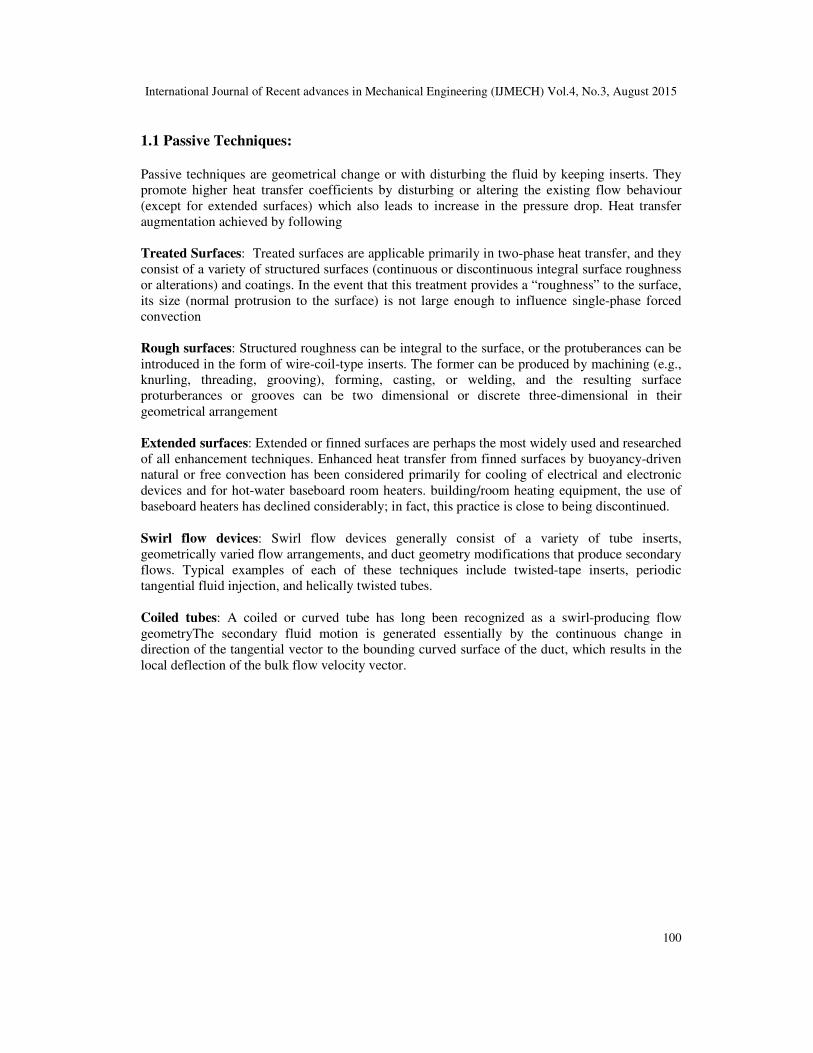
Table 1. Configuration sketches of various twisted tapes.
By incorporating helical tape inserts as literature survey says there is a heat transfer enhancement.
For the experimental set up by Reducing width of the helical twisted tape inserts with ID of inside
tube (W/di=0.675)) are shown in Table 1. Configuration sketches of various twisted tapes.
2. METHODOLOGY
Following methodology used to evaluate performance by using CFD analysis.
• Identification of flow domain
• Geometry Modeling.
• Grid generation.
• Specification of boundary Conditions.
• Selection of solver parameters and
• Convergence criteria.
• Results and post processing.
International Journal of Recent advances in Mechanical Engineering (IJMECH) Vol.4, No.3, August 2015
102
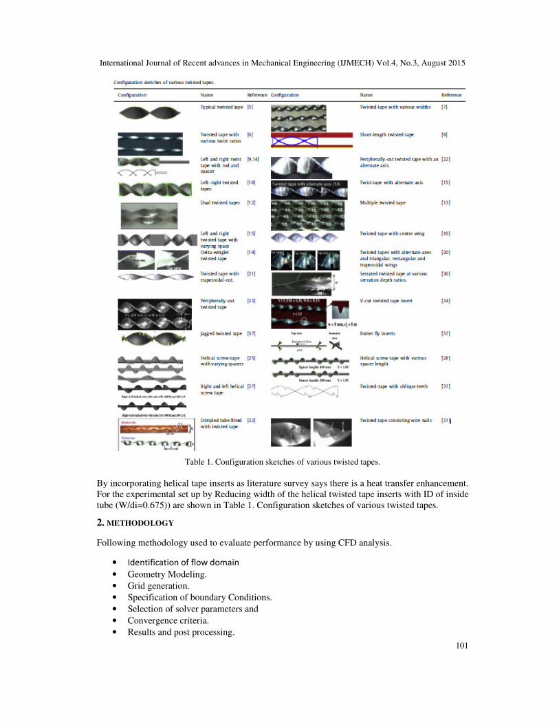
2.1 Modelling Heat exchanger is modelled using CATIA V5 software. It is an assembly of all the parts. A
concentric tube heat exchanger (with twisted tape), heat exchanger (without inserting any twisted
tape) is modelled according to the dimensions of practically available heat exchanger. Heat
exchanger with twisted tape
Figure 1. Heat exchanger with twisted tape
SpecificationsHeat exchanger
Outer diameter of the outer tube : 39mm
Inner diameter of the outer tube : 36mm
Outer diameter of the inner tube : 25mm
Inner diameter of the outer tube : 19mm
Length of the heat exchanger : 200mm
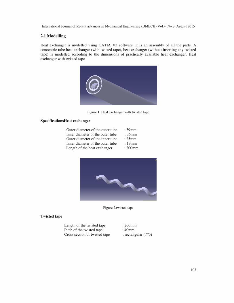
Figure 2.twisted tape
Twisted tape
Length of the twisted tape : 200mm
Pitch of the twisted tape : 40mm
Cross section of twisted tape : rectangular (7*5)
International Journal of Recent advances in Mechanical Engineering (IJMECH) Vol.4, No.3, August 2015
103
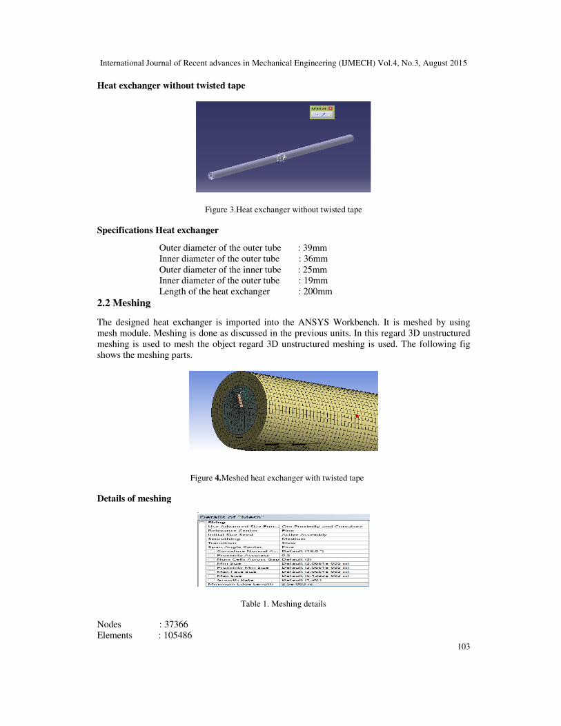
Heat exchanger without twisted tape
Figure 3.Heat exchanger without twisted tape
Specifications Heat exchanger
Outer diameter of the outer tube : 39mm
Inner diameter of the outer tube : 36mm
Outer diameter of the inner tube : 25mm
Inner diameter of the outer tube : 19mm
Length of the heat exchanger : 200mm
2.2 Meshing The designed heat exchanger is imported into the ANSYS Workbench. It is meshed by using
mesh module. Meshing is done as discussed in the previous units. In this regard 3D unstructured
meshing is used to mesh the object regard 3D unstructured meshing is used. The following fig
shows the meshing parts.
Figure 4.Meshed heat exchanger with twisted tape
Details of meshing
Table 1. Meshing details
Nodes : 37366
Elements : 105486
International Journal of Recent advances in Mechanical Engineering (IJMECH) Vol.4, No.3, August 2015
104
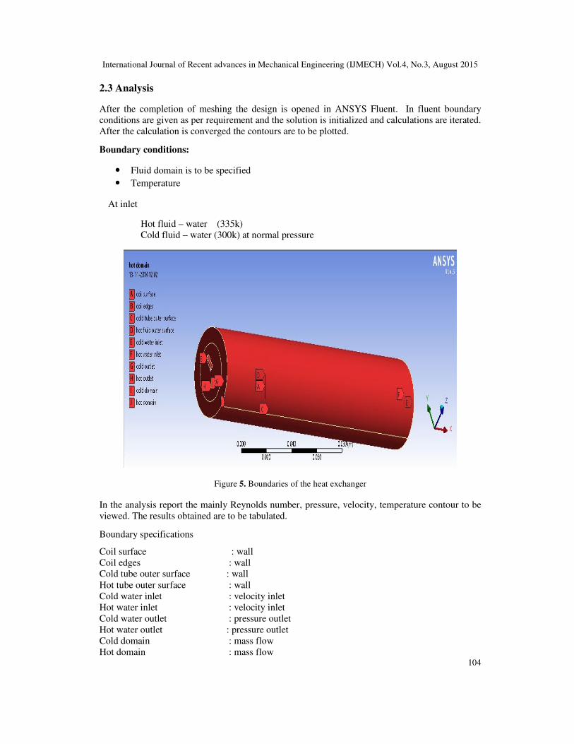
2.3 Analysis
After the completion of meshing the design is opened in ANSYS Fluent. In fluent boundary
conditions are given as per requirement and the solution is initialized and calculations are iterated.
After the calculation is converged the contours are to be plotted.
Boundary conditions:
• Fluid domain is to be specified
• Temperature
At inlet
Hot fluid – water (335k)
Cold fluid – water (300k) at normal pressure
Figure 5. Boundaries of the heat exchanger
In the analysis report the mainly Reynolds number, pressure, velocity, temperature contour to be
viewed. The results obtained are to be tabulated.
Boundary specifications
Coil surface : wall
Coil edges : wall
Cold tube outer surface : wall
Hot tube outer surface : wall
Cold water inlet : velocity inlet
Hot water inlet : velocity inlet
Cold water outlet : pressure outlet
Hot water outlet : pressure outlet
Cold domain : mass flow
Hot domain : mass flow
International Journal of Recent advances in Mechanical Engineering (IJMECH) Vol.4, No.3, August 2015
105
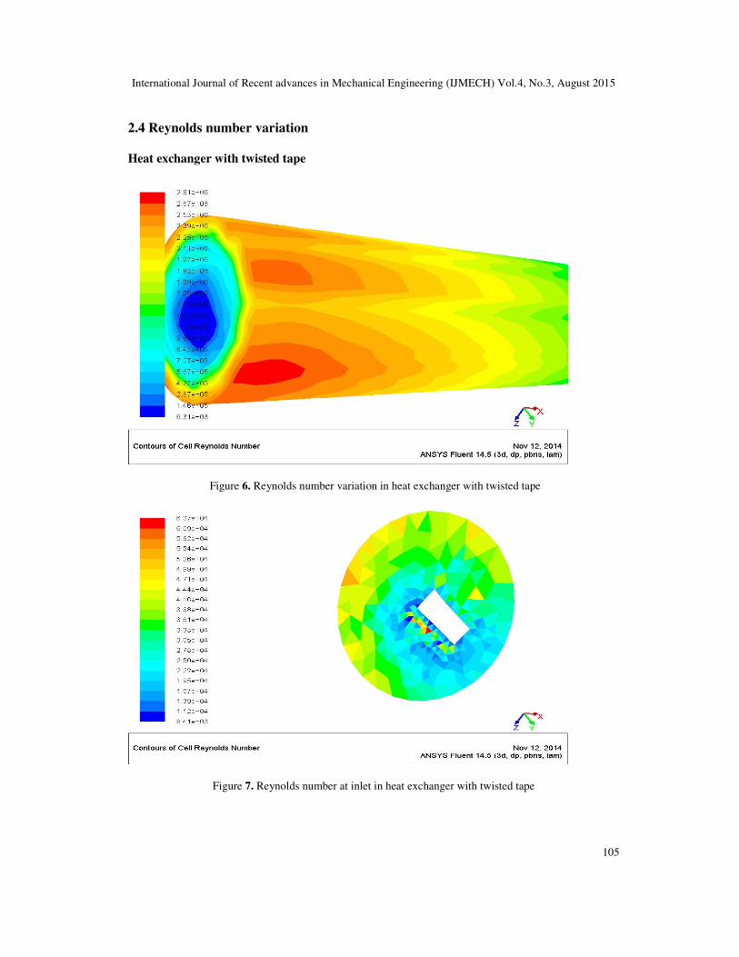
2.4 Reynolds number variation
Heat exchanger with twisted tape
Figure 6. Reynolds number variation in heat exchanger with twisted tape
Figure 7. Reynolds number at inlet in heat exchanger with twisted tape
International Journal of Recent advances in Mechanical Engineering (IJMECH) Vol.4, No.3, August 2015
106
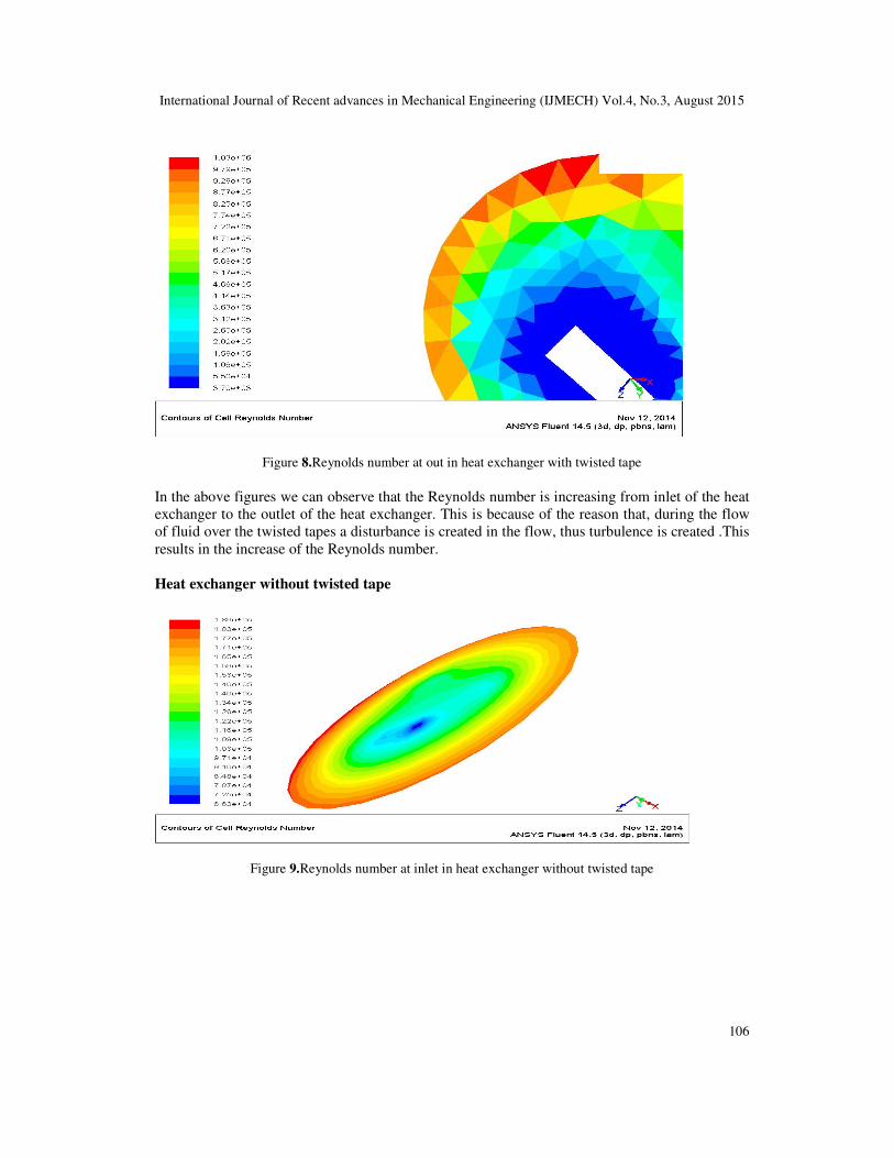
Figure 8.Reynolds number at out in heat exchanger with twisted tape
In the above figures we can observe that the Reynolds number is increasing from inlet of the heat
exchanger to the outlet of the heat exchanger. This is because of the reason that, during the flow
of fluid over the twisted tapes a disturbance is created in the flow, thus turbulence is created .This
results in the increase of the Reynolds number.
Heat exchanger without twisted tape
Figure 9.Reynolds number at inlet in heat exchanger without twisted tape
International Journal of Recent advances in Mechanical Engineering (IJMECH) Vol.4, No.3, August 2015
107
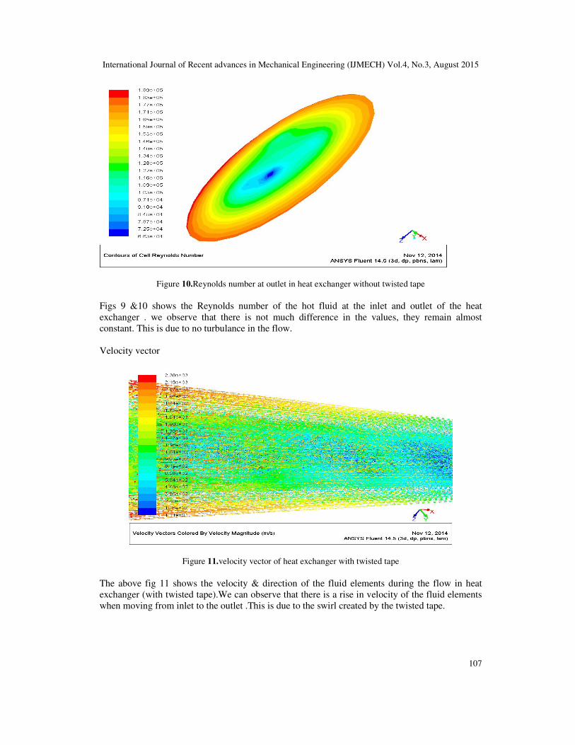
Figure 10.Reynolds number at outlet in heat exchanger without twisted tape
Figs 9 &10 shows the Reynolds number of the hot fluid at the inlet and outlet of the heat
exchanger . we observe that there is not much difference in the values, they remain almost
constant. This is due to no turbulance in the flow.
Velocity vector
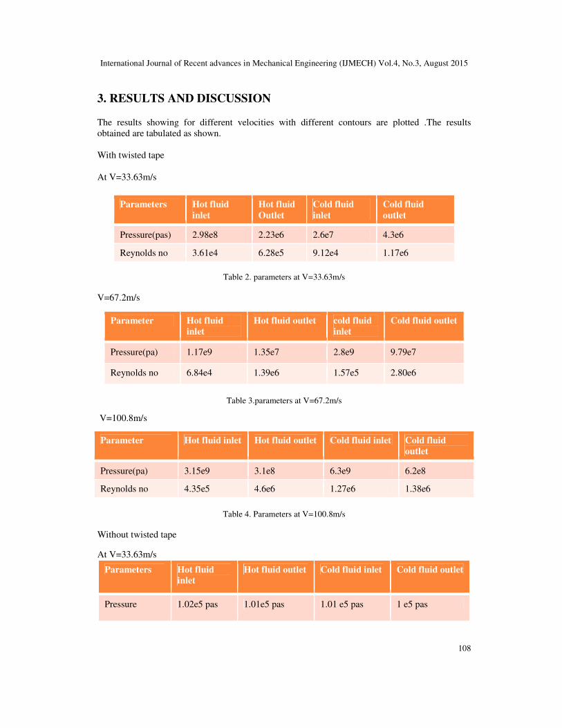
Figure 11.velocity vector of heat exchanger with twisted tape
The above fig 11 shows the velocity & direction of the fluid elements during the flow in heat
exchanger (with twisted tape).We can observe that there is a rise in velocity of the fluid elements
when moving from inlet to the outlet .This is due to the swirl created by the twisted tape.
International Journal of Recent advances in Mechanical Engineering (IJMECH) Vol.4, No.3, August 2015
108
3. RESULTS AND DISCUSSION The results showing for different velocities with different contours are plotted .The results
obtained are tabulated as shown.
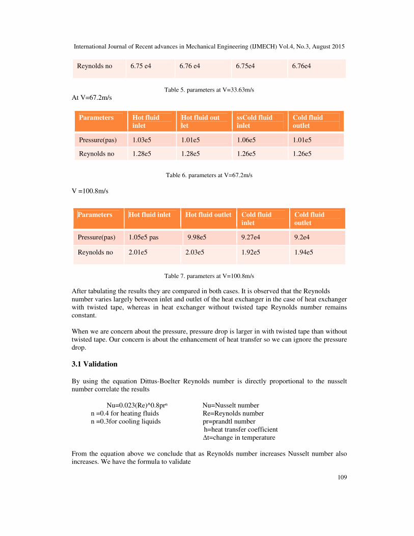
With twisted tape
At V=33.63m/s
Table 2. parameters at V=33.63m/s
V=67.2m/s
Parameter Hot fluid
inlet
Hot fluid outlet cold fluid
inlet
Cold fluid outlet
Pressure(pa) 1.17e9 1.35e7 2.8e9 9.79e7
Reynolds no 6.84e4 1.39e6 1.57e5 2.80e6
Table 3.parameters at V=67.2m/s
V=100.8m/s
Table 4. Parameters at V=100.8m/s
Without twisted tape
At V=33.63m/s
Parameters Hot fluid
inlet
Hot fluid outlet Cold fluid inlet Cold fluid outlet
Pressure 1.02e5 pas 1.01e5 pas 1.01 e5 pas 1 e5 pas
Parameters Hot fluid
inlet
Hot fluid
Outlet
Cold fluid
inlet
Cold fluid
outlet
Pressure(pas) 2.98e8 2.23e6 2.6e7 4.3e6
Reynolds no 3.61e4 6.28e5 9.12e4 1.17e6
Parameter Hot fluid inlet Hot fluid outlet Cold fluid inlet Cold fluid
outlet
Pressure(pa) 3.15e9 3.1e8 6.3e9 6.2e8
Reynolds no 4.35e5 4.6e6 1.27e6 1.38e6
International Journal of Recent advances in Mechanical Engineering (IJMECH) Vol.4, No.3, August 2015
109
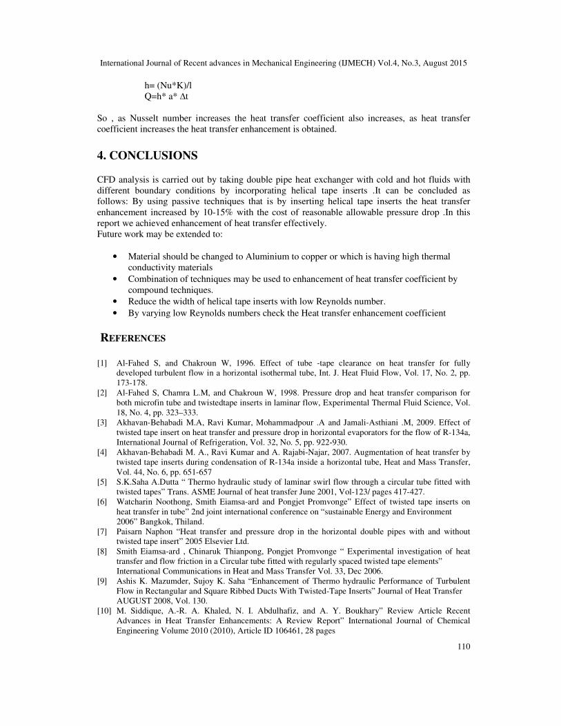
Reynolds no 6.75 e4 6.76 e4 6.75e4 6.76e4
Table 5. parameters at V=33.63m/s
At V=67.2m/s
Table 6. parameters at V=67.2m/s
V =100.8m/s
Table 7. parameters at V=100.8m/s
After tabulating the results they are compared in both cases. It is observed that the Reynolds
number varies largely between inlet and outlet of the heat exchanger in the case of heat exchanger
with twisted tape, whereas in heat exchanger without twisted tape Reynolds number remains
constant.
When we are concern about the pressure, pressure drop is larger in with twisted tape than without
twisted tape. Our concern is about the enhancement of heat transfer so we can ignore the pressure
drop.
3.1 Validation
By using the equation Dittus-Boelter Reynolds number is directly proportional to the nusselt
number correlate the results
Nu=0.023(Re)^0.8prⁿ Nu=Nusselt number
n =0.4 for heating fluids Re=Reynolds number
n =0.3for cooling liquids pr=prandtl number
h=heat transfer coefficient
∆t=change in temperature
From the equation above we conclude that as Reynolds number increases Nusselt number also
increases. We have the formula to validate
Parameters Hot fluid
inlet
Hot fluid out
let
ssCold fluid
inlet
Cold fluid
outlet
Pressure(pas) 1.03e5 1.01e5 1.06e5 1.01e5
Reynolds no 1.28e5 1.28e5 1.26e5 1.26e5
Parameters Hot fluid inlet Hot fluid outlet Cold fluid
inlet
Cold fluid
outlet
Pressure(pas) 1.05e5 pas 9.98e5 9.27e4 9.2e4
Reynolds no 2.01e5 2.03e5 1.92e5 1.94e5
International Journal of Recent advances in Mechanical Engineering (IJMECH) Vol.4, No.3, August 2015
110
h= (Nu*K)/l
Q=h* a* ∆t
So , as Nusselt number increases the heat transfer coefficient also increases, as heat transfer
coefficient increases the heat transfer enhancement is obtained.
4. CONCLUSIONS CFD analysis is carried out by taking double pipe heat exchanger with cold and hot fluids with
different boundary conditions by incorporating helical tape inserts .It can be concluded as
follows: By using passive techniques that is by inserting helical tape inserts the heat transfer
enhancement increased by 10-15% with the cost of reasonable allowable pressure drop .In this
report we achieved enhancement of heat transfer effectively.
Future work may be extended to:
• Material should be changed to Aluminium to copper or which is having high thermal
conductivity materials
• Combination of techniques may be used to enhancement of heat transfer coefficient by
compound techniques.
• Reduce the width of helical tape inserts with low Reynolds number.
• By varying low Reynolds numbers check the Heat transfer enhancement coefficient
REFERENCES
[1] Al-Fahed S, and Chakroun W, 1996. Effect of tube -tape clearance on heat transfer for fully
developed turbulent flow in a horizontal isothermal tube, Int. J. Heat Fluid Flow, Vol. 17, No. 2, pp.
173-178.
[2] Al-Fahed S, Chamra L.M, and Chakroun W, 1998. Pressure drop and heat transfer comparison for
both microfin tube and twistedtape inserts in laminar flow, Experimental Thermal Fluid Science, Vol.
18, No. 4, pp. 323–333.
[3] Akhavan-Behabadi M.A, Ravi Kumar, Mohammadpour .A and Jamali-Asthiani .M, 2009. Effect of
twisted tape insert on heat transfer and pressure drop in horizontal evaporators for the flow of R-134a,
International Journal of Refrigeration, Vol. 32, No. 5, pp. 922-930.
[4] Akhavan-Behabadi M. A., Ravi Kumar and A. Rajabi-Najar, 2007. Augmentation of heat transfer by
twisted tape inserts during condensation of R-134a inside a horizontal tube, Heat and Mass Transfer,
Vol. 44, No. 6, pp. 651-657
[5] S.K.Saha A.Dutta “ Thermo hydraulic study of laminar swirl flow through a circular tube fitted with
twisted tapes” Trans. ASME Journal of heat transfer June 2001, Vol-123/ pages 417-427.
[6] Watcharin Noothong, Smith Eiamsa-ard and Pongjet Promvonge” Effect of twisted tape inserts on
heat transfer in tube” 2nd joint international conference on “sustainable Energy and Environment
2006” Bangkok, Thiland.
[7] Paisarn Naphon “Heat transfer and pressure drop in the horizontal double pipes with and without
twisted tape insert” 2005 Elsevier Ltd.
[8] Smith Eiamsa-ard , Chinaruk Thianpong, Pongjet Promvonge “ Experimental investigation of heat
transfer and flow friction in a Circular tube fitted with regularly spaced twisted tape elements”
International Communications in Heat and Mass Transfer Vol. 33, Dec 2006.
[9] Ashis K. Mazumder, Sujoy K. Saha “Enhancement of Thermo hydraulic Performance of Turbulent
Flow in Rectangular and Square Ribbed Ducts With Twisted-Tape Inserts” Journal of Heat Transfer
AUGUST 2008, Vol. 130.
[10] M. Siddique, A.-R. A. Khaled, N. I. Abdulhafiz, and A. Y. Boukhary” Review Article Recent
Advances in Heat Transfer Enhancements: A Review Report” International Journal of Chemical
Engineering Volume 2010 (2010), Article ID 106461, 28 pages

International Journal of Recent advances in Mechanical Engineering (IJMECH) Vol.4, No.3, August 2015
111
AUTHORS
C Rajesh Babu , Assistant Professor in the Department of Mechanical Engineering,
GITAM University, Hyderabad, India.
Santhosh Kumar Gugulothu, Assistant Professor, Department of Mechanical Engineering,
GITAM University, Hyderabad, India. .