Embed Size (px)
Citation preview
CFD Analysis Of Exhaust Manifold Of Multi-Cylinder Si
Engine For Reducing Emissions With Design
Md. Zeeshan,
Student PG, Narsimha Reddy Engineering College, Hyderabad, Telangana, India.
Email: [email protected]
P. Sekhar Babu
Professor, Department of Mechanical Engineering, Narsimha Reddy Engineering College, Hyderabad,
Telangana, India.
M. Babu
Professor, Department of Mechanical Engineering, Narsimha Reddy Engineering College, Hyderabad,
Telangana, India.
Abstract- IC Engine is a vital piece of present day human culture. It may be a prosaism that IC Engines drives
human culture however for a large portion of the buzzwords it is unmistakably increasingly exact. Comprehensive
research work has occurred in the field of IC Engines and the work has proceeded as of late too. Human culture
today is confronting humongous undertakings of diminishing GHG outflows and emanations of suspended
particulate issues (SPM), SOX and NOX. Exhausting assets of regular powers has constrained us to search for
elective wellsprings of powers. IC Engines are not able enough to chip away at numerous powers. The planning of
ventilation system is a complex method and is reliant on numerous parameters viz. back weight, exhaust speed,
mechanical proficiency and so on. Inclination for any of this parameter shifts according to originators needs.
Normally efficiency, emanations and power necessity are three distinct streams or thought with respect to ventilation
system structure. This work extensively breaks down eight unique models of ventilation system and closes the most
ideal structure for least outflows and complete burning of fuel to guarantee least contamination.
Keywords: Multi-Cylinder SI Engine, Exhaust Manifold, Back Pressure, Exhaust Velocity, LBCE, LBSE, LBSER,
LBCER, SBCE, SBSE, SBCER, SBSER
I. INTRODUCTION
In an IC Engine at the start of suction stroke channel valve of chamber opens because of weight distinction. Air fuel blend (if there should be an occurrence of SI motor) or air (in the event of CI Engine) is sucked into the
chamber through this admission valve from bay complex. Gulf complex contains carburetor for blending of air
and fuel if there should be an occurrence of SI Engines. When air or air fuel blend is totally sucked into the
chamber whose cylinder has come to BDC the bay valve closes and pressure stroke starts.
As cylinder comes to TDC sparkle is touched off in the blend (SI Engines require outside starting course of
action though in CI Engine auto start happens on infusion of fuel) this denotes the start of intensity stroke. By
and by as the cylinder comes to BDC fumes stroke starts. During fumes stroke exhaust valve is opened and the
consumed blend is rejected to ventilation system. As fumes stroke is finished suction stroke starts by and by and
cycle proceeds. The vitality provided to motor in type of synthetic vitality of fuel is changed over into warm
vitality. A refined engine ought to be all around balanced and have at any rate vibrations in order to constrain
material weight and improve viability. Engine smoothness depends upon the engine arrangement as well. To
assess the motor equalization in a motor, a multi body elements recreation programming was utilized for example ADAMS/Engine controlled by FEV. Adams is a movement reproduction answer for investigating the
mind boggling conduct of mechanical congregations. It permits to test virtual models and upgrade structures
without structure and test various physical models. In this product, the primary motor parameters are
incorporated, for example, material firmness, dormancy properties, ignition weight and bearing properties.
The equalization in the motor was demonstrated and contrasted with known motor designs with
empowering results. Various stabilizers were tried in the product to locate the ideal arrangement. Here the
properties of the cylinder get together and associating bar must be built up. The crankshaft, associating bar and
cylinder get together were then demonstrated in the CAD programming CATIA , where limited component
examination was made to watch that the feelings of anxiety were adequate for the materials that would be
utilized. Figure 1 demonstrates the wrench train get together in ADAMS/Engine.
Science, Technology and Development
Volume VIII Issue XII DECEMBER 2019
ISSN : 0950-0707
Page No : 403
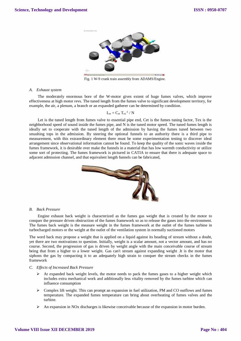
Fig. 1 W-9 crank train assembly from ADAMS/Engine.
A. Exhaust system
The moderately enormous bore of the W-motor gives extent of huge fumes valves, which improve
effectiveness at high motor revs. The tuned length from the fumes valve to significant development territory, for example, the air, a plenum, a branch or an expanded gatherer can be determined by condition.
Let = Cet Tex-1 / N
Let is the tuned length from fumes valve to essential pipe end, Cet is the fumes tuning factor, Tex is the
neighborhood speed of sound inside the fumes pipe, and N is the tuned motor speed. The tuned fumes length is
ideally set to cooperate with the tuned length of the admission by having the fumes tuned between two
smashing tops in the admission. By steering the optional funnels to an authority there is a third pipe to
measurement, with this extraordinary element there must be some experimentation testing to discover ideal
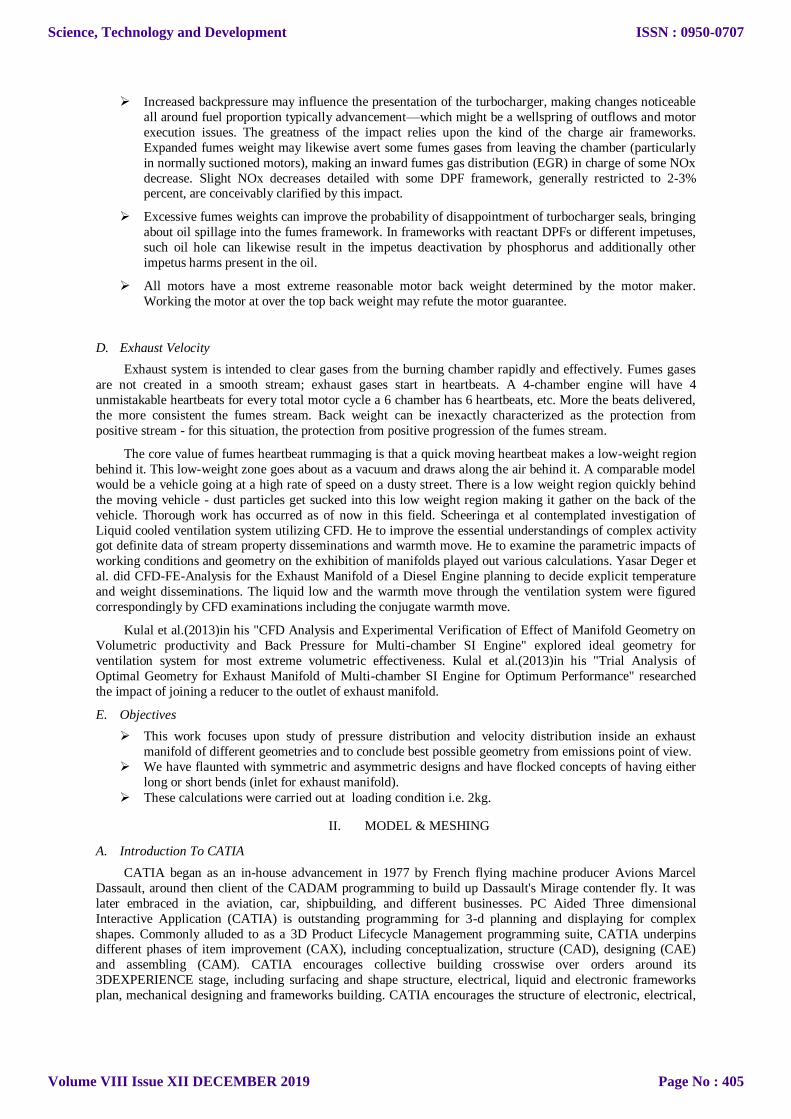
arrangement since observational information cannot be found. To keep the quality of the sonic waves inside the
fumes framework, it is desirable over make the funnels in a material that has low warmth conductivity or utilize
some sort of protecting. The fumes framework is pictured in CATIA to ensure that there is adequate space to
adjacent admission channel, and that equivalent length funnels can be fabricated,
B. Back Pressure
Engine exhaust back weight is characterized as the fumes gas weight that is created by the motor to conquer the pressure driven obstruction of the fumes framework so as to release the gases into the environment.
The fumes back weight is the measure weight in the fumes framework at the outlet of the fumes turbine in
turbocharged motors or the weight at the outlet of the ventilation system in normally suctioned motors
The word back may propose a weight that is applied on a liquid against its heading of stream without a doubt,
yet there are two motivations to question. Initially, weight is a scalar amount, not a vector amount, and has no
course. Second, the progression of gas is driven by weight angle with the main conceivable course of stream
being that from a higher to a lower weight. Gas can't stream against expanding weight .It is the motor that
siphons the gas by compacting it to an adequately high strain to conquer the stream checks in the fumes
framework
C. Effects of Increased Back Pressure
At expanded back weight levels, the motor needs to pack the fumes gases to a higher weight which
includes extra mechanical work and additionally less vitality removed by the fumes turbine which can
influence consumption
Complex lift weight. This can prompt an expansion in fuel utilization, PM and CO outflows and fumes
temperature. The expanded fumes temperature can bring about overheating of fumes valves and the
turbine.
An expansion in NOx discharges is likewise conceivable because of the expansion in motor burden.
Science, Technology and Development
Volume VIII Issue XII DECEMBER 2019
ISSN : 0950-0707
Page No : 404
Increased backpressure may influence the presentation of the turbocharger, making changes noticeable
all around fuel proportion typically advancement—which might be a wellspring of outflows and motor
execution issues. The greatness of the impact relies upon the kind of the charge air frameworks.
Expanded fumes weight may likewise avert some fumes gases from leaving the chamber (particularly
in normally suctioned motors), making an inward fumes gas distribution (EGR) in charge of some NOx
decrease. Slight NOx decreases detailed with some DPF framework, generally restricted to 2-3% percent, are conceivably clarified by this impact.
Excessive fumes weights can improve the probability of disappointment of turbocharger seals, bringing
about oil spillage into the fumes framework. In frameworks with reactant DPFs or different impetuses,
such oil hole can likewise result in the impetus deactivation by phosphorus and additionally other
impetus harms present in the oil.
All motors have a most extreme reasonable motor back weight determined by the motor maker.
Working the motor at over the top back weight may refute the motor guarantee.
D. Exhaust Velocity
Exhaust system is intended to clear gases from the burning chamber rapidly and effectively. Fumes gases
are not created in a smooth stream; exhaust gases start in heartbeats. A 4-chamber engine will have 4
unmistakable heartbeats for every total motor cycle a 6 chamber has 6 heartbeats, etc. More the beats delivered,
the more consistent the fumes stream. Back weight can be inexactly characterized as the protection from
positive stream - for this situation, the protection from positive progression of the fumes stream.
The core value of fumes heartbeat rummaging is that a quick moving heartbeat makes a low-weight region
behind it. This low-weight zone goes about as a vacuum and draws along the air behind it. A comparable model
would be a vehicle going at a high rate of speed on a dusty street. There is a low weight region quickly behind
the moving vehicle - dust particles get sucked into this low weight region making it gather on the back of the
vehicle. Thorough work has occurred as of now in this field. Scheeringa et al contemplated investigation of
Liquid cooled ventilation system utilizing CFD. He to improve the essential understandings of complex activity got definite data of stream property disseminations and warmth move. He to examine the parametric impacts of
working conditions and geometry on the exhibition of manifolds played out various calculations. Yasar Deger et
al. did CFD-FE-Analysis for the Exhaust Manifold of a Diesel Engine planning to decide explicit temperature
and weight disseminations. The liquid low and the warmth move through the ventilation system were figured
correspondingly by CFD examinations including the conjugate warmth move.
Kulal et al.(2013)in his "CFD Analysis and Experimental Verification of Effect of Manifold Geometry on
Volumetric productivity and Back Pressure for Multi-chamber SI Engine" explored ideal geometry for
ventilation system for most extreme volumetric effectiveness. Kulal et al.(2013)in his "Trial Analysis of
Optimal Geometry for Exhaust Manifold of Multi-chamber SI Engine for Optimum Performance" researched
the impact of joining a reducer to the outlet of exhaust manifold.
E. Objectives
This work focuses upon study of pressure distribution and velocity distribution inside an exhaust
manifold of different geometries and to conclude best possible geometry from emissions point of view.
We have flaunted with symmetric and asymmetric designs and have flocked concepts of having either
long or short bends (inlet for exhaust manifold).
These calculations were carried out at loading condition i.e. 2kg.
II. MODEL & MESHING
A. Introduction To CATIA
CATIA began as an in-house advancement in 1977 by French flying machine producer Avions Marcel
Dassault, around then client of the CADAM programming to build up Dassault's Mirage contender fly. It was
later embraced in the aviation, car, shipbuilding, and different businesses. PC Aided Three dimensional
Interactive Application (CATIA) is outstanding programming for 3-d planning and displaying for complex
shapes. Commonly alluded to as a 3D Product Lifecycle Management programming suite, CATIA underpins different phases of item improvement (CAX), including conceptualization, structure (CAD), designing (CAE)
and assembling (CAM). CATIA encourages collective building crosswise over orders around its
3DEXPERIENCE stage, including surfacing and shape structure, electrical, liquid and electronic frameworks
plan, mechanical designing and frameworks building. CATIA encourages the structure of electronic, electrical,
Science, Technology and Development
Volume VIII Issue XII DECEMBER 2019
ISSN : 0950-0707
Page No : 405
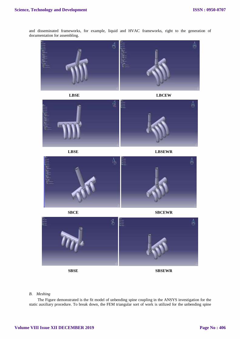
and disseminated frameworks, for example, liquid and HVAC frameworks, right to the generation of
documentation for assembling.
LBSE LBCEW
LBSE LBSEWR
SBCE SBCEWR
SBSE SBSEWR
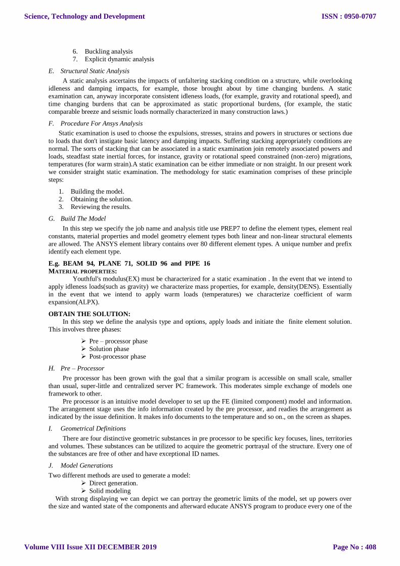
B. Meshing
The Figure demonstrated is the fit model of unbending spine coupling in the ANSYS investigation for the static auxiliary procedure. To break down, the FEM triangular sort of work is utilized for the unbending spine
Science, Technology and Development
Volume VIII Issue XII DECEMBER 2019
ISSN : 0950-0707
Page No : 406

coupling in the ANSYS condition. The quantity of components utilized in this cross section is 71441and the
quantity of hubs is 122228.In this procedure customary sort of lattice is done to investigate the procedure.
Utilizing the working state of the coupling a relative rotational development between the poles comes into
picture subsequently. The assurance of the shear worry along the contact locale is fundamental. In this way, the
model is fit and after that broke down to get the detail and valid aftereffect of the worries of the contact district.
III. ANALYSIS
A. Introduction To ANSYS
REDUCING THE DESIGN AND MANUFACTURING COSTS USING ANSYS (FEA):
The ANSYS program enables architects to develop PC models or move CAD models of structures, items,
parts, or frameworks, apply burdens or other plan execution conditions and concentrate physical reactions, for
example, feelings of anxiety, temperature dissemination or the effect of lector attractive fields.
In certain conditions, model testing is unwanted or unimaginable. The ANSYS program has been utilized
in a few instances of this sort including biomechanical applications, for example, high substitution intraocular
focal points. Other delegate applications go from substantial hardware segments, to an incorporated circuit chip,
to the bit-holding arrangement of a nonstop coal-mining machine.
ANSYS structure streamlining empowers the specialists to lessen the quantity of expensive models, tailor
unbending nature and adaptability to meet targets and locate the correct adjusting geometric alterations.
Focused organizations search for approaches to create the most elevated quality item at the least expense. ANSYS (FEA) can help fundamentally by diminishing the structure and assembling costs and by giving
specialists included trust in the items they plan. FEA is best when utilized at the applied plan arrange. It is
additionally helpful when utilized later in assembling procedure to confirm the last plan before prototyping.
B. Program Availability
The ANSYS program operates on 486 and Pentium based PCs running on Wndows95 or Windows NT and
workstations and super computers primarily running on UNIX operating system. ANSYS Inc. continually works with new hardware platforms and operating systems.
C. Analysis Types Available
Structural static analysis.
Structural dynamic analysis.
Structural buckling analysis.
o Linear buckling
o Nonlinear buckling
Structural non linearities
Static and dynamic
kinematics analysis.
Thermal analysis.
Electromagnetic field analysis.
Electric field analysis
Fluid flow analysis
Computational fluid dynamics
Pipe flow
Coupled-field analysis
Piezoelectric analysis.
D. Types Of Structural Analysis
Structural investigation is the most widely recognized utilization of the limited component strategy. The term
auxiliary (or structure) suggests structural designing structures, for example, extensions and structures, yet
additionally maritime, aeronautical and mechanical structures, for example, transport bodies, airplane bodies
and machines lodgings just as mechanical segments, for example, cylinders, machine parts and devices. There
are seven kinds of basic examinations accessible in ANSYS. One can play out the accompanying sorts of
auxiliary investigations. Every one of these examination types are talked about in detail as pursues.
1. Static analysis
2. Modal analysis 3. Harmonic analysis
4. Transient dynamic analysis
5. Spectrum analysis
Science, Technology and Development
Volume VIII Issue XII DECEMBER 2019
ISSN : 0950-0707
Page No : 407
6. Buckling analysis
7. Explicit dynamic analysis
E. Structural Static Analysis
A static analysis ascertains the impacts of unfaltering stacking condition on a structure, while overlooking
idleness and damping impacts, for example, those brought about by time changing burdens. A static
examination can, anyway incorporate consistent idleness loads, (for example, gravity and rotational speed), and
time changing burdens that can be approximated as static proportional burdens, (for example, the static
comparable breeze and seismic loads normally characterized in many construction laws.)
F. Procedure For Ansys Analysis
Static examination is used to choose the expulsions, stresses, strains and powers in structures or sections due
to loads that don't instigate basic latency and damping impacts. Suffering stacking appropriately conditions are
normal. The sorts of stacking that can be associated in a static examination join remotely associated powers and
loads, steadfast state inertial forces, for instance, gravity or rotational speed constrained (non-zero) migrations,
temperatures (for warm strain).A static examination can be either immediate or non straight. In our present work
we consider straight static examination. The methodology for static examination comprises of these principle
steps:
1. Building the model.
2. Obtaining the solution. 3. Reviewing the results.
G. Build The Model
In this step we specify the job name and analysis title use PREP7 to define the element types, element real
constants, material properties and model geometry element types both linear and non-linear structural elements
are allowed. The ANSYS element library contains over 80 different element types. A unique number and prefix identify each element type.
E.g. BEAM 94, PLANE 71, SOLID 96 and PIPE 16
MATERIAL PROPERTIES:
Youthful's modulus(EX) must be characterized for a static examination . In the event that we intend to
apply idleness loads(such as gravity) we characterize mass properties, for example, density(DENS). Essentially
in the event that we intend to apply warm loads (temperatures) we characterize coefficient of warm
expansion(ALPX).
OBTAIN THE SOLUTION:
In this step we define the analysis type and options, apply loads and initiate the finite element solution.
This involves three phases:
Pre – processor phase
Solution phase Post-processor phase
H. Pre – Processor
Pre processor has been grown with the goal that a similar program is accessible on small scale, smaller
than usual, super-little and centralized server PC framework. This moderates simple exchange of models one
framework to other.
Pre processor is an intuitive model developer to set up the FE (limited component) model and information. The arrangement stage uses the info information created by the pre processor, and readies the arrangement as
indicated by the issue definition. It makes info documents to the temperature and so on., on the screen as shapes.
I. Geometrical Definitions
There are four distinctive geometric substances in pre processor to be specific key focuses, lines, territories
and volumes. These substances can be utilized to acquire the geometric portrayal of the structure. Every one of the substances are free of other and have exceptional ID names.
J. Model Generations
Two different methods are used to generate a model:
Direct generation.
Solid modeling
With strong displaying we can depict we can portray the geometric limits of the model, set up powers over the size and wanted state of the components and afterward educate ANSYS program to produce every one of the
Science, Technology and Development
Volume VIII Issue XII DECEMBER 2019
ISSN : 0950-0707
Page No : 408
hubs and components consequently. On the other hand, with the immediate age technique, we decide the area of
each hub and size, shape and availability of each component before characterizing these elements in the ANSYS
model. Albeit, some programmed information age is conceivable (by utilizing directions, for example, FILL,
NGEN, EGEN and so on) the immediate age technique basically a hands on numerical strategy that expects us
to monitor all the hub numbers as we build up the limited component work. This itemized accounting can end
up hard for huge models, giving extension for demonstrating mistakes. Strong displaying is normally more dominant and adaptable than direct age and is ordinarily favored strategy for producing a model.
THE FOLLOWING TABLE SHOWS THE BRIEF DESCRIPTION OF STEPS FOLLOWED IN EACH PHASE
K. Mesh Generation
In the limited component examination the fundamental idea is to break down the structure, which is an
array of discrete pieces called components, which are associated, together at a limited number of focuses called
Nodes. Stacking limit conditions are then connected to these components and hubs. A system of these
components is known as Mesh.
Limited ELEMENT GENERATION: The most extreme measure of time in a limited component examination is spent on producing components and nodal information. Pre processor enables the client to produce hubs and
components consequently in the meantime permitting authority over size and number of components. There are
different sorts of components that can be mapped or created on different geometric substances.
The components created by different programmed component age capacities of pre processor can be
checked component attributes that may should be confirmed before the limited component examination for
availability, twisting list, and so forth.
By and large, programmed work creating capacities of pre processor are utilized as opposed to
characterizing the hubs separately. Whenever required, hubs can be characterized effectively by characterizing
the assignments or by deciphering the current hubs. Additionally one can plot, erase, or search hubs.
Limit CONDITIONS AND LOADING:
After finish of the limited component model it needs to oblige and load must be connected to the model. Client can characterize imperatives and loads in different ways. All imperatives and burdens are appointed set
1D. This causes the client to monitor burden cases.
Science, Technology and Development
Volume VIII Issue XII DECEMBER 2019
ISSN : 0950-0707
Page No : 409
L. Model Display
During the development and confirmation phases of the model it might be important to see it from various
points. It is helpful to pivot the model concerning the worldwide framework and view it from various edges. Pre
processor offers this capacity. By windowing highlight pre processor enables the client to amplify a particular
region of the model for lucidity and subtleties. Pre processor likewise gives highlights like smoothness, scaling,
districts, dynamic set, and so on for proficient model survey and altering.
M. Material Definitions
All components are characterized by hubs, which have just their area characterized. On account of plate
and shell components there is no sign of thickness. This thickness can be given as component property. Property
tables for a specific property set 1-D must be input. Various sorts of components have various properties for
example
Beams: Cross sectional area, moment of inertia etc
Shells: Thickness
Springs : Stiffness
Solids : None
The user also needs to define material properties of the elements. For linear static analysis, modules of
elasticity and Poisson’s ratio need to be provided. For heat transfer, coefficient of thermal expansion, densities
etc are required. They can be given to the elements by the material property se to 1-D.
IV. MATERIALS AND METHODS
Material Fluid Properties
Exhaust gas will be considered as an incompressible fluid operating at 230‐280 0C. The material properties
under these conditions are
Table 2: Material Fluid Properties
Material Air + Gasoline
Density (kg/m3) 1.0685
Viscosity (Pa-s) 3.0927 x 10‐5
Specific heat (J/kg-K) 1056.6434
Thermal conductivity 0.0250
Boundary Conditions
The inlet mass flow rates for different models at six different loading conditions are given below using these
mass flow rates the pressure and velocity contours were obtained.
Table 3: Inlet Mass Flow Rate
Load Inlet 1 Inlet 2 Inlet 3 Inlet 4
2 KG 0.000424 Kg/s 0.000424 Kg/s 0.000424 Kg/s 0.000424 Kg/s
CFD Analysis of Exhaust Manifold of Multi-Cylinder SI Engine to Determine Optimal Geometry for Reducing
Emissions:
Table 4: Inlet Mean Hydraulic Diameter
Boundary Mean Hydraulic Diameter
INLET 1 1 0.00877m
INLET 2 2 0.00877m
INLET 3 3 0.00877m
INLET 4 4 0.00877m
Outlet pressure was taken as 0atm (Gauge) for all models. The mean hydraulic diameter for outlets of different
models are shown below:
Table 5: Outlet Mean Hydraulic Diameter
Model Mean Hydraulic Diameter
Short Bend Center Exit (SBCE) 0.01302m
Short Bend Side Exit (SBSE) 0.01302m
Science, Technology and Development
Volume VIII Issue XII DECEMBER 2019
ISSN : 0950-0707
Page No : 410

Long Bend Center Exit (LBCE) 0.01302m
Long Bend Side Exit (LBSE) 0.01302m
Short Bend Center Exit with Reducer
(SBCER)
0.0095m
Short Bend Side Exit with Reducer
(SBSER)
0.0095m
Long Bend Center Exit with Reducer
(LBCER)
0.0095m
Long Bend Side Exit with Reducer
(LBSER)
0.0095m
Engine Specifications
Following engine parameters were considered for calculation of mass flow rate at different loading conditions.
The flow through exhaust manifold was considered density
based.
Table 6: Engine Specification
Engine 4 Stroke 4 Cylinder SI Engine
Make Maruti-Suzuki Wagon-R
Calorific Value of Fuel (Gasoline) 45208 KJ/Kg-K
Specific Gravity of Fuel 0.7 gm/cc
Bore and Stroke 69.05 mm X 73.40 mm
Swept Volume 1100 cc
Compression Ratio 7.2 :1
Meshing of long bend center exit
Figure shows Pressure stream line
Figure shows velocity stream line
Science, Technology and Development
Volume VIII Issue XII DECEMBER 2019
ISSN : 0950-0707
Page No : 411

Meshing of long bend center exit with reducer
Pressure
Velocity
Long bend side exit
Pressure
Velocity
Science, Technology and Development
Volume VIII Issue XII DECEMBER 2019
ISSN : 0950-0707
Page No : 412
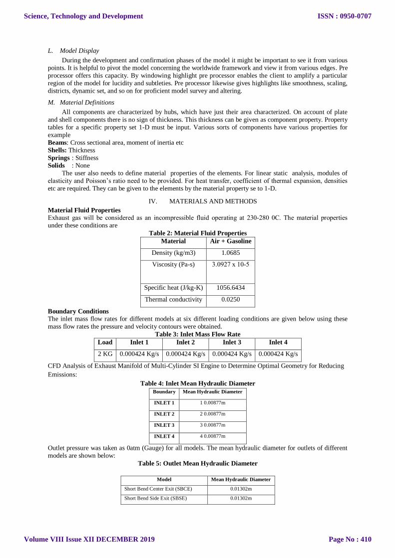
Long bend exit with reducer
Pressure
Velocity
Mesh of short bend center exit
Pressure
Science, Technology and Development
Volume VIII Issue XII DECEMBER 2019
ISSN : 0950-0707
Page No : 413

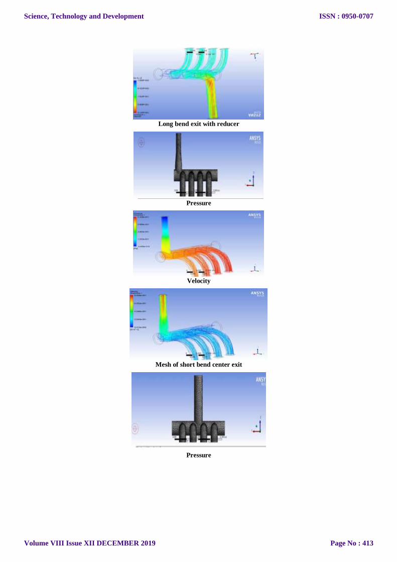
Velocity
Mesh of short bend center exit with reducer
Pressure
Velocity
Short bend side exit
Pressure
Science, Technology and Development
Volume VIII Issue XII DECEMBER 2019
ISSN : 0950-0707
Page No : 414
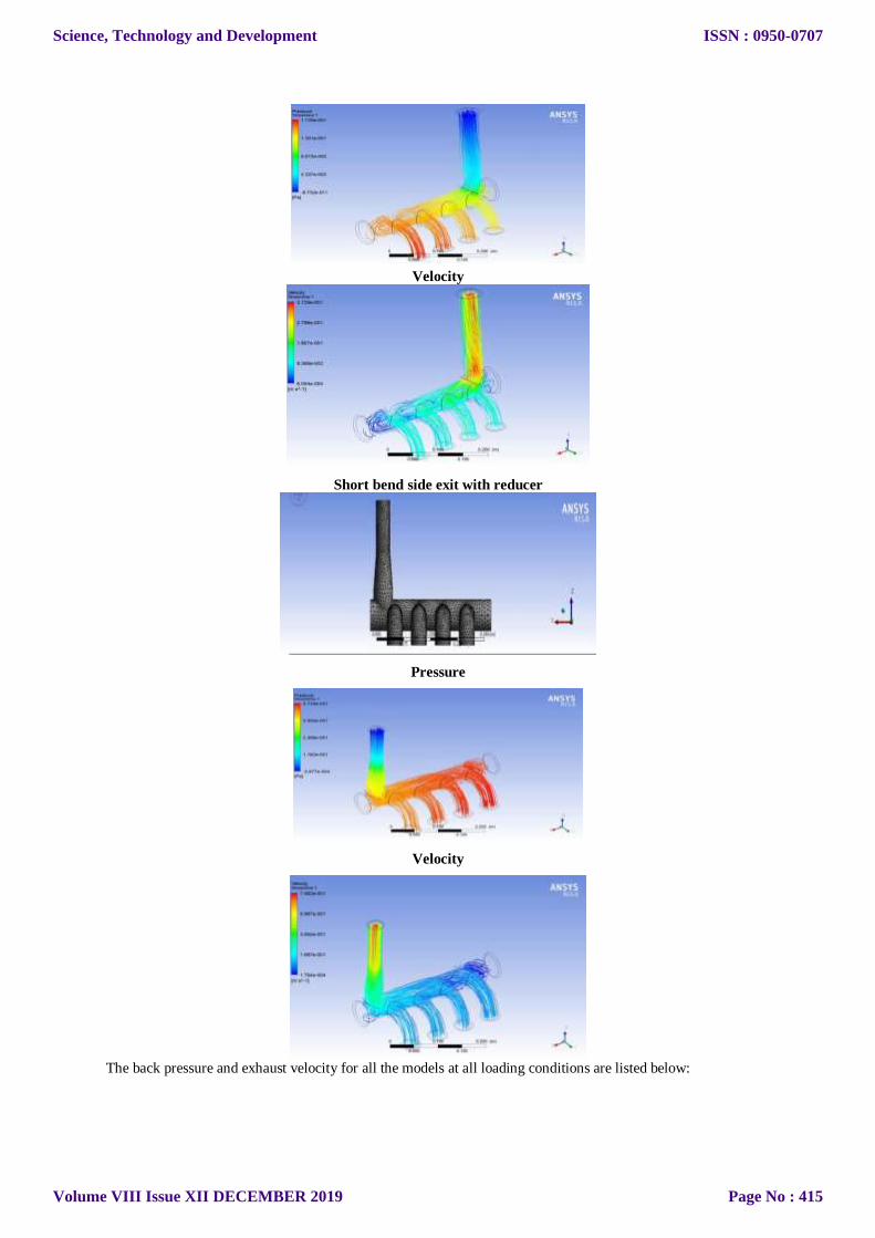
Velocity
Short bend side exit with reducer
Pressure
Velocity
The back pressure and exhaust velocity for all the models at all loading conditions are listed below:
Science, Technology and Development
Volume VIII Issue XII DECEMBER 2019
ISSN : 0950-0707
Page No : 415
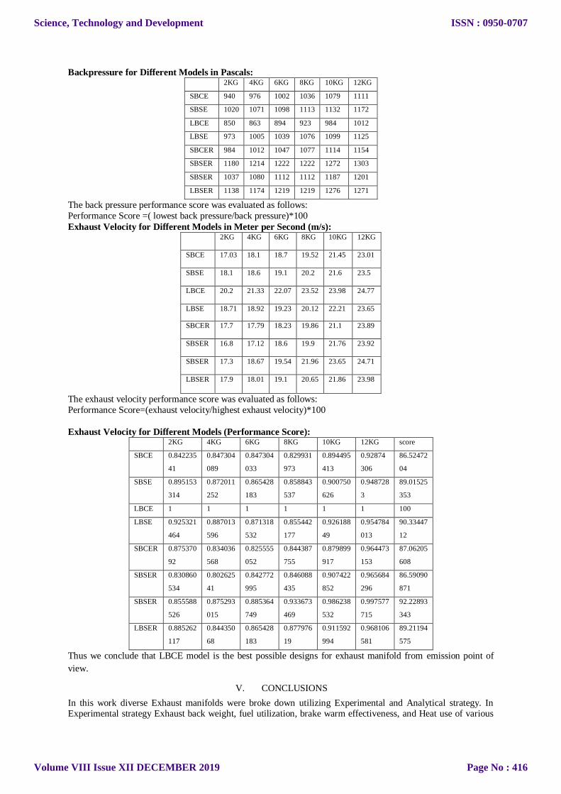
Backpressure for Different Models in Pascals: 2KG 4KG 6KG 8KG 10KG 12KG
SBCE 940 976 1002 1036 1079 1111
SBSE 1020 1071 1098 1113 1132 1172
LBCE 850 863 894 923 984 1012
LBSE 973 1005 1039 1076 1099 1125
SBCER 984 1012 1047 1077 1114 1154
SBSER 1180 1214 1222 1222 1272 1303
SBSER 1037 1080 1112 1112 1187 1201
LBSER 1138 1174 1219 1219 1276 1271
The back pressure performance score was evaluated as follows:
Performance Score =( lowest back pressure/back pressure)*100
Exhaust Velocity for Different Models in Meter per Second (m/s): 2KG 4KG 6KG 8KG 10KG 12KG
SBCE 17.03 18.1 18.7 19.52 21.45 23.01
SBSE 18.1 18.6 19.1 20.2 21.6 23.5
LBCE 20.2 21.33 22.07 23.52 23.98 24.77
LBSE 18.71 18.92 19.23 20.12 22.21 23.65
SBCER 17.7 17.79 18.23 19.86 21.1 23.89
SBSER 16.8 17.12 18.6 19.9 21.76 23.92
SBSER 17.3 18.67 19.54 21.96 23.65 24.71
LBSER 17.9 18.01 19.1 20.65 21.86 23.98
The exhaust velocity performance score was evaluated as follows:
Performance Score=(exhaust velocity/highest exhaust velocity)*100
Exhaust Velocity for Different Models (Performance Score): 2KG 4KG 6KG 8KG 10KG 12KG score
SBCE 0.842235
41
0.847304
089
0.847304
033
0.829931
973
0.894495
413
0.92874
306
86.52472
04
SBSE 0.895153
314
0.872011
252
0.865428
183
0.858843
537
0.900750
626
0.948728
3
89.01525
353
LBCE 1 1 1 1 1 1 100
LBSE 0.925321
464
0.887013
596
0.871318
532
0.855442
177
0.926188
49
0.954784
013
90.33447
12
SBCER 0.875370
92
0.834036
568
0.825555
052
0.844387
755
0.879899
917
0.964473
153
87.06205
608
SBSER 0.830860
534
0.802625
41
0.842772
995
0.846088
435
0.907422
852
0.965684
296
86.59090
871
SBSER 0.855588
526
0.875293
015
0.885364
749
0.933673
469
0.986238
532
0.997577
715
92.22893
343
LBSER 0.885262
117
0.844350
68
0.865428
183
0.877976
19
0.911592
994
0.968106
581
89.21194
575
Thus we conclude that LBCE model is the best possible designs for exhaust manifold from emission point of
view.
V. CONCLUSIONS
In this work diverse Exhaust manifolds were broke down utilizing Experimental and Analytical strategy. In Experimental strategy Exhaust back weight, fuel utilization, brake warm effectiveness, and Heat use of various
Science, Technology and Development
Volume VIII Issue XII DECEMBER 2019
ISSN : 0950-0707
Page No : 416

Manifolds on changing burden were watched. In systematic technique speed and weight dissemination along the
length of ventilation system is gotten through reproduction. Three distinct models planned and results were
dissected Thus we conclude that LBCE model is the best possible designs for exhaust manifold from emission
point of view. to discover weights and speeds at different mass stream rates in the ventilation systems with Long
Bend Side Exit (LBSE), Long Bend Middle Exit (LBME) and Reducer and discover the execution of the
ventilation system with different alterations in its plan or including a part for the ventilation system to expand its adequacy. In the present investigation mass stream rates considered in the ventilation system are 2 kg/s, 4 kg/s, 6
kg/s, 8 kg/s ,10 kg/s, 12 kg/s in all the different changes in the ventilation systems. From the above
examinations it is discovered that Long Bend Middle Exit (LBME) with Reducer is giving the better execution.
Long twist model encourages simple progression of fumes gases and low back weight at the fumes
outlet in examinations with all other two models.
The base back weight and higher fumes speeds are accomplished by utilizing long twist Ventilation
system.
Speed at the outlet of long curve model is more and consequently the back weight lessens impressively
The level of unaccounted warmth is diminished impressively when utilize long curve fumes model than
other two models
Brake warm proficiency is a greater amount of long twist fumes model in examination with sharp twist
and short twist
Fuel utilization rate diminishes when utilized long twist fumes model. REFERENCE:
[1]. Umesh K. S, Pravin V. K, and Rajagopal K. “CFD Analysis and Experimental Verification of Effect of
Manifold Geometry on Volumetric Efficiency and Backpressure for Multi-cylinder SI Engine” International
Journal of Engineering and Science Research, 3, 7, 342-353. 2013.
[2]. Umesh K. S, Pravin V. K, and Rajagopal K. “Experimental Analysis of Optimal Geometry for Exhaust
Manifold of Multi-cylinder SI Engine for Optimum Performance” International Journal of Automobile
Engineering Research and Development, 3, 4, 11-12. 2013.
[3]. Umesh K. S, Pravin V. K, and Rajagopal K. “Experimental Investigation of Various Exhaust Manifold
Designs and Comparison of Engine Performance Parameters for These to Determine Optimal Exhaust Manifold
Design for Various Applications” ACEEE Conference Proceedings Series, 2, 711-730. 2013. [4]. Jain Sweta, Agrawal AlkaBani, “Coupled Thermal – Structural Finite Element Analysis for Exhaust
Manifold of an Off-road Vehicle Diesel Engine” International Journal of Soft Computing and Engineering
(IJSCE) ISSN: 2231-2307, Volume-3, Issue-4, September 2013.
[5]. Kutaiba J.M. AL-Khishali, Mahmoud A. Mashkour & Ehsan Shamil Omaraa, “Analysis of Flow
Characteristics in Inlet and Exhaust Manifolds of Experimental Gasoline Combustion in A VCR Engine” Eng.
& Tech. Journal, Vol. 28, No. 7, 2010.
[6]. Rathnaraj, J.David “Thermomechanical Fatigue Analysis Of Stainless Steel Exhaust Manifolds” IRACST –
Engineering Science and Technology: An International Journal (ESTIJ), ISSN: 2250-3498, Vol.2, No. 2, April
20
[7]. Satish Swathi, Prithiviraj Mani and Hari Sridhar, “Comparison of predictions obtained on an exhaust
manifold analysis using conformal and indirect mapped interface” International Congress on Computational Mechanics and Simulation (ICCMS), IIT Hyderabad, 10-12 December 2012.
[8]. Mesut DURAT, Zekeriya PARLAK, Murat KAPSIZ, Adnan PARLAK, ve Ferit FIÇICI (2013) “CFD and
Experimental Analysis on Thermal Performance of Exhaust System of A Spark Ignition Engine” Isı Bilimi ve
Tekniği Dergisi, 33, 2, 89-99, 2013, J. of Thermal Science and Technology, ©2013 TIBTD Printed in Turkey,
ISSN 1300-3615
[9]. ĽUBOMÍR MIKLÁNEK (2006) “Distortion of Measured Pressure in Exhaust-manifold due to Transducer
Position” Josef Božek Research Centre, Czech Technical University in Prague, Czech Republic.
[10]. Saïd Zidat and Michael Parmentier , “Exhaust Manifold Design to Minimize Catalyst Light-off Time”
2003 SAE World Congress Detroit, Michigan March 3-6, 2003.
[11]. Kandylas, I.P., Stamatelos, A.M. “Engine exhaust system design based on heat transfer computation”
Energy Conversion & Management 40 (1999) 1057-1072. [12]. Chowdavaram Sai Prasad, Babu,M & Sachin S Raj, 2018 ‘Thermal Analysis on Exhaust Valve With
Thermal Barrier Material’, International Research Journal of Automotive Technology, vol.n0. 1(6), pp. 18-32.
[13]. Sandeep V, Babu.M & Sachin S Raj, 2018 ‘Thermal Analysis on Al-Si Piston Using Different Heat Barrier
Coatings, International Research Journal of Automotive Technology, vol.n0. 1(6), pp. 33-48
[14]. Londhe A. and Yadav V. “Thermo-Structural Strength Analysis for Failure Prediction and Concern
Resolution of an Exhaust Manifold” CAE, R&D, Mahindra and Mahindra Ltd, Automotive Sector, Nasik, India, 2006, URL: https://static.aminer.org/pdf/PDF/000/565/390/a_
Science, Technology and Development
Volume VIII Issue XII DECEMBER 2019
ISSN : 0950-0707
Page No : 417