Embed Size (px)
Citation preview
INTERNATIONAL RESEARCH JOURNAL OF ENGINEERING AND TECHNOLOGY (IRJET) E-ISSN: 2395 -0056
VOLUME: 03 ISSUE: 07 | JULY-2016 WWW.IRJET.NET P-ISSN: 2395-0072
© 2016, IRJET ISO 9001:2008 Certified Journal Page 2371
CFD Analysis of A Turbulent Jet Flow
C.Bhargavi1, G.RavindraReddy2, K. Sai Sujith3
1PG Student, Department of mechanical engineering , SIETK , Puttur /A.P/ India 2 Associate professor, Department of Mechanical . Engineering, SIETK, Puttur/A.P/ India
3 Assistant Professor, Department of mechanical Engineering ,GRTIET, Tiruttani/ TN/ India
-------------------------------------------------------------------------- *** -------------------------------------------------------------------------
Abstract— The Turbulent jets are stumble upon in industrial apparatus, combustion chambers and different types of mixers. The co-Axial turbulent jets can create a complex flow with an outer jet developing under asymmetric conditions by considering high jet velocities for both core and annular jets. The main objective is to increase the penetration length of the nozzle by modify or designing the outlet shape of the jet. The external and internal nozzle area ratio was varied as well as velocity issuing from the two nozzles. In all these cases the calculations of turbulence intensities, shear stresses distribution of the average velocities .The state of flow field and the state of approach to a self-preserving condition is analyzed. In order to improve the Thrust efficiency the Reynolds numbers based on various shapes of nozzles outlet such as Circle and square with and without annular was determined and studied by using CFD software.
Keywords- Turbulence, co-Axial, Reynolds number, Annular, CFD software.
I. INTRODUCTION TO COAXIAL NOZZLE
The co-axial technology allows two separate waterways to fit in one nozzle-one inside the other. The smooth-bore waterway passes directly through the canter of the nozzle cavity to produce a solid stream. The technology blends the two nozzle designs into one to achieve the effectiveness of both. The co-axial design can be used with compressed air. It is especially valuable in CAFS applications because the unobstructed smooth-bore passageway produces a tight stream that maintains a good bubble volume with an excellent reach. This allows fire fighters to keep a safer standoff distance when making a direct attack or to effectively coat all parts of a threatened structure from a position
Fig 1 : Nozzle stream flows
II. INTRODUCTION TO CFD
In the present study computation methods , computation has been attempted for a flow through a nozzle with different types of cross section models.
CFD analysis broadly divided into three broad categories namely, pre-processing, solver settings and post processing. GAMBIT is support for pre-processing of the problem in FLUENT.
It is a software package designed to help analysts and designers build a mesh around the geometry under the consideration. GAMBIT receives user input data by means of its graphical user interface (GUI).
The GAMBIT GUI makes the basic steps of building, meshing, and assigning zone types to a model in a simpler and simple intuitive manner, and also it is versatile enough to accommodate a wide range of modelling applications The FLUENT solver has the modelling capabilities:
Flows in two or three dimensional geometries using solution-adaptivetri/tetrahedral, quadrilateral/ hexahedral, or mixed (hybrid) grids that include prisms (wedges) or pyramids (Both conformal and hanging-node meshes are acceptable), Incompressible or compressible flows, Steady-state or transient analysis, Inviscid, Laminar and Turbulent flows. Both single-precision and double-precision versions of FLUENT are available in all the computer platforms.
INTERNATIONAL RESEARCH JOURNAL OF ENGINEERING AND TECHNOLOGY (IRJET) E-ISSN: 2395 -0056
VOLUME: 03 ISSUE: 07 | JULY-2016 WWW.IRJET.NET P-ISSN: 2395-0072
© 2016, IRJET ISO 9001:2008 Certified Journal Page 2372
III. DESIGN OF COAXIAL NOZZLE
Convergent-divergent nozzles can accelerate
fluids that have choked in the convergent section in to
supersonic speeds. This Convergent- Divergent process is
more efficient than allowing in a convergent nozzle to
expand in to supersonically externally.
The shape of the divergent section is also ensures
in the direction of escaping gases is in directly backwards,
sideways component would not contribute to the thrust.
Outer diameter of the nozzle is 35mm and inside diameter
of the nozzle is 16mm and width is taken as 4mm.
Fig 2: Creation Of The Geometry
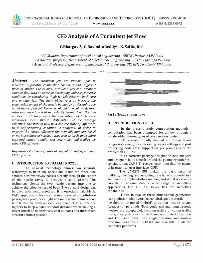
IV. NOZZLE GRID GENERATION WITH
DIFFERENT OUTLET CROSS SECTIONS
A structured grid was generated for 2D simulation
of flow around the nozzle model. The overall domain was
selected based on several iterations, boundary conditions
and finally a domain extending 5 times the major length of
the nozzle model. Total of 50,000 cells were used in the
grid system.
Fig 3. Nozzle Grid Generation With Square Cross Section
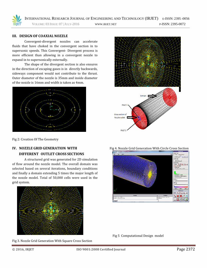
Fig 4. Nozzle Grid Generation With Circle Cross Section
Fig 5 Computational Design model
INTERNATIONAL RESEARCH JOURNAL OF ENGINEERING AND TECHNOLOGY (IRJET) E-ISSN: 2395 -0056
VOLUME: 03 ISSUE: 07 | JULY-2016 WWW.IRJET.NET P-ISSN: 2395-0072
© 2016, IRJET ISO 9001:2008 Certified Journal Page 2373
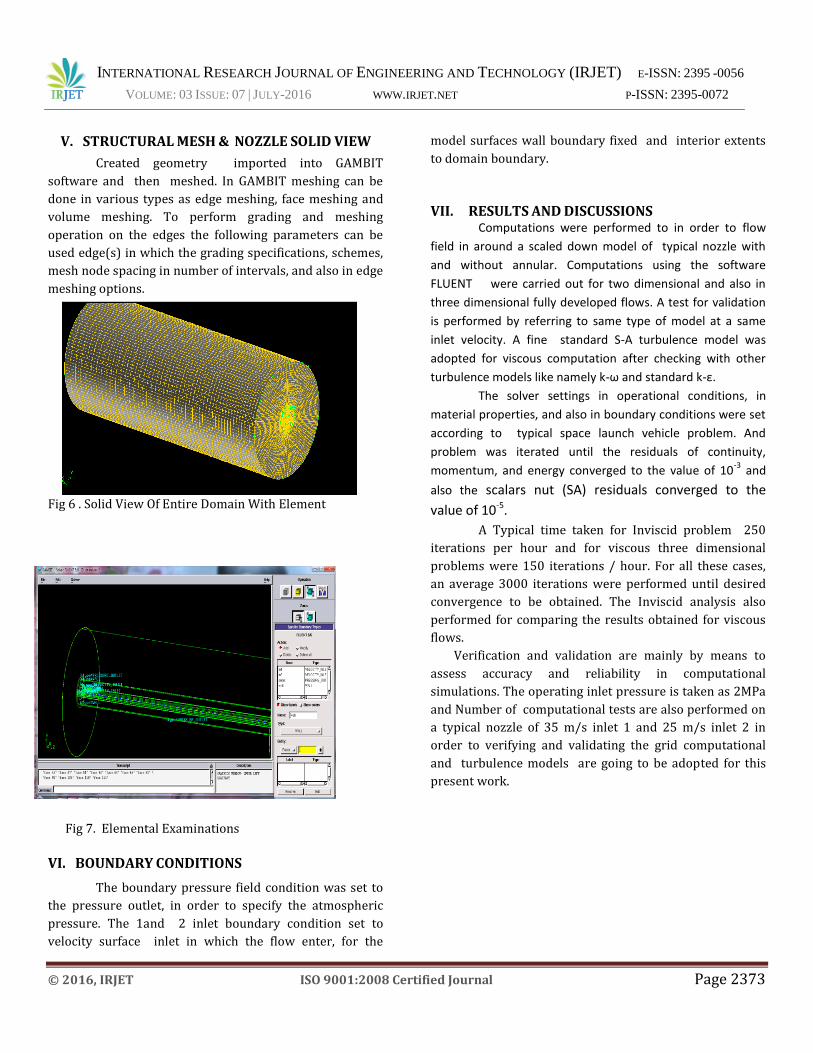
V. STRUCTURAL MESH & NOZZLE SOLID VIEW
Created geometry imported into GAMBIT
software and then meshed. In GAMBIT meshing can be
done in various types as edge meshing, face meshing and
volume meshing. To perform grading and meshing
operation on the edges the following parameters can be
used edge(s) in which the grading specifications, schemes,
mesh node spacing in number of intervals, and also in edge
meshing options.
Fig 6 . Solid View Of Entire Domain With Element
Fig 7. Elemental Examinations
VI. BOUNDARY CONDITIONS
The boundary pressure field condition was set to
the pressure outlet, in order to specify the atmospheric
pressure. The 1and 2 inlet boundary condition set to
velocity surface inlet in which the flow enter, for the
model surfaces wall boundary fixed and interior extents
to domain boundary.
VII. RESULTS AND DISCUSSIONS Computations were performed to in order to flow
field in around a scaled down model of typical nozzle with
and without annular. Computations using the software
FLUENT were carried out for two dimensional and also in
three dimensional fully developed flows. A test for validation
is performed by referring to same type of model at a same
inlet velocity. A fine standard S-A turbulence model was
adopted for viscous computation after checking with other
turbulence models like namely k-ω and standard k-ε.
The solver settings in operational conditions, in
material properties, and also in boundary conditions were set
according to typical space launch vehicle problem. And
problem was iterated until the residuals of continuity,
momentum, and energy converged to the value of 10-3
and
also the scalars nut (SA) residuals converged to the
value of 10-5.
A Typical time taken for Inviscid problem 250
iterations per hour and for viscous three dimensional
problems were 150 iterations / hour. For all these cases,
an average 3000 iterations were performed until desired
convergence to be obtained. The Inviscid analysis also
performed for comparing the results obtained for viscous
flows.
Verification and validation are mainly by means to
assess accuracy and reliability in computational
simulations. The operating inlet pressure is taken as 2MPa
and Number of computational tests are also performed on
a typical nozzle of 35 m/s inlet 1 and 25 m/s inlet 2 in
order to verifying and validating the grid computational
and turbulence models are going to be adopted for this
present work.
INTERNATIONAL RESEARCH JOURNAL OF ENGINEERING AND TECHNOLOGY (IRJET) E-ISSN: 2395 -0056
VOLUME: 03 ISSUE: 07 | JULY-2016 WWW.IRJET.NET P-ISSN: 2395-0072
© 2016, IRJET ISO 9001:2008 Certified Journal Page 2374
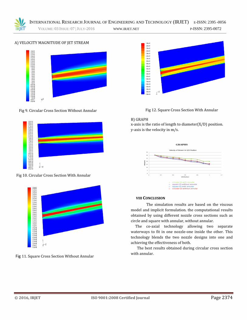
A) VELOCITY MAGNITUDE OF JET STREAM
Fig 9. Circular Cross Section Without Annular
Fig 10. Circular Cross Section With Annular
Fig 11. Square Cross Section Without Annular
Fig 12. Square Cross Section With Annular
B) GRAPH x-axis is the ratio of length to diameter(X/D) position.
y-axis is the velocity in m/s.
GRAPHS
0
5
10
15
20
25
30
35
0 0.2 0.4 0.6 0.8 1 1.2
Velo
city m
/s
X/D (Position )
Velocity of Stream Vs X/D Position
o circular CS with annularo square CS without annularo square CS with annularo circular CS without annular
VIII CONCLUSION
The simulation results are based on the viscous
model and implicit formulation. the computational results
obtained by using different nozzle cross sections such as
circle and square with annular, without annular.
The co-axial technology allowing two separate
waterways to fit in one nozzle-one inside the other. This
technology blends the two nozzle designs into one and
achieving the effectiveness of both.
The best results obtained during circular cross section
with annular.
INTERNATIONAL RESEARCH JOURNAL OF ENGINEERING AND TECHNOLOGY (IRJET) E-ISSN: 2395 -0056
VOLUME: 03 ISSUE: 07 | JULY-2016 WWW.IRJET.NET P-ISSN: 2395-0072
© 2016, IRJET ISO 9001:2008 Certified Journal Page 2375
IX REFERENCES
[1] TAKAHIRO KIWATA, TAICHIUSUZAWA“ Flow
Visualization & Characteristics Of A Co Axial Jet With
A Tabbed Annular Nozzle ˮ.
[2] TAKAHIRO KIWATA ,SHIGEOKIMURA “Flow Structure
Of A Coaxial Circular Jet With Axisymmetric & Helical
Instability Modes”.
[3] SEUNG TAEKOH,SETSURO HIRAOKO,YUTAKA
TADA”Heat Transfer Inlet Mixing Vessel With Rotating
Nozzle Around The Vessel Axis.”
[4] KOICHI TSUJIMOTO, KOJIAO,TOSHIHIKO SHAKOUCHI
& TOSHITAKE ANDO “Numerical Investigation Of Flow
Structures & Mixing Performances Of Vector -
Controlled Free Jet Using DNS”.
[5] YUMIKO OTOBE SHIGERUMATSUO, MASANORI
TANAKA,HIDEDO KASHIMURA”Astudy On
Characteristics Of Under Expanded Condensing Jet”.
[6] T.J.CHUNG, ”A Text book of Fluid dynamics” Cambridge
university press.
[7] JOHN ANDERSON, “Computational Fluid dynamics"
[8] H VERSTEG ,W .MALALASEKERA, "An Introduction to
Computational Fluid Dynamics: The Finite Volume
Method" Pearson pretence hall.