Embed Size (px)
Citation preview
" 1951- 58CESSNA CSSna
ON YOUR TRAVELS, STOP AT CESSNA
SERVlCE STATIONS FOR FAST,
EFFICIENT, ECONOMICAL SERVICE.
&£2d
CESSNA AIRCRAFT COMPANY WICHITA, KANSAS
Owner o Manual
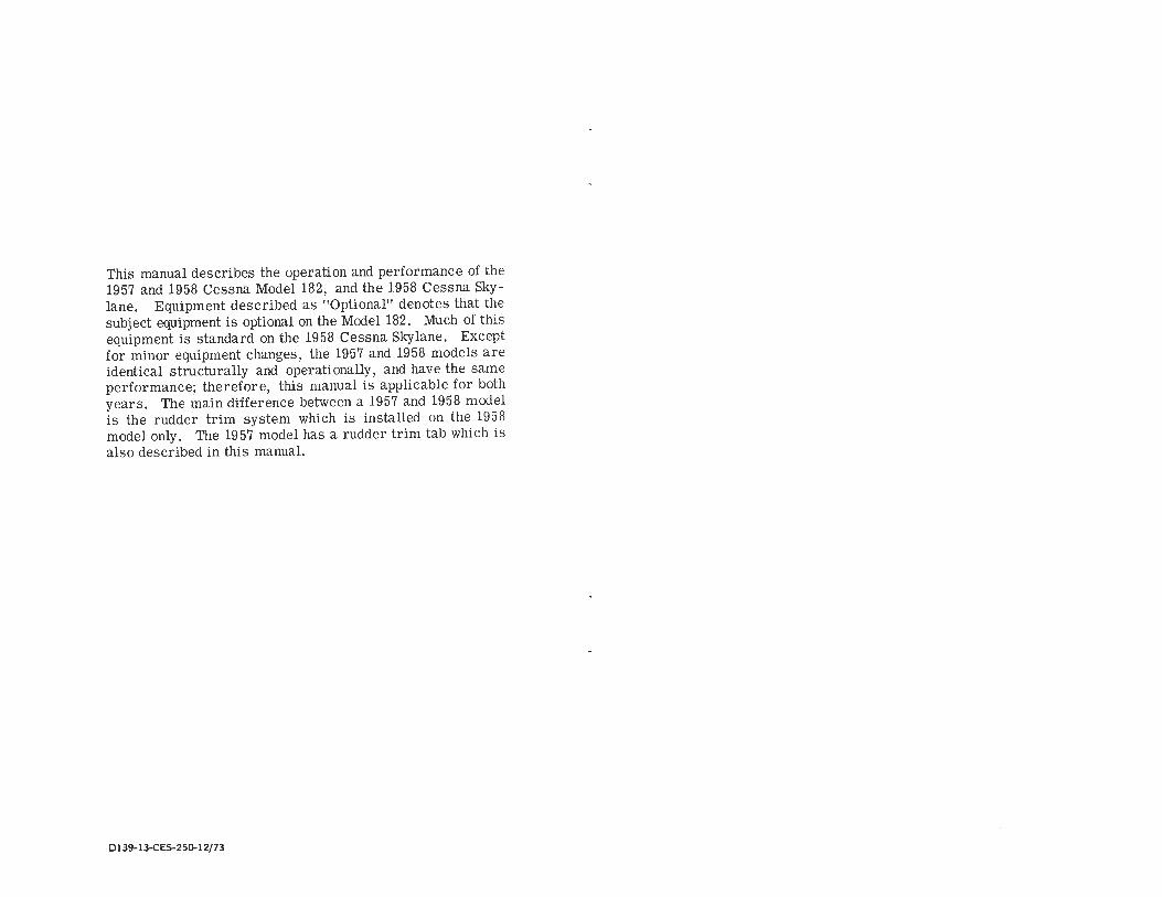
This manual describes the operation and performance of the1957 and 1958 Cessna Model 182, and the 1958 Cessna Sky-lane. Equipment described as "Optional" denotes that thesubject equipment is optional on the Model 182. Much of thisequipment is standard on the 1958 Cessna Skylane. Exceptfor minor equipment changes, the 1957 and 1958 models areidentical structurally and operationally, and have the sameperformance; therefore, this manual is applícable for bothyears. The main difference between a 1957 and 1958 modelis the rudder trim system which is installed on the 1958model only. The 1957 model has a rudder trim tab which isalso described in this manual.
D139-13-CES-250-12/73
Ûongraf uÎahons. . .
- You are now the owner of a truly outstand-
ing airplane. Your Cessna has been engineered togive you the ultimate in performance, styling,durability, flying comfort, and economy for bothbusiness and pleasure.- We share your pride as a Cessna owner andhave prepared this Owner's Manual as a guideto acquaint you with your airplane and its fineconstruction, equipment, ease of operation andits care.- Every fine possession is worth caring for,and this is especially true of your Cessna. Thisbook is dedicated to help you operate your air-
plane to get the utmost flying enjoyment andservice with a minimum of care.
i
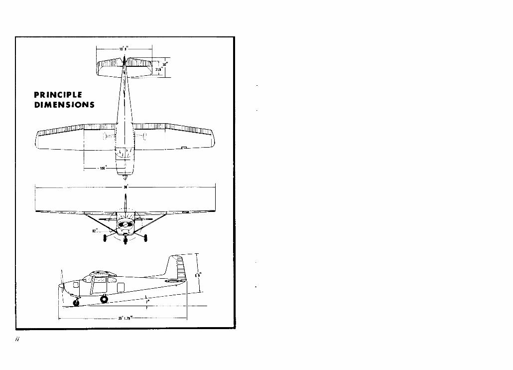
PRINClPLEDlMENSIONS
Illllli I
82 - - /
25' L75"
ii
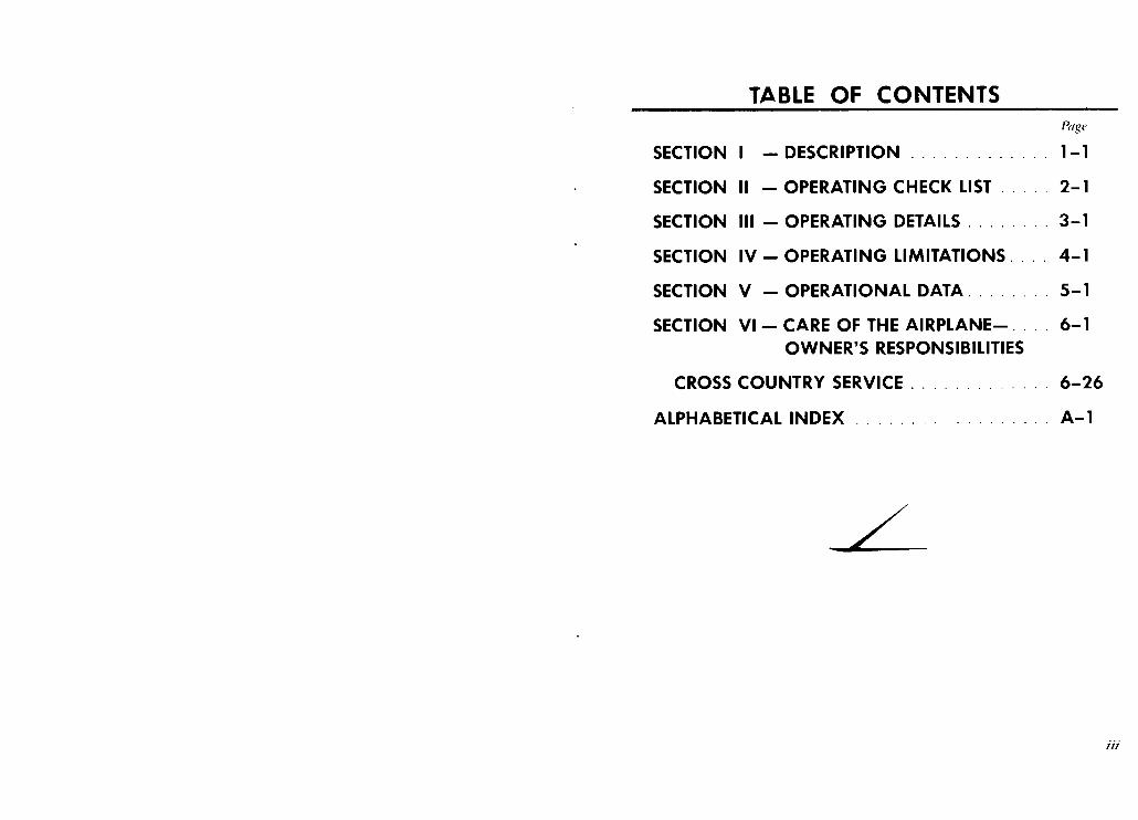
TABLE OF CONTENTSPage
SECTION I - DESCRIPTION . .
1-1
SECTION II - OPERATING CHECK LIST 2-1
SECTION III - OPERATING DETAILS 3-1
SECTION IV - OPERATING LIMITATIONS 4-1
SECTION V - OPERATIONAL DATA 5-1
SECTION VI - CARE OF THE AIRPLANE- 6-1OWNER'S RESPONSIBILITIES
CROSS COUNTRY SERVICE 6-26
ALPHABETICAL INDEX A-1
iii
12
34
56
78
910
1112
1314
1516
1718
1928
3029
2421
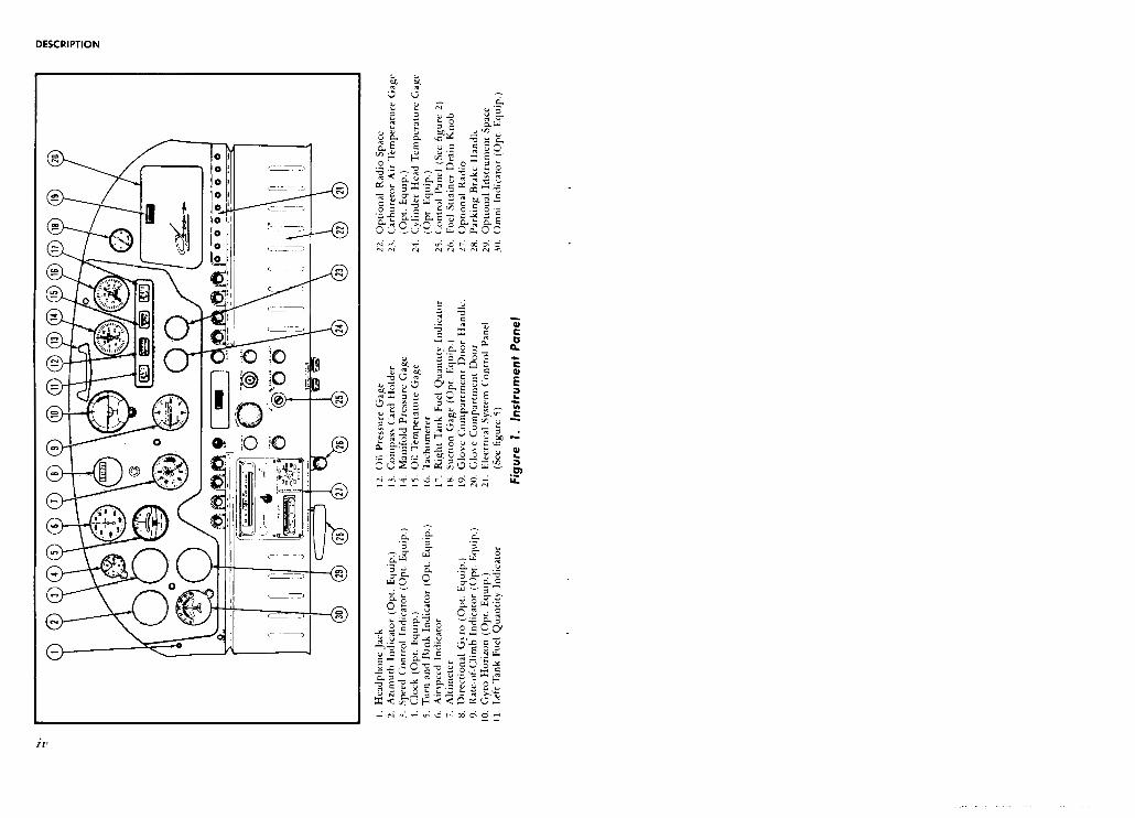
1.H
eadp
hone
jack
12.
Oil
Pres
sure
Gag
e22
.O
ptio
nal
Rad
ioSp
ace
2.A
zim
uth
Indi
cato
r(O
pt.
Equi
p)
13.
Com
pass
Car
dH
olde
r25
.C
arbu
reto
rA
irTe
mpe
ratu
reG
age
3.Sp
eed
Con
trol
Indi
cato
r(O
pt.
Equi
p.)
14.
Man
ifold
Pres
sure
Gag
e(O
pt.
Equi
p.)
4.C
lock
(Opt
.Eq
uip.
)15
.O
ilTe
mpe
ratu
reG
age
24.
Cyl
inde
rH
ead
Tem
pera
ture
Gag
e5.
Turn
and
Ban
kIn
dica
tor
(Opt
.Eq
uip.
)16
.Ta
chom
eter
(Opt
.Eq
uip.
)6.
Airs
peed
Indi
cato
r17
.R
ight
Tank
Fuel
Qua
ntity
Indi
cato
r25
.C
ontro
lPa
nel
(See
6gur
e2)
7.A
ltim
eter
18.
Suct
ion
Gag
e(O
pt.
Equi
p.)
26.
Fuel
Stra
iner
Dra
inK
nob
8.D
irect
iona
lG
yro
(Opt
.Eq
uip.
)19
.G
love
Com
partm
ent
Doo
rH
andl
e.27
.O
ptio
nal
Rad
io9.
Rat
e-of
-Clim
bIn
dica
tor
(Opt
.Eq
uip.
)20
.G
love
Com
partm
ent
Doo
r28
.Pa
rkin
gB
rake
Han
dle
10.
Gyr
oH
oriz
on(O
pt.
Equi
p.)
21.
Elec
trica
lSy
stem
Con
trol
Pane
l29
.O
ptio
nal
Inst
rum
ent
Spac
e11
.Le
ftTa
nkFu
elQ
uant
ityIn
dica
tor
(See
ngur
e 5)
30.
Om
niIn
dica
tor
(Opt
.Eq
uip.
)
Figu
re1.
Inst
rum
ent
Pane
l

description
ONE OF THE FIRST STEPS in obtaining the utmost performance,service, and flying enjoyment from your Cessna is to familiarizeyourself with your airplane's equipment, systems, and controls. Thissection will tell you where each item is located, how it operates andits function.
ENGINE FRICTION LOCKNUTA six-cylinder, Continental Model
0-470-L, 230 horsepower engine pow-ers your airplane. Compact, depend-able and efficient, the engine incorpo-rates hydraulic valve-lifters whichsilence valve operation. Built by acompany whose name has become abyword for precision-built, perform-ance-packed aircraft engines, the Con-tinental 230 horsepower engine meanstop performance for your airplane atlow maintenance cost. THROTTLE CONTROL
THROTTLE.The throttle (3, figure 2) is cen- NOTE
trally located on the lower half of the Because of the constant speedinstrument panel and is easily identi- propeller mechanism, standardfled by its large, round knob. Engine equipment on the airplane,power can be increased by pushing advancing the throttle will notthe throttle in toward the instrument increase engine rpm. It willpanel or decreased by pulling the con. increase the manifold pressure.trol out. To prevent the throttle from With each power increase, thecreeping, a knurled, friction-type, lock constant speed propeller auto-
nut is incorporated on the control to matically takes a larger "bite",secure it at any desired setting. enabling the engine to run at
I-1
DESCRIPTION
a constant speed at all times. figure 2) is located to the left of theEngine rpm can be changed by throttle. The push-pull control operatesadjusting the propeller control. the carburetor air intake butterflyRefer to "PROPELLER PITCH valve which proportions the hot andCONTROL" paragraph on cold air entering the carburetor. Pull-page 1-5 for this procedure. ing the control out provides heated air
for the carburetor while pushing thecontrol all the way in provides onlycold air for the carburetor.
LOCKING LEVER The controL has a center buttonlocking device. To move the control.press the lock button in with thethumb and hold while moving thecontrol to the desired position. Lockthe control by releasing the thumb
MIXTURE CONTROL pressure on the button.Air pulled into the heater muffs
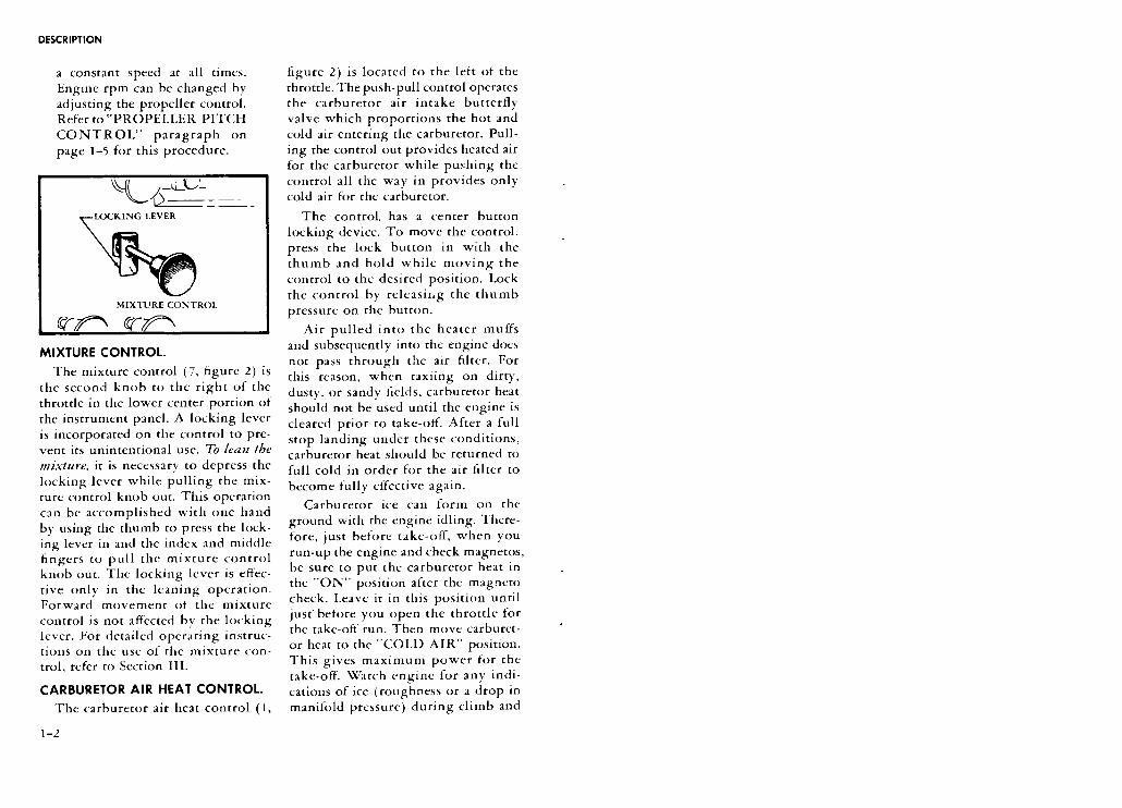
MIXTURE CONTROL. and subsequently into the engine doesnot pass through the air filter. For
The mixture control (7, figure 2) is ·
this reason, when taxiing on dirty,the second knob to the right of the dusty, or sandy fields, carburetor heatthrottle in the lower center portion of should not be used until the engine isthe instrument panel. A locking lever cleared prior to take-off. After a fullis incorporated on the control to pre-
stop landing under these conditions,vent its unintentional use. To lean the carburetor heat should be returned tomixture, it is necessary to depress the full cold in order for the air filter tolocking lever while pulling the mix- become fully effective again.ture control knob out. This operation
Carburetor ice can form on thecan be accomplished with one hand. . .
by using the thumb to press the lock- ground with the engine idling. There-. - fore, just before take-off, when youing lever in and the index and middle
fingers to pull the mixture control run-up the engine and check magnetos,
knob out. The locking lever is effec- be sure to put the carburetor heat in
tive only in the leaning operation. the "ON" position after the magneto
Forward movement of the mixture check. Leave it in this position until
control is not affected by the locking just before you open the throttle for
lever. For detailed operating instruc the take-off run. Then move carburet-
or heat to the "COLD AIR" osition.tions on the use of the mixture con- Ptrol, refer to Section III. This gives maximum power for the
take-off. Watch engine for any indi-CARBURETOR AIR HEAT CONTROL cations of ice (roughness or a drop in
The carburetor air heat control (1, manifold pressure) during climb and
1-2
DESCRIPTIONALPHABETICALINDEX
Right Tank Fuel Quantity indicator, iv Take-Off, 2-3, 3-2, 3-45 7Rudder Control System, 6-10, 6-11 crosswind, 2-3
Ruger Pedals, 1-13, 1-14 diagram, 5-2Rudder Tab, 6-12 minimum run, 2-3Rudder Trim Control Wheel, 1-14 normal, 2-3
obstacle clearance, 2-3 'EM
soft or rough field, 2-3k -O an3d3-ClimbChart, 5-3
S Throttle, 1-1, 1-3Tie-Down Procedure, 5-8Tires, 6-2
m mpener, 6-3 TupressurLnk3Indicator,
iv, 1-17Speed Control Indicator, ivStabilizer Control System, 6-12, 6-13Stall Warning Indicator, 1-17Stall Warning Transmitter Heater, 1-17Staalling3-7peeds Chart, 3-7
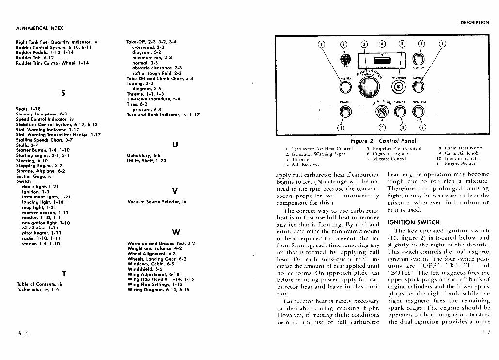
U Figure 2. controlPanetStarter Button, 1-4, 1-10 I Carburetor Air Heat Control 5. Propeller Pitch Control 8. Cabin Heat KnobStarting Engine, 2-1, 3-1 Upholstery, 6-6 2. Generator Warning Light 6. Cigarette Lighter 9. Cabin Air KnobSteering, 6-10 Utility Shelf, 1-23 3. Throttle 7. Mixture Control 10. Ignition SwitchStopping Engine, 3-3 4. Ash Receiver i1. Engine PrimerStorage, Airplane, 6-2Suction Gage, iv apply full carburetor heat if carburetor heat, engine oper2tion may becomeSwitch, begins to ice. (No change will be no- rough due to too rich a mixture.
dome light, 1-21-
ignition, 1-3 ticed in the rpm because the constant Therefore, for prolonged cruisinginstrument lights, 1-21 speed propeller will automatically night,it may be necessary to lean theInnding light, 1-10 Vacuum Source Selector, iv compensate for this.) mixture whenever full carburetormap light, 1-21marker beacon, 1-11 The correct way to use carburetor heat is used.master, 1-10, 1-11 heat is to first use full heat to remove
v tn light, 1-10any ice that is forming. By trial and IGNITION SWITCH.
pitot heater, 1-11 W error, determine the minimum amount The key-operated ignition switchradio, 1-10, 1-11 of heat required to prevent the ice (10, figure 2) is located below andstarter, 1-4, 1-10 WWgmht nadnd Ground Te2st,2-2 from forming; each time removing any slightly to the right of the throttle.
Wheel Alignment, 6-3 ice that is formed by applying full This switch controls the dual-magnetoWheels, Landing Gear, 6-2 heat. On each subsequent trial, in- ignition system. The four switch posi-
habi5n, 6-5
crease the amount of heat applied until tions are "OFF","
R", "L andT Wing Adjustment, 6-18 no ice forms. On approach glide just "BOTH". The left magneto Sres the
Wing Flap Handle, 1-14, 1-15 before reducing power, apply full car- upper spark plugs on the left bank ofTable of Contents, m Wing Flap Settings, 1-15 -
Tachometer, iv, 1-4 Wiring Diagram, 6-14, 6-15 buretor heat and leave in this posi- engine cylinders and the lower sparktion. plugs on the right bank while the
Carburetor heat is rarely necessary right magneto fires the remainingor desirable during cruising night. spark plugs. The engine should beHowever, if cruising nightconditions operated on both magnetos, becausedemand the use of full carburetor the dual ignition provides a more
DESCRIPTION ALPHABETICALINDEX
complete burning of the fuel-air mix- that the engine be turned over L Oture driving the pistons. The "R" and while priming. It may be nec-
Landing, 2-5, 3-7 Oil Dilution System, 3-9L" positions are used for checking essary to continue priming crosswind, 2.5 switch, 1-11
purposes only. until the engine runs smoothly. diagram, 5.6 Oil Filler Cap, 1-6normal, 2-5 Oli Level, 1-6
ENGINE PRIMER. STARTERBUTTON. short field, 2-5 Oil Pressure Gage, iv, 1-8Landing Gear, 1-15, 6-2 Oil Specification and Grade, 1-8
The engine primer (11, figure 2) is A push-button switch (1, figure 5) Landing Lights, 1-20 Oil System, 1-6a manual pump type and is located operates the electrical starter motor Left Tank Fuel Quantity Indicator, iv schematic, 1-7
below and slightly to the left of the . . .
Let-down, 2-4, 3-3 Oil Temperature Gage, iv, 1-8.
and is located at the left side of the in- Lifting and Jacking, 6-2 Omm Indicator, ivthrottle. Regardless of the outside air Light Operations Authorized, 4-1temperature, use of the primer is nor- strument panel dome, i-2i optionalRadio space, iv
mally required for starting the engine. TACHOMETER. (*|* or ning, 1-io, 1-13 OxcyÃdSys m, 3-9
The primer aids starting by supplying A recording engine tachometer (16, landing, 1-2o diagram, a-ilan initial charge of raw fuel to the figure 1) is mounted above the en- map, 1-21 duration chart, 3-12
navigation, 1-20 face mask, 3-14engine cylinders- gine instrument cluster on the right radio dial, 1-21 flow indicator, 3-14
NOTE side of the instrument panel. The Lighting Eguipment, 1-20 operation, 3-10
Only five cylinders are primed tachometer indicates engine RPM and a ra¢cesna 182, i-2a
9pru scoangnc couplings, a-i2
by the engine primer. The right records engine operating hours. Lower Forward Section of Cabin, 1-14 regulator, 3-11
rear cylinder (No. 1) provides MANIFOLD PRESSUREGAGE.Lubricartion, b167 schematic, 3-13
the manifold pressure source A manifold pressure gage (14, fig-connection and is not primed. . . .
ure 1) is mounted immediately to theTo operate the primer, proceed as left of the tachometer and above thefollows: engine instrument cluster on the right M
(1) First, unlock the plunger by side of the instrument panel. This in- Parking Brake Handle, iv, 1-16turning the knob counter- strument indicates the pressure of the Magnetic Compass, 1-18 Parking Brake Operation, 1-16
- Main Landing Gear, 1-15 Pitot Heater, 1-17clockwise until the knob pops fuel-air mixture entering the engine Maneuvers, Pitot - Static System, 1-17part way out- cylinders and is calibrated in inches normal category, 4-1 Pressure, Tire, 6-3
(2) Slowly pull the plunger all of mercury. By observing the manifold Manifold Pressure Gage, iv, 1-4 Primer, Engine, 1-3, 1-4Map Light, 1-21 Principle Dimensions, nthe way out and then push the pressure gage and adjusting the pro- Map Pocket, 1-23 Propeller, 1-5, 6-7
plunger all the way in. This peller and throttle controls, the power Marker Beacon Switch, 1-11 Propeller Pitch Control, 1-3, 1-5action is termed "one stroke out ut of the en ine can be adjusted to Master Switch, 1-10, 1-11
Miscellaneous Equipment, 1-22of the primer"- any power setting recommended in the Mixture controlKnob, 1-2, 1-3
(3) Normal weather will require operating procedures of Section II or Mooring Your Airplane, 6-1
one or two strokes of the performance charts of Section V.primer, and very cold (-20° F)weather may require three or CYLINDER HEAD TEMPERATURE Radio Dial Light, 1-21four strokes. GAGE. (OPTIONAL EQUIPMENT.) Radio Switch, 1-10, 1-11
(4) Normally, the engine is start- A cylinder head temperature gage N ns.c ,b 5a
ed immediately after the prim- (24, figure 1) is mounted immediately Navigation Lights, 1-20 Rear Seat, 1-18ing operation. In very cold below the engine instrument cluster on nasher, 1-20 Rheostat, Instrument Lights, 1-21
weather it is recommended the right side of the instrument panel. Nose Gear, 1-15 Rheostat, Radio Dial Light, 1-21
A-31-4
ALPHABETICALINDEX DESCRIPTION
E Gyro Horizon, iv The gage is calibrated in degrees stant speed feature enables your en-Ground Service Plug, 1-12, 6-14 Fahrenheit and is electrically operated. gine to deliver uniform horsepower
Electrical System, 1-11 However, its sole source of power is for each throttle setting.control panel, iv, 1-10, 1-11schematic, 1-12 a thermocouple mounted under the PROPELLERPITCH CONTROL.wiring diagram, 6-14, 6-15 lower spark plug of the left rear en The control knob (5, figure 2) toEle a r Control System, 6-12 H gine cylinder and thus the instrument the right of the throttle controls thebefore starting, 2-1, 3-1
Headphone Jack, ivrequires no power from the electrical engine speed. With the control full
comraa nnt
i6ons,4-2 Heating System, 1-18, 1-19 system. By observing the gage read- forward, the propeller is in high rpm
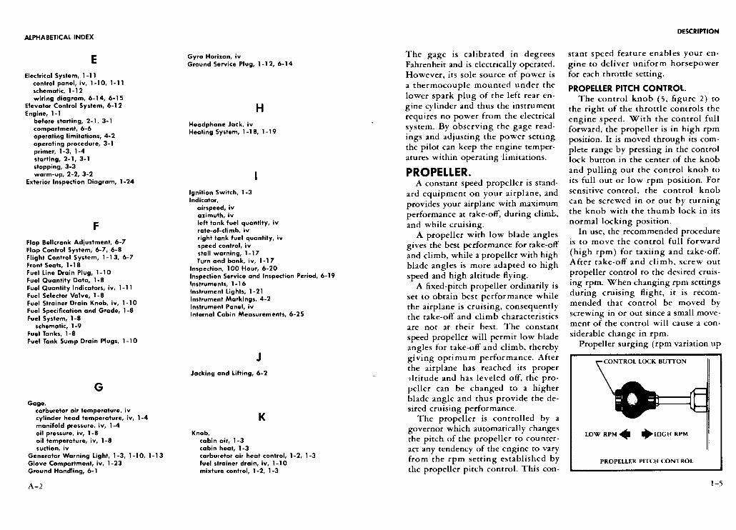
operating procedure, 3-1 ings and adjusting the power setting position. It is moved through its com-primer, 1-3, 1-4 the pilot can keep the engine temper- plete range by pressing in the controlstarting, 2-1, 3-1 atures within operating limitations lock button in the center of the knobstoppmg, 3-3warm-up, 2-2, 3-2 PROPELLER. and pulling out the control knob to
Exterior Inspection Diagram, 1-24 A constant speed propeller is stand. its full out or low rpm position. ForIgnition Switch, 1-3 ard equipment on your airplane, and sensitive control, the control knob
,at,°,ia,
¡, provides your airplane with maximum can be screwed in or out by turning
azimuth, iv performance at take-off, during climb, the knob with the thumb lock in its
F Ieft tank fuel quantity, iv and while cruising. normal locking position.
g a u I uantity, iv A propeller with low blade angles In use, the recommended procedureFlap BCel k Adjustment,6 speed control, iv gives the best performance for take-off is to move the control full forwardFlight Control System, 1-13, 6-7 stall warning, 1-17 and climb, while a propeller with high (high rpm) for taxiing and take-off.
Front Seats, 1-18Insp
n ann1 r,
270blade angles is more adapted to high After take-off and climb, screw out
FF neai
ta n u ,1-10
Inspection Service and inspection Period, 6-19 speed and high altitude flying. propeller control to the desired cruis-
Fuel Quantity Indicators, iv, 1-11 Instruments, 1-16 A fixed-pitch propeller ordinarily is ing rpm. When changing rpm settingsFuel Selector Valve, 1-8
'I t a n ,-2 set to obtain best performance while during cruising flight, it is recom-
SStreanat
a n dn ve 1-80Instrument Panel, iv the airplane is cruising, consequently mended that control be moved by
Fuel System, 1-8 Internal Cabin Measurements, 6-2sthe take-off and climb characteristics screwing in or out since a small move-
schematic, 1-9 are not at their best. The constant ment of the control will cause a con-el Taankk
Sump Drain Plugs, 1-lo speed propeller will permit low blade siderable change in rpm.
angles for take-off and climb, thereby Propeller surging (rpm variation up
.! giving optimum performance. AfterCONTROL LOCK BUTTON
Jacking and Lifting, 6-2 the airplane has reached its properaltitude and has leveled off, the pro-
G peller can be changed to a higherGage, blade angle and thus provide the de-
carburetor air temperature, iv sired cruising performance.cylinder head temperature, iv, 1-4 The propeller is controlled by amanifold pressure, iv, 1-4
.
oil pressure, iv, 1-8 Knob governor which automatically changes' LOW RPM HIGH RPMoil temperature, iv, 1-8 cabin air, 1-3 the pitch of the propeller to counter-suction, iv cabin heat, 1-3 act any tendency of the engine to varyGenerator Warning Light, 1-3, 1-10, 1-13 carburetor air heat control, 1-2, 1-3
Glove Compartment, iv, 1-23 fuel strainer drain, iv, 1-lo from the rpm setting established by PROPELLER PITCH CONTROLGround Handling, 6-1 mixture control, 1-2, 1-3 the propeller pitch control. This con-
A-2 I-5
DESCRIPTION
and down several times before engine opening the 2ccess door on the left ALPHABETICAL INDEXsmooths out and becomes steady) can side of the engine cowl and re2dingbe prevented by smooth throttle and the oil level on the dipstick, locatedpropeller control operation. Do not just aft of the left rear engine cylinder.change throttle and propeller controlset- The dip stick incorporates 2 spring cessnaService Publications, 6-26rings with jerky and rapid motions. lock which prevents it from working cigaretteLighter, 1-3, 1-22
loose in flight. The dip stick can be Adjustable Stabilizer Control Wheel, 1-13 Circuit Breakers, 1-11, 1-13NOTE removed by rotating it until the spring After Landing, 2-5 Check List, 2-1
If the engine power and rpm lock is disengaged and pulling the dip AAilo
rran de6
-6 9 Clea nnum surfaces, 6-5
are to be increased, increase the stick up and out. When replacing the Airplane File, 6-18 battery, 6-4
propeller control first and then dip stick, m2ke sure th2t the spring Airspeed Correction Table, 5-1 carburetor air filter, 6-6
the throttle. If power and rpm lock is engaged. AArspeeddLn
taa'tns 4-1
enDgine compartment, 6-6
are to be decreased, reduce the To obtain correct oil level readings, Altimeter, iv tires, 6-3
throttle first and then the pro- it is import2nt that the engine be shut Aluminum Surfaces, 6-5 upholstery, 6-6
peller control. In this manner, down at least 5 to 10 minutes prior to g¡, Sce ers, 1-3, 1-23dh d
65-5
excessive cylinder pressures the oil check. This permits the engine Assist straps,1-22 clearingthe Propeller, 3-1
will be avoided. oil to drain out of the engine oil pas- Azimuth Indicator, iv Climkb, 2-4 -62, 3-4
s2ges into the oil sump giving a more coat Hanger Hook, 1-23
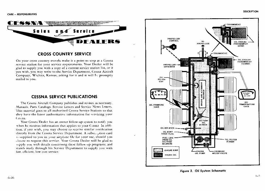
OIL SYSTEM. 2ccur2te oil level reading. Cold Weather Operation, 3-8Compass Card Holder, iv
The Continental 0-470-L engine has NOTE control,a wet sump oil system which utilizes Oil should be 2dded if below ad ta rle stabilizer, 1-13
the engine pan as an oil tank. Other nine quarts and should be full saggage compartment,1-23 cabin heater, 1-3major components of the system are if an extended flight is planned. Battery, 6-4 carburetar air heat, 1-2, 1-3
an engine-driven oil pump 2nd an oil . . . Befav Entering Airplane, 2-1 mixture, 1-2, 1-3- The oil filler cap is made accessible Before Landin 2-4 panel, 1-3
cooler mtegrally mounted on the en- s' rk brakby opening the access door on the Befo;e startingEngine, 2-1, 3-1 pa ing e, ivgin
1 temperature is regulated auto- top of the engine cowl. In repl2cing Bef te ke-Off, 2-3 propdell pitc1h, 14-3
. . the oil filler cap, make sure that it is Brake Pedais, 1-16 wheels, 1-13matically in this system by a thermo-
on firmly and turned clockwise 2s far Brake System, 1-16 Cross Country Service, 6-26statically controlled oil cooler. The Cruise, 3-2, 3-6
as it will go to prevent loss of oil thru Cruisin ,2-4thermostat shuts off the passage of oil 9
. the filler neck. cylinderHead Temperature Gage, iv, 1-4through the cooler whenever the oiltemperatures are below 150° F. Ordi- OIL SPECIFICATION AND GRADE.narily, the oil cooler is adequate to Aviation grade oil is recommended
keep oil temperatures well within the for your airplane and should beCabin Air Knob, 1-3
normal operating range as indicated changed every 25 hours of oper2tion cabinAir Temperature Control System, 1-18 Dby the green arc on the oil tempera. When adding or changing oil, use the diagram, 1-19
ture indicator. gr2des in the following table: cabinDoors, 1-22 Dip Stick, 1-6Cabin Heat Knob, 1-3 Directional Gyro, iv
OIL LEVEL. Average Outside Recommended cabinVentilators, 1-20 Dome Light, 1-21
The oil c2pacity of the Continent21 Temperature OH Grader Hec
2Cool, 1-2, 1-3
Drain Plu,sump,
1-100-470-L engine is twelve quarts. The Below 40° F. SAE 30 carburetorAir Temperature Gage, iv fuel line, 1-10
quantity can be checked e2sily by Above 40° F. SAE 50 centerof Gravity Envelope, 4-3 oil sump, 1-7
1-6 A--I
CARE - RESPONSIBILITIES DESCRIPTION
THERMOSTAT
Sales a SeruitePROPELLER
CONTROL .OIL COOLER
PHOPELLER (THERMOSTATOPEN)
CROSS COUNTRY SERVICE '*, THERMOSTAT
On your cross country travels make it a point to stop at a Cessna *- °1HLEC
service station for your service requirements. Your Dealer will be PROPELLER CLOSED)
glad to supply you with a copy of a current service station list, or if GOVERNOR
you wish, you may write to the Service Department, Cessna AircraftCompany, Wichita, Kansas, asking for it and it will be promptlymailed to you. °'LLE
CAP
CESSNA SERVICE PUBLICATIONSI a
The Cessna Aircraft Company publishes and revises, as necessarv. 1. O OILOIL PRESSURE TEMPERATURE
Manuals, Parts Catalogs, Service Letters and Service News LetterS. GAGE GAGE
This material goes to all authorized Cessna Service Stations so thatthey have the latest authoritative information for servicing yourCessna.
Your Cessna Dealer has an owner follow-up system to notify you sue on
when he receives information that applies to your Cessna. In addi SCREEN
- - - OIL DIP STICKtion. if you wish, you may choose to receive similar not16cationdirectly from the Cessna Service Department. A subscation card DR
LINUG
is supplied to you in your airplane file for your use, should you FUEL LINE
eboose to request this service. Your Cessna Dealer will be glad to ',"°uMOOINL OISLCRFIELENER
wpply you with details concerning these follow-up programs, and SOLENOID
stands ready through his Service Department to supply you withfast, efficient, low cost service.
ENGINE SUMP ENGINE PRESSURE
- OIL PUMP RELIEF VALVEENGINE OIL
Figure 3. Oil System Schematic6-26 1--7
DESCRIPTION CARE - RESPONSIBILITIES
NOTE ing air by a filter screen located in the
During oil changes, remove and air scoop. Proper cleaning and servic-
clean oil filter screen located ing of this air filter is important to Cabin (floor) Lengths:. . . increase life and maintain top efTi- ynow to NOTE
on the right side of the engine. Measurements are with
accessory section. ciency of the engine. The filter should . . . . . - 43 in co-pilot seat, rear seat,be serviced every 25 hours (during
- - - 21 inand baggage compartment
OIL TEMPERATURE GAGE- regular oil change) or oftener whenmh o
ablA capillary type, oil temperature operating in dusty conditions. Under 27 in- and saving 40 lbs on emp-
gage (15, figure 1) is mounted within extremely dusty conditions, dailythe engine instrument cluster on the maintenance of the air filter is recom-
right side of the instrument panel. A mended. Refer to the servicing in-green arc on the gage dial indicates structions stamped on the carburetor 'the normal operating range of oil air filter for the servicing proceduretemperatures. Refer to Section IV for to be used.instrument markings.
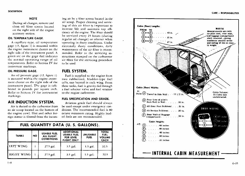
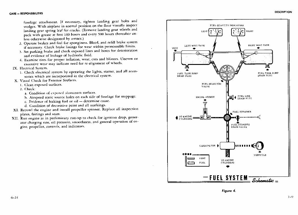
OIL PRESSURE GAGE. FUELSYSTEM.An oil pressure gage (12, figure 1) Fuel is supplied to the engine from
is mounted within the engine instru- two rubberized, bladder-type fuelment cluster on the right side of the cells, one located in each wing. Frominstrument panel. The gage is cali- these tanks, fuel is gravity-fed through cabin(floor) Widths:brated in pounds per square inch. a fuel selector valve and fuel strainerRefer to Section IV for instrument to the engine carburetor. (i) / Cabin Volume:
.
Point Tunnel to Side Wall .. - 15 1/2 in. 55 Cubic feet
markmgs unobstructed.FUELSPECIFICATION AND GRADE• Rear Line of pilot's
AIR INDUCTION SYSTEM. Aviation grade fuel should always Seat-Wall to Wall. . . . . .36 tn.
Air is ducted to the carburetor from be used except under emergency con- (Ï)^ft Door Post Bulkhead . . . 31 in.
an air scoop located on the bottom of ditions. The recommended fuel is 80 (i) Aft Section Bulkhead . . . . .30 in.D0 0 R WI DI HS
the engine cowl. Dirt and other for- octane minimum rating. Highly lead- (i) Rear wan-or saggageeign matter is filtered from the incom- ed fuels are not recommended. Compartment - -
30 in.
Cabin Heights: 40 36 nwho
FUEL QUANTITY DATA (U. S. GALLONS). ^2- - .48 inches i n uw)ws
. . . . . . 46 inches
ADDITIONAL TOTAL - - 45 inches
TANKS NOUASLALFLLEFUHEL UFSOARBLLEELEL UNFUUSEABLE
V ME . . . . . 40 inchesCONDITIONS FLIGHTONLY EACH . . . . . - 21 inches
LEFT WING l 27.5 gal. 3.5 gal. 1.5 gal. 32.5
RIGHT WING 1 27.5 gal. 3.5 gal. 1.5 gal. 32.5--- INTERNALCABINMEASUREMENT
1-86-25
CARE - RESPONSIBILITIES DESCRIPTION
fuselage attachment. If necessary, tighten landing gear bolts and
wedges. With airplane in normal position on the floor visually inspect FUEL QUANTITY INDICATORS
landing gear spring leaf for cracks. (Remove landing gear wheels andpack with grease at first 100 hours and every 500 hours thereafter un- LEFT RIGHT
less otherwise designated by owner.)2. Operate brakes and feel for sponginess. Bleed, and refill brake system
if necessary. Check brake linings for wear within permisssible limitS. LEFT WING TANK RIGHT WING TANK
3. Set parking brake and check exposed lines and hoses for deteriorationand evidence of leakage of hydraulic fluid.
4. Examine tires for proper inflation, wear, cuts and blisters. Uneven orexcessive wear may indicate need for re-alignment of wheels.
IX. Electrical System.1. Check electrical system by operating the lights, starter, and all acces-
sories which are incorporated in the electrical system. SUMP TA SUMP
X. Visual Check for Exterior Surfaces.1. Clean exposed surfaces FUEL SELECTOR
2. Check: VALVE
a. Condition of exposed aluminum surfaces.b, Airspeed static source holes on each side of fuselage for stoppage
ENGINE PRIMER FUEL LINE
c. Evidence of leaking fuel or oil - determine cause. DRAIN PLUG
d. Condition of decorative paint and all markings.XI. Recowl the engine and install propeller spinner. Replace all inspection
plates, fairings and seats. FUEL STRAINER
XII. Run engine as in preliminary run-up to check for ignition drop, gener- ÉcTO EN ES
ator charging rate, oil pressure, smoothness, and general operation of en-gine, propeller, controls, and indicatorS. FUEL STRAINER
DRAIN VALVE
CARBURETOR i ggggg i
co enTHROTTLE
VENTTO ENGINE
FUEL CYLINDERS
-FUEL SYSTEMgFigure 4.
6-24I-9

DESCRIPTION CARE - RESPONSIBILITIES
tion. Grease lube fittings. Pack wheel at 500 hours. Check steering1 2 3 4 5 arms for security. Check infl2tion of strut. Fill shimmy d2mpener.
:. Check rigging of steering. With rudder pedals in neutral, they should---- measure 6½ " from firew211 to the hingeline of the br2ke pedal. With
- Ly:y rudder pedals neutr21, nose wheel should be in neutral position with
. VII.Cabnon cctk inn steering rods.
1. Clean and check condition of:2. Plexiglas windshield 2nd windows.
I Starter Button 6. Generator Warning Light b. Upholstery - V2cuum if possible.2 Master Switch 3. Marker Beacon Switch3 Navigation Light Switch 8. Radio Switch c. Instrument glasses.4. l.anding Light Switch 9. Pitot Heat Switch d. Ash trays.5. Radio Switch 10. Oil Dilution Switch e. Metal cabin trim.
Figure 5. Electrical f. Instrument and control panels.FUEL SELECTOR VALVE. The knob provides a quick, conveni- g. Decals, control p2nel lettering, 2nd compass correction c2rd.
A rotary-type fuel selector valve is ent method of draining water and 2. Check operation and condition of:located between the front seats at the sediment that may have collected in 2. Door 12tches.aft end of the cabin floor tunnel. The the fuel strainer. The fuel strainer is b. Window opening mech2nism.
valve has four positions labeled located in the lower aft section of the c. Manifold heating system valves 2nd ducts."BOTH OFF", "LEFT TANK", engine compartment just forward of d. Control knobs. -
"BOTH ON", and "RIGHT TANK". the firewall. e. Safety belts.The "BOTH OFF" position shuts off A two ounce quantity of fuel (ap- f. Ventilating system.both fuel tanks from the fuel system proximately 3 to 4 seconds of drain g. Seat adjustment mechanism.
and allows no fuel to pass the fuel se. knob operation) should be drained h. Front seat stop cotter pins on seat rails.
Lector valve. The "LEFT TANK" or from the strainer before the initial 3. Check the primer for le2kage and security."RIGHT TANK" position allows flight of the day or after each refuel- 4. On rudder bar and control tee assemblies, check:fuel to flow from only one fuel tank ing operation to insure against the 2. Security of mounting.at a time, while "BOTH ON" per- presence of water or sediment in the b. Cable connection points.mits simultaneous flow from both fuel. The spring loaded drain valve c. Pulley installations.tanks. Important - The fuel valve in the strainer is OPEN when the fuel d. Rudder return springs.handle is the pointer for the fuel se- strainer drain knob is pulled out all 5. On battery, check:lector valve and indicates the setting the way. The drain valve automatically 2. Electrolyte level and specific gravity (1.310-1.226)
of the valve by its position above the closes when the knob is released b. Cables for security and condition.dial. Take-offshould be made in the
FUELTANK SUMP DRAIN PLUG. c. B2ttery security."BOTH ON" position to prevent inad- d. Cleanliness of battery box and terminals - clean off 2nd neutralizevertent take-offon an empty tank. A fuel tank sump dr2in plug is lo spilled fluid with soda water solution and rinse with clear water.
cated on the underside of each wing 6. Drain sediment and water from fuel line at plug loc2ted on the bellyFUEL STRAINER DRAIN KNOB· in line with the rear edge of the cabin of the airplane.
A fuel strainer drain knob decaled door and out a few inches from the
"STRAINER DRAIN" (26, figure fuselage. These plugs are used to drain VIII. Main Landing Gear and Brakes.1) is mounted slightly to the left of any sediment or water that may col. l. Holst or jack up airplane to remove weight from 12nding gear. Shakecenter below the instrument panel. lect in the fuel tanks. Under normal landing gear and wheels for any sign of looseness and visually inspect
6-251-10
CARE - RESPONSIBILITIES DESCRIPTION
3.>rckkanLoicbklsor a asi >nskas nedcessary.
7 10 (Ï3)(i4) (Ï5)4. Check jamb nut on blade travel-stops for tightness.5. Check piston and blade clamps for evidence of leakage.6. Chaeck prodpellelr t htnessakne shafe
they have not shifted. ' ''L
8. Grease propeller at grease fittings. -•- - -- --- --¯
--
""--'-•¯
9. Clean engine cowl and propeller spinner.IV. Wing Inspection.
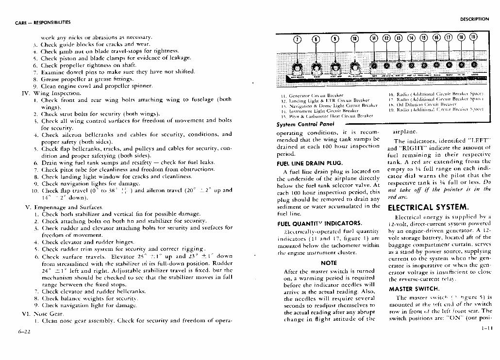
- 11. Generator Circuit Breaker 16. Radio (Additional Circuit Breaker Space)1. Check front and rear wing bolts attaching wing to fuselage (both t2. Landing Light & LTR Circuit Breaker D. Radio (Additional Circuit Breaker Space)
wings). 10 Navigation & Dome Light Circuit Breaker 18. Oil Dilution Circuit Breaker
2. Check strut bolts for security (both wings). 14, Instrument Light Circuit Breaker 19. Radio (Athlitional Circuit Breaker Space)- 15, Pitot & Carburetor Heat Circuit Breaker3. Check all wing control surfaces for freedom of movement and bolts
for security. System Control Panel4. Check aileron bellcranks and cables for security, conditions, and operating conditions, it is recom- airplane.
proper safety (both sides). mended that the wing tank sumps be The indicators, identified "LEFT"5. Check flap bellcranks, tracks, and pulleys and cables for security, con. drained at each too hour inspection and "RIGHT" indicate the amount of
dition and proper safetying (both sides). period fuel remaining in their respective
6. Drain wing fuel tank sumps and resafety - check for fuel leaks. FUEL LINE DRAIN PLUG. tank. A red arc extending from the
7. Check pitot tube for cleanliness and freedom from obstructions A fuel line drain plug is located on empty to ¼ full range on each indi-8. Check landing light window for cracks and cleanliness.
the underside of the airplane directly cator dial warns the pilot that the9. Check navigation lights for damage below the fuel tank selector valve. At respective tank is ¼ full or less. Do
10. Check flapdtravel (0 to 38 e ) and aileron travel (20° 2 up and each 100 hour inspection period, this rnot take off if the pointer is in the
plug should be removed to drain any an.
V. Empennage and Surfaces. sediment or water accumulated in the ELECTRICALSYSTEM.1. Check both stabihzer and vertical fin for possible damage. fuel line.2. Check attaching bolts on both fin and stabilizer for security. Electrical energy is supplied by a
3. Check rudder and elevator attaching bolts for security and surfaces for FUEL QUANTIT" INDICATORS- t2-volt, direct-current system poweredfreedom of movement. Electrically-operated fuel quantity by an engine-driven generator. A L2-
4. Check elevator and rudder hinges. indicators (11 and L7, figure 1) are volt storage battery, located aft of the
5. Check rudder trim system for security and correct rigging. mounted below the tachometer within baggage compartment curtain, serves
6. Check surface travels. Elevator 25° ±1° up and 23° ±1° down ,the engine instrument cluster. as a stand-by power source, supplying
from streamlined with the stabilizer ud its full-down position. Rudder NOTEcurrent to the system when the gen-
24° 1° left and right. Adjustable stabilizer travel is fixed, but theerator is inoperative or when the gen-
mechanism should be checked to see that the stabilizer moves in fullAftear the master s tdcl is turns actor voltageris insulhcient to close
range between the fixed stops· before the indicator needles will¯'. Check elevator and rudder bellcranks arrive at the actual reading. Also, MASTER SWITCH.8. Check balance weights for security the needles will require several The master mitch O 6gure 5) is9. Check navigation light for damage seconds to readjust themselves to mounted at the left end of the switch
VI. Nose Gear- the actual reading after any abrupt row in front of the left front seat. The1. Clean nose gear assembly. Check for security and freedom of opera- change in flight attitude of the switch positions are: "ON" (out posi-
6-22 L-l1
DESCRIPTION CARE - RESPONSIBILITIES
8. Open upholstery headliner zipper.9. Remove scuff plates and rudder pedal shields, roll back floor covering
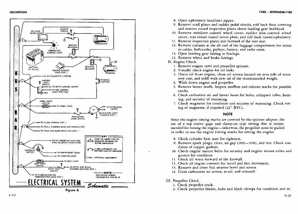
MASTER and remove round inspection plates above landing gear bulkhead.a G
AAGER SWITCHo 10. Remove stabilizer control wheel cover, rudder trim control wheel
cover, rear center tunnel cover plate, and roll back tunnel upholstery,as i -
.11. Remove inspection plates just forward of the rear seat.
- ERGENERATOR
12. Remove curtains at the aft end of the baggage compartment for access
GENERATon tO cables, bellcranks, pulleys, battery, and radio units.WAHNING LIGHT 13. Open landing gear fairing at fuselage.
14. Remove wheel and brake fairings.II. Engine Check.
BATTERY KI'ARTER I. Remove engine cowl and propeller spinner.(12 VOLTS) GROUND SERVICE
SDLENOID 2. Visually check engine for oil leaks.PLUG (OPT.) STARTER 3. Drain oil from en ine, clean oil screen located on rear side of acces-
TO CIGARETTE LIGHTER
FTARTERSOry case, and refill with new oil of the recommended weight.
U == y GHTH BUTEN 4. Wash down engine and propeller.I C TO BOTH LANDING LIGHTS 5. Remove heater muffs. Inspect mufflers and exhaust stacks for possible
TO ONE LANDING cracks.LIGHT FOR TAXI
6. Check carburetor air and heater hoses for holes, collapsed tubes, burn-ing, and security of mounting.
DOME LIGHTSWITCH 7. Check magnetos for condition and security of mounting. Check tim-
TODOME L1GHT TONAcVIGASTION ing Of m2gn€tOs, if required (22° BTC).o o NAVIGATION LIGHT
FLASHER (OPT.) NOTENAVIGATION
LIGHT SWITCB¯
Since the engine timing marks are covered by the spinner adapter, theTO FLARE SYSTEM (OPT.) USC Of 2 tOp center gage and clamp-on type timing disc is recom-
2 TO STALL WARNING HORN AND SENDING UNIT mended for timing the engine-otherwise, the propeller must be pulledTOTURNANDBANKINDICATOR(OPT.) in Order to use the engine timing marks for timing the engine.
KEYTO OIL PRESSURE GAGE AND
PURSLW-RRESET CIR 8. Check cylinder base nuts for tightness.15
FUELQUANTITYINDICATORS NOTE21AMPERAGE) 9. Remove spark plugs, clean, set gap (.016-.018), and test. Check con-
2 AMP AUTOMATIC RE-dition of copper gaskets.
CHA. TOINSTRUMENTLIGRT
SETTINGCIRCUITBRKAKER 10. Check engine mount bolts for security and engine mount tubes andTO COMPASS LIGHT guSSCtS fOf COndition.
(OPT.) OPTIONAL EQUIPMENT
I TO MAP LIGHT11. Check all wires forward of the firewall.
MAP LIGHT 12. Check all engine controls for travel and free movement.switcu
PITOTHEA-W MINGHTSET L 13. Remove and clean fuel strainer bowl and screen.
SWITCHNOTE 14. Clean carburetor air screen, re-oil, and reinstall.
TO CARBURETOR AIR FOR DETAIL WIRINGTEMPERATURE GAGE (OPT.) DIAGRAM SEE EIGURE 28
III. Propeller Check.1. Check propeller track.
Figure 6. 2. Check propeller blades, hubs and blade clamps for condition and re-
1-12 G21
CARE - RESPONSIBILITIES DESCRIPTION
best mechanics in each community to tion and service work performed by tion) and "OFF" (in position). With put. It will remain off at all times whenCessna service facilities. Many Dealers' Cessna Dealers' mechanics· the switch on, a solenoid switch is the generator is functioning properly.mechanics have attended Cessna Air- Cessna Dealers maintain stocks of energized and the electrical power of The light will not show drainage oncraft Company schools and have re- genuine Cessna parts and Service the battery and generator is admitted the battery. It will illuminate: whenceived specialized instruction in main- facilities consistent with the demand· into the electrical system. In the event the battery or external power is turnedtenance and care of Cessna airplanes. Your Cessna Dealer will be glad of a short or malfunctioning of the on prior to starting the engine; whenCessna service instruction activity in to give you current price quotations airplane's electrical system, the master there is insufficient engine RPM tothe form of service bulletins and on all parts that you might need and switch may be turned off and the en- produce generator current; and whenletters is constantly being carried on will be glad to advise you on the gine will continue to run on the mag- the generator becomes defective.so that your enjoyment and safety in practicability of parts replacement neto ignition system.your Cessna will be complete and up- versus repairs that might, from time
CIRCUIT BREAKERS. FLIGHT CONTROL SYSTEM.to-date when you have your inspec- to time, be necessary.
All the electrical circuits in the air. Conventional wheel and rudder
þläneare protected by circuit break- pedal controls are provided to operateers. The stall warning and turn-and- the primary flight control surfacesbank indicators are safeguarded by an (ailerons, rudder and elevators). Theautomatically resetting circuit breaker horizontal stabilizer is adjusted manu-
mounted behind the instrument panel ally through the use of the stabilizer(out of sight of the pilot) immediately trim control wheel located betweento the right of the glove compartment the two front seats. The rudder trim
door. The remaining electrical circuits tab is adjustable on the ground only.are protected by "push-to-reset" cir. The wing flaps are controlled by acuit breakers (see figure 5) mounted hand lever mounted between the frontbelow the glove compartment on the seats.right side of the instrument panel CONTROLS LOCK.
100 HOUR INSPECTION. The name of the circuit is indicated A controls lock is provided as stand-below each circuit breaker. .
Before beginning the inspection, the shop foreman or mechanic runs the Ifa circuit is inoperative, press theard equipment to lock the ailerons
engine to check for ignition drop, generator charging rate, oil pressure varia- circuit breaker button to reset theand elevators in neutral position.
tion, and to check smoothness and general operation of the engine, propeller, breaker. If this does not restore theThus, these control surfaces are pro-
controls, and indicators. He records these facts as an aid to the mechanic. The circuit, it should be checked for shorts, tected from damage caused by buffet-
inspection consists basically of the following procedures: defective parts, or loosened connec- ing in high winds. The controls lockI. Remove all inspection plates and fairings, consisting of the following: tions. If a circuit breaker pops out is designed with a large red metal flag
1. Remove lower half of wing root fairing (both sides)· continually, its circuit should be which covers the airplane master
2. Remove the eight inspection plates on underside of each wing checked. switch making it impossible to start3. Remove the two inspection plates on cabin top adjacent to the wing the engine with the controls lock in-
flaps. GENERATOR WARNING LIGHT. stalled. To install the controls lock, pull4. Remove tail group fairing and disconnect stinger. A generator warning light (6, fig- the control wheel back until the hole5. Remove the inspection plate on the underside of fuselage just forward ure 5) is located directly above the in the control wheel shaft is aligned
of the stabilizer. carburetor air heat control. The light, with the hole in the collar assembly6. Remove the three inspection plates on the belly of the fuselage. which is red and is labeled "GEN", mounted on the instrument panel.7. Remove rear seat back and front seats. gives an indication of generator out- Position the controls lock on the right
6-20 1-13
DESCRIPTION CARE - RESPONSIBILITIES
cense (if transmitter installed). This inspection also is performed by(4) Weight and Balance Data. your Dealer for you at no charge.(5) Airplane Log Book. While these important inspections(6) Engine Log Book. will be performed for you by any
B. To be maintained but not neces- Cessna Dealer, in most cases you willsarily carried in the airplane at all prefer to have the Dealer from whomtimes: you purchase the airplane accomplish
(1) Latest copy of the Repair and this work for you.Alteration Form 337.
(2) Equipment List. The Civil Air Regulations require
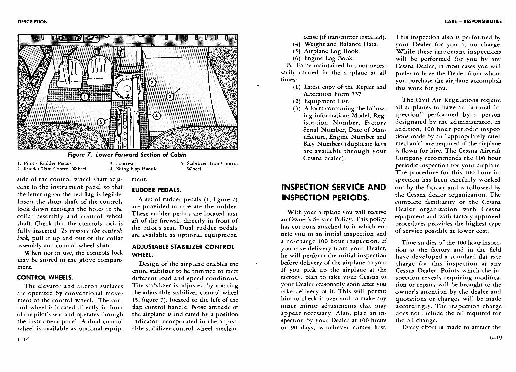
(3) A form containing the follow. all airplanes to have an "annual in-ing information: Model, Reg- spection" performed by a personistration Number, Factory designated by the administrator. InSerial Number, Date of Man. addition, 100 hour periodic inspec-ufacture, Engine Number and tions made by an "appropriately ratedKey Numbers (duplic2te keys mechanic" are required if the airplaneare available through your is flown for hire. The Cessna AircraftFigure 7. Lower Forward Section of Cobm Cessna dealer). Company recommends the 100 hour
1. Pilot's Rudder Pedals 3. Footrest 5. Stabilizer Trim Control2. Rudder Trim Control Wheel 4. Wing Flap Handle Wheel
periodic inspection for your airplane.The procedure for this 100 hour in-
side of the control wheel shaft adja- ment- spection has been carefully workedcent to the instrument panel so that RUDDER PEDALS. INSPECTION SERVICE AND out by the factory and is followed bythneseret
tshontthheared fl
ecnr A set of rudder pedals (1, figure 7) INSPECTION PERIODS. the ssna de r organizat on.e shne
lock down through the holes in the are provided to operate the rudder.. . . Dealer organization with Cessna
b These rudder pedals are located just With your airplane you will receive.collar assem ly and control wheel
aft of the firewall directly in front of an Owner's Service Policy. This policy equipment and with factory-approvedshaft. Check that the controls lock is
, procedures provides the highest type- the pilot s seat. Dual rudder pedals has coupons attached to it which en-
fully inserted. To remove the controls. of service possible at lower cost.
lock, pull it up and out of the collar are available as optional equipment. title you to an initial inspection and
assemhbC1ny and controlthehc atrhaftlock
ADJEUSTABLESTABILIZERCONTROLayno-chard 0100 hour inysper
e ertionime studiea rthe lodo hnourhinspelcd
.
- he will perform the initial inspection have develo ed a standard flat-ratemay be stored in the glove compart-
.. .
Pment Design of the airplane enables the - before delivery of the airplane to you- charge for this inspection 2t any
entire stabilizer to be trimmed to meet If you pick up the airplane at the Cessna Dealer. Points which the in-CONTROL WHEELS- different load and speed conditions. factory, plan to take your Cessna to spection reveals requiring modifica-
The elevator and aileron surfaces The stabilizer is adjusted by rotating your Dealer reasonably soon after you tion or repairs will be brought to theare operated by conventional move- the adjustable stabilizer control wheel take delivery of it. This will permit owner's attention by the dealer andment of the control wheel. The con- (5, figure 7), located to the left of the him to check it over and to make any quotations or charges will be madetrol wheel is located directly in front flap control handle. Nose attitude of other minor adjustments that may accordingly. The inspection chargeof the pilot's seat and operates through the airplane is indicated by a position appear necessary. Also, plan an in- does not include the oil required forthe instrument panel. A dual control indicator incorporated in the adjust. spection by your Dealer at 100 hours the oil change.wheel is available as optional equip- able stabilizer control wheel mechan- or 90 days, whichever comes first. Every effort is made to attract the
1-14 6-19
CARE - RESPON5\BILITIE5 DE5CRIPTION
i Texaco Regal Starfak Special· ism. Forward movement of the wheel position indicator should be in the
McCauley propeller - On assembly, lubricate propeller with MIL- trims the nose down. Backward move- neutral position as indicated by theL-7711 grease. Using a suitable applicator, 102d the bottom race of ment of the wheel trims the nose up. white neutral mark. Prior to take-off
each blade retention bearing with lubricant, apply a circumferen. This allows the elevator forces to be and climb, the trim control wheel may
tial ring of lubricant to the preload bearing race of each blade, trimmed out for the various load and be rotated approximately 2 turns
apply approximately one tablespoon of lubricant in each of the flight conditions. (Control wheel loads clockwise.
eight pockets on the inside of the hub behind the blade bore diam- are very heavy when the stabilizer is WING FLAP HANDLE.eter, and apply a small amount of lubricant around the outer two
· not properly set.) Take-off is made
retention nut threads in the hub. with indicator in "TAKE-OFF" posi- The wing flaps are controlled by ation. wmg flap control handle (3, figure 7)
F -- Adjustable Stabilizer Jack - Coat threads with MIL-L-7711 grease mounted between the two front seats.
every 500 hours or whenever stabilizer is removed. RUDDERTRIM CONTROL WHEEL. The handle is operated by depressingNOTE 1. All pulleys, control surface hinge beanngs, bellcrank clevis bolts,flap A rudder trim system is installed the thumb button and moving theactuating handle, brake pedal pivots, rudder pedal crossbars, door hinge and in the airplane to provide a means of handle to the desired flap setting. Bymechanism, Bowden controls, throttle, control rod universal (if unsealed) and directional trim. The system also in. releasing the thumb button, the han-control column balls, should be lubricated with SAE 20 General Purpose light creases directional stability and is die can be locked to provide 0,10,20,machine oil as required or every 1,000 hours. especially useful during "climb-out" 30 and 40 degree flap positions.
operations when the engine is operat- The flaps may be lowered or raisedNote 2. In general, roller chains and control cables tend to collect dust, sand' ing at nearly full power and the air. during normal flying whenever theand grit when greased or oiled. More satisfactory operation, except under sea¯
plane forward speed is relatively low. airspeed is less than 100 mph. Thecoast conditions, results when the chains are wiped clean occasionally with a The trim system compensates for fl2ps supply considerable added liftclean dry cloth.
engine torque by applying slight and drag; the resulting action steep-
rudder control in the direction neces- ens the glide angle of the airplane en-whenever the setting is changed.
sary for maintaining straight forward abling the pilot to bring the airplaneNever rotate them separately. If flight night.Under cruising conditions, the in over an obstruction and land short-test shows excessive wing heaviness'
rudder trim system may be adjusted er than could be done without flaps.re-rig by rotating the proper bush- The use of flaps is not recommend-' ings, which will increase or decrease to maintain directional trim at any
ed for take-offs in strong cross-winds.the angle of attack of the wing. power setting.
. For additional information on the useThe system is operated by the .
AIRPLANE FILE. rudder trim control wheel (2, figure of wing flaps for take-off, refer to
There are miscellaneous data, in- 1-7). Clockwise rotation of the con- page 3-4.
formation and licenses that are a part trol wheel provides "NOSE RIGHT" Wing Flap Settingsof the airplane file. The following is a trim, and counterclockwise rotation For take-off. . . . . . . . . . . . . . . . . Up (0°)check list for that file: provides "NOSE LEFT" trim. A 1st notch (10°)
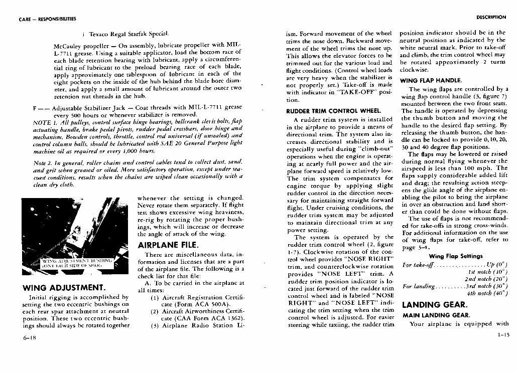
WING ADJUSTMENT A. To be carried in the airplane at rudder trim position indicator is lo- 2nd notch (20°)• all times: cated just forward of the rudder trim For landing. . . . . . . . . .3rd notch (30°)
Initial rigging is accomplished by (1) Aircraft Registration Certifi- control wheel and is Iabeled "NOSE 4th notch (40°)setting the two eccentric bushings on cate (Form ACA 500A). RIGHT" and "NOSE LEFT" indi- LANDING GEAReach rear spar attachment at neutral (2) Aircraft Airworthiness Certifi- cating the trim setting when the trimposition. These two eccentric bush- cate (CAA Form ACA 1362). control wheel is adjusted. For easier MAIN LANDING GEAR.ings should always be rotated together (3) Airplane Radio Station Li- steering while taxiing, the rudder trim Your airplane is equipped with
6-18 1-15
DESCRIPTION CARE -- RESPONSIBILITIES
Cessna's "Land-O-Matic" landing gear. LUBRICATIONIt consists of a tapered, spring-steel BRAKES RELEASED '
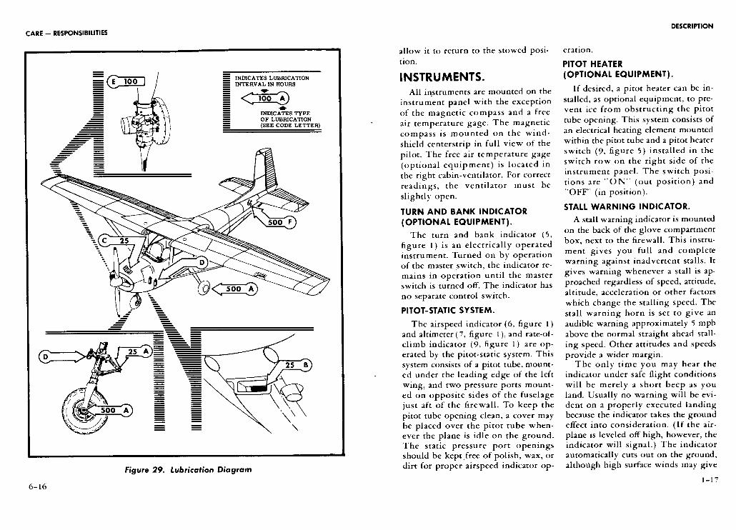
leaf supporting each main wheel. This Figure 29 outlines the lubric2tion requirements for your airplane.
spring leaf is made from the highest LUBRICATION CODEquality chrome-vanadium steel; heat- Code Lettertreated and shot-peened for added A - - MIL-L-7711 - Greasefatigue resistance. \ B - - Carburetor Air Filter - Service every 25 hours or oftener when
NOSE GEAR. operating in dusty conditions. Under extremely dusty conditions,
A steerable nose gear, incorporating daily maintenance of the air filter is recommended. Service the air
an air and oil shock strut, is mounted eaA Es filter in accordance with the servicing instructions stamped on the
on the firewall. Nose wheel steering is .g
filter.accomplished through normal opera- C - - Engine Oil Tank - Check dip-stick before each flight. Drain and
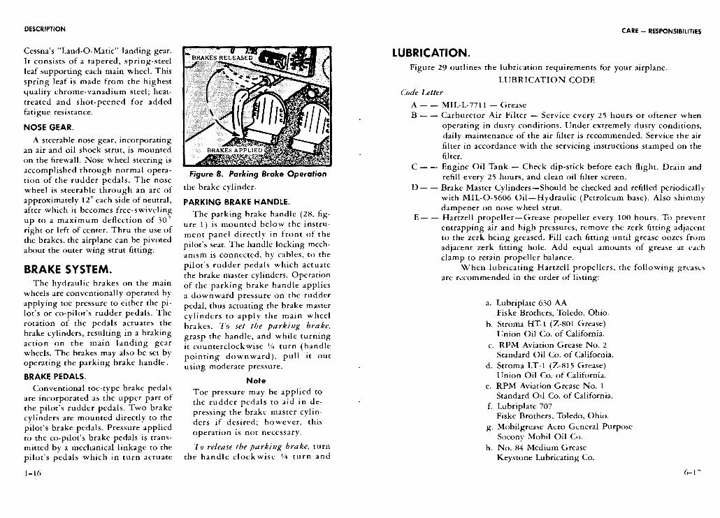
tion of the rudder pedals. The noseFigure 8. Parking Brake Operation refill every 25 hours, and clean oil filter screen.
wheel is steerable through an arc of the brake cylinder. D-- Brake Master Cylinders-Should be checked and refilled periodicallyapproximately 12° each side of neutral, PARKING BRAKE HANDLE. with MIL-O-5606 Oil--Hydraulic (Petroleum base). Also shimmyafter which it becomes free-swiveling .
dampener on nose wheel strut.. . The parking brake handle (28, fig-
up to a maximum deflection of 30 .
E--- Hartzell propeller-Grease propeller every 100 hours. To prevent.
ure 1) is mounted below the instru-right or left of center. Thru the use of . .
entrapping air and high pressures, remove the zerk fitting adjacent. ment panel directly in front of the
the brakes, the airp12ne can be pivoted . , .to the zerk being greased. Fill each fitting until grease oozes from
about the outer wing strut fitting. pilot s seat. The handle lockmg mech.adjacent zerk fitting hole. Add equal amounts of grease at cach
anism is connected, by cables, to the clamp to retain propeller balance.BRAKE SYSTEM. pilot's rudder pedals which actuate When lubricating Hartzell propellers, the following greases
the brake master cylinders. Operation are recommended in the order of listing:The hydraulic brakes on the main of the parking brake handle applieswheels are conventionally operated by a downward pressure on the rudderapplying toe pressure to either the pi¯ pedal, thus actuating the brake master a. Lubriplate 630 AAlot's or co-pilot's rudder pedals. The cylinders to apply the main wheel Fiske Brothers, Toledo, Ohio.rotation of the pedals actuates the brakes. To set the parking brake. b. Stroma HT-1 (Z-801 Grease)brake cylinders, resulting in a braking grasp the handle, and while turning Union Oil Co. of California.action on the main landing gear it counterclockwise ¼ turn (handle c. RPM Aviation Grease No. 2wheels. The brakes may also be set by pointing downward), pull it out Standard Oil Co. of California.operating the parking brake handle.
using moderate pressure. d. Stroma LT-1 (Z-815 Grease)BRAKE PEDALS. Union Oil Co. of California.Note
Conventional toe-t e brake edals e. RPM Aviation Grease No. 172 E Toe pressure may be applied to .
are incorporated as the upper part of . . Standard Oil Co. of California.the rudder pedals to aid in de-
.
the pilot's rudder pedals. Two brake . f. Lubriplate 707. pressing the brake master cylin-
.
cylinders are mounted directly to the . . . Fiske Brothers, Toledo, Ohio.ders if desired; however, thispilot's brake pedals. Pressure applied g. Mobilgrease Aero General Purpose
operation is not necessary.to the co-pilot's brake pedals is trans- Socony Mobil Oil Co.mitted by a mechanical linkage to the To release the parking brake, turn h. No. 84 Medium Greasepilot's pedals which in turn actuate the handle clock wise ¼ turn and Keystone Lubricating Co.
1-16 T-I¯
CARE - RESPONSIBILITIES DESCRIPTION
allow it to return to the stowed posi- eration.
-
tion. PITOT HEATER-( loo I
¯
HOICA LSLUBORICATION INSTRUMENTS. (OPTIONAL EOUIPMENT).
lIo AIl instruments are mounted on the If desired, a pitot heater can be in-instrument panel with the exception stalled, as optional equipment, to pre-
mDICATESTYPE of the ma netic com ass and a free vent ice from obstructing the pitot- OF LUBRICATION
.
(SEE CODE LETTER) 21r temperature gage. The magnetic tube opening. This system consists ofcompass is mounted on the wind. an electrical heating element mounted
shield centerstrip in full view of the within the pitot tube and a pitot heaterpilot. The free air temperature gage switch (9, figure 5) installed in the(optional equipment) is located in switch row on the right side of the
the right cabin-ventilator. For correct instrument panel. The switch posi-readings, the ventilator must be tions are "ON" (out position) andslightly open. "OFF" (in position).
TURN AND BANK INDICATOR STALLWARNING INDICATOR.500 F (OPTIONAL EQUIPMENT). A stall warning indicator is mounted
The turn and bank indicator (5, on the back of the glove compartmentC 25 °
- - box, next to the firewall. This instru-figure 1) is an electrically operatedinstrument. Turned on by operation ment gives you full and complete
't. D of the master switch, the indicator re- warning against inadvertent stalls. It
mains in operation until the m2ster gives warning whenever a st211 is ap-
Û 500 switch is turned off. The indicator has proached regardless of speed, attitude,
no separate control switch. altitude, acceleration or other factorswhich ch2nge the stalling speed. ThePITOT-STATICSYSTEM. stall warning horn is set to give an
--¯
The 2irspeed indicator (6, figure 1) audible warning approximately 5 mph- -- and altimeter (7, figure 1), 2nd rate-of- above the normal straight ahead st211-
25 A---- climb indic2tor (9, figure 1) are op- ing speed. Other attitudes 2nd speeds
. - erated by the pitot-static system. This provide a wider margin.25 B system consists of a pitot tube, mount- The only time you may hear the
- ed under the leading edge of the left indicator under safe flight conditionswing, and two pressure ports mount- will be merely a short beep as youed on opposite sides of the fusel2ge land. Usually no warning will be evi-
500 just aft of the firewall. To keep the dent on 2 properly executed landing- pitot tube opening clean, a cover may because the indicator takes the ground
be pl2ced over the pitot tube when- effect into consider2tion. (If the air-
ever the plane is idle on the ground. plane is leveled off high, however, theThe st2tic pressure port openings indicator will signal.) The indic2torshould be kept free of polish, w2x, or autom2tically cuts out on the ground,
Figure 29. Lubrication Diagram dirt for proper 2irspeed indicator op- although high surface winds m2y give
6-16 1-17
DESCRIPTION CARE - RESPONSIBIUTIES
signals when taxiing. It therefore re- NOTEquires no silencing switch which Test the front seats for secure EØTHEATSWTrCH(OPT.)
might be inadvertently left off latching after adjusting them toSTALLWARNING TRANSMITTER the desired position. CARBURETOR AIR TEMP. GAGE (OPT.)
HEATER(OPTIONAL EOUIPMENT) REAR SEAT.If desired, a heater can be installed, The rear seat has provisions to ac- ER
as optional equipment, to prevent ice commodate two people. The back of OIL PRESBURE GAGEfrom hampering operation of the stall the seat is hinged at the bottom to a ,warning system transmitter unit permit seat adjusement and easy accessmounted on the leading edge of the to the baggage compartment. A seat - a
SGHT TANE FUEL
left wing. The heater element is in adjustment handle is located behind ,,INDICATOR
stalled when an optional pitot heater and at the top of the rear seat back a oiifWEL U
is provided on your airplane. The omrcaron $heater is operated by the pitot heater CABIN TEMPERATURE COMPABOUGHTswitch (9, figure 5) CONTROL SYSTEM. gm < +- e..o.xxx.wac" aCLOCK (OPTIONAL EQUIPMENT)· The cabin temperature control sys- '
¤ n AAn ei ht-da
, stem-wind, aircraft tem was designed to provide fresh air wrALLWARNKNG TURNANDBANKË Ï HORN DGECATOR (OPr.)clock (4, figure 1) may be installed as to the cabin at all times, with a means aoptional equipment in the upper left of regulating the air temperature. Ng
hand corner of the instrument panel. Cabin temperature is controlled by .
*
MAGNETIC COMPASS. a cabin heat knob (8, figure 2) locatedimmediately below the mixture con- GENERATORWARNDELIGHT
A magnetic compass is mounted on trol. With the cabin heat knob pushedthe windshield center strip. The com full in, unheated air is ducted to the wrARTERSWYrCH
pass correction card is mounted on cabin. As the knob is pulled out, * * -la
the instrument panel in full view of more and more heated air is added. FLASHER (OPT) gg'gthe pilot for quick and easy reference With the knob pulled all the way NAVUkr!DNwhen reading the magnetic headings out, all of the air entering the cabin as se
LEHTSSWYrCH
TO HIGHT WING - - 37 githrough the cabin temperature control TO TAII£ØNE-38 38SEATS. system is heated. **
LANIENG LIGHTS SWITCH (OPT.)Air outlets are provided in front of
FRONT SEATS· the pilot's and co-pilot's rudder pedals '°aàËinn».a M
CIGARETTE LlGHTER
The front seats are individually and at the door posts. The forwardmounted on tracks and are adjustable outlets are ten holes in each end of afore and aft. The seat adjustment han- duct running completely across thedle is located within easy reach on the firewall. The rear cabin area is heated IGNirION SWrrCH
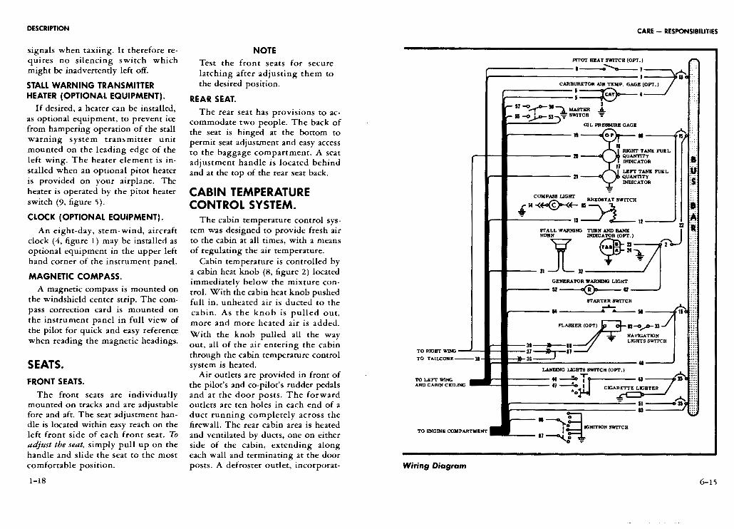
. TO ENGINE COMPARTMENTleft front side of each front seat. To and ventilated by ducts, one on either siadjust the seat, simply pull up on the side of the cabin, extending alonghandle and slide the seat to the most each wall and terminating at the doorcomfortable position. posts. A defroster outlet, incorporat- Wiring Diagram1-18 6-15
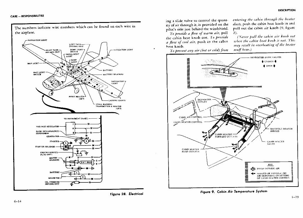
CARE - RESPONSIBILITIES DESCRIPTION
ing a slide valve to control the quant- entering the cabin through the heaterThe numbers indicate wire numbers which can be found on each wire in ity of air through it, is provided on the ducts, push the cabin heat knob in and
the airplane. pilot's side just behind the windshield. pull out the cabin air knob (9, figureTo provide a flowof uarm air, pull 2).
NAVIGA11ONUGHT the cabin heat knob out. To provide (Never pull the cabin air kuoh outLEFTTANK a flowof cool air, push in the cabin uhen the cahin heat knob is out. This
RIGiff TANKEMLI
H NAVIGATION LIGHT *
heat knob. nury result in overheating of the heaterSENDING WR INSTW1 " To prevent any air (hot or cold) from ninff hoses.)
LIGHT
DOME -- DEFROSTER SLIDE VALVESMAP UGHT LIGHT
CLOSED
13g 1 55 OPEN
MAP UGHTBATTERY
SWITCH Ž1
5 BATTERY SOLENOID
11NAVIGATIONLlGHT
LA DING LIGHTS
T R HEA
UTLET
TO INSTRUMENT PANEL CABIN AIR CONTROL
CABUNHEATERCONTROLVOLTAGE REGULATOR
RADIO INTERFERENCE rSUPPRESSDR $1 / MANIFOLD HEATER
GENERATOR $4 CABIN HEATERSffROUD
A FORWARD OUTLETS /STANTER 55
STARTER SOLENOIDCABINEHEATER
PS VICEE
N HEAL
L
55 i. _KE
nATTrar FRESH OUTSIDE AIR
MAGNETOS HEATED OR VENTILATINGgl-.-- AIR DEPENDING ON SETTING .
Dp OF CABIN HEATER CONTROL
Figure 28. Electrical Figure 9. Cabin Air Temperature System6--14 1-19
DESCRIPTION CARE - RESPONSIBILITIES
To stop the flow of air, push theROTATE TO DIRECT AIR ventilator tube all the way in.
LIGHTING EQUIPMENT.NAVIGATION LIGHTS.
The navigation lights consist of ared light on the left wing tip, a greenlight on the right wing tip, and a //
( ABIN VE\TIl ATOR (OPEN) white light on the tip of the fuselagestinger. The navigation light switch(3, figure 5) is mounted in the switch /
CABIN VENTILATORS. row on the instrument panel. To turnthe navigation lights on, pull the navi-
Additional ventilation for the cabin gation light switch out. To turn the
area is provided by manually-adjusted lights off push the switch in.
cabin ventilators. Two ventilators are. - NAVIGATION LIGHTS FLASHERinstalled: one on each side of the cabin
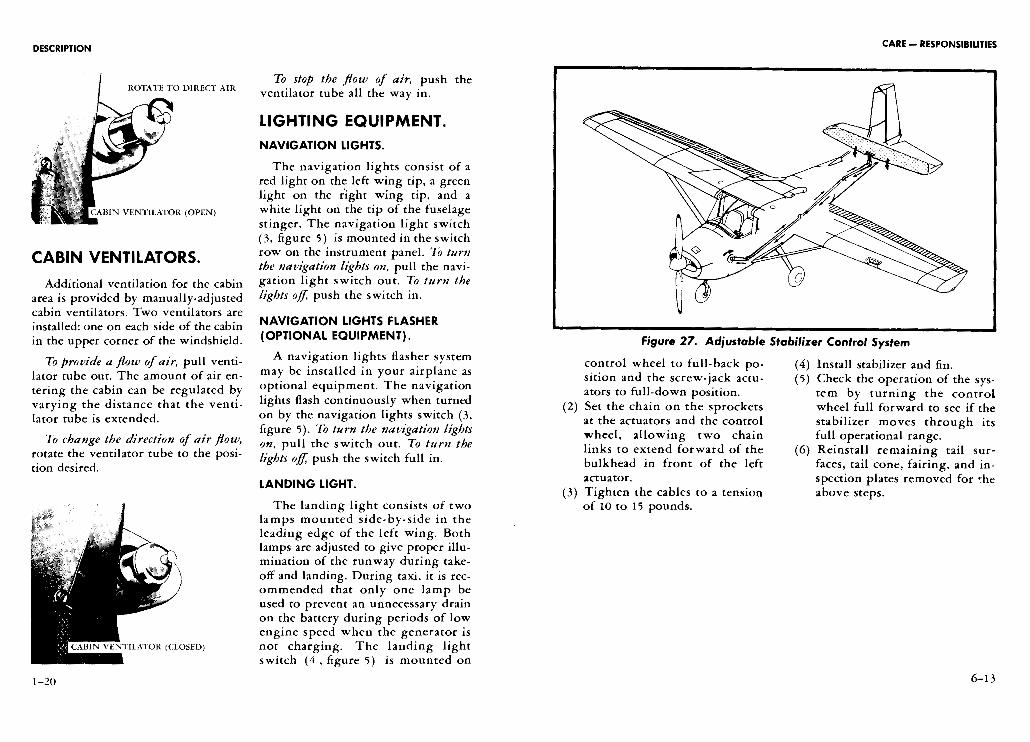
in the upper corner of the windshield. (OPTIONAL EOUIPMENT)· Figure 27. Adjustable Stabilizer Control System
To provide a flowofair, pull venti- A navigation lights flasher system control wheel to full-back po- (4) Install stabilizer and fin.lator tube out. The amount of air en- may be installed in your airplane as sition and the screw-jack actu- (5) Check the operation of the sys-tering the cabin can be regulated by optional equipment. The navigation ators to full-down position. tem by turning the controlvarying the distance that the venti- lights flash continuously when turned (2) Set the chain on the sprockets wheel full forward to see if thelator tube is extended. on by the navigation lights switch (3, at the actuators and the control stabilizer moves through its
.
figure 5). To turn the navigation lights wheel, 2110wing two chain full operational range.To change the direction of air flour, on, pull the switch out. To turn the links to extend forward of the (6) Reinstall remaining tail sur-rotnate te ventilator tube to the posi- lights off push the switch full in· bulkhead in front of the left faces, tail cone, fairing, and in-
2ctuator. spection plates removed for theLANDING LIGHT.(3) Tighten the cables to a tension above steps.
The landing light consists of two of 10 to 15 pounds.lamps mounted side-by-side in theleading edge of the left wing. Bothlamps are adjusted to give proper illu-mination of the runway during take-
off and landing. During taxi, it is rec-
ommended that only one lamp beused to prevent an unnecessary drainon the battery during periods of lowengine speed when the generator is
CABIN VENTILATOR (CLOSED) ROt charging. The landing lightswitch (4 , figure 5) is mounted on
1-20 6-13
CARE - RESPONSIBILITIES DESCRIPTION
RUDDER TAB.25°±1° up and 23° ±1° down. the instrument panel. To turn one To turn the lights off turn the knob
(4) With elevator in full down po- lamp on for taxiing, pull the switch counterclockwise.The rudder tab is a fixed tab locat sition, the measurement from out to the first stop. To turn both
ed on the trailing edge of the rudder firewall to the edge of the chain lamps on for landing, pull the switch l)OME LIGHTand can be set by bending, in either sprocket hub on the control col- out to the second stop. To turn lights DOME LIGHT SWITCHdirection, the amount desired.
umn should be ½ ". off push the switch all the way in.
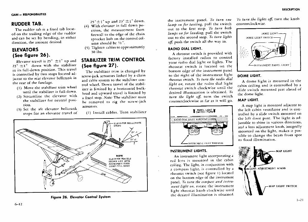
ELEVATORS (5) Tighten cables to approximately- RADIO DIAL LIGHT.
(See figure 26). 30 lbs.A rheostat switch is rovided with .
*
Elevator travel is 25° ±1° up and STABILIZERTRIM CONTROL factory installed radios to control23° ±1° down with the stabilizer (See figure 27) your radio dial light or lights. Thein its full-down position. This travel rheostat switch is located on the INSTRUMENT PANEL LIGHT
is controlled by two stops located ad- The stabilizer trim is changed by bottom edge of the instrument paneljacent to the rear elevator bellcrank in screw-jack actuators linked by a chain to the right of the instrument light DOME LIGHT.the rear of the fuselage. and cable system to the stabilizer con- rheostat switch. To turn the radio dial
.
trol wheel. Down travel of the stabil- light on, rotate the radio dial light A dome light is mounted in the(1) Move the stabilizer trim wheel
izer is limited by a horizontal bulk- rheostat switch clockwise until the cabin ceiling and is controlled by auntil the stabilizer is full-down-
- . . . slide switch mounted ust ahead of. . head and upward travel is limited by desired illumination is obtained. To(2) Streamline the elevator with the dome li hta fixed stop. Note: The stabilizer must turn the light off turn the switchte stabilizer for neutral posi-
be removed to rig the screw-jack counterclockwise as far as it will go. MAP LIGHT.
(3) Set the aft elevator bellcrank actuators· A map light is mounted adjacent to
stops for an elevator travel of (1) Install cables. Turn stabilizer (s", g¿g the left cabin ventilator and is con-trolled by a slide switch mounted on
KADIODIAI.l.lGill RIUMAIAT the left door post. The light is ad-sE EVSANR BELLCRANK justable to shine in various directions,
and a lens adjustment knob, integrally25 1 mounted on the light, makes it pos-
sible to change the beam from spot23 1
to flood illumination.INSTRUMENT LIGHT RHEOSTAT
INSTRUMENT LIGHTS. MAP LIGHT
y ELEVA VELS An instrument light incorporating aSHOWN ARE WITH red lens is mounted in the cabinADJIETABLE STABI-
7, LIZERFULLDOWN ceiling. The light, in conjunction with -
a compass light, is controlled by a g LENS ADJUSTMENT KNOBrheostat switch (see figure 1) locatedon the bottom edge of the instrumentpanel. 7o turn the compass and instru-ment light on. rotate the instrument MAP LIGHT SWITCHIight rheostat knob clockwise until
Figure 26. Elevotor Control System the desired illumination is obtained.
12 l--2 I
DESCRIPTION CARE - RESPONSIBILITIES
MISCELLANEOUS cABIN WINDOWS.. . RUDDER TRIM RUDDER TRIM
EQUIPMENT. The rear cabin windows are of the CONTROLWHEEL CONTROLWHEEL
fixed type and do not open. The cabin avons, taggœvn
CABIN DOORS- door windows are a full door width, PommONEDICATOR
Two cabin doors are provided on providing you with excellent side vis-
your airplane. Each door incorporates ibility. They are hinged along the top BUNGEE ASSEMBLT
a Rush type door handle on the out- allowing them to open outward for . • RUDDERPRIMARTw \ CONTROL CABLES
side .and a conventional type door additional ventilation.handle on the inside. To open these windows, depress the
To open the door from the outside, small lock release button and turn the PIIDT'S RUDDER PEDAL
apply pressure on the forward end of handle upward. The window will'
the Bush handle, and pull out on the open outward without pressure due RUDDER RETURN
aft end of the handle until the door to spring loaded limit arms in the * ERP L CONTROLCABLE
latch releases. To open the door from upper portion of the window.
the inside, rotate inside door handle NOTE n°•1°down and forward.
Caution should be exercisedNOTE when opening these windows
24°**°
When closing the door, the in- during nightsince air pressureside door handle must be in the will tend to "pop"' them out-unlocked position (neutral). ward with considerable force.Otherwise, the locking bolt This may result in damage to /will interfere with the door the limit arms. Therefore it isjamb. recommended that you hold
firmly to the handle and easeBoth cabin doors can be locked the window outward to its
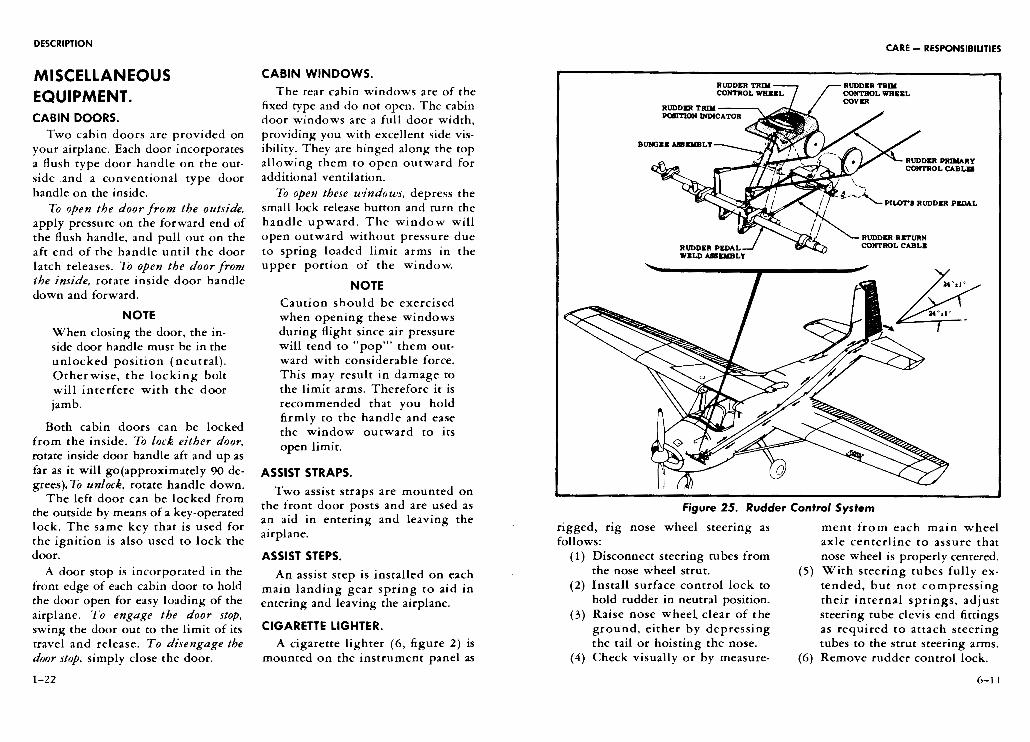
from the inside. To lock either door, open limit.rotate inside door handle aft and up asfar as it will go(approximately 90 de- ASSIST STRAPS. Ogrees). To unlock, rotate handle down. Two assist straps are mounted onThe left door can be locked from the front door posts and are used as Figure 25. Rudder Control S stemthe outside by means of a key-operated
. .Y
an aid in entering and leaving the. .
lock. The same key that is used for . rigged, rig nose wheel steering as ment from each main wheelthe ignition is also used to lock the
airplane. follows: axle centerline to assure thatdoor. ASSIST STEPS. (1) Disconnect steering tubes from nose wheel is properly centered.
A door stop is incorporated in the An assist step is installed on each the nose wheel strut. (5) With steering tubes fully ex-
front edge of each cabin door to hold main landing gear spring to aid in (2) Install surface control lock to tended, but not compressingthe door open for easy loading of the entering and leaving the airplane. hold rudder in neutral position. their internal springs, adjustairplane. To engage the door stop, (3) Raise nose wheel. clear of the steering tube clevis end fittingsswing the door out to the limit of its CIGARETTE LIGHTER- ground, either by depressing as required to attach steeringtravel and release. To disengage the A cigarette lighter (6, figure 2) is the tail or hoisting the nose. tubes to the strut steering arms.door stop, simply close the door. mounted on the instrument panel as (4) Check visually or by measure- (6) Remove rudder control lock.
1-22 6--1 i
CARE - RESPONSIBILITIES DESCRIPTION
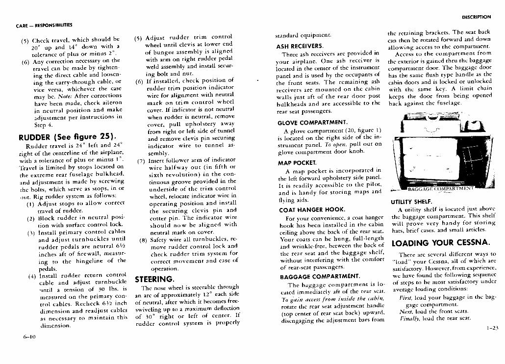
(5) Check travel, which should be (5) Adjust rudder trim control standard equipment. the retaining brackets. The seat back
20° u and 14° down with a wheel until clevis at lower end can then be rotated forward and down. ASH RECEIVERS.
tolerance of plus or minus 2 . of bungee assembly is aligned.
allowing access to the compartment.(6) Any correction necessary on the with arm on right rudder pedal Three ash receivers are provided in Access to the compartment from
travel can be made by tighten- weld assembly 2nd install secur- your airplane. One ash receiver is the exterior is gained thru the baggageing the direct cable and loosen- ing bolt and nut. located in the center of the instrument compartment door. The baggage dooring the carry-through cable, or (6) If installed, check position of panel and is used by the occupants of has the same flush type handle as the
vice versa, whichever the case rudder trim position indicator the front seats. The remaining ash cabin doors and is locked or unlocked
may be. Note: After corrections wire for alignment with neutral receivers are mounted on the cabin with the same key. A limit chainhave been made, check aileron mark on trim control wheel walls just aft of the rear door post keeps the door from being opened
in neutral position and make cover. If indicator is not neutralbulkheads and are accessible to the back against the fuselage.
adjustment per instructions in when rudder is neutral, removerear seat passengers.
Step 4· cover, pull upholstery away GLOVE COMPARTMENT.
RUDDER (See figure 25). from right or left side of tunnel A glove compartment (20, figure 1)and remove clevis pin securing is located on the right side of the in-
Rudder travel is 24° left and 24 indicator wire to tunnel as strument panel. To open, pull out onright of the centerline of the airplane, blsem y· glove compartment door knob.with a tolerance of plus or minus I (7) Insert follower arm of indicatorTravel is limited by stops located on wire halfway out (in fifth or MAP POCKET.the extreme rear fuselage bulkhead, sixth revolution) in the con. A map pocket is incorporated inand adjustment is made by screwing tinuous groove provided in the the left forward upholstery side panel.the bolts, which serve as stops, in or underside of the trim control It is readily accessible to the pilot,out. Rig rudder system as follows: wheel, relocate indicator wire in and is handy for storing maps and ik BAGGAGE COMPARTMEN I
(1) Adjust stops to allow correct operating position and install flying aids.UTILITYSHELF.
B ocrurdddedrCL
neutral osi-the securing clevis pin and COAT HANGER HOOK· A utility shelf is located just above(2) p cotter pin. The indicator wire -
tion with surface control lock . .
For your convenience, a coat hanger the baggage compartment. This shelf
(3) Install primary control cablesshould norw be aligned with hook has been installed in the cabin will prove very handy for storing
. .
neutr ma on cover· ceiling above the back of the rear seat. hats, brief cases, and small articles.and adjust turnbuckles until (8) Safety wire all turnbuckles, re- Your coats can be hung, full-lengthrudder pedals are neutral 6½ move rudder control lock and and wrinkle-free, between the back of LOADING YOUR CESSNA.inches aft of firewall, measur- check rudder trim system for the rear seat and the baggage shelf,ing to the hingeline of the correct movement and ease of without interfering with the comfort ,,
There are several different ways topedals. load' your Cessna, all of which areoperation- of rear-seat passengers.
(4) Install rudder return control satisfactory. However, from experience,
cable and adjust turnbuckle STEERING. BAGGAGE COMPARTMENT. we have found the following sequence
until a tension of 30 lbs. is The nose wheel is steerable through The baggage compartment is 10. of steps to be most satisfactory under
measured on the primary con- an arc of approximately 12° each side cated immediately aft of the rear seat. average loading conditions:trol cables. Recheck 6½ inch of neutral, after which it becomes free- To gain access from inside the cabin, First, load your baggage in the bag-
dimension and readjust cables swiveling up to a maximum deflection rotate the rear seat adjustment handle gage compartment.
as necessary to maintain this of 30° right or left of center. If (top center of rear seat back) upward, Next, load the front seats.
dimension. rudder control system is properly disengaging the adjustment bars from Pinally, load the rear seat.
6--10 1-23
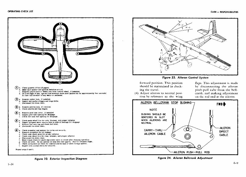
OPERATING CHECK LIST CARE - RESPONSIBILITIES
6
Figure 23. Aileron Control System
2 forward position. This position flaps. This adjustment is madeshould be maintained in check- by disconnecting the aileron
a. Check quantity of fuel (2 gages).b. Makesuremasterandignitionswitcheaareott. ing the travel. push-pull tube from the bell-c. Remove control lock or safety belt from control wheel, if installed . .
d. On first flight of day, operate fuel strainer drain knob (pulled out for approximately four seconds) (4) Adjust aileron to neutral posi- crank, and making ad¡ustmentto clear fuel strainer of any water or sediment tion by reference to the wing on the rod end at the aileron.
a. Remove rudder lock, if installed.b a tall a dacenhinghaenaand hinge bolt. AILERONBELLCRANK STOP BUSHING FWDa. Remove alleron lock, if installed.b. Check alleron and flap binge. NOTE
nte N c f
e. BUSHING SHOULDBE oc Check fuel tank vent opening for stoppage. CENTERED IN SLOTa Check main wheel tire 1er cuts, bruises, and proper Inflation. WHEN AILERONS AREb Inspect airspeed static source hole on side of fuselage for stoppage NEUTRAL.c Remove fuel tank cap and check fuel level.d Disconnect tie-down chain. AILERONa Check propeller and spinner for nicks and security. CARRY - THRU DIRECTb Examine propener for oil leakage.c Check nose wheel stat for proper inflation. AILERON CABLE CABLEd Check nose wheel tire for cuts, bmises, and proper inflation.e Disconnect tie-down chain.f. Make visual check to insure that drain valve is closed after draining operation.g. Check oH level. Do not operate on less than nine quarts. Fill for extended flight.h. Check carburetor air filter for restrictions by dust or other foreign matter.i. Inspect cowl access doors for security.
Repeat steps 3 and 5.
AILERON PUSH- PULL ROD
Figure 10. Exterior inspection Diagram Figure 24. Aileron Bellcronk Adjustment
1-24
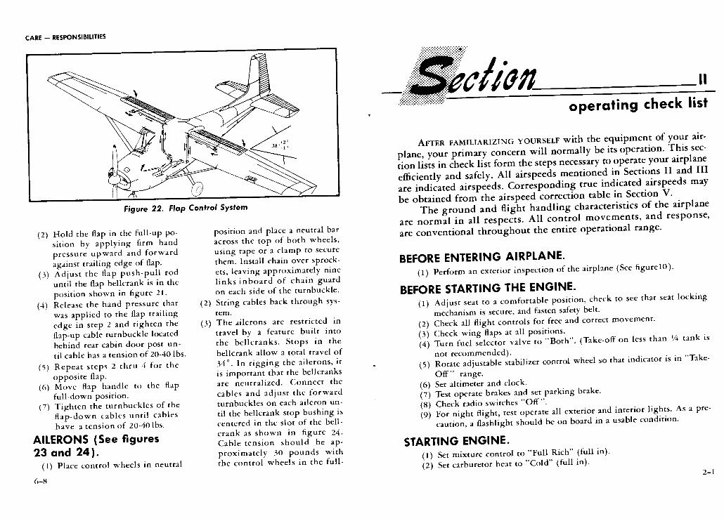
CARE - RESPONSIBILITIES
operating check list
AFTER FAMILIARIZING YOURSELF with the equipment of your air-plane, your primary concern will normally be its operation. This sec-tion lists in check list form the steps necessary to operate your airplaneefficiently and safely. All airspeeds mentioned in Sections II and IIIare indicated airspeeds. Corresponding true indicated airspeeds may
Figure 22. Flap Control System be obtained from the airspeed correction table in Section V.The ground and flight handling characteristics of the airplane
. are normal in all respects. All control movements, and response,(2) Hold the flap m the full-up po- position and place a neutral bar . .
sition by applying firm hand across the top of both wheels, are conventional throughout the entire operational range.
pressure upward and forward using tape or a clamp to secureagainst trailing edge of flap. them. Install chain over sprock BEFORE ENTERING AIRPLANE.
(3) Adjust the flap push-pull rod ets, leaving approximately nine. .
. (1) Perform an exterior inspection of the airplane (See figure10).until the flap bellcrank is in the links inboard of chain guardposition shown in figure 21. on each side of the turnbuckle· BEFORE STARTING THE ENGINE.
(4) Release the hand pressure that (2) String cables back throu hs s-(1) Adjust seat to a comfortable position, check to see that seat locking
was applied to the flap trailing tem.. . . mechanism is secure, and fasten safety belt.edge in step 2 and tighten the (3) The ailerons are restricted in
flap-up cable turnbuckle located travel by a feature built into (2) Check all flight controls for free and correct movement.
behind rear cabin door post un. the bellcranks. Sto s in the (3) Check wing flaps at all positions.(4) Turn fuel selector valve to "Both". (Take-off on less than ¼ tank istil cable has a tension of 20-40 lbs. bellcrank allow a total travel of
o . . not recommended).(5) Repeat steps 2 thru 4 for the 34 . In rigging the ailerons, it . . . ,,
. (5) Rotate adjustable stabilizer control wheel so that indicator is in Take-opposite flap. is important that the bellcranks
,,
(6) Move flap handle to the flap are neutralized. Connect theOff range.
(6) Set altimeter and clock.full-down position. cables and adjust the forward. (7) Test operate brakes and set parking brake.(7) Tighten the turnbuckles of the turnbuckles on each aileron un-
,,(8) Check radio switches "Off .flap-down cables until cables til the bellcrank stop bushing is .
(9) For night flight, test operate all exterior and interior lights. As a pre-have a tension of 20-40 lbs. centered in the slot of the bell-
. . .
caution, a flashlight should be on board in a usable condition.AILERONS(See figures crank as shown in figure 24.
23 and 24, Cable tension should be ap STARTING ENGINE.i• proximately 30 pounds with(1) Place control wheels in neutral the control wheels in the full- (1) Set mixture controI to "Full Rich" (full in).
(2) Set carburetor heat to "Cold" (full in).6-8
2-1
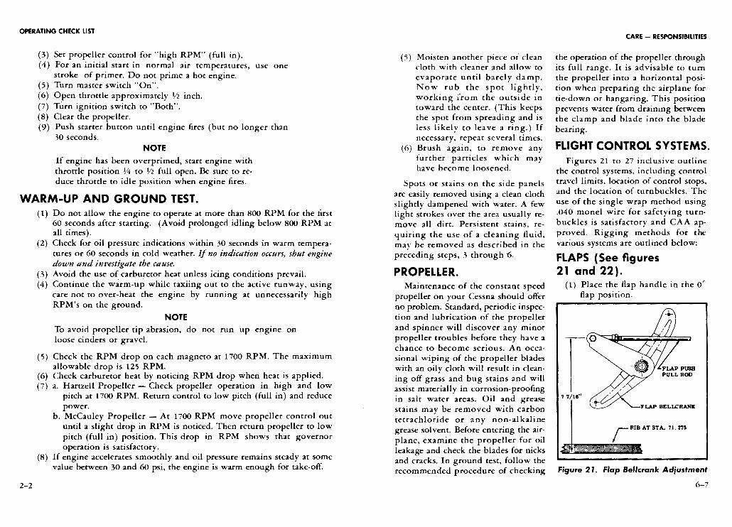
OPERATING CHECK LISTCARE - RESPON5tBILITIES
(3) Set propeller control for "high RPM" (full in)- (5) Moisten another piece of clean the operation of the propeller through(4) For 2n initi21 start in normal air temperatures, use one cloth with cleaner and allow to its full range. It is advis2ble to turn
stroke of primer. Do not prime a hot engine. evaporate until barely damp. the propeller into 2 horizontal posi-(5) Turn master switch "On". Now rub the spot lightly, tion when prep2ring the airplane for(6) Open throttle approximately ½ inch. working from the outside in tie-down or hangaring. This position(7) Turn ignition switch to "Both". toward the center. (This keeps prevents water from draining between(8) Cle2r the propeller. the spot from spreading and is the clamp and blade into the blade(9) Push starter button until engine fires (but no longer than less likely to leave a ring.) If bearing.
30 seconds. necessary, repeat several times.
NOTE (6) Brush again, to remove any FLIGHTCONTROL SYSTEMS.If engine has been overprimed, st2rt engine with further particles which may Figures 21 to 27 inclusive outline
throttle position W to ½ full open. Be sure to re- have become loosened- the control systems, including control
duce throttle to idle position when engine fires. Spots or stains on the side panels travel limits, location of control stops,
are easily removed using a clean cloth and the location of turnbuckles. TheWARM-UP AND GROUND TEST• slightly dampened with w2ter. A few use of the single wrap method using
(1) Do not allow the engine to operate at more than 800 RPM for the first light strokes over the area usually re. .040 monel wire for safetying turn-
60 seconds after starting. (Avoid prolonged idling below 800 RPM at move all dirt. Persistent stains, re. buckles is satisfactory 2nd CAA ap-
all times). quiring the use of a cleaning fluid, proved. Rigging methods for the
(2) Check for oil pressure indications within 30 seconds in warm tempera- may be removed as described in the various systems are outlined below:tures or 60 seconds in cold weather. If no indication occurs, shut engine preceding steps, 3 through <> FLAPS (See figuresdown and investigate the cause.
(3) Avoid the use of carburetor heat unless icing conditions prevail. PROPELLER. 21 and 22).(4) Continue the warm-up while taxiing out to the active runway, using Maintenance of the constant speed (1) Place the flap handle in the 0°
care not to over-heat the engine by running at unnecessarily high propeller on your Cessna should offer flap position.RPM's on the ground. no problem. Standard, periodic inspec-
NOTE tion 2nd lubrication of the propellerTo avoid propeller tip abrasion, do not run up engine on and spinner will discover any minor
loose cinders or gravel. propeller troubles before they have ach2nce to become serious. An occa-
(5) Check the RPM drop on each magneto at 1700 RPM. The m2ximum sion21 wiping of the propeller blades 'allowable drop is 125 RPM. with an oily cloth will result in clean- ¯
FLAP Puss
(6) Check carburetor heat by noticing RPM drop when heat is applied· ing off grass and bug stains and willi RLLROD
(7) a. Hartzell Propeller - Check propeller operation in high and low assist m2terially in corrosion-proofingpitch at 1700 RPM. Return control to low pitch (full in) 2nd reduce in salt water areas. Oil and grease "power stains may be removed with carbon FLAP BELI£RANE
b. McCauley Propeller - At 1700 RPM move propeller control out tetrachloride or any non-alkalineuntil 2 slight drop in RPM is noticed. Then return propeller to low grease solvent. Before entering the air- ars Ao sta. 91,sms
pitch (full in) position. This drop in RPM shows that governor plane, examine the propeller for oil /operation is satisfactory· leakage and check the blades for nicks i
(8) If engine accelerates smoothly and oil pressure rem2ins steady at some and cracks. In ground test, follow thevalue between 30 and 60 psi, the engine is warm enough for take-off
recommended procedure of checking Figure 21. Flap Belicrank Adjustment
2-2 6-7
CARE - RESPONSIBILITIES OPERATING CHECK LIST
struction of Cessna airplanes requires UPHOLSTERY. BEFORE TAKE-OFF.a minimum in care to keep the sur-
- (1) Recheck free and correct movement of flight controls.face bright and polished, neat, and cleKee ing the insi of o naitraCn
(2) Recheck adjustable stabilizer control wheel setting.trim looking. The a2rplane may be
care of the ru s and furniture in our (3) Check carburetor heat control "Off" (full in) unless extreme icing con-
<i tandd
wi h aers 1 c n t bokmeti dua oodt odea occas haalst(4) Re
haeck peroller in low pitch (full in).
solvents to remove oil, grease and with a whisk broom and a vacuum 'TAKE-OFF.
paint. Household type detergent soapcleaner.
powders are effective cleaners, but If spots or stains get on the uphol. NORMAL TAKE-OFF.
should be used cautiously since some stery, they should be removed as soon (1) Apply full throttle smoothly to avoid propeller surging.
of them are strongly alkaline. Dulled as convenient before they have a (2) Avoid dragging brake by keeping heels on the floor.
aluminum surfaces may be cleaned ef- chance to soak and dry. Cleaning (3) Raise nosewheel at 60 MPH and airplane will break ground at approxi-
fectively with Bon Ami. A cleaning fluids having a carbon tetrachloride or mately 70 MPH.solution consisting of about two a naphtha base are recommended. Soap CAUTIONquarts of alcohol, two quarts of water or detergents and water are not recom-
. mended for use on the seats since the Do not raise the nose of the airplane excessively high as thisand a package of powdered Bon Ami Y gywill be found to be particularly effec- will remove some of the fire retardant will only lengthen the take-o run.
tive in cleaning the airplane to retain with which the seats have been treated- (4) Level off momentarily and accelerate to 100 MPH.the bright appearance. When using recommended cleaners' MINIMUM RUN TAKE-OFF.
the following method is suggested: .
(1) Wmg flaps 20° (second notch).
ENGINE COMPARTMENTrefully brush off and vacuum (2) Hold brakes while applying full throttle.
• a oose particles of dirt(3) Release brake and keep heels on floor to avoid dragging brakes.
The engine section should be kept (2) Don't use too much fluid. The (4) Take-off slightly tail low.free oLanaccrumultat onre
hargreas atmcushions ard spiandcvd ith
OBSTACLECLEARANCE TAKE-OFF.
bulkhead between the cabin and thecleaners attack rubber, these (1) Wing flaps 20° (second notch).
engine section is stainless steel and paddings may be destroyed if (2) Hold brakes while applying full throttle.
may be cleaned with recommended the material gets soaked with (3) Release brakes and take-off slightly tail low.
solvent cleaners for grease and oil. the cleaner. (4) Climb out at best angle of climb speed (60 MPH).
Th(3) Wet a small, clean cloth with SOFT OR ROUGH FIELDTAKE-OFF WITH NO OBSTACLES.e oil filter screen should be the cleaning solution and wring .
cleaned every 25 hours (during the out thoroughly. Then open(1) Wing flaps 20° (second notch).
regular oil change). The carburetor cloth and allow the fluid to(2) Apply full throttle and raise nose wheel clear of the ground with
air filter should also be serviced every evaporate a trifle. elevator control back pressure.25 hours or oftener when operating in (4) Tap the spot lightly with the (3) Take-off in this attitude and level off momentarily to accelerate to a safe
dusty conditions. Under extremely cloth, but don't rub it. This will airspeed.
dusty conditions, daily maintenance of pick up particles which are too (4) Retract flaps slowly as soon as a safe altitude is obtained. (See Take-
the air filter is recommended. The air embedded to be removed by Off " paragraph on page 3-4).
filter should be serviced in accordance brushing. Repeat several times, TAKE-OFF IN STRONG CROSS WIND.with the servicing instructions stamped using a clean part of the cloth (1) Flaps 0° (retracted).on the filter. each time· (2) Apply full throttle and use sufficíent aileron into the wind to main-
6-6 2-3
OPERATING CHECK LIST CARE - RESPONSIBILITIES
tain wings level. The generator warning light, when the battery. In this case, the battery(3) Hold nose wheel on ground 5-10 MPH above normal take-off speed. on, indicates that the electrical system should be removed and recharged.(4) Take-off abruptly to prevent airplane from settling back to the runway is receiving current from the battery
while drifting. and the generator is not functioning. PLEXIGLASWINDSHIELDFailure of the light to come on, when AND WINDOWS.
CLIMB• the master switch is turned on prior The windshield is a single piece,(1) If no obstacle is ahead, climb out with flaps up at 100-120 MPH with to starting the engine, will indicate full floating, "free blown" unit of
23 inches manifold pressure and 2450 RPM. faulty wiring, a dead battery, or a "Longlife" plastic. To clean plexiglas,(2) If maximum climb performance is desired, use full throttle, 2600 RPM, malfunctioning light. The light should wash with plenty of soap and water
and 90 MPH, IAS at sea level (See figure 16). Reduce climb speed fade out at approximately 700 to 1000 using the palm of the hand to feel andabout ½ MPH for every 1000 feet of altitude above sea level. rpm showing that the generator is dislodge any caked dirt or mud. A
(3) To climb over an obstacle after take-off, the best angle of climb speed functioning properly and is supplying soft cloth, sponge, or chamois may be(70 MPH, IAS) should be used. the system. If the light should illumi. used, but only as a means of carrying
(4) Mixture should be full rich unless engine becomes rough due to rich nate above this rpm, a malfunctioning water to the plastic. Dry with a clean,mixture. generator or voltage regulator, or a damp chamois. Rubbing with a dry
short in the generator circuit would cloth builds up an electrostatic chargeCRUISING• be indicated. It is possible, under ex- on the glass so that it attracts dust
(1) Select cruising power setting from range charts (Figure 18 ) for de. treme electrical loads, to draw cur. particles from the air. Wiping with asired range and speed. rent from the battery to supplement damp chamois will remove this charge
(2) Maximum recommended power setting for cruise is 23 inches manifold the current of the generator; however, as well as the dust and is therefore
pressure and 2450 RPM. the generator warning light will not recommended.
(3) After speed has stabilized, trim airplane with adjustable stabilizer con- indicate this drain on the battery as Remove oil and grease by rubbing
trol wheel. Iong as the generator is functioning lightly with a cloth wet with kero-(4) kan mixture as follows: pull mixture control out until engine becomes properly. Therefore the generator sene. Do not use gasoline, alcohol,
rough; then, enrichen mixture slightly beyond this point. Any change warning light is not to be used as a benzene, acetone, carbon tetrachloride,
in altitude, power, or carburetor heat will require a change in lean battery charge indicator. nre extinguisher or de-icing fluid, lac-
mixture setting. Do not lean mixture with power setting above 23 Normally, the airplane should not<iuer thinner or glass window clean-
inches of manifold pressure and 2450 RPM· be operated with the master switch ining spray as they wdl soften the plas-
(5) Check engine instruments for indications within their normal operat the "OFF" osition nor should it betic and will cause crazing.
P If, after removing dirt and grease,ing range (greenarcs)· operated without a battery or with no great amount of scratching is vis-LET-DOWN battery disconnected. Damage to the ible, the plexiglas should be waxed(1) Set mixture control "Full Rich" (full in). generator and the voltage regulator with a good grade of commercial wax.(2) Reduce power to obtain let-down rate at cruising speed.
may be the result Wax will fill in minor scratches and(3) Apply sufficient carburetor heat to prevent icing, if icing conditions The master switch on the instru- help prevent further scratching. The
exist. ment panel operates a solenoid located wax should be applied in a thin, evenat the battery. Occasionally, when coat and brought to a high polish by
BEFORELANDING. the battery is allowed to get sufficiently rubbing lightly with a clean, dry, soft
(1) Set fuel selector valve to "Both". low, it will not have enough energy flannel cloth.(2) Recheck mixture "Full Rich" (full in). to actuate the solenoid when the mas-
ALUMINUM SURFACES(3) Set the propeller control for at least 2450 RPM so that high power ter switch is turned on, resulting in •
will be available in the event of a go around. the generator being unable to charge The Alclad 24ST used in the con-
2-4 -
CARE - RESPONSIBILITIES OPERATING CHECK LIST
at the brake and refill the hydraulic BATTERY. (4) Apply carburetor heat before closing throttle.
(5) Glide at 80-90 MPH with flaps up.reservoir at the pedals The battery is located behind the (6) Lower flaps as desired below 100 MPH.Tdhe twseL gear air oil shock strut is baggage compartment and is accessible(7) Maintain 70-80 MPH with flaps extended.fille as ows by opening the rear baggage com-(8) Trim airplane with adjustable stabilizer for glide.
1. Remove valve cap and release all partment wall.
air. Maintain the level of the battery LANDING.- electrolyte at the level of the horizontal
2. Remove valve housing assembly-. . NORMAL LANDING.baffle plate (the plate with holes in it),
3. Compress strut completely (stops which is approximately two inches be. (1) Flare out the approach several feet above the ground.in contact with outer barrel hub). low the filler plug, by adding distilled (2) Endeavor to contact the ground in a slightly nose high attitude, just
4. Oil level- water as required. Obtain the water sufficient to prevent hitting the nose wheel first.a. Fluid used should comply level but do not fill above the plate (3) Lower the nose wheel down gently after speed is diminished.
with specification MIL-O-5606· mentioned above. This water level SHORT FIELDLANDING.b. Fill strut to bottom of valve should be maintained when the bat- (1) Make a power-off approach at 70 MPH with flaps down 40°.
installation hole. tery is in the level position and, there- (2) Flare-out several feet above the ground so that the main wheels willc. Maintain oil level at bottom fore, approximately the forward one- contact first.
of valve installation hole- quarter of the plate should not be cov- (3) Lower nose wheel to the ground immediately after touch-down.
5. Fully extend strut. ered when the battery is in the air- (4) Apply heavy braking as required.plane with the airplane in three-point
6. Replace valve housing assembly· CAUTIONposition on the ground.7. With strut fully extended and The space above the horizontal plate Excessive braking will skid tires, resulting in lengthened
nose wheel clear of ground, in is a fluid reservoir when the battery is ground run and tire damage.flate strut to 35 PSI. tipped to the side or inverted. When LANDING IN STRONG CROSS WIND.
The shimmy dampener fluid level the electrolyte level is too high, spill-(1) It is preferable, if field length permits, to land with flaps retracted.
should be checked at least every 25 ing of fluid may result. Sponge off any(2) Use wing low, crab, or combination method of drift correction.
hours. When filling the shimmy spilled acid and corrosion products(3) Land in a nearly level attitude.
dampener, turn the nose wheel as far with soda water solution to neutrahze(4) Hold straight course with steerable nose wheel and occasional braking
as it will go to the right. This elimi. the acid, then rinse with clear water.if necessary.
nates the possibility of entrapping air Do not use excessive amounts of sodabehind the piston within the dampener water AFTER LANDING.assembly. Remove the cap from the Keep battery connections tight and .
(1) Raise wing flaps after completion of landing roll.reservoir and fill the reservoir with clean; otherwise excessive voltage may (2) Carburetor heat "Off ".MIL-O-5606 hydraulic fluid. When be enerated and dama e other elec-
. , ,,
(3) Stop engine by extending mixture control knob to Full Lean .
disassembling the dampener for trical equipment. Control of the charg-,,
. (4) After engine stops, turn ignition switch "Off .
cleaning or repair it will be noticed ing current and voltage is accom-,,
(5) Turn master switch "Off . Be Sure - otherwise the battery may runthat O-rings or wiper rings are never plished by the voltage regulator down overnight.installed on the dampener piston even mounted on the firewall, Only those . . .
. . (6) Set parking brakes, if required.though provisions are made for such personsfamiliar usth the operation, ad-
rings. When assembling the damp- justment. and repair of the control
ener, do not install an O-ring or a should be permitted to remove the coverwiper ring on the piston. of the device.
6-4 2-5
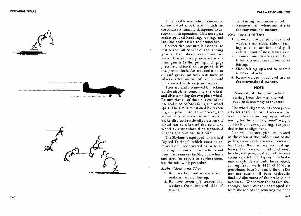
OPERATING DETAILS CARE - RESPONSIBILITIES
The steerable nose wheel is mounted 3. Lift fairing from main wheel.on an air-oil shock strut which in- 4. Remove main wheel and tire incorporates a shimmy dampener to as- the conventional manner.sure smooth operation. This nose gear Nose Wheel And Tires
-,
' makes ground handling, taxiing, and 1. Remove cotter pin, nut and5 landing both easier and smoother.-- washer from either side of fair-
Correct tire ressure is essential to.
P.
ing at axle location, and pull.. . realize the full benefit of the landing axle stud out of nose wheel axle.
- - gear and to obtain maximum tire 2. Remove nut, washers and boltwear. Correct tire pressure for the
. . from top attachment point onmam gear is 28 Ibs. per sq. inch gage . .
pressure and for the nose gear it is 29 fairing.- 3. Slide fairing upward to permitIbs. per sq. inch. An accumulation of
. removal of wheel.oil and grease on tires will have an2dverse effect on tire life and should 4. Remove nose wheel and tire in
be removed with soap and water. the conventional manner.
Tires are e2sily removed by jacking NOTEup the airplane, removing the wheel, Removal of the nose wheeland disassembling the two piece wheel. . . . .
. . fairing from the airplane willBe sure that all of the air is out of the .
. require disassembly of the strut.tire and tube before taking the wheelapart. The tire is reinstalled by revers- The wheel alignment has been prop-ing the procedure. In removing the erly set at the factory. Excessive tirewheel, it is necessary to remove the wear indicates an improper wheelbrake disc anti-rattle clips before the setting for the "on the ground" weightwheel can be taken off the axle. The at which you are operating. See your
--- wheel axie nut should be tightened dealer for re-alignment.finger tight plus one-half turn. The br2ke master cylinders, located
The Skylane is equipped with wheel in the cabin at the rudder and brake"Speed Fairings" which must be re. pedals, incorporate a reserve reservoirmoved or disconnected prior to re- for brake fluid to replace leakagemoving the nose or main wheels and losses. The reservoir Ruid level must
tires. To remove the Skylane wheels be checked periodically, and the res-
and tires for repair or replacement, ervoir kept full at all times. The brakeuse the following procedure: master cylinders should be serviced,
as required, with MIL-O-5606, aMain Wheels And Tires petroleum base hydraulic fluid. (Do
--- 1. Remove bolt and washers from not use castor oil base hydraulicoutboard side of fairing. fluid). Adjustment of the br2ke is not
2. Remove seven (7) screws and necessary. Whenever the brakes feelwashers from inboard side of spongy, bleed out the entrapped airfairing. from the top of the actuating cylinder
6-3
2-6
CARE - RESPONSIBILITIES
(4) Securely tie the middle of a than if it is flown regularly, and shouldlength of rope to ring at tail. be carefully checked over before beingPull each end of rope away at put back into service.45° angle and secure to tie-
down rings positioned on each LIFTING AND JACKING. Illside of tail. The airplane may be lifted by an i:i:i:
(5) Install surface control locks appropriate sling at the engine mount OperCŸmg AGIGlÎSbetween the flap and aileron fuselage attachment fitting and a slingof each wing. around the aft section of the fuselage.
(6) Tie control wheels back with The upper half of the cowl must befront seat beits if control lock removed for application of the sling
.
The following information elaborates on the more importantis not available. at the engine mount fuselage attach- items discussed in the check list on Section II. Not all items in that
(7) Install surface control lock ment fitting. sect10n are covered, as only a few require further discussion.over fin and rudder. Jackingpoint brackets and hoisting
STORAGE rings are available as optional equip-CLEARINGTHE PROPELLER iow maintenance cost.
ment and msure easy, safe handimg ofThe all-metal construction of your the airplane. A block of hardwood "Clearing" the propeller should be- 1. Before Starting - It is advisable
Cessna makes outside storage of it sawed at an angle to fit between the come a habit with every pilot. "LOOK, to make a precautionary ground inspec-practical. Inside storage of the plane fuselage and the main landing gear YELL, AND LISTEN" should be pre- tion of the engine and its controls be-will increase its life just as inside stor- spring may be used as a jacking point starting procedure. "Look" - visually fore starting each day. Visually checkage does for your car. If an airplane to hold the airplane when working on determine that no one is near the pro- the fuel strainer bowl for water ormust remain inactive for a time, clean- a main wheel or tire. Do not use the peller; "Yell" - yelling "CLEAR" in dirt. Pull the fuel strainer drain con-
liness is probably the most important brake casting as a jacking point. loud tones warns anyone from step- trol knob (26, figure 1) and drain aconsideration - whether your airplane To remove the nose wheel, the air- ping into the propeller; "Listen" - small amount of fuel from the fuelis inside or outside. A small invest- plane may be held in a nose high atti- listen for an answering "clear" from strainer. Check for leaks in the fuelment in cleanliness will repay you tude by holding the tail down or by ground personnel reconfirming that supply lines which are visible thru the
many times in not only keeping your placing a padded support under the everyone knows of your intention of cowl access door. (Leaks will beairplane looking like new but in keep- aft end of the nose gear support starting the engine, and that they visible from the dye stains left froming it new. A later paragraph in this forging. Brake or block the main should stand clear- the evaporating fuel).section covers the subject in detail. wheels when the nose wheel is being Inspect the carburetor air filter to
Do not neglect the engine when stor- raised for removal. ENGINE OPERATING determine that it is not restricted bying the airplane. Turn it over by hand LANDINGGEAR, WHEELS, PROCEDURE. dust and other foreign matter.or have it turned over every few days You have a new Continental engine Check for oil leaks visible thru theto keep the bearings, cylinder walls, AND TIRES· made to the highest standards avail. cowl access door. Check for proper oiland internal parts lubricated. Full fuel The main landing gear consists of a able. This engine has been carefully quantity desired.tanks will help prevent condensation single tapered spring leaf for each operating in its run-in and flight tests, If everything is satisfactory, placeand will increase fuel tank life. main gear. This spring is made from so that you receive the engine in its carburetor heat in "cold" position,
Airplanes are built to be used and the highest quality chrome vanadium best possible condition. Proper engine propetter governor control at "Highregular use tends to keep them in steel, heat treated and shot peened for operation will pay rich dividends in RPM" and close throttle.good condition. An airplane left stand- added fatigue resistance. No mainten~ increased engine life. The following 2. Starting Engine - Ordinarily theing idle for any great length of time ance of this spring is necessary other items are important in providing the engine starts easily with one or twois likely to deteriorate more rapidly than paint to prevent rusting maximum trouble-free operation and strokes of primer in warm tempera-
6-24-1
OPERATING DETAIL5
tures to six strokes in cold weather, "both". The maximum allowable mag-with the throttle"In"approximately ½ neto drop is 125 RPM.inch. In extremely cold temperatures If there is any uncertainty in engineit may be necessary to continue prim. operation, a full power run up can being while cranking. Weak intermittent made for short duration. Engine op-explosions followed by puffs of black eration should be smooth, and fullsmoke from the exhaust stack indi. throttle, high engine speed should be care of the airplane -
cates overpriming or flooding. Excess approximately 2550 RPM.fuel can be cleared from the carburet. 4. Take-Off- Most engine wear OWHOf'S FOSpORSibilitiesor chambers by the following proced- occurs from improper operation before
IF YOUR AIRPLANE is to retain that new plane performance,ure: Set the mixture control in "full the engine is up to normal operating
,, stamina, and dependability, certain requirements in its care, inspec-lean" position, throttle full open", temperatures, and operating at high .
ignition switch "Off ", and crank the powers and RPM's. For this reason the tion, and maintenance must be followed. It is always wise to followengine through several revolutions use of maximum power for take-off a planned schedule of lubrication and maintenance based on the cli-
with the starter. Repeat the starting should be limited to that absolutely matic and flying conditions encountered in your locality.procedure without any additional necessary for safety. Whenever pos- Keep in touch with your Cessna dealer and take advantage ofpriming. sible, reduce take-off power to normal his knowledge and experience. He knows your airplane and how to
If engine is underprimed (most climb power- maintain it. He will remind you when lubrications and oil changeslikely in cold weather with a cold 5. Climb -- The same comments are necessary and about other seasonal and periodic services.engine) it will not fire at all, and ad. concerning engine operation duringditional priming will be necessary. "Take-Off " apply to climb at low alti· MOORING YOUR AIR-
As soon as the cylinders begin to tudes where high engine power is GROUND HANDLING.fire open the throttle slightly to keep available. At high altitudes where The airplane is most easily and PLANE. (See figure 20.)it running. relatively low power is obtainable full safely maneuvered, during ground Proper tie-down procedure is your
3. Warm-Up - The engine should throttle operation is permissible if the handling, by the use of a tow-bar best precaution against damage tobe warmed up at approximately 800 engine is warmed up suñiciently- attached to the nose wheel. Always your parked airplane by gusty orRPM for at least one minute in warm Engine speeds above 2450 RPM do use a tow-bar when one is available. strong winds. To tie-down your air-weather and three minutes in cold not increase the rate-of-climb suñi- When moving the airplane by hand plane securely proceed as follows:weather. The remaining warm-up time ciently to off-set the added fuel con- and no tow-bar is available, push (1) Tie sufficiently strong (700can be conducted while taxiing to the sumption and engine wear.encount· down at the front edge of the stabil- pounds tensile strength) ropestake-off position, preferably limiting ered, for normal operations. The max- izer adjacent to the fuselage to raise or chains to the wing tie-down
RPM to 1200 RPM. imum power available should be used the nose wheel off the ground. When fittings located at the upperDuring the pre-take-off check, en- when essential, but should not become the nose wheel is held clear of the end of each wing strut.
gine speeds can be increased to 1700 a normal operating procedure- ground the airplane can be readily (2) Secure the opposite ends ofRPM only long enough to perform 6. Engine Operation During Cruise turned in any direction by pivoting it these ropes or chains to tie-
magneto, propeller, and carburetor - The maximum recommended pow- about the main gear. Do not push down rings suitably anchoredheat checks. The magneto should be er for cruise is 23 inches manifold down on the empennage by the tip of to the ground.switched first to the "L" position, the pressure and 2450 RPM. Greater range the elevator; likewise, do not shove side- (3) Tie a rope or chain thru the tic-
RPM drop noticed and then returned can be obtained at lower power set- wise on the upper portion of the fin. down ring located in the noseto "both" until the speed returns to tings as shown in the range charts When moving the airplane forward gear attachment forging andthe original value. Similarly check (Figure 18). These ranges are based or backwards, push at the wing strut secure the opposite end to a tie-
drop on "R" and switch back to on flight test data with lean mixture root fitting or at the main gear strut. down ring in the ground.
3-2 6- I
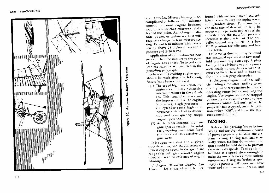
CARE - RESPONSIBILITIESOPERATING DETAILS
¯¯¯
at all altitudes. Mixture leaning is ac. formed with mixture "Rich" and suf-complished as follows: pull mixture ficient power to keep the engine warmcontrol out until engine becomes and cylinders clean. To maintain arough; then enrichen mixture slightly constant rate of descent, it will bebeyond this point. Any change in alti- necessary to periodically reduce thetude, power, or carburetor heat will throttle since the manifold pressurerequire a change in lean mixture set- increases as altitude is lost. The pro-ting. Do not lean mixture with power peller control may be left in a lowsetting above 23 inches of manifold RPM position for efficiency and lowpressure and 2450 RPM. noise level.
Application of full carburetor heat On some let-downs, it may be foundmay enrichen the mixture to the point that continual operation at low mani-of engine roughness. To avoid this, fold pressure may cause spark pluglean the mixture as instructed in the fouling. It is advisable to apply powerpreceding paragraph. occasionally during the descent to in-
Selection of a cruising engine speed crease cylinder heat and to burn oilshould be made after the following from the spark plug electrodes,factors have been considered: 8. Stopping Engine - Allow suffi-
(1) The use of high power with low cient iding time after landing to re-
IllIIllfilllfillillii engine speed results in excessive duce cylinder temperature below theinternal pressure in the cylind- operating range before stopping theers. This condition gives one engine. The engine should be stoppedthe impression that the engine by moving the mixture control to leanis laboring. High pressures in position (control full out). After thethe cylinder cause high tem- propeller has stopped, turn the igni-peratures which lead to detona- tion switch "Off", and leave the mix-tion and consequently rough ture control full out.engine operation.
-9 (2) At the other extreme, high en- TAXIING.gine speeds result in harmful Release the parking brake beforereciprocating and centrifugal
.taxiing and use the minimum amount
strains as well as excessive en-of power necessary to start the air-
gme wear, plane moving. During taxi, and espe-It is suggested that for a given cially when taxiing downwind, the
throttle setting one should select the rpm should be held down to preventlowest engine speed in the green arc excessive taxi speeds. Taxiing shouIdrange that will give smooth engine be done at a speed slow enough tooperation with no evidence of engine make the use of brakes almost entirelylaboring- unnecessary. Using the brakes as spar-
J i II h,._
7. Engine Operation During Let- ingly as possible will prevent undueDown - Let-down should be per- wear and strain on tires, brakes, and
5-8
OPERATING DETAILS OPERATIONAL DATA
landing gear. Normal steering is ac- duce power to 23 inches manifold
complished by applying pressure to pressure and 2450 RPM as soon asthe rudder pedal in the direction the practical to minimize engine wear.
airplane is to be turned. For smaller 2. Use of Wing Flaps for Take-off--radius turns, at slow speed, the brakes The use of 20 degrees wing flaps re-may be used on the inside wheel. At duces the total distance over a 50-footslow taxi speed, this airplane may be obstacle by approximately 20%. Thispivoted about the outboard strut fit- is a result of slower forward speedsting without sliding the tires. When even though, the use of wing flapstaxiing in crosswinds it is important lessens the rate of climb. Therefore,that speed and use of brakes be held for increased take-off performance, theto a minimum and that all controls be recommended technique is to lowerutilized (see taxiing diagrram on page wing flaps 20 degrees (second notch).3-5 ) to maintain directional control It is recommended that the take-offand balance· charts, (figures 16 and 17), be con-
NOTE sulted to determine the distance re-
Caution should be used when quired for take-off. 30 and 40 degreetaxiing over rough fields to avoid wing flaps are not recommended at
excessive loads on the nosewheel. any time for take-off.
Rough use of brakes and power REMEMBERalso add to nosewheel load. A Don't under marginal conditions,good rule of thumb: "Use mini- leave wing flaps on long enough thatmum speed, power, and brakes." you are losing both climb and air-
Taxiing over loose gravel or cinders speed.should be done at low engine speed Don't raise wing flaps with airspeedto avoid abrasion and stone damage to below "off-flaps" stalling speed. (Seethe propeller tips. Full throttle run- stalling speed chart, figure 11.)ups over loose gravel are especially Do slowly release the wing flaps asharmful to propeller tips. When take- soon as you reasonably can after take-
offs must be made over a gravel off, preferably 50 feet or more oversurface, it is very important that the terrain or obstacles.throttle be advanced slowly. This al-lows the airplane to start rolling CLIMB.before high rpm is developed, and Normal climbs are conducted atthe gravel will be blown back of the 100-120 MPH with wing flaps up, 23propeller rather than pulled into it. inches manifold pressure and 2450
RPM. For maximum climb perform-TAKE-OFF• ance use full throttle and 2600 RPM.1. Normal Take-Off- Normal take- The sea level best rate of climb speed
offs are accomplished with wing flaps is 90 MPH, IAS at sea level, and isup, full throttle, and 2600 RPM. Re- reduced ½ MPH for every 1,000 feet3-4
5--7
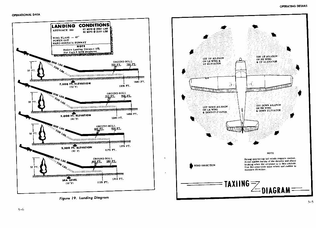
OPERATIONAL DATA OPERATING DETAILS
LANDING CONDITIONSAPPROACH IAS 67 MPH @2650 LBS
60 MPH @2100 LBS
WING FLAPS --40°
POWER OFFHARD SURFACE RUNWAY
NOTEReduce Landing Distance 10%For Each 6 MPH Headwind
GROUND ROLL USE UP AILERON USE UP AILERON555 FT "00 FT, ON LH WING & ON RH WING
50 FT. UP ELEVATOR & UP ELEVATOR
130 FT.
1540 FT.
50
20 OUND ROFL
USE DOWN AILERON USE DOWN AILERONON LH WING ON RH WING
5 FT. ELEVATION 1450 FT• & DOWN ELEVATOR & DOWN ELEVATOR(41 F) 1240 FT.
GROUND ROLL
50 FT
SOO FT. ELEVATION 1375 FT.(50 F) 1175 FT.
GROUND ROLL NOTE445 FT 560 FT,
50 FT Strong quartering tail winds require caution.Avoid sudden bursts of the throttle and sharp
WIND DIRECTION braking when the airplane is in this attitude.Use the steerable nose wheel and rudder tomaintain direction.
SEA LEVEL 1310 FT.(59°F) 1125 FT.
TAXIING-Figure 19. Landing Diagram
5-6
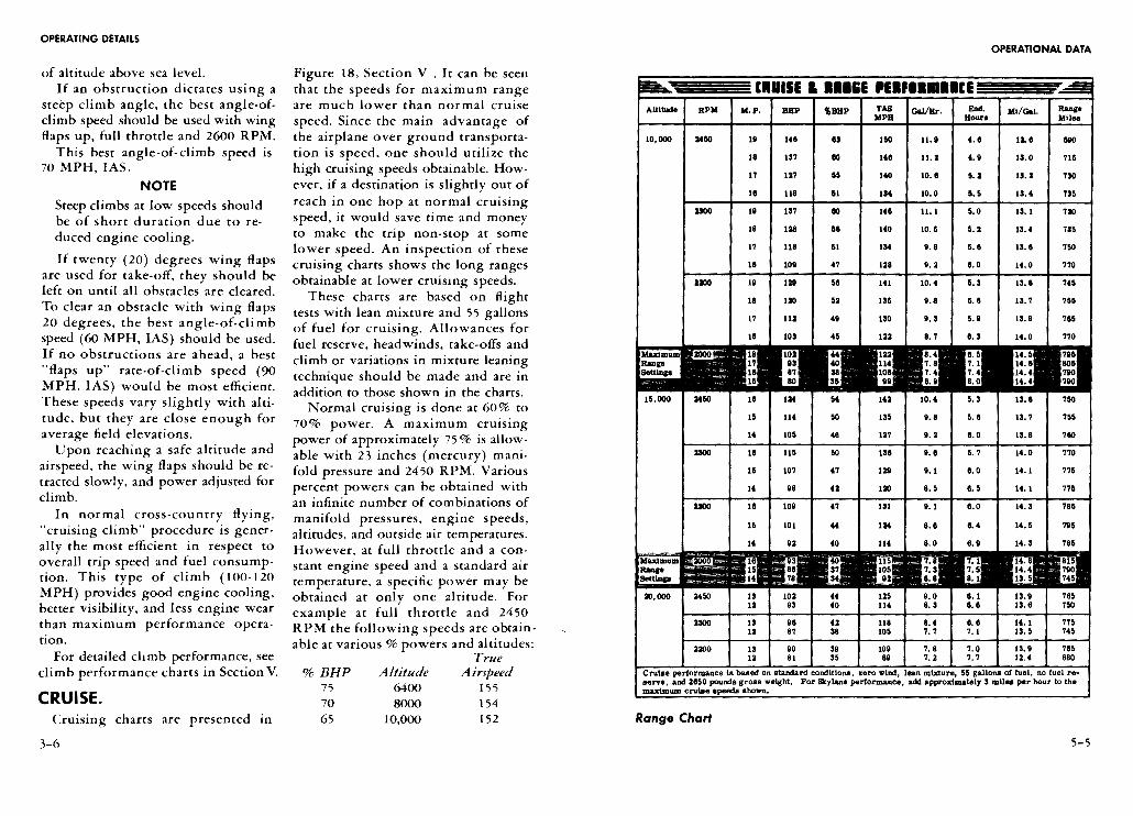
OPERATING DETAILSOPERATIONAL DATA
of altitude above sea level. Figure 18, Section V . It can be seenIf an obstruction dictates using a that the speeds for maximum range --- IBUISEE RESSE PERFORMIRitE
steep climb angle, the best angle-of- are much lower than normal cruise Atuaal• nrx u.P. mar %sur T^s oatiar. =- ulloal.climb speed should be used with wing speed. Since the main advantage of "'" "°"" ""**
flaps up, full throttle and 2600 RPM. the airplane over ground transporta- io,ooo saae is 14e es iso 11., 4.e is.. esoThis best 2ngle-of-climb speed is tion is speed, one should utilize the
70 MPH, IAS. high cruising speeds obtainable. How-NOTE ever, if a destination is slightly out of
Steep climbs at low speeds should reach in one hop at normal cruising
be of short duration due to re. speed, it would save time and money
duced engine cooling. to make the trip non-stop 2t some is ise se tuo io.s s.2 is.a was
lower speed. An inspection of these is its si ist o.a s.e 13.6 Tso
If twenty (20) degrees wing flaps cruising charts shows the long ranges le los 47 isa e.a e.o 14.o vioare used for take-off, they should be obtainable at lower cruising speeds. sano is iso se 141 to.« s.s is.e wasleft on until all obstacles are cleared These charts are based on flight to iso s2 iss e.a s.e 13.7 TesTo clear 2n obst2cle with wing flaps tests with lean mixture and 55 gallons20 degrees, the best angle-of-climb
of fuel for cruising. Allowances forspeed (60 MPH, IAS) should be used fuel reserve, headwinds, take-offs andIf no obstructions are ahead, a best . u.atmum zooo is los 44 122 a.« e.s 14.s Tes
.
climb or variations in mixture leamng a..g. 17 os to ut s.s 9.1 14.s aos'flaps up" rate-of-climb speed (90 technique should be made and are in s.mns. av se i
MPH, IAS) would be most efficient addition to those shown in the charts.These speeds vary slightly with alti- Normal cruising is done at 60% to
is,ooo uso le in se its 10.4 s.s is.e Tso
tude, but they are close enough for 70% power. A maximum cruising* "' °°
average field elevations· power of approximately 75% is allOW- 14 105 46 127 9.2 6.0 13.8 760
Upon reaching a safe altitude and able with 23 inches (mercury) mani. asoo is us so ase e.e s.7 14.o Tao
airspeed, the wing flaps should be re- fold pressure and 2450 RPM. Various is lov 42 12e ».1 a.o 14.1 776
tracted slowly, and power adjusted for percent powers can be obtained with 14 98 42 120 8.5 6.5. 14.1 770climb an infinite number of combinations of 2,,, 2, go, 4, 22, ,,, s.o 24.2 gas
In normal cross-country flying, manifold pressures, engine speeds,is ici sa iss e.e e.4 14.5 vos
cruising climb procedure is gener- altitudes, and outside air temperatures.ally the most efficient in respect to However, at full throttle and a con-overall trip speed and fuel consump- stant engine speed and a standard air .... o ao a
tion. This type of climb (100-120 temperature, a specific power may be s.eu... 14 is se es e.s s.: is.s was
MPH) provides good engine cooling, obtained at only one altitude. For so,ooo 24so la io2 44 125 e.o 6.1 13.9 Tes
better visibility, and less engine wear example at full throttle and 2450is sa ao 114 a.: e.e is.e Too
than maximum performance opera- RPM the following speeds 2re obtain-,
3° " M 'n' M O u i m
tion· able at various % powers 2nd 21titudes: 2,,, ,, ,, ,, , ,,, ,.,For detailed climb performance, see True la si as •• 7.2 7.7 12 sao
climb performance charts in Section V. % BHP Altitude Airspeed Crutse performance is based on standard condinons, sero wind, lean mixture, 55 gaHons of fuel, no fuel re-serve, and 2650 pounds gross weight. For Skylane performance, add approximately 3 miles per hour to the
75 6400 I 55 maximum cruise speeds shown.CRUISE. yo sooo is4
Cruising charts are presented in 65 10,000 152 Range Chart
5-53-6
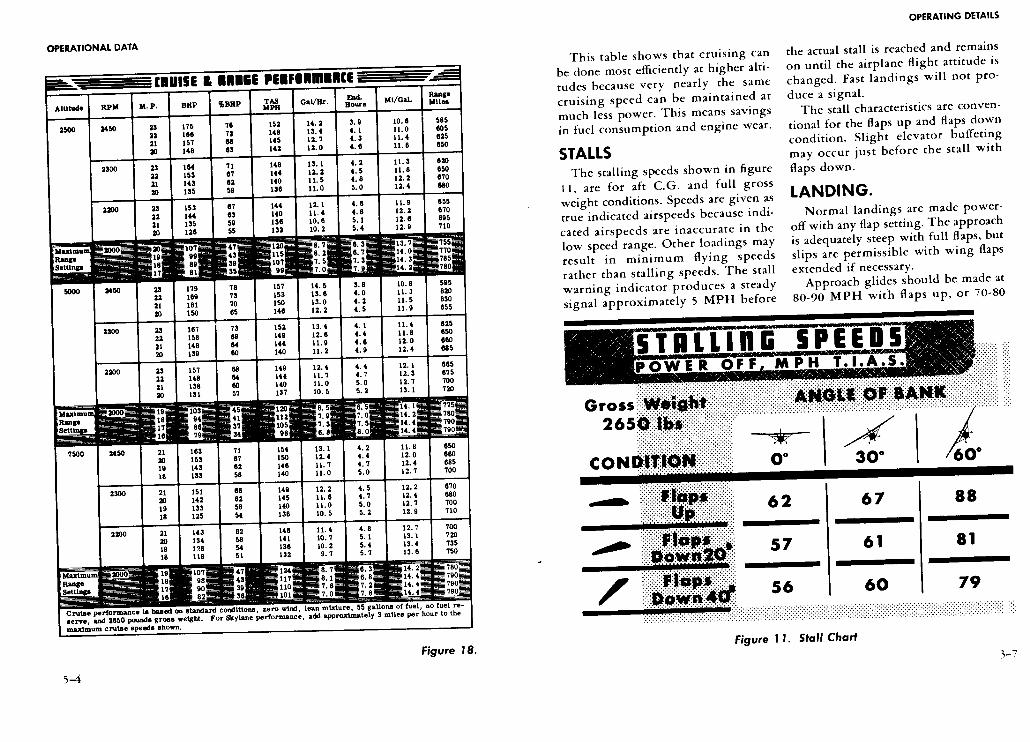
OPERATING DETAILSOPERATIONAL DATA
This table shows that cruising can the actual stall is reached and remains
a (8815E & 5586E PERFORIRRREE be done most efficiently at higher alti- on until the airplane flight attitude is
End. Range tudes because very nearly the same changed. Fast landings will not pro-Altitude RPM M. P. BHP %BBP TAS Gal/Br. Ml/Gal. . .uma sour. uti.. cruising speed can be maintained at duce a signal.asoo asso 2s iss ze 152 14.2 s.s 10.6 ses much less power. This means savings The stall characteristics are conven-
22 ISS 72 148 13.4 4,1 11.0 005 .
21 157 68 145 12.7 4,3 11.4 625 In fUCI COnsumption and engine wear, tional for the flaps up and flaps downæ its es 142 12.o 4,e 11.8 eso condition. Slight elevator buffeting
2300 23 164 11 148 13.1 4.2 11.3 6. STALLS may occur ust before the stall with22 153 07 144 12.2 4.5 11.8 85021 143 02 140 11.5 4.8 12.2 670 The stalling speeds shown in figure flaps down.20 135 59 136 11.0 5.0 12.4 680
11, are for aft C.G. and full gross2200 23 153 67 144 12.1 4.8 11.9 655 LANDING
22 144 63 140 11.4 4.8 12.2 670 WC1ght conditions. Speeds are given as •
* 1Ë$ ËÎ 'sÎ 16
52 6 6 | true indicated airspeeds because indi- Normal landings are made power-
Maxim WOD 20 107 47 120 8.7 6.3 13.7 755cated airspeeds are inaccurate in the off with any flap setting. The approach
Range 19 99 43 115 8.2 6.7 14.0 770 IOW Speed range. Other loadings may is adequately steep with full flaps, butSettings 18 89 39 107 7. 5 7. 3 14. 3 785 - . .
17 81 35 99 7.0 7.9 14.2 780 f€$Ulf In In1H1fDUIn flying speeds slips are permissible with wing flaps5000 3450 23 179 T8 157 14.5 3.8 10.8 595 rather than stalling speeds. The stall extended if necessary.
$Ì ÌÊÎ $$ Ì°s$ ÌÌo Î ÌÌ:Ë is2 warning indicator produces a steady Approach glides should be made at20 150 65 146 12.2 4.5 11.9 855 signal approximately 5 MPH before 80-90 MPH with flaps up, or 70-80
2300 23 167 73 152 13. 4 4. 1 11. 4 625
!! !!! !! !!! !!:i lii l'! !!! STRLL 18 6 5 PEEDS2200 23 157 68 149 12. 4 4. 4 12. 1 885
22 148 84 144 11.7 4.7 12.3 67521 138 00 140 11.0 5.0 12.7 70020 131 57 137 10.5 5.2 13.1 720
\¾" "°° i 2¾¾ ¾i !!°2 ::: i:¾ 11:1 ligg Gross Weight ANOki E NAMESett 17 86 37 105 7.3 7.5 14.4 7902
10 79 34 98 6.8 8.0 14.4 790
7500 3450 21 163 71 154 13.1 4.2 11.8 85020 153 67 150 12. 4 4. 4 12. 0 660
li l'i la' l'o' 11: ':I li:' !¾ CONOlflÔN 0° 30° 0°2300 21 151 66 149 12. 2 4. 5 12. 2 670
20 142 62 145 11.6 4.7 12.4 680
2200 21 143 62 146 11,4 4.8 12.7 70020 134 58 141 10. 7 5. 1 13. 1 72019 126 54 136 10,2 5.4 13.4 73518 118 51 132 9,7 5.7 13.6 750 a 57 61 81Down O
Settings 17 90 39 110 7, 6 7. 2 14. 4 790-- 16 82 38 101 7.0 7.8 14.4 790
Cruise performance is based on standard conditions, zero wind, lean mixture, 55 gallons of fuel, no fuel re-serve, and 2650 pounds grose weight. For Skylane performance, add approximately 3 miles per hour to the
.
maximum cruise speeds shown.
Figure 18. Figure 11. Stali Chart
5-4
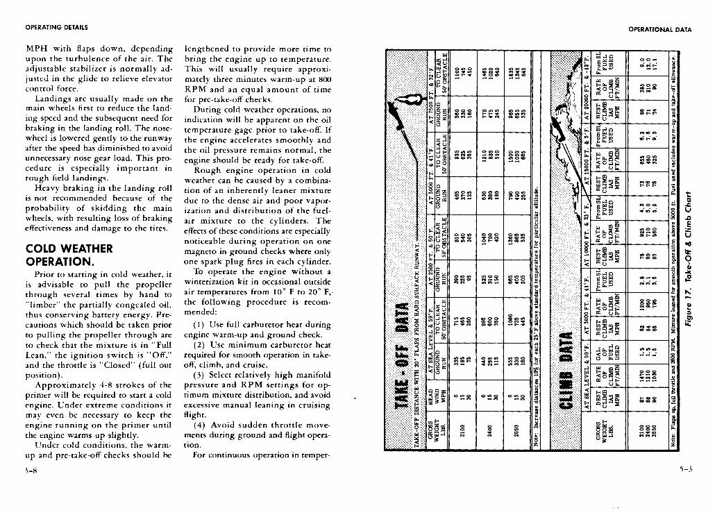
OPERATING DETAILS OPERATIONAL DATA
MPH with flaps down, depending lengthened to provide more time toupon the turbulence of the air. The bring the engine up to temperature. gi y 00 oo- 6adjustable stabilizer is normally ad- This will usually require approxi- 6 did :::justed in the glide to relieve elevator mately three minutes warm-up at 800control force. RPM and an equal amount of time
Landings are usually made on the for pre-take-off checks.main wheels first to reduce the land- During cold weather operations, noing speed and the subsequent need for indication will be apparent on the oilbraking in the landing roll. The nose- temperature gage prior to take-off. Ifwheel is lowered gently to the runway the engine accelerates smoothly andafter the speed has diminished to avoid the oil pressure remains normal, theunnecessary nose gear load. This pro- engine should be ready for take-off.cedure is especially important in Rough engine operation in cold ------- 2rough field landings- weather can be caused by a combina-
Heavy braking in the landing roll tion of an inherently leaner mixtureis not recommended because of the due to the dense air and poor vapor-probability of skidding the main ization and distribution of the fuel-wheels, with resulting loss of braking air mixture to the cylinders. The Eeffectiveness and damage to the tires effects of these conditions are especially 2 g
noticeable during operation on one 8 4COLD WEATHER magneto in ground checks where only tt:
OPERATION. one spark plug fires in each cylinder.
Prior to starting in cold weather, it To operate the engine without a
is advisable to pull the propeller winterization kit in occasional outside
through several times by hand to air temperatures from 10° F to 20° F,-
"limber" the partially congealed oil, the following procedure is recom-
thus conserving battery energy. Pre- mended: ..
cautions which should be taken prior (1) Use full carburetor heat duringto pulling the propeller through are engine warm-up and ground check. sigto check that the mixture is in "Full (2) Use minimum carburetor heatLean," the ignition switch is "OfT," required for smooth operation in take-
and the throttle is "Closed" (full out off, climb, and cruise.position). (3) Select relatively high manifold
Approximatelv 4-8 strokes of the pressure and RPM settings for op-
primer will be required to start a cold timum mixture distribution, and avoidengine. Under extreme conditions it excessive manual leaning in cruising i 4..¾may even be necessary to keep the flight.engine running on the primer until (4) Avoid sudden throttle move- ggthe engine warms up slightly. ments during ground and flight opera- = =
Under cold conditions, the warm- tion.
up and pre-take-off checks should be For continuous operation in temper-
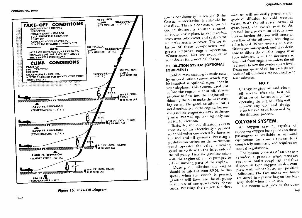
OPERATIONAL DATA OPERATING DETAILS
eo rT,/urN. atures consistently below 20° F the minutes will normally provide ade-TAKE-OFF CONDITIONS CL
MPH IAS F Cessna winterization kit should be quate oil dilution for cold weatherACE RUNWAY installed. This kit consists of an oil starts. With the oil at its normal 12
GROSS WEIGRT - 2650 LBS cooler shutter, 2 shutter control, quart level, the switch may be de-FULL 'ITIROTTLE & 2600 RPM .
FLAPS 2o• oil cooler cover plate, intake manifold pressed for a maximum of four min-PLHANESACCCE TESOMTACLE cross-over tube cover and carburetor utes - further dilution will cause an
ggggg 325 FT./MIN. air intake restrictor cover. The instal- overflow of the oil sump, resulting inINCREASE DISTANCE TO CLEAR 50 FT. CLIMB 15,000 FT· lation of these components will a fire hazard. When severely cold con-°WETAC
EREEACH F ABOVE @78 MPH IAS (5 F.) greatly improve engine operation. ditions are anticipated, and it is desir-
/ Winterization kits are available at able to dilute the oil for longer thanCLIMB CONDITIONS your dealer for a nominal charge. four minutes, it will be necessary to
' " drain oil from engine - unless the oilFULL WROTTLE OIL DILUTION SYSTEM (OPTIONAL -seoo apu 560 FT./MIN 1s already below the twelve quart level.GROSS WEIGHT - 2650 LBs. EOUIPMENT) -
MIXTURE LEANED FOR SMOGIll OPERATION FL8
MPH IAS -
Dram one quart of oil for each 90 sec-ABOVE 5000 FT. Cold climate starting is made easier onds of oil dilution time required over
by an oil dilution system which may four minutes.be installed as optional equipment inyour airplane. This system, used just NOTE
50 FT.680 FT./MIN. before the engine is shut off, allows Change engine oil and clean
A965 FT., A1835 FT. / 8 MPR IAS
g2SOÎÏOC TO ÍlOw into the engine oil - oil screens after the first oilthinning the oil to make the next start- dilution of the season before
7,soo FT. ELEVATION . .
(TEMPERATURE -
32° F.) ing easier. The gasoline-diluted oil is operating the engine. This will
not deteriorative to the engine, because remove any dirt and sludge
50FTthe gasoline evaporates away as the en- which have been loosened by
195 FT./MIN. CLIMB gine is warmed up, leaving only the the dilution process.AGO FT. ×1500 FT. / @88 MPH IAS oil for lubrication.
s, o FT. souvArioN Basically, the oil dilution system OXYGEN SYSTEM.(TEMPERATURE -
41° F.) consists of an electrically-operated An oxygen system, capable of
solenoid valve connected by hoses to supplying oxygen for a pilot and three
sort. the fuel and oil systems. Pressing a passengers is available as optional910 FT./M[N. CLIMB push-button switch on the instrument equipment for your airplane. It is
A1260 FT· X @88 MPH IAs panel operates the valve, allowing completely automatic and requires no2,soo FT. ELEVATION gasoline to flow to the inlet side of manual regulations.
(TEMPERATURE - 50 F.) the oil pump. Here the gasoline mixes The system consists of an oxygenwith the engine oil and is pumped to cylinder, a pressure gage, pressure
50 FT. - all the moving parts of the engine. regulator, outlet couplings, and four030 FT /W. CUMB During oil dilution the engine disposable type oxygen masks, com-
should be idled at 1000 RPM. At this plete with rubber hoses and positionSEA LEVEL
(TEMPERATURE - 59°F.) speed, when the switch is pressed, indicators. The face masks and hosesgasoline will flow into the oil pump are stored in a plastic bag on the bag-at the rate of one quart every 90 sec- gage shelf when not in use.
Figure 16. Toke-OH Diogrom onds. Pressing the switch for three The system will provide the dura-5--2
3-9
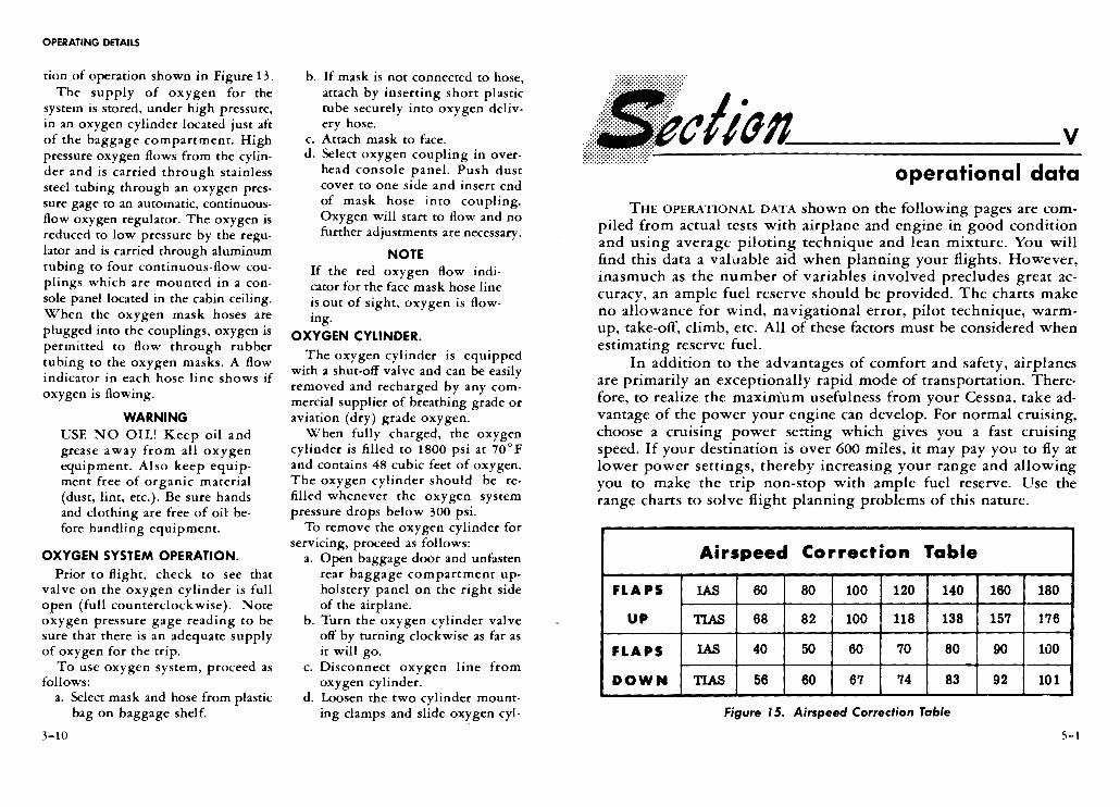
oPERATING DETAILS
tion of operation shown in Figure 13. b. If mask is not connected to hose, :::÷::::::::::
The supply of oxygen for the attach by inserting short plasticsystem is stored, under high pressure, tube securely into oxygen deliv-in an oxygen cylinder located just aft ery hose.of the baggage compartment. High c. Attach mask to face.pressure oxygen flows from the cylin- d. Select oxygen coupling in over- :g;;
der and is carried through stainless head console panel. Push dust operational datasteel tubing through an oxygen pres. cover to one side and insert endsure gage to an automatic, continuous. of mask hose into coupling.
THE OPERATIONAL DATA shown on the following pages are com-flow oxygen regulator. The oxygen is Oxygen will start to flow and no .
fu h a piled from actu21 tests with airplane and engine in good conditionreduced to low pressure by the regu. rt er a justments are necessary.
and using average piloting technique and lean mixture. You willlator and is carried through aluminum NOTE ·find this data a valuable aid when planning your flights. However,tubing to four continuous-flow cou- If the red oxygen flow indi-plings which are mounted in a con- cator for the face mask hose line
inasmuch as the number of variables involved precludes great ac-
sole panel located in the cabin ceiling· is out of sight, oxygen is flow- curacy, an ample fuel reserve should be provided. The charts makeWhen the oxygen mask hoses are ing no allowance for wind, navigational error, pilot technique, warm-plugged into the couplings, Oxygen is OXYGEN CYLINDER. up, take-off, climb, etc. All of these factors must be considered whenpermitted to flow through rubber estimating reserve fuel.tubing to the oxygen masks. A flow The oxygen cylinder is equipped In addition to the advanta es of comfort and safet , air lanes
. with a shut-off valve and can be easilyindicator in each hose line shows ifremoved and recharged by 2ny com- 2re primarily an exceptionally rapid mode of transportation. There-
oxygen is flowing.mercial supplier of breathing grade or fore, to realize the maximum usefulness from your Cessna, take ad-
WARNING aviation (dry) grade oxygen. vantage of the power your engine can develop. For normal cruising,USE NO OIL! Keep oil and When fully charged, the oxygen choose a cruising power setting which gives you a fast cruisinggrease away from all oxygen cylinder is filled to 1800 psi at 70°F speed. If your destination is over 600 miles, it may pay you to fly atequipment. Also keep equip. and contains 48 cubic feet of oxygen. lower power settings, thereby increasing your range and allowingment free of organic material The oxygen cylinder should be re- you to make the trip non-stop with ample fuel reserve. Use the(dust, lint, etc.). Be sure hands filled whenever the oxygen system range charts to solve flight planning problems of this nature.and clothing are free of oil be. pressure drops below 300 psi.fore handling equipment. To remove the oxygen cylinder for
servicing, proceed as follows: . .
OXYGEN SYSTEM OPERATION- a. Open baggage door and unfasten Aarspeed Correcison TablePrior to flight, check to see that rear baggage compartment up-
valve on the oxygen cylinder is full holstery panel on the right side FLAPS IAS 60 80 100 120 140 160 180open (full counterclockwise). Note of the airplane.oxygen pressure gage reading to be b. Turn the oxygen cylinder valve - UP TIAS 68 82 100 118 138 157 176sure that there is an adequate supply off by turning clockwise as far asofoxygenforthetrip. itwillgo. FLAPS IAS 40 50 60 70 80 90100
To use oxygen system, proceed as c. Disconnect oxygen line fromfollows: oxygen cylinder. DOWN TIAS 56 60 67 74 83 92 101
a. Select mask and hose from plastic d. Loosen the two cylinder mount-bag on baggage shelf. ing clamps and slide oxygen cyl- Fígure 15. Airspeed Correction Tobia
3-10 -
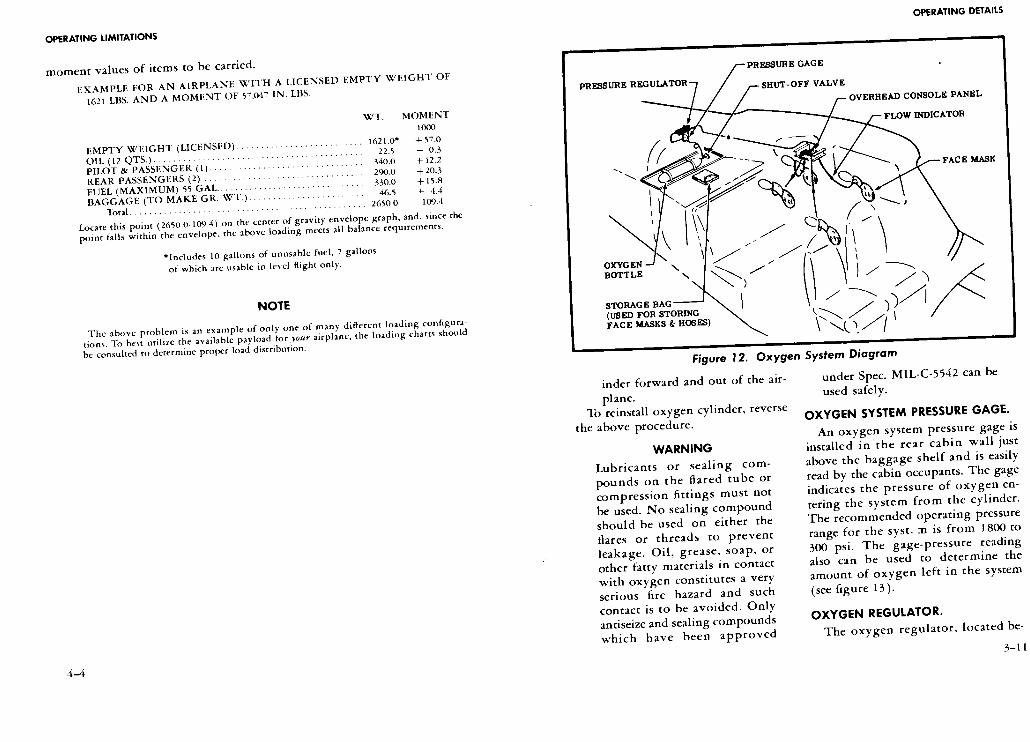
OPERATING LIMITATIONS OPERATING DETAILS
moment values of items to be carried.
EXAMPLE FOR AN AIRPLANE WITH A LICENSED EMPTY WEIGHT OF PRESSURE GAGE
1621 LBS. AND A MOMENT OF 53,047 IN. LBS. PRESSURE RECULATOR SHUT-OFF VALVE
WT. MOMENT OVERHEAD CONSOLE PANEL1000 FLOW INDICATOR
EMPTY WEIGHT (LICENSED)... .
1621.0* +57.0OIL(12QTS.)............., .. . . ....,.. 22.5 - 0.3PILOT & PASSENGER (1)...... .... .. ......... 340.0 +12.2REAR PASSENGERS (2) . . . . . . . . . . . . . . . . , . . . . 290,0 + 20.3FUEL (MAXIMUM) 55 GAL.. . . . . . . . . . . . . . . . . . . . 330.0 + 15.8 " FACE MASKBAGGAGE (TO MAKE GR. WT.) . . . . . . . . . . . . . . . . , . 46,5 + 4.4
Total.................. ...,........ ................. 2650.0 109.4
Locate this point (2650.0-109.4) on the center of gravity envelope graph, and, since thepoint falls within the envelope, the above loading meets all balance requirements.
*Includes 10 gallons of unusable fuel, 7 gallonsof which are usable in level flight only.
OXYGENBOTTLE
NOTESTORACE BAC
The above problem is an example of only one of many different loading configura- (USED FOR STORINGtions. To best utilize the available payload for your airplane, the loading charts should FACE MASKS & HOSES)be consulted to determine proper load distribution.
Figure 12. Oxygen System Diagram
inder Eorward and out of the air- under Spec. MIL-C-5542 can beplane. used safely.
To reinstall oxygen cylinder, reverseOXYGEN SYSTEM PRESSUREGAGE.the above procedure.
An oxygen system pressure gage isWARNING installed in the rear cabin wall just
Lubricants or sealing com- above the baggage shelf and is easilypounds on the flared tube or read by the cabin occupants. The gagecompression fittings must not indicates the pressure of oxygen en-be used. No sealing compound tering the system from the cylinder.should be used on either the The recommended operating pressureflares or threads to prevent range for the syst n is from 1800 toleakage. Oil, grease, soap, or 300 psi. The gage-pressure readingother fatty materials in contact also can be used to determine thewith oxygen constitutes a very amount of oxygen left in the systemserious fire hazard and such (see figure 13).contact is to be avoided. Onlyantiseize and sealing compounds OXYGEN REGULATOR.which have been approved The oxygen regulator, located be-
4-4 3-11
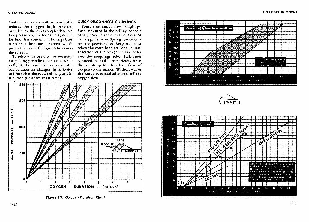
OPERATING DETAILS OPERATINGLIMITATIONS
hind the rear cabin wall, automatically QUICK DISCONNECT COUPUNGS.reduces the oxygen high pressure, Four, continuous-flow couplings,supplied by the oxygen cylinder, to a Rush mounted in the ceiling consolelow pressure of practical magnitude panel, provide individual outlets forfor line distribution. The regulator the oxygen system. Spring loaded cov-contains a fine mesh screen which ers are provided to keep out dustprevents entry of foreign particles into when the couplings are not in use.the system. Insertion of the oxygen mask hoses
To relieve the users of the necessity into the couplings effect leak-prooffor making periodic adjustments while connections and automatically openin ßight, the regulator automatically the couplings to allow free flow ofcompensates for changes in altitudes oxygen to the masks. Withdrawal ofand furnishes the required oxygen dis- the hoses automatically cuts off thetribution pressures at all times. oxygen ßow.
1800
CODE
50040
30
20
01234567 OilOXYGEN DURATION - (HOURS)
Figure 13. Oxygen Duration Chart3--12 4-3
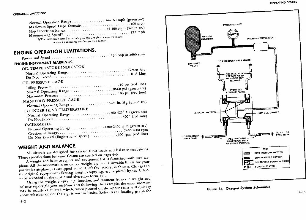
OPERATING UMITATIONS OPERATING DETAILS
Normal Operation Range. . . . . . . . . . . . . . . . . ..64-160 mph (greenarc)
Maximum Speed Flaps Extended . . . . . . . . . . . . . . . . . . . . . . . . .100 mphFlap Operation Range . . . . . . . . . . . . . . . . . . . . .
.55-100 mph (white arc) PRESSURE GAGE
Maneuvering Speed*.................... ..............122 mph
*(The m2ximum speed 2t which you can use abrupt control travelwithout exceeding the design load f2ctor.) oXYGEN
CYLINDER PRESSURE REGULATOR
ENGINE OPERATION UMITATIONS.Power and Speed............ . ...........230 bhp at 2600 rpm
ENGINE INSTRUMENT MARKINGS.OIL TEMPERATURE INDICATOR SHUT-OFF TO PASSENGER FACE MABKS
Normal Operating Range. . . . . . . . . . . . . . . . . . . . . . . . Green ArcDo Not Exceed............ ...........Red Line
RED INDICATOROIL PRESSURE GAGE APPEARS WHEN
OXYGEN IS NOTIdling Pressure. . . . . . . . . . . . . . . . . . . . . . . . . 10 psi (red line) F£4WING
Normal Operating Range . . . . . . . . . - . . . . . . . . . . . . .
30-60 psi (greenarc)Maximum Pressure . . . . . . . . . . . . . . . . . . . . . . .100 psi (red line) OVERHEAD
CONSOLE PANELMANIFOLD PRESSURE GAGE
Normal Operating Range . . . . . . . . . . . . . . . . . . . .15-23 in. Hg (greenarc)
CYLINDER HEAD TEMPERATURENormal Operating Range. . . . . . . . . . . . . . . . . . . . . .
300-425° F (greenarc)Do Not Exceed. . . . . . . . . . . . . . . . . . . . . . .
500° (red line) ""DIA. ORIFICE.023" DIA. ORIFICE
TACHOMETERNormal Operating Range . . . . . . . . . . . . . . . . .
.2200-2450 rpm (greenarc)Cautionary Range................. . ...........2450-2600rpm
Do Not Exceed (Engine rated speed) . . . . . . . . . . . . . .2600 rpm (red line)TO PASSENGER TO PI I'S
FACE MASK FACE MASK
WEIGHT AND BALANCE. DRED AICSA HnEN
OXYGEN Is FLOWING
All aircraft are designed for certain limit loads and balance conditions.These specifications for your Cessna are charted on page 4-3. (00E
A weight and balance report and equipment list is furnished with each air- HIGH PRESSURE OXYGEN
plane. All the information on empty weight c.g. and allowable limits for your -um LOWPRESSUREOXYGEN
particular airplane, as equipped when it left the factory, is shown. Changes in CONTINUOUS FLOW COUPLING
the original equipment affecting weight empty c.g. are required by the C.A.A. FLOW INDICATOR
to be recorded in the repair and alteration form 337.Using the weight empty, c.g. location, and moment from the weight and
balance report foryour airplane and following the example, the exact momentmay be readily calculated which, when plotted on the upper chart will quicklyshow whether or not the c.g. is within limits. Refer to the loading graph for Figure 14. Oxygen System Schematic4-2 3-13
OPERATINGDETAILS
The oxygen rate-of-flow to the user identification and reuse it many times. !!!!!!!is determined by an orifice installed in The face mask receives oxygenthe inlet side of each coupling. The through a rubber tube into the re-
passenger coupling orifices are .016 breather bag. On exhalation, the firstinch diameter and the pilot coupling air exhaled (which is rich in oxygen -
.
orifice is .023 inch diameter. The .023 because it never reaches the lungs) is -i: :!:i: . . . .
inch diameter orifice provides approx- exhaled into the bag, combining with OperCŸmg IlmiŸOŸlOn5imately double the rate-of-flow as that the oxygen. As soon as the bag isdelivered through the .016 inch diam- filled, the remainder of the exhaledeter orifices. The larger rate-of-flow breath (which is low in oxygen, be OPERATIONSAUTHORIZED.is provided primarily for the pilot, cause it has been in the lungs) is ex-but can be used for any of the cabin haled to the atmosphere through Your Cessna with standard equipment as certificated under CAA Typeoccupants who desire additional oxy- upper sides of the bag. Certificate No. 3A13 is approved for day and night operation under VFR.gen. On inhalation, the user inhales the Additional optional equipment is available to increase its utility and to
FACE MASKS.oxygen-enriched contents of the bag. make it authorized for use under IFR day and night. When operated for hire at
.When the bag is emptied, air is drawn night, certificated flares are required. An owner of a properly equipped Cessna
The face masks used with the oxy-through the upper sides of the mask is eligible to obtain approval for its operation on single engine scheduled air-
gen system are of the disposable par-to finish satisfying the inhalation vol- line service on VFR.
tial-rebreathing type and are stored in ume of the user. Additional masks area plastic bag on the baggage shelf. The available at Cessna dealers. MANEUVERS- NORMAL CATEGORY.face masks have the advantage of low
OXYGEN FLOW INDICATOR The airplane exceeds the requirements of the Civil Air Regulations,cost, feather lightness, comfort and the Part 3, set forth by the United States Government for airworthiness. Spins andelimination of the necessity of clean- An oxygen flow indicator is pro-
. . . aerobatic maficuvers are not permitted in normal category airplanes in com-ing and sterilizing. Their users can vided in each face mask hose line. It .
. . pliance with these regulations. In connection with the foregomg, the followingcarry on normal conversations includ- provides visual proof of oxygen flow .
. gross weights and flight load factors apply:ing normal use of the microphone. and operates in any position. A red in-
The masks are durable and the fre- dicator disappears when oxygen is Gross Weight. . . . . . . . . . . . . . . . . . . . . . . 2650 lbs.quent user can mark his mask for flowing. Flight Inad Factor* Flaps Up. . . . . . . . . . . . . . . . . . . . . + 3.8 - 1.52
Flight Load Factor* Flaps Down . . . . . . . . . . . . . . . . . . + 3.5*The design load factors are 150% of the above and in all cases the structure meets or exceeds design
loads.
Your airplane must be operated in accordance with all CAA approvedmarkings, placards and check lists in the airplane. If there is any informationin this section which contr2dicts the CAA approved markings, placards andcheck lists, it is to be disregarded.
AIRSPEED LIMITATIONS.The following are the certificated true indicated airspeed limits:
Never Exceed (Glide or dive, smooth air). . . . . . . . .184 mph (red line)Caution Range. . . . . . . . . . . . . . . . . . . . . . . . . . .
160-184 mph (yellow arc)Maximum Structural Cruising Speed . . . . . . . . . . . . . . . . . . . . . .160 mph
(kvel flight or climb)
3-14 4-1