Embed Size (px)
Citation preview
CERVICAL SPINE SEGMENT FINITE ELEMENT MODEL VALIDATION AND VERIFICATION AT TRAUMATIC LOADING
LEVELS FOR INJURY PREDICTION Jennifer A. DeWit, Duane S. Cronin
University of Waterloo, Mechanical Engineering, Waterloo, Ontario, Canada
ABSTRACT The objective of this study was to verify and validate an enhanced cervical spine segment finite element model to predict tissue-level failure under tension and compression loading. The predicted failure locations were representative of reported cervical spine injuries, and the predicted peak failure forces were within the reported experimental corridors. The displacement to failure of the tension simulation was lower than expected, attributed to limitations in the constitutive model. This study provides a validated approach to predict tissue-level failure for cervical spine segments, predicting the location and sequence of tissue failure, and can be applied to full cervical spine models for the prediction of injurious loading in automotive crash scenarios. Keywords: Finite Element Method, Spine, Injury, Validation INJURIES TO THE CERVICAL SPINE are often associated with a high risk of disability or fatality. This study focused on mechanisms associated with high risk cervical spine injuries and used numerical simulation at the segment level to predict injury to the local tissues. Etiological studies and reviews indicate that the majority of cervical spine injuries occur in automotive collisions, with the highest incidences of injuries occurring at the upper and lower segments of the cervical spine (Cusik and Yoganadan, 2002). It should be noted that, while whiplash is an injury commonly associated with automotive collisions, it was not considered for this study based on the associated low risk of neurological impairment. The type of injury incurred depends on the applied loading scenario. Upper segment injuries are directly related to the direction of skull contact forces at the skull-atlanto-occipital junction while lower segment injuries are caused by forces directly applied to the vertebral body or through a lever arm of several adjacent segments (Cusik and Yoganadan, 2002). Similar conclusions were reached in studies by Robertson et al. (2002), and Daffner et al. (2006) showing a distribution of fractures at each vertebral level with the majority of fractures occurring in the upper and lower segments. Yoganandan et al. (1989b) conducted a clinical study to determine most commonly injured anatomical level during motor vehicle accidents and relate injury locations to the level of impairment. The findings from this study showed that the injuries to the lower cervical spine had the highest level of complete and incomplete quadriplegia, specifically at the C5-C6 segment level. Additional studies by Burney et al., (1993), Myers et al., (1994), and Riggins et al., (1977) also recognized that vertebral fractures have a high probability of leading to significant neurological impairment. The injuries most common at this segment level are compression-flexion injuries and burst (comminuted) fractures of the vertebral bodies. In a similar review study of trauma cases by Argenson et al. (1997), it was found that 33% of the trauma cases were compression injuries, 28% were flexion extension injuries, and 39% were rotation injuries. It should be noted that although rotation injuries are of high frequency they are generally associated with the lowest severity. Of the rotation injuries, 51% were considered the least severe (unifacet fracture) based on injury mechanism, whereas 70% of the compressive injuries were considered to be the most severe (tear-drop fracture) based on mechanism. Also, 50% of the flexion-extension injuries were among the second most severe injury type (severe sprain). Tension loading scenarios such as airbag deployment could result in a load to the cervical spine in out-of-position occupants resulting in serious injury (Blacksin, 1993; Traynelis and Gold, 1993; Kleinberger and Summers, 1997; Sato and Kondo, 2002). The objective of this study was to investigate cervical spine injury mechanisms using a spine segment numerical model. The majority of numerical simulations regarding the cervical spine have been confined to quasi-static simulations to investigate the load-sharing behavior of local tissue (Kumaresan et al., 1997; Teo and Ng, 2001; Ng et al., 2004; Panzer and Cronin, 2009). A small number of studies have used numerical simulations of full cervical spines to evaluate occupant injury
IRCOBI Conference - Hanover (Germany) - September 2010 59
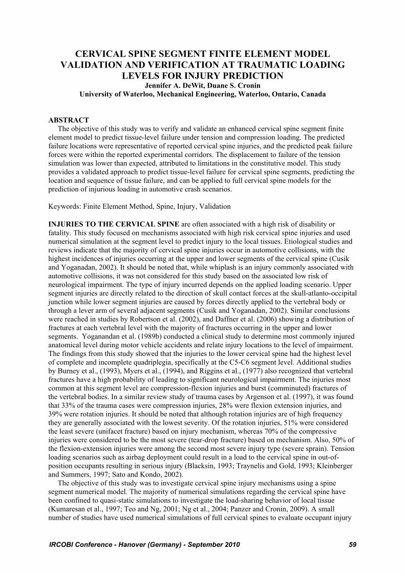
risk during automotive collisions (Halldin et al., 2000 and Meyer et al., 2004), but these studies have been limited in their ability to predict injury. To predict injury, it is important that the model be as biofidelic as possible and must include accurate geometry and material properties, as well as a variety of experimental data to verify and validate the model against. The cases considered in this study included direct tensile and compressive loading to evaluate soft and hard tissue failure. Segment testing to failure under tensile loading was reported in an experimental study by Dibb et al. (2009). For their experiment, they used single segments mounted to an apparatus that pulled the segment in tension from the bottom vertebra. The apparatus maintained the lordotic orientation of the segment to represent in vivo conditions. The segment was loaded at a rate of 1000 N/s with free end conditions to the superior vertebral body. This resulted in a mean failure force (±SD) of 1700N±199N. Compressive loading to failure was carried out in an experimental study conducted by Carter et al. (2002). Function spinal units (FSU) containing three vertebral bodies and two intact discs were mounted to a fixture and compressed. In this study, both the superior and inferior vertebral bodies were subject to fixed end conditions. The FSU was initially preloaded to a level of 40N to represent the load of the head and then was loaded by a ram displacement of between 8mm and 15mm over a 16ms pulse length. Mean compressive force at failure was 3260.9N with a 95% confidence interval of 707.7N. The failure force was measured using a load cell at the centroid of the inferior intervertebral disc. METHODS An existing cervical spine segment model previously validated and verified was used for the simulations in this study. The existing model was validated and verified under physiologic loads (Panzer and Cronin, 2009), in frontal impact (Panzer, 2006), and in rear impact (Fice, 2009). The model included a detailed disc (modeled using solid and shell elements), ligaments (modeled using truss elements) and the vertebral bodies (modeled using solid and shell elements) with an average overall mesh size of 1mm (Fig. 1). Simulations were run using LS-DYNA version 971 R3.1 using single precision calculations on a Linux workstation. The tension model contained 15829 nodes and 22700 elements with a simulation time of approximately 6 hours using six 2.1GHz processors. The compression model contained 32147 nodes and 46599 elements with a simulation time of approximately 1 hour using four 2.1 GHz processors. Both simulations were loaded using displacement versus time curves as reported in their respective experimental studies. The results were obtained by measuring the reaction forces output by the model resulting from the applied displacement.
Fig. 1 – C45 Segment Model
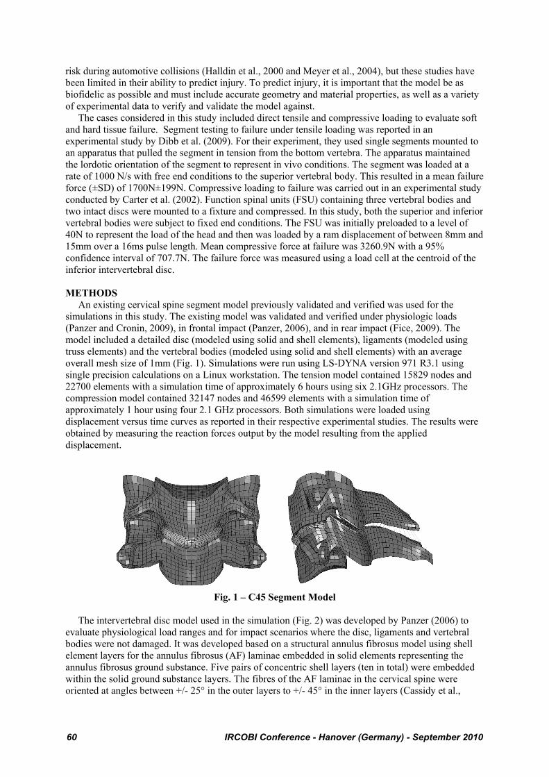
The intervertebral disc model used in the simulation (Fig. 2) was developed by Panzer (2006) to evaluate physiological load ranges and for impact scenarios where the disc, ligaments and vertebral bodies were not damaged. It was developed based on a structural annulus fibrosus model using shell element layers for the annulus fibrosus (AF) laminae embedded in solid elements representing the annulus fibrosus ground substance. Five pairs of concentric shell layers (ten in total) were embedded within the solid ground substance layers. The fibres of the AF laminae in the cervical spine were oriented at angles between +/- 25° in the outer layers to +/- 45° in the inner layers (Cassidy et al.,
60 IRCOBI Conference - Hanover (Germany) - September 2010
1989; White and Panjabi, 1990; Wagner and Lotz, 2004). The nucleus pulposus was represented with solid elements enclosed within the elements of the annulus fibrosus (Panzer, 2006).
Fig. 2 – Components of the Intervertebral Disc (Adapted from Panzer, 2006)
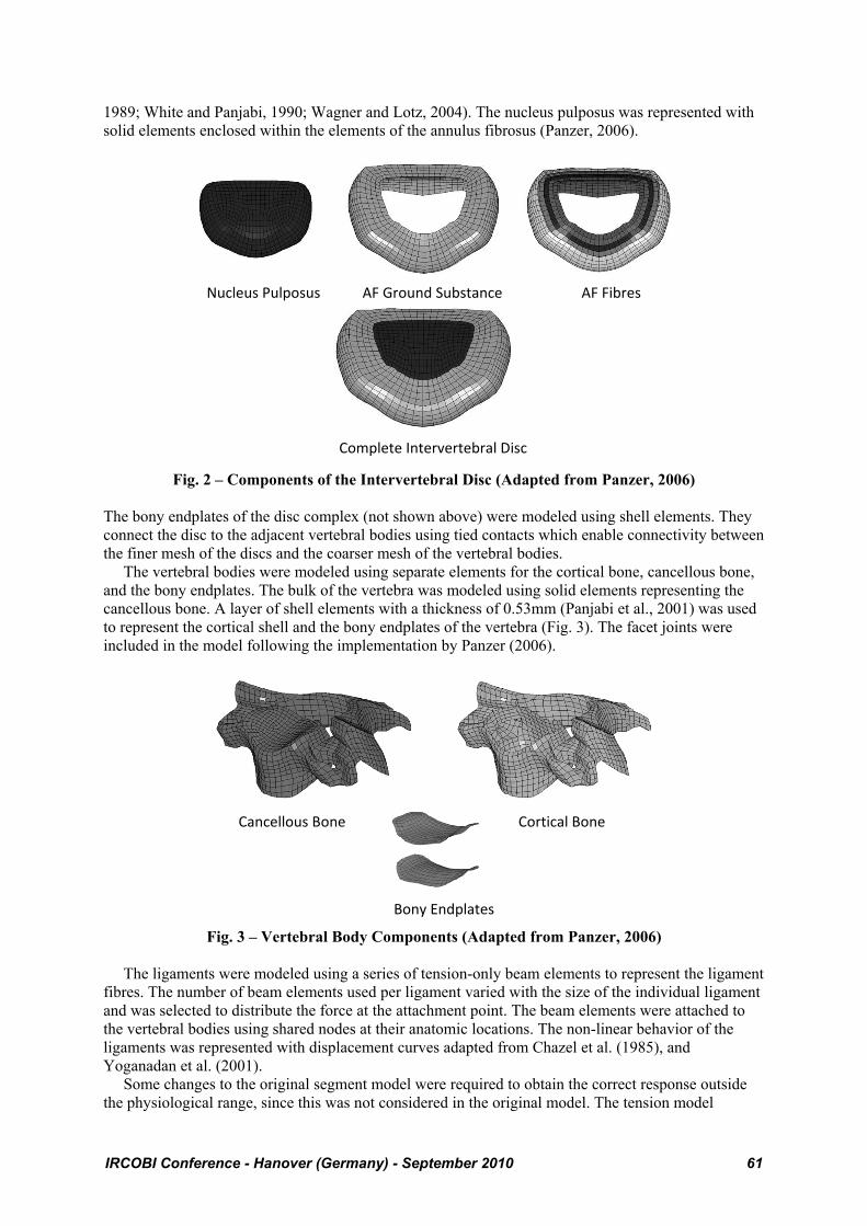
The bony endplates of the disc complex (not shown above) were modeled using shell elements. They connect the disc to the adjacent vertebral bodies using tied contacts which enable connectivity between the finer mesh of the discs and the coarser mesh of the vertebral bodies. The vertebral bodies were modeled using separate elements for the cortical bone, cancellous bone, and the bony endplates. The bulk of the vertebra was modeled using solid elements representing the cancellous bone. A layer of shell elements with a thickness of 0.53mm (Panjabi et al., 2001) was used to represent the cortical shell and the bony endplates of the vertebra (Fig. 3). The facet joints were included in the model following the implementation by Panzer (2006).
Fig. 3 – Vertebral Body Components (Adapted from Panzer, 2006)
The ligaments were modeled using a series of tension-only beam elements to represent the ligament fibres. The number of beam elements used per ligament varied with the size of the individual ligament and was selected to distribute the force at the attachment point. The beam elements were attached to the vertebral bodies using shared nodes at their anatomic locations. The non-linear behavior of the ligaments was represented with displacement curves adapted from Chazel et al. (1985), and Yoganadan et al. (2001). Some changes to the original segment model were required to obtain the correct response outside the physiological range, since this was not considered in the original model. The tension model
Nucleus Pulposus
Complete Intervertebral Disc
AF Fibres AF Ground Substance
Cancellous Bone
Bony Endplates
Cortical Bone
IRCOBI Conference - Hanover (Germany) - September 2010 61
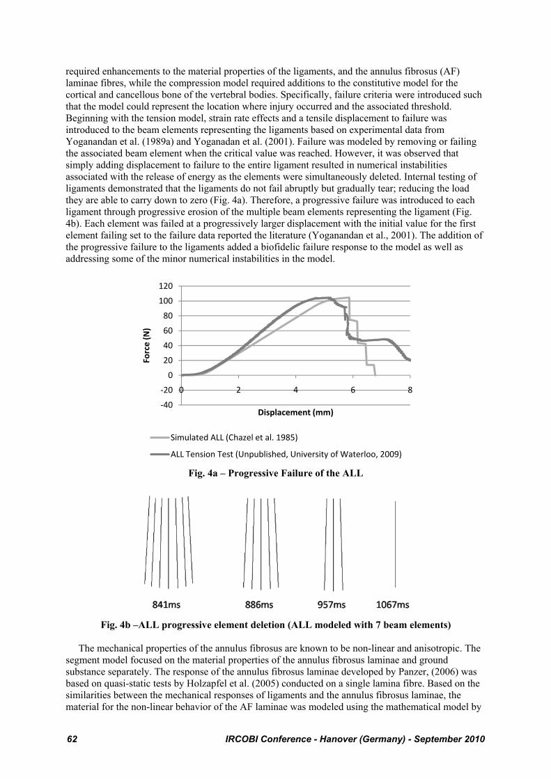
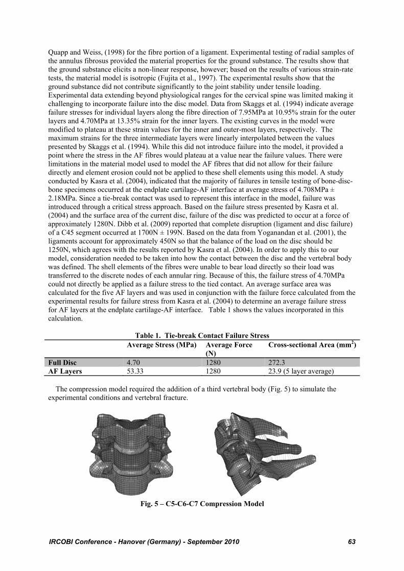
required enhancements to the material properties of the ligaments, and the annulus fibrosus (AF) laminae fibres, while the compression model required additions to the constitutive model for the cortical and cancellous bone of the vertebral bodies. Specifically, failure criteria were introduced such that the model could represent the location where injury occurred and the associated threshold. Beginning with the tension model, strain rate effects and a tensile displacement to failure was introduced to the beam elements representing the ligaments based on experimental data from Yoganandan et al. (1989a) and Yoganadan et al. (2001). Failure was modeled by removing or failing the associated beam element when the critical value was reached. However, it was observed that simply adding displacement to failure to the entire ligament resulted in numerical instabilities associated with the release of energy as the elements were simultaneously deleted. Internal testing of ligaments demonstrated that the ligaments do not fail abruptly but gradually tear; reducing the load they are able to carry down to zero (Fig. 4a). Therefore, a progressive failure was introduced to each ligament through progressive erosion of the multiple beam elements representing the ligament (Fig. 4b). Each element was failed at a progressively larger displacement with the initial value for the first element failing set to the failure data reported the literature (Yoganandan et al., 2001). The addition of the progressive failure to the ligaments added a biofidelic failure response to the model as well as addressing some of the minor numerical instabilities in the model.
Fig. 4a – Progressive Failure of the ALL
Fig. 4b –ALL progressive element deletion (ALL modeled with 7 beam elements)
The mechanical properties of the annulus fibrosus are known to be non-linear and anisotropic. The segment model focused on the material properties of the annulus fibrosus laminae and ground substance separately. The response of the annulus fibrosus laminae developed by Panzer, (2006) was based on quasi-static tests by Holzapfel et al. (2005) conducted on a single lamina fibre. Based on the similarities between the mechanical responses of ligaments and the annulus fibrosus laminae, the material for the non-linear behavior of the AF laminae was modeled using the mathematical model by
‐40
‐20
0
20
40
60
80
100
120
0 2 4 6 8
Force (N)
Displacement (mm)
Simulated ALL (Chazel et al. 1985)
ALL Tension Test (Unpublished, University of Waterloo, 2009)
62 IRCOBI Conference - Hanover (Germany) - September 2010
Quapp and Weiss, (1998) for the fibre portion of a ligament. Experimental testing of radial samples of the annulus fibrosus provided the material properties for the ground substance. The results show that the ground substance elicits a non-linear response, however; based on the results of various strain-rate tests, the material model is isotropic (Fujita et al., 1997). The experimental results show that the ground substance did not contribute significantly to the joint stability under tensile loading. Experimental data extending beyond physiological ranges for the cervical spine was limited making it challenging to incorporate failure into the disc model. Data from Skaggs et al. (1994) indicate average failure stresses for individual layers along the fibre direction of 7.95MPa at 10.95% strain for the outer layers and 4.70MPa at 13.35% strain for the inner layers. The existing curves in the model were modified to plateau at these strain values for the inner and outer-most layers, respectively. The maximum strains for the three intermediate layers were linearly interpolated between the values presented by Skaggs et al. (1994). While this did not introduce failure into the model, it provided a point where the stress in the AF fibres would plateau at a value near the failure values. There were limitations in the material model used to model the AF fibres that did not allow for their failure directly and element erosion could not be applied to these shell elements using this model. A study conducted by Kasra et al. (2004), indicated that the majority of failures in tensile testing of bone-disc-bone specimens occurred at the endplate cartilage-AF interface at average stress of 4.708MPa ± 2.18MPa. Since a tie-break contact was used to represent this interface in the model, failure was introduced through a critical stress approach. Based on the failure stress presented by Kasra et al. (2004) and the surface area of the current disc, failure of the disc was predicted to occur at a force of approximately 1280N. Dibb et al. (2009) reported that complete disruption (ligament and disc failure) of a C45 segment occurred at 1700N ± 199N. Based on the data from Yoganandan et al. (2001), the ligaments account for approximately 450N so that the balance of the load on the disc should be 1250N, which agrees with the results reported by Kasra et al. (2004). In order to apply this to our model, consideration needed to be taken into how the contact between the disc and the vertebral body was defined. The shell elements of the fibres were unable to bear load directly so their load was transferred to the discrete nodes of each annular ring. Because of this, the failure stress of 4.70MPa could not directly be applied as a failure stress to the tied contact. An average surface area was calculated for the five AF layers and was used in conjunction with the failure force calculated from the experimental results for failure stress from Kasra et al. (2004) to determine an average failure stress for AF layers at the endplate cartilage-AF interface. Table 1 shows the values incorporated in this calculation.
Table 1. Tie-break Contact Failure Stress Average Stress (MPa) Average Force
(N) Cross-sectional Area (mm2)
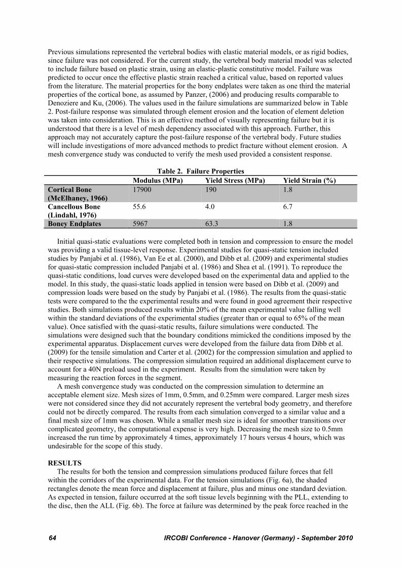
Full Disc 4.70 1280 272.3 AF Layers 53.33 1280 23.9 (5 layer average) The compression model required the addition of a third vertebral body (Fig. 5) to simulate the experimental conditions and vertebral fracture.
Fig. 5 – C5-C6-C7 Compression Model
IRCOBI Conference - Hanover (Germany) - September 2010 63
Previous simulations represented the vertebral bodies with elastic material models, or as rigid bodies, since failure was not considered. For the current study, the vertebral body material model was selected to include failure based on plastic strain, using an elastic-plastic constitutive model. Failure was predicted to occur once the effective plastic strain reached a critical value, based on reported values from the literature. The material properties for the bony endplates were taken as one third the material properties of the cortical bone, as assumed by Panzer, (2006) and producing results comparable to Denoziere and Ku, (2006). The values used in the failure simulations are summarized below in Table 2. Post-failure response was simulated through element erosion and the location of element deletion was taken into consideration. This is an effective method of visually representing failure but it is understood that there is a level of mesh dependency associated with this approach. Further, this approach may not accurately capture the post-failure response of the vertebral body. Future studies will include investigations of more advanced methods to predict fracture without element erosion. A mesh convergence study was conducted to verify the mesh used provided a consistent response.
Table 2. Failure Properties Modulus (MPa) Yield Stress (MPa) Yield Strain (%) Cortical Bone (McElhaney, 1966)
17900 190 1.8
Cancellous Bone (Lindahl, 1976)
55.6 4.0 6.7
Boney Endplates 5967 63.3 1.8 Initial quasi-static evaluations were completed both in tension and compression to ensure the model was providing a valid tissue-level response. Experimental studies for quasi-static tension included studies by Panjabi et al. (1986), Van Ee et al. (2000), and Dibb et al. (2009) and experimental studies for quasi-static compression included Panjabi et al. (1986) and Shea et al. (1991). To reproduce the quasi-static conditions, load curves were developed based on the experimental data and applied to the model. In this study, the quasi-static loads applied in tension were based on Dibb et al. (2009) and compression loads were based on the study by Panjabi et al. (1986). The results from the quasi-static tests were compared to the the experimental results and were found in good agreement their respective studies. Both simulations produced results within 20% of the mean experimental value falling well within the standard deviations of the experimental studies (greater than or equal to 65% of the mean value). Once satisfied with the quasi-static results, failure simulations were conducted. The simulations were designed such that the boundary conditions mimicked the conditions imposed by the experimental apparatus. Displacement curves were developed from the failure data from Dibb et al. (2009) for the tensile simulation and Carter et al. (2002) for the compression simulation and applied to their respective simulations. The compression simulation required an additional displacement curve to account for a 40N preload used in the experiment. Results from the simulation were taken by measuring the reaction forces in the segment. A mesh convergence study was conducted on the compression simulation to determine an acceptable element size. Mesh sizes of 1mm, 0.5mm, and 0.25mm were compared. Larger mesh sizes were not considered since they did not accurately represent the vertebral body geometry, and therefore could not be directly compared. The results from each simulation converged to a similar value and a final mesh size of 1mm was chosen. While a smaller mesh size is ideal for smoother transitions over complicated geometry, the computational expense is very high. Decreasing the mesh size to 0.5mm increased the run time by approximately 4 times, approximately 17 hours versus 4 hours, which was undesirable for the scope of this study. RESULTS The results for both the tension and compression simulations produced failure forces that fell within the corridors of the experimental data. For the tension simulations (Fig. 6a), the shaded rectangles denote the mean force and displacement at failure, plus and minus one standard deviation. As expected in tension, failure occurred at the soft tissue levels beginning with the PLL, extending to the disc, then the ALL (Fig. 6b). The force at failure was determined by the peak force reached in the
64 IRCOBI Conference - Hanover (Germany) - September 2010
simulation before a significant drop off occurred. Two values were reported for failure displacement based on major failure and ultimate failure.
Fig. 6a – Simulation Response in Tension
Fig. 6b – Failure Sequence in Tension
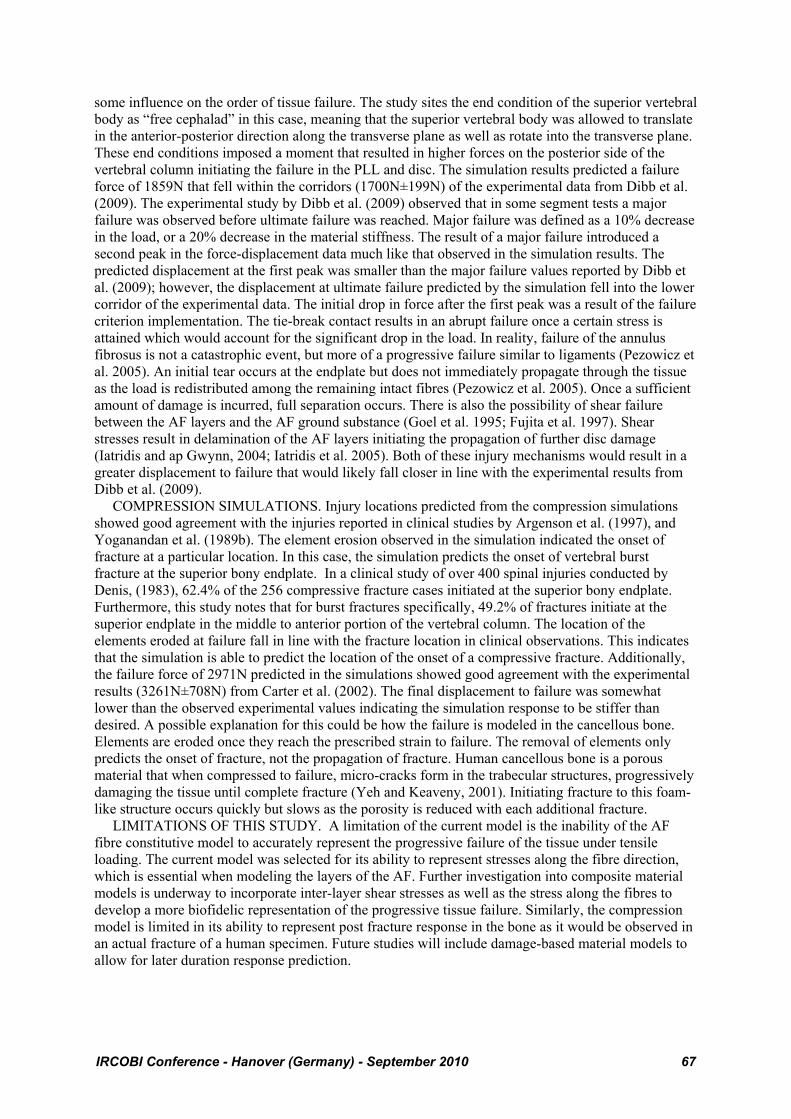
In compression, the failure observed occurred in the cortical and cancellous bone of the middle vertebral body. The simulation showed the failure location to be primarily at the superior bony endplate (Fig. 7a) from the midline to the anterior portion of the column. Similar to the tension case, the peak failure force was determined by a significant drop in the load (Fig. 7b).
0.0
0.5
1.0
1.5
2.0
2.5
3.0
3.5
0.0 2.0 4.0 6.0 8.0 10.0 12.0
Force (kN)
Displacement (mm)
Predicted Response Dibb et al (2009)
1 – Time Zero 2 – PLL Failure
3 – Disc Failure 4 – ALL Failure
IRCOBI Conference - Hanover (Germany) - September 2010 65
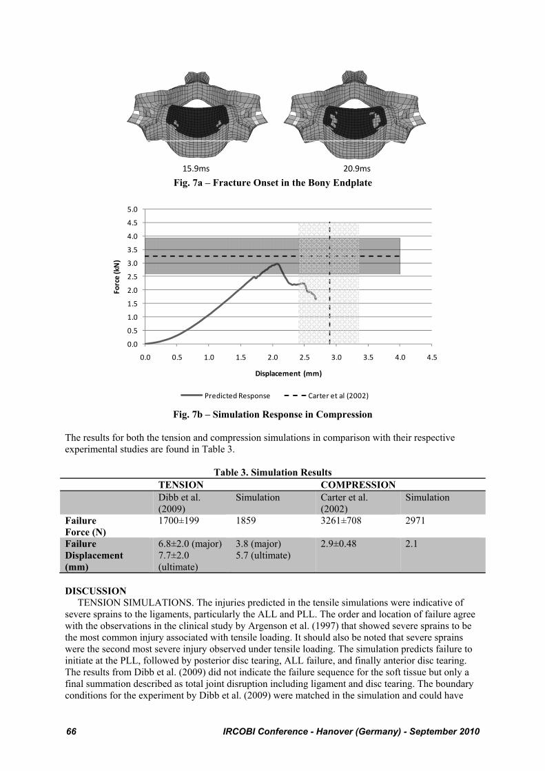
Fig. 7a – Fracture Onset in the Bony Endplate
Fig. 7b – Simulation Response in Compression
The results for both the tension and compression simulations in comparison with their respective experimental studies are found in Table 3.
Table 3. Simulation Results TENSION COMPRESSION Dibb et al.
(2009) Simulation Carter et al.
(2002) Simulation
Failure Force (N)
1700±199 1859 3261±708 2971
Failure Displacement (mm)
6.8±2.0 (major) 7.7±2.0 (ultimate)
3.8 (major) 5.7 (ultimate)
2.9±0.48 2.1
DISCUSSION TENSION SIMULATIONS. The injuries predicted in the tensile simulations were indicative of severe sprains to the ligaments, particularly the ALL and PLL. The order and location of failure agree with the observations in the clinical study by Argenson et al. (1997) that showed severe sprains to be the most common injury associated with tensile loading. It should also be noted that severe sprains were the second most severe injury observed under tensile loading. The simulation predicts failure to initiate at the PLL, followed by posterior disc tearing, ALL failure, and finally anterior disc tearing. The results from Dibb et al. (2009) did not indicate the failure sequence for the soft tissue but only a final summation described as total joint disruption including ligament and disc tearing. The boundary conditions for the experiment by Dibb et al. (2009) were matched in the simulation and could have
15.9ms 20.9ms
0.0
0.5
1.0
1.5
2.0
2.5
3.0
3.5
4.0
4.5
5.0
0.0 0.5 1.0 1.5 2.0 2.5 3.0 3.5 4.0 4.5
Force (kN)
Displacement (mm)
Predicted Response Carter et al (2002)
66 IRCOBI Conference - Hanover (Germany) - September 2010
some influence on the order of tissue failure. The study sites the end condition of the superior vertebral body as “free cephalad” in this case, meaning that the superior vertebral body was allowed to translate in the anterior-posterior direction along the transverse plane as well as rotate into the transverse plane. These end conditions imposed a moment that resulted in higher forces on the posterior side of the vertebral column initiating the failure in the PLL and disc. The simulation results predicted a failure force of 1859N that fell within the corridors (1700N±199N) of the experimental data from Dibb et al. (2009). The experimental study by Dibb et al. (2009) observed that in some segment tests a major failure was observed before ultimate failure was reached. Major failure was defined as a 10% decrease in the load, or a 20% decrease in the material stiffness. The result of a major failure introduced a second peak in the force-displacement data much like that observed in the simulation results. The predicted displacement at the first peak was smaller than the major failure values reported by Dibb et al. (2009); however, the displacement at ultimate failure predicted by the simulation fell into the lower corridor of the experimental data. The initial drop in force after the first peak was a result of the failure criterion implementation. The tie-break contact results in an abrupt failure once a certain stress is attained which would account for the significant drop in the load. In reality, failure of the annulus fibrosus is not a catastrophic event, but more of a progressive failure similar to ligaments (Pezowicz et al. 2005). An initial tear occurs at the endplate but does not immediately propagate through the tissue as the load is redistributed among the remaining intact fibres (Pezowicz et al. 2005). Once a sufficient amount of damage is incurred, full separation occurs. There is also the possibility of shear failure between the AF layers and the AF ground substance (Goel et al. 1995; Fujita et al. 1997). Shear stresses result in delamination of the AF layers initiating the propagation of further disc damage (Iatridis and ap Gwynn, 2004; Iatridis et al. 2005). Both of these injury mechanisms would result in a greater displacement to failure that would likely fall closer in line with the experimental results from Dibb et al. (2009). COMPRESSION SIMULATIONS. Injury locations predicted from the compression simulations showed good agreement with the injuries reported in clinical studies by Argenson et al. (1997), and Yoganandan et al. (1989b). The element erosion observed in the simulation indicated the onset of fracture at a particular location. In this case, the simulation predicts the onset of vertebral burst fracture at the superior bony endplate. In a clinical study of over 400 spinal injuries conducted by Denis, (1983), 62.4% of the 256 compressive fracture cases initiated at the superior bony endplate. Furthermore, this study notes that for burst fractures specifically, 49.2% of fractures initiate at the superior endplate in the middle to anterior portion of the vertebral column. The location of the elements eroded at failure fall in line with the fracture location in clinical observations. This indicates that the simulation is able to predict the location of the onset of a compressive fracture. Additionally, the failure force of 2971N predicted in the simulations showed good agreement with the experimental results (3261N±708N) from Carter et al. (2002). The final displacement to failure was somewhat lower than the observed experimental values indicating the simulation response to be stiffer than desired. A possible explanation for this could be how the failure is modeled in the cancellous bone. Elements are eroded once they reach the prescribed strain to failure. The removal of elements only predicts the onset of fracture, not the propagation of fracture. Human cancellous bone is a porous material that when compressed to failure, micro-cracks form in the trabecular structures, progressively damaging the tissue until complete fracture (Yeh and Keaveny, 2001). Initiating fracture to this foam-like structure occurs quickly but slows as the porosity is reduced with each additional fracture. LIMITATIONS OF THIS STUDY. A limitation of the current model is the inability of the AF fibre constitutive model to accurately represent the progressive failure of the tissue under tensile loading. The current model was selected for its ability to represent stresses along the fibre direction, which is essential when modeling the layers of the AF. Further investigation into composite material models is underway to incorporate inter-layer shear stresses as well as the stress along the fibres to develop a more biofidelic representation of the progressive tissue failure. Similarly, the compression model is limited in its ability to represent post fracture response in the bone as it would be observed in an actual fracture of a human specimen. Future studies will include damage-based material models to allow for later duration response prediction.
IRCOBI Conference - Hanover (Germany) - September 2010 67

CONCLUSIONS Simulations of loading conditions causing failure in tension and compression modes of loading have provided a solid basis for future studies related to cervical spine injury simulation. The simulations were developed using detailed geometric data and available material test data in the literature. Importantly, the material properties and failure criteria implemented were all based on existing data and were not calibrated to the validation cases used in the study. Progressive failure of ligaments, modeled using multiple beam elements, provided a representative, computationally efficient and numerically stable method of predicting response and failure. The advancements using progressive failure in the ligaments to produce a more biofidelic failure response, as well as predicting injury location, represent an area not previously investigated in great detail. Tension failure of the disc was modeled through contact failure at the ends of the lamina, and provided good prediction of the overall failure force. Future studies will include implementation of an improved constitutive model to allow for failure within the AF lamina. Compressive failure was predicted to initiate in the vertebral body endplates, in agreement with the literature, and the predicted loads were in good agreement with the experimental validation cases. The ability to predict injury in automotive collision scenarios at the tissue level represents a new development in this area. Validating injurious loading conditions at the segment level will lead to improved simulations for predicting injury in full cervical spine models to evaluate injurious loading scenarios and potential mitigation strategies. Further investigation into constitutive models and post-failure response modeling will continue to advance injury simulation. ACKNOWLEDEMENTS The authors gratefully acknowledge support from the Global Human Body Models Consortium, and the advice of Mr. Matthew Panzer. REFERENCES Argenson, C., de Peretti, F., Ghabris, A., Eude, P., Lovet, J., and Hovorka, I., 2002. Classification of
Lower Cervical Spine Injuries. European Journal of Orthopaedic Surgery and Traumatology 7(4), 215 – 229.
Blacksin, M. F., 1993. Patterns of Fracture After Air Bag Deployment, Journal of Trauma 35(6), 840–843.
Burney, R.E., Maio, R.F., Maynard, F., and Karunas, R. 1993. Incidence, Characteristics, and Outcome of Spinal Cord Injury at Trauma Centers in North America. Archives of Surgery 128(5), 596 – 599.
Carter, J.W., Ku, G.S., Nuckley, D.J., and Ching, R.P., 2002. Tolerance of the Cervical Spine to Eccentric Axial Compression. Stapp Car Crash Journal 46, 441 – 459.
Cassidy, J.J., Hiltner, A., and Baer, E., 1989. Hierarchical Structure of the Intervertebral Disc. ConnectiveTissue Research 23(1), 75 – 88.
Chazel, J., Tanguy, A., Bourges, M., Gaurel, G., Escande, G., Guillot, M., and Vanneuville, G., 1985. Biomechanical Properties of Spinal Ligaments and a Histological Study of the Supraspinal Ligament in Traction. Journal of Biomechanics 18(3), 167 – 176.
Cusick, J.F., and Yoganandan, N., 2002. Biomechanics of the Cervical Spine 4: Major Injuries. Clinical Biomechanics 17, 1 – 20.
Daffner, R.H., Sciulli, R.L., Rodriguez, A., and Protech, J., 2006. Imaging for Evaluation of Suspected Cervical Spine Trauma: A 2-Year Analysis. Injury, International Journal of the Care of the Injured 37(7), 652-658.
Denis, F., 1983. The Three Column Spine and Its Significance in the Classification of Acute Thorocolumbar Spinal Injuries. Spine 8(8). 817 – 831.
Denoziere, G., and Ku, D.N., 2006. Biomechanical Comparison Between Fusion of Two Vertebrae and Implantation of an Artificial Intervertebral Disc. Journal of Biomechanics 39(4), 766 – 775.
Dibb, A.T., Nightingale, R.W., Luck, J.F., Chancey, V.C., Fronheiser, L.E., and Myers, B.S., 2009. Tension and Combined Tension-Extension Structural Response and Tolerance Properties of the Human Male Ligamentous Cervical Spine. Journal of Biomechanical Engineering 131, 1 – 10.
68 IRCOBI Conference - Hanover (Germany) - September 2010
Fujita, Y., Duncan, N.A., and Lotz, J.C., 1997. Radial Tensile Properties of the Lumbar Annulus Fibrosus are Site and Degeneration Dependent. Journal of Orthopaedic Research 15, 814 – 819.
Fice, J., Cronin, D.S., and Panzer, M.B., 2009. Investigation of facet joint response under rear impact conditions using FE model of the cervical spine. ESV. Stuttgart, #09-0154.
Goel, V.K., Monroe, B.T., Gilbertson, L.G., and Brinkmann, P., 1995. Interlaminar Shear Stresses and Laminae Separation in a Disc. Spine 20(6), 689 – 698.
Halldin, P.H., Brolin, K., Kleiven, S., von Holst, H., Jakobsson, L., and Palmertz, C., 2000. Investigation ofConditions that Affect Neck Compression-Flexion Injuries Using Numerical Techniques. Proceedings from the 44th Stapp Car Crash Conference. SAE 2000-01-SC10.
Holzapfel, G.A., Schulze-Bauer, C.A.J., Feigl, G., and Regitnig, P., 2005. Single Lamellar Mechanics of the Human Lumbar Annulus Fibrosus. Biomechanics and Modeling in Mechanobiology 3, 125 – 140.
Iatridis, J.C., and ap Gwynn, I., 2004. Mechanisms for Mechanical Damage in the Intervertebral Disc Annulus Fibrosus. Journal of Biomechanics 31, 535 – 544.
Iatridis, J.C., MacLean, J.J., and Ryan, D.A., 2005. Mechanical Damage to the Intervertebral Disc Annulus Fibrosus Subjected to Tensile Loading. Journal of Biomechanics 38, 557 – 565.
Kasra, M., Parnianpour, M., Shirazi-Adl, A., Wang, J.L., and Grynpas, M.D., 2004. Effect of Strain Rate on Tensile Properties of Sheep Disc Annulus Fibrosus. Technology and Health Care 12, 333 – 342.
Kleinberger, M., and Summers, L., 1997. Mechanism of Injuries for Adults and Children Resulting From Airbag Interaction, 41st Annual Meeting of the Association for the Advancement of Automotive Medicine 405–420.
Kumaresan, S., Yoganandan, N., Pintar, F.A., Voo, L.M., Cusick, J.F., and Larson, S.J., 1997. Finite Element Modeling of Cervical Laminectomy with Graded Facetectomy. Journal of Spinal Disorders 10(1), 40 – 46.
Lindahl, O., 1976. Mechanical Properties of Dried Defatted Spongy Bone. Acta Orthopaedica Scandinavica 47,11 – 19.
McElhaney, J.H., 1966. Dynamic Response of Bone and Muscle Tissue. Journal of Applied Physiology 21, 1231 – 1236.
Meyer, F., Bourdet, N., Deck, C., Willinger, R., and Raul, J.S., 2004. Human Neck Finite Element Model Development and Validation Against Original Experimental Data. Proceedings from the 48th Stapp Car Crash Conference, 177 – 206. SAE 2004-22-0008.
Myers, B.S., and Winkelstein, B.A., 1995. Epidiemiology, Classification, Mechanism, and Tolerance of Human Cervical Spine Injuries. Critical Reviews in Biomedical Engineering 23(5&6), 307 – 409.
Ng, H.W., Teo, E.C., and Lee, V.S., 2004. Statistical Factorial Analysis on the Material Property Sensitivity of the Mechanical Response of the C4-C6 Under Compression, Anterior and Posterior Shear. Journal of Biomechanics 37, 771 – 777.
Panjabi, M.M., Summers, D.J., Pelker, R.R., Videman, T., Friedlaender, G.E., and Southwick, W.O., 1986. Three-Dimensional Load-Displacement Curves Due to Forces on the Cervical Spine. Journal of Orthopaedic Research 4, 152 – 161.
Panjabi, M.M., Chen, N.C., Shin, E.K., and Wang, J-L., 2001. The Cortical Shell Architecture of Human Cervical Vertebral Bodies. Spine 26(22), 2478 – 2484.
Panzer, M.B., 2006. Numerical Modelling of the Human Cervical Spine in Frontal Impact. MASc Thesis, University of Waterloo.
Panzer, M.B., and Cronin, D.S., 2009. C4-C5 Segment Finite Element Model Development, Validation, and Load Sharing Investigation. Journal of Biomechanics 42, 480 – 490.
Pezowicz, C.A., Roberston, P.A., and Broom, N.D., 2005. Intralamellar Relationships within the Collagenous Architecture of the Annulus Fibrosus Imaged in its Fully Hydrated State. Journal of Anatomy 207, 299 – 312.
Quapp, K.M., and Weiss, J.A., 1998. Material Characterization of Human Medial Collateral Ligament. Journal of Biomechanical Engineering 120, 757 – 763.
Riggins, R.S, and Kraus, J.F., 1977. The Risk of Neurologic Damage with Fractures to the Vertebrae. Journal of Trauma 17(2), 126 – 133.
IRCOBI Conference - Hanover (Germany) - September 2010 69

Robertson, A., Branfoot, T., Barlow, I.F., and Giannoudies, P.V., 2002. Spinal Injury Patterns Resulting From Car and Motorcycle Accidents. Spine 27(24), 2825 – 2830.
Sato, Y., Ohshima, T., and Kondo, T., 2002. Air Bag Injuries – A Literature Review in Consideration of Demands in Forensic Autopsies, Forensic Science International 128(3), 162–167.
Skaggs, D.L., Weidenbaum, M., Iatridis, J.C., Ratcliffe, A., and Mow, V.C., 1994. Regional Variation in Tensile Properties and Biochemical Composition of the Human Lumbar Annulus Fibrosus. Spine 19(12), 1310 – 1319.
Shea, M., Edwards, W.T., White, A.A., and Hayes, W.C., 1991. Variations of Stiffness and Strength along the Human Cervical Spine. Journal of Biomechanics 24(2), 95 – 107.
Traynelis, V. C., and Gold, M., 1993. Cervical Spine Injury in an Air-Bag-Equipped Vehicle, Journal of Spinal Disorders 6(1) 60–61.
Teo, E.C., and Ng, H.W., 2001. Evaluation of the Role of Ligaments, Facets and Disc Nucleus in Lower Cervical Spine Under Compression and Sagittal Moments Using Finite Element Method. Medical Engineering and Physics 23, 155 – 164.
Van Ee, C.A., Nightingale, R.W., Camacho, D.L.A., Chancey, V.C., Knaub, K.E., Sun, E.A., and Myers, B.S., 2000. Tensile Properties of the Human Muscular and Ligamentous Cervical Spine. Proceedings from the 44th Stapp Car Crash Conference. SAE 2000-01-SC07.
Wagner, D.R., and Lotz, J.C., 2004. Theoretical Model and Experimental Results for the Nonlinear Elastic Behavior of Human Annulus Fibrosus. Journal of Orthopaedic Research 22, 901 – 909.
White, A.A., and Panjabi, M.M., 1990. Clinical Biomechanics of the Spine. 2nd Ed. J.B. Lippincott Co., Philadelphia.
Yeh, O.C., and Keaveny, T.M., 2001. Relative Roles of Microdamage and Microfracture in the Mechanical Behavior of Trabecular Bone. Journal of Orthopaedic Research 19, 1001 – 1007.
Yoganandan, N., Pintar, F., Butler, J., Reinartz, J., Sances, A., and Larson, S.J., 1989a. Dynamic Response of Human Cervical Spine Ligaments. Spine 14(10), 1102 – 1110.
Yoganandan, N., Pintar, F., Haffner, M., Jentzen, J., Mainma, D.J., Weinshel, S.S., Larson, S.J., Nichols, H., and Sances, A., 1989b. Epidemiology and Injury Biomechanics of Motor Vehicle Related Trauma to the Human Spine. Proceedings from the 33rd Stapp Car Crash Conference, 223 – 242. SAE 892438.
Yoganandan, N., Kumaresan, S., and Pintar, FA., 2001. Biomechanics of the Cervical Spine Part 2: Cervical Spine Soft Tissue Responses and Biomechanical Modeling, Clinical Biomechanics 16, 1 – 27.
70 IRCOBI Conference - Hanover (Germany) - September 2010