Embed Size (px)
Citation preview
E No: E0315 Rev. 01 File Ref: 800-64
CP No.: CP0316 Rev. 01 Page: 1 of 22
CERTIFIEDTEST REPORT
COOPER POWER SYSTEMSFOUR POSITION SECTIONALIZING
LOADBREAK SWITCH12.5 kA Momentary and Making Rating
REV. 01 DATE: December 3, 2004 • ORIGINAL REPORT DATE: January 13, 2004 • © Cooper Power Systems, Inc.


E No: E0315 Rev. 01 File Ref: 800-64
CP No.: CP0316 Rev. 01 Page: 3 of 22
Table of Contents
1. Introduction ................................................................................................................................................................ 4
1.1. Applicable Industry Standards ...................................................................................................................... 4
1.2. Additional Mechanical Tests ......................................................................................................................... 4
1.3. Independent Laboratories............................................................................................................................. 5
2. Scope ......................................................................................................................................................................... 6
3. Certification Statement............................................................................................................................................... 7
4. Certification Summary................................................................................................................................................ 7
4.1. Interrupting Current Tests ............................................................................................................................. 7
4.1.1. Load Current Tests....................................................................................................................... 7
4.1.2. Magnetizing Current Tests ........................................................................................................... 9
4.1.3. Cable Charging Current Tests.................................................................................................... 11
4.2. Momentary Current Tests ........................................................................................................................... 12
4.3. Making Current Tests.................................................................................................................................. 13
4.4. AC Withstand Tests .................................................................................................................................... 14
4.5. Thermal Tests ............................................................................................................................................. 15
4.6. Mechanical Operations Tests ..................................................................................................................... 16
4.7. Impulse Withstand Tests............................................................................................................................. 17
4.8. DC Withstand Tests .................................................................................................................................... 18
4.9. One-second Current Test ........................................................................................................................... 18
4.10. Pressure Test.............................................................................................................................................. 19
4.11. Vibration Test .............................................................................................................................................. 19
4.12. Packaging Test ........................................................................................................................................... 20
4.13. Operating Force Test .................................................................................................................................. 21
4.14. Operating Travel Test ................................................................................................................................. 21

E No: E0315 Rev. 01 File Ref: 800-64
CP No.: CP0316 Rev. 01 Page: 4 of 22
1. Introduction
Continuous improvement is an ongoing objective and activity of Cooper Power Systems. Design improvementsare initiated to integrate new design concepts and/or new technology, support continuous improvement, help maintainproduct competitiveness and provide features requested by customers. Recent changes to industry standards haveaffected the testing requirements for load break devices mounted in fluid filled tanks. Additionally, a new dielectric fluidhas been introduced and verification of switch performance in this fluid is also required.
1.1. Applicable Industry Standards
The four position sectionalizing switch discussed herein has been designed for applications in padmountedtransformers and switchgear. No single industry standard has been published that includes the performance criteriaand test regimen for both these applications. Consequently, the requirements must be drawn from industry standardsapplicable to both transformers and switchgear. These include:
• IEEE Std C37.71-2001 IEEE Standard for Three-Phase, Manually Operated Subsurface and Vault Load-Interrupting Switches for Alternating-Current Systems
• IEEE Std C57.12.00-2000 IEEE Standard General Requirements for Liquid-Immersed Distribution, Power, andRegulating Transformers
The Switchgear Committee of the IEEE Power Engineering Society has worked to better define the testrequirements and methods for products under its charge. Most significant has been the inclusion of specific inherenttransient recovery voltage (TRV) levels to the load switching tests. The power system response to current interruptiongenerates TRV. Circuits with high TRV are more difficult to interrupt. The design of the product covered in thiscertified test report has been fully tested to the new TRV requirements.
Additionally, the product covered in this certified test report has been fully tested in three different dielectric fluids;transformer oil, R-Temp, and Envirotemp FR3. The dielectric fluid surrounding the switch serves to insulate thecurrent carrying parts from each other and ground. It also plays a critical role in controlling and extinguishing the arcsgenerated during switching tests. Different fluids will vary in their reaction to arcs and this necessitates testing toinsure the design compensates for these differences.
1.2. Additional Mechanical Tests
The regimen for design verification testing consists of tests defined by industry standards and tests defined by themanufacturer, but influenced by the safety and product reliability needs of the user. Over time, the users haveexpressed interest in certain tests falling within the later category of testing. The methods and procedures for thesetests are not defined by industry standards, but have been developed through years of design experience andsummarized in this report. These tests are included in this report and include:
• Vibration Test
• Packaging Test
• Operating Force Test
• Operating Travel Test

E No: E0315 Rev. 01 File Ref: 800-64
CP No.: CP0316 Rev. 01 Page: 5 of 22
1.3. Independent Laboratories
The Industry Standard switching tests were performed by third party certified laboratories. The followingaccredited testing facilities were used for electrical testing:
Thomas A. Edison Power Test Lab Laboratorio de Pruebas de Equipos y Materiales (LAPEM)Franksville, WI Irapuato, MexicoA2LA Laboratory Certification #: 145701 NMX-EC-17025-1MNC-2000 number EE-012-093/03
The following report summarizes testing completed on production samples to verify that published electrical andmechanical ratings to prescribed industry standards were attained.

E No: E0315 Rev. 01 File Ref: 800-64
CP No.: CP0316 Rev. 01 Page: 6 of 22
2. Scope
The family of four position sectionalizing switches of Base Part Number LS4_ _12_, covered by the testingsummarized here-in can be described functionally as:
A mounting system consisting of either a self-supporting or bolt-in switch body.
An operating/actuating system common to all switch assemblies, except the stored energy increases withincreasing number of decks (phases) and increasing number of contacts engaged.
A dielectric system of insulation and switch body parts common to all switch assemblies.
A current carrying system consisting of conductors (blades, terminals, etc.) of a material and cross-sectioncommon to all switch assemblies including Break-Before-Make and Make-Before-Break “V” and “T” blade typeswitches, and a current interchange specific to “V” and “Selector Blade” switch configurations.
The switch samples tested incorporated each of the systems described above. Combinations of systems wereselected to validate the design to the most onerous application. For example, the switch configurations that includeboth types of current interchanges (“V” or Selector blade types) were selected for the continuous current thermal tests.The switch configurations that required the most (“T” blade type) and least (Selector blade type) force to actuate foreach mechanism variation were used for the mechanical life testing. The switch configurations that impressed all arcenergy across only one contact gap (“V” or Selector blade types) were used for switching tests.
Wherever possible, the preferred ratings for the switches were obtained from industry standards. The preferredratings that most closely match the applications for the switch family are defined in Table 2 of IEEE Std C37.71-2001for Class 1 “Tap Switch” (not to be confused with tap changer switches used to adjust the turns ratio of transformers).However, testing was completed at higher than established ratings in two significant categories:
Line 5 of Table 2 requires Continuous Load Interrupting Current to be 200A at 27kV. The switch familydescribed herein was tested to 300A at 27kV. This value was established by interpolation when the switchwas first introduced in the 1970’s and has been subsequently specified by many users.
E No: E0315 Rev. 01 File Ref: 800-64
CP No.: CP0316 Rev. 01 Page: 7 of 22
Line 8 of Table 2 requires a Short-time Current of 10kA symmetrical at 38kV. The switch family describedherein has been tested to 12.5kA symmetrical at 38kV.
A switch capable of withstanding 16kA symmetrical momentary and making currents has been fully tested per IEC60265-1998. See Certified Test Report CP0313 for more information on this switch.
3. Certification Statement
Design tests conducted and the data presented in this document are in accordance with all applicable sectionsIEEE Std C37.71-2001. Cooper Power Systems Four Position Sectionalizing Loadbreak switches rated 600A/15kV,300A/27kV, 200A/38kV meet or exceed all applicable requirements of the above referenced standard in accordancewith the following sections of this document.
4. Certification Summary
4.1. Interrupting Current Tests
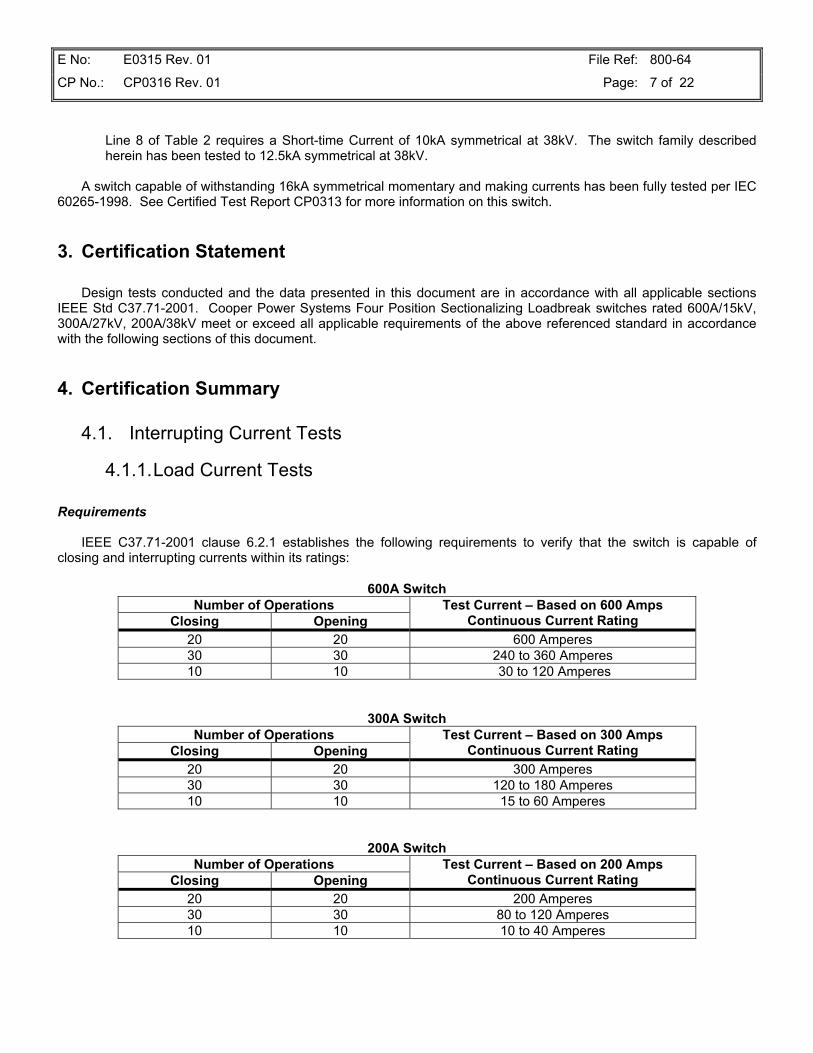
4.1.1. Load Current Tests
Requirements
IEEE C37.71-2001 clause 6.2.1 establishes the following requirements to verify that the switch is capable ofclosing and interrupting currents within its ratings:
600A SwitchNumber of Operations
Closing OpeningTest Current – Based on 600 Amps
Continuous Current Rating20 20 600 Amperes30 30 240 to 360 Amperes10 10 30 to 120 Amperes
300A SwitchNumber of Operations
Closing OpeningTest Current – Based on 300 Amps
Continuous Current Rating20 20 300 Amperes30 30 120 to 180 Amperes10 10 15 to 60 Amperes
200A SwitchNumber of Operations
Closing OpeningTest Current – Based on 200 Amps
Continuous Current Rating20 20 200 Amperes30 30 80 to 120 Amperes10 10 10 to 40 Amperes
E No: E0315 Rev. 01 File Ref: 800-64
CP No.: CP0316 Rev. 01 Page: 8 of 22
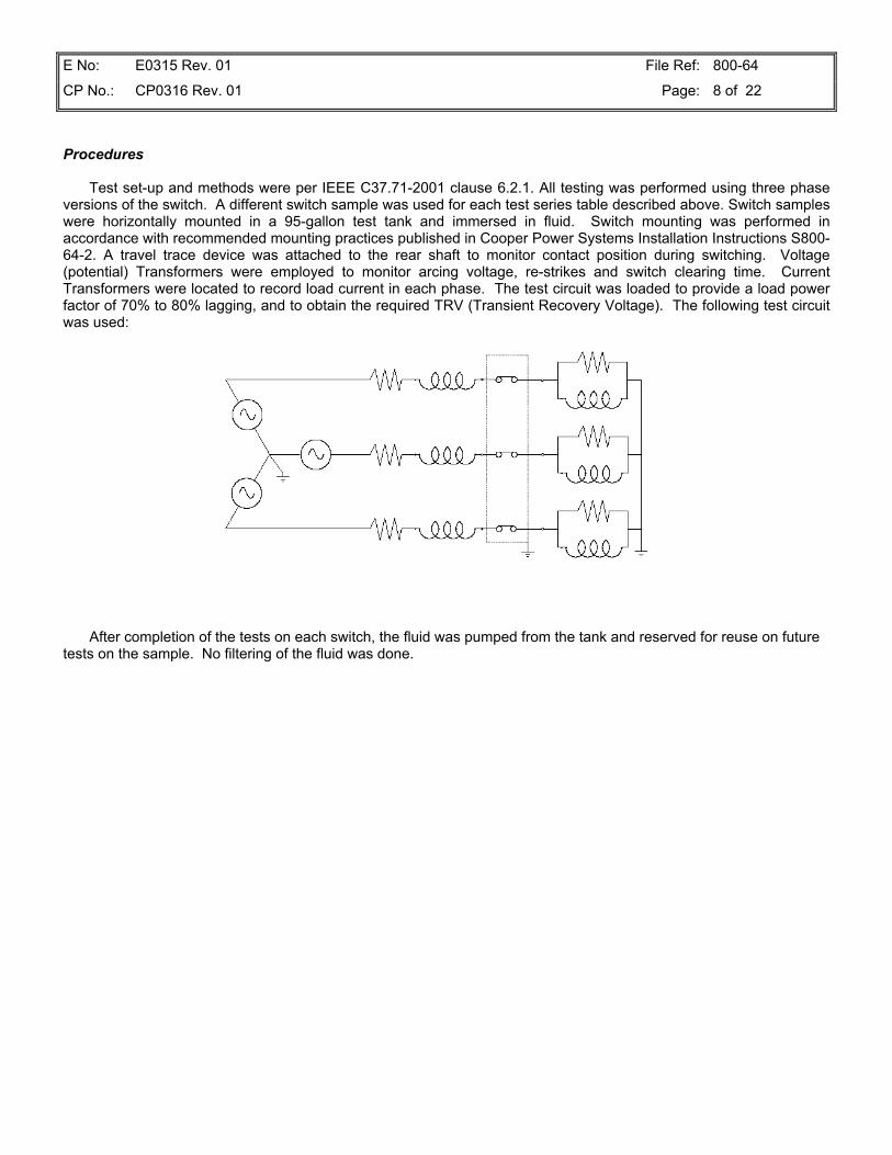
Procedures
Test set-up and methods were per IEEE C37.71-2001 clause 6.2.1. All testing was performed using three phaseversions of the switch. A different switch sample was used for each test series table described above. Switch sampleswere horizontally mounted in a 95-gallon test tank and immersed in fluid. Switch mounting was performed inaccordance with recommended mounting practices published in Cooper Power Systems Installation Instructions S800-64-2. A travel trace device was attached to the rear shaft to monitor contact position during switching. Voltage(potential) Transformers were employed to monitor arcing voltage, re-strikes and switch clearing time. CurrentTransformers were located to record load current in each phase. The test circuit was loaded to provide a load powerfactor of 70% to 80% lagging, and to obtain the required TRV (Transient Recovery Voltage). The following test circuitwas used:
After completion of the tests on each switch, the fluid was pumped from the tank and reserved for reuse on futuretests on the sample. No filtering of the fluid was done.

E No: E0315 Rev. 01 File Ref: 800-64
CP No.: CP0316 Rev. 01 Page: 9 of 22
Test Results
Number of Close/OpenOperations and Breaking
Current (avg.)Test Voltage(min – max)
TRV PeakVoltage and Time
(avg.)Fluid
15.65-15.97 kV15.63-15.74 kV
20 C/O At 638 A 30 C/O At 331 A10 C/O At 63 A 15.65-15.74 kV
4.3 kV137 µs Transformer Oil
15.75-15.89 kV15.70-15.93 kV
21 C/O At 644 A30 C/O At 334 A 10 C/O At 59 A 15.66-16.15 kV
4.19 kV141.35 µs R-Temp
15.50-15.68 kV15.73-15.89 kV
21 C/O At 639 A 30 C/O At 333 A10 C/O At 59 A 15.62-15.74 kV
4.19 kV141.35 µs EFR3
28.15-28.50 kV27.88-28.09 kV
24 C/O At 307 A 30 C/O At 157 A 10 C/O At 50 A 27.97-28.24 kV
9.95 kV288.34 µs Transformer Oil
28.15-28.50 kV27.88-28.09 kV
23 C/O At 307 A32 C/O At 157 A10 C/O At 50 A 27.97-28.24 kV
9.95 kV288.34 µs R-Temp
27.7-28.5 kV27.9-28.1 kV
22 C/O At 305 A30 C/O At 156 A 10 C/O At 50 A 27.9-28.2 kV
8.97 kV270.52 µs EFR3
38.0-38.4 kV38.1-38.6 kV
21 C/O At 204 A30 C/O At 102 A 11 C/O At 29 A 38.1-38.7 kV
15.56 kV409.62 µs Transformer Oil
38.3-39.4 kV38.4-38.7 kV
21 C/O At 207 A 30 C/O At 103 A10 C/O At 30 A 38.2-38.6 kV
16.14 kV406.34 µs R-Temp
38.1-38.7 kV38.4-38.8 kV
23 C/O At 205 A30 C/O At 103 A 10 C/O At 30 A 38.3-38.5 kV
16.14 kV406.34 µs EFR3
4.1.2. Magnetizing Current Tests
Requirements
IEEE C37.71-2001 clause 6.2.2 establishes the following requirements to verify that the switch is capable ofclosing and interrupting currents present when switching highly inductive loads such as motors or transformers.
15.5 kV Switch RatingNumber of Operations
Closing OpeningTest Current – Based on 15.5 kV
Switch Rating10 10 21 Amperes
27.0 kV Switch RatingNumber of Operations
Closing OpeningTest Current – Based on 27.0 kV(1)
Switch Rating10 10 10.5 Amperes
Note 1: For a continuous current rating of 300A, the Magnetizing current was derived by interpolation.

E No: E0315 Rev. 01 File Ref: 800-64
CP No.: CP0316 Rev. 01 Page: 10 of 22
38.0 kV Switch RatingNumber of Operations
Closing OpeningTest Current – Based on 38.0 kV
Switch Rating10 10 7 Amperes
Procedures
Test set-up and methods were per IEEE C37.71-2001 clause 6.2.2. All testing was performed using the switchsamples, test tanks, and fluid from Load Current switch testing. A travel trace device was attached to the rear shaft tomonitor contact position during switching. Voltage (potential) Transformers were employed to monitor arcing voltage,re-strikes and switch clearing time. The test circuit was loaded to provide a load power factor of 5% to 10% lagging.The following test circuit was used:
Test Results
Number of Close/OpenOperations and Breaking
Current (avg.)Test Voltage(min – max) Fluid
10 C/O at 21.2 A 15.9-16.7 kV Transformer Oil10 C/O at 21.17 A 15.76-15.95 kV R-Temp10 C/O at 21.16 A 15.77-15.87 kV EFR312 C/O at 11.5 A 27.85-27.97 kV Transformer Oil13 C/O at 11.5 A 27.85-27.97 kV R-Temp10 C/O at 11.7 A 28.0-28.2 kV EFR311 C/O at 7.7 A 37.6-38.6 kV Transformer Oil15 C/O at 7.9 A 38.3-39.5 kV R-Temp11 C/O at 7.6 A 38.0-38.4 kV EFR3

E No: E0315 Rev. 01 File Ref: 800-64
CP No.: CP0316 Rev. 01 Page: 11 of 22
4.1.3. Cable Charging Current Tests
Requirements
IEEE C37.71-2001 clause 6.2.3 establishes the following requirements to verify that the switch is capable ofclosing and interrupting currents present when switching highly capacitive loads such as underground distributioncable.
15.5kV Switch RatingNumber of Operations
Closing OpeningTest Current – Based on 15.5 kV
Switch Rating10 10 10 Amperes
27.0kV Switch RatingNumber of Operations
Closing OpeningTest Current – Based on 27.0 kV
Switch Rating10 10 25 Amperes
38.0 kV Switch RatingNumber of Operations
Closing OpeningTest Current – Based on 38.0 kV
Switch Rating10 10 40 Amperes
Procedures
Test set-up and methods were per IEEE C37.71-2001 clause 6.2.3. All testing was performed using the switchsamples, test tanks, and fluid from Load Current switch testing. A travel trace device was attached to the rear shaft tomonitor contact position during switching. Voltage (potential) Transformers were employed to monitor arcing voltage,re-strikes and switch clearing time. A capacitor bank was used to load the test circuit. The following test circuit wasused:
E No: E0315 Rev. 01 File Ref: 800-64
CP No.: CP0316 Rev. 01 Page: 12 of 22
Test Results
Number of Close/OpenOperations and
Breaking Current (avg.)Test Voltage(min – max) Fluid
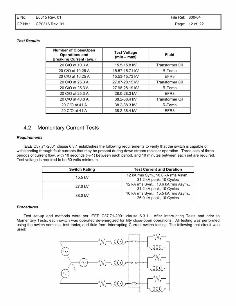
20 C/O at 10.3 A 15.5-15.8 kV Transformer Oil20 C/O at 10.26 A 15.57-15.71 kV R-Temp20 C/O at 10.25 A 15.53-15.73 kV EFR320 C/O at 25.3 A 27.87-28.15 kV Transformer Oil20 C/O at 25.3 A 27.98-28.19 kV R-Temp20 C/O at 25.3 A 28.0-28.3 kV EFR320 C/O at 40.8 A 38.2-38.4 kV Transformer Oil20 C/O at 41 A 38.2-38.3 kV R-Temp20 C/O at 41 A 38.2-38.4 kV EFR3
4.2. Momentary Current Tests
Requirements
IEEE C37.71-2001 clause 6.3.1 establishes the following requirements to verify that the switch is capable ofwithstanding through fault currents that may be present during down stream recloser operation. Three sets of threeperiods of current flow, with 10 seconds (+/-1) between each period, and 10 minutes between each set are required.Test voltage is required to be 50 volts minimum.
Switch Rating Test Current and Duration
15.5 kV 12 kA rms Sym., 18.6 kA rms Asym.,31.2 kA peak, 10 Cycles
27.0 kV 12 kA rms Sym., 18.6 kA rms Asym.,31.2 kA peak, 10 Cycles
38.0 kV 10 kA rms Sym., 15.5 kA rms Asym.,26.0 kA peak, 10 Cycles
Procedures
Test set-up and methods were per IEEE C37.71-2001 clause 6.3.1. After Interrupting Tests and prior toMomentary Tests, each switch was operated de-energized for fifty close-open operations. All testing was performedusing the switch samples, test tanks, and fluid from Interrupting Current switch testing. The following test circuit wasused:
E No: E0315 Rev. 01 File Ref: 800-64
CP No.: CP0316 Rev. 01 Page: 13 of 22
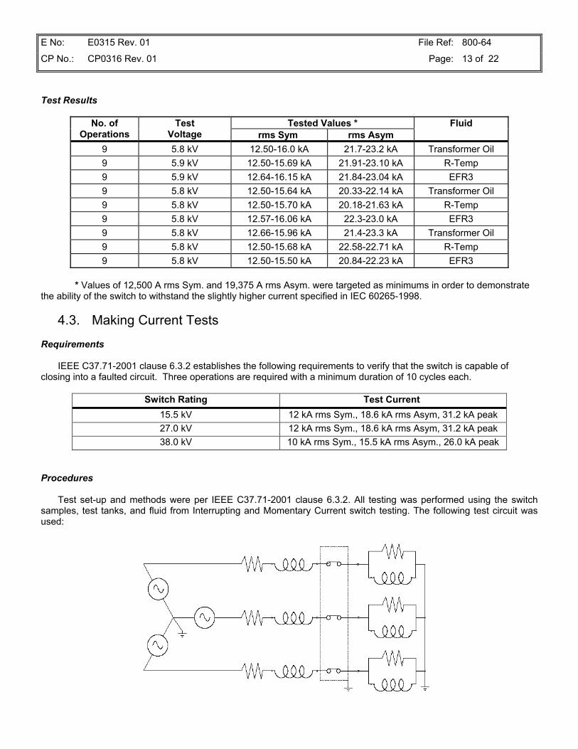
Test Results
Tested Values *No. ofOperations
TestVoltage rms Sym rms Asym
Fluid
9 5.8 kV 12.50-16.0 kA 21.7-23.2 kA Transformer Oil9 5.9 kV 12.50-15.69 kA 21.91-23.10 kA R-Temp9 5.9 kV 12.64-16.15 kA 21.84-23.04 kA EFR39 5.8 kV 12.50-15.64 kA 20.33-22.14 kA Transformer Oil9 5.8 kV 12.50-15.70 kA 20.18-21.63 kA R-Temp9 5.8 kV 12.57-16.06 kA 22.3-23.0 kA EFR39 5.8 kV 12.66-15.96 kA 21.4-23.3 kA Transformer Oil9 5.8 kV 12.50-15.68 kA 22.58-22.71 kA R-Temp9 5.8 kV 12.50-15.50 kA 20.84-22.23 kA EFR3
* Values of 12,500 A rms Sym. and 19,375 A rms Asym. were targeted as minimums in order to demonstratethe ability of the switch to withstand the slightly higher current specified in IEC 60265-1998.
4.3. Making Current Tests
Requirements
IEEE C37.71-2001 clause 6.3.2 establishes the following requirements to verify that the switch is capable ofclosing into a faulted circuit. Three operations are required with a minimum duration of 10 cycles each.
Switch Rating Test Current 15.5 kV 12 kA rms Sym., 18.6 kA rms Asym, 31.2 kA peak27.0 kV 12 kA rms Sym., 18.6 kA rms Asym, 31.2 kA peak38.0 kV 10 kA rms Sym., 15.5 kA rms Asym., 26.0 kA peak
Procedures
Test set-up and methods were per IEEE C37.71-2001 clause 6.3.2. All testing was performed using the switchsamples, test tanks, and fluid from Interrupting and Momentary Current switch testing. The following test circuit wasused:

E No: E0315 Rev. 01 File Ref: 800-64
CP No.: CP0316 Rev. 01 Page: 14 of 22
Test Results
No. ofOperations
Minimum Cyclesof Operation
DurationTest
VoltageTested Current
Value * Fluid
3 10 15.80 kV 12.54 kA Transformer Oil
3 10 15.63 kV 12.53 kA R-Temp
3 10 15.63 kV 12.53 kA EFR3
3 10 28.16 kV 12.60 kA Transformer Oil
3 10 28.16 kV 12.60 kA R-Temp
3 10 28.03 kV 12.62 kA EFR3
3 10 38.15 kV 12.58 kA Transformer Oil
3 10 38.15 kV 12.58 kA R-Temp
3 10 38.15 kV 12.58 kA EFR3
* Values of 12,500 A rms Sym. and 19,375 A rms Asym. were targeted as minimums in order to demonstratethe ability of the switch to withstand the slightly higher current specified in IEC 60265-1998.
4.4. AC Withstand Tests
Requirements
IEEE C37.71-2001 Table 1, column 3 defines the withstand test voltage requirements to verify the low frequencydielectric capabilities of the design.
Switch Rating4.4.1
New Switch SampleTest Voltage
4.4.2Aged Switch Sample
Test Voltage 15.5 kV 35 kV rms 34 kV rms 27.0 kV 60 kV rms 40 kV rms38.0 kV 70 kV rms 50 kV rms
Procedures
4.4.1Test set-up and methods were per IEEE C37.71-2001 clause 6.4.5. Samples were tested prior to any aging tests
in clean fluid and then again after switching tests. Each sample was tested with the contacts open and with thecontacts closed. The tank was grounded for all tests. When the contacts were closed the A and C phases (the frontand back deck) were energized and the B phase (the center deck) was grounded. Voltage was applied for oneminute. When the contacts were open, one side of the switch had contacts A and C energized and contact Bgrounded, and the other side had A and C grounded with B energized. Again, the voltage was applied for one minute.
4.4.2After completing the switching tests detailed in Section 4.1, 50 additional close-open operations, the momentary
current tests detailed in Section 4.2 and the making tests per Section 4.3, the applied voltage tests described abovewere repeated. While the standards allowed for the test voltage to be reduced for the aged switch samples, the testswere conducted to the higher test voltages required for new switch samples. The same fluid used in the switching,momentary and making tests was also used for these tests.

E No: E0315 Rev. 01 File Ref: 800-64
CP No.: CP0316 Rev. 01 Page: 15 of 22
Test Results
4.4.1
Phase-to Earth TestVoltage
Phase-to-PhaseTest Voltage
Across Open ContactsTest Voltage
Across IsolatingDistance Test Voltage
70.2 kV rms 70.2 kV rms 70.2 kV rms 70.2 kV rms
4.4.2
All switch samples successfully passed the 50 open/close operations test.
SwitchRating Tested Value Fluid
35 kV Transformer Oil60 kV R-Temp15.5 kV60 kV EFR360 kV Transformer Oil60 kV R-Temp27.0 kV60 kV EFR370 kV Transformer Oil70 kV R-Temp38.0 kV70 kV EFR3
4.5. Thermal Tests
Requirements
IEEE C37.71-2001 clauses 5.3.1 and 5.3.2 establish the temperature rise limits for testing of new samples.Clause 6.5.5 further requires “aged” switch samples to operate at continuous rated current and a stable contacttemperature after being subjected to the interrupting, momentary current, and making current switch testing.
Procedures
Test conditions and procedures were per IEEE C37.71-2001 clause 6.5. Samples were mounted into a fluid-filledtank, following recommended installation practices. Thermocouples were added to the incoming cable, the terminationconnection, the incoming stationary contact, the switchblade, the outgoing terminal, the outgoing terminationconnection and the outgoing lead. Thermocouples were also placed in the oil 2” below the current carrying membersand in the ambient air. For new switch samples, Table 4 of standard IEEE C37.71 defines the continuous currenttemperature rise limits of current carrying parts. Successful completion of the test requires the temperature rise tostabilize at a value below those published in the table.
For aged switch samples there are no temperature rise constraints specified by the standards. Rather, successfulcompletion of the test requires the temperature rise to stabilize. A stable temperature is defined as no change intemperature for three consecutive readings at 30-minute intervals.

E No: E0315 Rev. 01 File Ref: 800-64
CP No.: CP0316 Rev. 01 Page: 16 of 22
Test Results – Continuous Current – New Switch Samples
ContactTemp Rise
BladeTemp Rise
TerminalTemp Rise Fluid
Rise over top oil 8.3°C 7.0°C 0.8°CRise over ambient 34.1°C 32.8°C 26.6°C
Transformer Oil
Current was 630 Amperes.
Test Results – Thermal Runaway – Aged Switch Samples
ContactTemp Rise
ConnectionTemp Rise
TerminalTemp Rise Fluid
7.3°C 8.8°C 4.0°C Transformer Oil12.8°C 15.3°C 8.7°C R-Temp9.4°C 8.9°C 4.7°C EFR39.1°C 8.8°C 4.1°C Transformer Oil13.6°C 13.7°C 7.3°C R-Temp10.3°C 10.3°C 4.1°C EFR38.3°C 9.1°C 4.5°C Transformer Oil11.1°C 13.7°C 7.4°C R-Temp13.2°C 13.2°C 6.4°C EFR3
All switches stabilized within 24 hours. Current was 630 Amperes. Temperature rises shown are over top oiltemperature.
4.6. Mechanical Operations Tests
Requirements
IEEE C37.71-2001 clause 6.6 requires the switch sample to withstand 200 opening and closing operations withoutmaintenance or replacement of any parts or components. It is performed after completion of the thermal runaway test,which in turn is done after completion of all other electrical and mechanical aging tests.
After completion, the switch should be capable of carrying rated current as evidenced by resistancemeasurements. The maximum resistance allowed in Cooper Power Systems internal production process is 240 micro-ohms. The switch must also be capable of passing the 60 Hertz Withstand voltage in Table, column 4. The 15.5 kVclass switches require a withstand of 34 kV, the 27 kV class require 40 kV and the 38 kV require 50 kV.
Procedures
Test conditions and procedures were per IEEE C37.71-2001 clause 6.6. The same procedure as in Section 4.4was employed.
Test Results
All switches were operated deenergized for 200 open-close operations. All switches subsequently passed ACWithstand and Resistance tests.

E No: E0315 Rev. 01 File Ref: 800-64
CP No.: CP0316 Rev. 01 Page: 17 of 22
SwitchRating
Current InterchangeResistance (Maximum)
AC WithstandTested Voltage Fluid
89 micro-ohms 60.2 kV * Transformer Oil139 micro-ohms 60.2 kV * R-Temp15.5 kV127 micro-ohms 60.2 kV * EFR3136 micro-ohms 60.2 kV * Transformer Oil190 micro-ohms 60.2 kV * R-Temp27.0 kV88 micro-ohms 60.2 kV * EFR3
133 micro-ohms 60.2 kV Transformer Oil102 micro-ohms 60.2 kV R-Temp38.0 kV158 micro-ohms 60.2 kV EFR3
* All switches were tested to the required value for a 38 kV switch.
4.7. Impulse Withstand Tests
Requirements
IEEE C37.71-2001 Table 1, column 2 defines the 1.2 x 50 microsecond waveform withstand test voltagerequirements to verify the high frequency dielectric capabilities of the design. Additionally, IEEE C57.12.00 – 2000Table 5 defines the chopped wave withstand test voltage requirements.
Switch Rating 1.2 x 50µ SecPeak Test Voltage
Chopped WavePeak Test Voltage
15.5 kV 95 kV rms 110 kV rms 27.0 kV 125 kV rms 145 kV rms38.0 kV 150 kV rms 175 kV rms
Procedures
Test set-up and methods were per IEEE C37.71-2001 clause 6.4. Samples were tested prior to aging tests inclean fluid. Each sample was tested with the contacts open and with the contacts closed. The tank was grounded forall tests. With the contacts open, voltage was applied to contacts A and C phases (first and third deck) on one side ofthe switch, with B phase (second deck) grounded. On the other side of the switch, A and C contacts were groundedand voltage was applied to B. Three positive polarity and three negative polarity impulses were applied.
With the contacts closed, voltage was applied to A and C phases with the B phase grounded and the tank and theswitch mechanism grounded. Three positive polarity and three negative polarity impulses were applied.
All models of the switch share the same dielectric design features (materials, spacing, etc.). Consequently thedesign was verified to its highest rating and testing conducted at this rating only.
Test Results
1.2 x 50µ SecTested Value
Chopped WaveTested Value Fluid
169.6 kV 196.0 Transformer Oil

E No: E0315 Rev. 01 File Ref: 800-64
CP No.: CP0316 Rev. 01 Page: 18 of 22
4.8. DC Withstand Tests
Requirements
IEEE C37.71-2001 Table 1, column 5 defines the withstand test voltage requirements to verify that the switch iscapable of withstanding the DC test voltages that may be applied to installed cable systems.
Switch Rating Test Voltage 15.5 kV 53 kV 27.0 kV 78 kV 38.0 kV 103 kV
Procedures
Test set-up and methods were per IEEE C37.71-2001 clause 6.8. Test voltage was applied and held for 15minutes at 103 kV. The test tank was grounded, as was the switch stored energy mechanism. Three separate testswere done:
1) With the contacts open, one side of the switch was energized with the contacts on the other sidegrounded.
2) With the contacts open, A and C phases (first and third deck) on one side of the switch and B phase(second deck) on the other side were energized with all the other contacts grounded.
3) With the contacts closed, A and C phases were energized and B phase grounded.
All models of the switch share the same dielectric design features (materials, spacing, etc.). Consequently thedesign was verified to its highest rating and testing conducted at this rating only.
Test Results
TestedValue Fluid
103 kV Transformer Oil
4.9. One-second Current Test
Requirements
IEEE C37.71-2001 clause 6.3.3 requires the switch to withstand a single current carrying test of a minimum ofone-second duration at the rated momentary current level of 12.0 kA. After completion, the switch must be operableand capable of carrying rated current (630A) within rated temperature maximum of 75°C.
Procedures
Leads were connected to wire the A, B, and C phase together in series. With the contacts in the closed position,12,500 amperes of current were passed through the circuit for one second. A value of 12,500 A was used in order todemonstrate the ability of the switch to withstand the slightly higher current specified in IEC 60265-1998. A two-second duration was used to satisfy a specific user request.

E No: E0315 Rev. 01 File Ref: 800-64
CP No.: CP0316 Rev. 01 Page: 19 of 22
Results
TestVoltage
CurrentDuration
Momentary TestCurrent
Heat RunCurrent
Switch MaxTemp Fluid
240 V 2 sec 12,740 A 630 A 59.4°C Transformer Oil
At the conclusion of the test, the switch was operated 200 times mechanically and subjected to a heat run toensure that the current carrying ratings were not affected.
4.10. Pressure Test
Requirements
IEEE C37.71-2001 clause 6.9 requires that the switch samples maintain its tank seal and remain operable afterbeing subjected to positive and negative tank pressures. Further, the product standards for padmounted transformers(IEEE C57.12.22-1993, IEEE C57.12.25-1990, and IEEE C57.12.26-1992) require the tank to remained sealedthrough an operating pressure range of -7 psig to +12 psig. The bottom of this range is established by calculating theinternal tank pressure when the fluid temperature is -5°C. The cracking pressure of the pressure relief deviceestablished the top of this range.
Procedure
Samples of the Bolt-in, Ring Mount and Quick Mount switches were installed into tanks in the horizontal positionusing recommended mounting procedure. Internal tank pressures of -15 psig and +15 psig were used. Soapsolutions, chalk and observations for liquids leaking from shafts or gasketed surface were used to determine sealintegrity. Switches were operated while the tanks were at pressure extremes and after the pressure was relieved tocheck for any untoward effects of the pressurization.
Results
There was no sign of leakage. Switches operated normally during positive and negative tank pressure extremesand after the pressures were relieved.
4.11. Vibration Test
Requirements
The industry standards for HV switches do not define test requirements for vibration testing. However, utilizingmethods developed for military and automotive applications, a procedure has been developed to test the product atfrequencies and accelerations that can be anticipated as well as identifying and testing at the product’s resonantfrequency. The switch has been designed for horizontal mounting in a fluid filled tank. After installation in the tank, itmust survive the forces associated with handling and shipping that tank.
Procedures
A switch sample with Quick Mount mounting system was installed in a 18”H x 12”W x 22”D test tank.Accelerometers were mounted on the switch shaft and 2-pound weights were secured to each of the switch terminals.The tank was filled with water and sealed. The tank and switch were secured to a vibration table and a series ofaccelerations applied. Upon completion of the tests, the tank seal was pressure tested to 15 psig, the switch tested formechanical operation and visually inspected.

E No: E0315 Rev. 01 File Ref: 800-64
CP No.: CP0316 Rev. 01 Page: 20 of 22
Sine Sweep Test – Input vertical acceleration of 0.5 g (g= 32.16 ft/sec2) at frequencies from 5 Hz through 60 Hz todetermine the resonant (highest output acceleration) frequency.
Resonant Frequency Endurance Test – Using the resonant frequency vibration test at the following accelerationsand durations:
Input Acceleration Duration0.5 g 100,000 cycles0.75 g 100,000 cycles1.0 g 100,000 cycles
High Frequency Endurance Test – The following frequencies, accelerations and durations were used:
Input Acceleration Frequency Duration0.5 g 120 Hz 2,000,000 cycles0.5 g 240 Hz 2,000,000 cycles0.5 g 360 Hz 2,000,000 cycles
Results
The resonant frequency was found to be 33 Hz. After all testing was completed, the tank was pressure tested at15 psig for 24 hours and no leaks were found. The switch sample was mechanically tested and visually inspected andno anomalies were found. Test results are documented in test report AA-02-055-4G and Datasyst Engineering andTesting Services Project Report C115-10497.
4.12. Packaging Test
Requirements
The industry standards do not include this test regimen. However, these switches will be supplied to transformermanufacturers throughout the world. Consequently, the switch must be packaged to survive shipment to thesemanufacturers.
Procedure
A three phase, Quick Mount, Selector blade switch assembly and packaged hardware (handle, mounting nut,gasket, etc.) were packaged at the production facility and sent to Great Northern Corporation (GNC) for vibration,handling, and drop testing. The tests were conducted in accordance with ISTA (International Safe Transit Association)procedure 1A for packaged products weighing 68 kg or less.
Results
The entire assembly, including packaged handle hardware was tested at GNC’s ISTA certified lab and passed thetest regimen with no signs of damage. Test results are documented in test report AA-03-017-4T.

E No: E0315 Rev. 01 File Ref: 800-64
CP No.: CP0316 Rev. 01 Page: 21 of 22
4.13. Operating Force Test
Requirements
The industry standards do not include these test regimens. Cooper Power Systems has developed internalrequirements that the switch must require less than 25 foot-pounds (34 N m) of torque to move from one position tothe next.
Procedure
One sample each of three phase Selector Blade, V-Blade, and T-Blade switches were horizontally mounted in anempty test tank using published installation instructions. A specially designed socket was placed over the operatinghandle. Torque was applied and measured with a digital recording torque wrench. Operating forces were checkedwhile operating the switch as slowly as possible and also as rapidly as possible.
Results
When operated very slowly, the switch requires 18 to 28 foot-pounds (24 to 38 Newton-meters) of torque, which iswell within normal ergonomic limits. When operated at a higher speed typical of that observed when utility personneloperate the switch, the operating force falls to 15 to 25 foot-pounds (20 to 34 Newton-meters).
4.14. Operating Travel Test
Requirements
The industry standards do not include this test regimen. Cooper Power Systems has established specificationsthat require that the switch must move from one position to the next with less than a 135° rotation.
Procedure
Using the same test set-up and a sample from the Operating Force Test, a protractor was centered on the tankwall used to mount he switch. As the switch was operated, the angular displacement needed to cause actuation wasnoted and recorded.
Results
The switch typically requires 115° to 125° to switch from one position to the next.
Quality fromR-Temp and Envirotemp are registered trademarks of Cooper Industries, Inc. Cooper IndustriesFR3 is a trademark of Cooper Industries, Inc. P.O. Box 1640, Waukesha, WI 53187

E No: E0315 Rev. 01 File Ref: 800-64
CP No.: CP0316 Rev. 01 Page: 22 of 22
REVISION TABLE
REVISIONNO. DATE WHAT WAS ADDED/CHANGED
1 12/3/04 Section 4.6 Mechanical Operations Tests, changed milli-ohms to micro-ohms in text and table