Embed Size (px)
Citation preview
www.sandpiperpump.com
HDB3/HDB4 Heavy Duty Ball Valve Design Level 4
Quality SystemISO9001 Certified
Environmental Management System ISO14001 Certified
Certified Quality
Warren Rupp, Inc.A Unit of IDEX Corporation
800 N. Main St., Mansfield, Ohio 44902 USA Telephone (419) 524.8388
Fax (419) 522.7867www.SAndpiperpUMp.cOM
©2013 warren rupp, inc.
36.40 925
18.63 473
26.06 662
AIR INLET3/4" NPT
19.66 499
32.65 829
1.22 3113.50 343
16.25 413
SUCTION PORT3" 150# ANSI FLANGE4X .75 HOLES EQUALLYSPACED ON A 6.00 B.C.
DISCHARGE PORT3" 150# ANSI FLANGE4X .75 HOLES EQUALLYSPACED ON A 6.00 B.C.
11.00 279
15.00 381
17.63 448
8X .56MOUNTING HOLE
AIR EXHAUST1" NPT
6.26 159
18.62 473
19.25 489
31.19 792
26.06 662
DISCHARGE PORT4" 150# ANSI FLANGE8X .75 HOLES EQUALLYSPACED ON A 7.50 B.C.
SUCTION PORT4" 150# ANSI FLANGE8X .75 HOLES EQUALLYSPACED ON A 6.00 B.C.
AIR INLET3/4" NPT 18.32 465
17.50 445
27.07 688
1.18 30
17.62 448
8X .56 14MOUNTING HOLE
11.00 279
15.00 381
AIR EXHAUST1" NPT
SERVICE & OPERATING MANUALOriginal Instructions
1: p
UMp
Spec
S2:
inST
AL &
Op
3: e
Xp V
iew
4: A
ir e
nd5:
weT
end
6: O
pTiO
nAL
7: w
ArrA
nTY
hdb3dl4sm-rev0313
www.sandpiperpump.com
IMPORTANT
Read the safety warnings and instructions in this manual before pump installation and start-up. Failure to comply with the recommendations stated in this manual could damage the pump and void factory warranty.
When used for toxic or aggressive fluids, the pump should always be flushed clean prior to disassembly.
Airborne particles and loud noise hazards. Wear eye and ear protection.
Before maintenance or repair, shut off the compressed air line, bleed the pressure, and disconnect the air line from the pump. Be certain that approved eye protection and protective clothing are worn at all times. Failure to follow these recommendations may result in serious injury or death.
To be fully groundable, the pumps must be ATeX compliant. refer to the nomenclature page for ordering information.
Optional 8 foot long (244 centimeters) Ground Strap is available for easy ground connection.
To reduce the risk of static electrical sparking, this pump must be grounded. Check the local electrical code for detailed grounding instruction and the type of equipment required.
Refer to nomenclature page for ordering information.
When the pump is used for materials that tend to settle out or solidify, the pump should be flushed after each use to prevent damage. In freezing temperatures the pump should be completely drained between uses.
Before pump operation, inspect all fasteners for loosening caused by gasket creep. Retighten loose fasteners to prevent leakage. Follow recommended torques stated in this manual.
CAUTION
WARNING
Nonmetallic pumps and plastic components are not UV stabilized. Ultraviolet radiation can damage these parts and negatively affect material properties. Do not expose to UV light for extended periods of time.
Model HdB3/HdB4
In the event of diaphragm rupture, pumped material may enter the air end of the pump, and be discharged into the atmosphere. If pumping a product that is hazardous or toxic, the air exhaust must be piped to an appropriate area for safe containment.
This pump is pressurized internally with air pressure during operation. Make certain that all fasteners are in good condition and are reinstalled properly during reassembly.
Take action to prevent static sparking. Fire or explosion can result, especially when handling flammable liquids. The pump, piping, valves, containers and other miscellaneous equipment must be properly grounded.
Safety Information
Grounding the Pump
WARNINGTake action to prevent static sparking. Fire or explosion can result, especially when handling flammable liquids. The pump, piping, valves, containers or other miscellaneous equipment must be grounded.
UNIVERSAL ALL AODD
hdb3dl4sm-rev0313
www.sandpiperpump.com Model HdB3/HdB4
Table of Contents
SECTION 1: PumP SPECIfICaTIONS ................1 •ExplanationofNomenclature •Performance •Materials •DimensionalDrawings
SECTION 2: INSTallaTION & OPEraTION ......7 •PrincipleofPumpOperation •RecommendedInstallationGuide •TroubleshootingGuide
SECTION 3: ExPlOdEd VIEw .........................10 •CompositeRepairPartsDrawing •CompositeRepairPartsList •MaterialCodes
SECTION 4: aIr ENd .......................................14 •AirDistributionValveAssembly •AirValvewithStrokeIndicatorAssembly •PilotValveAssembly •IntermediateAssembly
SECTION 7: warraNTy & CErTIfICaTES ....17 •Warranty •ECDeclarationofConformity-Machinery •ECDeclarationofConformity-ATEX •ECSummaryofMarkings
MODEL SPECIFIC
1: p
UMp
Spec
S2:
inST
AL &
Op
3: e
Xp V
iew
4: A
ir e
nd5:
weT
end
6: O
pTiO
nAL
7: w
ArrA
nTY
hdb3dl4sm-rev0313
www.sandpiperpump.com1 • Model HdB3/HdB4
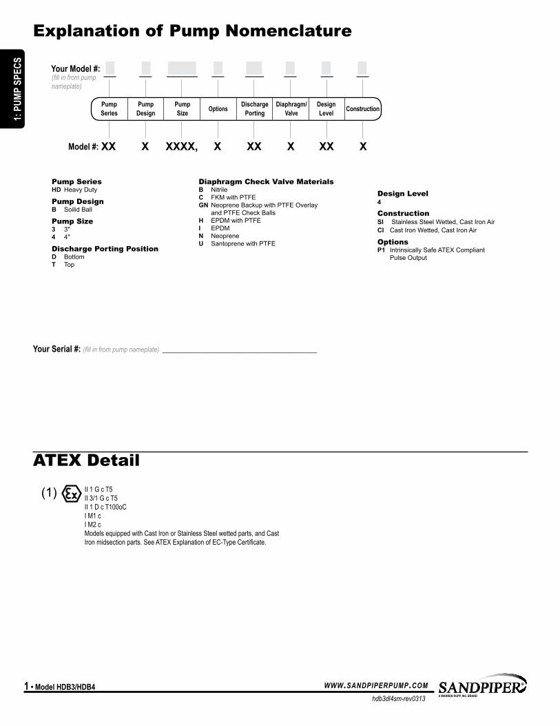
Explanation of Pump Nomenclature
aTEx detail
(1) II 2GD T5II1GcT5II3/1GcT5II1DcT100oCIM1cIM2cModelsequippedwithCastIronorStainlessSteelwettedparts,andCastIronmidsectionparts.SeeATEXExplanationofEC-TypeCertificate.
diaphragm Check Valve materials B Nitrile C FKM with PTFE GN Neoprene Backup with PTFE Overlay and PTFE Check Balls H EPDM with PTFE I EPDM N Neoprene U Santoprene with PTFE
design level 4
Construction SI Stainless Steel Wetted, Cast Iron Air CI Cast Iron Wetted, Cast Iron Air
Options P1 Intrinsically Safe ATEX Compliant Pulse Output
Pump Series HD Heavy Duty
Pump design B Soilid Ball
Pump Size 3 3" 4 4"
discharge Porting Position D Bottom T Top
Your Serial #: (fill in from pump nameplate) _____________________________________
__ __ _____ __ ___ __ __ __
pump pump pump Options discharge diaphragm/ design construction Series design Size porting Valve Level
XX X XXXX, X XX X XX XModel #:
(fill in from pump nameplate)
Your Model #:
MODEL SPECIFIC
1: P
UMP
SPEC
S
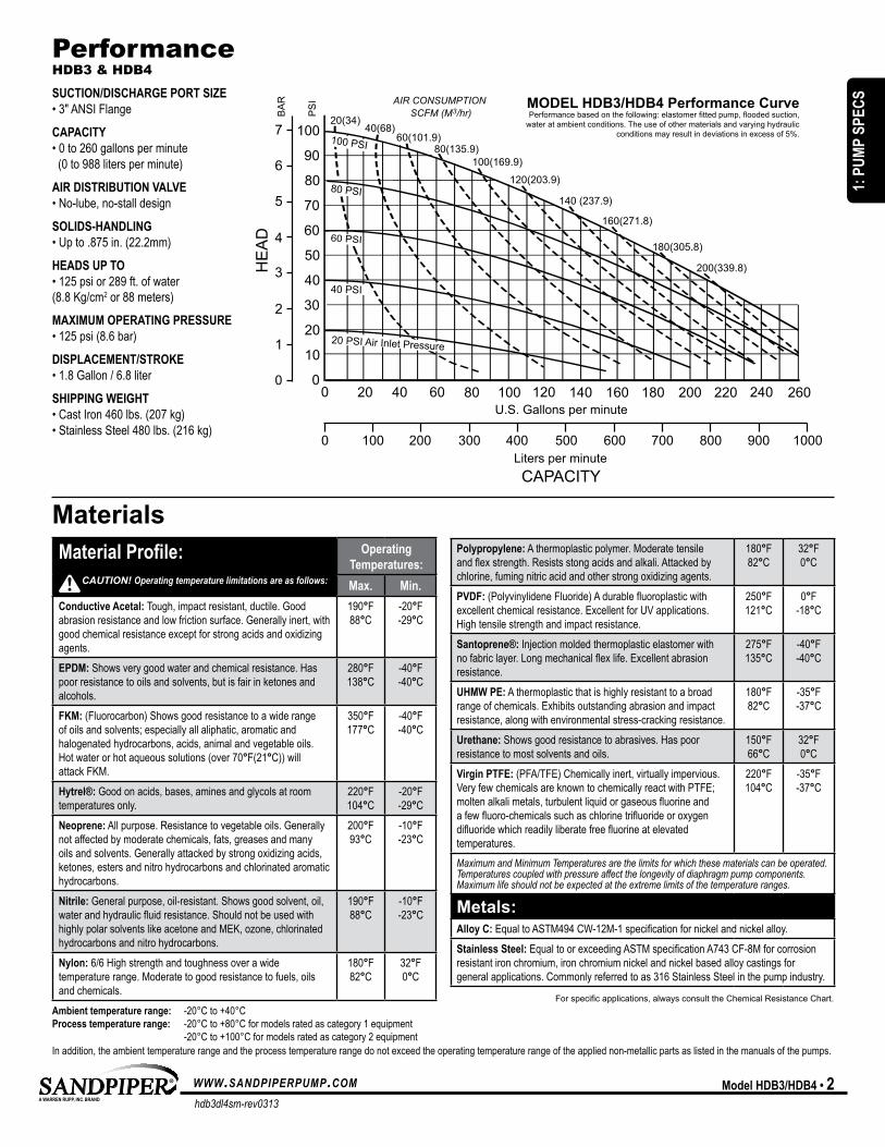
20(34)40(68)
60(101.9)80(135.9)
100(169.9)
120(203.9)
140 (237.9)
160(271.8)
180(305.8)
200(339.8)
90
80
70
60
50
40
30
20
10
00 20 40 60 80 100 120 140 160 180 200 220 240 260
100 PSI
80 PSI
60 PSI
40 PSI
100
0 100 200 300 400 500 600 700 800 900 1000
BA
R
0
1
2
3
4
5
6
7
PS
I
20 PSI Air Inlet Pressure
Liters per minute
U.S. Gallons per minute
CAPACITY
AIR CONSUMPTION SCFM (M3/hr)
HE
AD
MODEL HDB3/HDB4 Performance CurvePerformance based on the following: elastomer fitted pump, flooded suction,
water at ambient conditions. The use of other materials and varying hydraulicconditions may result in deviations in excess of 5%.
hdb3dl4sm-rev0313
www.sandpiperpump.com Model HdB3/HdB4 • 2
PerformanceHdB3 & HdB4
SUcTiOn/diScHArge pOrT Size•3"ANSIFlange
cApAciTY•0to260gallonsperminute(0to988litersperminute)
Air diSTriBUTiOn VALVe•No-lube,no-stalldesign
SOLidS-HAndLing•Upto.875in.(22.2mm)
HeAdS Up TO•125psior289ft.ofwater(8.8Kg/cm2 or 88 meters)
MAXiMUM OperATing preSSUre•125psi(8.6bar)
diSpLAceMenT/STrOke•1.8Gallon/6.8liter
SHipping weigHT•CastIron460lbs.(207kg)•StainlessSteel480lbs.(216kg)
MaterialsMaterial profile: Operating
Temperatures:Max. Min.
conductive Acetal: Tough, impact resistant, ductile. Good abrasionresistanceandlowfrictionsurface.Generallyinert,withgoodchemicalresistanceexceptforstrongacidsandoxidizingagents.
190°F88°C
-20°F-29°C
epdM:Showsverygoodwaterandchemicalresistance.Haspoor resistance to oils and solvents, but is fair in ketones and alcohols.
280°F138°C
-40°F-40°C
FkM:(Fluorocarbon)Showsgoodresistancetoawiderange of oils and solvents; especially all aliphatic, aromatic and halogenated hydrocarbons, acids, animal and vegetable oils. Hotwaterorhotaqueoussolutions(over70°F(21°C))will attackFKM.
350°F177°C
-40°F-40°C
Hytrel®: Good on acids, bases, amines and glycols at room temperatures only.
220°F104°C
-20°F-29°C
neoprene:Allpurpose.Resistancetovegetableoils.Generallynot affected by moderate chemicals, fats, greases and many oilsandsolvents.Generallyattackedbystrongoxidizingacids,ketones, esters and nitro hydrocarbons and chlorinated aromatic hydrocarbons.
200°F93°C
-10°F-23°C
nitrile: Generalpurpose,oil-resistant.Showsgoodsolvent,oil,waterandhydraulicfluidresistance.ShouldnotbeusedwithhighlypolarsolventslikeacetoneandMEK,ozone,chlorinatedhydrocarbons and nitro hydrocarbons.
190°F88°C
-10°F-23°C
nylon: 6/6Highstrengthandtoughnessoverawide temperaturerange.Moderatetogoodresistancetofuels,oilsand chemicals.
180°F82°C
32°F0°C
polypropylene:Athermoplasticpolymer.Moderatetensileandflexstrength.Resistsstongacidsandalkali.Attackedbychlorine,fumingnitricacidandotherstrongoxidizingagents.
180°F82°C
32°F0°C
pVdF:(PolyvinylideneFluoride)Adurablefluoroplasticwithexcellentchemicalresistance.ExcellentforUVapplications.Hightensilestrengthandimpactresistance.
250°F121°C
0°F-18°C
Santoprene®:Injectionmoldedthermoplasticelastomerwithnofabriclayer.Longmechanicalflexlife.Excellentabrasionresistance.
275°F135°C
-40°F-40°C
UHMw pe:Athermoplasticthatishighlyresistanttoabroadrangeofchemicals.Exhibitsoutstandingabrasionandimpactresistance,alongwithenvironmentalstress-crackingresistance.
180°F82°C
-35°F-37°C
Urethane:Showsgoodresistancetoabrasives.Haspoorresistance to most solvents and oils.
150°F66°C
32°F0°C
Virgin pTFe:(PFA/TFE)Chemicallyinert,virtuallyimpervious.VeryfewchemicalsareknowntochemicallyreactwithPTFE;moltenalkalimetals,turbulentliquidorgaseousfluorineandafewfluoro-chemicalssuchaschlorinetrifluorideoroxygendifluoridewhichreadilyliberatefreefluorineatelevated temperatures.
220°F104°C
-35°F-37°C
Maximum and Minimum Temperatures are the limits for which these materials can be operated. Temperatures coupled with pressure affect the longevity of diaphragm pump components. Maximum life should not be expected at the extreme limits of the temperature ranges.
Metals:Alloy c:EqualtoASTM494CW-12M-1specificationfornickelandnickelalloy.Stainless Steel: EqualtoorexceedingASTMspecificationA743CF-8Mforcorrosionresistant iron chromium, iron chromium nickel and nickel based alloy castings for generalapplications.Commonlyreferredtoas316StainlessSteelinthepumpindustry.
For specific applications, always consult the Chemical Resistance Chart.
CAUTION! Operating temperature limitations are as follows:
Ambient temperature range: -20°Cto+40°Cprocess temperature range: -20°Cto+80°Cformodelsratedascategory1equipment -20°Cto+100°Cformodelsratedascategory2equipmentInaddition,theambienttemperaturerangeandtheprocesstemperaturerangedonotexceedtheoperatingtemperaturerangeoftheappliednon-metallicpartsaslistedinthemanualsofthepumps.
aTEx detail
MODEL SPECIFIC UNIVERSAL ALL AODD
1: P
UMP
SPEC
S
hdb3dl4sm-rev0313
www.sandpiperpump.com3 • Model HdB3/HdB4
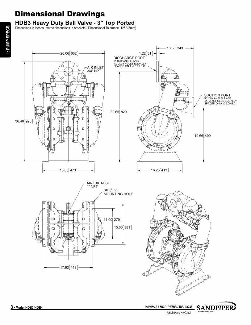
HDB3 Heavy Duty Ball Valve - 3" Top Ported Dimensionsininches(metricdimensionsinbrackets).DimensionalTolerance.125"(3mm).
dimensional drawings
36.40 925
18.63 473
26.06 662
AIR INLET3/4" NPT
19.66 499
32.65 829
1.22 3113.50 343
16.25 413
SUCTION PORT3" 150# ANSI FLANGE4X .75 HOLES EQUALLYSPACED ON A 6.00 B.C.
DISCHARGE PORT3" 150# ANSI FLANGE4X .75 HOLES EQUALLYSPACED ON A 6.00 B.C.
11.00 279
15.00 381
17.63 448
8X .56MOUNTING HOLE
AIR EXHAUST1" NPT
MODEL SPECIFIC
1: P
UMP
SPEC
S
hdb3dl4sm-rev0313
www.sandpiperpump.com Model HdB3/HdB4 • 4
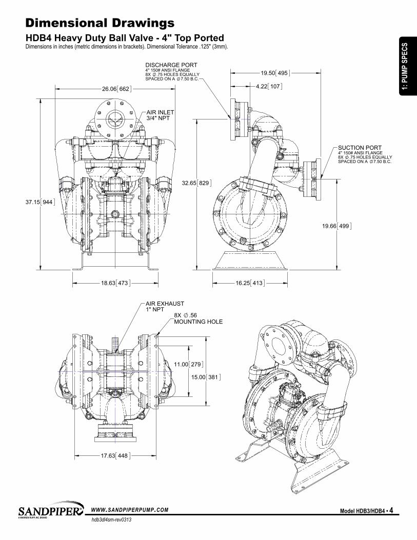
HDB4 Heavy Duty Ball Valve - 4" Top Ported Dimensionsininches(metricdimensionsinbrackets).DimensionalTolerance.125"(3mm).
dimensional drawings
18.63 473
37.15 944
26.06 662
AIR INLET3/4" NPT
19.66 499
32.65 829
16.25 413
4.22 107
19.50 495
SUCTION PORT4" 150# ANSI FLANGE8X .75 HOLES EQUALLYSPACED ON A 7.50 B.C.
DISCHARGE PORT4" 150# ANSI FLANGE8X .75 HOLES EQUALLYSPACED ON A 7.50 B.C.
11.00 279
15.00 381
17.63 448
8X .56MOUNTING HOLE
AIR EXHAUST1" NPT
1: P
UMP
SPEC
S
hdb3dl4sm-rev0313
www.sandpiperpump.com5 • Model HdB3/HdB4
HDB3 Heavy Duty Ball Valve - 3" Bottom Ported Dimensionsininches(metricdimensionsinbrackets).DimensionalTolerance.125"(3mm).
dimensional drawings
6.26 159
18.62 473
19.25 489
31.19 792
26.06 662
DISCHARGE PORT3" 150# ANSI FLANGE4X .75 HOLES EQUALLYSPACED ON A 6.00 B.C.
SUCTION PORT3" 150# ANSI FLANGE4X .75 HOLES EQUALLYSPACED ON A 6.00 B.C.
AIR INLET3/4" NPT
31.07 789
15.32 389
1.82 46
24.07 611
17.50 445
17.62 448
8X .56 14MOUNTING HOLE
11.00 279
15.00 381
AIR EXHAUST1" NPT
1: P
UMP
SPEC
S
hdb3dl4sm-rev0313
www.sandpiperpump.com Model HdB3/HdB4 • 6
HDB4 Heavy Duty Ball Valve - 4" Bottom Ported Dimensionsininches(metricdimensionsinbrackets).DimensionalTolerance.125"(3mm).
dimensional drawings
6.26 159
18.62 473
19.25 489
31.19 792
26.06 662
DISCHARGE PORT4" 150# ANSI FLANGE8X .75 HOLES EQUALLYSPACED ON A 7.50 B.C.
SUCTION PORT4" 150# ANSI FLANGE8X .75 HOLES EQUALLYSPACED ON A 6.00 B.C.
AIR INLET3/4" NPT 18.32 465
17.50 445
27.07 688
1.18 30
17.62 448
8X .56 14MOUNTING HOLE
11.00 279
15.00 381
AIR EXHAUST1" NPT
1: P
UMP
SPEC
S
hdb3dl4sm-rev0313
www.sandpiperpump.com7 • Model HdB3/HdB4
Air-OperatedDoubleDiaphragm(AODD)pumpsarepoweredby compressed air, nitrogen or natural gas.
The main directional (air) control valve ① distributes compressedairtoanairchamber,exertinguniformpressureover the inner surface of the diaphragm ②.Atthesametime,theexhaustingair③ from behind the opposite diaphragm isdirectedthroughtheairvalveassembly(s)toanexhaust port ④.
Asinnerchamberpressure(p1)exceedsliquidchamberpressure (p2), the rod ⑤ connected diaphragms shift together creating discharge on one side and suction on the opposite side. The discharged and primed liquid’s directions arecontrolledbythecheckvalves(ballorflap)⑥ orientation.
The pump primes as a result of the suction stroke. The suctionstrokelowersthechamberpressure(p3) increasing the chamber volume. This results in a pressure differential necessary for atmospheric pressure (p4)topushthefluidthrough the suction piping and across the suction side check valveandintotheouterfluidchamber⑦.
Suction (side) stroking also initiates the reciprocating (shifting, stroking or cycling) action of the pump. The suction diaphragm’s movement is mechanically pulled through its stroke.Thediaphragm’sinnerplatemakescontactwithanactuator plunger aligned to shift the pilot signaling valve. Once actuated, the pilot valve sends a pressure signal to the opposite end of the main directional air valve, redirecting the compressed air to the opposite inner chamber.
Principle of Pump Operation
Air Line
discharged Fluid
dischargeStroke Suction
Stroke
primedFluid
SAFE AIREXHAUSTDISPOSALAREA
PUMP INSTALLATION AREA
1" DIAMETER AIREXHAUST PIPING
1" DIAMETER AIREXHAUST PIPING
1" DIAMETER AIREXHAUST PIPING
MUFFLER
LIQUIDLEVEL
SUCTIONLINE
LIQUIDLEVEL
SUCTIONLINE
MUFFLER
MUFFLER
SUBMERGED ILLUSTRATION
Pumpcanbesubmergedifthepumpmaterialsofconstructionarecompatiblewiththeliquidbeingpumped.Theairexhaustmustbepipedabovetheliquidlevel.Whenthepumpedproductsourceisatahigherlevelthanthepump(floodedsuctioncondition),pipetheexhausthigherthantheproductsourcetoprevent siphoning spills.
UNIVERSAL ALL AODD
2: IN
STAL
& O
P

hdb3dl4sm-rev0313
www.sandpiperpump.com Model HdB3/HdB4 • 8
installation And Start-Up Locatethepumpasclosetotheproductbeingpumpedaspossible.Keepthesuctionlinelengthandnumberoffittingstoaminimum.Donotreducethesuctionlinediameter.
Air Supply Connectthepumpairinlettoanairsupplywithsufficientcapacityandpressuretoachievedesiredperformance.Apressureregulatingvalveshouldbeinstalledtoinsureairsupplypressuredoesnotexceedrecommendedlimits.
Air Valve Lubrication TheairdistributionsystemisdesignedtooperateWITHOUTlubrication.Thisisthestandardmodeofoperation.Iflubricationisdesired,installanairlinelubricatorsettodeliveronedropofSAE10non-detergentoilforevery20SCFM(9.4liters/sec.)ofairthepumpconsumes.ConsultthePerformanceCurvetodetermineairconsumption.
Air Line Moisture Waterinthecompressedairsupplymaycauseicingorfreezingoftheexhaustair,causingthepumptocycleerraticallyorstopoperating.Waterintheairsupplycanbereducedbyusingapoint-of-useairdryer.
Air inlet And priming Tostartthepump,slightlyopentheairshut-offvalve.Afterthepumpprimes,theairvalvecanbeopenedtoincreaseairflowasdesired.Ifopeningthevalveincreasescyclingrate,butdoesnotincreasetherateofflow,cavitationhasoccurred.Thevalveshouldbeclosedslightlytoobtainthemostefficientairflowtopumpflowratio.
Surge Suppressor
Shut-Off Valve
Pressure Gauge
Drain PortShut-OffValve
CheckValve
Air Inlet
Discharge
Unregulated AirSupply to Surge
Suppressor
Pipe Connection(Style Optional)
Flexible Connector
Flexible Connector
VacuumGauge
Suction
Shut-Off Valve
Drain Port Pipe Connection(Style Optional)
FlexibleConnector
Air Dryer
Filter RegulatorP/N: 020.V107.000
Note: Pipe weight should not be supported by pump connections.
Muffler(Optional Piped Exhaust)
recommended Installation Guide
Available Accessories: 1. Surge Suppressor 2. Filter/Regulator 3. Air Dryer
1
2
3
Principle of Pump Operation
note: Surge Suppressor and Pipingmustbesupportedaftertheflexibleconnection
CAUTIONThe air exhaust should be piped to an area for safe disposition of the product being pumped, in the event of a diaphragm failure.
UNIVERSAL ALL AODD, EXCEPT FLAP
SUBMERGED ILLUSTRATION
2: IN
STAL
& O
P
hdb3dl4sm-rev0313
www.sandpiperpump.com9 • Model HdB3/HdB4
Troubleshooting Guide
For additional troubleshooting tips contact After Sales Support at [email protected] or 419-524-8388
Symptom: Potential Cause(s): Recommendation(s):pump cycles Once Deadhead(systempressuremeetsorexceedsair
supply pressure).Increasetheinletairpressuretothepump.Pumpisdesignedfor1:1pressureratioatzeroflow. (Doesnotapplytohighpressure2:1units).
Airvalveorintermediategasketsinstalledincorrectly. Installgasketswithholesproperlyaligned.Bent or missing actuator plunger. Remove pilot valve and inspect actuator plungers.
pump will not Operate / cycle
Pumpisoverlubricated. Setlubricatoronlowestpossiblesettingorremove.Unitsaredesignedforlubefreeoperation.Lackofair(linesize,PSI,CFM). Checktheairlinesizeandlength,compressorcapacity(HPvs.cfmrequired).Check air distribution system. Disassembleandinspectmainairdistributionvalve,pilotvalveandpilotvalveactuators.Dischargelineisblockedorcloggedmanifolds. Checkforinadvertentlycloseddischargelinevalves.Cleandischargemanifolds/piping.Deadhead(systempressuremeetsorexceedsairsupply pressure).
Increasetheinletairpressuretothepump.Pumpisdesignedfor1:1pressureratioatzeroflow. (Doesnotapplytohighpressure2:1units).
Blockedairexhaustmuffler. Removemufflerscreen,cleanorde-ice,andre-install.Pumpedfluidinairexhaustmuffler. Disassemblepumpchambers.Inspectfordiaphragmruptureorloosediaphragmplateassembly.Pumpchamberisblocked. Disassembleandinspectwettedchambers.Removeorflushanyobstructions.
pump cycles and will not prime or no Flow
Cavitation on suction side. Check suction condition (move pump closer to product).Checkvalveobstructed.Valveball(s)notseatingproperly or sticking.
Disassemblethewetendofthepumpandmanuallydislodgeobstructioninthecheckvalvepocket. Clean out around valve ball cage and valve seat area. Replace valve ball or valve seat if damaged. Useheaviervalveballmaterial.
Valveball(s)missing(pushedintochamberormanifold).
Wornvalveballorvalveseat.Wornfingersinvalveballcage(replacepart).CheckChemical Resistance Guide for compatibility.
Valveball(s)/seat(s)damagedorattackedbyproduct. Check Chemical Resistance Guide for compatibility.Checkvalveand/orseatiswornorneedsadjusting. Inspectcheckvalvesandseatsforwearandpropersetting.Replaceifnecessary.Suction line is blocked. Removeorflushobstruction.Checkandclearallsuctionscreensorstrainers.Excessivesuctionlift. Forliftsexceeding20’ofliquid,fillingthechamberswithliquidwillprimethepumpinmostcases.Suction side air leakage or air in product. Visuallyinspectallsuction-sidegasketsandpipeconnections.Pumpedfluidinairexhaustmuffler. Disassemblepumpchambers.Inspectfordiaphragmruptureorloosediaphragmplateassembly.
pump cycles running Sluggish / Stalling, Flow Unsatisfactory
Over lubrication. Setlubricatoronlowestpossiblesettingorremove.Unitsaredesignedforlubefreeoperation.Icing. Removemufflerscreen,de-ice,andre-install.Installapointofuseairdrier.Clogged manifolds. Cleanmanifoldstoallowproperairflow.Deadhead(systempressuremeetsorexceedsairsupply pressure).
Increasetheinletairpressuretothepump.Pumpisdesignedfor1:1pressureratioatzeroflow. (Doesnotapplytohighpressure2:1units).
Cavitation on suction side. Check suction (move pump closer to product).Lackofair(linesize,PSI,CFM). Checktheairlinesize,length,compressorcapacity.Excessivesuctionlift. Forliftsexceeding20’ofliquid,fillingthechamberswithliquidwillprimethepumpinmostcases.Airsupplypressureorvolumeexceedssystemhd. Decreaseinletair(press.andvol.)tothepump.Pumpiscavitatingthefluidbyfastcycling.Undersizedsuctionline. Meetorexceedpumpconnections.Restrictiveorundersizedairline. Installalargerairlineandconnection.Suction side air leakage or air in product. Visuallyinspectallsuction-sidegasketsandpipeconnections.Suction line is blocked. Removeorflushobstruction.Checkandclearallsuctionscreensorstrainers.Pumpedfluidinairexhaustmuffler. Disassemblepumpchambers.Inspectfordiaphragmruptureorloosediaphragmplateassembly.Check valve obstructed. Disassemblethewetendofthepumpandmanuallydislodgeobstructioninthecheckvalvepocket.Checkvalveand/orseatiswornorneedsadjusting. Inspectcheckvalvesandseatsforwearandpropersetting.Replaceifnecessary.Entrainedairorvaporlockinchamber(s). Purgechambersthroughtappedchamberventplugs.Purgingthechambersofaircanbedangerous.
product Leaking Through exhaust
Diaphragmfailure,ordiaphragmplatesloose. Replace diaphragms, check for damage and ensure diaphragm plates are tight.Diaphragmstretchedaroundcenterholeorboltholes. Checkforexcessiveinletpressureorairpressure.ConsultChemicalResistanceChartforcompatibility
withproducts,cleaners,temperaturelimitationsandlubrication.premature diaphragm Failure
Cavitation. Enlargepipediameteronsuctionsideofpump.Excessivefloodedsuctionpressure. Movepumpclosertoproduct.Raisepump/placepumpontopoftanktoreduceinletpressure.
InstallBackpressuredevice(Techbulletin41r).Addaccumulationtankorpulsationdampener.Misapplication(chemical/physicalincompatibility). ConsultChemicalResistanceChartforcompatibilitywithproducts,cleaners,temperaturelimitations
and lubrication.Incorrectdiaphragmplatesorplatesonbackwards,installedincorrectlyorworn.
CheckOperatingManualtocheckforcorrectpartandinstallation.Ensureouterplateshavenotbeenworntoasharpedge.
Unbalanced cycling Excessivesuctionlift. Forliftsexceeding20’ofliquid,fillingthechamberswithliquidwillprimethepumpinmostcases.Undersizedsuctionline. Meetorexceedpumpconnections.Pumpedfluidinairexhaustmuffler. Disassemblepumpchambers.Inspectfordiaphragmruptureorloosediaphragmplateassembly.Suction side air leakage or air in product. Visuallyinspectallsuction-sidegasketsandpipeconnections.Check valve obstructed. Disassemblethewetendofthepumpandmanuallydislodgeobstructioninthecheckvalvepocket.Checkvalveand/orseatiswornorneedsadjusting. Inspectcheckvalvesandseatsforwearandpropersetting.Replaceifnecessary.Entrainedairorvaporlockinchamber(s). Purgechambersthroughtappedchamberventplugs.
UNIVERSAL ALL SANDPIPER, EXCEPT FLAP
2: IN
STAL
& O
P
hdb3dl4sm-rev0313
www.sandpiperpump.com Model HdB3/HdB4 • 10
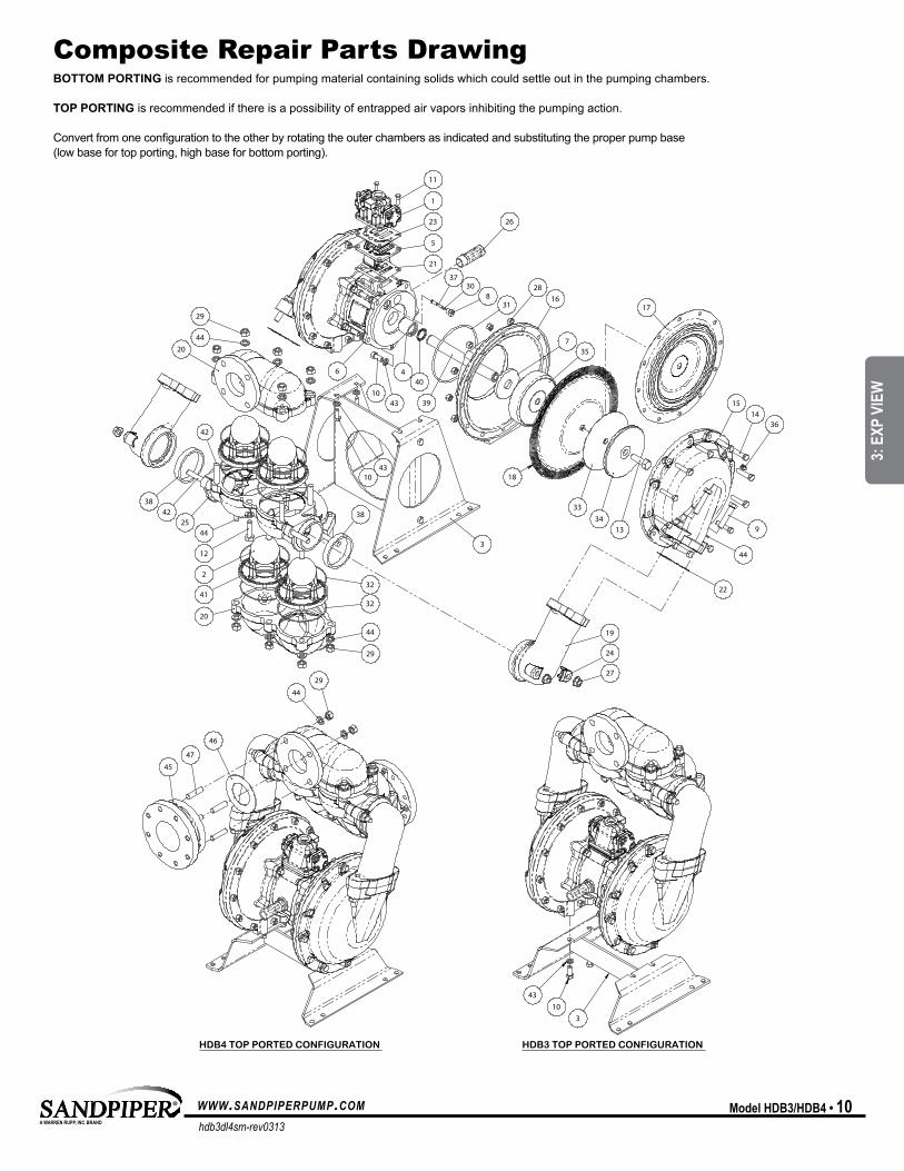
BOTTOM PORTING is recommended for pumping material containing solids which could settle out in the pumping chambers. TOP PORTING is recommended if there is a possibility of entrapped air vapors inhibiting the pumping action.
Convert from one configuration to the other by rotating the outer chambers as indicated and substituting the proper pump base (low base for top porting, high base for bottom porting).
Troubleshooting Guide Composite repair Parts drawing
15
16
14
22
3
19
27
24
29
11
1
23
5
21
6
26
9
44
25
38
41
2
44
12
37
830 28
735
18
3334
13
31
1043
440
4310
42
4236
39
44
29
32
32
44
20
20
38
17
45
47
46
44
29
4310
3
HDB3 TOP PORTED CONFIGURATION HDB4 TOP PORTED CONFIGURATION
MODEL SPECIFIC
3: E
XP V
IEW
hdb3dl4sm-rev0313
www.sandpiperpump.com11 • Model HdB3/HdB4
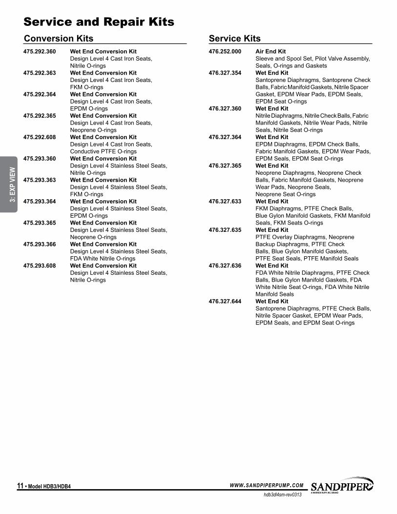
475.292.360 Wet End Conversion Kit Design Level 4 Cast Iron Seats, Nitrile O-rings475.292.363 Wet End Conversion Kit Design Level 4 Cast Iron Seats, FKM O-rings475.292.364 Wet End Conversion Kit Design Level 4 Cast Iron Seats, EPDM O-rings475.292.365 Wet End Conversion Kit Design Level 4 Cast Iron Seats, Neoprene O-rings475.292.608 Wet End Conversion Kit Design Level 4 Cast Iron Seats, Conductive PTFE O-rings475.293.360 Wet End Conversion Kit Design Level 4 Stainless Steel Seats, Nitrile O-rings475.293.363 Wet End Conversion Kit Design Level 4 Stainless Steel Seats, FKM O-rings475.293.364 Wet End Conversion Kit Design Level 4 Stainless Steel Seats, EPDM O-rings475.293.365 Wet End Conversion Kit Design Level 4 Stainless Steel Seats, Neoprene O-rings475.293.366 Wet End Conversion Kit Design Level 4 Stainless Steel Seats, FDA White Nitrile O-rings475.293.608 Wet End Conversion Kit Design Level 4 Stainless Steel Seats, Nitrile O-rings
476.252.000 Air End Kit Sleeve and Spool Set, Pilot Valve Assembly, Seals, O-rings and Gaskets476.327.354 Wet End Kit Santoprene Diaphragms, Santoprene Check Balls, Fabric Manifold Gaskets, Nitrile Spacer Gasket, EPDM Wear Pads, EPDM Seals, EPDM Seat O-rings476.327.360 Wet End Kit Nitrile Diaphragms, Nitrile Check Balls, Fabric Manifold Gaskets, Nitrile Wear Pads, Nitrile Seals, Nitrile Seat O-rings476.327.364 Wet End Kit EPDM Diaphragms, EPDM Check Balls, Fabric Manifold Gaskets, EPDM Wear Pads, EPDM Seals, EPDM Seat O-rings476.327.365 Wet End Kit Neoprene Diaphragms, Neoprene Check Balls, Fabric Manifold Gaskets, Neoprene Wear Pads, Neoprene Seals, Neoprene Seat O-rings476.327.633 Wet End Kit FKM Diaphragms, PTFE Check Balls, Blue Gylon Manifold Gaskets, FKM Manifold Seals, FKM Seats O-rings476.327.635 Wet End Kit PTFE Overlay Diaphragms, Neoprene Backup Diaphragms, PTFE Check Balls, Blue Gylon Manifold Gaskets, PTFE Seat Seals, PTFE Manifold Seals476.327.636 Wet End Kit FDA White Nitrile Diaphragms, PTFE Check Balls, Blue Gylon Manifold Gaskets, FDA White Nitrile Seat O-rings, FDA White Nitrile Manifold Seals476.327.644 Wet End Kit Santoprene Diaphragms, PTFE Check Balls, Nitrile Spacer Gasket, EPDM Wear Pads, EPDM Seals, and EPDM Seat O-rings
Service and repair KitsConversion Kits Service Kits
3: E
XP V
IEW
hdb3dl4sm-rev0313
www.sandpiperpump.com Model HdB3/HdB4 • 12
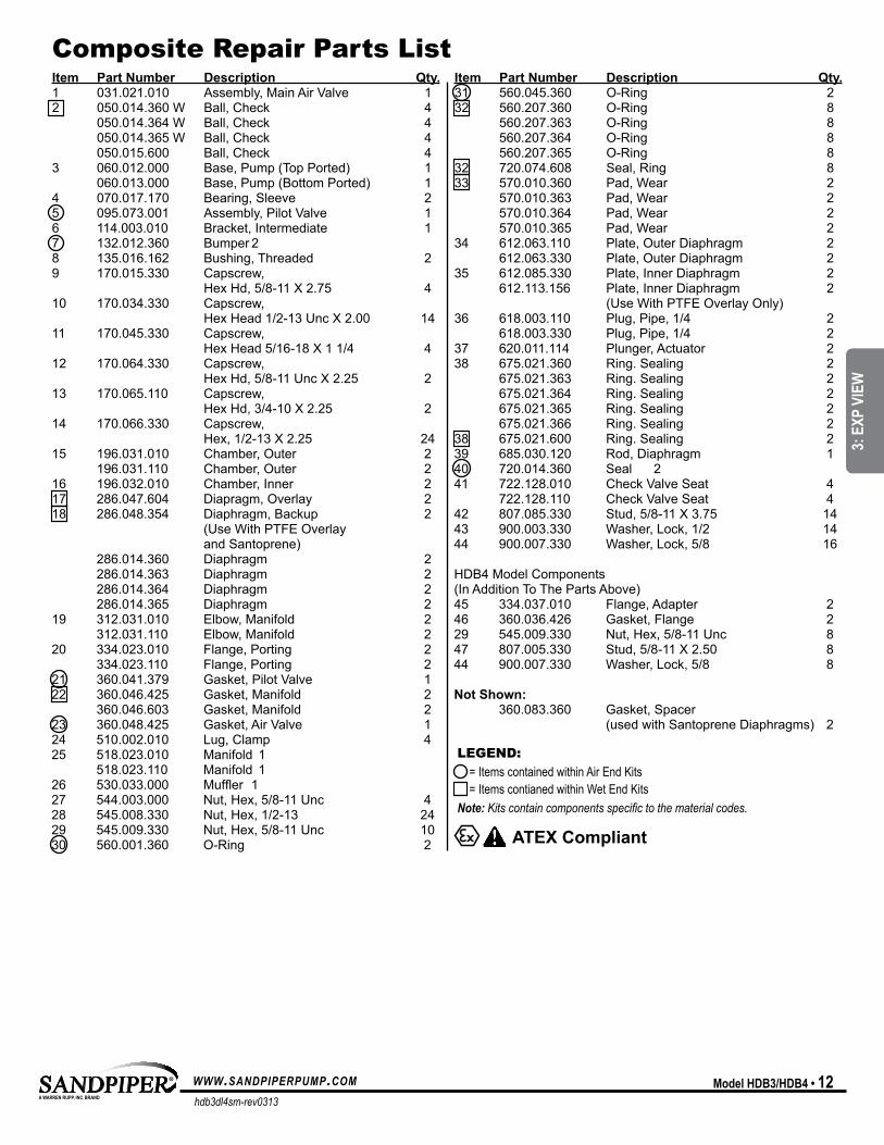
Service and repair Kits Composite repair Parts listItem Part Number Description Qty.1 031.021.010 Assembly, Main Air Valve 12 050.014.360 W Ball, Check 4 050.014.364 W Ball, Check 4 050.014.365 W Ball, Check 4 050.015.600 Ball, Check 43 060.012.000 Base, Pump (Top Ported) 1 060.013.000 Base, Pump (Bottom Ported) 14 070.017.170 Bearing, Sleeve 25 095.073.001 Assembly, Pilot Valve 16 114.003.010 Bracket, Intermediate 17 132.012.360 Bumper 28 135.016.162 Bushing, Threaded 29 170.015.330 Capscrew, Hex Hd, 5/8-11 X 2.75 410 170.034.330 Capscrew, Hex Head 1/2-13 Unc X 2.00 1411 170.045.330 Capscrew, Hex Head 5/16-18 X 1 1/4 412 170.064.330 Capscrew, Hex Hd, 5/8-11 Unc X 2.25 213 170.065.110 Capscrew, Hex Hd, 3/4-10 X 2.25 214 170.066.330 Capscrew, Hex, 1/2-13 X 2.25 2415 196.031.010 Chamber, Outer 2 196.031.110 Chamber, Outer 216 196.032.010 Chamber, Inner 217 286.047.604 Diapragm, Overlay 218 286.048.354 Diaphragm, Backup 2 (Use With PTFE Overlay and Santoprene) 286.014.360 Diaphragm 2 286.014.363 Diaphragm 2 286.014.364 Diaphragm 2 286.014.365 Diaphragm 219 312.031.010 Elbow, Manifold 2 312.031.110 Elbow, Manifold 220 334.023.010 Flange, Porting 2 334.023.110 Flange, Porting 221 360.041.379 Gasket, Pilot Valve 122 360.046.425 Gasket, Manifold 2 360.046.603 Gasket, Manifold 223 360.048.425 Gasket, Air Valve 124 510.002.010 Lug, Clamp 425 518.023.010 Manifold 1 518.023.110 Manifold 126 530.033.000 Muffler 127 544.003.000 Nut, Hex, 5/8-11 Unc 428 545.008.330 Nut, Hex, 1/2-13 2429 545.009.330 Nut, Hex, 5/8-11 Unc 1030 560.001.360 O-Ring 2
Item Part Number Description Qty.31 560.045.360 O-Ring 232 560.207.360 O-Ring 8 560.207.363 O-Ring 8 560.207.364 O-Ring 8 560.207.365 O-Ring 832 720.074.608 Seal, Ring 833 570.010.360 Pad, Wear 2 570.010.363 Pad, Wear 2 570.010.364 Pad, Wear 2 570.010.365 Pad, Wear 234 612.063.110 Plate, Outer Diaphragm 2 612.063.330 Plate, Outer Diaphragm 235 612.085.330 Plate, Inner Diaphragm 2 612.113.156 Plate, Inner Diaphragm 2 (Use With PTFE Overlay Only) 36 618.003.110 Plug, Pipe, 1/4 2 618.003.330 Plug, Pipe, 1/4 237 620.011.114 Plunger, Actuator 238 675.021.360 Ring. Sealing 2 675.021.363 Ring. Sealing 2 675.021.364 Ring. Sealing 2 675.021.365 Ring. Sealing 2 675.021.366 Ring. Sealing 238 675.021.600 Ring. Sealing 239 685.030.120 Rod, Diaphragm 140 720.014.360 Seal 241 722.128.010 Check Valve Seat 4 722.128.110 Check Valve Seat 442 807.085.330 Stud, 5/8-11 X 3.75 1443 900.003.330 Washer, Lock, 1/2 1444 900.007.330 Washer, Lock, 5/8 16 HDB4 Model Components (In Addition To The Parts Above) 45 334.037.010 Flange, Adapter 246 360.036.426 Gasket, Flange 229 545.009.330 Nut, Hex, 5/8-11 Unc 847 807.005.330 Stud, 5/8-11 X 2.50 844 900.007.330 Washer, Lock, 5/8 8
Not Shown: 360.083.360 Gasket, Spacer (used with Santoprene Diaphragms) 2
ATEX Compliant
lEGENd:=ItemscontainedwithinAirEndKits=ItemscontianedwithinWetEndKitsNote: Kits contain components specific to the material codes.
MODEL SPECIFIC
3: E
XP V
IEW
hdb3dl4sm-rev0313
www.sandpiperpump.com13 • Model HdB3/HdB4
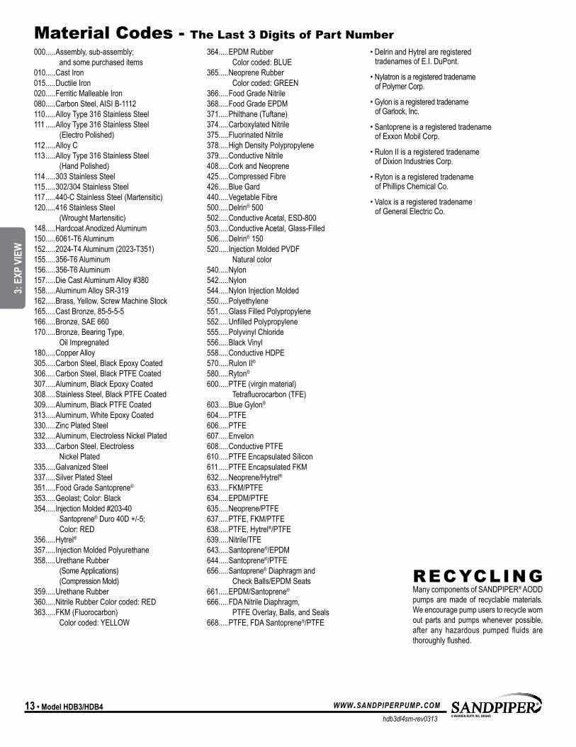
material Codes - The last 3 digits of Part Number000.....Assembly,sub-assembly;
and some purchased items010.....CastIron015.....DuctileIron020.....FerriticMalleableIron080.....CarbonSteel,AISIB-1112110 .....AlloyType316StainlessSteel111 .....AlloyType316StainlessSteel
(ElectroPolished)112 .....AlloyC113 .....AlloyType316StainlessSteel
(HandPolished)114 .....303StainlessSteel115 .....302/304StainlessSteel117 .....440-CStainlessSteel(Martensitic)120.....416StainlessSteel
(WroughtMartensitic)148.....HardcoatAnodizedAluminum150.....6061-T6Aluminum152.....2024-T4Aluminum(2023-T351)155.....356-T6Aluminum156.....356-T6Aluminum157.....DieCastAluminumAlloy#380158.....AluminumAlloySR-319162.....Brass,Yellow,ScrewMachineStock165.....CastBronze,85-5-5-5166.....Bronze,SAE660170.....Bronze,BearingType,
OilImpregnated180.....CopperAlloy305.....CarbonSteel,BlackEpoxyCoated306.....CarbonSteel,BlackPTFECoated307.....Aluminum,BlackEpoxyCoated308.....StainlessSteel,BlackPTFECoated309.....Aluminum,BlackPTFECoated313.....Aluminum,WhiteEpoxyCoated330.....ZincPlatedSteel332.....Aluminum,ElectrolessNickelPlated333.....CarbonSteel,Electroless
NickelPlated335.....GalvanizedSteel337.....SilverPlatedSteel351.....FoodGradeSantoprene®
353.....Geolast;Color:Black354.....InjectionMolded#203-40
Santoprene®Duro40D+/-5; Color:RED
356.....Hytrel®357.....InjectionMoldedPolyurethane358.....UrethaneRubber
(SomeApplications) (CompressionMold)
359.....UrethaneRubber360.....NitrileRubberColorcoded:RED363.....FKM(Fluorocarbon)
Colorcoded:YELLOW
364.....EPDMRubber Colorcoded:BLUE
365.....NeopreneRubber Colorcoded:GREEN
366.....FoodGradeNitrile368.....FoodGradeEPDM371.....Philthane(Tuftane)374.....CarboxylatedNitrile375.....FluorinatedNitrile378.....HighDensityPolypropylene379.....ConductiveNitrile408.....CorkandNeoprene425.....CompressedFibre426.....Blue Gard440.....VegetableFibre500.....Delrin®500502.....ConductiveAcetal,ESD-800503.....ConductiveAcetal,Glass-Filled506.....Delrin®150520.....InjectionMoldedPVDF
Naturalcolor540.....Nylon542.....Nylon544.....NylonInjectionMolded550.....Polyethylene551.....GlassFilledPolypropylene552.....UnfilledPolypropylene555.....PolyvinylChloride556.....BlackVinyl558.....ConductiveHDPE570.....RulonII®580.....Ryton®
600.....PTFE(virginmaterial) Tetrafluorocarbon(TFE)
603.....Blue Gylon®
604.....PTFE606.....PTFE607.....Envelon608.....ConductivePTFE610.....PTFEEncapsulatedSilicon611 .....PTFEEncapsulatedFKM632.....Neoprene/Hytrel®633.....FKM/PTFE634.....EPDM/PTFE635.....Neoprene/PTFE637.....PTFE,FKM/PTFE638.....PTFE,Hytrel®/PTFE639.....Nitrile/TFE643.....Santoprene®/EPDM644.....Santoprene®/PTFE656 .....Santoprene®Diaphragmand
CheckBalls/EPDMSeats661.....EPDM/Santoprene®
666.....FDANitrileDiaphragm, PTFEOverlay,Balls,andSeals
668.....PTFE,FDASantoprene®/PTFE
•DelrinandHytrelareregistered tradenamesofE.I.DuPont.
•Nylatronisaregisteredtradename ofPolymerCorp.
•Gylon is a registered tradename ofGarlock,Inc.
•Santoprene is a registered tradename ofExxonMobilCorp.
•RulonIIisaregisteredtradename ofDixionIndustriesCorp.
•Ryton is a registered tradename ofPhillipsChemicalCo.
•Valoxisaregisteredtradename ofGeneralElectricCo.
rECyClING ManycomponentsofSANDPIPER®AODDpumps are made of recyclable materials. Weencouragepumpuserstorecyclewornout parts andpumpswhenever possible,after any hazardous pumped fluids are thoroughlyflushed.
UNIVERSAL ALL SP
3: E
XP V
IEW
hdb3dl4sm-rev0313
www.sandpiperpump.com Model HdB3/HdB4 • 14
air distribution Valve assembly
MAIN AIR VALVE ASSEMBLy PARTS LISTitem part number description Qty1 031.021.010 AirValveAssembly 1 1-A 095.043.010 Body,AirValve 1 1-B 031.018.000 SleeveandSpoolSet 11-C 132.014.358 Bumper 21-D 560.020.360 O-Ring 61-E 360.010.425 Gasket 21-F 165.011.010 EndCap 21-G 170.032.330 HexHeadCapscrew 8
IMPORTANTRead these instructions completely, before installation and start-up. It is the responsibility of the purchaser to retain this manual for reference. Failure to comply with the recommendations stated in this manual will damage the pump, and void factory warranty.
1-A
1-B1-B
1-C1-E
1-F
1-G
1-C
1-E
1-F
1-G
1-D
Air Distribution Valve ServicingSeerepairpartsdrawing,removescrews.Step 1:RemoveHexHeadCapScrews(1-G).Step 2: Removeendcap(1-F),gasket(1-E)andbumper(1-C).Step 3: Removespoolpartof(1-B)(caution:donotscratch).Step 4: Presssleeve(1-B)frombody(1-A).Step 5:InspectO-Ring(1-D)andreplaceifnecessary.Step 6:LightlylubricateO-Rings(1-D)onsleeve(1-B).Step 7: Presssleeve(1-B)intobody(1-A).Step 8: Reassembleinreverseorder,startingwithstep3.
note: Sleeveandspool(1-B)setismatchgroundtoaspecifiedclearancesleeveandspools(1-B)cannotbeinterchanged.
MODEL SPECIFIC
4: A
IR E
ND
hdb3dl4sm-rev0313
www.sandpiperpump.com15 • Model HdB3/HdB4
Pilot Valve assembly
PILOT VALVE ASSEMBLy PARTS LIST
item part number description Qty5 095.073.001 PilotValveAssembly 15-A 095.070.558 ValveBody 15-B 755.025.000 Sleeve(WithO-Rings) 15-C 560.033.360 O-Ring(Sleeve) 45-D 775.026.000 Spool(WithO-Rings) 15-E 560.023.360 O-Ring(Spool) 25-F 675.037.080 RetainingRing 1
5-A
5-F
5-D
5-B
5-C
5-E
Pilot Valve ServicingWithPilotValveremovedfrompump.Step 1:Removesnapring(5F).Step 2:Removesleeve(5B),inspectO-Rings(5C), replace if required.Step 3: Removespool(5D)fromsleeve(5B), inspectO-Rings(5E),replaceifrequired.Step 4: LightlylubricateO-Rings(5C)and(5E). Reassemble in reverse order.
MODEL SPECIFIC
4: A
IR E
ND
hdb3dl4sm-rev0313
www.sandpiperpump.com Model HdB3/HdB4 • 16
Pilot Valve assemblyStep 1: With manifolds and outer chambersremoved, remove diaphragm assemblies from diaphragm rod. dO nOTuseapipewrenchorsimilartooltoremoveassemblyfromrod.Flawsintherodsurfacemaydamagebearingsandseal.Soft jawsin a vise are recommended to prevent diaphragm rod damage.
Step 1.A: nOTe: Notall innerdiaphragmplatesare threaded.Somemodels utilize a throughholeintheinnerdiaphragmplate.Ifrequiredtoseparatediaphragm assembly, place assembly in a vise, gripping on theexterior cast diameter of the innerplate.Turntheouterplateclockwisetoseparatetheassembly.
Always inspect diaphragms for wear cracks orchemicalattack. Inspect innerandouterplates fordeformities,rustscaleandwear.Inspectintermediatebearingsforelongationandwear.Inspectdiaphragmrodforwearormarks.Clean or repair if appropriate. Replace as required.
Step 2: Reassembly:TherearetwodifferenttypesofdiaphragmplateassembliesutilizedthroughouttheSandpiperproductline:Outerplatewithathreadedstud, diaphragm, and a threaded inner plate.
Outer platewith a threaded stud, diaphragm, andan inner platewith throughhole.Secure threadedinnerplateinavise.Ensurethattheplatesarebeinginstalledwiththeouterradiusagainstthediaphragm.
Step 3:Lightlylubricate,withacompatiblematerial,the inner faces of both outer and inner diaphragm plates whenusingonnonOverlaydiaphragms(ForEPDMwater isrecommended).No lubrication isrequired.
Step 4: Push the threaded outer diaphragmplate through the center hole of the diaphragm. note: Most diaphragms are installed with thenatural bulge out towards the fluid side. S05,S07, and S10 non–metallic units are installedwith the natural bulge in towards the air side.
Step 5: Thread or place, outer plate stud into the inner plate. For threaded inner plates, use atorquewrench to tighten the assembly together.Torquevaluesarecalledoutontheexplodedview.
Repeat procedure for second side assembly. Allow aminimum of 15minutes to elapse aftertorquing,thenre-torquetheassemblytocompensatefor stress relaxation in the clamped assembly.
Step 6: Thread one assembly onto the diaphragm rodwithsealingwasher (whenused)andbumper.
Step 7: Instal l diaphragm rod assemblyinto pump and secure by installing the outer chamber in place and tightening the capscrews.
Step 8: On opposite side of pump, thread the remainingassemblyontothediaphragmrod.Usingatorquewrench,tightentheassemblytothediaphragmrod.Aligndiaphragmthroughboltholes,alwaysgoingforwardpasttherecommendedtorque.Torquevaluesarecalledoutontheexplodedview.neVer reverse to align holes, if alignment cannot be achieved without damage to diaphragm, loosen completeassemblies, rotate diaphragm and reassemble as described above.
Step 9: Complete assembly of entire unit.One PieceDiaphragmServicing (Bonded PTFEwith integral plate)TheOnePiecediaphragmhasa threaded stud installed in the integral plate at the factory. The inner diaphragm plate has a through hole instead of a threaded hole. Place the innerplateover thediaphragmstudand thread the firstdiaphragm/innerplateontothediaphragmrodonlyuntiltheinnerplatecontactstherod.Donottighten.Asmallamountofgreasemaybeappliedbetweentheinner plate and the diaphragm to facilitate assembly. Insertthediaphragm/rodassemblyintothepumpand install the outer chamber. Turn the pump over andthreadtheseconddiaphragm/innerplateontothe diaphragm rod. Turn the diaphragm until the inner plate contacts the rod and hand tighten the assembly. Continue tightening until the bolt holes alignwiththeinnerchamberholes.dO nOT LeAVe THe ASSeMBLY LOOSe.
diaphragm Servicing
IMPORTANTRead these instructions completely, before installation and start-up. It is the responsibility of the purchaser to retain this manual for reference. Failure to comply with the recommendations stated in this manual will damage the pump, and void factory warranty.
UNIVERSAL ALL SP
5: W
ET E
ND
Declaration of Conformity
Signature of authorized person Date of issue
Printed name of authorized person
Revision Level: F
TitleDavid Roseberry Engineering Manager
October 20, 2005
Date of revisionAugust 23, 2012
Manufacturer: Warren Rupp, Inc.®, 800 N. Main Street, P.O. Box 1568,Mansfield, Ohio, 44901-1568 USA
Certifies that Air-Operated Double Diaphragm Pump Series: HDB, HDF, M Non-Metallic, S Non-Metallic, M Metallic, S Metallic, T Series, G Series, U Series, EH and SH High Pressure,
RS Series, W Series, SMA and SPA Submersibles, and Tranquilizer Surge Suppressors comply with the European Community Directive 2006/42/EC on Machinery, according to Annex VIII.
This product has used Harmonized Standard EN809:1998+A1:2009, Pumps and Pump Units for Liquids - Common Safety Requirements, to verify conformance.
written warranty5 - yEar limited Product warranty
Quality System ISO9001 Certified • Environmental Management Systems ISO14001 Certified
Warren Rupp, Inc. (“Warren Rupp”) warrants to the original end-use purchaser that no product sold byWarren Rupp that bears a Warren Rupp brand shall fail under normal use and service due to a defect in material
or workmanship within five years from the date of shipment from Warren Rupp’s factory. Warren Rupp brandsinclude SANDPIPER®, MARATHON®, PortaPump®, SludgeMaster™ and Tranquilizer®.
~ See complete warranty at www. sandpiperpump.com/About/guaranteesandwarranties.html ~
UNIVERSAL ALL SP
7: W
ARRA
NTY

EC Declaration of ConformityIn accordance with ATEX Directive 94/9/EC,
Equipment intended for use in potentially explosive environments.
Applicable Standard:EN13463-1: 2001,EN13463-5: 2003
David Roseberry, Engineering ManagerDATE/APPROVAL/TITLE:27 MAY 2010
EN 60079-25: 2004For pumps equipped with Pulse Output ATEX OptionKEMA Quality B.V. (0344)
AODD Pumps and Surge SuppressorsFor Type Examination Designations
AODD (Air-Operated Double Diaphragm) PumpsEC Type Examination Certificate No. Pumps: KEMA 09ATEX0071 XKEMA Quality B.V.Utrechtseweg 3106812 AR Arnhem, The Netherlands
Manufacturer: Warren Rupp, Inc.®, A Unit of IDEX Corportion800 North Main Street, P.O. Box 1568, Mansfield, OH 44901-1568 USA
EC Declaration of ConformityATEX Summary of Markings
Type Marking Listed In Non-Conductive Fluids
EC Type Certificate No. Pumps: KEMA 09ATEX0071 X Type Certificate No. Pumps: KEMA 09ATEX0072 X Type Certificate No. Suppressors: KEMA 09ATEX0073
Pump types, S1F, S15, S20, and S30 provided with the pulse output option
II 2 G Ex ia c IIC T5II 3/2 G Ex ia c IIC T5II 2 D Ex c iaD 20 IP67 T100oC
KEMA 09ATEX0071 XKEMA 09ATEX0071 XKEMA 09ATEX0071 X
NoYesYes
KEMA 09ATEX0071 XCE 0344
Surge Suppressors all types II 2 G T5II 3/2 G T5II 2 D T100oC
KEMA 09ATEX0073KEMA 09ATEX0073KEMA 09ATEX0073
NoYesYes
KEMA 09ATEX0073CE
Pump types, S1F, S15, S20, and S30 provided with the integral solenoid option
II 2 G EEx m c II T5II 3/2 G EEx m c II T5II 2 D c IP65 T100oC
KEMA 09ATEX0071 XKEMA 09ATEX0071 XKEMA 09ATEX0071 X
NoYesYes
KEMA 09ATEX0071 XCE 0344
Pump types, HDB1½, HDB40, HDB2, HDB50, HDB3, HDF1, HDF25, HDF2, HDF3M, PB¼, S05, S1F, S15, S20, S30, SB1, SB25, ST1½, ST40, G15, G20, and G30, without the above listed options, no aluminum parts
II 1 G c T5II 3/1 G c T5II 1 D c T100oCI M1 cI M2 c
KEMA 09ATEX0071 XKEMA 09ATEX0071 XKEMA 09ATEX0071 XKEMA 09ATEX0071 XKEMA 09ATEX0072 X
NoYesYesNoYes
KEMA 09ATEX0071 XKEMA 09ATEX0072 XCE 0344
Pump types, DMF2, DMF3, HDB1½, HDB40, HDB2, HDB50, HDB3, HDF1, HDF25, HDF2, HDF3M, PB¼, S05, S1F, S15, S20, S30, SB1, SB25, SE½, ST1, ST25, ST1½, ST40, U1F, G05, G1F, G15, G20, and G30
II 2 G c T5II 3/2 G c T5II 2 D c T100oC
KEMA 09ATEX0072 XKEMA 09ATEX0072 XKEMA 09ATEX0072 X
NoYesYes
KEMA 09ATEX0072 XCE
EC Declaration of Conformity In accordance with ATEX Directive 94/9/EC, Equipment intended for use in potentially explosive environments.
Applicable Standard:EN13463-1: 2001,EN13463-5: 2003
David Roseberry, Engineering ManagerDATE/APPROVAL/TITLE:27 MAY 2010
EN 60079-25: 2004For pumps equipped with Pulse Output ATEX OptionKEMA Quality B.V. (0344)
AODD Pumps and Surge SuppressorsFor Type Examination Designations, see page 2 (back)
AODD (Air-Operated Double Diaphragm) PumpsEC Type Examination Certificate No. Pumps: KEMA 09ATEX0071 XKEMA Quality B.V.Utrechtseweg 3106812 AR Arnhem, The Netherlands
Manufacturer: Warren Rupp, Inc.®, A Unit of IDEX Corportion800 North Main Street, P.O. Box 1568, Mansfield, OH 44901-1568 USA
UNIVERSAL ALL SP