Embed Size (px)
Citation preview

SA
FE
TY
•
QU
AL
ITY
•
TE
CH
NO
LO
GY
Certification of ConstructionTechnical Guide 2014
Moodle
CoPY

Moodle
CoPY
3. ESSENTIAL REQUIREMENTS AND GUIDANCE
3
Moodle
CoPY
Electrical Installers Guide to Certificationand the Scottish Building Standards
Technical Guidance for Certifiers of Construction(Electrical Installations to BS 7671)
SELECT believe that the guidance and information contained in this guide is correct, but all parties must rely on their own skill and judgement when making use of it.
SELECT assume no liability for any loss or damage caused by error or omission, whether as the result of negligence or any other cause. Any such liability is disclaimed.
This guide may also be amended by SELECT and re-issued, due to amendments to the Scottish Building Standards or in the light of experience of its use.
All rights reserved. No part of this publication may be reproduced without the prior permission of SELECT.
Copyright © SELECT 2005
July 2014

3. ESSENTIAL REQUIREMENTS AND GUIDANCE
4
Moodle
CoPY
Technical Guide 2014Contents
Preface 6
Introduction 7
1. Building Legislation
1.1 Regulation 8 - Building Durability, Workmanship and Fitness of Materials 8
1.2 Regulation 9 - Building Standards Applicable to Construction 8-9
1.3 Regulation 10 - Building Standards Applicable to Demolition 10
1.4 Regulation 11 - Building Standards Applicable to the Provision of Services, Fittings and Equipment 10
1.5 Regulation 12 - Building Standards Applicable to Conversions 10-11
2. Requirements for Building Warrants
2.1 Building Warrant Requirements for Electrical Work in New Buildings 12-13
2.2 Building Warrant Requirements for Electrical Work in Existing Buildings 13-15
2.3 Buildings and Work not Subject to Building Regulations 13
3. Basic Requirements for Construction Works and Associated Guidance
3.1 Structure (Mechanical Resistance and Stability)
3.1.1 Notches, holes and chases 16-18
3.2 Fire (Safety in Case of Fire)
3.2.1 Openings and service penetrations (fire stopping) 19-21
3.2.2 Thermoplastic materials in light fittings 21
3.2.3 Escape routes (obstructions) 22-23
3.2.4 Escape lighting 23-24
3.2.5 Fire detection and fire alarm systems (communication of fire) 25-34
Pages(s)

3. ESSENTIAL REQUIREMENTS AND GUIDANCE
5
Moodle
CoPY
3.3 Environment (Hygiene, Health and the Enviroment)
3.3.1 Service penetrations to external walls 35
3.3.2 Facilities in dwellings 35
3.3.3 Sanitary facilities 35
3.3.4 Heating of dwellings 35
3.3.5 Ventilation 36-37
3.3.6 Carbon monoxide detection 37-39
3.4 Safety (Safety and Accessibility in Use)
3.4.1 Access to and within buildings 40-41
3.4.2 Electrical safety 41-44
3.4.3 Aids to communication 45
3.4.4 Danger from accidents 45
3.5 Noise (Protection Against Noise)
3.5.1 Resistance to the passage of sound 46-47
3.6 Energy (Energy Economy and Heat Retention)
3.6.1 Heating and hot water systems 48-59
3.6.2 Artificial and display lighting 60-63
3.7 Sustainability (Sustainable Use of Natural Resources)
3.7.1 Statement of sustainability 64-68
4. Certification
4.1 Certification Practice 69
4.2 Completion of the Scheme Checklist 69-72
4.3 Completion of the Certificate of Construction (Electrical Installations to BS 7671) 73-74
4.4 Completion of Appropriate British Standard Certification 75
4.5 Certification of Work Not Carried Out by the Approved Body 75
Examples of Completed British Standard Certification 76-78
Appendix A - Sources of information 79
Appendix B - Explanation of 0numbered terms based on SBS definitions 80-82
3. ESSENTIAL REQUIREMENTS AND GUIDANCE
6
Preface
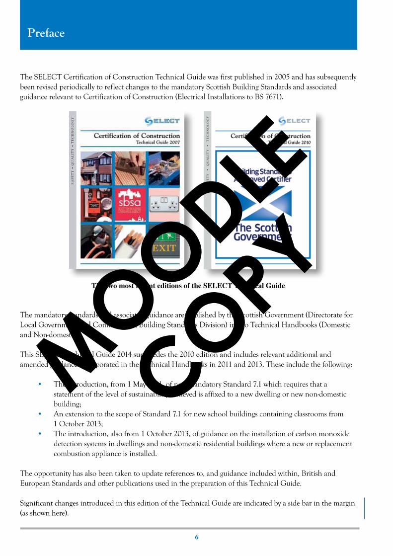
The SELECT Certification of Construction Technical Guide was first published in 2005 and has subsequently been revised periodically to reflect changes to the mandatory Scottish Building Standards and associated guidance relevant to Certification of Construction (Electrical Installations to BS 7671).
The mandatory standards and associated guidance are published by the Scottish Government (Directorate for Local Government and Communities, Building Standards Division) in two Technical Handbooks (Domestic and Non-domestic).
This SELECT Technical Guide 2014 supersedes the 2010 edition and includes relevant additional and amended guidance incorporated in the Technical Handbooks in 2011 and 2013. These include the following:
• The introduction, from 1 May 2011, of new mandatory Standard 7.1 which requires that a statement of the level of sustainability achieved is affixed to a new dwelling or new non-domestic building;
• An extension to the scope of Standard 7.1 for new school buildings containing classrooms from 1 October 2013; • The introduction, also from 1 October 2013, of guidance on the installation of carbon monoxide
detection systems in dwellings and non-domestic residential buildings where a new or replacement combustion appliance is installed.
The opportunity has also been taken to update references to, and guidance included within, British and European Standards and other publications used in the preparation of this Technical Guide.
Significant changes introduced in this edition of the Technical Guide are indicated by a side bar in the margin (as shown here).
The two most recent editions of the SELECT Technical Guide
Moodle
CoPY

3. ESSENTIAL REQUIREMENTS AND GUIDANCE
7
Moodle
CoPY
Introduction
The main purpose of this Technical Guide is to provide technical guidance for electrical installers who, in accordance with the Building (Scotland) Act 2003, are registered in a Scheme for Certification of Construction (Electrical Installations to BS 7671).
These installers, known as Approved Bodies, have a statutory duty to carry out the construction of electrical installations in accordance with the Standards required by the Building (Scotland) Regulations 2004.
Each Approved Body has at least one registered Approved Certifier of Construction (Electrical Installations), who is required to ensure that work carried out should meet the relevant parts of the above requirements before signing and submitting each Certificate of Construction.
Guidance on how to achieve the Standards set in the Building (Scotland) Regulations 2004 is given in the two Scottish Building Standards (SBS) Technical Handbooks (Domestic and Non-domestic). The arrangement of Sections 1 -7 within each handbook relate directly to the basic requirements for construction works of the Construction Products Regulation (as published by the European Commission) as follows:
Section 1 – Structure (Mechanical resistance and stability)Section 2 – Fire (Safety in case of fire)Section 3 – Environment (Hygiene, health and the environment)Section 4 – Safety (Safety and accessibility in use)Section 5 – Noise (Protection against noise)Section 6 – Energy (Energy economy and heat retention)Section 7 –Sustainability (Sustainable use of natural resources)
Each of the seven Sections consists of an introduction and guidance on the individual Standards within each Section. Where any building contains both domestic and non-domestic use, it is a general principle that the more stringent of the two sets of recommendations should be used.
The requirements for electrical safety are given in Standards 4.5 and 4.6 of Section 4 in each Technical Handbook. There are however a number of other Standards within the above Sections that are of particular relevance to electrical installations, and this guide provides details of these together with appropriate methods of compliance.
This guide applies to any electrical installation within the scope of the Building (Scotland) Regulations, including work for which a warrant is not required (see Chapter 2 of this guide).
It should be noted that the normal method of compliance with the Building Regulations is to follow the recommendations in the SBS Technical Handbooks. The guidance in these handbooks is not however mandatory and compliance with the Regulations can be achieved by other methods. These Handbooks are available to view and download on the Scottish Building Standards Division (BSD) website (www.scotland.gov.uk/bsd).
3. ESSENTIAL REQUIREMENTS AND GUIDANCE
8
Moodle
CoPY
1. Building Legislation
The following Building Regulations require to be observed during the construction of electrical installations within the scope of these Regulations.
Note - The 0numbered terms in this guide are explained in Appendix B.
1.1 Regulation 8 Durability, Workmanship and Fitness of Materials
Materials, fittings and components used in the construction of a building must be suitable for their purpose, correctly used or applied and sufficiently durable taking account of normal maintenance practices. Construction products on the EU market covered by a harmonised European product standard should normally have CE marking. Electrical installation work carried out in accordance with BS 7671 (IET Wiring Regulations), in particular the requirements for Selection and Erection of Equipment, will satisfy the requirements of Regulation 8.
1.2 Regulation 9 Building Standards Applicable to Construction
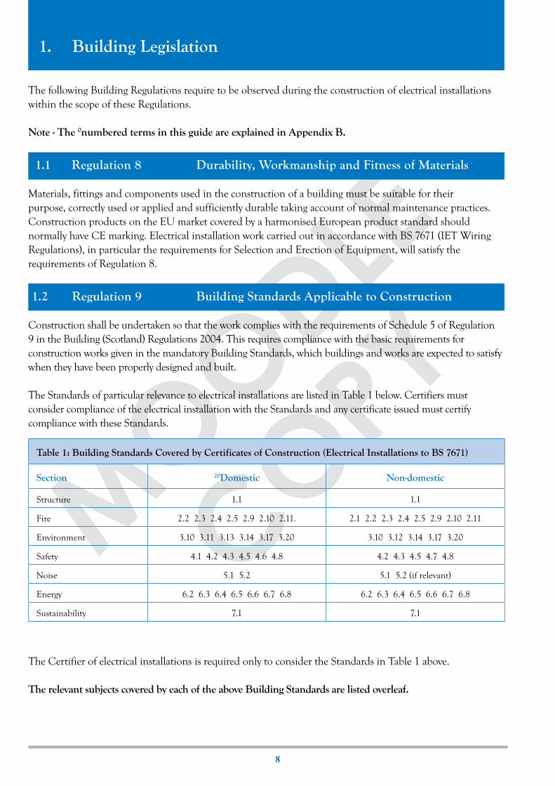
Construction shall be undertaken so that the work complies with the requirements of Schedule 5 of Regulation 9 in the Building (Scotland) Regulations 2004. This requires compliance with the basic requirements for construction works given in the mandatory Building Standards, which buildings and works are expected to satisfy when they have been properly designed and built.
The Standards of particular relevance to electrical installations are listed in Table 1 below. Certifiers must consider compliance of the electrical installation with the Standards and any certificate issued must certify compliance with these Standards.
The Certifier of electrical installations is required only to consider the Standards in Table 1 above.
The relevant subjects covered by each of the above Building Standards are listed overleaf.
Table 1: Building Standards Covered by Certificates of Construction (Electrical Installations to BS 7671)
Section 20Domestic Non-domestic
Structure 1.1 1.1
Fire 2.2 2.3 2.4 2.5 2.9 2.10 2.11. 2.1 2.2 2.3 2.4 2.5 2.9 2.10 2.11
Environment 3.10 3.11 3.13 3.14 3.17 3.20 3.10 3.12 3.14 3.17 3.20
Safety 4.1 4.2 4.3 4.5 4.6 4.8 4.2 4.3 4.5 4.7 4.8
Noise 5.1 5.2 5.1 5.2 (if relevant)
Energy 6.2 6.3 6.4 6.5 6.6 6.7 6.8 6.2 6.3 6.4 6.5 6.6 6.7 6.8
Sustainability 7.1 7.1

3. ESSENTIAL REQUIREMENTS AND GUIDANCE
9
Moodle
CoPY
Structure1.1 Prevention of collapse (Notches, holes and chases)
Fire2.1 1Compartmentation (Fire stopping)2.2 2Separation (Fire stopping)2.3 Structural protection (Protecting load bearing structures)2.4 Cavities (Fire stopping)2.5 Internal linings (6Thermoplastic materials in light fittings)2.9 Means of escape (Obstruction of 9escape routes)2.10 Escape lighting (Provision)2.11 Communication of fire (Provision of fire detection and fire alarm systems)
Environment3.10 Precipitation (Sealing of openings and service penetrations)3.11 Facilities in 14dwellings (Access and activity spaces)3.12 Sanitary facilities (Accessible bathrooms and shower rooms)3.13 Heating (Provision)3.14 Ventilation (Provision)3.17 Combustion appliances (Not affected by mechanical ventilation)3.20 Combustion appliances (Provision of carbon monoxide detection)
Safety4.1 Access to buildings4.2 Access within buildings (Obstructions)4.3 Stairs and ramps (Obstructions).4.5 Electrical safety (Compliance with appropriate standards)4.6 Electrical fixtures (Provision of lighting points and socket-outlets)4.7 Aids to communication (Provision)4.8 Danger from accidents (Positioning of equipment)
Noise5.1 Transmission of noise (Maintaining noise prevention measures between attached 14dwellings and
between attached 16residential buildings)5.2 Transmission of noise (Maintaining noise prevention measures between rooms in 14dwellings and
common rooms and bedrooms in 16residential buildings)
Energy6.2 Building insulation envelope (Maintaining energy conservation measures)6.3 Heating system (Provision of energy efficient control measures)6.4 Insulation of pipes, ducts, vessels (Maintaining energy conservation measures)6.5 Artificial and display lighting (Energy efficient provision and control)6.6 Mechanical ventilation and air conditioning (Provision of energy efficient control measures)6.7 Commissioning building services (To ensure optimum efficiency)6.8 Written information (Provided to occupier of building)
Sustainability7.1 Statement of sustainability (Sustainability labelling)

3. ESSENTIAL REQUIREMENTS AND GUIDANCE
1 0
Moodle
CoPYTable 2: Changes in Occupation or Use of Buildings Which Constitute a Conversion
Changes in Occupation or Use of: Conversion
A building To create a 14dwelling or 14dwellings or a part thereof(e.g. an attic space as a room in a dwelling, or a hotel as a dwelling)
A building ancillary to a 14dwelling To increase the area of human occupation(e.g. a garage attached to a dwelling as a room)
A building Which alters the number of 14dwellings in the building(e.g. sub-division of a house into two flats)
A 20domestic building To any other type of building(e.g. a house as shared residential accommodation)
A 16residential building To any other type of building (e.g. a hotel as an office)
A 16residential building Which significantly alters the characteristics of persons or significantly increases the number of expected occupants of the building(e.g. a hotel as a residential care home)
A building So that it becomes a 16residential building (e.g. offices as a backpackers hostel)
An exempt building (in terms of Schedule 1 to Regulation 3 )
To a building which is not so exempt(e.g. a railway signal box as a house)
A building To allow public access where previously there was none(e.g. development of a retail outlet in a storage building)
A building To accommodate parts into an area of different occupation where previously it was not so occupied where previously it was not so occupied (e.g. a single shop to provide for two different occupancies)
1.3 Regulation 10 Building Standards Applicable to Demolition
Demolition works – all service connections must be properly sealed including removing or making safe the supply of electric power servicing the building under demolition, and its site.
1.4 Regulation 11 Building Standards Applicable to the Provision of Services, Fittings and Equipment
Every service, fitting or item of equipment provided so as to serve a purpose of the regulations should be designed, installed and commissioned in such a way as to fulfil those purposes. Certificates must cover electrical installations as commissioned.
1.5 Regulation 12 Building Standards Applicable to Conversions
ConversionsCertain changes in occupation or use of buildings are defined as conversions and require a building warrant to be obtained before the work begins. Schedule 2 of Regulation 4 sets out changes in occupation or use which constitute a conversion; and is summarised (with examples) in Table 2 below.

3. ESSENTIAL REQUIREMENTS AND GUIDANCE
11
Moodle
CoPY
Building standards applicable to conversionsFor work which constitutes a conversion it is recognised that it may not be reasonably practicable to fully comply with all the applicable Building Standards. Schedule 6 of Regulation 12 identifies the standards which have to be met in full and those which have to be met so far as is reasonably practicable and in no case worse than before the conversion. (Note: Standard 7.1, Sustainability, does not apply to conversions). The standards relevant to electrical installations are identified in Table 3 below.
For the above Standards, the level of compliance and decision as to what is reasonably practicable is at the discretion of the Certifier. The level of compliance may or may not be able to be determined from the building warrant. If a Certifier is asked to certify work in cases of change of use or occupation that constitutes a conversion, but for which no warrant has been obtained, they should not certify the work under the scheme.
Table 3: Conversions - Building Standards Relevant to Certification of Electrical Installations
Building Standards compliance no worse than before and as close to full requirements
as reasonably practicable
Full level of requirements for the part to be converted and to any other part of the
original building affected
Section 20Domestic Non-domestic 20Domestic Non-domestic
Structure 1.1 1.1 - -
Fire 2.2 2.4 2.2 2.4 2.3 2.5 2.9 2.10 2.11 2.1 2.3 2.5 2.9 2.10 2.11
Environment 3.10 3.10 3.11 3.13 3.14 3.17 3.20 3.12 3.14 3.17 3.20
Safety 4.1 4.2 4.3 4.8 4.2 4.3 4.8 4.5 4.6 4.5 4.7
Noise - - 5.1 5.2 5.1 5.2 (if relevant)
Energy 6.2 6.3 6.4 6.5 6.6 6.2 6.3 6.4 6.5 6.6 6.7 6.8 6.7 6.8

3. ESSENTIAL REQUIREMENTS AND GUIDANCE
1 2
Moodle
CoPY
2. Requirements for Building Warrants
Introduction
Whether or not electrical work can be certified under the scheme for Certification of Construction (Electrical Installations to BS 7671) and/or is subject to the building regulations will depend upon the type of building work carried out and the nature of the work activity.
a. Certain types of electrical work are subject to building regulations and require a building warrant. Such work can be certified under the Scheme for Certification of Construction.
b. Certain types of work are subject to building regulations but exempt from the need for a building warrant. Such work is currently outwith the scope of Certification of Construction and should not therefore be certified under the Scheme.
c. Certain buildings and work are not subject to building regulations or building warrant requirements and should not therefore be certified under the Scheme.
The information given in Sections 2.1 and 2.2 of this guide is based on Schedule 3 to Regulation 5 and indicates the building warrant requirements for electrical installation work in new and existing buildings covered by the building regulations.
Examples of buildings and services which are not subject to building regulations or building warrant requirements are given in Section 2.3 overleaf.
Note - The 0numbered terms in this guide are explained in Appendix B.
2.1 Building Warrant Requirements for Electrical Work in New Buildings
Table 4 indicates the circumstances under which a building warrant is required for electrical work in new 20domestic and non-20domestic buildings.
References to new buildings also include, for example, extensions to existing buildings and most conservatories. Schedule 3 to Regulation 5 indicates that work which increases the floor area of a building requires a building warrant to be issued.
Table 4: Building Warrant Requirements for Electrical Work in New Buildings
Type of electrical workNew 20domestic buildings
(26house, 11flat or 12maisonette)New non-20domestic buildings
subject to certain exceptions (see 2.3)
Any electrical installation (except a circuit for telecommunication, alarm purposes or for transmission of sound, vision or data which operates at 19extra-low voltage and which is not connected directly or indirectly to an electricity supply which operates at a voltage higher than the above).
Building warrant required Building warrant required

3. ESSENTIAL REQUIREMENTS AND GUIDANCE
1 3
Moodle
CoPY
In such circumstances the full level of requirements of the relevant Building Standards are applicable for the extension or conservatory and any other part of the building affected by the work, e.g. interconnected 15smoke alarms may require to be installed in parts of the existing building which form part of the 9escape route.
2.2 Building Warrant Requirements for Electrical Work in Existing Buildings
The building warrant requirements for electrical work in existing 20domestic buildings are given in Table 5 overleaf, whilst those for existing non-20domestic buildings are given in Table 6 on page 15.
The information given in Tables 5 and 6 has been produced by The Scottish Government Building Standards Division and Local Authority Building Standards Scotland (LABSS).
In the context of Tables 5 and 6, where it is indicated that a building warrant is ‘Not Required’ the work must still comply with the building regulations.
Boilers - large and smallIn the context of Tables 5 and 6, a large boiler may be considered to be a combustion appliance as follows:• A solid fuel appliance with an output rating more than 50 kW.• An oil-firing appliance with an output rating more than 45 kW.• A gas-fired appliance with a net input rating more than 70 kW.
2.3 Buildings and Work Not Subject to Building Regulations
Schedule 1 to Regulation 3 gives a description of buildings and services that are not subject to the Building Regulations. These are described under Types 1 to 21 in Schedule 1 to Regulation 3.It should be noted however that electrical installation work carried out in such buildings may be subject to other legislation such as the Electricity at Work Regulations 1989. The relevant building Types in Schedule 1 are summarised as follows:
• Types 1 to 3 – Buildings or work controlled by other legislation e.g. Manufacture and Storage of Explosives Regulations, Nuclear Installations Act, Historic Buildings.
• Type 4 – Protective works e.g. building site works etc. where the public are in close proximity but are protected.
• Types 5 and 6 – Buildings not frequented by people e.g. detached buildings housing fixed plant only requiring intermittent visits.
• Types 7 and 8 – Agricultural and related buildings e.g. commercial greenhouses, small single 10storey detached buildings used solely for this purpose.
• Types 9 to 12 – Buildings or work which is so specialised that the Building Regulations are not appropriate e.g. civil engineering work, mobile homes etc.
• Types 13 and 17 to 20 – Small single 10storey buildings which do not contain flues, fixed combustion appliances or sanitary facilities. These would include conservatories and porches not exceeding 8 m2 in area and greenhouses, car ports and covered areas not exceeding 30 m2 in area.
• Types 14 to 16 – Temporary buildings not containing sleeping accommodation, such as contractors huts.

3. ESSENTIAL REQUIREMENTS AND GUIDANCE
1 4
Moodle
CoPY
Table 5 Building Warrant Requirements for Electrical Work in Existing Domestic Buildings
Domestic Buildings Work to Existing Buildings
Work Activity Type [1] FlatHouse(up to
2 storeys)
House(3 storeys & above)
Repairs and Replacement
Re-wiring [2] 24 Required Not Required Required
Electrical fixtures, e.g. luminaires 24 Not Required Not Required Not Required
New Work
Electrical work affected by demolition or alteration of the roof, external walls or elements of structure
1 Required Required Required
Electrical work adversely affecting a separating wall, e.g. recessed sockets
1 Required Required Required
New power socket outlets 1 Required Not Required Required
Mains operated fire alarm system 1 Required Not Required Required
Electrical work to automatic opening ventilators (including auto-detection)
1 Required Not Required Required
Electrically operated locks 1 Required Not Required Required
Wiring to artificial lighting 1 Required Not Required Required
Wiring to emergency lighting 1 Required Not Required Required
Electrical work associated with sprinkler system 1 Required Not Required Required
Electrical work associated with new boiler (large) 1 Required Not Required Required
Electrical work associated with new boiler (small) 6 Not Required Not Required Not Required
Electrical work associated with new shower 11, 12 Not Required Not Required Not Required
Electrical work associated with new extract fan 13 Not Required Not Required Not Required
Extra low voltage installations 22 Not Required Not Required Not Required
Note 1 Building work type as referenced in schedule 3 as follows: Type 1 – work to or in a house Type 6 – work associated with a fixed combustion heating appliance Types 11, 12 – work associated with sanitary facilities Type 13 – work associated with the provision of an extract fan Type 22 – an electrical installation operating at ELV Type 24 – work associated with the replacement of fittings or equipmentNote 2 A building warrant is not required for rewiring where it is a repair or replacement works to a level equal to the
installation (or part thereof) being repaired or replaced.

3. ESSENTIAL REQUIREMENTS AND GUIDANCE
1 5
Moodle
CoPY
Non-Domestic Buildings Work to Existing Buildings
Work Activity
Non-residential buildings with a storey, or creating a storey, not more than 7.5 m
Other non-domestic
buildingsType [1] No public access Public access [2]
Repairs and Replacement
Re-wiring [3] 24 Not Required Required Required
New Work
Electrical work affected by demolition or alteration of the roof, external walls or elements of structure
2 Required Required Required
Electrical work adversely affecting a separating wall, e.g. recessed sockets
2 Required Required Required
Electrical work adversely affecting a loadbearing wall 2 Required Required Required
New power socket outlets 2 Not Required Required Required
Automatic fire detection system 2 Not Required Required Required
Electrical work to automatic opening ventilators 2 Not Required Required Required
Electrical work to automatic fire dampers 2 Not Required Required Required
Electrically operated locks 2 Not Required Required Required
Wiring to artificial lighting 2 Not Required Required Required
Wiring to emergency lighting 2 Not Required Required Required
Outdoor luminous tube signs [4] 2 Not Required Not Required Not Required
Electrical work associated with new boiler (large) 2 Not Required Required Required
Electrical work associated with new boiler (small) 6 Not Required Not Required Not Required
Electrical work associated with new shower 11, 12 Not Required Not Required Not Required
Electrical work associated with new extract fan 13 Not Required Not Required Not Required
Extra low voltage installations 22 Not Required Not Required Not Required
Notes:1. Building work type as referenced in schedule 3.2. Non-residential buildings to which the public does not have access may include:
• Existing offices• Existing storage buildings• Existing industrial buildings e.g. factories and workshops• Existing assembly and entertainment buildings not open to the public
e.g. some educational buildings and private member clubs.Non-residential buildings to which the public has access may include:
• Existing assembly and entertainment buildings open to the public e.g. community schools, pubs and clubs.3. A building warrant is not required for rewiring where it is a repair or replacement works to a level equal to the installation (or
part thereof) being repaired or replaced.4. Subject to the Town and Country Planning (Control of Advertisement) (Scotland) Regulations 1984.
Table 6 Building Warrant Requirements for Electrical Work in Existing Non-domestic Buildings

3. ESSENTIAL REQUIREMENTS AND GUIDANCE
1 6
Moodle
CoPY
3. Basic Requirements for Construction Works and Associated Guidance
Electrical installers should observe the following requirements and guidance when undertaking the construction of an electrical installation which is within the scope of the Scottish Building Standards. Where any doubt exists regarding any of the following requirements or guidance the certifier should seek advice from the appropriate designer (structural engineer, architect, M & E consultant etc.) employed on the project.
3.1 Structure (Mechanical Resistance and Stability)
Note - The 0numbered terms in this guide are explained in Appendix B.
3.1.1 Notches, Holes and Chases (Standard 1.1)
Drilling holes through timber or masonry, cutting chases (raggles) in masonry or penetrating any part of a structure for the installation of cables, containment systems and equipment should be carried out in a manner that does not impair structural integrity.
Points to note: • Where there is any doubt about the structural integrity of any element of structure through
which services are to pass or be accommodated the advice of a structural engineer should always be sought. This particularly applies to timber I beams.
• Existing holes and notches should only be used where appropriate. • The detailed guidance given below is based on information taken from the Scottish
Government Building Standards Division (BSD) website and is derived from a separate document entitled The Small Buildings Structural Guidance (SBSG). That document provides advice on notching and drilling of floor joists and flat roof joists etc. as follows:
Detailed Guidance on Notches, Holes and Chases
Figure 3.1a Limits of holes in timber frame walls
• Holes should be drilled at the neutral axis (centreline); • Holes should be at least 300 mm apart.
There should not be any notching of wall studs, *cripple studs or lintels.
*cripple studs are the vertical members in a timber framed partition or wall either side of an opening, such as a door or window, to provide support for a lintel

3. ESSENTIAL REQUIREMENTS AND GUIDANCE
1 7
Floor and flat roof joists Notches and holes in simply supported floor and flat roof joists of depth D should be within the
following limits: a. holes should only be drilled at the neutral axis; and b. notches and holes should be at least 100 mm apart horizontally; and c. notches may be at the top or bottom of a joist but not coinciding.
Raised tie and collared roof members
Notches and holes should not be cut in rafters, ties, collars or hangers.
Trussed rafter members
Members of trussed rafters should not be cut, trimmed, notched or otherwise altered.
Figure 3.1b Limits of holes and notches in floor and flat roof joists
Limits of Holes Limits of Notches
Moodle
CoPY

3. ESSENTIAL REQUIREMENTS AND GUIDANCE
1 8
Wall chases
Chases (raggles) should be within the following limits:
• Vertical chases should not be deeper than 1/3 of the wall thickness or, in cavity walls, 1/3 of the thickness of a leaf.
• Horizontal chases should not be deeper than 1/6 of the thickness of the wall or leaf. • Chases should not impair the stability of a wall. • Where hollow blocks are used, at least 15 mm thickness of block should be retained. • Care should be taken that chases on solid partition walls are not back to back. • See illustration below.
Chases (raggles) in the leaf of a cavity wallFigure 3.1c Limits of chases (raggles) in the leaf of a cavity wall
Moodle
CoPY

3. ESSENTIAL REQUIREMENTS AND GUIDANCE
1 9
Moodle
CoPY
3.2 Fire (Safety in Case of Fire)
Note - The 0numbered terms in this guide are explained in Appendix B.
3.2.1 Openings and Service Penetrations (Standards 2.1, 2.2, 2.3 and 2.4)
Cables, containment systems, ventilation ductwork or other items of equipment may penetrate 1compartment walls or floors (normally provided in non-20domestic buildings to prevent fire spread) or 2separating floors and walls (normally provided between 14dwellings or between a 14dwelling and another building or common 9escape route).
3Cavity barriers (provided to prevent fire spread in cavities) may also be affected. For the purposes of this guidance, a cavity includes a roof space, a service riser or any other space used to run services around the building.
The above openings and penetrations require to be protected from the effects of fire. It is also essential during a fire that the load-bearing capacity of the building will continue to function until all occupants have escaped. The fire resistance durations of any elements of the structure such as the floors and ceilings should not be reduced by openings such as for recessed luminaires.
Points to note: • Any of the openings referred to above should be 4fire-stopped to inhibit the spread of smoke or fire
and maintain the effectiveness of the elements of structure. • Flush electrical accessories (or pipes, wires or other services) should not be installed in timber frame
2separating walls. • The walls and floors between an integral or adjoining garage are also considered to be 2separating. • The number of openings should be limited to as few and as small as possible. Detailed Guidance on Openings and Service Penetrations
4Fire-stopping As stated above, openings in fire resisting walls, floors and ceilings should be fire stopped to prevent the
passage of heat, smoke and toxic gas.
Where minimal 22differential movement is anticipated, either in normal use or during fire exposure, proprietary fire stopping materials such as 5intumescent mastics may be used.
The following materials are also considered appropriate: • Cement mortar. • Gypsum based plaster. • Cement or gypsum based vermiculite/perlite mixes. • Mineral fibre. • Crushed rock and blast furnace slag. • Ceramic based products (with or without resin binders).
Where 22differential movement is anticipated, proprietary sealants or sealing systems including 5intumescent products tested for the appropriate fire resistance can be used. Materials used for fire stopping should be reinforced with, or supported by, non-combustible materials where the unsupported span is more than 100 mm and non-rigid materials are used, unless field tests show that the materials used are satisfactory.
To avoid problems however, the number of holes and their sizes should be kept to a minimum.

3. ESSENTIAL REQUIREMENTS AND GUIDANCE
2 0
Note: For wiring systems passing though walls and floors which require 4fire-stopping, Regulation 527.2.3 of BS 7671: 2008(2011) requires internal sealing of non-flame propagating conduits, trunkings
etc. where the internal cross-sectional area is greater than 710 mm2 (e.g. 50 mm x 38 mm or larger trunking). 5Intumescent pillows are normally used for this purpose.
Figure 3.2a Wiring system passing through a wall requiring fire stopping
Both images courtesy of Intumescent Systems Ltd (www.envirograf.com)
Recessed downlighters - fire safety In ceilings of timber frame buildings the ceiling lining is the sole means of preventing heat from a fire
within the building from destroying the load bearing timbers of the floor or roof above. Care should therefore be taken when installing recessed downlighters in certain ceilings, as the luminaires may provide less fire protection than the plasterboard that has been removed to install the lights.
It is therefore essential that downlighters with integral or additional fire protection are installed in ceilings of timber frame buildings, particularly in ceilings of 2separating floors or 1compartment floors. Downlighters in ceilings of intermediate floors with rooms above, such as bedrooms, should also be of that type to allow occupants time to escape in the event of a fire.
The downlighters used should have fire resistance of at least 60 minutes for 2separating or 1compartment floors and 30 minutes for intermediate floors. The downlighters should have evidence of having been tested for fire performance when incorporated in a ceiling of the type into which they are to be installed, in accordance with BS 476 Part 21: 1987 or BS EN 1365-2. See also Section 3.5 (Noise) of this guide.
Ventilation systems - fire safety The potential for ventilation systems to allow the spread of fire and smoke should be considered. A
mechanical ventilation system may contribute to the spread of fire and smoke unless it is designed to shut down automatically or operate in a fire-mode if fire is detected. Ventilation ductwork passing through a separating or compartment wall or floor, or other fire resisting construction protecting escape routes, should be provided with either:
• Fire dampers; or • Fire resisting enclosures; or • Fire resisting ductwork.
Figure 3.2b Intumescent pillow within non-flame propagating trunking
Moodle
CoPY

3. ESSENTIAL REQUIREMENTS AND GUIDANCE
2 1
Moodle
CoPY
Ventilation ductwork should be fire stopped in accordance with BS 5588: 1999 Fire precautions in the design, construction and use of buildings – Part 9: Code of practice for ventilation and air conditioning ductwork. Section 6 of that standard provides guidance on design and construction including fire resisting enclosures, fire resisting ductwork and the use and activation of fire dampers.
Note: BS 5588-9: 1999 was superseded on 31 October 2008 by BS 9999: 2008 Code of practice for fire safety in the design, management and use of buildings
3.2.2 6Thermoplastic Materials in Light Fittings (Standard 2.5)
The Building Standards have requirements in relation to the types of materials used to line walls and ceilings to inhibit the spread of fire.
Where 6thermoplastic lighting diffusers are used which form part of a ceiling, such as in grid ceilings with recessed light fittings, these become part of the ceiling linings. The selection and installation of such diffusers should therefore be selected in accordance with Table7 below.
Where the lighting diffusers form an integral part of a fire-resisting ceiling that has been satisfactorily
tested (to be confirmed by supplier), the amount of 6thermoplastic material is unlimited.
Note 1: 6Thermoplastic materials means any synthetic material that has a softening point below 2000C when tested in accordance with method A120 in BS EN ISO 306: 2004. 6Thermoplastic materials can be further classified into three categories as follows:
• TP(a) rigid (solid sheet at least 3mm thick or multi-skinned rigid sheet as defined in the relevant standards).
• TP(a) flexible (not more than 1mm thick). • TP(b) semi-rigid (between 1.5mm and 3mm thick).
Note 2: The use of surface mounted light fittings with 6thermoplastic diffusers which do not form an integral part of a ceiling is unlimited, provided such diffusers are designed to fall out of their mountings when softened with heat.
Table 7: Limitations on Use of 6Thermoplastic Light Fittings with Diffusers
7Protected Zone
or fire-fighting
shaft
8Unprotected Zone or 24protected enclosure
Room
Classification of lower surface
Any thermoplastic
TP(a) rigidTP(a) flexible
and TP(b)TP(a) rigid
TP(a) flexible and TP(b)
Maximum area of each diffuser panel or rooflight (m2)
Not advised No limit 5m2 No limit 5m2
Maximum total area of diffuser panels or rooflights as a percentage of the floor area of the space in which the ceiling is located (%)
Not advised No limit 15% No limit 50%
Minimum separation distance between diffuser panels or rooflights (m)
Not advised No limit 3m No limit 3m

3. ESSENTIAL REQUIREMENTS AND GUIDANCE
2 2
Moodle
CoPY
3.2.3 Escape Routes (Standard 2.9)
Every building must be constructed in such a way that in the event of a fire the occupants can escape before being affected by fire or smoke.
The designated 9escape routes should be identified on the plan of the building as this information is required for the building warrant in accordance with the SBS Procedural Handbook. It is essential that the Approved Certifier recognises the escape routes.
Points to note: • Electrical equipment should not obstruct or adversely affect the height or width of 9escape routes. • Any electrical equipment such as a distribution board within a common 9escape route should be
enclosed in an appropriate fire resistant construction. • Care should be taken in 27apartments at a height of more than 4.5 m that distribution boards
are mounted in cupboards with self-closing doors where they form an opening in the wall of a
24protected enclosure i.e. halls, landings etc. • Guidance is given on the use of electrically operated locks on exit doors in non-20domestic buildings. • Section 3.2.5 of this guide includes information on the type of enhanced fire alarm system to be
considered in certain 14dwellings with extended travel distances and the corresponding impact on the time taken to escape in the event of a fire.
Detailed Guidance on Escape Routes • For all buildings a minimum headroom of at least 2 m (1.9 m in doorways) must be maintained. • The minimum width of corridors should also be considered with regard to access within buildings
and is detailed in Section 3.4.1 of this guide.
9Escape routes – fire hazard rooms and services Where distribution boards or any other ignition source are to be mounted in common 9escape routes
such as from 11flats and 12maisonettes they should be enclosed in a cupboard or other enclosure constructed to give medium (60 minutes) fire resistance duration.
Escape within 14dwellings – 24protected enclosures 27Apartments (rooms) located on a 10storey at a height of more than 4.5 m above the ground (normally more
than 2 storeys) should have direct access to 9escape routes which are deemed to be 24protected enclosures, which would include halls, landings and private stairs.
Doors into the rooms from these 24protected enclosures other than a bath/shower room should be self closing. This however does not apply to a cupboard unless it contains an ignition source such as a boiler or distribution board.
Electrically operated locking devices Electrically operated locking devices can be fitted to certain exit doors in 9escape routes and exit doors
provided they operate on a “fail safe” system i.e. power off to unlock.
These electric locks should not be installed on: • A 29protected door serving the only escape stair in a building (or the only escape stair serving part of
a building); or • A 29protected door serving a fire-fighting shaft; or • Any door which provides the only route of escape from the building or part of the building; or • Any door accessible to the general public where the aggregate occupancy capacity of the rooms or
10storeys served by the door exceeds 60 persons.

3. ESSENTIAL REQUIREMENTS AND GUIDANCE
2 3
Moodle
CoPY
Electric locks should be programmed to fail to the unlocked position: • On operation of the fire alarm system; • On loss of power or system error; • On activation of a manual door release unit to BS EN 54-11: 2001 (Type A), positioned at the door
on the side approached by occupants making their escape or on both sides of the door where escape can be in either direction.
3.2.4 Escape Lighting (Standard 2.10)
All 9escape routes require to be illuminated to aid the safe evacuation of a building in the event of a fire. This applies to 11flats and 12maisonettes and other buildings with common 9escape routes. (See list under emergency lighting below).
Points to note: • Escape lighting can utilise the normal lighting within a building but must be supplied from a
13protected circuit; • An emergency lighting system can be used as escape lighting and in some instances is a
requirement. Detailed Guidance on Escape Lighting
9Escape route lighting Every part of an 9escape route should have artificial lighting providing a level of illumination not less
than that provided by emergency lighting. This may utilise the normal lighting within the building, but it should be supplied by a 13protected circuit. Alternatively, emergency lighting can be installed.
7Protected zone Where the artificial lighting serves a 7protected zone, a 13protected circuit should be installed that is
separate from that supplying any other part of the 9escape route, unless a system of emergency lighting is installed. Regardless of what system is employed, 9escape routes should be capable of being illuminated at all material times when the building is in use.
Emergency lighting In a building containing 11flats and 12maisonettes emergency lighting should be provided in the following
areas: • an underground car park including any7protected zone serving it, where less than 30% of the
perimeter of the car park is open to the external air. • a 7protected zone or 8unprotected zone serving a basement 10storey. • in high rise 20domestic buildings where any 10storey is over 18 metres above the ground every
protected and 8unprotected zone, i.e. 9escape routes, should be provided with emergency lighting.
Emergency lighting should also be installed in non-20domestic buildings considered to be at a higher risk, such as in high rise buildings, buildings with basements or in rooms where the number of people is likely to exceed 60.

3. ESSENTIAL REQUIREMENTS AND GUIDANCE
2 4
Moodle
CoPY
Emergency lighting should be installed in buildings or parts of a building considered to be at a higher risk such as:
• in a 7protected zone and an 8unprotected zone in a building with any 10storey at a height of more than 18 m;
• in a room with an occupancy capacity of more than 60, or in the case of an 28inner room, the combined occupancy capacity of the inner room plus the adjoining room (and any 7protected zone or 8unprotected zone serving these rooms) is more than 60;
• in an underground car park including any 7protected zone or 8unprotected zone serving it where less than 30% of the perimeter of the car park is open to the external air;
• in a 7protected zone or 8unprotected zone serving a basement 10storey; • in a place of special fire risk (other than one requiring access only for the purposes of
maintenance) and any 7protected zone or 8unprotected zone serving it; • in a 7protected zone or 8unprotected zone serving a 10storey which has at least 2 storey exits in
the following buildings: a) Entertainment, assembly, factory, shop, multi-10storey storage (Class 1), single-10storey
storage (Class 1) with a floor area more than 500 m2;
b) a 7protected zone or 8unprotected zone serving a multi-10storey non-residential school; c) a 7protected zone or 8unprotected zone serving any 10storey in a open sided car park.
Emergency lighting in places of entertainment such as, cinemas, bingo halls, ballrooms, dance halls and bowling alleys, should be in accordance with BS 5266-1: 2005. Emergency lighting in any other building should be in accordance with BS 5266-1: 2005 as read in association with BS EN 1838: 1999 (BS 5266-7: 1999).
In the case of a building with a smoke and heat exhaust ventilation system, the emergency lighting should be sited below the smoke curtains or installed so that it is not rendered ineffective by smoke filled reservoirs.
Note1: Class 1 storage is the storage of hazardous goods or materials including vehicles containing these goods (see factory buildings and storage buildings in Section 3.2.5 of this guide).
Note 2: BS 5266-1: 2005 was superseded on 30 November 2011 by BS 5266-1: 2011 Emergency lighting – Part 1: Code of practice for the emergency escape lighting of premises.
Note 3: BS EN 1838: 1999 (BS 5266-7: 1999) was superseded on 1 August 2013 by BS EN 1838: 2013 Lighting applications - Emergency lighting.
Note 4: Guidance for emergency lighting in 21residential care buildings, hospitals and enclosed shopping centres are given in Annexes 2.A, 2.B and 2.C respectively in the SBS Technical Handbook (Non-domestic) Section 2 Fire.

3. ESSENTIAL REQUIREMENTS AND GUIDANCE
2 5
Moodle
CoPY
3.2.5 Fire Detection and Fire Alarm Systems (Standard 2.11)
Fire detection and fire alarm systems are required in most buildings to ensure that the occupants of the building are alerted to the outbreak of fire.
Points to note • For 20domestic buildings the SBS Technical Handbook (Domestic) gives guidance on the fire
detection and fire alarm system to be installed, based on the recommendations given in BS 5839-6:2004.
• For most 14dwellings, including shared residential accommodation, but not sheltered housing complexes, the installation of an appropriate number of mains operated smoke and heat alarms will satisfy the requirements.
• 14Dwellings with an individual 10storey more than 200 m2 are outside the scope of the SBS Technical Handbook (Domestic) and the need for additional measures such as an enhanced early warning system or other additional fire protection measures are required to be considered on a case by case basis. The use of enhanced early warning systems is included within the detailed guidance in this guide.
• 11Flats at a 10storey height of more than 4.5 m may also require an enhanced early warning system to allow occupants time for escape and this is also included in the detailed guidance.
• For non-20domestic buildings the SBS Technical Handbook (Non-domestic) gives recommendations on the fire detection and fire alarm system to be installed in various types of buildings based on the categories of systems given in BS 5839-1:2002.
• Special fire precautions are required for 21residential care buildings, hospitals and enclosed shopping centres and specific guidance is given in Annexes 2.A, 2.B and 2.C respectively in the SBS Technical Handbook (Non-domestic).
Note 1: BS 5839-6: 2004 was superseded on 31 May 2013 by BS 5839-6: 2013 Fire detection and fire alarm systems for buildings - Part 6: Code of practice for the design, installation, commissioning and maintenance of fire detection and fire alarm systems in domestic premises.
Note 2: BS 5839-1: 2002 was superseded on 31 March 2013 by BS 5839-1: 2013 Fire detection and fire alarm systems for buildings - Part 1: Code of practice for design, installation, commissioning and maintenance of systems in non-domestic premises.
Detailed Guidance on Fire Detection and Fire Alarm Systems in 20Domestic Buildings The SBS Technical Handbook (Domestic) gives recommendations on the fire detection and fire alarm
systems to be installed in various types of 20domestic buildings based on the Grades and Categories of systems given in BS 5839-6. The system Grade relates to the engineering aspects of the system,
whereas the system Category relates to the level of protection afforded to occupants.
Brief descriptions of the Grades and Categories of systems identified in BS 5839-6 are given in Tables 8 and 9 overleaf.

3. ESSENTIAL REQUIREMENTS AND GUIDANCE
2 6
Moodle
CoPY
1
14Dwellings with no 10storey greater than 200 m2
Living rooms and kitchens should be fitted with fire detectors because they are the most likely sources of fire in dwellings and result in the greatest number of fatalities and injuries in Scotland each year. Statistics also show that bedrooms and other rooms or spaces within a dwelling also contribute to the overall number of casualties and as a result the circulation spaces outside these rooms or spaces should be protected to give early warning of fire.
Table 8: Grades of Fire Detection and Fire Alarm Systems in Domestic Buildings
Grade Power Supply and Control and Indicating Equipment Wiring
A
A fire detection and fire alarm system, which incorporates control and indicating equipment conforming to BS EN 54-2 and power supply equipment conforming to BS EN 54-4, and which is designed and installed in accordance with sections 1 to 4 of BS 5839-1
Standard fire-resisting cables
B
A fire detection and fire alarm system comprising fire detectors conforming to the relevant parts of BS EN 54, fire alarm sounders, and control and indicating equipment that either conforms to BS EN 54-2 (and power supply conforming to BS EN 54-4) or to Annex C of BS 5839-6
Standard fire-resisting cables
C
A system of fire detectors and alarm sounders (which may be combined in the form of smoke alarms) connected to a common power supply, comprising the normal mains and a standby supply, with central control equipment
Cables in accordance with the relevant recommendations of BS 7671 which
are suitable for the current and voltage of the circuits concerned
D A system of mains-powered, interlinked smoke alarms and heat alarms, each with an integral standby supply
Any cable suitable for domestic mains wiring
E A system of mains-powered, interlinked smoke alarms and heat alarms with no standby supply
Any cable suitable for domestic mains wiring
F A system of battery-powered, interlinked smoke alarms and heat alarms
Any cable suitable for the voltage and current concerned
Note: Interlinking of devices may take the form of wiring or utilise radio-linked systems.
Table 9: Categories of Fire Detection and Fire Alarm Systems in Domestic Buildings
Category Number and Location of Detectors
LD1Detectors are installed in all circulation spaces that form part of the escape routes from the premises and in all rooms and areas in which fire might start, other than toilets, bathrooms and shower rooms
LD2Detectors are installed in all circulation spaces that form part of the escape routes from the premises and in all specified rooms or areas that present a high fire risk to occupants
LD3 Detectors are installed in all circulation spaces that form part of the escape routes from the premises
PD1Detectors are installed in all rooms and areas in which fire might start, other than toilets, bathrooms and shower rooms
PD2Detectors are installed only in defined rooms or areas in which the risk to property is judged to warrant their provision
Note: An LD system is intended for the protection of life in 20domestic premises. A PD system is intended for the protection of a 20domestic property.
3. ESSENTIAL REQUIREMENTS AND GUIDANCE
2 7
Moodle
CoPY
In order, therefore, to alert occupants to the outbreak of fire, a typical 14dwelling should be provided with a BS 5839-6 Grade D fire detection and fire alarm system, comprising mains powered smoke and heat alarms each with an integral standby supply, as follows:• At least one 15smoke alarm installed in the principal habitable room (a room frequently used
by the occupants of a 14dwelling for general daytime living purposes); and• At least one 15smoke alarm in every circulation space such as hallways and landings; and• At least one heat alarm installed in every kitchen• In addition every 28inner room and adjoining access room should be provided with an
additional 15smoke alarm to give the occupants early warning. Where the access room is a kitchen, the type of detector should be considered to reduce the likelihood of false alarms.
Note 1: Room means any enclosed part of a storey intended for human occupation or, where no part of any such storey is so enclosed, the whole of that storey, but excepting in either case any part used solely as a bathroom, shower room, washroom, toilet, stair or circulation area.
Note 2: The system described above is essentially a BS 5839-6 Grade D Category LD2 system.
In a building containing separate 11flats or 12maisonettes a common fire alarm and detection system that interlinks all 14dwellings and common spaces is not recommended due to the risk of unwanted false alarms. In a sheltered housing complex, however, monitoring equipment is recommended due to the vulnerability of the occupants.
Choice of fire detectors False alarms are common in 14dwellings and may result in the occupants disabling the system. The
most common causes of false alarms are fumes from cooking, tobacco smoke, dust, candles and steam from bathrooms or shower rooms and kitchens etc.
15Smoke alarms should conform to BS EN 14604:2005 and heat alarms to BS 5446-2:2003. To reduce the number of false alarms the choice of fire detector installed should be considered depending on their location. There are four main types of detector used in 14dwellings, namely: optical 15smoke alarms, ionisation 15smoke alarms, multi-sensor alarms and heat alarms.
1) Optical 15smoke alarms are responsive to fires producing dense smoke from slow smouldering furniture etc. and operate on the principle of a light beam detecting visible smoke in a chamber. These alarms do not respond to invisible smoke from kitchen fumes etc. Optical 15smoke alarms are more likely to produce false alarms when exposed to steam, dense tobacco smoke or dust. The recommended uses for optical 15smoke alarms are as follows:
• Principal habitable rooms i.e. living rooms, family rooms (Note - where such a room is used by heavy smokers this could give rise to some false alarms from tobacco smoke);
• Open plan areas such as a living room with a kitchen; • Hallways and stairwells adjacent to kitchens.
2) Ionisation 15smoke alarms are more responsive to fires which produce little visible smoke such as fast flaming fires and operate on the principle that electric current flow between electrodes in an ionisation chamber is reduced when almost invisible smoke particles enter the chamber. These detectors are less sensitive to fires producing dense smoke. Ionisation 15smoke alarms are therefore more likely to produce false alarms when exposed to fumes from cooking, burning toast etc. but are less sensitive to steam. The recommended use for ionisation 15smoke alarms is therefore as follows:
• Hallways and stairwells adjacent to bathrooms and shower rooms.

3. ESSENTIAL REQUIREMENTS AND GUIDANCE
2 8
3) Multi-sensor alarms are responsive to a wider range of fires than any of the other types of alarm mentioned above. Due to the unique type of sensor used they are less likely to give false alarms but are more expensive than the more common types of alarms. The sensor in this type of alarm also compensates for dust build-up thus reducing false alarms due to contamination. Multi-sensor alarms, however, are not recommended for kitchens as the sensor may become contaminated by fat or oil from frying. Multi-sensor alarms are normally used in 14dwellings where a more sophisticated alarm system is appropriate and can be fitted in the following areas:
• Principal habitable rooms i.e. living rooms, family rooms; • Open plan areas such as a living room with a kitchen; • Hallways and stairwells; • Bedrooms (where required).
4) Heat alarms are only responsive to heat, not smoke, and operate by responding to a rise in temperature of hot air from a fire in the immediate vicinity of the heat alarm. These detectors are unlikely to respond to fumes from cooking, steam etc. The recommended use for heat alarms is therefore as follows:
• Kitchens. The choice of fire detectors in a typical dwelling is illustrated in figure 3.2c
Siting of fire detectors Smoke and heat alarms include an integral sounder and are required by the relevant product standard to
produce a sound output of 85 dB(A) at 3 m. Allowing for sound attenuation through a domestic door, a sound level of between 55 to 65 dB(A) can be expected at the bed-head in each bedroom from a detector on the landing which should be sufficient to rouse the occupants.
Smoke from a fire is normally hot enough to rise and form a layer below the ceiling. Where, however, a room or hallway is very long the smoke might cool to such an extent that it loses buoyancy and spreads along the floor, preventing the smoke reaching the alarm. It should also be noted that smoke might not reach a 15smoke alarm mounted close to a wall. These alarms should also be positioned away from equipment producing warm air movement or dust, to avoid false alarms.
Figure 3.2c Choice of fire detectors in a typical two storey house
Image courtesy of AICO Ltd (www.aico.co.uk) M
oodle
CoPY

3. ESSENTIAL REQUIREMENTS AND GUIDANCE
2 9
Moodle
CoPY
It is therefore essential that fire detectors are positioned to ensure the system operates correctly and that audibility levels are sufficient to alert the occupants of a 14dwelling to a fire. Smoke and heat alarms should therefore be ceiling mounted and located as follows:
• in circulation spaces not more than 7 m from a door to a living room or kitchen; and • in circulation spaces not more than 3 m from every bedroom door; and • in circulation spaces more than 7.5 m long, no point within the circulation space should be
more than 7.5 m from the nearest 15smoke alarm; • in the principal habitable room(s) no point in the room should be more than 7.5 m from the
nearest 15smoke alarm; and • no point in the kitchen should be more than 5.3 m from the nearest heat detector; and in
addition • for 15smoke alarms they should be mounted such that their sensitive elements are between
25 mm and 600 mm below the ceiling, at least 300 mm away from any wall or light fitting and not directly above heaters, air conditioning outlets or ventilators that might draw dust etc. into the 15smoke alarm; and
• in the case of heat alarms, they should be mounted such that their sensitive elements are between 25 mm and 150 mm below the ceiling.
Wiring arrangement for a Grade D system Smoke and heat alarms should be mains operated with a standby supply and should be permanently
wired to a circuit which should take the form of either: • an independent circuit at the main distribution board, in which case no other electrical
equipment should be connected to this circuit (other than a dedicated monitoring device installed to indicate failure of the mains supply to the alarms); or
• a separately electrically protected regularly used local lighting circuit.
Note: The above does not apply to radio-linked detectors where the interconnection between detectors is radio communication rather than wiring.
The standby supply may take the form of a primary battery, secondary (re-chargeable) battery or a capacitor.The capacity of the standby supply should be sufficient to power the alarm in the quiescent mode for at least 72 hours whilst giving an audible or visible warning of power supply failure, after which there should remain sufficient capacity to provide a warning for a further 4 minutes or, in the absence of a fire, a fault warning for at least 24 hours.
All smoke and heat alarms in a 14dwelling should be interconnected so that the detection of a fire in any alarm operates the alarm signal in all of them. Cables used for interconnections should comply with the relevant parts of BS 7671.
The system should be installed in accordance with the manufacturer’s written instructions including any limitation on the number of smoke and heat alarms which may be interconnected. Radio-linked interconnections between hard wired 15smoke alarms may be used for a Grade D system and details of such systems are given in Clause 21 of BS 5839-6.
14Dwellings with open plan layout Guidance on the means of escape from open plan 14dwellings is given under Building Standard
2.9 Escape, and is applicable where the top 10storey height is more than 4.5 m above the ground (normally more than two 10storeys) and in addition the kitchen is remote from the exit door. In this situation an automatic life safety fire suppression (sprinkler) system and an enhanced early warning system should be installed to protect the occupants.

3. ESSENTIAL REQUIREMENTS AND GUIDANCE
3 0
Moodle
CoPY
The fire suppression system should be designed and installed in accordance with BS 9251: 2005 and the enhanced early warning system is recomended to be a Grade D Category LD1 fire detection and fire alarm system.
11Flats and 12maisonettes For 11flats and 12maisonettes at a 10storey height of more than 4.5 m up to 60 m above the ground (i.e.
3 storeys up to 20 storeys) additional safety measures may be used to allow occupants time to escape in the event of a fire. The additional measures that can be used include escape windows, 24protected enclosures, or enhanced early warning systems. Where an enhanced fire detection and fire alarm system is to be used a Grade D Category LD1 system is recommended in association with a fire suppression (sprinkler) system to BS 9251: 2005.
Note: 11Flats and 12maisonettes at a 10storey height of more than 60 m above the ground are outwith the scope of the SBS Technical Handbook (Domestic).
Shared residential accommodation Shared residential accommodation is designed to provide sleeping accommodation for not more
than 10 persons, entered from open air at ground level and having no sleeping accommodation at a 10storey height of more than 7.5 m. At least a BS 5839-6 Grade D Category LD2 system should be installed in this type of accommodation.
Sheltered housing complexes The requirements for sheltered housing fire detection and fire alarm systems are also given in the
SBS Technical Handbook (Domestic) but require special consideration due to the diverse range of support required by the occupants of these complexes. Any fire alarm signal should be transmitted to a remote monitoring service or to a warden who can assist with evacuation if necessary, or call for assistance.
In order to achieve this principle a Grade C system should be installed in every 14dwelling in the complex which comprises central control equipment in accordance with BS 5839-6; and
• one or more mains powered 15smoke alarm and one or more mains powered heat alarm with an integral standby supply; or
• point fire detectors and separate sounders.
14Dwellings with a 10storey greater than 200 m2
The area of an individual 10storey within a 14dwelling has an impact on the time occupants have available to escape from a fire originating in the 14dwelling. A 14dwelling with an individual 10storey more than 200 m2 is outside the scope of Section 2 of the SBS Technical Handbook (Domestic). In such cases an alternative approach to fire safety may be applicable with consideration given to additional measures such as fire suppression, enhanced early warning (automatic fire detection), additional exits etc.
Where automatic fire detection in these larger 14dwellings is used as the principal safety measure the following may be applicable, based on the guidance given in BS 5839-6: 2013 for single-family 14dwellings with one or more floors greater than 200 m2 in area:
Bungalow, 11flat or other single-storey unit Grade D Category LD2 system
12Maisonette or two10storey 26house Grade A Category LD2 system
Three (or more) 10storey 26house Grade A Category LD2 system with detectors sited in accordance with the requirements of BS 5839-1 for a Category L2 system

3. ESSENTIAL REQUIREMENTS AND GUIDANCE
3 1
Moodle
CoPY
Detailed Guidance on Fire Detection and Fire Alarm Systems in Non-20Domestic Buildings
It is important to be aware that there is other legislation apart from Building Regulations which impose duties of care on those responsible for non-20domestic buildings, particularly where staff are employed or members of the public have access. This may also apply to 20domestic buildings where care services are provided.
Part 3 of the Fire (Scotland) Act 2005 places duties on employers and persons in control of most non-domestic premises in Scotland to ensure the safety of employees and others in respect of harm caused by fire in the workplace. More specific requirements in relation to fire safety are also given in the Fire Safety (Scotland) Regulations 2006 which are made under the 2005 Act.
Persons with obligations under the above Act and Regulations are required to carry out fire safety risk assessments for the purpose of identifying risks to the safety of persons in the premises and implement fire safety measures as necessary. This would include for most buildings a suitable fire detection and fire alarm system. It should be noted that Section 70 of the Fire (Scotland) Act 2005 restricts the application of Part 1 of the Health and Safety at Work etc Act in relation to general fire safety in non-20domestic buildings. In most instances, therefore, the 2005 Act takes precedence over the Health and Safety at Work etc Act.
The first step in designing a suitable fire detection and fire alarm system for a building should be
consultation with those having responsibilities under fire safety legislation for the building. The guidance given in the SBS Technical Handbook (Non-domestic) can be used to identify a suitable system for the building during the consultation process based on the BS 5839-1 Categories .
Category L systems Category L systems are automatic fire detection and fire alarm systems installed for the protection of
life, incorporating detectors, sounders and manual call points. These systems are sub-divided from the most stringent L1 system to the least stringent L5 system, depending on the detector coverage required in the building:
• L1 systems – detectors are installed throughout the building to offer the earliest possible warning of fire and achieve the longest possible time to escape. Automatic detectors should be installed in all rooms and areas of the building, but not in stairway lobbies, toilet lobbies, toilets, shower rooms, bathrooms or small cupboards less than 1 m2. Detectors within 9escape routes should be smoke detectors or a mixture of smoke and combustion gas detectors.
• L2 systems – detectors are installed in the building to give warning before 9escape routes are impassable owing to the presence of fire, smoke or toxic gases, but with enhanced coverage in specified areas of the building. The rooms or areas protected should comply with the recommendations for an L3 system given below and in addition suitable detectors should be installed in rooms with a high risk of fire.
• L3 systems – detectors are installed so as to give a warning of fire at an early enough stage to enable all occupants, other than possibly those in the room of fire origin, to escape safely before 9escape routes are impassable owing to the presence of fire, smoke or toxic gases. Smoke detectors, or a mixture of smoke and combustion gas detectors should be provided in all escape stairways, corridors and any other area that forms part of the common 9escape routes. In addition heat, smoke, combustion gas or multi-sensor detectors should be installed in rooms that open onto 9escape routes, except that rooms opening onto corridors of less than four metres in length need not be protected, provided fire resisting construction, including doors, separates these corridors from any other section of the 9escape routes.

3. ESSENTIAL REQUIREMENTS AND GUIDANCE
3 2
Moodle
CoPY
• L4 systems – detectors are installed in those parts of 9escape routes comprising of circulation areas and spaces, such as corridors and stairways. Smoke detectors, or a mixture of smoke and combustion gas detectors should be provided in all escape stairways, corridors and any other area that forms part of the common 9escape routes.
• L5 systems – detectors and sounders are installed in specified locations where the system is designed to satisfy a specific fire safety objective (other than that of a category L1, L2, L3 or L4 system). Any specification or proposal should clearly identify the rooms or areas that are to be protected.
Category M systems These systems are standalone manual fire alarm systems that include manual call points with
sounders at specific locations in a building. Automatic detection is not part of the system. Category M systems should however be installed in conjunction with the L1 to L5 systems described above.
Voice alarms In complex and multi-use buildings the installation of voice alarms can be used, particularly where
a building is designed for phased evacuation or where the occupants might not rapidly respond to a warning of fire. A voice alarm system should comply with BS 5839-8:2008.
Note: BS 5839-8: 2008 was superseded on 31 March 2013 by BS 5839-8: 2013 Fire detection and fire alarm systems for buildings - Part 8: Code of practice for the design, installation, commissioning and maintenance of voice alarm systems.
Hold open devices for self-closing fire doors Where hold open devices are fitted to self-closing fire doors in 1compartment walls these devices
should normally de-activate on the operation of the fire alarm system to ensure that the doors close to limit the spread of smoke etc. in the event of a fire in the building. The device should also de-activate on the loss of power and in addition a manual switch should be provided adjacent to the door.
Guidance on Fire detection and Fire Alarm Systems for Specific Types of Non-20domestic Buildings
Additional guidance is provided in the SBS Technical Handbook (Non-20domestic) on the choice of fire alarm systems for 16residential buildings, hospitals, enclosed shopping centres, buildings used for entertainment and assembly, offices and shops, educational buildings, factories and storage facilities, transportation terminals and other smaller non-16residential buildings.
21Residential care buildings, hospitals and enclosed shopping centres Special fire precautions are required for 21residential care buildings, hospitals and enclosed shopping
centres and specific guidance is given in Annexes 2.A, 2.B and 2.C respectively in the SBS Technical Handbook (Non-domestic). With respect to fire alarm systems, the installation of Category L1 systems are part of the recommendations.
16Residential buildings (other than 21residential care buildings and hospitals) For buildings such as hotels and boarding 26houses where occupants may be asleep, the threat posed
by fire is much greater than in buildings where people are normally awake and alert. A Category L2 system is likely to be appropriate in premises with sleeping accommodation. It is however, important that the choice of system is based on a risk assessment. In order to minimise false alarms

3. ESSENTIAL REQUIREMENTS AND GUIDANCE
3 3
Moodle
CoPY
a variation from a Category L1 system regards the siting of smoke or carbon monoxide fire detectors in bedrooms may be justified. Detectors are typically installed in most other rooms and few areas should be left unprotected.
Entertainment buildings and assembly buildings The occupants in such buildings will normally be alert but could be unfamiliar with the building,
nevertheless they should be able to respond to an outbreak of fire in their immediate area. Certain events, such as pop concerts, will require a greater degree of control than for other events with similar audience numbers such as a play performed in a large theatre.
A Category L1, L2, L3 or M system should be installed in these types of buildings. The Category will depend upon on the use of the building, for example whether it is a cinema, restaurant or nightclub. An assessment should be carried out to determine the appropriate Category. The following can be used as a guide.
Where there are: • More than 300 occupants a Category L1 system should be installed; • No more than 300 occupants but more than 100 at least a Category L2 system should be
installed; • No more than 100 occupants but more than 60 at least a Category L3 system should be
installed; and • No more than 60 occupants at least a Category M system should be installed.
Offices and shops In shops the occupants will normally be alert but could be unfamiliar with the premises but they
should, however, be able to respond to an outbreak of fire in their immediate area. In department stores with restaurants or cafeteria a phased evacuation can be used where fire safety measures are provided to facilitate this strategy. A Category M, L3 or L4 system should be installed.
In shops where there are: • More than 300 occupants then a Category L3 system should be installed; • Where the building is in different occupation a Category L3 system should be installed; • Not more than 300 occupants but more than 100 at least a Category L4 system should be
installed; and • Not more than 100 occupants at least a Category M system should be installed.
In offices the occupants will normally be alert and familiar with the building and are unlikely to be so engaged with the task in hand that they initially fail to perceive, or respond to an outbreak of fire in their immediate area. In these circumstances, a manually operated Category M system that can be heard throughout the building when operated from a manual call point may be all that is required.
Educational buildings Many educational buildings are also a community resource and serve a variety of functions. It is
therefore important that the choice of system Category is based on a risk assessment of the particular circumstances.
An example would be where a country school could consist of one large classroom with 14 pupils and a teacher, where the warning is understood, and can be heard throughout the building. More complex educational buildings may contain different uses such as large assembly areas, auditoriums or administration centres. In such cases, the guidance under the relevant building types should be followed.

3. ESSENTIAL REQUIREMENTS AND GUIDANCE
3 4
Moodle
CoPY
In educational buildings with more than 60 occupants therefore, at least a Category M, L3, L4 or L5 system should be installed depending on an assessment at the design stage.
Factory buildings and storage buildings In factory buildings (Class 1), factory buildings (Class 2), storage buildings (Class 1) and storage
buildings (Class 2) the occupants will normally be alert and familiar with the building. The numbers of persons in the building are also liable to be low but can vary, for example in a large area (1compartment) with production lines such as clothes manufacture there may be a larger number of occupants.
Due to the varied nature of use, some buildings may, for example, contain hazardous or dangerous materials or processes with the potential for fire or explosion, posing risks to persons in the building. Such factors should be part of the fire risk assessment to ensure that fire safety measures are provided to safeguard occupants who are so engaged with the task in hand that they may initially fail to perceive or respond to an outbreak of fire in their immediate area.
Normally a Category M system should be installed, however occupants could work alone in remote areas of the building and this should be considered when determining the Category of system to be installed. Depending upon the assessment at the design stage a Category M, L1, L2, L3, L4 or L5 system should be installed.
It should be noted that a Class 1 factory is a building where manufacture, processing, repairing, cleaning etc. of a range of specified substances takes place. A Class 2 factory is a building where Class 1 does not apply, but includes buildings used for the generation or supplying of power or the slaughtering of livestock.
Class 1 storage is the storage of hazardous goods or materials including vehicles containing these
goods. Class 2 storage is any storage other than Class 1 including car parks. Detailed definitions are given in the SBS Technical Handbook (Non-domestic).
Transportation terminals These buildings may be small single-10storey or large complex buildings which include mixed
occupancy use such as airports, where the Category of alarm system will normally form part of a fire engineering solution. Excluding large complex buildings and depending upon the risk assessment at the design stage, a Category M, L4 or L5 system should be installed.
Other non-16residential buildings In small single-10storey buildings where the occupant number is not more than 10 and the floor
area is such that everyone can see each other, a shouted warning ‘FIRE’ by a person discovering the fire could be all that is required. In assessing the situation, it must be determined that the warning can be heard and understood throughout the building or 1compartment including those in remote locations such as toilets.
Further Fire Safety Guidance A series of sector specific guides providing fire safety guidance for those with responsibilities under
Part 3 of the Fire (Scotland) Act 2005 is freely available from the Scottish Government at www.scotland.gov.uk/Topics/Justice/public-safety/Fire-Rescue/Firelaw. These guides will be useful for those involved in the installation of fire detection and fire alarm systems in non-domestic premises. They also provide guidance on other fire safety related issues including escape lighting.

3. ESSENTIAL REQUIREMENTS AND GUIDANCE
3 5
Moodle
CoPY
3.3 Environment (Hygeiene, Heath and the Environment)
Note - The 0numbered terms in this guide are explained in Appendix B.
3.3.1 Service Penetrations to External Walls (Standard 3.10)
Cables or containment systems may penetrate the building structure (e.g. main supplies, supplies to outbuildings, outside lights etc.) and provide a passage for moisture.
Points to note: • Cables and containment systems should be appropriately sealed to prevent water penetration
through the structure. • Care should be taken not to puncture vapour barriers in timber frame and other buildings.
3.3.2 Facilities in 14Dwellings (Standard 3.11)
At least one 27apartment on the principal living level of a 14dwelling should have unobstructed access, at least 800 mm wide, to the controls of any heating appliance.
A kitchen in a 14dwelling should be provided with a space for a cooker, which should accommodate piping, cables etc. to allow it to operate. A cooker in a 14dwelling should have an activity space extending at least one metre in front of an oven, other than a microwave oven.
3.3.3 Sanitary Facilities (Standard 3.12)
Sanitary accommodation, such as a toilet, bathroom, shower room or changing facility, which is accessible to wheelchair users in non-20domestic buildings, should be fitted with an assistance alarm. The alarm shall be capable of being operated or reset when using a sanitary facility or from floor level. The alarm should have an audible tone, distinguishable from any fire alarm, together with a visual indicator, both within the sanitary accommodation and outside in a location that will alert building occupants to the call.
3.3.4 Heating of 14Dwellings (Standard 3.13)
Every 14dwelling should have some form of fixed heating system, or alternative that is capable of: • Maintaining a temperature of 21oC in at least one 27apartment and 18oC elsewhere, when
the outside temperature is minus 1oC. • Where there are elderly or infirm occupants in a 14dwelling it is a sensible precaution to have
the capability to maintain an 27apartment at a higher temperature than 21oC. • Store rooms with a floor area not more than 4 m2 do not require to be heated.
Alternative heating systems such a solar panels, heat pumps, wind power etc. can be used and may only need to be supplemented by a lower fixed heating and/or water heating system.

3. ESSENTIAL REQUIREMENTS AND GUIDANCE
3 6
Moodle
CoPY
3.3.5 Ventilation (Standards 3.14 and 3.17)
Every building should have provision for ventilation either by natural or mechanical means or a combination of both.
Points to note: • In addition to the above, domestic kitchens, utility rooms, bath/shower rooms and areas
designated for drying washing require mechanical extraction, if there is no 23passive stack ventilation system.
• Non-20domestic buildings with domestic sized rooms also require mechanical extraction as above.
• Certifiers should be aware that ventilation fans in rooms with 17open-flued appliances may affect the discharge of combustion products.
• Where mechanical extraction is used in a garage having a floor area of at least 30 m2, guidance on the recommended extraction rates are given in the SBS Technical Handbook (Non-domestic) clauses 3.14.8 and 3.14.9. Such ventilation may be provided to protect building users from the harmful effects of toxic emissions from vehicle exhausts.
• Detailed guidance on extraction rates is given below. Although installation practice and methods of control are not requirements of the standards, guidance on these subjects is also included.
Detailed Guidance on Ventilation
Ventilation extraction rates Where mechanical extraction is to be fitted in 20domestic premises or non-domestic premises with
similar sized kitchens, bathrooms etc. the following extraction rates are applicable: • In kitchens, mechanical extraction of at least 30 litres/sec (intermittent) above a hob, or
60 litres/sec (intermittent) if elsewhere. • In utility rooms, mechanical extraction of at least 30 litres/sec (intermittent). • In bathrooms/shower-rooms with or without a WC, mechanical extraction of at least
15 litres/sec (intermittent). • In toilets, either a ventilator with an opening area of at least 1/30th of the floor area, or
mechanical extraction of at least 3 air changes per hour. • In areas designated for drying washing (other than a utility room or bathroom/shower
room) mechanical extraction of at least 15 litres/sec (intermittent) with humidistat control.
Note 1: Where a kitchen contains a gas-fired, 17open-flued appliance the extract rate of the fan should not exceed 20 litres/sec.
Note 2: In accordance with Standard 6.6.3, intermittent extract ventilation should be energy efficient, having a specific fan power (SFP) not greater than 0.5 Watts/litre/second.
Additional guidance on domestic ventilation installation practice BSD publication Domestic Ventilation describes some of the systems that may be used to ventilate
new and existing dwellings, giving performance requirements and practical installation guidance to assist in delivering an efficient system of ventilation. This includes guidance on 23passive stack ventilation, continuously operating balanced supply and extract ventilation (with or without heat recovery) and continuously operating extract ventilation.
The guidance also highlights key issues that can affect the performance of ventilation systems such as the installation of ductwork, including illustrations of good and bad practice in the installation of flexible ducting – see figure 3.3a.

3. ESSENTIAL REQUIREMENTS AND GUIDANCE
3 7
Moodle
CoPY
Control of extract fans Fans can be switched manually or automatically via a humidistat control. Humidistat control is not
however recommended for rooms containing a WC as odours may not be removed. For bathrooms/shower rooms with a WC the following is recommended: 1) In bathrooms/shower rooms without a window, the fan usually has a run-on timer fitted
and these fans should be controlled with the light switch. A separate means of switching off for mechanical maintenance should also be provided to isolate both the switch wire and permanent live supply. This type of switch is normally located adjacent to the fan. It should however be noted that Section 701 of BS 7671: 2008(2011) only permits the installation of such a switch outwith the bathroom zones.
2) In bathrooms/shower rooms with a window, a fan with a run-on timer is not normally used, however separate control from the light is recommended. For most bathrooms a two gang switch with one of the switches controlling the fan will suffice. This switch should be located outwith the bathroom zones, normally outside the bathroom adjacent to the door. To comply with Regulation 537.3.1.2 of BS 7671: 2008(2011) a means of switching off for mechanical maintenance located as 1) above is also recommended, particularly where the functional switch for the fan is outwith the control of the person carrying out such maintenance.
3.3.6 Carbon Monoxide Detection (Standard 3.20)
Carbon monoxide (CO) is a colourless, odourless and tasteless gas. Low levels of CO gas can be present in the atmosphere; however, it is highly toxic and dangerous to humans and animals in higher quantities. CO is produced in high levels from appliances where incomplete combustion of a carbon based fuel occurs. Incomplete combustion could occur in appliance installations that are defective, lack proper maintenance or have inadequate provision for combustion air.
Points to note: • The provision of a CO detection system should not be regarded as a substitute for the
correct installation and regular servicing of a combustion appliance. • For 14dwellings and smaller non-20domestic 16residential premises (e.g. guest houses) the SBS
Technical Handbook (Domestic) gives guidance on the CO detection system to be installed. • For other non-20domestic residential buildings the SBS Technical Handbook (Non-domestic)
gives guidance on the CO detection system to be installed.
Figure 3.3a Good and bad practice in the installation of flexible ducting
3. ESSENTIAL REQUIREMENTS AND GUIDANCE
3 8
Moodle
CoPY
Detailed Guidance on Carbon Monoxide Detection
CO detection in 14dwellings In order to alert occupants to the presence of levels of CO which may be harmful to people, a
detection system should be installed in all 14dwellings where: • A new or replacement fixed combustion appliance (excluding an appliance used solely for
cooking) is installed in the premises; or • A new or replacement fixed combustion appliance is installed in an inter-connected space,
e.g. an integral garage.
CO detectors in 14dwellings should comply with BS EN 50291-1:2010 and be powered by a battery designed to operate for the working life of the detector. The detector should incorporate a warning device to alert users when its working life is due to expire. Hard wired mains operated CO detectors complying with BS EN 50291-1:2010 (Type A) with fixed wiring (not plug in types) may be used as an alternative, provided they are fitted with a sensor failure warning device.
CO detection in non-20domestic 16residential buildings In order to alert sleeping occupants to the presence of levels of CO which may be harmful to people, a
detection/alarm system should be installed in all non-20domestic 16residential buildings where a new or replacement fixed combustion appliance is installed.
In smaller non-20domestic 16residential premises, for example guest houses, the guidance provided above for 14dwellings may be followed.
CO detector/alarm systems installed within other non-20domestic 16residential buildings should be
suitable for use in a commercial environment and should be permanently installed. They may be self-contained detector and alarm units powered by a battery designed to operate for the working life of the detector or they may be hard wired mains operated, either with a built-in sounder or connected to a central control panel. The detector should incorporate a warning device to alert the users when the working life of the detector is due to expire or, if mains operated, fitted with a sensor failure warning device.
Number of CO detectors A CO detection system to alert occupants to the presence of CO should consist of at least: • One CO detector in every space containing a fixed combustion appliance (excluding an
appliance used solely for cooking); and • One CO detector to provide early warning to high risk accommodation, that is, a bedroom or
principal habitable room, where a flue passes through these rooms.
Siting of CO detectors Unless otherwise indicated by the manufacturer, CO detectors should be either: • Ceiling mounted and positioned at least 300mm from any wall; or • Wall mounted and positioned at least 150mm below the ceiling and higher than any door or
window in the room.
Note: BS EN 50292 recommends that a detector located in a room not containing a fixed combustion appliance, e.g. a bedroom, should be positioned relatively close to the breathing zone of the occupants.

3. ESSENTIAL REQUIREMENTS AND GUIDANCE
3 9
CO detectors in the space containing a fixed combustion appliance should be sited between 1 metre and 3 metres from the appliance.
Where the combustion appliance is located in a small space it may not be possible to locate the detector within that space. In such circumstances the detector may be located at the appropriate distance outwith that space.
A CO detector should not be sited: • In an enclosed space (for example in a cupboard or behind a curtain). • Where it can be obstructed (for example by furniture). • Directly above a sink. • Next to a door or window. • Next to an extract fan. • Next to an air vent or similar ventilation opening. • In an area where the temperature may drop below -10ºC or exceed 40ºC, unless it is designed
to do so. • Where dirt and dust may block the sensor. • In a damp or humid location. • In the immediate vicinity of a cooking appliance.
CO detectors that are located in areas that staff will not normally frequent in non-20domestic 16residential buildings, for example those located within boiler rooms, should be linked to a visual or audible alarm or control panel sited at a staffed location, such as a reception desk.
Additional guidance on the siting of CO detectors, including enhanced coverage, can be found in BS EN 50292:2002.
Note: BS EN 50292:2002 was superseded on 30 November 2013 by BS EN 50292:2013 Electrical apparatus for the detection of carbon monoxide in domestic premises, caravans and boats – Guide on the selection, installation, use and maintenance.
Figure 3.3b Siting of carbon monoxide detectors in a dwelling
Image courtesy of AICO Ltd (www.aico.co.uk)
Moodle
CoPY

3. ESSENTIAL REQUIREMENTS AND GUIDANCE
4 0
Moodle
CoPY
3.4 Safety (Safety and Accessibility in Use)
Note - The 0numbered terms in this guide are explained in Appendix B.
3.4.1 Access To and Within Buildings (Standards 4.1, 4.2 and 4.3)
Every non-20domestic building must be constructed in such a way that safe and convenient access is provided throughout. In 20domestic buildings, similar access is required for individual 14dwellings and the common areas of blocks of 11flats etc.
Points to note: • 30Accessible entrances to 20domestic buildings require automatic illumination. • Avoid hazardous projections resulting from the position/location of equipment. • Avoid obstruction of routes within areas accessible to disabled people in a 14dwelling or within all
similarly accessible 10storeys of non-20domestic buildings. • Avoid obstruction of spaces provided to assist wheelchair users when opening doors. • Avoid obstruction of stairs or ramps. • An assistance alarm may be required in a bedroom accessible to wheelchair users in a 16residential
building.
Detailed Guidance on Access to and Within Buildings
30Accessible entrances Buildings should be constructed to provide occupants and visitors with facilities to allow safe and
unassisted access. This includes access for wheelchair users. Where such an 30accessible entrance is provided for an individual 14dwelling, a means of automatic illumination should be installed above or adjacent to the door. This is also a requirement for the common entrance(s) to a 20domestic building such as a block of 11flats (see Section 3.4.2 of this guide).
Safe access and positioning of equipment The positioning of services or fittings and any accompanying enclosures, particularly where they may
affect 9escape routes, should be carefully considered. A minimum headroom of at least 2 m (1.9 m in doorways) must be maintained. The minimum width of corridors should also be considered and is detailed below.
20Domestic buildings There should be sufficient space within a 14dwelling to allow disabled people to move around unaided
and make use of facilities on at least one 10storey. Wheelchair users, in particular, require additional space to manoeuvre from narrow corridors into rooms. Corridors are required to be at least 900 mm wide, although this dimension can be reduced to 800 mm over a maximum length of 900 mm to allow for such fixtures as radiators, heaters, etc., except on a wall opposite a doorway. The minimum clear opening width of opening doors to each 27apartment, kitchen and accessible toilet should also be maintained without obstruction.
Non-20domestic buildings and common areas of 20domestic buildings Most corridors should have an unobstructed width of at least 1200 mm. This is the minimum width for
9escape routes. Other than on a wall opposite a doorway, an obstruction such as a radiator or heater may project up to 100 mm, reducing a corridor width to 1100 mm over a maximum length of 900 mm.
3. ESSENTIAL REQUIREMENTS AND GUIDANCE
4 1
Moodle
CoPY
An internal door should: • Have a clear opening width of at least 800 mm. • Have an unobstructed space on the side of the door, next to the leading edge of the opening
face, of at least 300 mm. This unobstructed space is not required, however where the door is opened by automatic control.
Sleeping accommodation within 16residential buildings Within 16residential buildings, such as hotels and halls of residence, at least 1 bedroom in 20 or
part thereof should be accessible to wheelchair users. Such a bedroom should include an assistance alarm that can be operated or reset from a bedspace and is also operable from floor level. The alarm should have an audible tone, distinguishable from the fire alarm, together with a visual indicator provided both within and outside the bedroom and should also give alert at a location where staff will be on duty.
3.4.2 Electrical Safety (Standards 4.5, 4.6 and 4.8)
Every building must be designed and constructed in such a way that the electrical installation does not threaten the health and safety of the people in and around the building and become a source of fire.
Points to note: • The standards apply to fixed electrical installations in and around buildings. • Compliance with BS 7671: 2008 (as amended) is deemed to satisfy the Building Standards. • The provision of BS 7671: 2008 (as amended) certification completed by the person
responsible for the installation can be regarded as evidence of compliance with the standard when issued to the person ordering the work.
• The standards specify minimum requirements in relation to the provision of lighting points and socket-outlets in domestic premises.
• Outlets and controls of electrical fixtures, such as light switches and socket-outlets, should be positioned within certain limits.
• Door entry systems are required to be installed in the common entrance to certain 20domestic buildings.
Detailed Guidance on Electrical Safety
Electrical installations An electrical installation should be designed, constructed, installed and tested in accordance with
BS 7671: 2008 (as amended) Requirements for Electrical Installations (IET Wiring Regulations).
Professional expertise Electrical installation work should be inspected and tested by persons who possess sufficient
technical knowledge, relevant practical skills and experience for the nature of the electrical work undertaken.
An Approved Certifier of Construction, who has been assessed to have the professional skills and relevant experience, can certify compliance of an electrical installation.

3. ESSENTIAL REQUIREMENTS AND GUIDANCE
4 2
Moodle
CoPY
19Extra-low voltage installations (ELV) Installations operating at ELV (i.e. up to 50V ac or 120V dc) should also be designed, constructed,
installed and tested in accordance with BS 7671: 2008 (as amended).
Installations operating above 18low voltage (LV) Any circuit designed to operate at a voltage higher than 18low voltage (i.e. above 1000V ac or 1500V
dc) should be provided with a cut-off switch, in accordance with BS 7671: 2008 (as amended). A firefighter’s switch, in a conspicuous position, should be provided to any circuit supplying exterior electrical installations or internal discharge lighting installations (including luminous tube signage) operating above 18low voltage.
Lighting within dwellings A 14dwelling should have an electric lighting system providing at least one lighting point to every
circulation space, kitchen, bathroom, toilet and other space having a floor area of 2 m2 or more. Any lighting point serving a stair should have controlling switches at, or in the immediate vicinity
of, the stair landing on each 10storey.
Lighting in the common areas of 20domestic buildings Common areas, such as within blocks of 11flats, should have artificial lighting capable of providing
a uniform lighting level, at floor level, of not less than 100 lux on stair flights and landings and 50 lux elsewhere within circulation areas. Lighting should not present sources of glare and should avoid creation of areas of strong shadow that may cause confusion or miss-step. In accordance with Building Standard 4.1.7 each 30accessible entrance to a 20domestic building should also have illumination above or adjacent to the door. A means of automatic control should be provided to ensure that all such lighting is operable during the hours of darkness.
Door entry systems A common entrance door, intended as a principal means of access to a building, should have a door
entry system installed. This should comprise of a remote door release and intercom at the point of entry and a call unit within each 14dwelling served by that entrance. This may also apply to the principal entrance to a sheltered housing complex.
Any unit at a common entrance should be positioned between 900 mm and 1.2 m above floor level. It should include an inductive coupler compatible with the ‘T’ setting on a personal hearing aid, together with a visual indicator that a call made has been received. Controls should contrast visually with surrounding surfaces and any numeric keypad should follow the 12-button telephone convention, with an embossed locater to the central ‘5’ digit.
Provision of socket-outlets in 14dwellings A 14dwelling should be provided with at least the following number of 13A socket-outlets: • 4 within each 27apartment; and • 6 within the kitchen, at least 3 of which should be situated above worktop level in addition
to any outlets provided for floor-standing white goods or built in appliances; and • An additional 4 anywhere in the 14dwelling, including at least 1 within each circulation area
on a level or 10storey.
Sockets may be installed as single or double outlets, to give the recommended number of outlets in each space, i.e. a double outlet counts as two socket-outlets.

3. ESSENTIAL REQUIREMENTS AND GUIDANCE
4 3
Positioning of electrical fixtures in both domestic and non-20domestic buildings The location of a manual control device can have a significant effect on both the ease of operation
of the device and safety in use. Positions that are inaccessible present a greater risk of accident when bending or reaching. The location of electrical socket-outlets, switches and other controls can, if not considered carefully, affect safe and convenient use.
Outlets and controls of electrical fixtures and systems located on a wall or other vertical surface should be positioned at least 350 mm from any internal corner, projecting wall or similar obstruction and, unless the need for a higher location can be demonstrated, not more than 1.2 m above the floor level. This would include fixtures such as socket-outlets, switches, fire alarm call points and timer controls or programmers.
Within the above height range: • Light switches should be positioned at a height of between 900 mm and 1.1 m above floor
level. • Standard switched or unswitched socket-outlets and outlets for other services, such as a
telephone or television, should be positioned at least 400 mm above floor level. Above an obstruction, such as a worktop, fixtures should be at least 150 mm above the projecting surface. Floor sockets can be used for specific purposes but should not be the only means of connection for appliances.
• In accommodation specifically intended for wheelchair users in non-20domestic buildings, such as accessible bedrooms, operable controls should be located not more the 1.0 m above floor level.
Where sockets are concealed, such as to the rear of built-in appliances or white goods (e.g. in kitchens) or obstructed by built-in furniture, separate switching should be provided in an accessible position, to allow appliances to be isolated.
The above guidance is illustrated in figures 3.4a and 3.4b.
Figure 3.4a Positioning of electrical outlets and controls
Moodle
CoPY

3. ESSENTIAL REQUIREMENTS AND GUIDANCE
4 4
Important note on the positioning of outlets and controls The building regulations and standards are mandatory, but the choice on how to comply lies with
the building owner. As pointed out in the introduction to this guide, following the advice in the SBS Technical Handbooks is likely to be the normal way of complying with the building regulations. It is, however, acceptable to use alternative methods, provided they satisfy the regulations.
The preceding guidance on electrical fixtures in 20domestic and non-20domestic buildings is taken from the SBS Technical Handbooks as advice on positioning such fixtures so that they can be operated safely.
Where for aesthetic or practical reasons, particularly in conversions and extensions, the building owner requests that electrical fixtures are positioned at the same height as those in the existing electrical installation and these are fitted in reasonable positions (not for example in skirting boards) then this may comply with the regulations. It would, however, be prudent of the building owner to consult with the Verifier, who should be aware of the legal status of the guidance in the SBS Technical Handbooks and that ultimately the method of compliance lies with the building owner.
Figure 3.4b Positioning of electrical outlets and controls
Moodle
CoPY

3. ESSENTIAL REQUIREMENTS AND GUIDANCE
4 5
Moodle
CoPY
3.4.3 Aids to Communication (Standard 4.7)
In certain non-20domestic buildings, people with a hearing loss should be able to access facilities to enable participation in activities such as conferences, meetings and entertainment.
Detailed Guidance on Aids to Communication Aids for people with a hearing impairment should be provided in: a. any auditorium or other space, with fixed seating, where an audience or spectators will be
present; and b. any room with a floor area more than 60 m2 that is intended to include uses such as meetings,
lectures, classes or presentations; and c. any location where a person is separated from a vendor or service provider by a physical barrier
such as a glazed screen; and d. the principal reception desk, public counter or information point in any building to which
the public have access. In larger buildings, with multiple entrances, there may be a number of these in different locations.
Three forms of hearing enhancement are in common use: • Audio frequency induction loop systems provide assistance to users of personal hearing aids
incorporating an induction pick-up facility (T setting). These systems may not be suitable where interfering magnetic fields may be present.
• Infra-red systems are popular in auditorium applications, offering line-of-sight wireless communication. These systems are not readily affected by electrical interference but require the use of additional personal receiver units.
• Radio systems offer benefits similar to infra-red systems with the advantage that line-of-site is not required. These systems can potentially offer less privacy as signals can pass through walls etc. and be picked up on other receiving equipment.
More information on these systems can be obtained from the Royal National Institute for Deaf People website www.actiononhearingloss.org.uk
3.4.4 Danger from Accidents (Standard 4.8)
The installation of electrical equipment fitted in and around buildings should be positioned and secured so that they do not cause a dangerous obstruction or hazard.
Points to note • Exterior lighting and other equipment should be positioned so as not to cause an obstruction
to people in and around a building. • Power cables mounted on the outside of buildings should be provided with mechanical
protection where they are liable to be damaged with garden tools, etc.

3. ESSENTIAL REQUIREMENTS AND GUIDANCE
4 6
Moodle
CoPY
3.5 Noise (Protection Against Noise)
Note - The 0numbered terms in this guide are explained in Appendix B.
3.5.1 Resistance to the Passage of Sound (Standards 5.1 and 5.2)
Buildings must be designed and constructed in such a way that certain walls and floors will be resistant to the transmission of sound to a level that will not threaten the health of, or cause inconvenience to, the building occupants.
20Domestic buildings For 14dwellings these standards apply to the 2separating floors and walls between 14dwellings and
between 14dwellings and non-20domestic buildings. These standards also apply to the internal walls and intermediate floors in 14dwellings but not the wall between an en-suite bathroom/shower room and the room it serves.
Non-20domestic buildings For non-20domestic buildings used as 16residential premises, i.e. with sleeping accommodation, the
standards apply to those walls and floors between rooms used for sleeping and adjoining buildings. These standards also apply to internal walls between bedrooms and other parts of the same building such as common stairs or corridors and communal lounges, but not the walls of en-suite bath/shower rooms as above. In addition the intermediate floors above or below rooms intended to be used for sleeping require sound insulation measures.
Points to note: • Openings for services passing through 2separating walls or 2separating floors provided with
fire stopping can be assumed to be protected against the passage of noise (see Section 3.2.1 of this guide).
• Care should be taken not to disturb any sound insulation measures when installing electrical services in internal walls and intermediate floors.
• Downlighters in timber frame 2separating floors and applicable intermediate floors should be installed as described overleaf.
• Ensure there is no fire risk from downlighters fitted in ceilings covered with sound absorbing or thermal insulation material.
• Flush electrical accessories installed in a timber frame wall can provide a pathway for sound. Such 2separating walls however should not contain these accessories (see Section 3.2.1 of this guide).
• Flush mounted light switches, socket-outlets, etc. should not be installed back to back in a masonry 2separating wall.
• Thermal insulation and other sound absorbing material used in walls and floors to help resist the passage of sound can have the effect of reducing the current carrying-capacity of cables in contact with such materials. In such circumstances the cross-sectional-area (CSA) of a cable may require to be increased as appropriate. See Regulation 523.9 of BS 7671: 2008(2011).

3. ESSENTIAL REQUIREMENTS AND GUIDANCE
4 7
Downlighters or recessed lighting - acoustic barriersDownlighters or recessed lighting may be installed in the ceilings of timber frame 2separating or applicable intermediate floors provided they are of the type with an integral acoustic barrier and have an appropriate fire resistance (see Section 3.2.1 of this guide), and are limited to the following:• No more than one downlighter per 2 m2 of ceiling area in each room unless the use of a greater
density of light fittings is supported by acoustic test evidence undertaken in accordance with Annex B of the Scottish Government document entitled “Example Constructions and Generic
Internal Constructions”.• Be at centres of not less than 0.75 m; and• Have openings no greater than 100 mm diameter or 100 mm x 100 mm.
Figure 3.5 Fire and acoustic rated downlighter
Image courtesy of Scolmore Group (www.scolmore.com)Moodle
CoPY

3. ESSENTIAL REQUIREMENTS AND GUIDANCE
4 8
Moodle
CoPY
3.6 Energy (Energy Economy and Heat Retention)
Note – The 0numbered terms in this guide are explained in Appendix B.
Every building should be designed and constructed in such a way that provision is made for energy conservation. The lowering of carbon emissions arising from the use of heating, hot water, ventilation and lighting in new buildings should also be considered.
3.6.1 Heating and Hot Water Systems (Standards 6.2, 6.3, 6.4, 6.6, 6.7 and 6.8)
• In general, care should be taken not to disturb energy conservation measures in a building, such as thermal insulation, pipe lagging etc. when carrying out any work.
• With regard to 20domestic and non-20domestic buildings the standards require controls for heating systems to allow optimum energy efficiency.
• All energy consuming plant should be properly commissioned. • Written information on the operation and maintenance of plant should be provided to the
occupier of the building. Detailed Guidance on Controls for Space Heating and Hot Water Systems in 14Dwellings
Wet space heating and hot water systems Independent time and temperature control of heating and hot water circuits should be provided
along with a boiler interlock (refer to Tables 10 and 11 overleaf) to ensure that the boiler and pump only operate when there is a demand for heat.
Zone controls are not considered necessary for single 27apartment or other small 14dwellings. For large 14dwellings with a floor area over 150 m2 independent time and temperature control of multiple space heating zones is recommended. Each zone (not exceeding 150 m2) should have a room thermostat and a single multi-channel programmer or multiple heating zone programmers. For hot water systems in large 14dwellings, more than one hot water system should be considered, e.g. a separately controlled second hot water cylinder or heat source or a separate distribution system from the same cylinder.
A hot water system (other than for combi boilers with a storage capacity of 15 litres or less) should have controls that will switch off the heat when the water temperature required by the occupants has been achieved and during periods when there is no demand for hot water. For hot water central heating systems this thermostat should be interconnected with the other controls which are needed to form a boiler interlock.
Tables 10 and 11 overleaf summarise minimum recommendations for controls for space and hot water gas, oil, electric and solid fuel ‘wet’ central heating systems (radiators, convectors).

3. ESSENTIAL REQUIREMENTS AND GUIDANCE
4 9
Moodle
CoPY An alternative to the controls given in Tables 10 and 11 would be a boiler management control
system.
Information and explanations of the various heating types and controls can be found on the energy saving trust website at www.energysavingtrust.org.uk and in the Government’s Standard Assessment Procedure for Energy Rating of Dwellings (SAP 2009).
Solid fuel boilers These should be thermostatically controlled to reduce the burning rate of the fuel, by varying the
amount of combustion air to the fire. For safety reasons, a suitable heat bleed (slumber circuit) from the system should be formed, for example a gravity fed radiator without a TRV or a hot water cylinder that is connected independent of any controls.
For hot water systems, unless the cylinder is forming the slumber circuit, a thermostatically controlled valve should be fitted, provided that the appliance manufacturer’s requirements for dealing with excess heat created during a pump over-run are met.
Table 11: Controls for Other Boilers
Type of control Means to achieve
Boiler control Boiler interlock (for solid fuel as advised by manufacturer) Automatic bypass valve [1]
Time control Full programmer ( 7 day for space and hot water) [2]
Room temperature control As Table 10 above
Cylinder control Cylinder thermostat plus 2 port valves or a 3 port valve [3] Separately controlled circuits to cylinder and radiators with pumped circulation
Pump control Pump overrun timing device as required by manufacturer
Notes to Table 11:1. As note 1 to Table 10.2. For solid fuel, the level of sophistication of time controls should be selected to be compatible with the appliance. The
highest levels should only be used for appliances with automatic ignition.3. A zone valve is not recommended for the thermal store.
Table 10: Controls for Combis, Combined Primary Storage Unit (CPSU) Boilers, Electric Boilers
Type of control Means to achieve
Boiler control Boiler interlockAutomatic bypass valve [1][2]
Time control Time switch (7 day for space heating)Full programmer for electric
Room temperature control TRV’s (all radiators except in rooms with room thermostats or where ‘heat bleed’ required), Room thermostat(s)
Notes to Table 10:1. As advised by boiler manufacturer, in conjunction with any requirements for a minimum pipe length.2. An electric flow boiler should be fitted with a flow temperature control and be capable of modulating the power input
to the primary water depending on space heating conditions.

3. ESSENTIAL REQUIREMENTS AND GUIDANCE
5 0
Moodle
CoPY
Gas or oil (twin burner), range cooker central heating boilers An appliance with two independently controlled burners (one for cooking and one for the boiler) is
recommended.
Gas or oil fired fixed independent space heating appliances Each appliance should be capable of providing independent temperature control in areas with
different heating needs. This could be independent or in conjunction with room thermostats or other appropriate temperature sensing devices.
Hot water underfloor heating The controls described below should be fitted to ensure safe system operating temperatures: a. a separate flow temperature high limit thermostat should be used for warm water systems
connected to any high water temperature heat supply; and b. mixed systems containing both radiators and underfloor heating, connected to a common
high water temperature supply operating at more than 600 C should be provided with a separate means of reducing the water temperature to the underfloor heating system.
Minimum recommendations for room temperature, time and boiler controls are given in Table 12.
Heat pumps hot water systems Heat pump unit controls should include: a. control of water temperature for the distribution system; b. control of water pumps (integral or otherwise); c. defrost control of external airside heat exchanger (for air to water units); d. control of outdoor fan operation (for air to water units); e. protection for water flow failure; f. protection for high water temperature; g. protection for high refrigerant pressure; and h. protection for external air flow failure (on air to water units). Controls which are not integral to the unit should include: • room thermostat to regulate the space temperature and interlocked with the heat pump unit
operation; and • timer to optimise operation of the heat pump.
Table 12: Controls for Hot Water Underfloor Heating
Type of control Means to achieve
Room temperature control Thermostats for each room (adjacent rooms with similar functions may share [1]) Weather compensating controller
Time control Automatic setback of room temperature during unoccupied periods/at night time
Boiler control Boiler interlock
Note to Table 12: 1. Bathrooms or en-suites which share a heating circuit with an adjacent bedroom provide heat only when the bed-
room thermostat is activated. In such cases, the bathroom or en-suite areas should be fitted with an independent towel rail or radiator.

3. ESSENTIAL REQUIREMENTS AND GUIDANCE
5 1
Controls for dry space heating and hot water systems Zone controls are not considered necessary for single 27apartment or other small 14dwellings. For large
14dwellings with a floor area over 150 m2, independent time and temperature control of multiple space heating zones is recommended. Each zone (not exceeding 150 m2) should have a room thermostat, and a single multi-channel programmer or multiple heating zone programmers.
Electric storage heaters Electric storage heater controls should include: a. Charge control: there should be automatic control of input charge, able to detect the internal
or external temperature and adjust the charging of the heater accordingly; and b. Temperature control: heaters should have manual controls for adjusting the rate of heat
release from the appliance. This may take the form of an adjacent damper or some other thermostatically controlled means.
Panel heaters Time and temperature control should be provided using: a. a programmable time switch and thermostat integral to the appliance; or b. a separate time switch and separate room thermostats.
Electric warm air systems Time and temperature control should be provided either integral to the heater or external, using either: a. a time switch/programmer and room thermostat; or b. a programmable room thermostat.
Gas fired warm air systems (without water heating) Time and temperature control should be provided using: a. controls outwith the heater: time switch/programmer and room thermostat, or programmable
room thermostat; or b. controls integrated with heater: time-switch/programmer and room temperature sensor linked
to heater firing and fan speed control.
Figure 3.6a Electric off-peak heater Figure 3.6b Panel heater
Images courtesy of Dimplex (www.dimplex.co.uk)
Moodle
CoPY

3. ESSENTIAL REQUIREMENTS AND GUIDANCE
5 2
Electric underfloor heating The guidance relating to hot water underfloor heating, as previousy described, should be followed
(disregarding the boiler interlock). For electric storage, direct acting systems and under-tile systems programmable room timer/thermostats with manual over-ride feature room controls are recommended for all heating zones, with air and floor (or floor void) temperature sensing capabilities to be used individually or combined. A storage system should have anticipatory controllers installed controlling low tariff input charge with external temperature sensing and floor temperature sensing. A manual override facility should be available for better user control. Controls for storage systems with room timer/thermostats should take advantage of low tariff electricity, except where the system has anticipatory controllers controlling low tariff input charge with external temperature and floor temperature sensing.
Heat pumps warm air systems In addition to the controls that are not integral to the unit for heat pump hot water systems, as
previously described, the controls should include: • control of room air temperature (integral or otherwise); and • control for secondary heating (if fitted) (on air to air systems).
Controls for combined warm air and hot water systems The guidance on zones for small and large 14dwellings for dry space heating and hot water systems, as
previously described, should be followed, but the following controls should be provided in all cases: a. independent time control of both the heating and hot water circuits (achieved by means of
a cylinder thermostat and a timing device, wired such that when there is no demand for hot water, both the pump and circulator are switched off);
b. pumped primary circulation to the hot water cylinder; c. a hot water circulator interlock (achieved by means of a cylinder thermostat and a timing
device, wired such that when there is no demand from the hot water both the pump and circulator are switched off); and
d. time control by the use of either: • a full programmer with separate timing to each circuit; • two or more separate timers providing timing control to each circuit; • a programmable room thermostat(s) to the heating circuit(s); or • a switch/programmer (two channel) and room thermostat.
Figure 3.6c Electric underfloor heating
Image courtesy of Flexel International Ltd(www.flexel.co.uk)
Moodle
CoPY

3. ESSENTIAL REQUIREMENTS AND GUIDANCE
5 3
Moodle
CoPY
Controls for solar water heating A means of control should be provided to: a. optimise the useful energy gain from the solar collectors into the system’s dedicated storage
vessel(s); b. minimise the accidental loss of stored energy by the solar hot water system, whether originating
from solar collectors, cold intake or auxiliary heat sources; c. ensure that hot water produced by auxiliary heat sources is not used when adequate grade solar
pre-heated water is available; d. provide a means of control consistent with the solar system being inherently secure against the
adverse affects of excessive primary temperatures and pressures; and e. ensure where possible that, where a separate DHW heating appliance is pre-heated by a solar
system, no extra heat is added if the target temperature is already satisfied from the solar pre-heat; and
f. inform the end user of the system’s correct function and performance at all times.
Work on existing 20domestic buildings The preceding guidance also relates to: • space heating/hot water system alterations or installations (including new or replacement
appliances) for conversions and extensions to the insulation envelope; and • where alterations are being made to an existing heating/hot water system or a new or
replacement heating/hot water system is being installed in an existing 14dwelling (or building consisting of 14dwellings). For example thermostatic radiator valves should be installed to all new radiators in an extension even when the heating is from an existing boiler.
If a heating and/or hot water system is being replaced in part, the preceding guidance should be followed but only as it affects the new or replaced components of the system. Such alterations should not allow the heating system as a whole to be downgraded in terms of energy efficiency or compromised from a safety point of view.
There may be exceptional circumstances which make it impractical or uneconomic to install a condensing boiler as recommended in the guidance to clause 6.3.1. of the SBS Technical Handbook (Domestic) which gives the minimun efficiencies of gas and oil wet central heating systems in dwellings.
This can be shown by following the criteria set out in the ‘Guide to Condensing Boiler Installation Assessment Procedure for 14Dwellings (Scotland)’. Where this occurs the minimum Seasonal Efficiency of Domestic Boilers in the UK (SEDBUK) efficiencies are: mains natural gas 78%, LPG 80%, oil 85%, oil combo 82%. Alternatively a replacement back boiler with a SEDBUK of 3 percentage points less than the above recommended figures may be installed. In addition existing gas and oil systems with semi-gravity circulation should be converted to fully pumped systems.
For historic, listed or traditional buildings the preceding guidance should be referred to taking into account circumstances. In many cases heating system improvements will be more feasible than any other energy efficiency measures such as improving wall insulation. Therefore systems which go beyond these minimum backstop levels may help offset the deficiency in other areas of energy efficiency and in carbon dioxide emissions terms.
Conservatories As a conservatory which is heated will be inefficient in energy terms, the general guidance to occupiers
is that they should be heated as little as possible. In view of the fact that heating is often desired particularly at the start and end of the heating season, any conservatory with heating installed should have controls that regulate it from the rest of the 14dwelling e.g. a TRV to each radiator.

3. ESSENTIAL REQUIREMENTS AND GUIDANCE
5 4
Moodle
CoPY
Detailed Guidance on Boiler Plant and Heating Controls in Non-20Domestic Buildings
When installing boiler plant in new buildings, the controls packages in the following tables should be installed. The same controls package should be installed for biomass boilers, where technically feasible.
Heat pump controls
Table 13: Minimum Controls for New Boilers or Multiple-boilers Systems (Depending on Boiler Plant Output or Combined Boiler Plant Output)
Boiler plant output and control package Minimum controls
Less than 100 kW(Package A)
Timing and temperature demand control which should be zone-specific where the building floor area is greater than 150 m2
Weather compensation except where a constant temperature supply is required
100 – 500 kW(Package B)
Controls package A above plus:
Optimal start/stop control is required with night set-back or frost protection outside occupied periods
Boiler with two stage high/low firing facility or multiple boilers should be installed to provide efficient part-load performance
For multiple boilers, sequence control should be provided and boilers, by design or application, should have limited heat loss from non-firing modules, for example by using isolation valves or dampers
Individual boilers, by design or application, should have limited heat loss from non-firing modules. For boilers that do not have low standing losses it may be necessary to install isolation valves or dampers
Greater than 500 kW(Package C)
Controls package A and B above plus:The burner controls should be fully modulating for gas-fired boilers or multi-stage for oil-fired boilers
Figure 3.6d Vertical bore hole collector and associated ground source heat pump
Images courtesy of Vaillant Ltd (www.vaillant.co.uk)

3. ESSENTIAL REQUIREMENTS AND GUIDANCE
5 5
Moodle
CoPY
Table 14: Minimum Controls Package for Heat Pump Systems
Source System Minimum controls package
All types All technologies • On/off zone controlIf the unit serves a single zone, and for buildings with a floor area of 150 m² or less, the minimum requirement is achieved by default time control
Air to air • Single package• Split system• Multi-split system• Variable refrigerant flow
system.
Controls package for ‘all types’ above plus;Heat pump unit controls to include:• Control of room air temperature (if not provided
externally)• Control of outdoor fan operation• Defrost control of external airside heat exchanger• Control for secondary heating (if fitted)
Water to air orGround to air
Single package energy transfer systems (matching heating/cooling demand in buildings)
Controls package for ‘all types’ above plus;Heat pump unit controls to include:• Control of room air temperature (if not provided
externally)• Control of outdoor fan operation for cooling tower or dry
cooler (energy transfer systems)• Control for secondary heating (if fitted) on air to air
systems• Control of external water pump operation
Air to water orWater to water orGround to water
• Single package• Split package
Controls package for ‘all types’ above plus;Heat pump unit controls to include:• Control of water pump operation (internal and external
as appropriate)• Control of water temperature for the distribution system• Control of outdoor fan operation for air to water systems• Defrost control of external airside heat exchanger for air
to water systems
Gas engine driven heat pumps
• Multi-split• Variable refrigerant flow
Controls package for ‘all types’ above plus;Heat pump unit controls to include:• Control of room air temperature (if not provided
externally)• Control of outdoor fan operation• Defrost control of external airside heat exchanger• Control for secondary heating (if fitted)
Notes to Table 14:1. For all systems in Table 14 above, additional controls should include external room thermostat (if not integral to the
heat pump) to regulate the space temperature and interlocked with the heat pump operation.2. Reference should be made to provisions under Standard 6.6 where cooling is provided by reverse cycle heat pumps.3. Additional guidance on design criteria for heating systems with integrated heat pumps is given in BS EN 15450: 2007.
For minimum controls provisions where space heating is provided by heating only heat pumps or reverse cycle heat pumps in new and existing non-20domestic buildings, reference should be made to the control packages given in Table 14.

3. ESSENTIAL REQUIREMENTS AND GUIDANCE
5 6
Moodle
CoPY
Gas and oil firing warm air systems controls When installing gas and oil firing warm air systems in new and existing buildings a controls package
should be installed. This should feature, as a minimum, time control, space temperature control and where appropriate for buildings with a floor area greater than 150 m2 zone control.
Radiant heating controls When installing radiant heaters in new and existing buildings a controls package should be installed.
This should feature, as a minimum, time control and space temperature control with black bulb sensors.
Electric heating controls When installing primary and secondary electric heating or an electric boiler the controls package given
in Tables 15 or 16 should be installed.
Table 15: Primary and Secondary Electric Heating System Controls (Other than Electric Boilers)
System Controls
Electric warm air system Time and temperature control, either integral to the heater system or external:(a) a time switch/programmer and room thermostat; or(b) a programmable room thermostat
Zone control:For buildings with a total usable floor area greater than 150 m2 more than one space heating circuit should be provided, each having separate timing and temperature control:(a) multiple heating zone programmers; or(b) a single multi-channel programmer
Electric radiant heater Zone or occupancy controlConnection to a passive infrared detector (electric radiant heaters can provide zone heating or be used for a scheme)Common electric radiant heaters include the quartz or ceramic type
Panel/skirting heater Local time and temperature control heater:(a) Time control provided by a programmable time switch integrated into the
appliance or a separate time switch; or(b) Individual temperature control provided by integral thermostats or by separate
room thermostat(Panel heater systems provide instantaneous heat)
Storage heaters Charge control: automatic control of input charge (ability to detect the internal temperature and adjust the charging of the heater accordingly)
Temperature control: manual controls for adjusting the rate of heat release from the appliance, such as adjustable damper or some other thermostatically controlled means
Fan/fan convector heaters Local fan control: a switch integrated into the appliance or a separate remote switch

3. ESSENTIAL REQUIREMENTS AND GUIDANCE
5 7
Moodle
CoPY Domestic hot water heating controls non-20domestic buildings Although this guidance refers only to non-20domestic buildings, hot water systems are generally
referred to as ‘domestic’ hot water (DHW) systems. A DHW system (other than a system with a solid fuel boiler) should have controls that will switch off the heat when the water temperature required by the occupants has been achieved and during periods when there is no demand for hot water. In the case of DHW central heating systems this thermostat should be interconnected with the other controls which are needed to form a boiler interlock. The DHW controls package given in Tables 17 or18 should be installed.
Table 17: Gas/Oil Firing Systems DHW Controls
System Controls
Direct Automatic thermostat control to shut off the burner/primary heat supply when the desired temperature of the hot water has been reached
Time control
Indirect Automatic thermostat control to shut off the burner/primary heat supply when the desired temperature of the hot water has been reached
High limit thermostat to shut off primary flow if system temperature too high
Time control
Table 16: Electric Boiler Controls
System Controls
Boiler temperature control
The boiler should be fitted with a flow temperature control and be capable of modulating the power input to the primary water depending on space heating conditions [1]
Zoning Buildings with a total usable floor area up to 150 m² should be divided into at least two zones with independent temperature control.For buildings with a total usable floor area greater than 150 m², sub zoning of at least two space heating zones must be provided, each having separate timing and temperature controls, by either:(a) multiple heating zone programmers; or(b) a single multi-channel programmer
Temperature control of space heating
Separate temperature control of zones within the building [1 ] using either:(a) room thermostats or programmable room thermostats in all zones;(b) a room thermostat or programmable room thermostat in the main zone and
individual radiator controls such as thermostatic radiator valves (TRVs) on all radiators in the other zones; or
(c) a combination of (a) and (b) above
Time control of space and water heating
Time control of space and water heating should be provided by either:(a) a full programmer with separate timing to each circuit;(b) two or more separate timers providing timing control to each circuit; or(c) programmable room thermostat(s) to the heating circuit(s), with separate timing of
each circuit
Note to Table 16:1. An acceptable alternative to this is any boiler management control system that meets the specified zoning, timing and
temperature requirements.

3. ESSENTIAL REQUIREMENTS AND GUIDANCE
5 8
Moodle
CoPY A DHW system (other than a system with a solid fuel boiler) should have controls that will switch off
the heat when the water temperature required by the occupants has been achieved and during periods when there is no demand for hot water. In the case of DHW central heating systems this thermostat should be interconnected with the other controls, which are needed to form a boiler interlock.
Vented copper hot water storage vessels associated with the system should meet the heat loss and heat exchanger requirements in BS 1566: 2002.
Space heating controls (general) Where the space heating is to be intermittent and does not make use of off-peak electricity, the system
should only operate when the building is normally occupied or is about to be occupied.
Solar water heating – efficiency and controls Solar water heating has low or zero carbon dioxide emissions and low or no associated running costs
and is inherently energy efficient.
For installation of solar thermal systems providing a contribution to domestic hot water (DHW), reference can be made to guidance within clauses 6.3.6 and 6.3.12 of the SBS Technical Handbook (Domestic) for recommendations on system efficiencies and controls.
Reference may be made to BS EN 12975-1: 2006 and 12975-2: 2006 for information on collector performance for systems. Location and orientation for optimum energy efficiency and to avoid overshading should be considered and the Simplified Building Energy Model (SBEM) takes account of these issues in assessing the contribution to building performance under Standard 6.1.
Table 18: Electric DHW Systems Controls
Control system Point of use Locally Central Instantaneous
Automatic thermostat control to interrupt the electrical supply when the desired storage temperature has been reached
Yes Yes Yes No
High limit thermostat (thermal cut-out) to interrupt the energy supply if the system temperature gets too high
Yes Yes Yes No
Manual reset in the event of an over temperature trip
Yes Yes Yes No
A 7-day time-clock or Building Management System (BMS) interface should be provided to ensure bulk heating of water using off peak electricity
No Yes Yes No
High limit thermostat (thermal cut-out) to interrupt the energy supply if the outlet temperature gets too high [1]
No No No Yes
Flow sensor that only allows electrical input should sufficient flow through the unit be achieved
No No No Yes
Note to Table 18:1. Outlet temperature is controlled by rate of flow through the unit.

3. ESSENTIAL REQUIREMENTS AND GUIDANCE
5 9
Moodle
CoPY
Work on existing non-20domestic buildings Where an entirely new or replacement heating system is being installed as part of an alteration,
extension or conversion refer to the preceding guidance. If a heating or DHW system is being replaced in part, or being extended, the guidance to this standard should also be followed and the existing system improved to meet the current standards. Guidance on the extent to which improvement should be made is given in Annex 6.G – ‘Improvement to the energy performance of existing building services when carrying out new work to existing buildings’.
In many cases heating system improvements to historic buildings will be more feasible than any other energy efficiency measures, for example improving wall insulation. Where this is the case, systems which go beyond these minimum backstop levels may help offset the deficiency in other areas of energy efficiency and carbon dioxide emissions.
Heating efficiency credits in existing non-20domestic buildings Appliances installed in a building should be energy efficient. A heat generator is a device for
converting fuel and or electricity into heat, e.g. a boiler or radiant panel. The heat generator efficiency is the ratio of useful heat output to energy input in the fuel (based on gross calorific value) or electricity delivered to the heat generator as determined by the testing methods for that type of heat generator.
The heat generator seasonal efficiency is the estimated ratio of heat output to heat input from the heat generator. This will depend on the heat generator efficiency and the operating mode of the heat generator over the heating season. For example in the case of boilers it is a weighted average of the efficiencies of the boiler at 30% and 100% of the boiler output. For other technologies the heat generator seasonal efficiency may be the same as the heat generator efficiency. Annex 6.E shows a way of determining seasonal boiler efficiency.
The effective heat generator seasonal efficiency equals the heat generator seasonal efficiency + heating efficiency credits, which are awarded for the provision of specific measures in existing buildings only (Note that no heating efficiency credits can be gained for boilers in new buildings). The effective heat generating seasonal efficiency is the minimum efficiency that should be met by the heat generator and associated heating efficiency credits.
For work to existing buildings, designers may wish to consider using heating efficiency credits when designing systems incorporating boilers, warm air heaters, radiant heaters, heat pumps, and domestic hot water systems to exceed the minimum efficiency specified. Examples of how this is achieved is given in Annex 6.F.
Heating efficiency credits are awarded for the provision of additional measures, such as additional controls, that raise the energy efficiency performance of a heating system. Different credits apply to the different measures that are available for a range of heating and hot water technologies. Heating Efficiency Credits are added to the Heat Generator Seasonal Efficiency to obtain the Effective Heat Generating Seasonal Efficiency. Information on measures and associated credits and examples of this process are given in Annex 6.F.
Note: Annexes 6.A to 6.G are contained in the SBS Technical Handbook (Non-domestic).

3. ESSENTIAL REQUIREMENTS AND GUIDANCE
6 0
Moodle
CoPY
3.6.2 Artificial and Display Lighting (Standard 6.5)
Every building must be designed and constructed in such a way that the artificial or display lighting installed is energy efficient and is capable of being controlled to achieve optimum energy efficiency.
Efficiency of artificial lighting is referred to as luminous efficacy, which is the ratio of the luminous flux emitted by a lamp to the power consumed by the lamp and any associated control gear. Luminous efficacy is normally expressed in lumens per circuit-watt.
Detailed Guidance on Energy Efficiency of Artificial Lighting for 20Domestic Buildings
Fixed internal lighting in 14dwellings Whilst lighting generally represents a relatively small proportion of energy use in the home, this aspect
of domestic energy demand can be limited simply and effectively, at very little cost, through the use of energy efficient light fittings and lamps.
Accordingly, a minimum of 75% of the fixed light fittings and lamps installed within a 14dwelling should be low energy type, with a luminous efficacy of at least 45 lumens per circuit-watt, for example tubular fluorescent, compact fluorescent fittings (CFLs) and light emitting diodes (LEDs).
These fittings may be either: • dedicated fittings which will have a separate control gear and will only take low energy lamps
(e.g. pin based lamps); or • standard fittings supplied with low energy lamps with integrated controlgear (e.g. bayonet,
Edison screw, or GU10 base lamps).
Lighting to common areas of 20domestic buildings Lighting to common areas of 20domestic buildings should follow the guidance above for 14dwellings
with the following exception: • all fixed light fittings and lamps provided to corridors, stairs and other circulation areas should
be low energy types. Controls to such lighting, to enable safe use of the areas in question, are identified in guidance to Standard 4.6 (see Section 3.4.2 in this guide).
Fixed external lighting for 20domestic buildings Where fixed external lighting is installed, such as to enable safe use of external areas when natural
light levels are not sufficient, or for security during the hours of darkness, measures should be taken to prevent wasteful use of energy by such fittings.
Fixed external lighting should either: • be rated at not more than 100 lamp-watts per light fitting with automatic control by both
movement detection (e.g. PIR) and photocell to ensure operation only when needed; or • have fittings with an efficacy of at least 45 lumens per circuit-watt, with automatic control by
photocell to ensure operation only when needed.
In addition to the above, manual switching may be provided to override operation of automatic controls.

3. ESSENTIAL REQUIREMENTS AND GUIDANCE
6 1
Moodle
CoPY
Detailed Guidance on Energy Efficiency of Artificial and Display Lighting in Non-20Domestic Buildings
Artificial lighting efficiency in non-20domestic buildings A building with a floor area of more than 50 m2 and installed with artificial lighting should have
general purpose artificial lighting systems which are designed to meet the minimum standards for efficiency (averaged over the whole area of the applicable type of space in the building), as identified in Table 19 below.
It is not necessary for this to be applied to either emergency lighting (see Section 3.2.4 of this Guide) or specialist process lighting which is intended to illuminate specialist tasks within a space, rather than the space itself. Examples of specialist process lighting are theatre spotlights, lighting used for the recording process in TV studios and lighting in hospital operating theatres.
The average initial efficacy for installations in existing and new buildings should be no less than 55 luminaire lumens per circuit-watt.
When calculating the average luminaire lumens per circuit-watt, the circuit-watts for each luminaire may first be multiplied by the control factors given in Table 20 below.
The lighting design should be completed in accordance with the guidance given in the Society of Light and Lighting (CIBSE) Code for Lighting 2009 and BRE Non Domestic Lighting GBG 61 Part 3. The Simplified Building Energy Model (SBEM) calculation tool will take account of carbon dioxide emissions attributed to the design and this will encourage energy efficient lighting systems.
Table 19: Minimum Lighting Efficacy in Buildings
Lighting type Average Initial Efficacy
General Lighting in office, industrial and storage areas Not less than 55 luminaire lumens per circuit-watt
General Lighting in other types of space Not less than 55 lamp lumens per circuit-watt
Table 20: Calculating the Average Luminaire Lumens per Circuit-watt
Light output control Control factor
a. Luminaire in a daylit space, light output controlled by photoelectric switching or dimming control, with or without override
0.9
b. Luminaire in a space likely to be unoccupied most of the time, where a sensor switches off the lighting in the absence of occupants but switching on is done manually except where this would be unsafe
0.9
c. Circumstances a and b combined 0.85
d. None of the above 1.0
Note: Where controls as shown in Table 20 are employed in existing buildings the control factors can be used to reduce the circuit-watts when calculating the average lumens per circuit-watt. This will improve the effective efficacy of the lamps in these situations, e.g. for a 65 watt lamp, 65 x 0.9 = 58.5 watts.

3. ESSENTIAL REQUIREMENTS AND GUIDANCE
6 2
Moodle
CoPY
Display lighting efficiency in non-20domestic buildings A display lighting system installed in a building with a floor area of more than 50 m2 should be
designated to be energy efficient.
Display lighting is artificial lighting that: • highlights a merchandising display (e.g. in retail premises); • highlights an exhibit (e.g. in a museum or art gallery); or • is used in spaces intended for public entertainment (e.g. dance halls, auditoria and cinemas),
but excludes any specialist process lighting within the space.
Due to the nature and purpose of display lighting, it is often not possible to achieve the levels of energy efficiency that can be reached with general purpose artificial lighting. Display lighting installations will be considered energy efficient where:
a. the installed lighting capacity comprises lighting fittings with lamps having an average initial (100 hour) efficacy of not less than 22 lamp lumens per circuit watt; or
b. at least 95% of the display lighting capacity in circuit watts (i.e. the power consumed by lamps, their associated control gear and power factor correction equipment) is provided by lighting fittings with an efficacy not less than 22 lamp lumens per circuit watt.
Controls for artificial and display lighting in non-20domestic buildings Every artificial lighting system in a building that has floor area of more than 50 m2 should have controls
which encourage the maximum use of daylight and minimise the use of artificial lighting during the times when rooms or spaces are unoccupied. It is not necessary for this to apply to either emergency lighting or specialist process lighting.
Table 21: Controls for General and Display Lighting
Space Classification Control Type
Owned(small room for one or two people who control the lighting)
Manual, by door
Shared(multi-occupied area, e.g. an open-plan office or factory production area)
Flexible manual switching, e.g. pull cords or wireless transmitter
Temporarily owned(where people are expected to operate the lighting controls while they are there, e.g. a hotel room or meeting room)
All types and ratings
Occasionally visited(used for a short period of time, e.g. store room or toilet)
Presence or absence detection (avoid use where this may cause a hazard or inconvenience, e.g. in an accessible toilet), manual control
Unowned(where individual users require lighting but are not expected to operate controls, e.g. a corridor or atrium)
a. time switching;b. presence or absence detection; orc. photoelectric switching or dimming
(if daylit space)
Managed(where lighting is under the control of a responsible person, e.g. a hotel lounge, restaurant or shop)
a. time switchingb. centralised manual switching; orc. photoelectric switching or dimming
(if daylit space)

3. ESSENTIAL REQUIREMENTS AND GUIDANCE
6 3
Note: The space classification definitions given in Table 21 are discussed in more detail in BRE information Paper IP6/96 ‘People and lighting controls’ and BRE Digest 498 ‘Selecting lighting controls’.
Another way that can be considered as achieving the objectives of the standard for general artificial lighting is to install switching in accordance with the advice and guidance given in the Society of Light and Lighting (CIBSE) Code for Lighting 2009 and BRE Non Domestic Lighting GBG 61 Part 3.
When considering energy efficient switching for display lighting, dedicated circuits should be provided, that can be switched off at times when people will not be inspecting exhibits or merchandise or occupying the spaces used for public entertainment. In a retail store, for example, this could be achieved by timers to switch off the display lighting outwith opening hours, or possibly at a later time of the day for displays which are intended to be viewed from outside the building.
Work on existing non-20domestic buildings Where an entirely new or replacement lighting system is being installed as part of an alteration,
extension or conversion refer to the preceding guidance.
If a lighting system is being replaced in part, or being extended, the preceding guidance should also be followed and the existing system improved to meet current standards. Guidance on the extent to which improvement should be made is given in Annex 6.G of the SBS Technical Handbook (Non-domestic) – ‘Improvement to the energy performance of existing building services when carrying out new work to existing buildings’.
Figure 3.6e Presence detector incorporating photoelectric switching/dimming
Image courtesy of Philips Lighting(www.philips.co.uk)
Moodle
CoPY
3. ESSENTIAL REQUIREMENTS AND GUIDANCE
6 4
Moodle
CoPY
3.7 Sustainability (Sustainable Use of Natural Resources)
Note - The 0numbered terms in this guide are explained in Appendix B.
3.7.1 Statement of Sustainability (Standard 7.1)
Sustainable development can be defined as meeting “the needs of the present without compromising the ability of future generations to meet their own needs.” Whilst the Standards within Sections 1 to 6 in the SBS Technical Handbooks deliver a level of sustainability in areas such as energy efficiency and sound insulation, there is always the possibility of going beyond the minimum standard. Developers may therefore wish to gain recognition for building to higher standards by opting to meet higher levels that include energy and carbon emissions targets, but also aspects such as adaptability in design.
A statement of the level of sustainability achieved by a new 14dwelling or new non-20domestic building is required to be affixed in a suitable location within the building prior to completion by the builder or developer.
Standard 7.1 does not apply to: a) alterations and extensions to buildings; b) conversions of buildings; c) buildings that are ancillary to a 14dwelling that are stand-alone having an area less than 50 m2; d) buildings which will not be heated (other than solely for frost protection) or cooled; e) limited life or temporary buildings; or f) conservatories.
Points to note: • With regard to a new 14dwelling or a new school building containing classrooms, levels of
sustainability are specified in respect of carbon dioxide emissions, resource use, building flexibility, adaptability and occupant well-being;
• With regard to a new non-20domestic building, other than a school building containing classrooms, levels of sustainability are specified in respect of carbon dioxide emissions alone.
The specified levels of sustainability are as follows: • Bronze or Bronze Active • Silver or Silver Active • Gold • Platinum
Guidance on Sustainability Labelling of New 14Dwellings
New Dwellings - Bronze level This is the baseline level for sustainability achieved where the 14dwelling complies with the functional
Standards set out in Sections 1 to 6 of the SBS Technical Handbook (Domestic).
New Dwellings - Bronze Active level This is the level for sustainability achieved where the 14dwelling complies with the functional Standards
set out in Sections 1 to 6, but in addition includes the use of a low or zero carbon generating technology (LZCGT) in meeting Standard 6.1 within Section 6 - Energy. LZCGTs include wind turbines, water turbines, heat pumps (all varieties), solar thermal panels, photovoltaic panels, combined heat and power units (fired by low emission sources), fuel cells, biomass boilers/stoves and biogas.

3. ESSENTIAL REQUIREMENTS AND GUIDANCE
6 5
New Dwellings - Silver level A 14dwelling at this first optional/voluntary upper level must comply with all the Standards in Sections
1 to 6 for the Bronze level and, in addition, must comply with the Silver level in each of eight Aspects (i.e. subject areas of sustainability). The eight Aspects are listed in column one of Table 22 overleaf. Column two of Table 22 only gives details of those Silver Aspects relevant to Approved Certifiers of Construction (Electrical Installations to BS 7671).
New Dwellings - Silver Active level This requirement is the same as the Silver level but, in addition, the 14dwelling must include the use of
a LZCGT.
New Dwellings - Gold level A 14dwelling at this second optional/voluntary upper level must comply with all the Standards in
Sections 1 to 6 for the Bronze level and, in addition, must comply with the Gold level in each of the eight Aspects given in Table 22. Column three of Table 22 only gives details of those Gold Aspects relevant to Approved Certifiers of Construction (Electrical Installations to BS 7671).
New Dwellings - Carbon dioxide emissions only at Platinum level A 14dwelling at this third optional/voluntary upper level must comply with all the Standards in
Sections 1 to 6 for the Bronze level and, in addition, under the guidance to Standard 6.1 the CO2
emissions are 100% lower than the Target Emission Rate (TER) set by the 2010 energy standards.
Note: It is anticipated that achieving the CO2 emission rates at the Gold or Platinum levels will almost always require
the incorporation of a LZCGT. Therefore ‘Gold Active’ and ‘Platinum Active’ levels are not defined for dwellings.
Example sustainability label for a new 14dwelling
An example sustainability label is illustrated here.
In this example the 14dwelling has achieved the Bronze Active level of sustainability by use of solar photovoltaic panels as the low or zero carbon generating technology.
In addition, the Gold level in the Aspect of well-being and security and the Silver level in the Aspects of energy for space heating and flexibility and adaptability have been achieved.
Note: A suitable location for a sustainability label in a dwelling could be within an internal cupboard containing a utility meter.
Moodle
CoPY

3. ESSENTIAL REQUIREMENTS AND GUIDANCE
6 6
Moodle
CoPY
Table 22: Silver and Gold Levels of Sustainability for New Dwellings
Aspect Silver level Gold level
Aspect 1:CO
2 emissions
Under the guidance to Standard 6.1 the CO2
emissions are 21.4% lower than the Target Emission Rate (TER) set by the 2010 energy standards
Under the guidance to Standard 6.1 the CO2
emissions are 42.8% lower than the TER set by the 2010 energy standards
Aspect 2:Energy for space heating
Maximum annual demand for useful energy for space heating should be not greater than 40 kWh/m2 for houses or 30 kWh/m2 for flats or maisonettes
Maximum annual demand for useful energy for space heating should be not greater than 30 kWh/m2 for houses or 20 kWh/m2 for flats or maisonettes
Aspect 3:Energy for water heating
At least 5% of the annual energy demand for water heating should be from heat recovery, such as from renewable sources (e.g. solar thermal water heating and associated storage)
At least 50% of the annual energy demand for water heating should be from heat recovery, such as from renewable sources (e.g. solar thermal water heating and associated storage)
Aspect 4:Water use efficiency
* *
Aspect 5:Optimising performance
A quick start guide to inform occupants on how to optimise performance, in addition to the written information to be provided under section 6. A sample quick start guide is available from the BSD website
A real-time monitor that displays electricity use in an easily accessible position
A quick start guide as for Aspect Silver 5 plus colour coded adhesive labels on key heating and ventilation equipment including extract fans and heating controls indicating standard settings
A real-time monitor that displays electricity use as for Aspect Silver 5 plus a display indicating gas use
Aspect 6:Flexibility and adaptability
A home office space (two office spaces for 14dwellings over 150 m2 ) for home working/study to include:• Two switched socket-outlets in addition to
the number recommended under section 3.4.2 of this guide
• A connection giving direct access to internet services unless provided elsewhere in the dwelling
Provide home office space(s) as for Aspect Silver 6 and;A secure mobility space(s) to accommodate an electric wheelchair (or pram) and one or more bicycles. The mobility space(s) should have a socket-outlet for recharging
Aspect 7:Well-being and security
A fused connection unit suitable for an intruder alarm system within 2 metres of the main entrance door
An intruder alarm system is installed
Aspect 8:Material use and waste
* *
* This Aspect/level is not relevant to Approved Certifiers of Construction (Electrical Installations to BS 7671)

3. ESSENTIAL REQUIREMENTS AND GUIDANCE
6 7
Moodle
CoPY
Guidance on Sustainability Labelling of New Non-20domestic Buildings
New non-20domestic buildings - Bronze level This is the baseline level for sustainability achieved where the building complies with the functional
Standards set out in Sections 1 to 6 of the SBS Technical Handbook (Non-20domestic).
New non-20domestic buildings - Bronze Active level This is the level for sustainability achieved where the building complies with the functional Standards
set out in Sections 1 to 6, but in addition includes the use of a LZCGT in meeting Standard 6.1 within Section 6 - Energy.
New non-20domestic buildings - Silver level A new non-20domestic building at this first optional/voluntary upper level must comply with all the
Standards in Sections 1 to 6 for the Bronze level and, in addition: • A new school building containing classrooms must comply with the Silver level in each of the
eight Aspects listed in column one of Table 23 overleaf; • Any other new non-20domestic building must comply with Aspect Silver 1 (CO
2 emissions)
only. Column two of Table 23 only gives details of those Silver Aspects relevant to Approved Certifiers of Construction (Electrical Installations to BS 7671).
New non-20domestic buildings - Silver Active level This requirement is the same as the Silver level but, in addition, the building must include the use of a
LZCGT.
New non-20domestic buildings - Gold level A new non-20domestic building at this second optional/voluntary upper level must comply with all the
Standards in Sections 1 to 6 for the Bronze level and, in addition: • A new school building containing classrooms must comply with the Gold level in each of the
eight Aspects listed in column one of Table 23 overleaf; • Any other new non-20domestic building must comply with Aspect Gold 1 (CO
2 emissions)
only. Column three of Table 23 only gives details of those Gold Aspects relevant to Approved Certifiers of
Construction (Electrical Installations to BS 7671).
New non-20domestic buildings - Carbon dioxide emissions only at Platinum level A building at this third optional/voluntary upper level must comply with all the Standards in Sections
1 to 6 for the Bronze level and, in addition, under the guidance to Standard 6.1 the CO2 emissions are
100% lower than the Target Emission Rate (TER) set by the 2010 energy standards.
Note 1: It is anticipated that achieving the CO2 emission rates at the Gold or Platinum levels will almost always
require the incorporation of a LZCGT. Therefore ‘Gold Active’ and ‘Platinum Active’ levels are not defined for non-20domestic buildings.
Note 2: A suitable location for a sustainability label in a non-20domestic building could be within a plant room.

3. ESSENTIAL REQUIREMENTS AND GUIDANCE
6 8
Moodle
CoPY
Table 23: Silver and Gold Levels of Sustainability for New Non-domestic Buildings
Aspect Silver level Gold level
Aspect 1: C0
2 Emissions
Under the guidance to Standard 6.1 the CO2
emissions are 21.4% lower than the Target Emission Rate (TER) set by the 2010 energy standards
Under the guidance to Standard 6.1 the CO2
emissions are 42.8% lower than the TER set by the 2010 energy standards
Aspect 2:Energy for thermal comfort and artificial lighting #
All artificial lighting for:• classrooms to be automatically controlled
using presence or absence detection sensors, with daylight photoelectric switching or dimming devices
• ancillary spaces to be automatically controlled using presence or absence detection switching or dimming devices
• classrooms and ancillary spaces to have a time operated switch to allow lighting to be automatically turned off when the school is not in operation
Automatically controlled presence or absence detection should not be used where this may cause hazard or inconvenience (e.g. in an accessible toilet, changing places toilet or medical room)
Artificial lighting control as provided for Aspect Silver 2
A building management system including sequential control, zone control, weather compensation, frost protection, night set back including monitoring and targeting
Aspect 3:Water efficiency #
At least 10% of the annual energy demand for water heating should be from heat recovery, such as from renewable sources (e.g. solar thermal water heating and associated storage)Point of use/instantaneous electrically heated DHW systems should be considered where the use of hot water is remote from the main hot water heating systems
As for Aspect Silver 3, except 50% of the annual energy demand for water heating should be from heat recovery, such as from renewable sources (e.g. solar thermal water heating and associated storage)
Aspect 4:Biodiversity #
* *
Aspect 5:Well-being #
* *
Aspect 6:Flexibility and adaptability #
* *
Aspect 7:Material use and waste #
* *
Aspect 8:Optimising performance #
A user information guide for use by occupants on the ways in which all classrooms are intended to function (heating, cooling, lighting and ventilation) and how to optimise energy performance
Resource use display(s) that displays energy use for heating, ventilation, cooling, lighting and small power
User guide as provided for Aspect Silver 8
Resource use display(s) as provided for Aspect Silver 8, including the capability for the information collected to be recorded centrally to allow comparison over time
# Aspects 2 to 8 only apply to new school buildings containing classrooms* This Aspect/level is not relevant to Approved Certifiers of Construction (Electrical Installations to BS 7671)

3. ESSENTIAL REQUIREMENTS AND GUIDANCE
6 9
Moodle
CoPY
4. Certification
4.1 Certification Practice
The certification procedures are given in the SBSC Certification of Construction Scheme Guide. For information, however, a summary is given below:
• The building owner or developer should inform the appropriate Verifier that they intend to use an Approved Body for their electrical installation work at the warrant application stage in order to be eligible for a discount on the building warrant fee.
• During construction and on completion the Certifier must be satisfied that the work complies with the Building (Scotland) Regulations 2004, not simply that it complies with BS 7671 or Standards 4.5 and 4.6.
• The Certifier must be satisfied that they are competent to certify particular aspects of the work. If appropriate, they can use the advice of suitably qualified and experienced persons to establish compliance.
• The Certifier completes the Scheme Checklist and retains it for audit purposes.
• The Certifier completes the Certificate of Construction online, prints it out and signs Part A. The Certification Co-ordinator signs Part B.
• The completed Certificate of Construction along with the appropriate British Standard (BS) Certification is given to the relevant person (i.e. the building owner or developer).
• The relevant person fills in the Completion Certificate, attaches the Certificate of Construction and submits them to the Verifier.
• The Verifier will check that the Approved Body and Approved Certifier are currently registered on the BSD website (www.scotland.gov.uk/bsd).
• A record of all certificates issued must be maintained by the Approved Body together with details of any third party relied on for making decisions on compliance.
4.2 Completion of the Scheme Checklist
The Scheme Checklist is essentially a précis of the Building Standards requirements relevant to electrical installations and is used for confirmation that the work being certified complies with the appropriate standards.
The Certifier should undertake the inspection of the work in a logical manner using the Scheme Checklist and appropriate BS inspection schedules and test results schedules, etc.
The Checklist is obtained from the SBSC website (www.sbsc.uk.net) and is available in both online and hand-completed formats. The Approved Certifier of Construction should complete the Scheme Checklist in the format of their choice and retain it as their record of how compliance was determined.
An example of a completed online version of a Scheme Checklist and of a blank one for hand-completion are shown on the following three pages.

3. ESSENTIAL REQUIREMENTS AND GUIDANCE
7 0 63
EXAMPLE SCHEME CHECKLIST (ONLINE VERSION) PAGE 1 OF 2
CE
RT
IFIC
AT
ION
Moodle
CoPY

3. ESSENTIAL REQUIREMENTS AND GUIDANCE
7 1
64
EXAMPLE SCHEME CHECKLIST (ONLINE VERSION) PAGE 2 OF 2
CE
RT
IFIC
AT
ION
2014Moodle
CoPY

3. ESSENTIAL REQUIREMENTS AND GUIDANCE
7 265
EXAMPLE SCHEME CHECKLIST (HAND-COMPLETED VERSION)
CE
RT
IFIC
AT
ION
2014
Moodle
CoPY

3. ESSENTIAL REQUIREMENTS AND GUIDANCE
7 3
Moodle
CoPY
4.3 Completion of the Certificate of Construction (Electrical Installations to BS 7671)
The Certificate of Construction should only be issued when the complete contract is ready for handover, not when the electrical installation work alone has been completed. A final inspection should be carried out prior to handing over the Certificate, to ensure that the installation has not been damaged and that potential hazards, such as the fitting of thermal insulation over downlighters, have not arisen.
SELECT does not allow Certificates of Construction to be issued for work that is exempt from a warrant.
Certifiers should note that Section 19 (4) of the Building (Scotland) Act 2003 introduced the possibility of prosecution in the event of giving false or misleading statements on certificates, or reckless certification. Any person signing a certificate who is not entitled to do so, or issuing a certificate for work which is not complete, is also liable to prosecution.
Where a single building warrant has been issued for multiple buildings, such as a number of 14dwellings or individual 11flats within a development, the relevant person (applicant) may submit a separate completion certificate for each 14dwelling included on the warrant. Where an Approved Certifier of Construction is being used, a Certificate of Construction must be provided with each completion certificate submitted to show their part of the work is complete and has been inspected.
A Certificate of Construction is obtained from the Scottish Building Services Certification (SBSC) website (www.sbsc.uk.net). The Certifier uses their secure ‘login’ to access the certification area. On entering the required information the completed certificate, having a unique number, can then be printed out and signed.
Only an Approved Certifier of Construction is authorised to complete and sign Part A of the certificate. Similarly, Part B should only be counter-signed by the Certification Co-ordinator of the Approved Body.
An example of a completed Certificate of Construction is shown overleaf.

3. ESSENTIAL REQUIREMENTS AND GUIDANCE
7 4
61
EXAMPLE CERTIFICATE OF CONSTRUCTION
CE
RT
IFIC
AT
ION
24/02/2014
24/02/2014
C Ordinator
Moodle
CoPY

3. ESSENTIAL REQUIREMENTS AND GUIDANCE
7 5
Moodle
CoPY
4.4 Completion of Appropriate British Standard Certification
Although a Certifier signs a Certificate of Construction stating that the work complies with the Building (Scotland) Regulations 2004, it is assumed that for most electrical and associated installations an element of design has been undertaken and test results etc. should be checked to verify compliance with the relevant requirements of BS 7671, BS 5839, BS 5266 etc.
Appropriate British Standard (BS) certificates should be completed where applicable.
Examples of such certificates may include:
• An Electrical Installation Certificate, together with inspection and test result schedules to BS 7671. See example on pages 76 and 77.
• A Fire Detection and Fire Alarm System Certificate (Domestic Premises) to BS 5839-6. See example on page 78.
• A Fire Detection and Fire Alarm System Installation Certificate to BS 5839-1.
• An Emergency Lighting Completion Certificate to BS 5266-1.
Note: SELECT members can obtain copies of all of the above certificates from SELECT Technical Services.
4.5 Certification of Work Not Carried Out by the Approved Body
Where some of the work that is being certified was not carried out by the Certifier’s Approved Body (e.g. the installation of a fire detection and fire alarm system by a third party) reasonable enquiries should be made as to the competence of the installer. The Certifier should also obtain a copy of the relevant BS certification to ensure compliance with the appropriate standard and such certification should be attached to the Certificate of Construction.
Where electrical work to be certified has not been carried out by the Certifier’s Approved Body, a Certificate of Construction can only be issued by the Certifier if they have supervised the work, i.e. they have inspected the work at the various stages of the construction.
Where electrical work has already been completed by others, but has not been certified under the Scheme, the BSD Guidance for Verifiers allows acceptance of an Electrical Installation Condition Report accompanied by a Schedule of Inspections and Schedule(s) of Test Results. Such a report can be provided by an Approved Body or a member of SELECT or the NICEIC. A Certificate of Construction must not be issued under such circumstances.

3. ESSENTIAL REQUIREMENTS AND GUIDANCE
7 6
Moodle
CoPY

3. ESSENTIAL REQUIREMENTS AND GUIDANCE
7 7
Moodle
CoPY

3. ESSENTIAL REQUIREMENTS AND GUIDANCE
7 8
Moodle
CoPY

3. ESSENTIAL REQUIREMENTS AND GUIDANCE
7 9
Appendix A Sources of Information
The following publications and standards have been referred to in the preparation of this guide:
1) Building Standards Division (BSD) publications accessible from www.scotland.gov.uk/bsd
• Scottish Building Standards Technical Handbook (Domestic) 2013.• Scottish Building Standards Technical Handbook (Non-domestic) 2013.• Scottish Building Standards Technical Handbook (Conservatories) 2nd Edition 2010.• The Scottish Building Standards Procedural Handbook - Third Edition Version 1.3 (2013).• The Small Buildings Structural Guidance (2010).• Example Constructions and Generic Internal Constructions (2011).• Certification Handbook - Edition 3 (2012).• A Simplified Approach to Alternative Fire Safety Strategies (2010).• Domestic Ventilation - First Edition (2010).
2) British and European Standards
• BS 7671: 2008 (as amended) Requirements for Electrical Installations (IET Wiring Regulations).• BS 5839-1: 2013 Fire detection and fire alarm systems for buildings – Part 1: Code of practice for
design, installation, commissioning and maintenance of systems in non-domestic premises.• BS 5839-6: 2013 Fire detection and fire alarm systems for buildings – Part 6: Code of practice for
the design, installation, commissioning and maintenance of fire detection and fire alarm systems in domestic premises.
• BS 5266-1: 2011 Emergency lighting. Code of practice for the emergency escape lighting of premises.• BS EN 1838: 2013 Lighting applications – Emergency lighting.• BS EN 50292: 2013 Electrical apparatus for the detection of carbon monoxide in domestic premises,
caravans and boats – Guide on the selection, installation, use and maintenance
3) Other Publications
• The SELECT Scheme Guide for Certification of Construction (Electrical Installations to BS 7671) Issue No 2 - January 2013.
• Best Practice Guide 5: Electrical installations and their impact on the fire performance of buildings: Part 1 – Domestic premises: Single family units (houses, flats, maisonettes, bungalows) published by The Electrical Safety Council (now Electrical Safety First) 2008.
Moodle
CoPY

3. ESSENTIAL REQUIREMENTS AND GUIDANCE
8 0
Moodle
CoPY
Appendix B Explanations of 0Numbered Terms Based on SBS Definitions
This appendix provides explanations of the 0numbered terms based on the definitions in Appendix A in the Scottish Building Standards (SBS) Technical Handbooks.
1) Compartment means a part of a building (which may contain one or more rooms, spaces or storey and includes, where relevant, the space above the top storey of the compartment) constructed so as to prevent the spread of fire to or from another part of the same building; and compartmented and compartmentation should be construed accordingly.
Compartment floor and compartment wall mean respectively a floor or a wall with the fire resistance required to ensure compartmentation.
2) Separating floors and walls are floors and walls constructed to prevent the spread of fire between buildings or part of buildings of different occupations. (Generally one hour duration).
• For domestic premises these floors and walls are required between adjoining dwellings or between dwellings and adjoining common areas e.g. stairwells, garages or non-domestic buildings. (Normally half hour duration).
• For non-domestic premises separating walls and floors are required between parts of a building with different occupation. For multi-occupied buildings with a shared reception and facilities including fire alarm systems etc. separating floors and walls are not required.
3) Cavity barrier means any construction provided to seal a cavity against the penetration of fire and smoke, or to restrict its movement within the cavity.
• A cavity barrier should be installed, for example, between a roof space and any other roof space or between a cavity and any other cavity such as at the wall-head between a wall cavity and a roof space cavity.
4) Fire-stop means a seal provided to close an imperfection of fit or design tolerance between elements, components or construction so as to restrict the passage of fire and smoke through that imperfection. Fire-stopping and fire-stopped should be construed accordingly.
5) Intumescent products are fire resistant products designed to expand and provide fire stopping, when subjected to heat.
6) Thermoplastic materials are synthetic products which have a softening point below 2000C. Burning droplets from these products can increase the spread of fire and the resulting smoke is particularly dense and toxic.
7) Protected zone means that part of an escape route which is within a building, but not within a room, and to which access is only by way of a protected door and from which there is an exit directly to a place of safety.
8) Unprotected zone means that part of an escape route, which is separated by walls, glazed screens or any other permanent form of demarcation from any space intended for human occupation, including a protected zone.

3. ESSENTIAL REQUIREMENTS AND GUIDANCE
8 1
Moodle
CoPY
9) Escape route means a route by which a person may reach a place of safety, and in relation to: a) a storey, a space or an access deck, means a route from an exit from that storey, space or access deck; b) a room, means a route from an exit of that room; c) an inner room, other than an inner room in a dwelling, means a route from an exit of the
room which provides access to the inner room; d) a flat or maisonette, means a route from the main entrance door of that flat or maisonette; e) a gallery, catwalk or openwork floor, means a route from any doorway of, or from the head of
any unenclosed escape stair from, that gallery, catwalk or openwork floor; f) a place of special fire risk, means a route from an exit of that room or from an exit of the
protected lobby serving that room, or from an exit of the room or lobby separating the place of special fire risk from any other accommodation, as the case may be.
10) Storey means that part of a building which is situated between the top of any floor being the lowest floor level within the storey and the top of the floor next above it being the highest floor level within the storey or, if there is no floor above it, between the top of the floor and the ceiling above it or, if there is no ceiling above it, the internal surface of the roof; and for this purpose a gallery or catwalk, or an openwork floor or storage racking, shall be considered to be part of the storey in which it is situated.
11) Flat means a dwelling on one storey, forming part of a building from some other part of which it is divided horizontally, and includes a dwelling of which the main entrance door and associated hall are on a different storey from the remainder of the dwelling.
12) Maisonette means a dwelling on more than one storey, forming part of a building from some other part of which it is divided horizontally.
13) Protected circuit is a circuit originating at the main incoming switch or distribution board, the conductors of which are protected against fire. Examples include PVC cables in metal conduit or trunking. PVC SWA cables, MICC cables, BS 7629 ‘soft skinned’ LSF cables and PVC sheathed cables embedded in walls or ceilings. Surface mounted PVC sheathed cables are not suitable.
14) Dwelling means a unit of residential accommodation occupied (whether or not as a sole or main residence):
a) by an individual or by individuals living together as a family; or b) by not more than six individuals living together as a single household (including a household
where care is provided for residents), and includes any surgeries, consulting rooms, offices or other accommodation, of a floor area not exceeding in the aggregate 50 square metres, forming part of a dwelling and used by an occupant of the dwelling in a professional or business capacity.
15) Smoke alarm means a device powered by mains electricity, with a secondary power source, containing within one housing all the components necessary for detecting fire and thereupon giving an audible alarm.
16) Residential building means a building, other than a domestic building, having sleeping accommodation.
17) Open-flued appliance means one that draws its air for combustion from the room or internal space within which it is installed and uses a flue system to discharge its products of combustion to the outside air.

3. ESSENTIAL REQUIREMENTS AND GUIDANCE
8 2
Moodle
CoPY
18) Low voltage (LV) is a voltage exceeding extra-low voltage but not exceeding 1000V ac. or 1500V dc. between conductors or 600V ac. or 900V dc. between conductors and Earth.
19) Extra-low voltage (ELV) is a voltage not exceeding 50V ac. or 120V dc. between conductors or to Earth.
20) Domestic building means a dwelling or dwellings and any common areas associated with the dwellings.
21) Residential care building means a building used, or to be used, for the provision of: a) a care home service; or b) a school care accommodation service, and for these purposes the expressions mentioned in sub-paragraphs a) and b) above have the same a
care home service; or meaning as in the Regulation of Care (Scotland) Act 2001.
22) Differential movement means distinctive movement of materials due to expansion and contraction caused by differences in ambient temperature or other similar factors.
23) Passive stack ventilation system consists of a suitable duct from a ceiling to a roof terminal designed to remove any moisture-laden air. The differences in internal and external air temperature cause natural air movement in the duct.
24) Protected enclosure in a dwelling means a circulation area constructed to resist fire in an adjoining accommodation. It includes a hall, landing or private stair or ramp, but not a room.
25) Height of a storey is the vertical height from the adjacent ground to the upper surface of the floor of that storey.
26) House means a dwelling on one or more storeys, either detached or forming part of a building, from all other parts of which it is divided only vertically.
27) Apartment means a room in a dwelling not used solely as a kitchen, store or utility room.
28) Inner room means a room, other than a kitchen in a dwelling, which does not have a direct access to an exit, or direct access to an enclosed circulation area having an exit.
• As escape from an inner room is possible only by passing through an adjoining access room, occupants within an inner room could become trapped in the event of an outbreak of fire in the access room.
29) Protected door means a fire door giving access to: a) a protected zone, including a protected lobby; or b) a fire fighting shaft; or c) another compartment; or d) a place of safety; or e) an unenclosed external escape stair; or f) an open access balcony; or g) an escape route access across a flat roof or access deck.
30) Accessible entrance means the entrance to a building designed to present as little restriction to passage as possible and includes facilities to allow wheelchair access.

The Walled Garden, Bush Estate, Midlothian EH26 OSB
Tel: 0131 445 5577 Fax: 0131 445 5548e-mail: [email protected] site: www.select.org.uk
MS 06 (JULY 14)
Moodle
CoPY