Embed Size (px)
Citation preview
CERTIFICATION AND APPROVAL SCHEME ABOUT DESIGN
APPROVAL AND INSPECTION OF TRANSPORTABLE PRESSURE
VESSEL&
INITIAL INSPECTION&
MARKINGTURKISH STANDARDS INSTITUTION
DANGEROUS GOODS AND COMBINED TRANSPORTATION DIRECTORY
©2013 Türk Standardları Enstitüsü
1
Types of Transportable Pressure Vessels
1.UN Pressure Receptacles
2.Non-UN Pressure Receptacles– Designed, constructed and tested according
to referenced standards– Not designed, constructed and tested
according to referenced standards
General RequirementsDesign and construction•Pressure receptacles and their closures shall be designed, manufactured, tested and equipped in such a way as to withstand all conditions, including fatigue, to which they will be subjected during normal conditions of carriage and use.•In no case shall the minimum wall thickness be less than that specified in the design and construction technical standards.•For welded pressure receptacles, only metals of weldable quality shall be used.•The test pressure of cylinders, tubes, pressure drums and bundles of cylinders shall be in accordance with packing instruction P200 or, for a chemical under pressure, with packing instruction P206. The test pressure for closed cryogenic receptacles shall be in accordance with packing instruction P203. The test pressure of a metal hydride storage system shall be in accordance with packing instruction P205.
General Requirements
• Pressure receptacles assembled in bundles shall be structurally supported and held together as a unit. Pressure receptacles shall be secured in a manner that prevents movement in relation to the structural assembly and movement that would result in the concentration of harmful local stresses. Manifold assemblies (e.g. manifold, valves, and pressure gauges) shall be designed and constructed such that they are protected from impact damage and forces normally encountered in carriage. Manifolds shall have at least the same test pressure as the cylinders. For toxic liquefied gases, each pressure receptacle shall have an isolation valve to ensure that each pressure receptacle can be filled separately and that no interchange of pressure receptacle contents can occur during carriage.
• Contact between dissimilar metals which could result in damage by galvanic action shall be avoided.
Materials
•Construction materials of pressure receptacles and their closures which are in direct contact with dangerous goods shall not be affected or weakened by the dangerous goods intended to be carried and shall not cause a dangerous effect e.g. catalysing a reaction or reacting with the dangerous goods.
•Pressure receptacles and their closures shall be made of the materials specified in the design and construction technical standards and the applicable packing instruction for the substances intended for carriage in the pressure receptacle. The materials shall be resistant to brittle fracture and to stress corrosion cracking as indicated in the design and construction technical standards.
General Requirements
Service Equipments
•Valves, piping and other fittings subjected to pressure, excluding pressure relief devices shall be designed and constructed so that the burst pressure is at least 1.5 times the test pressure of the pressure receptacle.
•Service equipment shall be configured or designed to prevent damage that could result in the release of the pressure receptacle contents during normal conditions of handling and carriage.
•Manifold piping leading to shut-off valves shall be sufficiently flexible to protect the valves and the piping from shearing or releasing the pressure receptacle contents. The filling and discharge valves and any protective caps shall be capable of being secured against unintended opening.
General Requirements
• Pressure receptacles which are not capable of being handled manually or rolled, shall be fitted with devices (skids, rings, straps) ensuring that they can be safely handled by mechanical means and so arranged as not to impair the strength of, nor cause undue stresses in, the pressure receptacle.
• Individual pressure receptacles shall be equipped with pressure relief devices as specified in packing provision P200 or P205 of ADR
• Pressure relief devices shall be designed to prevent the entry of foreign matter, the leakage of gas and the development of any dangerous excess pressure.
• When fitted, pressure relief devices on manifolded horizontal pressure receptacles filled with flammable gas shall be arranged to discharge freely to the open air in such a manner as to prevent any impingement of escaping gas upon the pressure receptacle itself under normal conditions of carriage.
• Pressure receptacles whose filling is measured by volume shall be provided with a level indicator.
©2013 Türk Standardları Enstitüsü 7
General Requirements
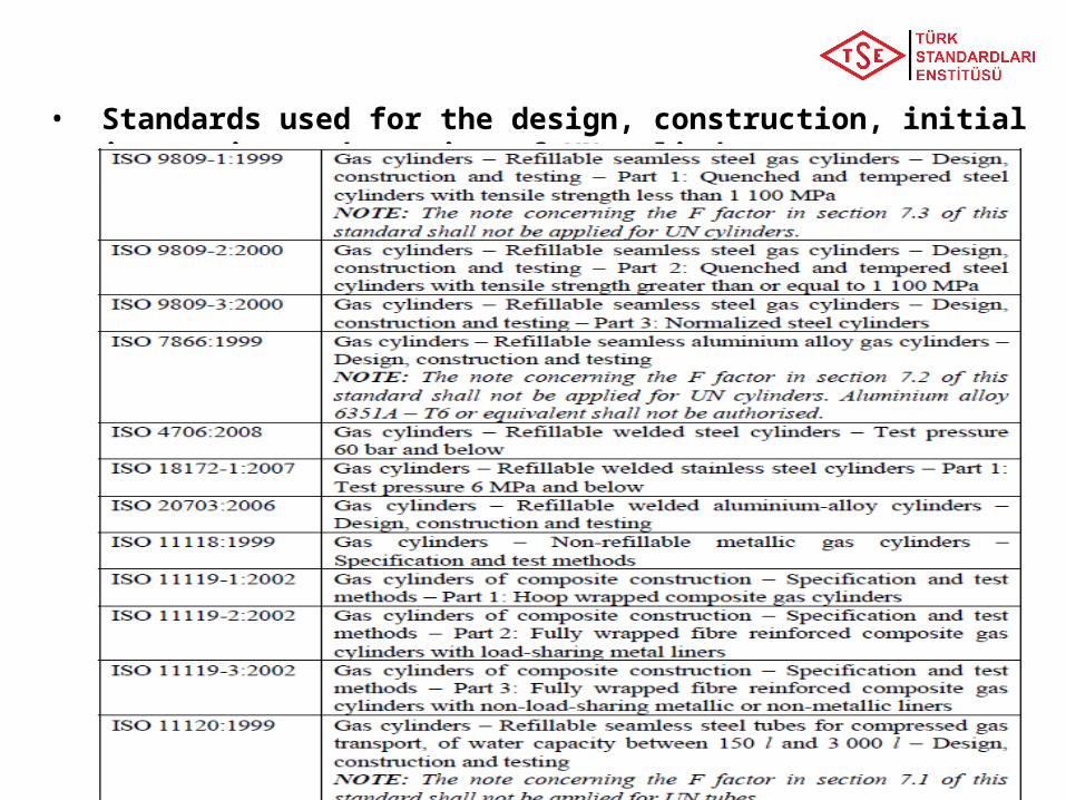
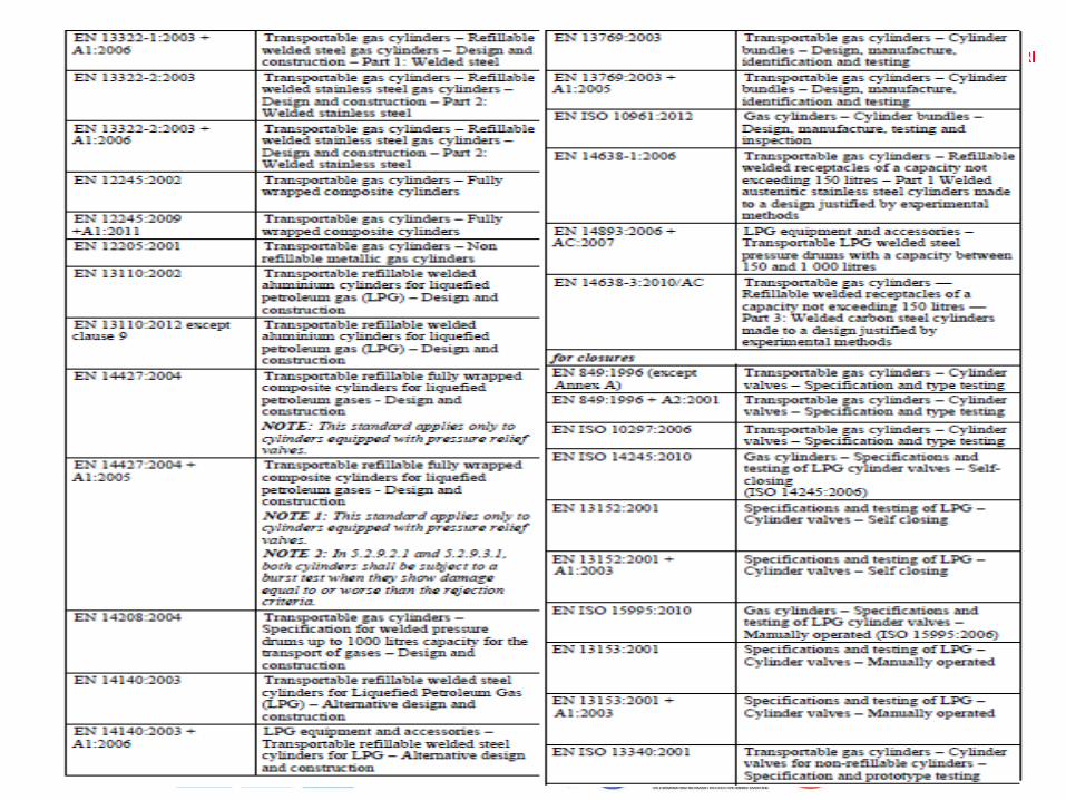
• Standards used for the design, construction, initial inspection and testing of UN cylinders:
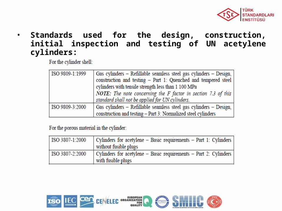
• Standards used for the design, construction, initial inspection and testing of UN acetylene cylinders:
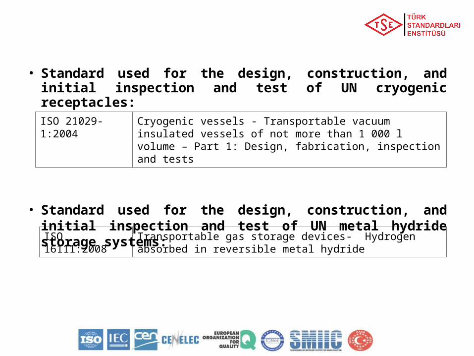
• Standard used for the design, construction, and initial inspection and test of UN cryogenic receptacles:
• Standard used for the design, construction, and initial inspection and test of UN metal hydride storage systems:
ISO 21029-1:2004 Cryogenic vessels - Transportable vacuum insulated vessels of not more than 1 000 l volume – Part 1: Design, fabrication, inspection and tests
ISO 16111:2008 Transportable gas storage devices- Hydrogen absorbed in reversible metal hydride
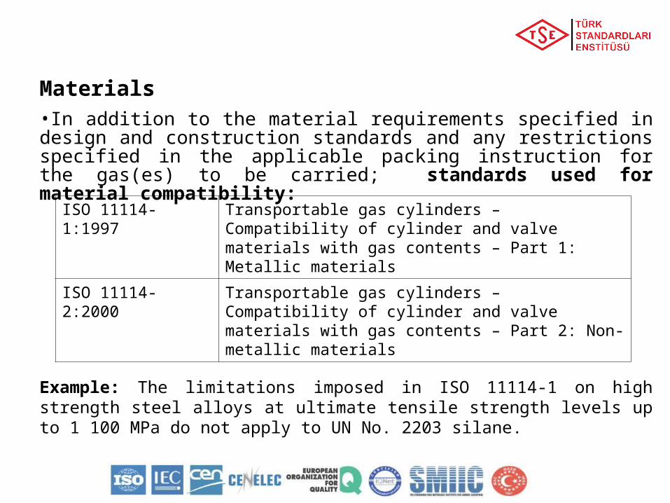
Materials•In addition to the material requirements specified in design and construction standards and any restrictions specified in the applicable packing instruction for the gas(es) to be carried; standards used for material compatibility:
Example: The limitations imposed in ISO 11114-1 on high strength steel alloys at ultimate tensile strength levels up to 1 100 MPa do not apply to UN No. 2203 silane.
ISO 11114-1:1997 Transportable gas cylinders – Compatibility of cylinder and valve materials with gas contents – Part 1: Metallic materials
ISO 11114-2:2000 Transportable gas cylinders – Compatibility of cylinder and valve materials with gas contents – Part 2: Non-metallic materials
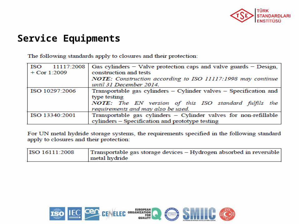
Service Equipments
Non-UN Pressure Receptacles Designed, constructed and tested according to referenced standards Not designed, constructed and tested according to referenced standards
• To reflect scientific and technical progress or where no standard is referenced in ADR or to deal with specific aspects not addressed in a standard referenced in ADR, the competent authority may recognize the use of a technical code providing the same level of safety.
• In the type approval the issuing body shall specify the procedure for periodic inspections if the standards referenced in ADR are not applicable or shall not be applied.
• The competent authority shall transmit to the secretariat of UNECE a list of the technical codes that it recognizes. The list should include the following details: name and date of the code, purpose of the code and details of where it may be obtained.
• The secretariat shall make this information publicly available on its website.• A standard which has been adopted for reference in a future edition of the
ADR may be approved by the competent authority for use without notifying the secretariat of UNECE.
• The requirements of 6.2.1, 6.2.3 and the following requirements however shall be met.
Testing and Inspections• New pressure receptacles, other than closed
cryogenic receptacles and metal hydride storage systems, shall be subjected to testing and inspection during and after manufacture in accordance with the applicable design standards as follows:
• On an adequate sample of pressure receptacles:
a) Testing of the mechanical characteristics of the material of construction
• Verification of the minimum wall thickness• Verification of the homogeneity of the material for each
manufacturing batch • Inspection of the external and internal conditions of the
pressure receptacles• Inspection of the neck threads• Verification of the conformance with the design standard
Scope of Initial Inspection
• For all pressure receptacles:g)A hydraulic pressure test. Pressure receptacles shall withstand the
test pressure without expansion greater than that allowed in the design specification
NOTE: With the agreement of the competent authority, the hydraulic pressure test may be replaced by a test using a gas, where such an operation does not entail any danger.
h)Inspection and assessment of manufacturing defects and either repairing them or rendering the pressure receptacles unserviceable. In the case of welded pressure receptacles, particular attention shall be paid to the quality of the welds
i) An inspection of the markings on the pressure receptaclesj) In addition, pressure receptacles intended for the carriage of UN
No. 1001 acetylene, dissolved, and UN No. 3374 acetylene, solvent free, shall be inspected to ensure proper installation and condition of the porous material and, if applicable, the quantity of solvent.
Scope of Initial Inspection
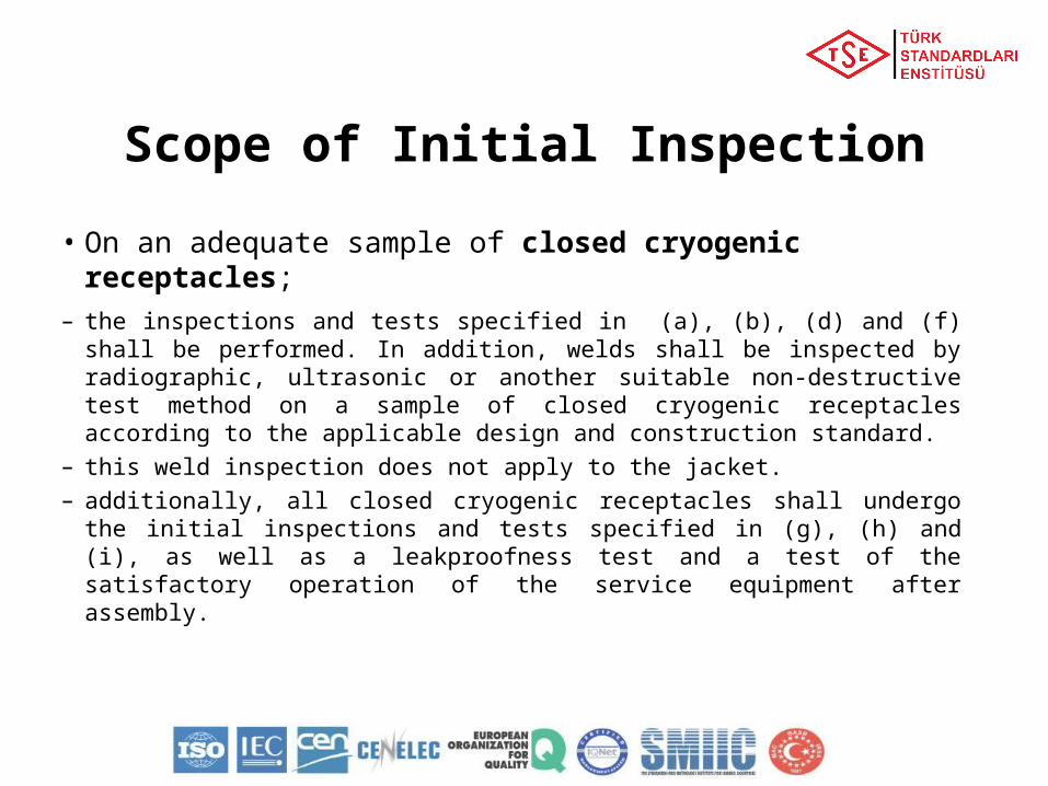
• On an adequate sample of closed cryogenic receptacles;
– the inspections and tests specified in (a), (b), (d) and (f) shall be performed. In addition, welds shall be inspected by radiographic, ultrasonic or another suitable non-destructive test method on a sample of closed cryogenic receptacles according to the applicable design and construction standard.
– this weld inspection does not apply to the jacket.– additionally, all closed cryogenic receptacles shall undergo the
initial inspections and tests specified in (g), (h) and (i), as well as a leakproofness test and a test of the satisfactory operation of the service equipment after assembly.
Scope of Initial Inspection
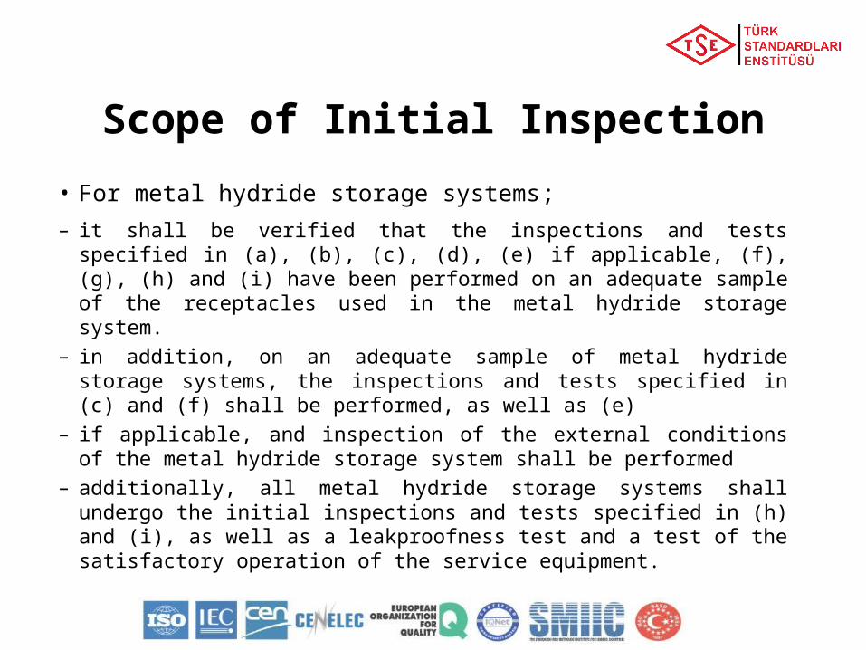
• For metal hydride storage systems;
– it shall be verified that the inspections and tests specified in (a), (b), (c), (d), (e) if applicable, (f), (g), (h) and (i) have been performed on an adequate sample of the receptacles used in the metal hydride storage system.
– in addition, on an adequate sample of metal hydride storage systems, the inspections and tests specified in (c) and (f) shall be performed, as well as (e)
– if applicable, and inspection of the external conditions of the metal hydride storage system shall be performed
– additionally, all metal hydride storage systems shall undergo the initial inspections and tests specified in (h) and (i), as well as a leakproofness test and a test of the satisfactory operation of the service equipment.
Scope of Initial Inspection
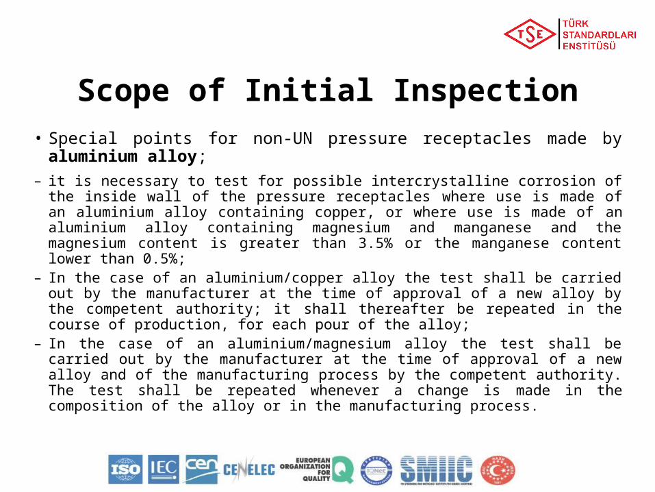
• Special points for non-UN pressure receptacles made by aluminium alloy;
– it is necessary to test for possible intercrystalline corrosion of the inside wall of the pressure receptacles where use is made of an aluminium alloy containing copper, or where use is made of an aluminium alloy containing magnesium and manganese and the magnesium content is greater than 3.5% or the manganese content lower than 0.5%;
– In the case of an aluminium/copper alloy the test shall be carried out by the manufacturer at the time of approval of a new alloy by the competent authority; it shall thereafter be repeated in the course of production, for each pour of the alloy;
– In the case of an aluminium/magnesium alloy the test shall be carried out by the manufacturer at the time of approval of a new alloy and of the manufacturing process by the competent authority. The test shall be repeated whenever a change is made in the composition of the alloy or in the manufacturing process.
Scope of Initial Inspection
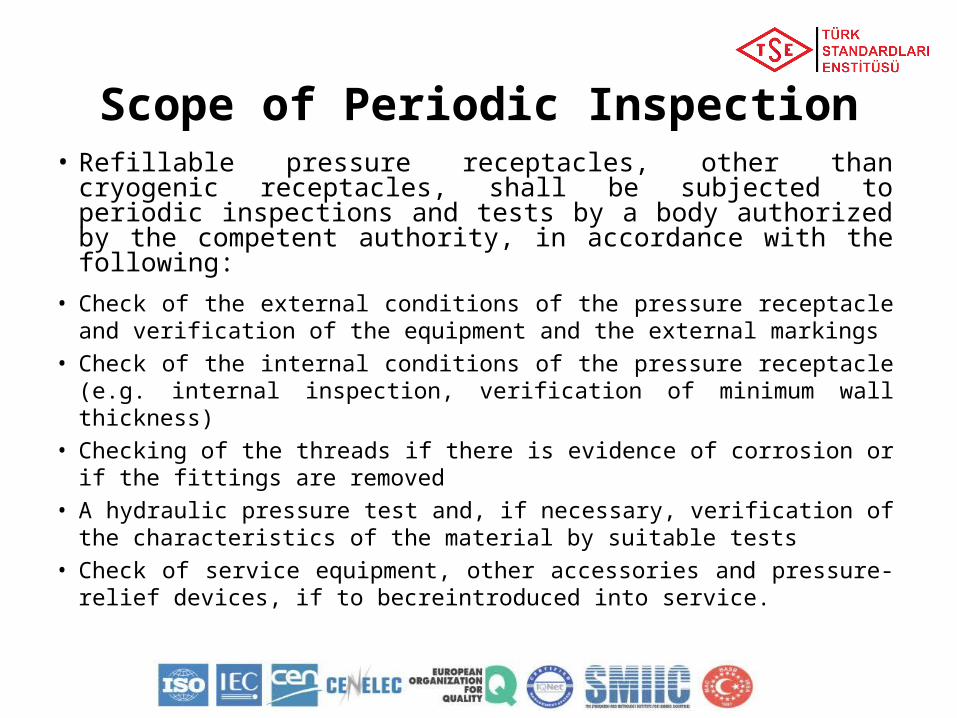
Scope of Periodic Inspection• Refillable pressure receptacles, other than cryogenic
receptacles, shall be subjected to periodic inspections and tests by a body authorized by the competent authority, in accordance with the following:
• Check of the external conditions of the pressure receptacle and verification of the equipment and the external markings
• Check of the internal conditions of the pressure receptacle (e.g. internal inspection, verification of minimum wall thickness)
• Checking of the threads if there is evidence of corrosion or if the fittings are removed
• A hydraulic pressure test and, if necessary, verification of the characteristics of the material by suitable tests
• Check of service equipment, other accessories and pressure-relief devices, if to becreintroduced into service.
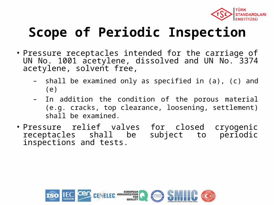
• Pressure receptacles intended for the carriage of UN No. 1001 acetylene, dissolved and UN No. 3374 acetylene, solvent free,
– shall be examined only as specified in (a), (c) and (e)– In addition the condition of the porous material (e.g.
cracks, top clearance, loosening, settlement) shall be examined.
• Pressure relief valves for closed cryogenic receptacles shall be subject to periodic inspections and tests.
Scope of Periodic Inspection
Frequencies of Periodic Inspections
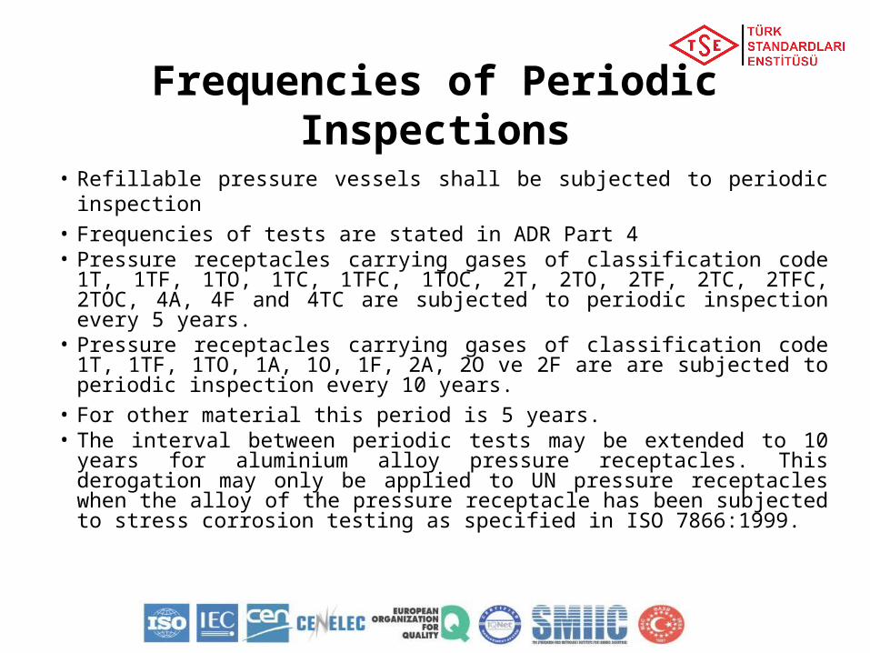
• Refillable pressure vessels shall be subjected to periodic inspection
• Frequencies of tests are stated in ADR Part 4• Pressure receptacles carrying gases of classification code 1T,
1TF, 1TO, 1TC, 1TFC, 1TOC, 2T, 2TO, 2TF, 2TC, 2TFC, 2TOC, 4A, 4F and 4TC are subjected to periodic inspection every 5 years.
• Pressure receptacles carrying gases of classification code 1T, 1TF, 1TO, 1A, 1O, 1F, 2A, 2O ve 2F are are subjected to periodic inspection every 10 years.
• For other material this period is 5 years.• The interval between periodic tests may be extended to 10
years for aluminium alloy pressure receptacles. This derogation may only be applied to UN pressure receptacles when the alloy of the pressure receptacle has been subjected to stress corrosion testing as specified in ISO 7866:1999.
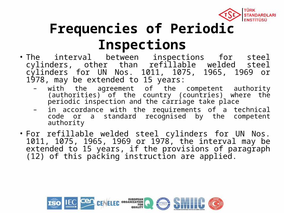
• The interval between inspections for steel cylinders, other than refillable welded steel cylinders for UN Nos. 1011, 1075, 1965, 1969 or 1978, may be extended to 15 years:
– with the agreement of the competent authority (authorities) of the country (countries) where the periodic inspection and the carriage take place
– in accordance with the requirements of a technical code or a standard recognised by the competent authority
• For refillable welded steel cylinders for UN Nos. 1011, 1075, 1965, 1969 or 1978, the interval may be extended to 15 years, if the provisions of paragraph (12) of this packing instruction are applied.
Frequencies of Periodic Inspections
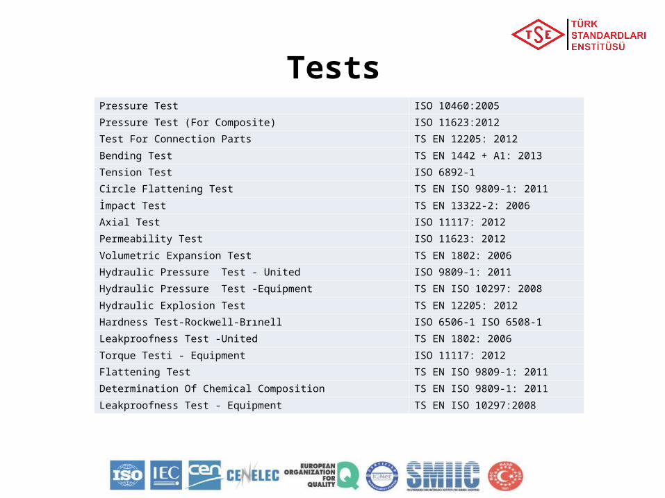
TestsPressure Test ISO 10460:2005
Pressure Test (For Composite) ISO 11623:2012
Test For Connection Parts TS EN 12205: 2012
Bending Test TS EN 1442 + A1: 2013
Tension Test ISO 6892-1
Circle Flattening Test TS EN ISO 9809-1: 2011
İmpact Test TS EN 13322-2: 2006
Axial Test ISO 11117: 2012
Permeability Test ISO 11623: 2012
Volumetric Expansion Test TS EN 1802: 2006
Hydraulic Pressure Test - United ISO 9809-1: 2011
Hydraulic Pressure Test -Equipment TS EN ISO 10297: 2008
Hydraulic Explosion Test TS EN 12205: 2012
Hardness Test-Rockwell-Brınell ISO 6506-1 ISO 6508-1
Leakproofness Test -United TS EN 1802: 2006
Torque Testi - Equipment ISO 11117: 2012
Flattening Test TS EN ISO 9809-1: 2011
Determination Of Chemical Composition TS EN ISO 9809-1: 2011
Leakproofness Test - Equipment TS EN ISO 10297:2008
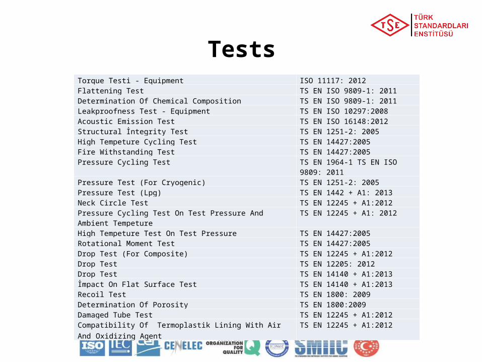
Torque Testi - Equipment ISO 11117: 2012 Flattening Test TS EN ISO 9809-1: 2011 Determination Of Chemical Composition TS EN ISO 9809-1: 2011 Leakproofness Test - Equipment TS EN ISO 10297:2008 Acoustic Emission Test TS EN ISO 16148:2012 Structural İntegrity Test TS EN 1251-2: 2005 High Tempeture Cycling Test TS EN 14427:2005 Fire Withstanding Test TS EN 14427:2005 Pressure Cycling Test TS EN 1964-1 TS EN ISO 9809: 2011 Pressure Test (For Cryogenic) TS EN 1251-2: 2005 Pressure Test (Lpg) TS EN 1442 + A1: 2013 Neck Circle Test TS EN 12245 + A1:2012 Pressure Cycling Test On Test Pressure And Ambient Tempeture TS EN 12245 + A1: 2012 High Tempeture Test On Test Pressure TS EN 14427:2005 Rotational Moment Test TS EN 14427:2005 Drop Test (For Composite) TS EN 12245 + A1:2012 Drop Test TS EN 12205: 2012 Drop Test TS EN 14140 + A1:2013 İmpact On Flat Surface Test TS EN 14140 + A1:2013 Recoil Test TS EN 1800: 2009 Determination Of Porosity TS EN 1800:2009 Damaged Tube Test TS EN 12245 + A1:2012 Compatibility Of Termoplastik Lining With Air And Oxidizing Agent TS EN 12245 + A1:2012
Tests
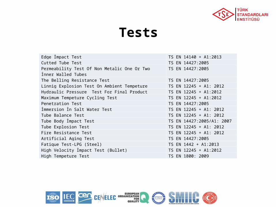
Edge İmpact Test TS EN 14140 + A1:2013 Cutted Tube Test TS EN 14427:2005 Permeability Test Of Non Metalic One Or Two İnner Walled Tubes TS EN 14427:2005 The Belling Resistance Test TS EN 14427:2005 Linnig Explosion Test On Ambient Tempeture TS EN 12245 + A1: 2012 Hydraulic Pressure Test For Final Product TS EN 12245 + A1:2012 Maximum Tempeture Cycling Test TS EN 12245 + A1:2012 Penetration Test TS EN 14427:2005 İmmersion İn Salt Water Test TS EN 12245 + A1: 2012 Tube Balance Test TS EN 12245 + A1: 2012 Tube Body İmpact Test TS EN 14427:2005/A1: 2007 Tube Explosion Test TS EN 12245 + A1: 2012 Fire Resistance Test TS EN 12245 + A1: 2012 Artificial Aging Test TS EN 14427:2005 Fatique Test-LPG (Steel) TS EN 1442 + A1:2013 High Velocity İmpact Test (Bullet) TS EN 12245 + A1:2012 High Tempeture Test TS EN 1800: 2009
Tests
Marking• Refillable UN pressure receptacles shall be marked clearly
and legibly with certification, operational and manufacturing marks.
• These marks shall be permanently affixed (e.g. stamped, engraved, or etched) on the pressure receptacle.
• The marks shall be on the shoulder, top end or neck of the pressure receptacle or on a permanently affixed component of the pressure receptacle (e.g. welded collar or corrosion resistant plate welded on the outer jacket of a closed cryogenic receptacle).
• Except for the UN packaging symbol, the minimum size of the marks shall be 5 mm for pressure receptacles with a diameter greater than or equal to 140 mm and 2.5 mm for pressure receptacles with a diameter less than 140 mm.
• The minimum size of the UN packaging symbol shall be 10 mm for pressure receptacles with a diameter greater than or equal to 140 mm and 5 mm for pressure receptacles with a diameter less than 140 mm.
• Non-refillable pressure receptacles marked with «DO NOT REFILL» in letters of at least 5 mm in height are required.
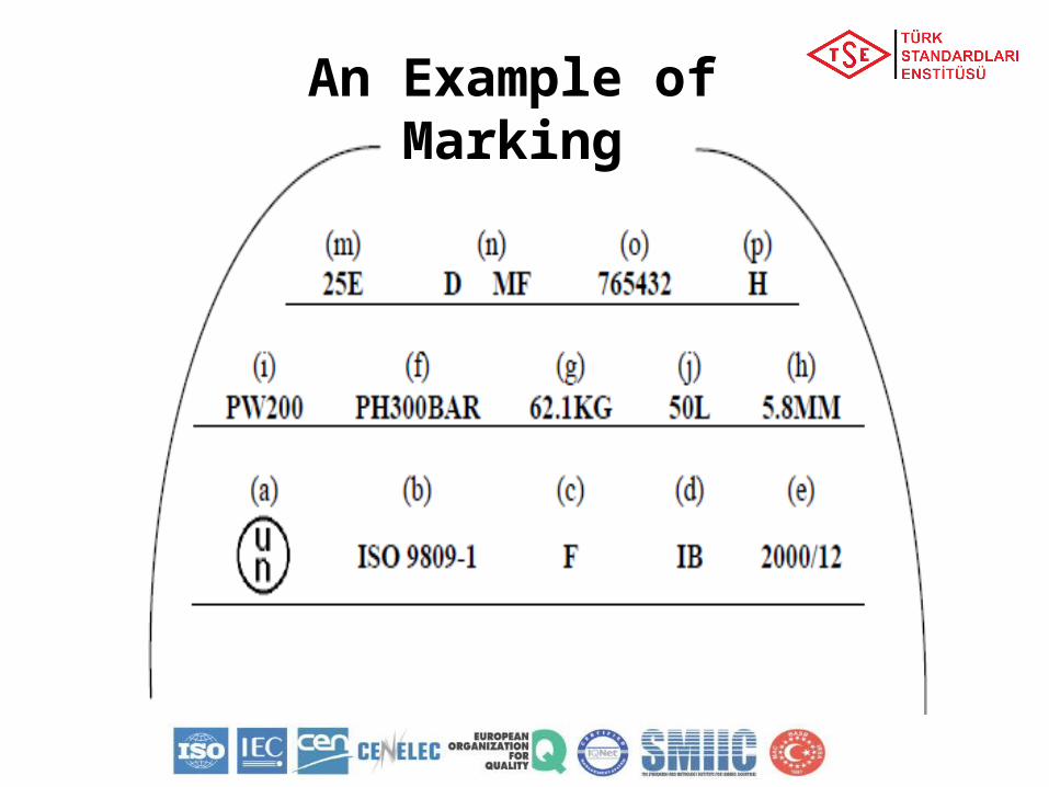
An Example of Marking
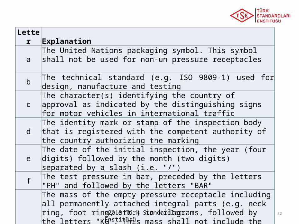
LetterExplanation
aThe United Nations packaging symbol. This symbol shall not be used for non-un pressure receptacles
bThe technical standard (e.g. ISO 9809-1) used for design, manufacture and testing
cThe character(s) identifying the country of approval as indicated by the distinguishing signs for motor vehicles in international traffic
dThe identity mark or stamp of the inspection body that is registered with the competent authority of the country authorizing the marking
eThe date of the initial inspection, the year (four digits) followed by the month (two digits) separated by a slash (i.e. "/")
fThe test pressure in bar, preceded by the letters "PH" and followed by the letters "BAR"
g
The mass of the empty pressure receptacle including all permanently attached integral parts (e.g. neck ring, foot ring, etc.) in kilograms, followed by the letters "KG". This mass shall not include the mass of valve, valve cap or valve guard, any coating or porous material for acetylene. The mass shall be expressed to three significant figures rounded up to the last digit. For cylinders of less than 1 kg, the mass shall be expressed to two significant figures rounded up to the last digit. In the case of pressure receptacles for UN No. 1001 acetylene, dissolved and UN No. 3374 acetylene, solvent free, at least one decimal shall be shown after the decimal point and two digits for pressure receptacles of less than 1 kg;
©2013 Türk Standardları Enstitüsü 32
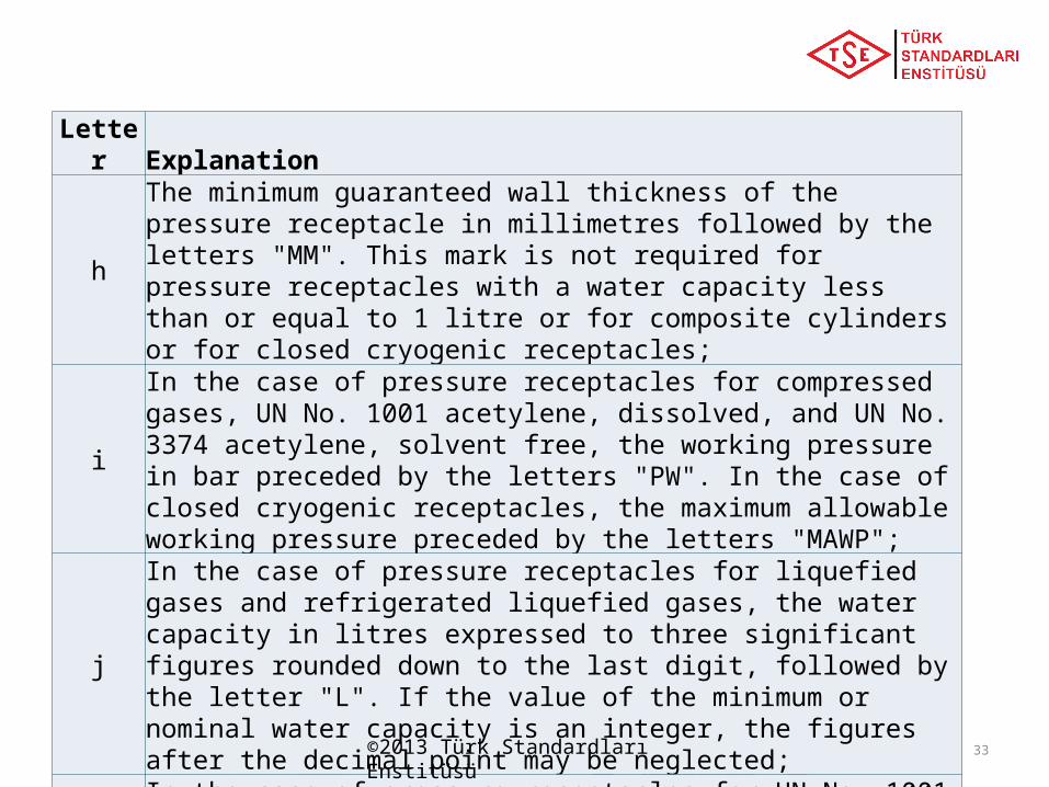
LetterExplanation
h
The minimum guaranteed wall thickness of the pressure receptacle in millimetres followed by the letters "MM". This mark is not required for pressure receptacles with a water capacity less than or equal to 1 litre or for composite cylinders or for closed cryogenic receptacles;
i
In the case of pressure receptacles for compressed gases, UN No. 1001 acetylene, dissolved, and UN No. 3374 acetylene, solvent free, the working pressure in bar preceded by the letters "PW". In the case of closed cryogenic receptacles, the maximum allowable working pressure preceded by the letters "MAWP";
j
In the case of pressure receptacles for liquefied gases and refrigerated liquefied gases, the water capacity in litres expressed to three significant figures rounded down to the last digit, followed by the letter "L". If the value of the minimum or nominal water capacity is an integer, the figures after the decimal point may be neglected;
k
In the case of pressure receptacles for UN No. 1001 acetylene, dissolved, the total of the mass of the empty receptacle, the fittings and accessories not removed during filling, any coating, the porous material, the solvent and the saturation gas expressed to three significant figures rounded down to the last digit followed by the letters "KG". At least one decimal shall be shown after the decimal point. For pressure receptacles of less than 1 kg, the mass shall be expressed to two significant figures rounded down to the last digit;
©2013 Türk Standardları Enstitüsü 33
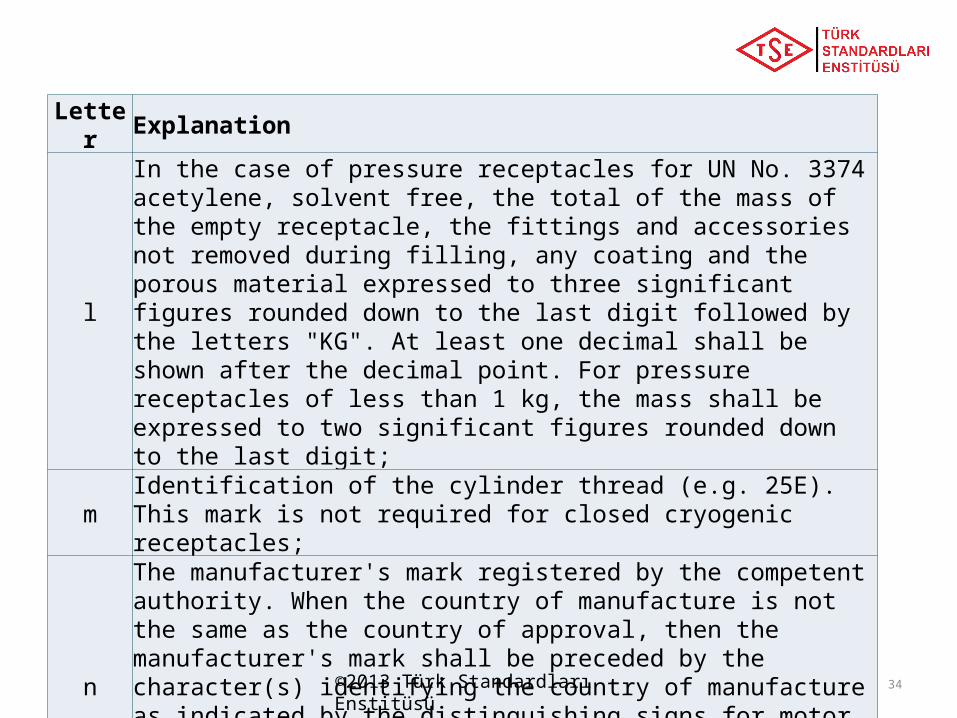
LetterExplanation
l
In the case of pressure receptacles for UN No. 3374 acetylene, solvent free, the total of the mass of the empty receptacle, the fittings and accessories not removed during filling, any coating and the porous material expressed to three significant figures rounded down to the last digit followed by the letters "KG". At least one decimal shall be shown after the decimal point. For pressure receptacles of less than 1 kg, the mass shall be expressed to two significant figures rounded down to the last digit;
mIdentification of the cylinder thread (e.g. 25E). This mark is not required for closed cryogenic receptacles;
n
The manufacturer's mark registered by the competent authority. When the country of manufacture is not the same as the country of approval, then the manufacturer's mark shall be preceded by the character(s) identifying the country of manufacture as indicated by the distinguishing signs for motor vehicles in international traffic3. The country mark and the manufacturer’s mark shall be separated by a space or slash;
o The serial number assigned by the manufacturer;
p
In the case of steel pressure receptacles and composite pressure receptacles with steel liner intended for the carriage of gases with a risk of hydrogen embrittlement, the letter "H" showing compatibility of the steel (see ISO 11114-1:1997).
©2013 Türk Standardları Enstitüsü 34