Embed Size (px)
Citation preview
Certificate in Computer-aided Engineering Competences (2303) Qualification Handbook
www.cityandguilds.com November 2006 Version 1.0

About City & Guilds City & Guilds is the UK’s leading provider of vocational qualifications, offering over 500 awards across a wide range of industries, and progressing from entry level to the highest levels of professional achievement. With over 8500 centres in 100 countries, City & Guilds is recognised by employers worldwide for providing qualifications that offer proof of the skills they need to get the job done. City & Guilds Group The City & Guilds Group includes ILM (the Institute of Leadership & Management) providing management qualifications, learning materials and membership services and NPTC which offers land-based qualifications and membership services. City & Guilds also manages the Engineering Council Examinations on behalf of the Engineering Council. Equal opportunities City & Guilds fully supports the principle of equal opportunities and we are committed to satisfying this principle in all our activities and published material. A copy of our equal opportunities policy statement Access to assessment and qualifications is available on the City & Guilds website. Copyright The content of this document is, unless otherwise indicated, © The City and Guilds of London Institute 2005 and may not be copied, reproduced or distributed without prior written consent. However, approved City & Guilds centres and learners studying for City & Guilds qualifications may photocopy this document free of charge and/or include a locked PDF version of it on centre intranets on the following conditions:
• centre staff may copy the material only for the purpose of teaching learners working towards a City & Guilds qualification, or for internal administration purposes
• learners may copy the material only for their own use when working towards a City & Guilds qualification
• the Standard Copying Conditions on the City & Guilds website. Please note: National Occupational Standards are not © The City and Guilds of London Institute. Please check the conditions upon which they may be copied with the relevant Sector Skills Council. Publications City & Guilds publications are available on the City & Guilds website or from our Publications Sales department at the address below or by telephoning +44 (0)20 7294 2850 or faxing +44 (0)20 7294 3387. Every effort has been made to ensure that the information contained in this publication is true and correct at the time of going to press. However, City & Guilds’ products and services are subject to continuous development and improvement and the right is reserved to change products and services from time to time. City & Guilds cannot accept liability for loss or damage arising from the use of information in this publication. City & Guilds 1 Giltspur Street London EC1A 9DD T +44 (0)20 7294 2800 www.cityandguilds.com F +44 (0)20 7294 2400 [email protected]

Certificate in Computer-aided Engineering Competences (2303)
Qualification Handbook Version 1.0

This page is intentionally blank

Contents
1 Introduction 7 2 Test specification 11 3 Unit Requirements 16

This page is intentionally blank

7
1 Introduction
About this document The certificates described in this handbook relate to Computer-aided Engineering Parts 1, 2 and 3. This document is the edited web-based version of the original paper-based handbook, the course content has not been altered.
Registration and Result Submission Candidates must register at the beginning of there course electronically on Walled Garden website (www.walled-garden.com) or by Form S, tick Named Registration. Registrations are valid for 4 years. Candidates must be registered at least 28 days before component results are submitted.
Results submission When assessments have been successfully completed, candidate results should be submitted either through the Walled Garden website (www.walled-garden.com) or by Form S, tick Results submission for all non-timetabled components. For component numbers 001-006 enter each component number with D, C or P to indicate the grade achieved. For all other component numbers enter each component number claimed followed by P. Additional components may also be claimed but are not necessary for the full award. Centres should note that results will not be processed by City & Guilds until verification records are complete.
Certificate Structure The assessments related to the units included in these certificates are written, practical and assignment based. Part 1 - Certificate in Computer-aided Engineering 2303-001 Unit 1 - Basic CNC 2303-002 Unit 2 - Basic CAD 2303-003 Unit 3 - Basic Robotics 2303-004 Unit 4 - Basic PLC In addition there are two optional units in 2303-005 Unit 5 - Basic computing skills 2303-006 Unit 6 - Basic digital electronics Part 2 - Certificate in NC/CNC Machine Setting and Operation 2303-007 Unit 1 - Safety procedures 2303-008 Unit 2 - Data input and preparation 2303-009 Unit 3 - Work and tool preparation 2303-010 Unit 4 - CNC machine operation Part 2 – Certificate in NC/CNC Part Programming 2303-011 Unit 1 - Plan production of part program 2303-012 Unit 2 - Write/prove part program 2303-013 Unit 3 - Produce components
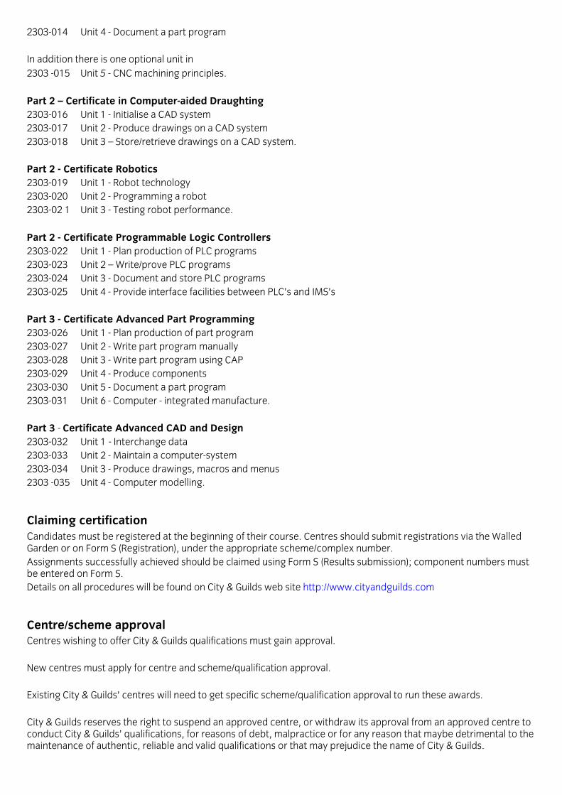
2303-014 Unit 4 - Document a part program In addition there is one optional unit in 2303 -015 Unit 5 - CNC machining principles. Part 2 – Certificate in Computer-aided Draughting 2303-016 Unit 1 - Initialise a CAD system 2303-017 Unit 2 - Produce drawings on a CAD system 2303-018 Unit 3 – Store/retrieve drawings on a CAD system. Part 2 - Certificate Robotics 2303-019 Unit 1 - Robot technology 2303-020 Unit 2 - Programming a robot 2303-02 1 Unit 3 - Testing robot performance. Part 2 - Certificate Programmable Logic Controllers 2303-022 Unit 1 - Plan production of PLC programs 2303-023 Unit 2 – Write/prove PLC programs 2303-024 Unit 3 - Document and store PLC programs 2303-025 Unit 4 - Provide interface facilities between PLC’s and IMS’s Part 3 - Certificate Advanced Part Programming 2303-026 Unit 1 - Plan production of part program 2303-027 Unit 2 - Write part program manually 2303-028 Unit 3 - Write part program using CAP 2303-029 Unit 4 - Produce components 2303-030 Unit 5 - Document a part program 2303-031 Unit 6 - Computer - integrated manufacture. Part 3 - Certificate Advanced CAD and Design 2303-032 Unit 1 - Interchange data 2303-033 Unit 2 - Maintain a computer-system 2303-034 Unit 3 - Produce drawings, macros and menus 2303 -035 Unit 4 - Computer modelling.
Claiming certification Candidates must be registered at the beginning of their course. Centres should submit registrations via the Walled Garden or on Form S (Registration), under the appropriate scheme/complex number. Assignments successfully achieved should be claimed using Form S (Results submission); component numbers must be entered on Form S. Details on all procedures will be found on City & Guilds web site http://www.cityandguilds.com
Centre/scheme approval Centres wishing to offer City & Guilds qualifications must gain approval. New centres must apply for centre and scheme/qualification approval. Existing City & Guilds’ centres will need to get specific scheme/qualification approval to run these awards. City & Guilds reserves the right to suspend an approved centre, or withdraw its approval from an approved centre to conduct City & Guilds’ qualifications, for reasons of debt, malpractice or for any reason that maybe detrimental to the maintenance of authentic, reliable and valid qualifications or that may prejudice the name of City & Guilds.

9
Course design Tutors/assessors should familiarise themselves with the structure and content of the award before designing an appropriate course; in particular they are advised to consider the knowledge and understanding requirements of the relevant N/SVQ. City & Guilds does not itself provide courses of instruction or specify entry requirements. As long as the requirements for the award are met, tutors/assessors may design courses of study in any way that they feel best meets the needs and capabilities of the candidates. Centres may wish to introduce other topics as part of the programme which will not be assessed through the qualifications, eg to meet local needs. It is recommended that centres cover the following in the delivery of the course, where appropriate:
• Health and safety considerations, in particular the need to impress to candidates that they must preserve the health and safety of others as well as themselves
• Key Skills (such as Communication, Application of Number, Information technology, Working with others, Improving own learning and performance, Problem solving)
• Equal opportunities • Spiritual, moral, social and cultural issues • Environmental education, related European issues.
Assessments There are three main assessment methods and it will usually be necessary to combine at least two of them to assemble sufficient evidence that the candidate has met, or can meet, the requirements of the syllabus. They are
a. observation of performance over time or on specified occasions in the workplace or in a simulated working environment
b. setting assignments, projects, practical tasks c. written or oral tests.
Whichever mode of assessment is used (i.e. oral and/or written), it is required that the testing of knowledge and understanding is undertaken in close association with the assessment of performance. For example, following an assessment of performance in machining a simple component in which the candidate has been observed going through the correct actions in the correct sequence, the assessor could then ask questions relating to the common types of work holding methods and the action to be taken if the component is not secure. With regard to written tests, it is expected that these will be taken within four weeks of the associated performance assessment. Candidates may have prior sight of the assessments but should not be permitted to take assessment material away or to make notes. Candidates' answers must reflect the level of knowledge indicated by the content and scope of a clear answer guide which assessors must provide and which should accommodate any company specific facts and answers. Candidates should be given maximum opportunity to show their knowledge and any reasonable help may be given by assessors to enable candidates to do this. There is no time limit in which the assessments must be completed - the assessor will be expected to use his/her discretion in this matter. Neither is there any limit to the number of attempts candidates may make in order to achieve success. Only those questions to which the candidate gives incorrect or insufficient responses need to be attempted again. It is recommended that re-assessment should be conducted orally. Assessors must inform candidates as soon as possible of their achievement in the assessments and where insufficient knowledge evidence is obtained, advice and guidance should be given to enable candidates to meet the required standard on subsequent assessment occasions. The marking of both oral and written assessments must be undertaken by an approved assessor. It is important for the purposes of verification that records of Candidates' answers, both oral and written, are kept.

Written tests Centres will devise their own questions for the written tests, using the Test Specification as a guidance. Questions should be drawn up in consultation with the External Verifier. The scope of the written test should be in accordance with the requirements of the elements. (see Test Specifications), and should be kept as short as possible. Tests must be conducted under exam conditions.
Oral questions Oral questioning can be conducted through conversation, direct questioning or interviewing. Candidates may be questioned
• while carrying out an activity
• immediately on completion of an activity The timing of the questioning will depend on the nature of the activity. Throughout the syllabus, in order to meet the knowledge criteria, recommended oral questions are indicated by an asterisk. Candidates may be asked follow-up questions to ensure they fully understand what is required by the assessment. Oral questioning can be difficult and often assessors will need to apply common sense and judgement.
Assignments/Projects Assignments or projects must contain the following information for candidates
• the theme or purpose
• unit/elements it covers/refers to
• clear instructions on work to be undertaken and the length/format/presentation required
• date for completion
• criteria for success.
11
2 Test specifications
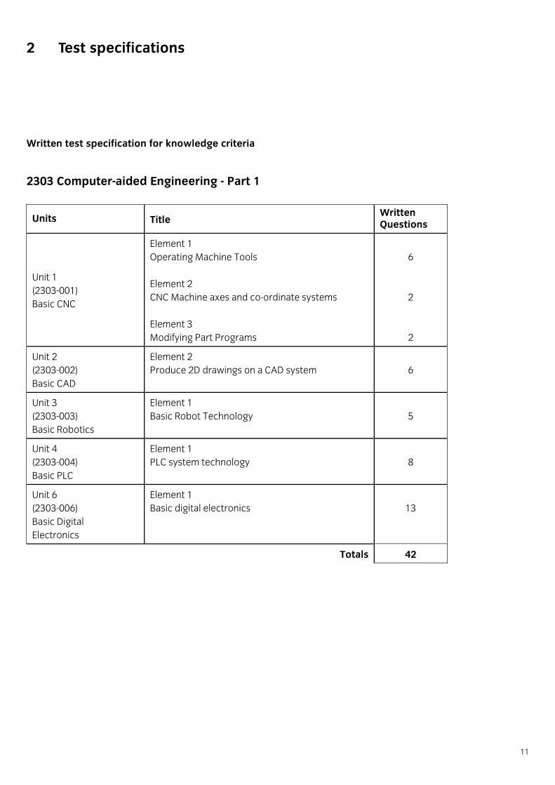
Written test specification for knowledge criteria
2303 Computer-aided Engineering - Part 1
Units Title Written Questions
Unit 1 (2303-001) Basic CNC
Element 1 Operating Machine Tools Element 2 CNC Machine axes and co-ordinate systems Element 3 Modifying Part Programs
6 2 2
Unit 2 (2303-002) Basic CAD
Element 2 Produce 2D drawings on a CAD system
6
Unit 3 (2303-003) Basic Robotics
Element 1 Basic Robot Technology
5
Unit 4 (2303-004) Basic PLC
Element 1 PLC system technology
8
Unit 6 (2303-006) Basic Digital Electronics
Element 1 Basic digital electronics
13
Totals 42
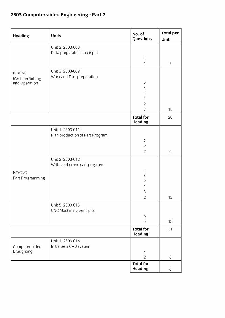
2303 Computer-aided Engineering - Part 2
Heading Units No. of Questions
Total per
Unit
Unit 2 (2303-008) Data preparation and input
1 1 2
NC/CNC Machine Setting and Operation
Unit 3 (2303-009) Work and Tool preparation
3 4 1 1 2 7 18
Total for Heading
20
Unit 1 (2303-011) Plan production of Part Program
2 2 2
6
Unit 2 (2303-012) Write and prove part program.
1 3 2 1 3 2
12
NC/CNC Part Programming
Unit 5 (2303-015) CNC Machining principles
8 5
13
Total for Heading
31
Computer-aided Draughting
Unit 1 (2303-016) Initialise a CAD system
4 2
6
Total for Heading
6
13
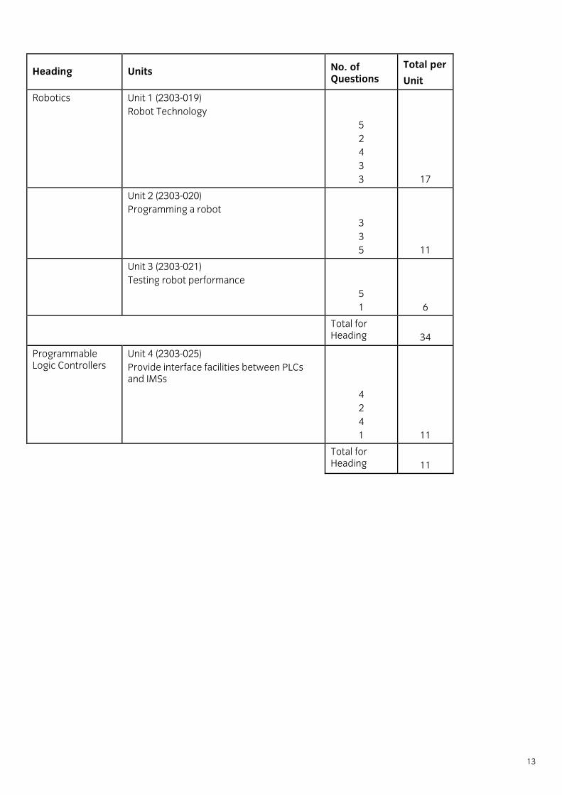
Heading Units No. of Questions
Total per
Unit
Robotics Unit 1 (2303-019) Robot Technology
5 2 4 3 3
17
Unit 2 (2303-020) Programming a robot
3 3 5
11
Unit 3 (2303-021) Testing robot performance
5 1
6
Total for Heading
34
Programmable Logic Controllers
Unit 4 (2303-025) Provide interface facilities between PLCs and IMSs
4 2 4 1
11
Total for Heading
11
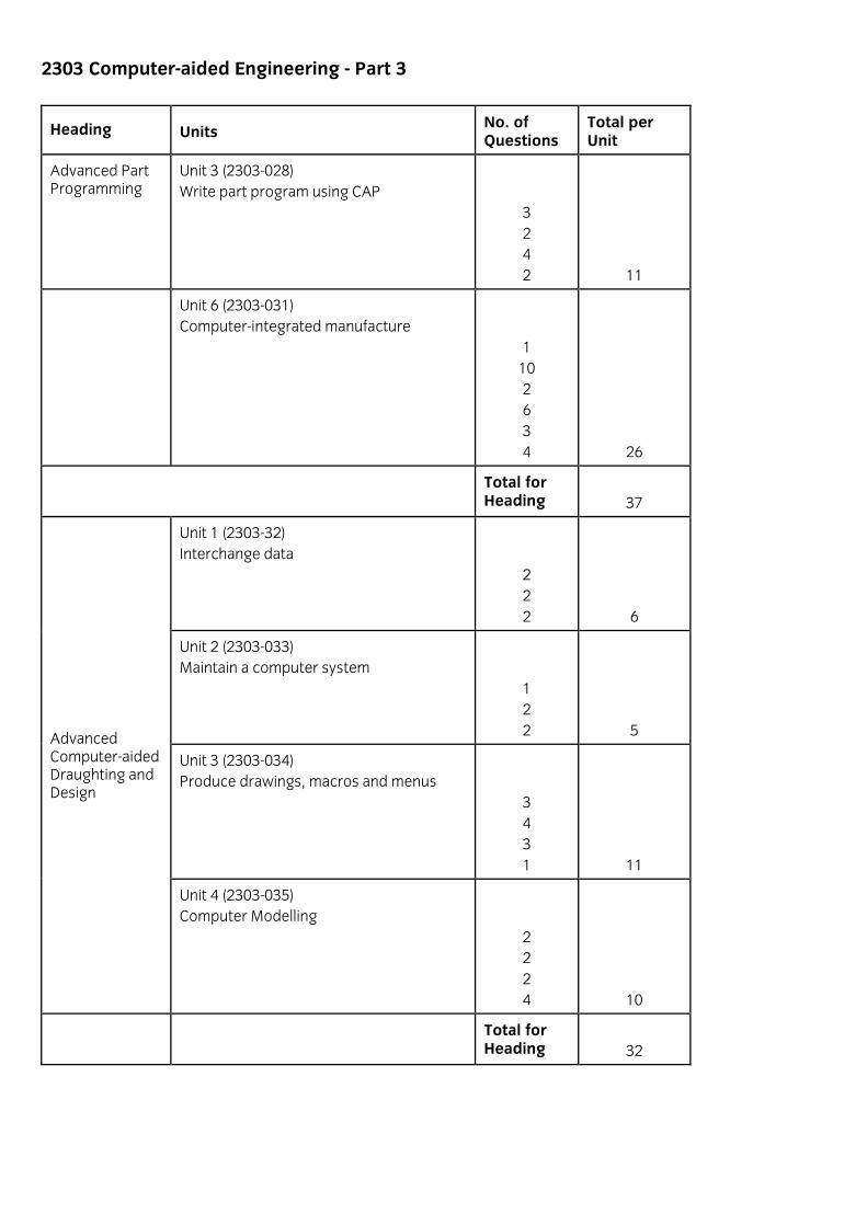
2303 Computer-aided Engineering - Part 3
Heading Units No. of Questions
Total per Unit
Advanced Part Programming
Unit 3 (2303-028) Write part program using CAP
3 2 4 2
11
Unit 6 (2303-031) Computer-integrated manufacture
1 10 2 6 3 4
26
Total for Heading
37
Unit 1 (2303-32) Interchange data
2 2 2
6
Unit 2 (2303-033) Maintain a computer system
1 2 2
5
Unit 3 (2303-034) Produce drawings, macros and menus
3 4 3 1
11
Advanced Computer-aided Draughting and Design
Unit 4 (2303-035) Computer Modelling
2 2 2 4
10
Total for Heading
32

15
Level 2, 3 & 4 Certificate in Computer-aided Engineering Competences (2303)
Part 1 – Computer-aided Engineering
Version 1.0

3 Unit Requirements
Part 1 – Computer-aided Engineering Unit 1 - Basic CNC
Introduction This unit is intended to provide a practical introduction to CNC Machine Tool Operation and CNC Part Programming based on the specific equipment available, as approved for the course. It thus forms a foundation for the Part 2 schemes in these areas. The unit includes definitions of tool geometry, feeds and speeds, the role of work holding devices machine axes and coordinates; these aspects will be experienced by practical work using conventional machine tools as well as CNC. Participants should have demonstrated the skills and knowledge covered in the Basic Computing Skills Unit either by successful study in this unit or by other means. The conventional and CNC machinery and other equipment used may vary from one centre to another. To maintain integrity of the scheme objectives, however, the hardware and procedures involved will be registered as part of the approval for the course of learning. This unit does not aim at general mastery in any of the above areas of work, but the assessment of the main objectives related to specific course machinery, equipment, procedures and products will be criterion-referenced and will concern mainly practical performances.
Guidance notes on CNC machine setting and operation Course notes a. The scheme does not assume any previous experience of CNC machining nor do the objectives necessarily
require the use of industrial scale CNC machinery; however the equipment used must be approved by the course assessors.
b. By limiting the performance objectives to the machinery, equipment, procedures and products approved for
the course, it is then feasible to take the learning through to full, hands-on practical operation. It is here that the compulsory, criterion-based assessments will be made.
c. Where consideration of the more general aspects is materially helpful (or necessary) to the formation and
comprehension of key concepts, these and other enabling aspects will be included in the learning and subject to graded forms of assessment.
d. The treatment of the potential hazards associated with CNC and other forms of machinery, and the precautions
for minimising them should be a prominent and continuous feature.

17
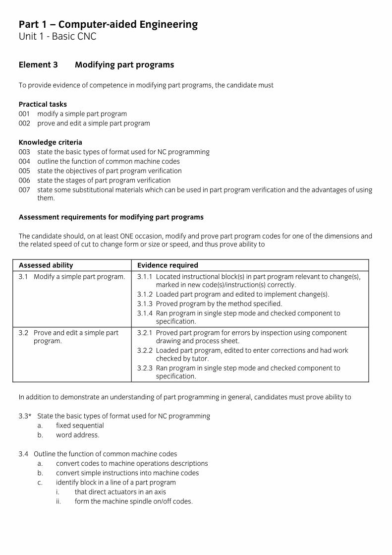
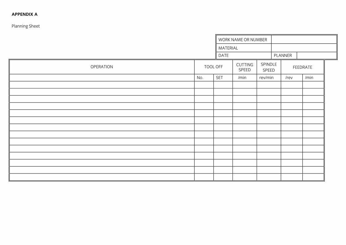
Part 1 – Computer-aided Engineering Unit 1 - Basic CNC Practical assessment notes Tutors should aim to devise practical tasks in machine tool operation which correspond closely to industrial tasks. Typical practical tasks, which show the level to be aimed at, are given below. Example 1 Mount a marked out component for drilling operations (3 holes - 2 with centre dots; 1 without) in a machine vice, mount drill in spindle tool holder, select speed stated in the task sheet; have set-up checked by supervisor; drill 3 holes right through. Example 2 Mount round rough stock in lathe 3-jaw chuck; mount tool in lathe tool post and align tool point to stock centre with suitable back rake angle and tool approach angle settings and select speed stated in the task sheet; have set-up checked by supervisor; read drawing for finished size of turned diameter, set spindle speed to specification and turn down stock diameter, by hand feed, to specification in two stages (i) roughing cut leaving approximately 2mm for (ii) a finish cut to stated size. Example 3 Mount rough stock in a machine vice clamped to the mill table; mount cutter to milling machine spindle; cutter set to work face and feed wheel read or zeroed; move to clear cutter; set spindle speed; have set-up checked by supervisor; read drawing and mill slot right through in 2 stages, by hand, (i) roughing cut leaving approximately 2mm in depth for (ii) a finish cut to stated size. As part of the practical work, students should be asked to complete a planning sheet and a process sheet. Examples of these are given in Appendices A and B.
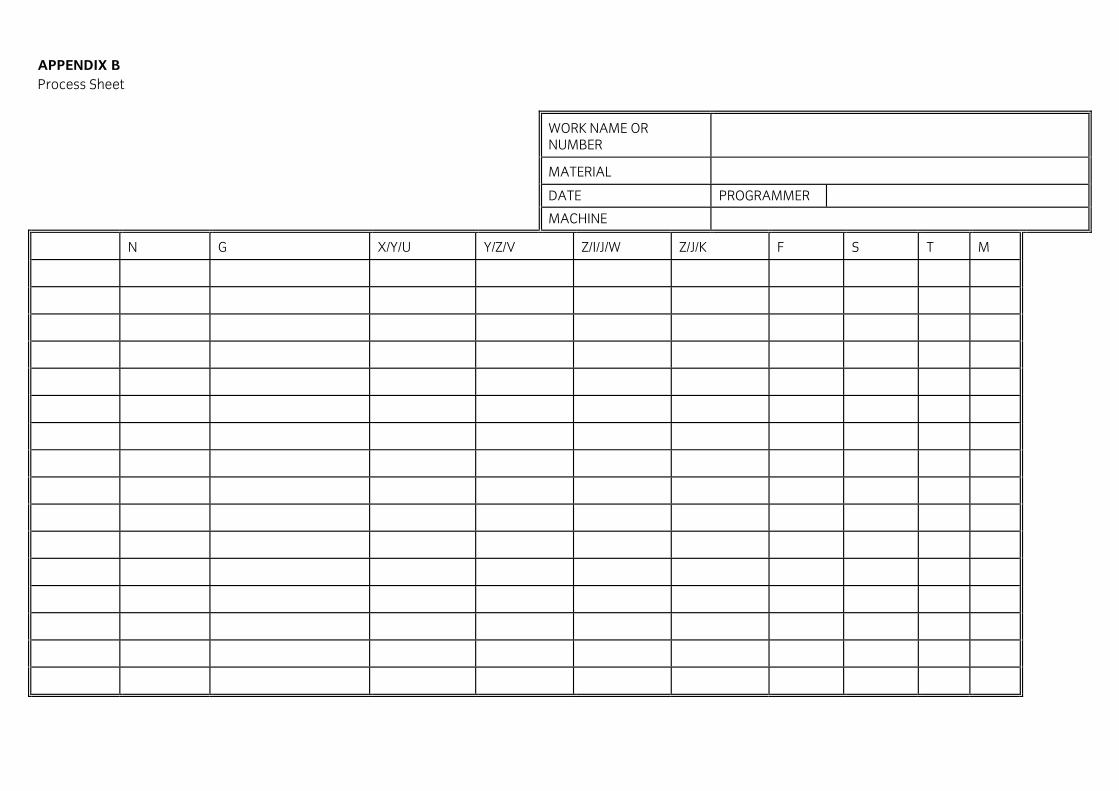
A summary of the codes to be used in programming practical work is given in Appendix C.
For assessments relating to element 2, candidates should be provided with an appropriate drawing.
For assessments relating to element 4, candidates should be provided with appropriate planning and process sheets.
Annexed to the Appendices is a range of speciman assignments for centres to use as guidance.

Part 1 – Computer-aided Engineering Unit 1 - Basic CNC
Element 1 Operating machine tools To provide evidence of competence in machine tool operation, the candidate must Practical tasks 001 perform machining operations on a simple component Knowledge criteria 002 describe common types of work holding methods 003 identify rake and clearance angles of cutting tools 004 describe applications of feeds, speeds and depth of cut. Assessment requirements for machine tool operation In practical tasks, on at least two occasions, candidates must prove ability to
Assessed ability Evidence required
1.1 Perform machining operations on a simple component.
1.1.1 Component correctly located and secured in suitable work holding device. 1.1.2 Spindle speed, work/tool travel rate and depth of cut set appropriate to material to produce smooth cut with good chip formation. 1.1.3 Tool set and clamped to produce smooth cut and good chip formation. 1.1.4 Finished components meets specification. 1.1.5 Safe working practice observed at all times.
In addition, to demonstrate an understanding of machine tools in general, candidates must prove ability to 1.2 Describe common types of work holding methods
a. identify standard methods for work holding for a pillar drill i. T-bolt and clamp ii. vice clamped to table
b. identify standard methods of work holding for a lathe i. 3-jaw chuck ii. 4-jaw chuck iii. face plate and clamps iv. between centres
c. identify common work holding methods for a milling machine i. T-bolts, clamps and work stops ii. vice clamped to table iii. indexing head clamped to table
d. state good and bad work holding applications i. unsupported clamping ii. low contact area iii. two line contact on round stock iv. need for positive end stop in milling v. hard clamping on finished surfaces
e. state the hazard associated with CNC machines with respect to work holding devices and which requires special programming attention

19
i. the need to ensure that, on a CNC machine, care is taken ii. that the tool path does not clash with the work holding device.
1.3 Identify rake and clearance angles on cutting tools used for
a. drilling b. turning c. milling.
1.4 Describe applications of feeds, speeds and depth of cut
a. convert surface metre per minute cutting speed to rpm of workpiece on a lathe using calculator and formula
b. convert surface metre per minute cutting speed to rpm on a milling cutter using calculator and formula c. convert feed rate from metres/minute, on a lathe, to mm/revolution using calculator and formula d. convert feed rate from mm/tooth, for a multi-tooth milling cutter, to metres/minute using calculator and
formula e. state, for tools with differing rake angles and applied cutting speeds, which would be used for
i. mild steel ii. aluminium
f. identify cutting speed and feed rate in an operations sheet.
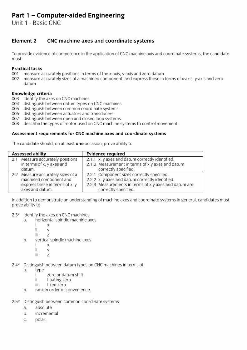
Part 1 – Computer-aided Engineering Unit 1 - Basic CNC
Element 2 CNC machine axes and coordinate systems To provide evidence of competence in the application of CNC machine axis and coordinate systems, the candidate must Practical tasks 001 measure accurately positions in terms of the x-axis, y-axis and zero datum 002 measure accurately sizes of a machined component, and express these in terms of x-axis, y-axis and zero datum Knowledge criteria 003 identify the axes on CNC machines 004 distinguish between datum types on CNC machines 005 distinguish between common coordinate systems 006 distinguish between actuators and transducers 007 distinguish between open and closed loop systems 008 describe the types of motor used on CNC machine systems to control movement. Assessment requirements for CNC machine axes and coordinate systems The candidate should, on at least one occasion, prove ability to Assessed ability Evidence required 2.1 Measure accurately positions
in terms of x, y axes and datum.
2.1.1 x, y axes and datum correctly identified. 2.1.2 Measurement in terms of x,y axes and datum correctly specified.
2.2 Measure accurately sizes of a machined component and express these in terms of x, y axes and datum.
2.2.1 Component sizes correctly specified. 2.2.2 x, y axes and datum correctly identified. 2.2.3 Measurements in terms of x,y axes and datum are correctly specified.
In addition to demonstrate an understanding of machine axes and coordinate systems in general, candidates must prove ability to 2.3* Identify the axes on CNC machines
a. horizontal spindle machine axes i. x ii. y iii. z
b. vertical spindle machine axes i. x ii. y iii. z.
2.4* Distinguish between datum types on CNC machines in terms of
a. type i. zero or datum shift ii. floating zero iii. fixed zero
b. rank in order of convenience. 2.5* Distinguish between common coordinate systems
a. absolute b. incremental c. polar.

21
2.6 Distinguish between actuators and transducers in terms of a. their function within a CNC machine b. typical examples
i. actuator - pneumatic/hydraulic cylinder, electric motor, lead screw, rack and pinion ii. transducer - rotary or linear optical resolvers.
2.7 Distinguish between open and closed loop systems in terms of
a. the use of actuators and transducers within the system b. typical examples.
2.8 Describe the types of motor used on CNC machine systems to control movement
a. name the type of motor used in an open loop system to control movement along a machine axis and state its major characteristic i. stepper motor rotates in a predictable way to pulse signals used for accurate position control
without the necessity of feedback b. name a type of motor used in closed loop control systems for positional control of a machine saddle
along its axis i. servomotor (ac or dc) needs feedback on velocity and position.
Part 1 – Computer-aided Engineering Unit 1 - Basic CNC
Element 3 Modifying part programs To provide evidence of competence in modifying part programs, the candidate must Practical tasks 001 modify a simple part program 002 prove and edit a simple part program Knowledge criteria 003 state the basic types of format used for NC programming 004 outline the function of common machine codes 005 state the objectives of part program verification 006 state the stages of part program verification 007 state some substitutional materials which can be used in part program verification and the advantages of using
them. Assessment requirements for modifying part programs The candidate should, on at least ONE occasion, modify and prove part program codes for one of the dimensions and the related speed of cut to change form or size or speed, and thus prove ability to
Assessed ability Evidence required
3.1 Modify a simple part program. 3.1.1 Located instructional block(s) in part program relevant to change(s), marked in new code(s)/instruction(s) correctly. 3.1.2 Loaded part program and edited to implement change(s). 3.1.3 Proved program by the method specified. 3.1.4 Ran program in single step mode and checked component to specification.
3.2 Prove and edit a simple part program.
3.2.1 Proved part program for errors by inspection using component drawing and process sheet. 3.2.2 Loaded part program, edited to enter corrections and had work checked by tutor. 3.2.3 Ran program in single step mode and checked component to specification.
In addition to demonstrate an understanding of part programming in general, candidates must prove ability to 3.3* State the basic types of format used for NC programming
a. fixed sequential b. word address.
3.4 Outline the function of common machine codes
a. convert codes to machine operations descriptions b. convert simple instructions into machine codes c. identify block in a line of a part program
i. that direct actuators in an axis ii. form the machine spindle on/off codes.

23
3.5* State the objectives of part program verification a. ensure safety b. avoidance of damage to tools and machinery c. assessment of opportunities to reduce cycle time.
3.6* State the stages of part program verification
a. work colleague to check b. run program in simulation mode c. run program on m/c in single step mode d. run program on machine with tools using substitutional material.
3.7* State some substitutional materials which can be used in part program verification and the advantages of using
them a. plastic/wax b. wood c. soft metal alloys.
APPENDIX A Planning Sheet
WORK NAME OR NUMBER
MATERIAL
DATE PLANNER
OPERATION TOOL OFF CUTTING SPEED
SPINDLE SPEED
FEEDRATE
No. SET /min rev/min /rev /min
APPENDIX B Process Sheet
WORK NAME OR NUMBER
MATERIAL
DATE PROGRAMMER
MACHINE
N G X/Y/U Y/Z/V Z/I/J/W Z/J/K F S T M
APPENDIX C SUMMARY OF THE CODES IN USE The codes in use during this course are given below. Note that some codes do the same thing. These codes are intended to be compatible with C&G 230-4-41/42. When the computer simulation of a CNC machine is set up, some of the modal codes are already in effect. Those codes are indicated here by an asterisk (*).
G00 Rapid traverse to position X, Z
G01 Linear feed to position X,Z
G02 Clockwise circular interpolation at feedrate
G03 Anti-clockwise circular interpolation at feedrate
G04 Dwell (with code letter X for time of dwell
G20 Diameter programming
G21* Radius programming
G33 Thread cutting cycle
G40* Cancel tool nose radius compensation
G41 Tool nose radius compensation left
G42 Tool nose radius compensation right
G50 Define datum point (axis pre-set)
G70 All dimensions are in inches
G71* All dimensions are in millimetres
G74 Turning cycle
G75 Facing cycle
G76 Multi-pass thread cutting cycle
G80* Cancel canned cycles
G90* All X and Y dimensions are absolute
G91 All X and Z dimensions are incremental or relative
G92 Define datum point (axis pre-set)
G94 Feed in inches or millimetres per minute
G95 Feed in inches or millimetres per revolution
G96 Constant surface speed
G97 Revolutions per minute
M00 Program stop
M01 Optional program stop
M02 Machine and program stop
M03 Spindle on forward
M04 Spindle on in reverse
M05* Spindle off
M07 Coolant on
M08 Coolant on
M09* Coolant off
M30 Machine and program stop and tape rewind

The other codes follow. For this unit, most of these codes can take any decimal number, for example, 1234.5678, or a number with no decimal point, which will be divided by 1000 to make it equivalent to a number with a decimal point. Form example, if we type in X40, then the computer will read this as X0.04 and if we had actually meant to type in X40,m then we would be in for a surprise. Codes which take any decimal number are marked `f' for free format. Those codes with a fixed format are indicated.
Af Angle for G76 cycle
Df Radius step for G76 cycle
Ef Feed rate for thread cutting
Ff Feed rate
If Arc centre X coordinate or supplementary X value
Kf Arc centre Z coordinate or supplementary Z value
N Line number, N must be followed by four digits
Sf Spindle speed or constant surface speed
T Tool selection, T may be followed by either two or four digits
Uf Incremental X value
Wf Incremental Z value
Xf Distance across lathe axis
Zf Distance across lathe axis
Part 1 – Computer-aided Engineering Unit 2 - Basic CAD
Introduction This unit is intended to provide a practical introduction to CAD applications. It thus forms a foundation for the related Part 2 schemes. Participants should have acquired competences equivalent to those assessed in the common units in Computing and Digital Electronics, either by successful study in this unit or by other means. In this unit, the CAD software and equipment used may vary from one centre to another. To maintain integrity however, the CAD system involved will be registered as part of the approval for the course. This unit does not aim at general mastery in this field of work, but the assessment will be criterion-referenced and will concern mainly practical performances. The range and level of assessment will provide a basic standard for entry to Part 2 CAD and will complement the fundamental concepts involved in Computer-aided Engineering as a whole.
Guidance notes on Basic CAD Course notes a. The unit does not assume any previous experience of CAD nor do the course objectives necessarily require the
use of industrial CAD systems, but it does require that the equipment and procedures used are approved by the course assessors.
b. By limiting the performance objectives to the machinery, equipment, procedures and products approved for
the course, it is then feasible to take the learning through to full, hands-on practical operation. It is here that the compulsory, criterion-based assessments will be made.
c. Where consideration of the more general aspects is materially helpful (or necessary) to the formation and
comprehension of key concepts, these and other enabling aspects will be included in the learning and subject to graded forms of assessment.
Practical assessment notes Because of the variance in command procedures in different CAD systems which may be employed in this unit each centre will need to produce appropriate menu/command lists for use with Element 2.
Part 1 – Computer-aided Engineering Unit 2 - Basic CAD
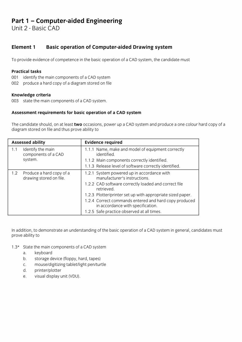
Element 1 Basic operation of Computer-aided Drawing system To provide evidence of competence in the basic operation of a CAD system, the candidate must Practical tasks 001 identify the main components of a CAD system 002 produce a hard copy of a diagram stored on file Knowledge criteria 003 state the main components of a CAD system. Assessment requirements for basic operation of a CAD system The candidate should, on at least two occasions, power up a CAD system and produce a one colour hard copy of a diagram stored on file and thus prove ability to
Assessed ability Evidence required
1.1 Identify the main components of a CAD system.
1.1.1 Name, make and model of equipment correctly identified. 1.1.2 Main components correctly identified. 1.1.3 Release level of software correctly identified.
1.2 Produce a hard copy of a drawing stored on file.
1.2.1 System powered up in accordance with manufacturer's instructions. 1.2.2 CAD software correctly loaded and correct file retrieved. 1.2.3 Plotter/printer set up with appropriate sized paper. 1.2.4 Correct commands entered and hard copy produced in accordance with specification. 1.2.5 Safe practice observed at all times.
In addition, to demonstrate an understanding of the basic operation of a CAD system in general, candidates must prove ability to 1.3* State the main components of a CAD system
a. keyboard b. storage device (floppy, hard, tapes) c. mouse/digitizing tablet/light pen/turtle d. printer/plotter e. visual display unit (VDU).

Part 1 – Computer-aided Engineering Unit 2 - Basic CAD
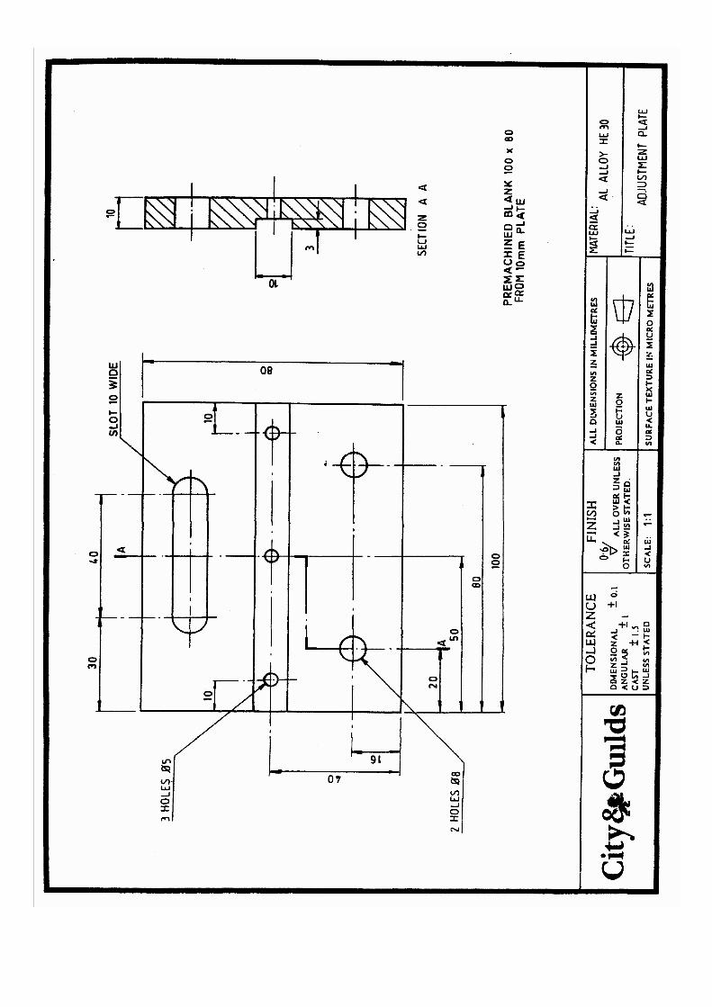
Element 2 Produce two-dimensional drawings on a Computer-aided Drawing system To provide evidence of competence in producing 2D drawings on a CAD system, the candidate must Practical tasks 001 produce 2D drawings to a given specification Knowledge criteria 002 state the procedures used for main drawing commands 003 describe the procedure to be used when scaling. Assessment requirements for producing 2D drawings on a CAD system The candidate should, on at least two occasions, carry out the following tasks a. produce a 2D drawing involving plan, side and front elevations of a rectangular item with a simple, milled
channel of regular shape and apply fillets or chamfers to the 4 edges of the rectangle, set in mm units and suitable for 1:2 scale representation at A4 drawing size; apply dimensions to overall size only; the channel to be half the depth of the item thickness; save and plot/print the final drawing.
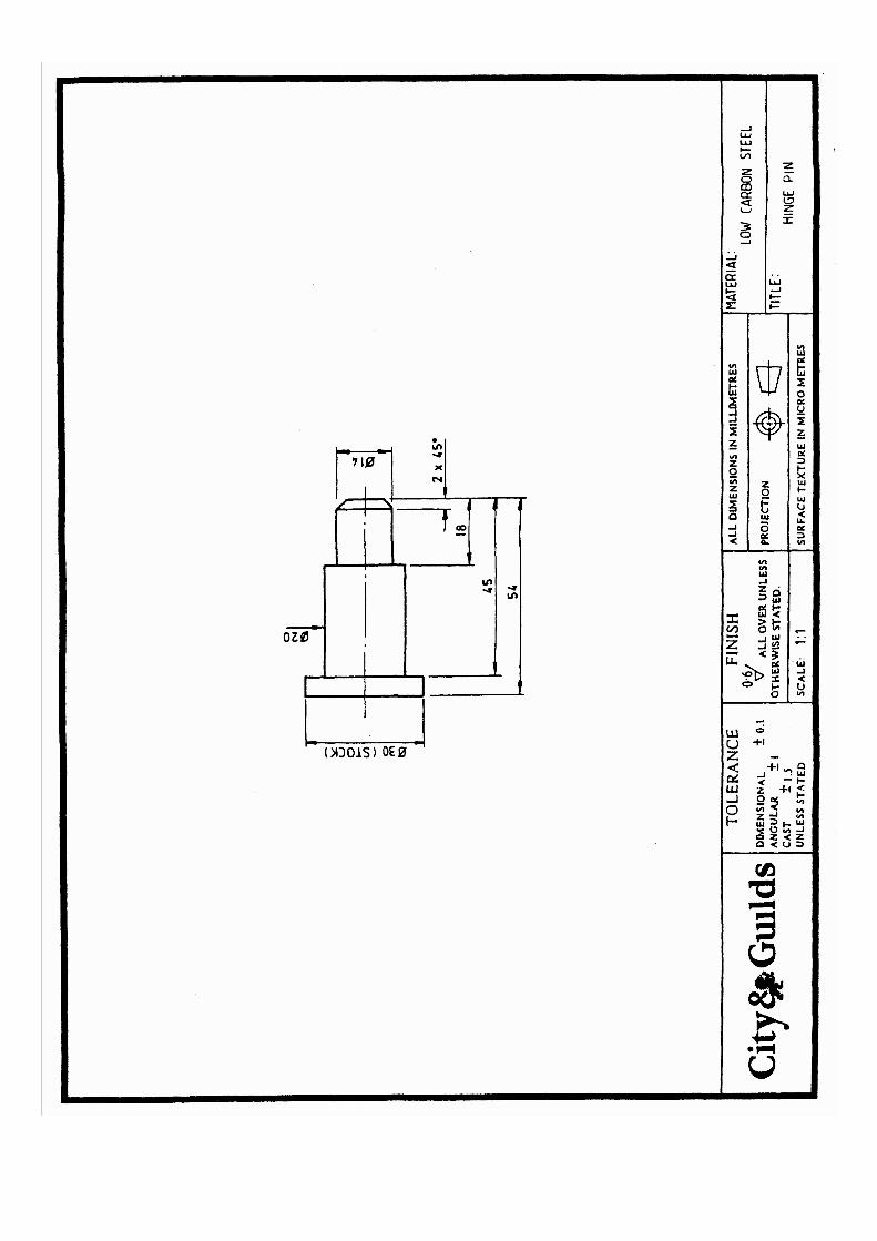
b. produce a 2D drawing involving side and front elevations of a circular, flanged component with 6 counter-
bored holes equally disposed around the flange, the body to have 2 further diameters and a central bore, indicated corners broken with chamfers, the system to be set in mm units and suitable for 1:2 scale representation on A4 drawing size, apply dimensions, in a separate layer, to all drawing features. Save to a new file name, plot/print the new drawing.
and thus prove ability to
Assessed ability Evidence required
2.1Produce 2D drawings to a given specification.
2.1.1 Correct procedure used to open system for a new drawing. 2.1.2 Set correct parameters for scale and output drawing size. 2.1.3 Drawing produced to BS308 including dimensioning. 2.1.4 All required dimensions applied with correct and neat format; dimensions on separate layer. 2.1.5 Plotter/printer set up with appropriate sized paper. 2.1.6 Final drawing met specification and print/plot satisfactory. 2.1.7 Appropriate commands used to save drawing.
In addition, to demonstrate an understanding of 2D drawing on a CAD system in general, candidates must prove ability to

2.2* State the procedures used for main menu drawing commands a. draw a circle b. dimension a circle c. set and draw centre lines d. make and name a new layer e. draw fillets or chamfers f. find the coordinates for a point feature from a given zero datum feature for a fully dimensioned drawn
item g. set up for using the array (or copy-repeat) feature h. print/plot a drawing.
2.3 Describe the procedure to be used when scaling in terms of
a. establishing simple drawing scales (ratios) to suit a rectangle drawn landscape on A4 paper (197mm x 210mm), giving only a plan view
b. plotting, printing approximately true to a given scale on A4 paper and a zero datum at the bottom/left of the screen
c. the use of the snap facility to give precise dimensioning of a rectangular length.
Part 1 – Computer-aided Engineering Unit 3 - Basic Robotics
Introduction This unit is intended to provide a practical introduction to Robotics -robotic manipulators and their operation. It thus forms a foundation for the related Part 2 scheme in this subject area. Participants should have acquired competences equivalent to those assessed in the common units in Computing and Digital Electronics, either by successful study in this unit or by other means. In this unit, the robotic devices and other ancillary equipment used may vary from one centre to another. To maintain integrity however, the hardware and procedures involved will be registered as part of the approval for the course. This unit does not aim at general mastery in this field of work, but the assessment of the main objectives related to specific course machinery, equipment and procedures will be criterion-referenced and will concern mainly practical performances.
Guidance notes on robotics Course notes a. The unit does not assume any previous experience of Robots nor do the course objectives necessarily require
the use of industrial scale units and related equipment, but it does require that the equipment and procedures used are approved by the course assessors.
b. By limiting the performance objectives to the machinery, equipment and procedures approved for the course,
it is then feasible to take the learning through to full, hands-on practical operation. It is here that the compulsory, criterion-based assessments will be made.
c. Where consideration of the more general aspects is materially helpful (or necessary) to the formation and
comprehension of key concepts, these and other enabling aspects will be included in the learning and subject to graded forms of assessment.
d. The treatment of the potential hazards associated with robots and the precautions for minimising them should
be a prominent and continuous feature of the scheme.
Part 1 – Computer-aided Engineering Unit 3 - Basic Robotics
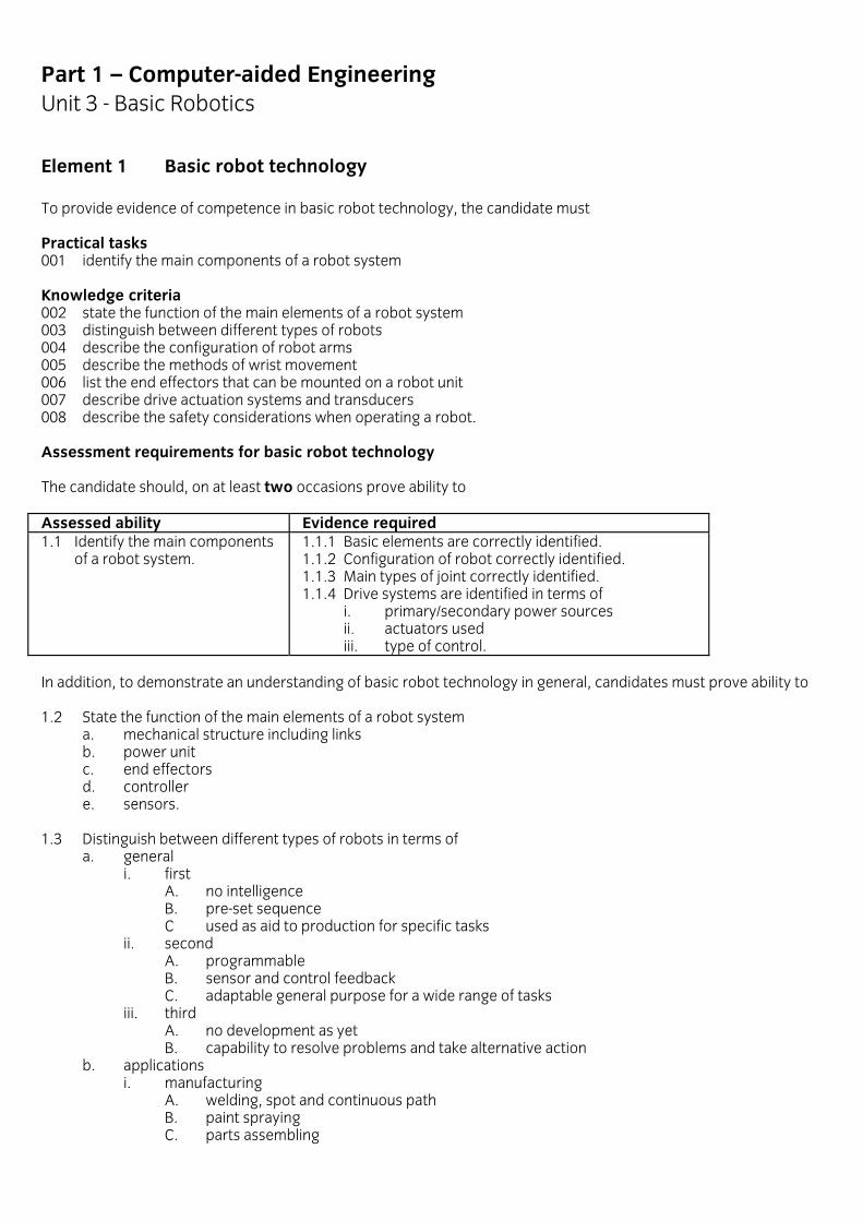
Element 1 Basic robot technology To provide evidence of competence in basic robot technology, the candidate must Practical tasks 001 identify the main components of a robot system Knowledge criteria 002 state the function of the main elements of a robot system 003 distinguish between different types of robots 004 describe the configuration of robot arms 005 describe the methods of wrist movement 006 list the end effectors that can be mounted on a robot unit 007 describe drive actuation systems and transducers 008 describe the safety considerations when operating a robot. Assessment requirements for basic robot technology The candidate should, on at least two occasions prove ability to Assessed ability Evidence required 1.1 Identify the main components of a robot system.
1.1.1 Basic elements are correctly identified. 1.1.2 Configuration of robot correctly identified. 1.1.3 Main types of joint correctly identified. 1.1.4 Drive systems are identified in terms of i. primary/secondary power sources ii. actuators used iii. type of control.
In addition, to demonstrate an understanding of basic robot technology in general, candidates must prove ability to 1.2 State the function of the main elements of a robot system
a. mechanical structure including links b. power unit c. end effectors d. controller e. sensors.
1.3 Distinguish between different types of robots in terms of
a. general i. first
A. no intelligence B. pre-set sequence C used as aid to production for specific tasks ii. second A. programmable B. sensor and control feedback C. adaptable general purpose for a wide range of tasks iii. third A. no development as yet B. capability to resolve problems and take alternative action b. applications i. manufacturing A. welding, spot and continuous path B. paint spraying C. parts assembling

ii. handling A. pick and place B. load and unload C. packing iii. testing A. autotest or inspection B. used in hazardous conditions. 1.4 Describe the configuration of robot arms in terms of the a. main types of motion (joint)
i. revolute (rotary) ii. prismatic (linear)
b. main standard classes of configuration i. cartesian ii. polar-cylindrical iii. polar-spherical iv. articulated (anthropometric)
c. concept of working envelope. 1.5* Describe the methods of wrist movement in terms of a. pitch b. roll c. yaw for specific joint movements. 1.6* List the end effectors that can be mounted on a robot unit
a. gripping devices/hooks/scoops and ladles b. magnetic pickups/vacuum cups c. welding heads d. spraying heads e. drilling/routing/grinding heads f. fasteners.
1.7* Describe drive actuation systems and transducers in terms of
a. the role of actuator and transducer, giving an example of an actuator that does not necessarily need a transducer for position control
b. definition of the role of feedback in a closed loop control system c. transducer types which provide digital information direct and those which require analogue to digital
modules d. the relative advantage of hydraulic, pneumatic and electric motor drive actuators as applied to
linear(prismatic) type joints and rotary (revolute) joints e. relative and absolute angular position control transducers and the difference this makes to the control
system. 1.8* Describe the safety considerations when operating a robot in terms of
a. use of failsafe circuits b. safe working practices of operator and maintenance personnel c. adequate guarding.

Part 1 – Computer-aided Engineering Unit 3 - Basic Robotics
Element 2 Programming a robot To provide evidence of competence in programming a robot, the candidate must Practical tasks 001 program a robot to perform simple tasks 002 modify a robot program Knowledge criteria 003 compare lead through, step mode and off-line programming methods 004 describe basic robot operation techniques 005 describe basic robot programming techniques. Assessment requirements for programming a robot The candidate should, on at least one occasion, carry out the following programming tasks a. use a lead through/teach mode to program a robot to achieve a pick and place task and return to park/home
position and repeat b. use a step mode to program a robot to achieve a pick and place task, following shortest route, and return to
park position and repeat c. carry out an off-line program edit of the program from b) to avoid an obstacle to the shortest route and meet a
given accuracy of placement to prove ability to
Assessed ability Evidence required
2.1 Program a robot to perform simple tasks.
2.1.1 Correct safety and procedure to power up, load master program and enter through program mode. 2.1.2 Part position entered in first step, suitable step positions located, coordinates entered together with grip, move, place and release commands and jump at end. 2.1.3 Robot carries out task to specification and in a safe and efficient manner.
2.2 Modify a robot program. 2.2.1 Correct procedure used to load the program and to enter mode for off-line edit. 2.2.2 Program listing annotated for suitable changes with added step lines for re-routing and for introduction of wait function (if not in earlier program) at pick and place steps. 2.2.3 Correct procedures used to introduce space for extra lines and new steps and functions added, program proved in step mode, saved, listed and run in single cycle.
In addition, to demonstrate an understanding of programming a robot in general, candidates must prove ability to 2.3* Compare lead through, step mode and off-line programming methods in terms of

a. entering the programming b. key presses required c. programming "blind".
2.4* Describe basic robot operation techniques in terms of
a. halting and restarting a program that is running b. cleaning memory prior to entering a program.
2.5* Describe basic robot programming techniques in terms of
a. entering park position into a program b. increasing accuracy of pick and place action.

Part 1 – Computer-aided Engineering Unit 4 – Basic PLC
Introduction This unit is intended to provide a practical introduction to PLC operation and programming. It thus forms a foundation for the related Part 2 scheme. Participants should have acquired competences equivalent to those assessed in the common units in Computing and Digital Electronics, either by successful study in this unit or by other means. Participants will undertake practical tasks to introduce them to simple PLC applications and programming. In this unit, the PLC equipment used may vary from one centre to another. This unit does not aim at general mastery in this field of work, but the assessment of the main objectives related to specific course machinery, equipment and procedures will be criterion-referenced and will concern mainly practical performances. Guidance notes on PLC operation and programming Course notes a. The unit does not assume any previous experience of PLCS nor do the course objectives necessarily require the
use of industrial PLC units, but it does require that the equipment and procedures used are approved by the course assessors.
b. By limiting the performance objectives to the equipment and procedures approved for the course, it is then
feasible to take the learning through to full, hands-on practical operation. It is here that the compulsory, criterion-based assessments will be made.
c. Where consideration of the more general aspects is materially helpful (or necessary) to the formation and
comprehension of key concepts, these and other enabling aspects will be included in the learning and subject to graded forms of assessment.
d. The treatment of the potential hazards associated with PLCS and the precautions for minimising them should
be a prominent and continuous feature of the scheme. e. Input and output modules or interfaces
To condition the varying electrical characteristics of its inputs and outputs and match the TTL levels within the PLC, a range of input and output plug-in modules have to be provided.
f. These interface units include, in their duties, various combinations; resistors or transformers to divide or step
down voltages, bridge rectifiers to convert from ac to dc, ADCs to convert analogue input values to digital form or DACs for the reverse process in some outputs, additional memory to store the results of high speed counters.
g. Input-output isolation from plc
Voltage and current levels in the external field wiring can be very much higher than the TTL voltages used within the PLC. In some cases, the PLC may be protected from external events by triggering inputs and outputs through opto-isolators, which effectively isolate the PLC from the field circuits.

Part 1 – Computer-aided Engineering Unit 4 – Basic PLC
Assessment It is required that approved centres will have produced and presented model PLC setups for assessment criteria. It is required that approved centres will have Typical input devices Start and Stop switches, limit switches, reed switches, thumb wheel and other options elect switches; temperature, various light/optical detector, pressure, speed, level and sensing switches; various angular and linear position encoders; up and down counters These input devices can be associated with many different electrical characteristics; 110-240 volts ac, 12-240 volts dc; on/off and other digital type signals versus analogue signal values, often offering very small current levels, such as thermocouples, reed switches. Typical output devices Electro-mechanical relays controlling motors and other drive or switching circuits, solenoids and solenoid valves in hydraulic systems, stepper motor/indexer, switches for alarm and indicator lights, small servo-motors and servo-valve positioners These output devices can be associated with many different electrical loads and characteristics; single and multi-phase supplies, high and low voltages sometimes with high current load, on-off and other digital type signals versus analogue form of signals. Example 1 Given Boolean statements for required input/outputs, complete a corresponding ladder diagram to drive 3 indicator lamps using 3 push button input switches, such that only one lamp may be driven at a time, enter this into a PLC and prove out the program. Example 2 Compile Boolean statements from a truth table, use these to edit a ladder diagram to drive 4 lamps through 2 single pole switches, such that the circuit and switch functiond reproduce the requirements specified in the given truth table, enter this into a PLC and prove out a program.

Part 1 – Computer-aided Engineering Unit 4 – Basic PLC
Element 1 PLC systems technology To provide evidence of competence in PLC system technology, the candidate must Knowledge criteria 001 describe the functions of the main components of a PLC system 002 describe the structure of a PLC memory 003 compare electro-mechanical forms of switching with PLC software forms 004 describe PLC input and output devices. 005 describe the basic principles of digital logic. Assessment requirements for basic PLC systems technology In addition to demonstrate an understanding of PLC system technology in general, candidates must prove ability to 1.1* Describe the functions of the main components of a PLC system
a. control unit b. programming device c. input/output modules
1.2 Describe the structure of a PLC memory in terms of
a. the main sections of a PLC memory i. user (logic) memory ii. input (register or memory) iii. output (register or memory)
b. location nominated memory addresses on a memory grid map. 1.3* Compare electro-mechanical forms of switching with PLC software forms in terms of
a. function b. reliability c. flexibility for circuit changes
1.4 Describe PLC input and output devices in terms of
a. classification of devices as input or outputs b. the role of input and output modules or interfaces
i. matching input/output signal levels to TTL levels ii. converting analogue to digital signals and vice versa
c. where there is need for an output to be exercised through a relay or other output module i. where the field device demands high voltage ii. where the field device demands high current iii. where multi-phase supply is involved iv. where a stepper motor indexer is required v. where an analogue value has to be transmitted such as for a servo-valve positioner.

1.5 Describe the basic principles of digital logic a. identify AND, OR and NOT symbols b. draw up a truth table for each of the gates listed in (a) c. construct rungs in a ladder diagram to illustrate AND, OR and NOT as input conditions in the control of an
output, given a simple truth table and a 2 rung diagram.

Part 1 – Computer-aided Engineering Unit 4 – Basic PLC
Element 2 PLC operation and programming To provide evidence of competence in PLC operation and programming, the candidate must Practical tasks 001 set up a PLC 002 modify a PLC program Assessment requirements for PLC operation and programming The candidate should, on at least two occasions prove ability to
Assessed ability Evidence required
2.1 Set up a PLC. 2.1.1 Correct procedure to power up and enter program mode and file loaded for edit 2.1.2 instruction interpreted correctly: ladder rung identified and located, modification made and file saved
2.2 Modify a PLC program to a given specification.
2.2.1 Boolean statements and ladder diagram produced to meet new requirements. 2.2.2 Program correctly modified to meet new specification. 2.2.3 program run and proved to obtain the requested result. 2.2.4 Safe working practice followed at all times.
Part 1 Unit 5 - Basic Computer Skills
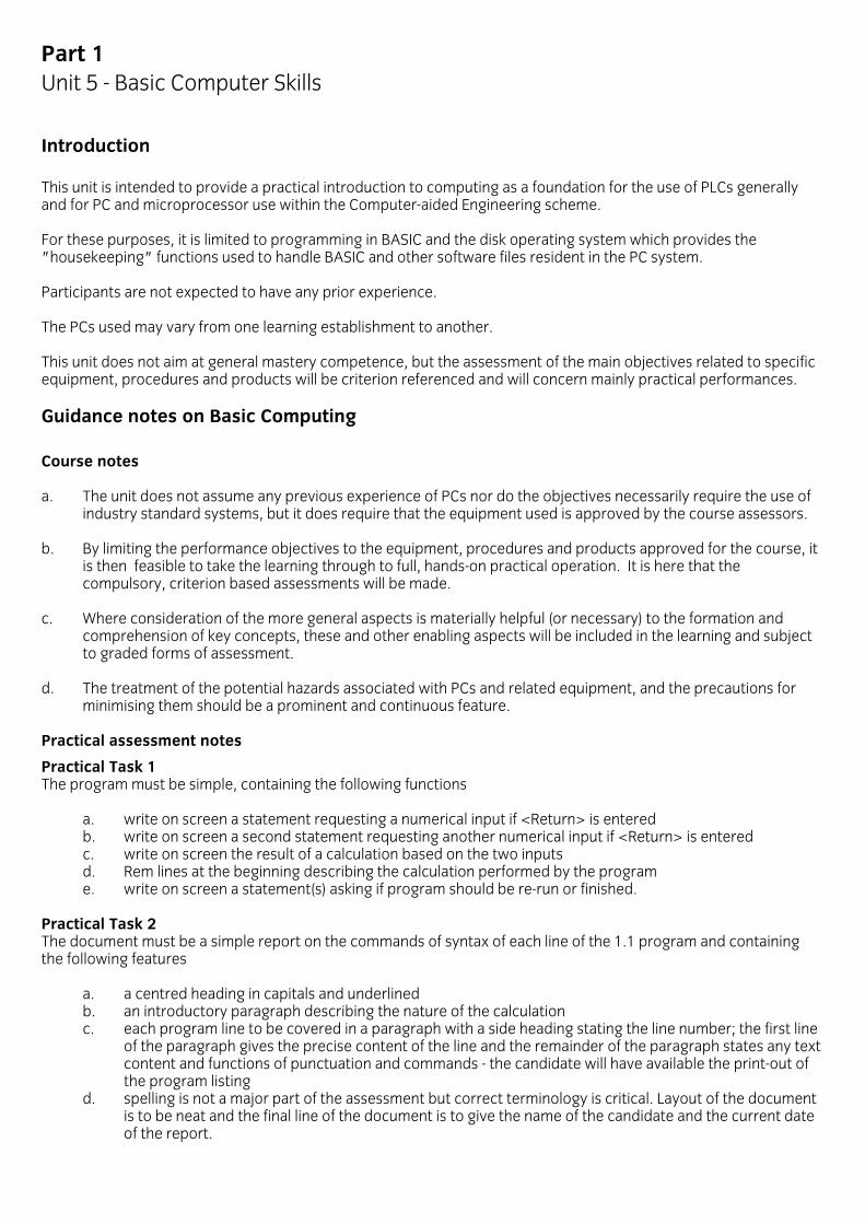
Introduction This unit is intended to provide a practical introduction to computing as a foundation for the use of PLCs generally and for PC and microprocessor use within the Computer-aided Engineering scheme. For these purposes, it is limited to programming in BASIC and the disk operating system which provides the "housekeeping" functions used to handle BASIC and other software files resident in the PC system. Participants are not expected to have any prior experience. The PCs used may vary from one learning establishment to another. This unit does not aim at general mastery competence, but the assessment of the main objectives related to specific equipment, procedures and products will be criterion referenced and will concern mainly practical performances.
Guidance notes on Basic Computing Course notes a. The unit does not assume any previous experience of PCs nor do the objectives necessarily require the use of
industry standard systems, but it does require that the equipment used is approved by the course assessors. b. By limiting the performance objectives to the equipment, procedures and products approved for the course, it
is then feasible to take the learning through to full, hands-on practical operation. It is here that the compulsory, criterion based assessments will be made.
c. Where consideration of the more general aspects is materially helpful (or necessary) to the formation and
comprehension of key concepts, these and other enabling aspects will be included in the learning and subject to graded forms of assessment.
d. The treatment of the potential hazards associated with PCs and related equipment, and the precautions for
minimising them should be a prominent and continuous feature. Practical assessment notes
Practical Task 1 The program must be simple, containing the following functions
a. write on screen a statement requesting a numerical input if <Return> is entered b. write on screen a second statement requesting another numerical input if <Return> is entered c. write on screen the result of a calculation based on the two inputs d. Rem lines at the beginning describing the calculation performed by the program e. write on screen a statement(s) asking if program should be re-run or finished.
Practical Task 2 The document must be a simple report on the commands of syntax of each line of the 1.1 program and containing the following features
a. a centred heading in capitals and underlined b. an introductory paragraph describing the nature of the calculation c. each program line to be covered in a paragraph with a side heading stating the line number; the first line
of the paragraph gives the precise content of the line and the remainder of the paragraph states any text content and functions of punctuation and commands - the candidate will have available the print-out of the program listing
d. spelling is not a major part of the assessment but correct terminology is critical. Layout of the document is to be neat and the final line of the document is to give the name of the candidate and the current date of the report.
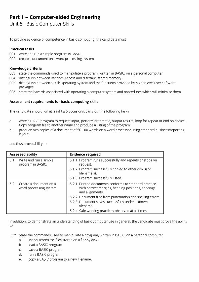
Part 1 – Computer-aided Engineering Unit 5 - Basic Computer Skills To provide evidence of competence in basic computing, the candidate must Practical tasks 001 write and run a simple program in BASIC 002 create a document on a word processing system Knowledge criteria 003 state the commands used to manipulate a program, written in BASIC, on a personal computer 004 distinguish between Random Access and disk/tape stored memory 005 distinguish between a Disk Operating System and the functions provided by higher level user software packages 006 state the hazards associated with operating a computer system and procedures which will minimise them. Assessment requirements for basic computing skills The candidate should, on at least two occasions, carry out the following tasks a. write a BASIC program to request input, perform arithmetic, output results, loop for repeat or end on choice.
Copy program file to another name and produce a listing of the program b. produce two copies of a document of 50-100 words on a word processor using standard business/reporting
layout and thus prove ability to
Assessed ability Evidence required
5.1 Write and run a simple program in BASIC.
5.1.1 Program runs successfully and repeats or stops on request. 5.1.2 Program successfully copied to other disk(s) or filename(s). 5.1.3 Program successfully listed.
5.2 Create a document on a word processing system.
5.2.1 Printed documents conforms to standard practice with correct margins, heading positions, spacings and alignments. 5.2.2 Document free from punctuation and spelling errors. 5.2.3 Document saves successfully under a known filename. 5.2.4 Safe working practices observed at all times.
In addition, to demonstrate an understanding of basic computer use in general, the candidate must prove the ability to 5.3* State the commands used to manipulate a program, written in BASIC, on a personal computer
a. list on screen the files stored on a floppy disk b. load a BASIC program c. save a BASIC program d. run a BASIC program e. copy a BASIC program to a new filename.

5.4* Distinguish between Random Access and disk/tape stored memory in terms of
a. cost b. accessibility.
5.5* Distinguish between a Disk Operating System and the functions provided by higher level user software packages in terms of
a. functions available to i. DOS ii. higher-level languages.
5.6* State the hazards associated with operating a computer system and the precautions which will minimise them
a. eye strain b. fatigue
i. due to equipment ii. due to environment iii. due to posture.
Part 1 – Computer-aided Engineering Unit 6 - Basic Digital Electronics
Introduction This unit is intended to provide a practical introduction to digital electronics as a foundation for PC and microprocessor use within the Computer-Aided Engineering scheme. For these purposes, it is limited to an introduction to binary expressions of numbers, binary arithmetic, ASCII character codes and their decimal and binary representation, binary codes and the computer; binary digits and their application in logic gates, Boolean operations and truth tables, some memory address concepts and digital/analogue comparisons and conversion. Participants are not expected to have any prior experience. The equipment used may vary from one learning establishment to another. This unit does not aim at general mastery competence, but the assessment of the main objectives related to specific course equipment, procedures and products will be criterion referenced and will concern mainly practical performances.
Guidance notes on Basic Digital Electronics Course notes 1. The unit does not assume any previous experience of electronics nor do the objectives necessarily require the
use of industry standard systems, but it does require that the equipment used is approved by the course assessors.
2. By limiting the performance objectives to the equipment, procedures and products approved for the course, it
is then feasible to take the learning through to full, hands-on practical operation. It is here that the compulsory, criterion based assessments will be made.
3. Where consideration of the more general aspects is materially helpful (or necessary) to the formation and
comprehension of key concepts, these and other enabling aspects will be included in the learning and subject to graded forms of assessment.
4. The treatment of the potential hazards associated with electronics and related equipment, and the precautions
for minimising them should be a prominent and continuous feature. Practical assessment notes a. It is intended that the apparatus for practical tasks will be constructed by the training provider in four separate
forms for each combination of AND and OR units and that the circuit should have one of the two switched inputs as a common to both logic gates and the output from the first gate as the second input to the second gate.
b. The apparatus will include signal lamps at each input and output gate to signal the UP condition; this is
necessary to identify the logic of the first gate when one of the two is an AND and the other an OR, as this cannot be inferred from the final output condition because it is the same for both circuits.
c. Tutors should aim to provide practical tasks in working with Logic Gates and Truth Tables which test the
students' ability to specify the function of gates from their outputs in response to changes in inputs when in a simple logic circuit.
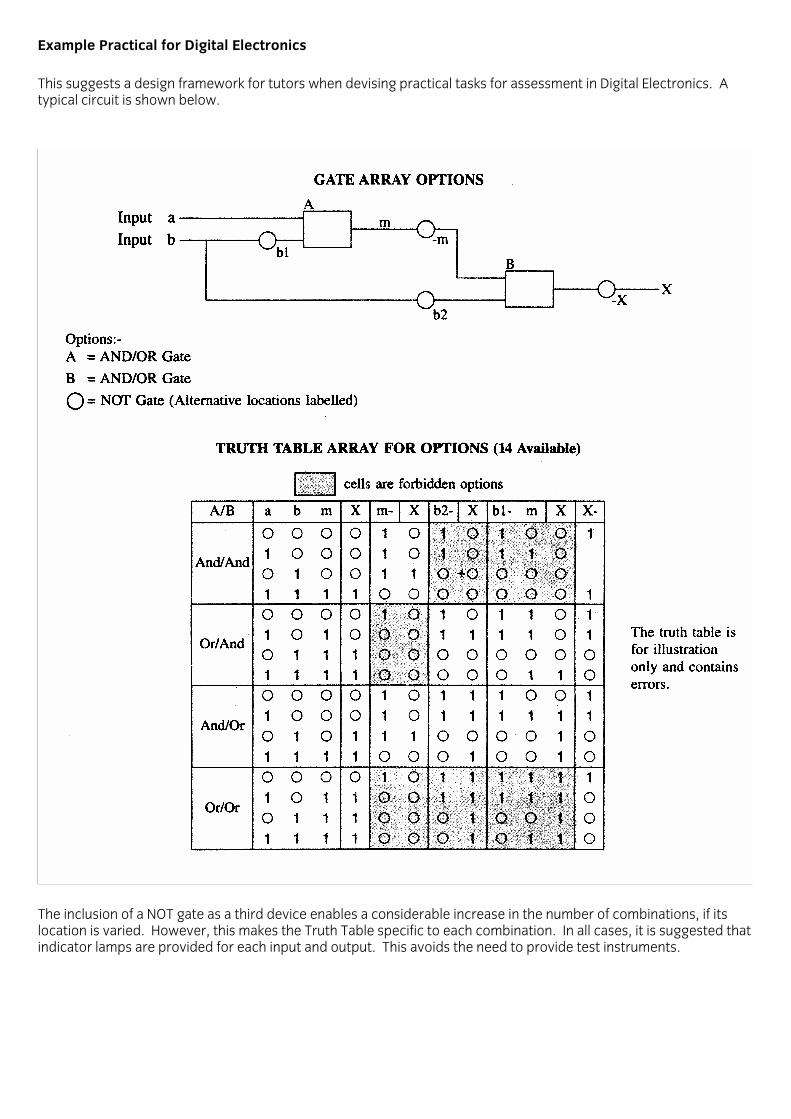
Example Practical for Digital Electronics This suggests a design framework for tutors when devising practical tasks for assessment in Digital Electronics. A typical circuit is shown below.
The inclusion of a NOT gate as a third device enables a considerable increase in the number of combinations, if its location is varied. However, this makes the Truth Table specific to each combination. In all cases, it is suggested that indicator lamps are provided for each input and output. This avoids the need to provide test instruments.

Part 1 – Computer-aided Engineering Unit 6 - Basic Digital Electronics To provide evidence of competence in basic digital electronics, the candidate must Practical tasks 001 analyse the signals from logic gates Knowledge criteria 002 perform operations using binary numbers 003 outline the principles of digital coding 004 describe the principles of digital logic 005 describe analogue and digital systems. Assessment requirements for basic digital electronics The candidate should, on at least two occasions, carry out the following tasks a. apply given signals to the input terminals of a set of logic gates, and combinations of gates, construct truth
tables and determine the function of each gate and combination. and thus prove ability to Assessed ability Evidence required 6.1 Analyse the signals from logic gates.
6.1.1 Inputs set correctly as per specification. 6.1.2 Truth table accurately completed and function of gate/combination correctly stated.
In addition, to demonstrate an understanding of basic digital electronics in general, the candidate must prove the ability to 6.2 Perform operations using binary numbers
a. convert decimal numbers, between 0-31, to binary form b. convert binary numbers of 5 digits to decimal values c. add 2 binary numbers of 4 digits (results should not exceed 5 digits).
6.3 Outline the principles of digital coding
a. define the terms i. bit ii. byte iii. word
b. relate bytes, kilobytes and megabytes c. identify the decimal and binary equivalents of alphanumeric characters d. state how a 4 bit binary word can be used to address a 16 location memory map of A0 to A15 e. write the address codes for the map stated in d).
6.4 Describe the principles of digital logic
a. identify the BS symbols for the logic gates i. AND ii. OR iii. NOT
b. compile truth tables for each of the gates in a) c. compile truth tables for combinations of up to three logic gates d. write Boolean statements of the logic states of 2 inputs for each of the outputs in a system, using truth
tables.

6.5 Describe analogue and digital systems a. classify quantities or values as analogue or digital
i. Analogue properties or values: temperature, weight, length, speed, volume, sound wave, sine wave, radio wave, telephone voice transmission
ii. Analogue devices: RC circuits - amplifiers, rectifiers, op-amps, telephone handset, galvanometer, wireless tuning knob, wireless volume control, petrol gauge float, conventional watch, needle compass, mercury thermometer; rheostat, lead screw, servo motor, record groove and playback head
iii. Digital properties or values: telephone number, binary number, decimal number; quantity of ball bearings, codification of alphanumeric characters for representation, manipulation and transmission of text and for the execution of complex calculations
iv. Digital devices: electric light switch, limit switch, telephone dialer, thermostat switch, keyboard, logic gates, car odometer, compact disc and player, stepping motor, electronic calculators, watches and clocks with numerical display, typewriters, PCs and PLCs
b. compare the advantages and disadvantages of analogue and digital systems in terms of i. versatility in manipulating and transmitting data ii. quality and integrity of processing data iii. cost of the system.

Level 2, 3 & 4 Certificate in Computer-aided Engineering Competences (2303)
Part 2 – Computer-aided Engineering
Version 1.0

Part 2 - NC/CNC Machine Setting and Operation
Introduction This scheme is intended to provide a knowledge of the techniques of setting and operating CNC machines. It is primarily concerned with the verification and use of part programs rather than the detailed techniques of part-programming. It is generally agreed that, while CNC replaces many hand skills, its effective use still depends on knowledge intrinsic to conventional machining. In general terms then, this scheme is intended for those who have already acquired (or will acquire concurrently) a sound understanding of machining technology.
Guidance Notes on NC/CNC Machine Setting and Operation Course notes a. The scheme does not assume previous study of CNC machining, and tutors will therefore need to take account
of the previous education, training, and experience of students when planning courses. The scheme does assume that students will have access to industrial scale CNC machinery.
b. The treatment of the potential hazards associated with CNC machines, and the precautions for minimising
them should be a prominent and continuous feature of the scheme. c. Students should be given a broad appreciation of the variety of applications of NC machines in their industry,
and the type of work produced. d. Students should be made aware that the control of the machine is not "intelligent". All operation details
therefore need to be specified. e. An awareness of following routine maintenance requirements should be included as a feature of practical
work, though it does not form part of the assessment. 1. Carry out daily/weekly lubrication that may be required 2. Check - air supply pressure
i. air filters ii. level of lubrication oil iii. filters iv. coolant supply v. swarf clearance
on pneumatic system. 3. Keep machine clean and tidy.

Part 2 - NC/CNC Machine Setting and Operation Unit 1 - Safety Procedures To provide evidence of competence in safety procedures, the candidate must Knowledge criteria 001 state the problems associated with setting and operating a CNC machine via a console 002 describe guarding and interlocking devices used on CNC machines 003 state the importance of program proving for prevention of damage to equipment and work 004 state problems associated with the removal of waste from the working zone of CNC machines 005 state the hazards associated with manual and automatic work and tool changing 006 describe procedures for restarting a CNC machine after emergency shutdown. Assessment requirements for safety procedures To demonstrate an understanding of safety procedures, candidates must prove ability to 1.1* State the problems associated with setting and operating a CNC machine via a console
a. reduction in operator sense of feel b. lack of direct manual control c. lack of programming knowledge of operator.
1.2* Describe guarding and interlocking devices used on CNC machines
a. types of guarding and their uses i. totally enclosed ii. interlocked
b. effects of guarding on work/tool holding and unloading i. difficulty of access ii. restriction due to design, i.e. position of access
c. care required during unguarded program proving. 1.3* State the importance of program proving for prevention of damage to equipment and work
a. to ensure collision free tool paths at the program proving stage b. prevention of damage to tooling workholding devices, and work.
1.4* State problems associated with the removal of waste from the working zone of CNC machines
a. volume of waste to be removed b. hazardous nature of waste
i. heat ii. sharp edges
c. type of waste. 1.5* State the hazards associated with manual and automatic work and tool changing
a. sharp cutters b. hazards associated with inadequate clearance c. hazards associated with incorrect location d. hazards associated with incorrect sequencing.

1.6* Describe procedures for restarting a CNC machine after emergency shutdown in terms of a. problems that may be encountered
i. machine may try to return to home position by shortest route regardless of obstructions ii. functions may have been wiped from machine memory
b. procedures to be followed i. move tool to clear position ii. reset and check datum (as necessary) iii. check `state' of program for tool length and diameter offsets as well as correct new program mid-
start position (if possible) (select suitable start position in program).
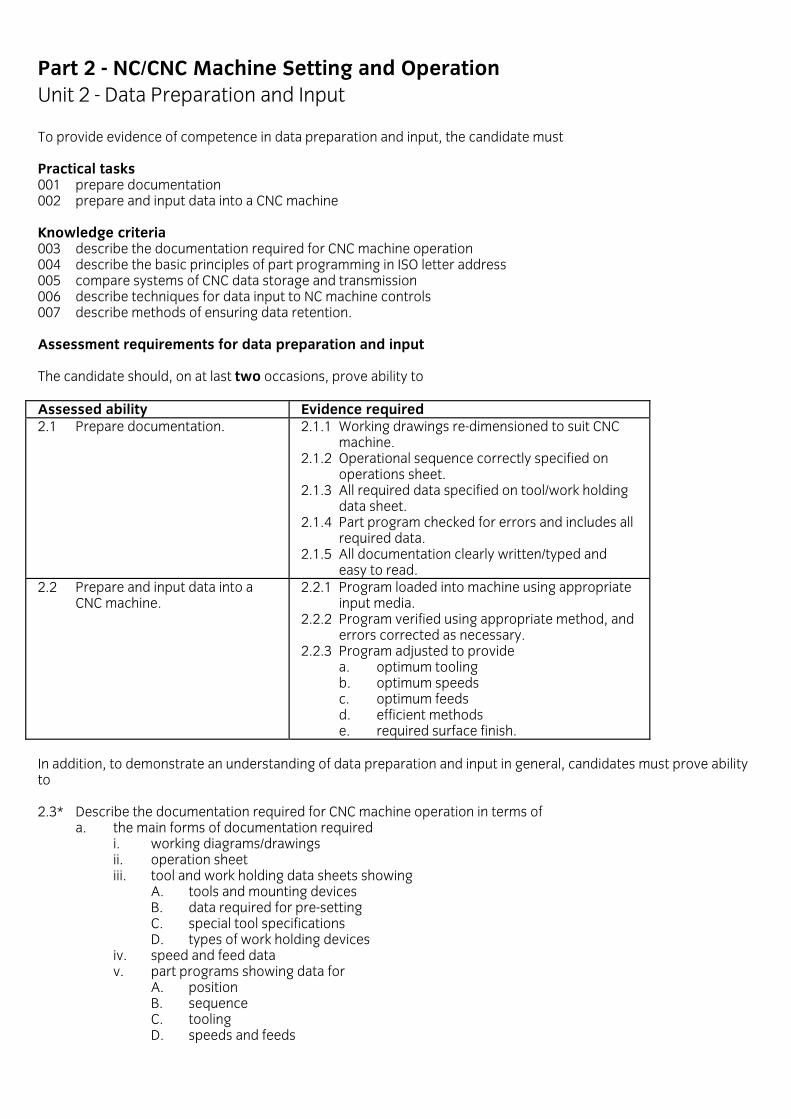
Part 2 - NC/CNC Machine Setting and Operation Unit 2 - Data Preparation and Input To provide evidence of competence in data preparation and input, the candidate must Practical tasks 001 prepare documentation 002 prepare and input data into a CNC machine Knowledge criteria 003 describe the documentation required for CNC machine operation 004 describe the basic principles of part programming in ISO letter address 005 compare systems of CNC data storage and transmission 006 describe techniques for data input to NC machine controls 007 describe methods of ensuring data retention. Assessment requirements for data preparation and input The candidate should, on at last two occasions, prove ability to Assessed ability Evidence required 2.1 Prepare documentation. 2.1.1 Working drawings re-dimensioned to suit CNC
machine. 2.1.2 Operational sequence correctly specified on operations sheet. 2.1.3 All required data specified on tool/work holding data sheet. 2.1.4 Part program checked for errors and includes all required data. 2.1.5 All documentation clearly written/typed and easy to read.
2.2 Prepare and input data into a CNC machine.
2.2.1 Program loaded into machine using appropriate input media. 2.2.2 Program verified using appropriate method, and errors corrected as necessary. 2.2.3 Program adjusted to provide a. optimum tooling b. optimum speeds c. optimum feeds d. efficient methods e. required surface finish.
In addition, to demonstrate an understanding of data preparation and input in general, candidates must prove ability to 2.3* Describe the documentation required for CNC machine operation in terms of
a. the main forms of documentation required i. working diagrams/drawings ii. operation sheet iii. tool and work holding data sheets showing A. tools and mounting devices B. data required for pre-setting C. special tool specifications D. types of work holding devices iv. speed and feed data v. part programs showing data for A. position B. sequence C. tooling D. speeds and feeds

b. the essential differences between working drawings for conventional machinery and those required for CNC machine operation i. specification of datum ii. coordinate dimensioning (absolute, incremental).
2.4 Describe the basic principles of part programming in ISO letter address in terms of the requirement for
a. N: operation sequence number b. G: preparatory function for
i. rapid/linear movement ii. inch/metric units iii. absolute/incremental dimensioning iv. simple explanation of the use of assigned canned cycles
c. X, Y, Z: coordinate positional data d. F, S: feed and speed data e. T: tooling details f. M: miscellaneous functions
i. tool change ii. end of program, etc. iii. radius/tool length offsets iv. datum offsets. 2.5* Compare systems of CNC data storage and transmission in terms of
a. advantages and limitations of data storage media i. punched tape ii. magnetic tape iii. magnetic disk iv. direct NC link
b. characteristics of ISO and EIA tape coding systems: representation of dimensional and functional information.
2.6 Describe techniques for data input to NC machine controls in terms of
a. tape/cassette input i. techniques for loading tapes and cassettes ii. need to ensure compatibility between storage media and machine reader
b. manual data input iii. interpretation and entering of input instructions for MDI iv. alphanumeric keyboard layout v. typical console control functions and layout vi. use of the VDU
c. the need for care and cleanliness in the handling and storage of data input media d. the need for pre-operational checks and program proving to ensure intended outcome and prevention of
damage to equipment and work e. methods of verifying input data during pre-operational checks
i. VDU simulation ii. X, Y plotter iii. offset dry run
f. typical punched tape faults, errors and effects g. main facilities for manual over-ride of control and program proving h. machine search facilities for selection of particular blocks of data.
2.7* Describe methods of ensuring data retention in terms of
a. the need for back-up electrical supply to machine memory in case of power failure b. functions wiped from memory on shut-down, need to establish datums and offsets c. the need for, and methods of making permanent copies of input data after editing and verification.
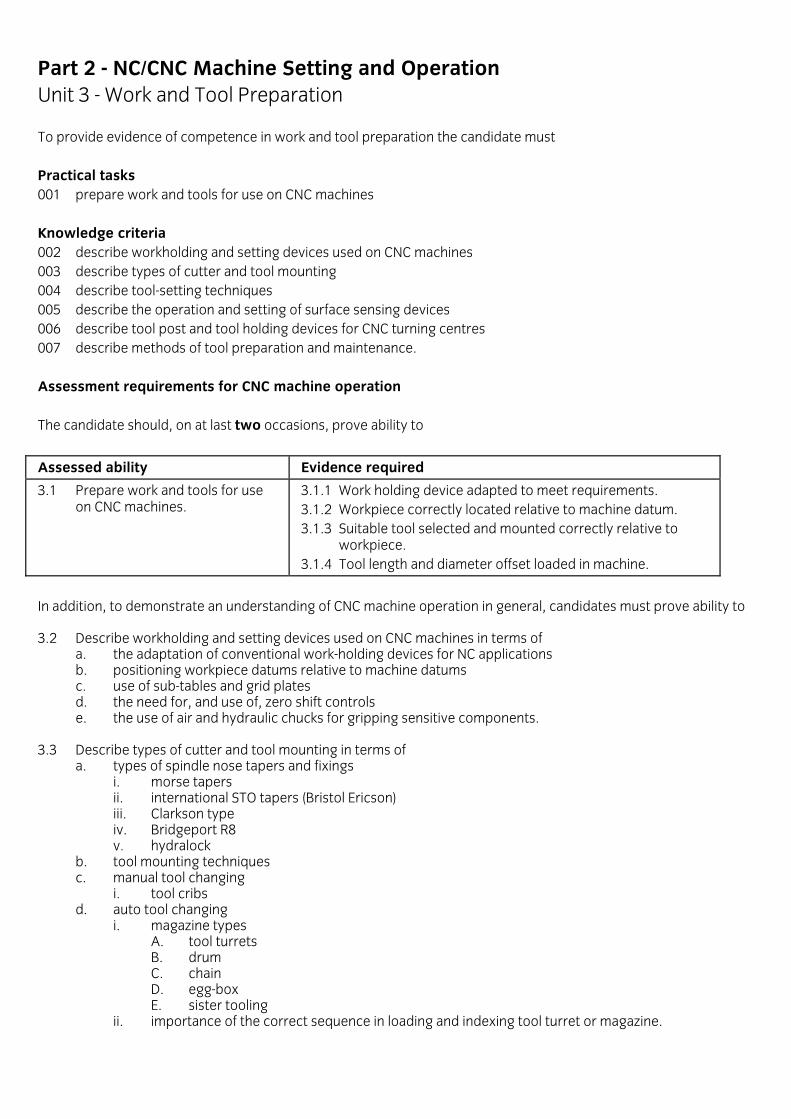
Part 2 - NC/CNC Machine Setting and Operation Unit 3 - Work and Tool Preparation To provide evidence of competence in work and tool preparation the candidate must Practical tasks 001 prepare work and tools for use on CNC machines Knowledge criteria 002 describe workholding and setting devices used on CNC machines 003 describe types of cutter and tool mounting 004 describe tool-setting techniques 005 describe the operation and setting of surface sensing devices 006 describe tool post and tool holding devices for CNC turning centres 007 describe methods of tool preparation and maintenance. Assessment requirements for CNC machine operation The candidate should, on at last two occasions, prove ability to
Assessed ability Evidence required
3.1 Prepare work and tools for use on CNC machines.
3.1.1 Work holding device adapted to meet requirements. 3.1.2 Workpiece correctly located relative to machine datum. 3.1.3 Suitable tool selected and mounted correctly relative to workpiece. 3.1.4 Tool length and diameter offset loaded in machine.
In addition, to demonstrate an understanding of CNC machine operation in general, candidates must prove ability to 3.2 Describe workholding and setting devices used on CNC machines in terms of
a. the adaptation of conventional work-holding devices for NC applications b. positioning workpiece datums relative to machine datums c. use of sub-tables and grid plates d. the need for, and use of, zero shift controls e. the use of air and hydraulic chucks for gripping sensitive components.
3.3 Describe types of cutter and tool mounting in terms of
a. types of spindle nose tapers and fixings i. morse tapers ii. international STO tapers (Bristol Ericson) iii. Clarkson type iv. Bridgeport R8 v. hydralock
b. tool mounting techniques c. manual tool changing
i. tool cribs d. auto tool changing
i. magazine types A. tool turrets B. drum C. chain D. egg-box E. sister tooling
ii. importance of the correct sequence in loading and indexing tool turret or magazine.

3.4 Describe tool-setting techniques in terms of a. use of tool length offset controls b. compensation for tool wear by use of cutter diameter offset controls c. use of diameters offset control to provide roughing and finishing cuts.
3.5 Describe the operation and setting of surface sensing devices
a. probes b. telescopes (optical) c. dia test indicators d. webbers.
3.6 Describe tool post and tool holding devices for CNC turning centres in terms of
a. typical devices i. tool post
A. qualified tool holders B. 4-way indexing turret (front and rear) C. rotary turret D. quick-release tool post
ii. tool holding A. solid (braze) B. clamp tip C. camlock tip
b. use of combined tool holder and tool preset prior to loading c. tool indexing devices.
3.7 Describe methods of tool preparation and maintenance in terms of
a. types of tool and their uses i. conventional tooling and adaptations ii. special tools iii. tipped tools
A. solid braced B. inserted tooth C. throw away (single and multi-point)
b. advantages and limitations of types of tool listed in a) c. factors affecting tool life
i. speed and feed rates ii. working shift length iii. operating conditions
d. the development of a tool library i. specification of tools within the library ii. advantages and limitations in using standardised tooling
e. techniques of checking cutting tool geometry i. tool angle comparators ii. optical projectors
f. pre-set tooling i. methods A. optical tool pre-setting instruments B. setting cards C. relationship between the distance the tool projects from the spindle and the gauge height of the machine ii. advantages and limitations
g. techniques of sharpening and maintaining cutting tools.
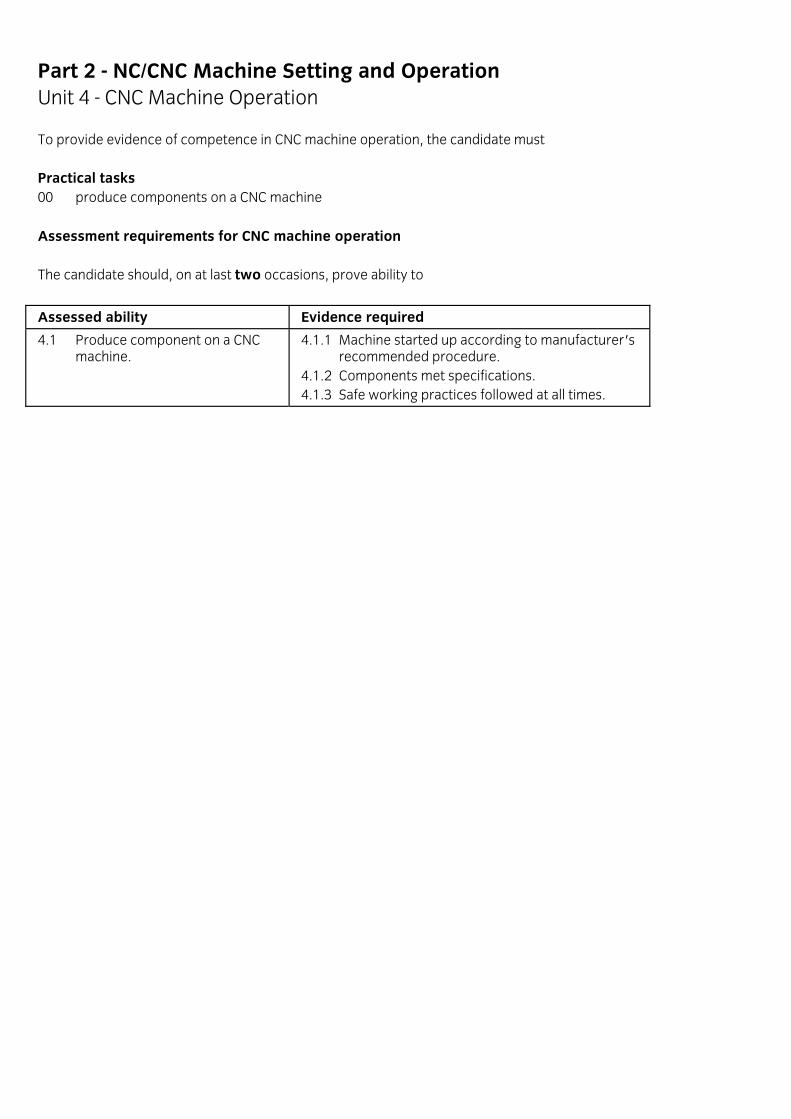
Part 2 - NC/CNC Machine Setting and Operation Unit 4 - CNC Machine Operation To provide evidence of competence in CNC machine operation, the candidate must Practical tasks 00 produce components on a CNC machine Assessment requirements for CNC machine operation The candidate should, on at last two occasions, prove ability to
Assessed ability Evidence required
4.1 Produce component on a CNC machine.
4.1.1 Machine started up according to manufacturer's recommended procedure. 4.1.2 Components met specifications. 4.1.3 Safe working practices followed at all times.

Part 2 - NC/CNC Part Programming
Introduction This scheme is intended to provide evidence of competence in CNC manual part programming techniques. The scheme does not assume previous study of CNC programming but does assume that students will have access to industrial scale CNC machinery. For most CNC applications, a knowledge of setting and operating considerations and techniques is seen as an important prerequisite if students are to benefit from this scheme (see NC/CNC Machine Setting and Operation). It is generally agreed that while CNC replaces many hand skills, its effective use still depends on knowledge intrinsic to conventional machining. In general terms, then, this scheme is intended for those who have already acquired (or will acquire concurrently) a sound understanding of machining technology.
Guidance Notes on NC/CNC Part Programming Course notes 1. Students should be made aware that the preparation of an efficient part programme will depend on rigorous
and careful planning before coding is started. 2. The example of practical work given in Appendix B gives an indication of the task complexity for which students
should be able to plan. 3. The following list is intended to suggest types of programming tasks which might be used to lead the student
progressively towards the level of programming complexity required for the practical assignment, using the same piece of material.
Program
• single point-to-point drill holes
• profile a rectangle
• drill two holes using a canned cycle
• use incremental programming to machine two holes with a canned cycle
• as 4 but with deep-hole canned cycle
• circular interpolation to profile a circular pocket
• circular interpolation to profile radii on four corners of the rectangle
• as 6 or 7, but using cutter diameter compensation
• profile deep external features using a loop for several passes. a. Coding used for manual part programming will depend on the machine control system. ISO letter address still
appears to be the most widely used, however, and students will be expected to be familiar with particular features of the system when presented for the written examination. Details are given in Appendix A. Coding used during practical work will naturally depend on local systems.
b. Students should become accustomed to producing required support documentation for all program exercises.
Comprehensive documentation will be required for the practical task (see Appendix B).
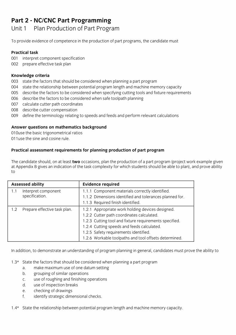
Part 2 - NC/CNC Part Programming Unit 1 Plan Production of Part Program To provide evidence of competence in the production of part programs, the candidate must Practical task 001 interpret component specification 002 prepare effective task plan Knowledge criteria 003 state the factors that should be considered when planning a part program 004 state the relationship between potential program length and machine memory capacity 005 describe the factors to be considered when specifying cutting tools and fixture requirements 006 describe the factors to be considered when safe toolpath planning 007 calculate cutter path coordinates 008 describe cutter compensation 009 define the terminology relating to speeds and feeds and perform relevant calculations Answer questions on mathematics background 010use the basic trigonometrical ratios 011use the sine and cosine rule. Practical assessment requirements for planning production of part program The candidate should, on at least two occasions, plan the production of a part program (project work example given at Appendix B gives an indication of the task complexity for which students should be able to plan), and prove ability to
Assessed ability Evidence required
1.1 Interpret component specification.
1.1.1 Component materials correctly identified. 1.1.2 Dimensions identified and tolerances planned for. 1.1.3 Required finish identified.
1.2 Prepare effective task plan. 1.2.1 Appropriate work holding devices designed. 1.2.2 Cutter path coordinates calculated. 1.2.3 Cutting tool and fixture requirements specified. 1.2.4 Cutting speeds and feeds calculated. 1.2.5 Safety requirements identified. 1.2.6 Workable toolpaths and tool offsets determined.
In addition, to demonstrate an understanding of program planning in general, candidates must prove the ability to 1.3* State the factors that should be considered when planning a part program
a. make maximum use of one datum setting b. grouping of similar operations c. use of roughing and finishing operations d. use of inspection breaks e. checking of drawings f. identify strategic dimensional checks.
1.4* State the relationship between potential program length and machine memory capacity.

1.5* Describe the factors to be considered when specifying cutting tools and fixture requirements
a. availability of tooling b. tool type and geometry c. tools required for particular operations d. position of clamp e. fixture requirements and datums.
1.6* Describe the factors to be considered when safe toolpath planning
a. ensure toolpath avoids collision with workholding or locating devices b. care with offset toolpaths c. collision free zones d. use of manual tool change position e. safety of operator, equipment and work.
1.7 Calculate cutter path coordinates for
a. intersections b. polar centres c. arcs d. blind points e. cutter approach/exit.
1.8 Describe cutter compensation
a. state the use of cutter compensation b. relate cutter compensation to
i. tool diameter ii. tool length iii. tool nose radius.
1.9 Define the terminology relating to speeds and feeds and perform relevant calculations
a. define the terms i. rpm ii. cps iii. feed/rev iv. mm/min
b. calculate appropriate feeds and speeds for work and tool materials c. state the need for modifying feed rates whilst profiling internal and external arcs.
In addition, to demonstrate a sufficient command of the technology to cope with minor changes, candidates must prove the ability to 1.10 Use the basic trigonometrical ratios
a. sine b. cosine c. tangent.
1.11 Use the sine and cosine rule
a. sine rule A = B = C sin A Sin B Sin C
b. cosine rule a2 = b2 + c2 - 2bc Cos A

Part 2 - NC/CNC Part Programming Unit 2 Write and Prove Part Program To provide evidence of competence in the production of part programs, the candidate must Practical task 001 write a part program 002 transpose to input media 003 prove and edit part program Knowledge criteria 004 state the meaning of terms relating to part programs and their relationship 005 define and state the use of the terms mirror image, scaling, transposing and rotation 006 describe common pre-set data formats 007 describe the absolute and incremental modes of programming 008 describe the principles of part programming in ISO letter address 009 describe the role of assigned canned cycles 010 describe techniques for improving the efficiency of part programming 011 state the advantages and disadvantages of media for NC data storage and transmission 012 describe coding systems used in the preparation of punched tape 013 describe the setting up of communications between computer and machine tool for downloading a part program 014 describe the importance of verifying part programs during pre-operational checks. Practical assessment requirements for writing and proving part programs The candidate should, on at least two occasions, a. write a program to produce a part (Appendix B gives an indication of the level of program complexity required). b. use two of the following types of media
i. disk ii. magnetic tape iii. paper tape iv. foil tape
and prove ability to
Assessed ability Evidence required
2.1 Write a part program. 2.1.1 Instructions arranged to suit machine data format. 2.1.2 Sequence of operations stated. 2.1.3 Canned cycles identified and incorporated. 2.1.4 Standard coding system used.
2.2 Transpose to input media. 2.2.1 Appropriate input medium identified. 2.2.2 Program successfully transposed without error.
2.3 Prove and edit part program. 2.3.1 Simulated production run carried out to prove program. 2.3.2 Program edited as necessary. 2.3.3 Final program produces component to required specification.

In addition, to demonstrate an understanding of part programming in general, candidates must prove the ability to 2.4 State the meaning of the following terms related to part programs and their relationship a. block of data b. block identifier c. letter address d. modal and non-modal codes. 2.5* State function codes which are incompatible within a block. 2.6 Describe common pre-set data formats a. give examples of common formats b. recognise shorthand notations i. use of leading and/or trailing zero suppression ii. decimal point within a word c. state and recognise typical faults which arise from input of incorrectly formatted information. 2.7 Describe the absolute and incremental modes of programming a. describe the main principles of i. absolute programming ii. incremental programming b. give typical uses of the programming modes listed in a). 2.8 Describe the principles of part programming in ISO letter address a. state the requirements for i. N: operation sequence number ii. G: preparatory functions iii. X, Y, Z, etc: coordinate positioning data (I, J for circular interpolation) iv. F, S: feed and speed data v. T: tooling details vi. M: miscellaneous functions b. state the function codes which are incompatible within a block. 2.9* Describe the role of assigned canned cycles
a. state what is meant by an assigned canned cycle b. state the role of assigned canned cycles c. describe the detailed operation of assigned canned cycles.
2.10 Describe techniques for improving the efficiency of part programming
a. state the advantages and disadvantages of unassigned (user defined) cycles b. describe the use of loops in terms of
i. loop calling blocks ii. loop terminating blocks iii. effects of loop on program sequence iv. nested loops, nesting limit
c. describe the use of sub-routines in terms of i. labelling of sub-routines: distinction between level and call statement ii. effect of calling a sub-routine on program sequence iii. specific position of sub-routines within program (for some systems).

2.11* State the advantages and disadvantages of media for NC data storage and transmission
a. paper b. plastic foil tape c. metallic foil tape d. magnetic tape e. disks.
2.12 Describe coding systems used in the preparation of punched tape a. state the characteristics of i. ISO ii. EIA iii. ASCII tape coding systems with regard to dimensional and functional information b. describe methods of detecting tape errors i. parity ii. channel iii. checksum data. 2.13* Describe the setting up of communications between computer and machine tool for downloading a part program. 2.14* Describe the importance of verifying part programs during pre-operational checks in terms of
a. protection of operator b. protection of tooling c. protection of work.
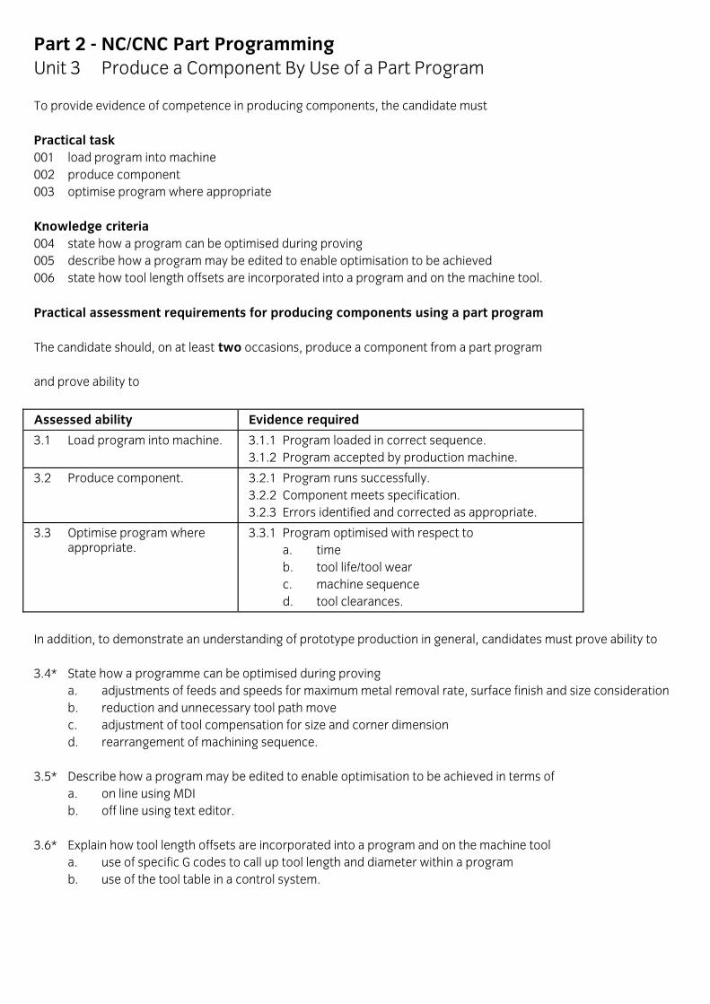
Part 2 - NC/CNC Part Programming Unit 3 Produce a Component By Use of a Part Program To provide evidence of competence in producing components, the candidate must Practical task 001 load program into machine 002 produce component 003 optimise program where appropriate Knowledge criteria 004 state how a program can be optimised during proving 005 describe how a program may be edited to enable optimisation to be achieved 006 state how tool length offsets are incorporated into a program and on the machine tool. Practical assessment requirements for producing components using a part program The candidate should, on at least two occasions, produce a component from a part program and prove ability to
Assessed ability Evidence required
3.1 Load program into machine. 3.1.1 Program loaded in correct sequence. 3.1.2 Program accepted by production machine.
3.2 Produce component. 3.2.1 Program runs successfully. 3.2.2 Component meets specification. 3.2.3 Errors identified and corrected as appropriate.
3.3 Optimise program where appropriate.
3.3.1 Program optimised with respect to a. time b. tool life/tool wear c. machine sequence d. tool clearances.
In addition, to demonstrate an understanding of prototype production in general, candidates must prove ability to 3.4* State how a programme can be optimised during proving
a. adjustments of feeds and speeds for maximum metal removal rate, surface finish and size consideration b. reduction and unnecessary tool path move c. adjustment of tool compensation for size and corner dimension d. rearrangement of machining sequence.
3.5* Describe how a program may be edited to enable optimisation to be achieved in terms of a. on line using MDI b. off line using text editor. 3.6* Explain how tool length offsets are incorporated into a program and on the machine tool
a. use of specific G codes to call up tool length and diameter within a program b. use of the tool table in a control system.

Part 2 - NC/CNC Part Programming Unit 4 Document a Part Program To provide evidence of competence in the documenting of a part program, the candidate must Practical task 001 produce program documentation 002 produce operator's instructions Knowledge criteria 003 describe the documentation required to supplement a part program. Practical assessment requirements for documenting a part program The candidate should, on at least two occasions, document a part program and prove ability to
Assessed ability Evidence required
4.1 Produce program documentation.
4.1.1 Program header correct. 4.1.2 Machining sequence correct. 4.1.3 Workholding requirement identified. 4.1.4 Tools and tool settings identified. 4.1.5 Tool compensation and program sequence determined. 4.1.6 All documentation clear and precise.
4.2 Produce operator's instructions.
4.2.1 Loading instructions complete and accurate. 4.2.2 Document location clearly identified. 4.2.3 Program stored securely according to medium. 4.2.4 Program documentation filed and indexed.
In addition, to demonstrate an understanding of part program documentation in general, candidates must prove the ability to 4.3 Describe the documentation required to supplement a part program a. drawing b. operation sheet c. tooling list (cutters and fixtures) d. operator's instructions.

Part 2 - NC/CNC Part Programming Unit 5 CNC Machining Principles To provide evidence of competence in CNC part programming, the candidate must Knowledge criteria 001 describe the basic principles of numerical control 002 describe the fundamentals of computer systems. Assessment requirements for CNC machining principles To demonstrate an understanding of CNC machining principles in general, candidates must prove ability to 5.1 Describe the basic principles of numerical control
a. outline the use of binary notation for information encoding b. distinguish between open- and closed-loop control c. state the applications of
i. point to point for A. drilling B. boring C. punching ii. continuous path control for A. profile cutting
d. state the application of servo-stepping motion e. state the basic role of linear and rotary position transducers f. define the relationship of CNC machine axes
i. primary ii. secondary
g. state the purpose of a machine datum h. describe the principles of coordinate dimensioning in terms of
i. the importance of coordinate planning and calculation in the preparation of working drawings ii. the difference between absolute and incremental co-ordinate dimensioning methods iii. applications of absolute and incremental co-ordinate dimensioning.
5.2 Describe the fundamentals of computer systems
a. outline the concept of a stored program b. distinguish between dedicated and general purpose computers c. state the main elements of a computer system
i. input devices ii. output devices iii. central processing unit iv. memory
d. distinguish between hardware and software e. define the terms
i. bits ii. bytes iii. words iv. character v. kilobyte.

APPENDIX A Standard coding system Students will be expected to be familiar with the following function codes when presented for written examination. G 00 Rapid movement.. point-to-point G 01 Linear interpolation G 02 Clockwise circular interpolation G 03 Counter clockwise circular interpolation G 04 Dwell G 40 Cancel cutter diameter compensation G 41 Cutter diameter compensation left G 42 Cutter diameter compensation right G 70 Inch G 71 Metric G 90 Absolute G 91 Incremental G 92 Preset position G 94 Feed setting as mm/min G 95 Feed in mm per rev G 96 Constant surface speed G 97 Direct rpm programming M 00 Program stop M 01 Optional stop M 02 End program M 03 Spindle on negative clockwise M 04 Spindle on positive counter clockwise M 05 Spindle off M 06 Tool change M 07 Mist coolant on M 08 Flood coolant on M 09 Coolant off M 30 End of tape

APPENDIX B
NC/CNC Part Programming
Guidelines for practical work
Introduction These notes for course tutors are intended to explain
• how the practical work might be organised and what level should be aimed at
• how students' practical work should be assessed.
Practical work: organisation and level Tutors should aim to devise practical tasks in programming which correspond closely to industrial tasks and where practicable involve students' employers in the formulation process. Machine setting and clamping considerations, however, should be kept relatively simple. Programs produced should be run by the student and `debugged' by the student. Examples of practical work, annexed to the Appendices, are intended to give an indication of the minimum level of programming complexity for a practical task appropriate to this scheme.
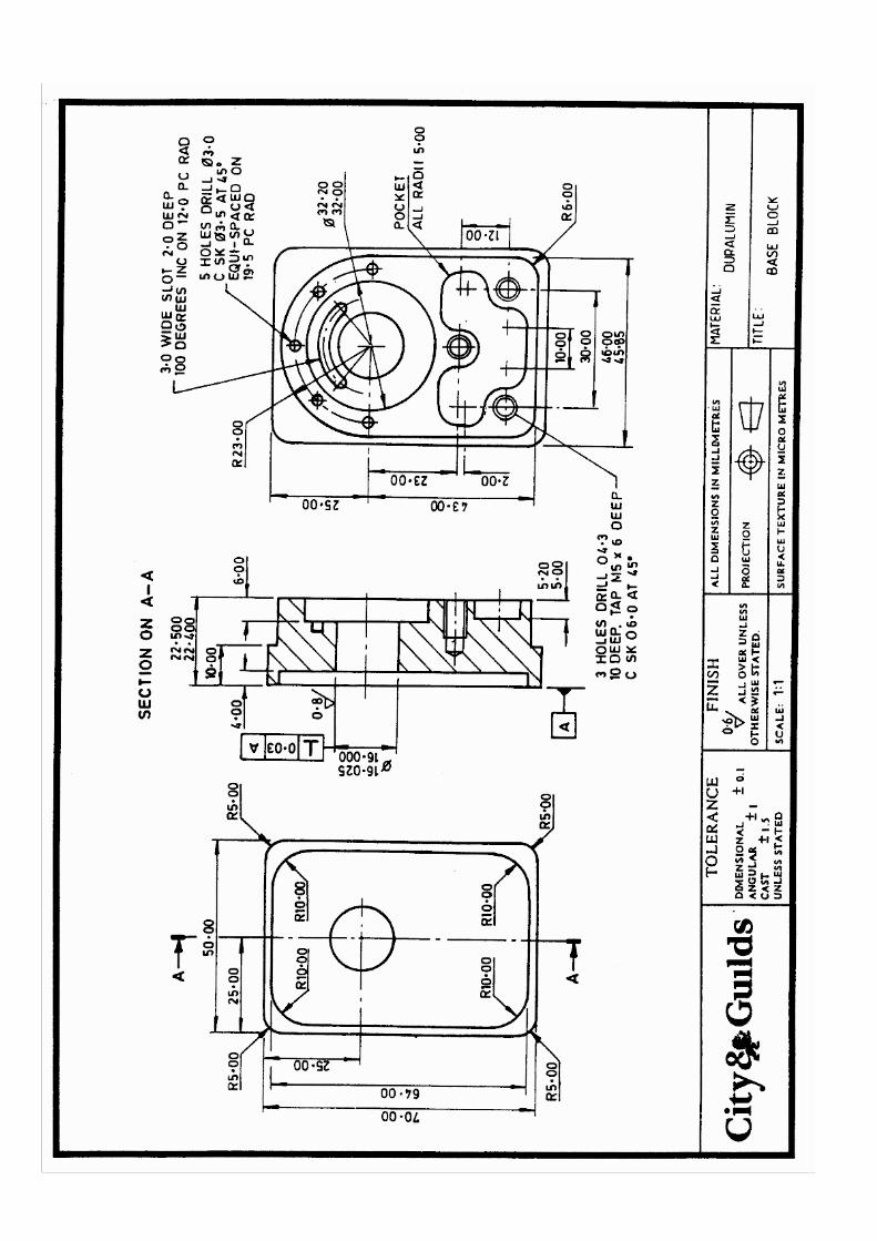
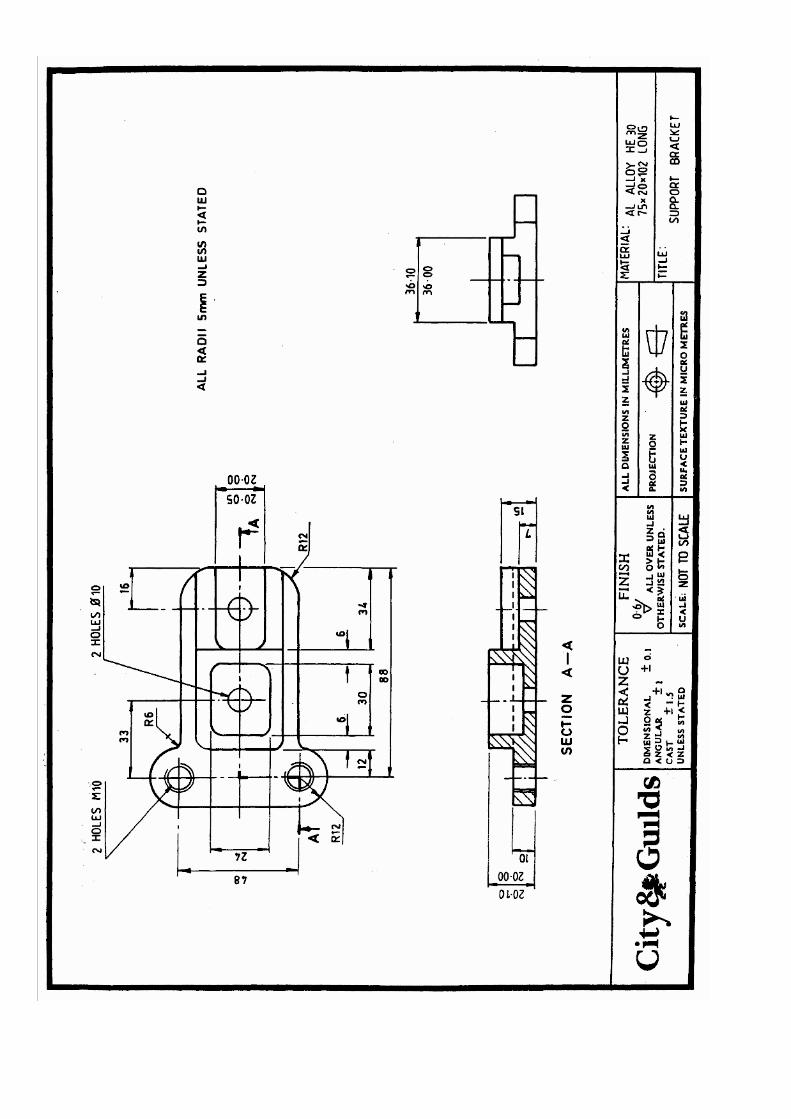
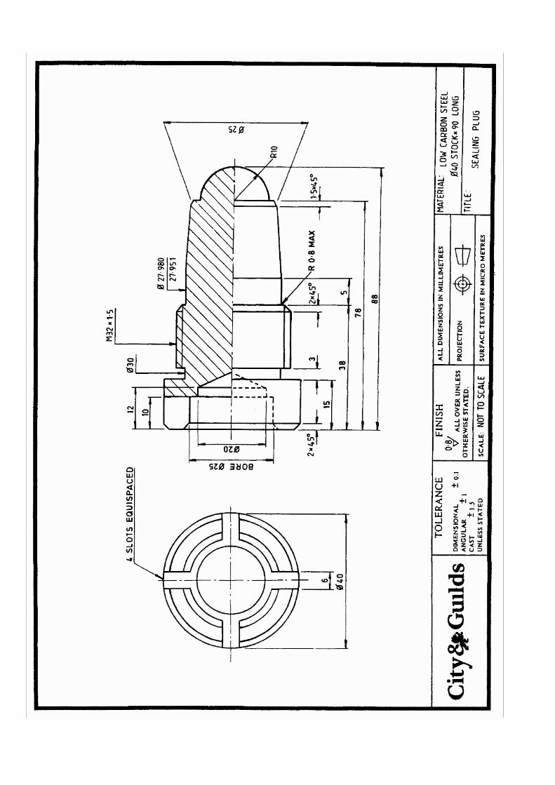

Part 2 - Computer-aided Draughting
Introduction This scheme takes the production engineering context as its model, but with suitably designed project work it will be appropriate for a range of draughting applications, e.g. civil engineering, architecture, electronic circuit draughting. The scheme does not aim to produce personnel trained to operate all industrial computer-aided draughting systems; the variety of equipment and detailed procedures makes this impossible. The scheme does aim to: a. enable students to identify the operating framework of any industrial CA draughting system, b. significantly reduce the lead time to the attainment of competence on particular CA draughting systems. It is generally agreed that the `computer-aided draughtsman' still requires all the conventional knowledge and skills intrinsic to his/her draughting field; this scheme should therefore be seen as additional to conventional draughting training and not as an alternative. The student should therefore be competent to perform the following conventional draughting tasks prior to this scheme
• use draughting instruments
• use orthographic third angle projection in the construction of engineering drawings
• project auxiliary views
• apply measurement systems
• apply dimensioning systems
• apply ISO isometric or BS tolerance systems
• construct sectional views
• execute geometric constructions
• detail threads and fastening devices
• construct pictorial views
• develop surface and plane intersections
• apply basic concepts of descriptive geometry.

Guidance Notes Course notes Students should be aware that, as with conventional draughting, it is still usually necessary to prepare a paper sketch and notes of the work to be draughted. Students should use software for linework, text, dimensioning, cross-hatching, overlaying and calculation. It is recognised that some industrial systems will not have, or will not require some manipulation software or colour facilities. Students will, however, be expected to know what these facilities are and how they can be used. Students should be given, as far as possible, access to manufacturers' literature, films, videos and other sources of information to assist them. Assessment validation notes 1. Examples of practical work are attached to the end of this particular scheme. 2. Practical tasks are assessed against the criteria specified in the syllabus under "Evidence Required".
Part 2 - Computer-aided Draughting Unit 1 Initialise a Computer-aided Draughting System To provide evidence of competence in initialising a CAD system, , the candidate must Practical tasks 001 start up a CAD system and execute software 002 configure a CAD drawing 003 service peripheral material requirements Knowledge criteria 004 describe the correct setting up and operating procedures 005 describe the types of software required for a CAD system 006 state the advantages and potential problems of CAD compared to conventional draughting techniques 007 describe the advantages and disadvantages of CAD hardware and software features 008 describe routine care and maintenance procedures. Assessment requirements for initialising a CAD system The candidate should, on at least two occasions, configure the hardware/soft and initialise a CAD system and prove ability to
Assessed ability Evidence required
1.1 Start up a CAD system and execute software.
1.1.1 Operating system identified. 1.1.2 Login procedure completed. 1.1.3 CAD software and user files located and identified. 1.1.4 Correct operating mode identified and CAD software loaded. 1.1.5 Correct screen display and system prompts indicated.
1.2 Configure a CAD drawing 1.2.1 Drawing file selected and labelled. 1.2.2 Storage location identified. 1.2.3 Standard sheet size selected and non-standard size sheet size created. 1.2.4 Drawing scale created, line types and settings selected. 1.2.5 Text and dimension settings selected. 1.2.6 Drawing origin locate and set; x, y and z zero reference datum created.
1.3 Service peripheral material requirements.
1.3.1 Paper size and orientation selected. 1.3.2 Printer and plotter loaded with paper. 1.3.3 Paper clamping and feed mechanisms set correctly. 1.3.4 Power isolated and access cleared. 1.3.5 Ribbon on printer removed and replaced with new one, if required, and position checked for correct operation. 1.3.6 Pens in plotter replaced in terms of colour and size and checked for correct operation.
In addition, to demonstrate an understanding of initialising a CAD system in general, candidates must prove the ability to

1.4 Describe the correct setting up and operating procedures in terms of a. basic operating procedure i. switch on power and login ii. load/call up CAD software iii. establish draughting task parameters iv. undertake drawing assignment v. produce hard copy vi. save/file drawing for subsequent use vii. log out and switch off power b. setting draughting parameters i. scale ii. size of drawing frame iii. grid factor iv. text and line style v. layer and/or object name c. peripherals: input and output procedures i. use of keyboard, layout of tablet ii. storage to disk/retrieve procedure iii. activating plotter/printer devices d. help facilities, purpose of and methods of interrogating the computer. 1.5* Describe the types of software required for a CAD system in terms of a. operational software i. control of general operation of system A. memory allocation B. scheduling C. driving I/O devices ii. general housekeeping, eg filing, sorting, execution of program b. graphics or CAD software i. creation ii. manipulation iii. editing iv. storage c. user software i. user developed, eg creation of macros, symbols, library components, customising menus, parametrics d. applications software i. software particular to application, eg stress analysis, parts listing, costing, routing, thermal properties, electrical power. 1.6 Describe the advantages and potential problems of CAD compared to conventional draughting techniques a. advantages
i. increased productivity ii. rapid creation, checking and editing of graphical data iii. memory facilities: standard parts, symbols, parts lists iv. improved product quality v. uniform reproduction vi. style variety vii. major storage space saving
b. potential problems i. impact of new technology on working practices.

1.7* Describe the advantages and disadvantages of CAD hardware and software features in terms of
a. implications of dedicated, shared host and networked system operation b. comparison of data input methods
i. menu tablet - pen or mouse ii. alphanumeric keyboard iii. digitiser iv. joystick v. cursor control vi. combinations
in terms of vii. capital cost viii. user friendliness ix. access speed x. maintainability
c. hard copy/storage media i. plotters
A. flat bed/slotbed B. drum C. electrostatic D. pinch roll
ii. printers A. dot matrix B. electrostatic C) laser
iii. storage A. hard disk B. floppy disk C. disk pack D. tape 1. cartridge 2. streamer
d. consideration of hard copy/screen facilities in terms of i. resolution ii. accuracy iii. repeatability iv. paper size(s) v. consumables, e.g. ink
e. trade off between commercial and in-house software development in terms of i. cost ii. appropriateness iii. dependence on external expertise. 1.8* Describe routine care and maintenance procedures in terms of
a. routine care and maintenance of plotters and printers, etc, checking leads, contacts b. changing of pens, inks etc.
Part 2 - Computer-aided Draughting Unit 2 Produce Drawings Using CAD Equipment To provide evidence of competence in the production of drawings on a CAD system, the candidate must Practical tasks 001 produce technical drawings on a CAD system Knowledge criteria 002 state the setting draughting parameters to be considered when producing a drawing 003 state the software commands needed to create and manipulate graphical data 004 state the purpose and advantages of customising menus. Assessment requirements for producing drawings using CAD equipment The candidate should, on at least two occasions, prove ability to
Assessed ability Evidence required
2.1 Produce technical drawings on a CAD system.
2.1.1 Drawing task parameters are established and drawing checklist completed. 2.1.2 Geometry accurately created and manipulated using correct commands and/or menus. 2.1.3 Dimensions and text added in correct layout. 2.1.4 Hard copy initiated using appropriate commands. 2.1.5 Drawing stored and saved using correct commands. 2.1.6 Exited CAD program and correctly closed down ystem.
In addition, to demonstrate an understanding of drawing production on a CAD system in general, candidates must prove ability to 2.2* tate the setting draughting parameters to be considered when producing a drawing 2.3* tate the software commands needed to create and manipulate graphical data
a. linework i. straight lines A. horizontal B. vertical C. angled ii. line type A. continuous B. short dashes C. long chain D. short chain E. centre lines iii. line style A. light B. heavy

iv. circular features A. circles B. arcs C. segments D. blend radii E. fillet radii F. tangents b. secondary functions i. chamfers ii. fillets iii. cross-hatching c. text i. location ii. font type iii. font size iv. line weight v. aspect d. dimensioning i. linear - leader lines with arrowheads ii. angular iii. circular iv. text v. tolerancing vi. automatic/follow through dimensioning e. construction aids i. points ii. centre lines f. manipulation/editing i. zoom in/zoom out ii. mirroring iii. scaling iv. panning v. rotating vi. deleting vii. selecting viii. moving ix. trimming g. overlayering i. setting and use of different drawing layers h. calculation of i. areas ii. lengths iii. angles i. use, and methods of i. colouring ii. texturing iii. shading iv. blocking. 2.4* State the purpose and advantages of customising menus a. purpose b. advantages

Part 2 - Computer-aided Draughting Unit 3 Modify Drawings on a CAD System To provide evidence of competence in modifying drawings on a CAD system, the candidate must Practical tasks 001 retrieve an item from a library file 002 modify drawings using CAD commands Knowledge criteria 003 state the function of the main editing commands 004 state the correct software commands for editing graphical data 005 describe the importance of maintaining careful filing systems for manual reference and disk storage 006 state why draughted software needs to be protected and in which ways it can be secured. Assessment requirements for editing drawings on a CAD system The candidate should, on at least two occasions, prove ability to
Assessed ability Evidence required
3.1 Retrieve an item from a library file.
3.1.1 Item identified and successfully retrieved using appropriate commands. 3.1.2 Appropriate scale and orientation selected.
3.2 Modify drawings using CAD commands.
3.2.1 Drawing modified to new specification using appropriate commands 3.2.2 Revised drawing added to library and older version deleted (as required).
In addition, to demonstrate an understanding of editing on a CAD system in general, candidates must prove ability to 3.3 Explain the function of the main editing commands
a. zoom in/zoom out b. mirroring c. scaling d. panning e. rotating f. deleting g. selecting h. moving i. trimming.
3.4* State the correct software commands for editing graphical data
a. delete commands b. viewing.
3.5* Describe the importance of maintaining careful filing systems for manual reference and disk storage in terms of a. file management
i. creation and maintenance of manual reference files for ease of access ii. index system for storage of disks
b. memory availability i. effective use of temporary, semi-permanent and permanent memory storage facilities.

3.6* State why draughted software needs to be protected and in which ways it can be secured a. physical i. requirement for backup storage to protect against eg fire, software corruption, theft b. access i. passwords, to limit user access where required.
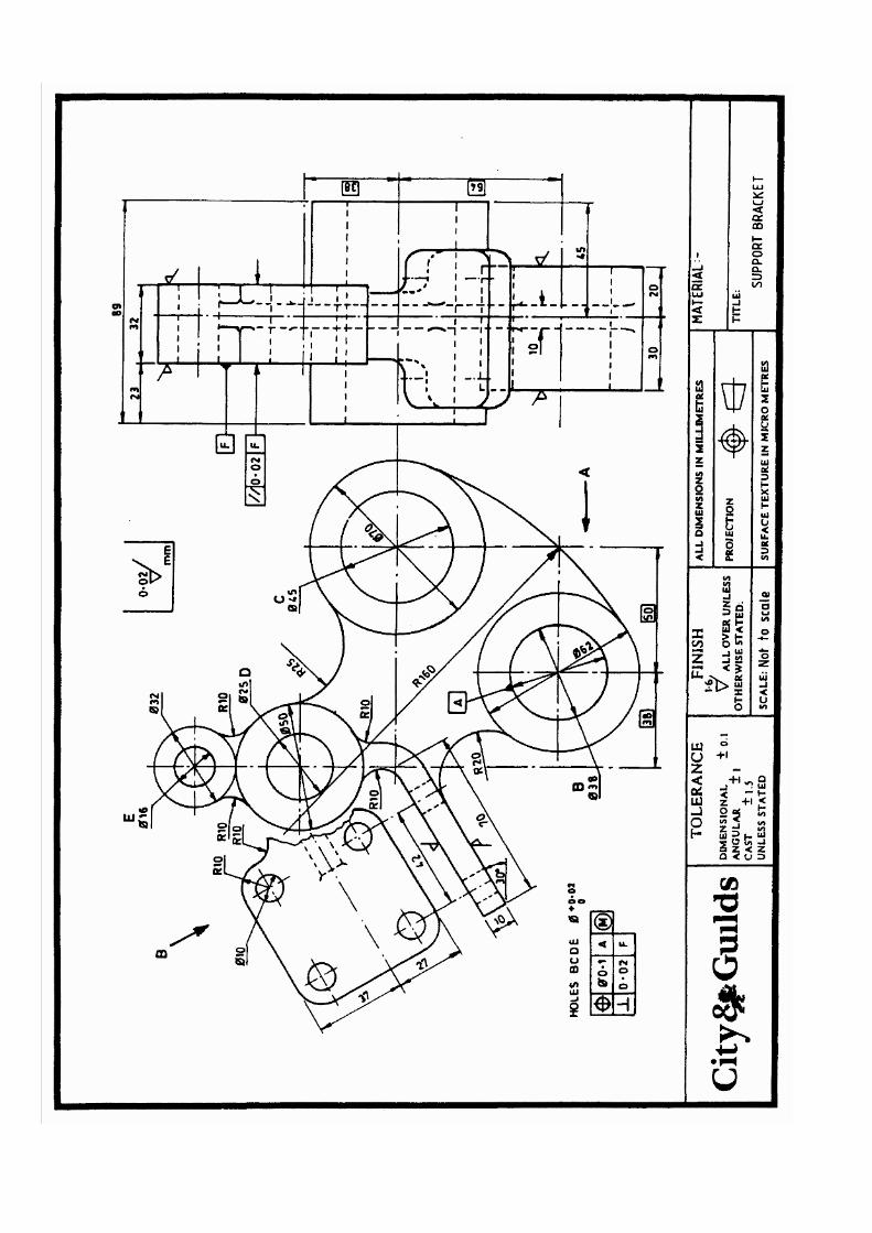
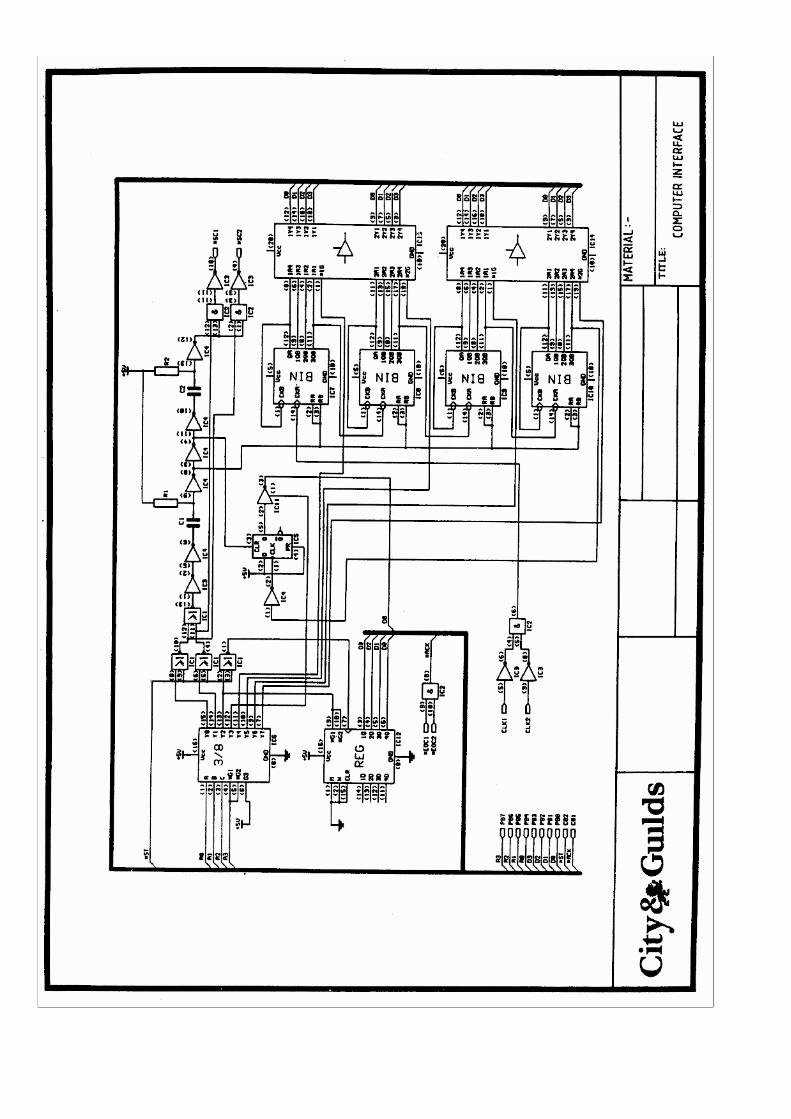
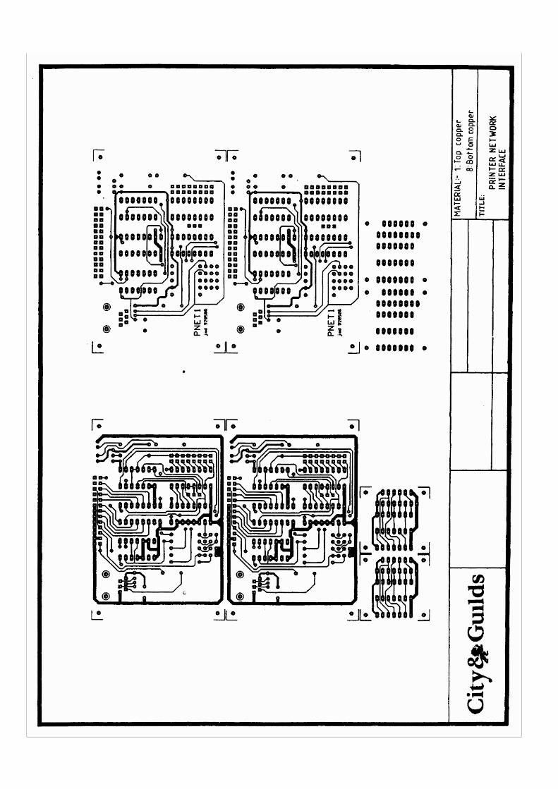
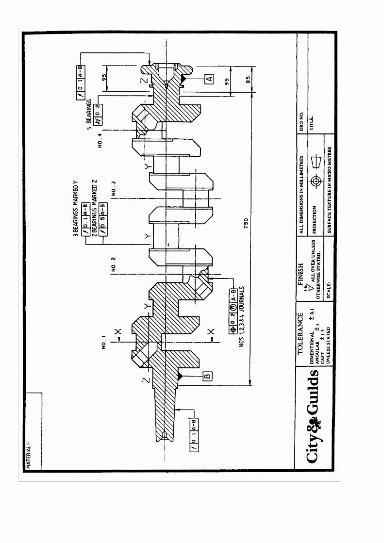
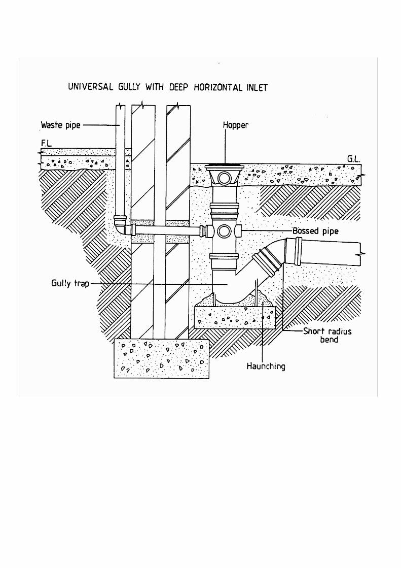
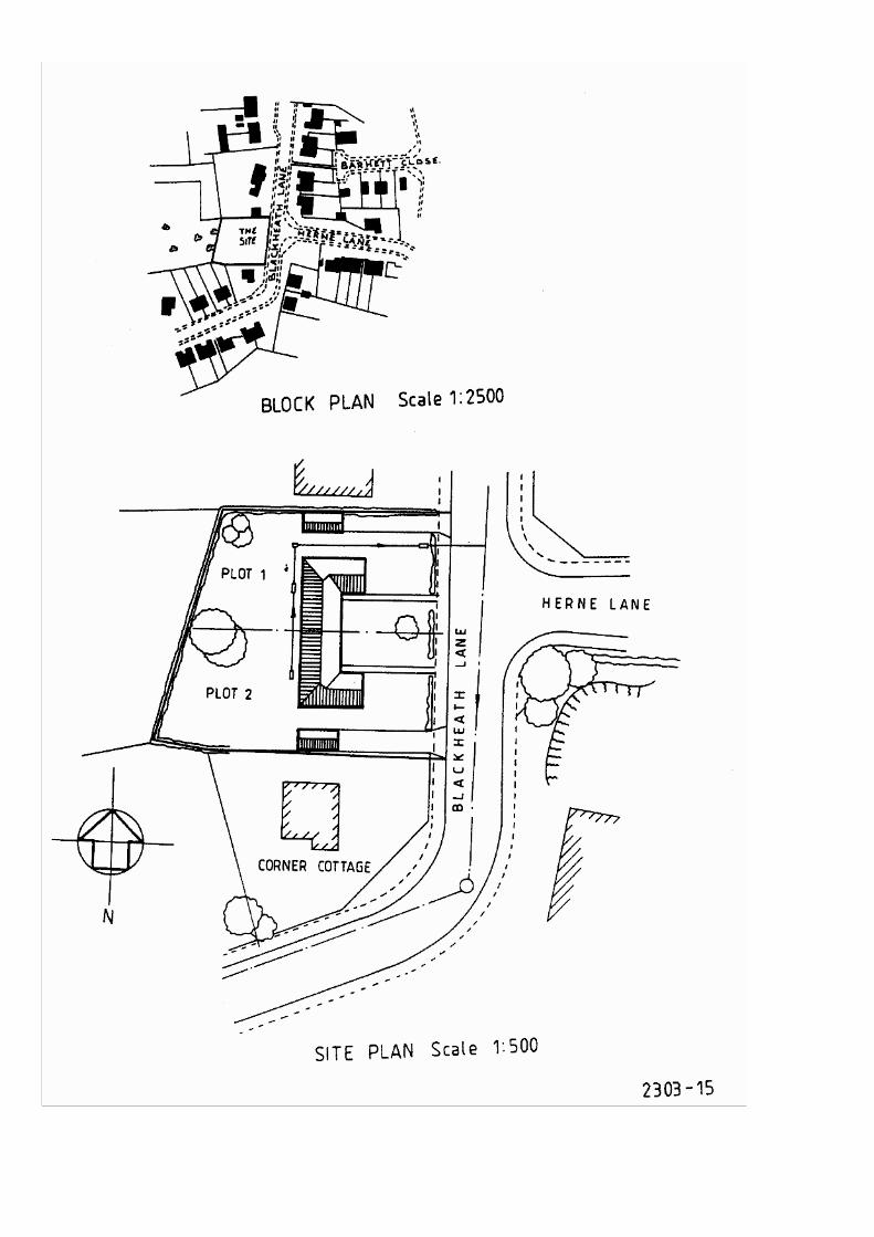
Part 2 - Robot Technology and Control
Introduction This scheme is intended primarily for plant and maintenance engineering personnel who may become involved in automation applications engineering, or installation, commissioning, servicing and maintenance of automated plant. The scheme is designed
• to enable students to acquire a sound understanding of the general characteristics of robotic devices, and the techniques and systems used to provide power and control
and
• significantly reduce the lead time required for the development of competence to undertake particular roles. Students for this scheme will have already attained a general level of competence in a plant/maintenance discipline, e.g. mechanical, electrical, electronics, instrumentation. Working with modern plant, however, increasingly demands multi-discipline competences, and this scheme has been designed therefore to enable students to acquire an understanding of power/control systems normally associated with other disciplines.

Part 2 - Robot Technology and Control Unit 1 Robot Technology To provide evidence of competence in robot technology the candidate must Knowledge criteria 001 describe the main mechanical systems used in robots 002 describe the mechanical devices used to transmit motion in a robot system 003 describe the actuation and drive systems used in robots 004 describe the sensing devices used in robots 005 describe the safety requirements of robot systems. To demonstrate an understanding of robot technology in general, candidates must prove ability to 1.1 Describe the main mechanical systems used in robots in terms of
a. the main classes of configuration i. cartesian (X Y Z) ii. cylindrical iii. revolute iv. polar v. SCARA vi. revolute with pantograph link vii. hybrid
b. types of arm joints i. revolute ii. prismatic
c. wrist articulation i. movements A. yaw B. pitch C. roll ii. additional effect of degrees of freedom
d. types of mounting i. fixed ii. slide iii. vehicle
e. types of end effector and their uses i. mechanical gripper and hooks ii. vacuum cups iii. magnetic pickups iv. scoops and ladles v. adhesive pads vi. tools
A. welding head B. spraying head C. drilling, routing and grinding heads.

1.2 Describe the mechanical devices used to transmit motion in a robot system in terms of a. types and function of mechanisms
i. belts ii. pulleys and linkages iii. gears iv. screwthreads v. couplings vi. clutches and brakes vii. rotary joints and universal knuckles viii. ball, screw and harmonic drives ix. bearings
b. causes and correction of mechanical faults i. misalignment ii. maladjustment iii. wear.
1.3 Describe the actuation and drive systems used in robots in terms of
a. the basic principle of operation of i. ac and dc electric drives ii. digital (stepping) motors iii. hydraulic and pneumatic servo-actuators
b. the advantages and disadvantages of listed actuators in terms of i. power/weight ratio ii. speed of response iii. reliability iv. accuracy v. cost
c. common faults d. importance and type of routine maintenance of actuator drive systems.
1.4 Describe the sensing devices used in robots in terms of
a. the principles and application of common sensing devices i. tactile sensors
A. microswitches B. piezo-electric devices C. resistance transducers D. strain gauges
ii. non-tactile sensors A. light sensitive transducer types, photo-conductive, photo-voltaic, photo-emissive B. hall effect transducers C. reed switch sensors D. inductance and capacitive proximity sensors E. infra-red proximity sensors F. ultrasonic ranging sensors G vidicon tube and solid state (ccd) camera vision sensing H. laser ranging sensors
b. the factors affecting the choice of sensing device used i. position ii. proximity/range iii. orientation/aspect iv. force/torque v. size vi. shape

c. environmental sources of error in sensing devices i. noise ii. vibration iii. heat iv. light interference.
1.5 Describe the safety requirements of robot systems in terms of
a. safe working practices for i. operators ii. maintenance personnel
b. the types and sources of hazard arising from robot operation c. common safety devices and procedure found with the use of industrial robots
i. interlocks ii. dead man's post iii. pressure mats iv. hold (freeze) buttons

Part 2 - Robot Technology and Control Unit 2 Programming A Robot To provide evidence of competence in robot programming the candidate must Practical tasks 001 program a robot to perform simple tasks Knowledge criteria 002 state the main operational elements of a robot control system 003 describe methods of data input, transfer and storage 004 describe the operational characteristics of a robot system 005 describe methods of programming a robot control system. Assessment requirements for programming a robot The candidate should on at least two occasions, carry out each of the following tasks
a. write and run a pick-and-place program using a direct programming techniques b. write a program incorporating sensor input interrupts
and thus prove ability to
Assessed ability Evidence required
2.1 Program a robot to perform simple tasks.
2.1.1 Program written using correct language and data. 2.1.2 Program entered correctly. 2.1.3 Robot performs required movement in correct sequence and in a safe and efficient manner.
In addition, to demonstrate an understanding of programming a robot in general, candidates must prove ability to 2.2* State the main operational elements of a robot control system
a. program b. input device c. controller d. interfaces e. data storage f. actuators g. internal feedback transducers h. external sensors.
2.3 Describe methods of data input, transfer and storage
a. comparison of input methods i. hypads ii. telemanipulator
b. digital signal transfer and processing c. interfacing, translation/conversion of information d. information storage and retrieval.

2.4 Describe the operational characteristics of a robot system in terms of
a. uses of internal control feedback devices i. analogue resolvers ii. digital encoders iii. tachogenerators
b. causes, effect and control of factors affecting programme i. friction ii. backlash iii. stiffness iv. inertia v. momentum vi. drift vii. vibration viii. noise ix. commutative actuation problem x. drag of power services
c. limitations of a robot system due to factors listed in b). 2.5 Describe methods of programming a robot control system in terms of a. procedures and applications of common programming methods i. off-line ii. lead through iii. walk through iv. telemanipulation v. speech synthesis b. program editing techniques c. use of i. ramping ii. delays iii. halts iv. interrupts d. graphical and interactive programming techniques e. control techniques i. adaptive ii. point-to-point iii. continuous path.
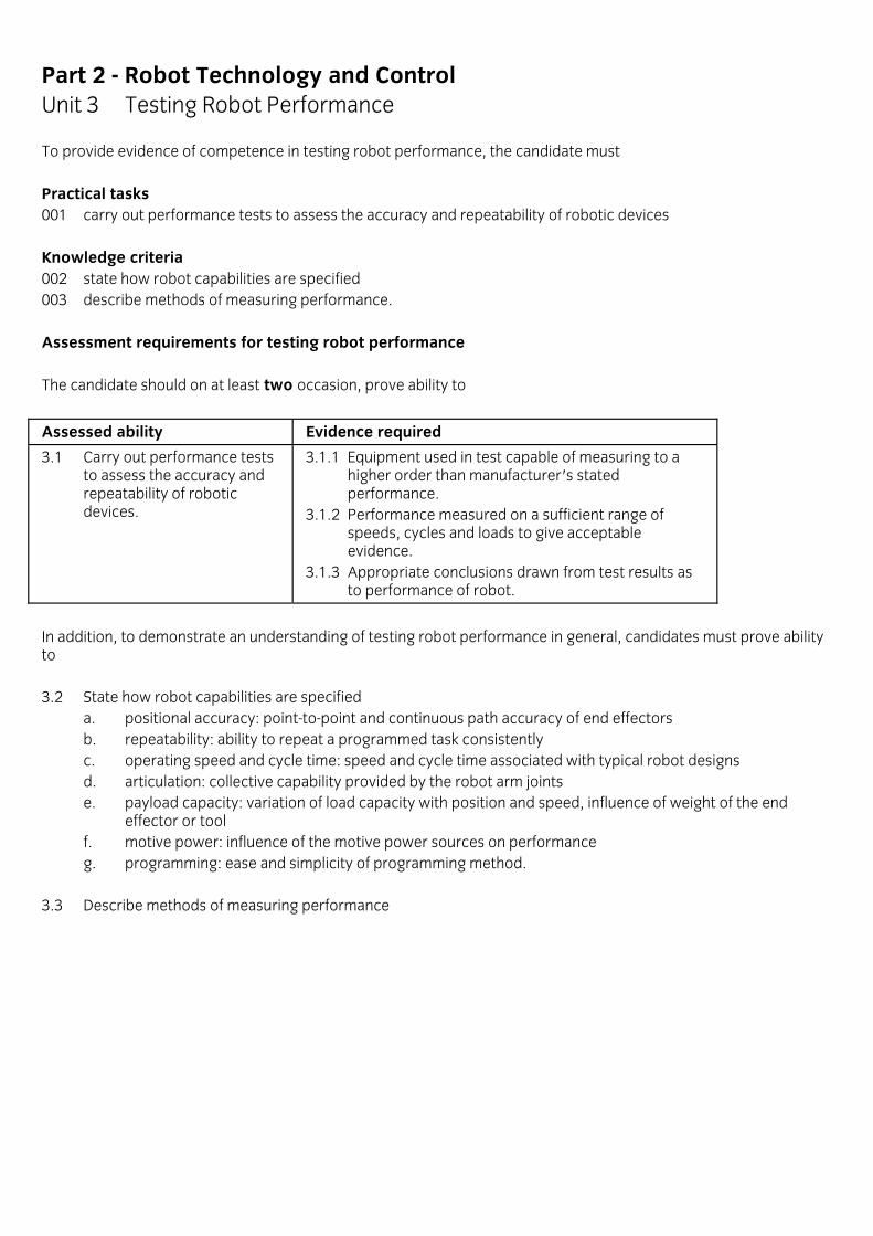
Part 2 - Robot Technology and Control Unit 3 Testing Robot Performance To provide evidence of competence in testing robot performance, the candidate must Practical tasks 001 carry out performance tests to assess the accuracy and repeatability of robotic devices Knowledge criteria 002 state how robot capabilities are specified 003 describe methods of measuring performance. Assessment requirements for testing robot performance The candidate should on at least two occasion, prove ability to
Assessed ability Evidence required
3.1 Carry out performance tests to assess the accuracy and repeatability of robotic devices.
3.1.1 Equipment used in test capable of measuring to a higher order than manufacturer's stated performance. 3.1.2 Performance measured on a sufficient range of speeds, cycles and loads to give acceptable evidence. 3.1.3 Appropriate conclusions drawn from test results as to performance of robot.
In addition, to demonstrate an understanding of testing robot performance in general, candidates must prove ability to 3.2 State how robot capabilities are specified
a. positional accuracy: point-to-point and continuous path accuracy of end effectors b. repeatability: ability to repeat a programmed task consistently c. operating speed and cycle time: speed and cycle time associated with typical robot designs d. articulation: collective capability provided by the robot arm joints e. payload capacity: variation of load capacity with position and speed, influence of weight of the end
effector or tool f. motive power: influence of the motive power sources on performance g. programming: ease and simplicity of programming method.
3.3 Describe methods of measuring performance

Part 2 - Programmable Logic Controllers
Introduction This scheme is intended for practitioners who have already acquired or will acquire concurrently a sound understanding of manufacturing and servicing technology.
Guidance Notes on Programmable Logic Controllers Course Notes 1. Importance is attached to `hands-on' experience. Access to equipment with industrial capability is therefore
seen as essential. 2. Candidates are unlikely to benefit unless they have followed, or will follow concurrently a course of education
and training in production or service engineering or related activity, to a recognised level of competence.
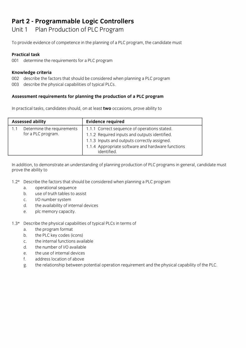
Part 2 - Programmable Logic Controllers Unit 1 Plan Production of PLC Program To provide evidence of competence in the planning of a PLC program, the candidate must Practical task 001 determine the requirements for a PLC program Knowledge criteria 002 describe the factors that should be considered when planning a PLC program 003 describe the physical capabilities of typical PLCs. Assessment requirements for planning the production of a PLC program In practical tasks, candidates should, on at least two occasions, prove ability to
Assessed ability Evidence required
1.1 Determine the requirements for a PLC program.
1.1.1 Correct sequence of operations stated. 1.1.2 Required inputs and outputs identified. 1.1.3 Inputs and outputs correctly assigned. 1.1.4 Appropriate software and hardware functions identified.
In addition, to demonstrate an understanding of planning production of PLC programs in general, candidate must prove the ability to 1.2* Describe the factors that should be considered when planning a PLC program
a. operational sequence b. use of truth tables to assist c. I/O number system d. the availability of internal devices e. plc memory capacity.
1.3* Describe the physical capabilities of typical PLCs in terms of
a. the program format b. the PLC key codes (icons) c. the internal functions available d. the number of I/O available e. the use of internal devices f. address location of above g. the relationship between potential operation requirement and the physical capability of the PLC.

Part 2 - Programmable Logic Controllers Unit 2 Write and Prove Program To provide evidence of competence in the writing and proving of a program, the candidate must Practical task 001 write a PLC program 002 test and edit a PLC program Knowledge criteria 003 state the software functions found in industrial PLC programs 004 state the range of PLC advanced functions available 005 state methods used to aid the development of PLC programs 006 describe methods of testing and debugging hardware and software. Practical assessment requirements for writing and proving PLC programs The candidate should, on at least one occasion, carry out each of the following tasks a. produce an industrial PLC control program incorporating PLC advanced functions using all the I/O modules of
the PLC b. modify an existing PLC program to incorporate specified changes in the control process and prove ability to
Assessed ability Evidence required
2.1 Write a PLC program
2.1.1 Instructions arranged to suit plc requirements. 2.1.2 Adequate use made of advanced functions. 2.1.3 Adequate use made of development aids. 2.1.4 Program meets specification.
2.2 Test and edit a PLC program 2.2.1 Program tested using appropriate method. 2.2.2 Display error messages analysed and corrective action taken as necessary. 2.2.3 Program retested and action taken as necessary. 2.3.4 Program meets specification.
In addition, to demonstrate an understanding of writing and proving PLC programs in general, candidates must prove the ability to 2.3* State the software functions found in industrial PLC programs
a. comparison b. logic operations c. add, subtract, multiply and divide d. binary to BCD and BCD to binary conversion.
2.4* State the range of PLC advanced functions available
a. shift register b. data register c. function blocks.

2.5* State the methods available to aid the development of programs
a. flow charts b. algorithm c. truth tables d. Boolean statements e. logic diagrams.
2.6* Describe methods of testing and debugging hardware and software
a. force outputs with PC in stop b. force input, outputs, relays, timers, counters and data with PC in run c. change data in timers, counters etc with PC in run d. use of directory of inputs, outputs, internal relays, timers, counters etc e. use of self-test and diagnostic software packages (off-line) f. analyse displayed error messages and take appropriate corrective action g. compare the contents of EPROM tape and disk stored programs with the corresponding master
programs stored in RAM.
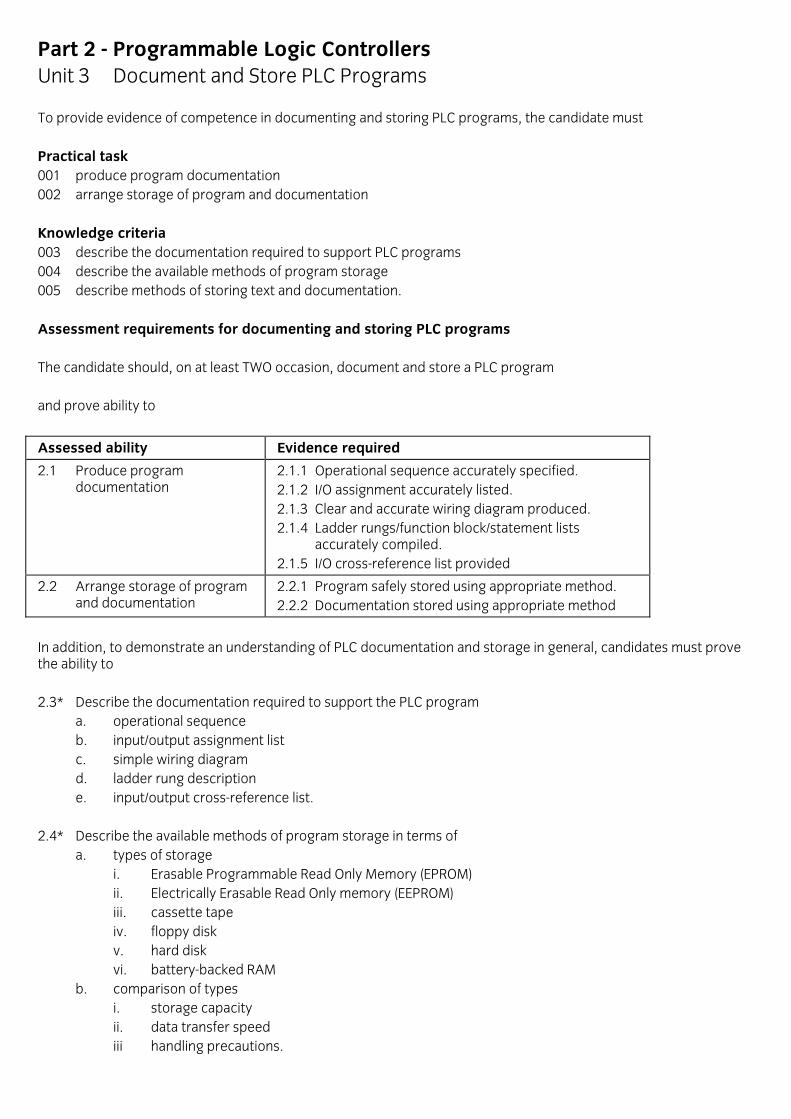
Part 2 - Programmable Logic Controllers Unit 3 Document and Store PLC Programs To provide evidence of competence in documenting and storing PLC programs, the candidate must Practical task 001 produce program documentation 002 arrange storage of program and documentation Knowledge criteria 003 describe the documentation required to support PLC programs 004 describe the available methods of program storage 005 describe methods of storing text and documentation. Assessment requirements for documenting and storing PLC programs The candidate should, on at least TWO occasion, document and store a PLC program and prove ability to
Assessed ability Evidence required
2.1 Produce program documentation
2.1.1 Operational sequence accurately specified. 2.1.2 I/O assignment accurately listed. 2.1.3 Clear and accurate wiring diagram produced. 2.1.4 Ladder rungs/function block/statement lists accurately compiled. 2.1.5 I/O cross-reference list provided
2.2 Arrange storage of program and documentation
2.2.1 Program safely stored using appropriate method. 2.2.2 Documentation stored using appropriate method
In addition, to demonstrate an understanding of PLC documentation and storage in general, candidates must prove the ability to 2.3* Describe the documentation required to support the PLC program
a. operational sequence b. input/output assignment list c. simple wiring diagram d. ladder rung description e. input/output cross-reference list.
2.4* Describe the available methods of program storage in terms of a. types of storage i. Erasable Programmable Read Only Memory (EPROM) ii. Electrically Erasable Read Only memory (EEPROM) iii. cassette tape iv. floppy disk v. hard disk vi. battery-backed RAM b. comparison of types i. storage capacity ii. data transfer speed iii handling precautions.

2.5* Describe methods of storing text and documentation
a. contact labels b. rung numbers and comments c. program text d. password implementation e. title block setting f. various printing methods g. screen dump h. program listing with and without text i. cross reference facilities.
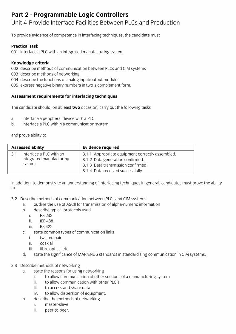
Part 2 - Programmable Logic Controllers Unit 4 Provide Interface Facilities Between PLCs and Production To provide evidence of competence in interfacing techniques, the candidate must Practical task 001 interface a PLC with an integrated manufacturing system Knowledge criteria 002 describe methods of communication between PLCs and CIM systems 003 describe methods of networking 004 describe the functions of analog input/output modules 005 express negative binary numbers in two's complement form. Assessment requirements for interfacing techniques The candidate should, on at least two occasion, carry out the following tasks a. interface a peripheral device with a PLC b. interface a PLC within a communication system and prove ability to
Assessed ability Evidence required
3.1 Interface a PLC with an integrated manufacturing system
3.1.1 Appropriate equipment correctly assembled. 3.1.2 Data generation confirmed. 3.1.3 Data transmission confirmed. 3.1.4 Data received successfully
In addition, to demonstrate an understanding of interfacing techniques in general, candidates must prove the ability to 3.2 Describe methods of communication between PLCs and CIM systems
a. outline the use of ASCII for transmission of alpha-numeric information b. describe typical protocols used
i. RS 232 ii. IEE 488 iii. RS 422
c. state common types of communication links i. twisted pair ii. coaxial iii. fibre optics, etc
d. state the significance of MAP/ENUG standards in standardising communication in CIM systems. 3.3 Describe methods of networking
a. state the reasons for using networking i. to allow communication of other sections of a manufacturing system ii. to allow communication with other PLC's iii. to access and share data iv. to allow dispersion of equipment.
b. describe the methods of networking i. master-slave ii. peer-to-peer.

3.4 Describe the functions of analog input/output modules in terms of
a. analog and digital signals b. the values of industry standard voltage and current input/output signals c. the relationship between analog inputs and outputs to word length d. the significance of positive and negative analog signals.
3.5 Express negative binary numbers in two's complement form.

This page is intentionally blank

Level 2, 3 & 4 Certificate in Computer-aided Engineering Competences (2303)
Part 3 – Computer-aided Engineering Version 1.0

Part 3 - Advanced Part Programming
Introduction This scheme is aimed at personnel who have completed a conventional vocational education and training in product manufacture (or who have a sound industrial grounding) and who have some experience of the programming and operation of CNC machines. The scheme is intended to enable students to
• evaluate component design for its suitability for CNC manufacture
• plan and manually program the efficient CNC manufacture of "relatively complex" components
• compare different methods of Computer-Aided Part Programming (CAP)
• demonstrate a competence in the use of a CAP system for the manufacture of "relatively simple" components
• be aware of developments in the application of advanced technology to manufacturing. An indication of what is meant by "relatively simple" or "relatively complex" is given in the guide notes for project work at Appendix A of this scheme. The basic requirements for candidate registrations at this level are at least 1 CAD system and at least 2 industrial machine tools.
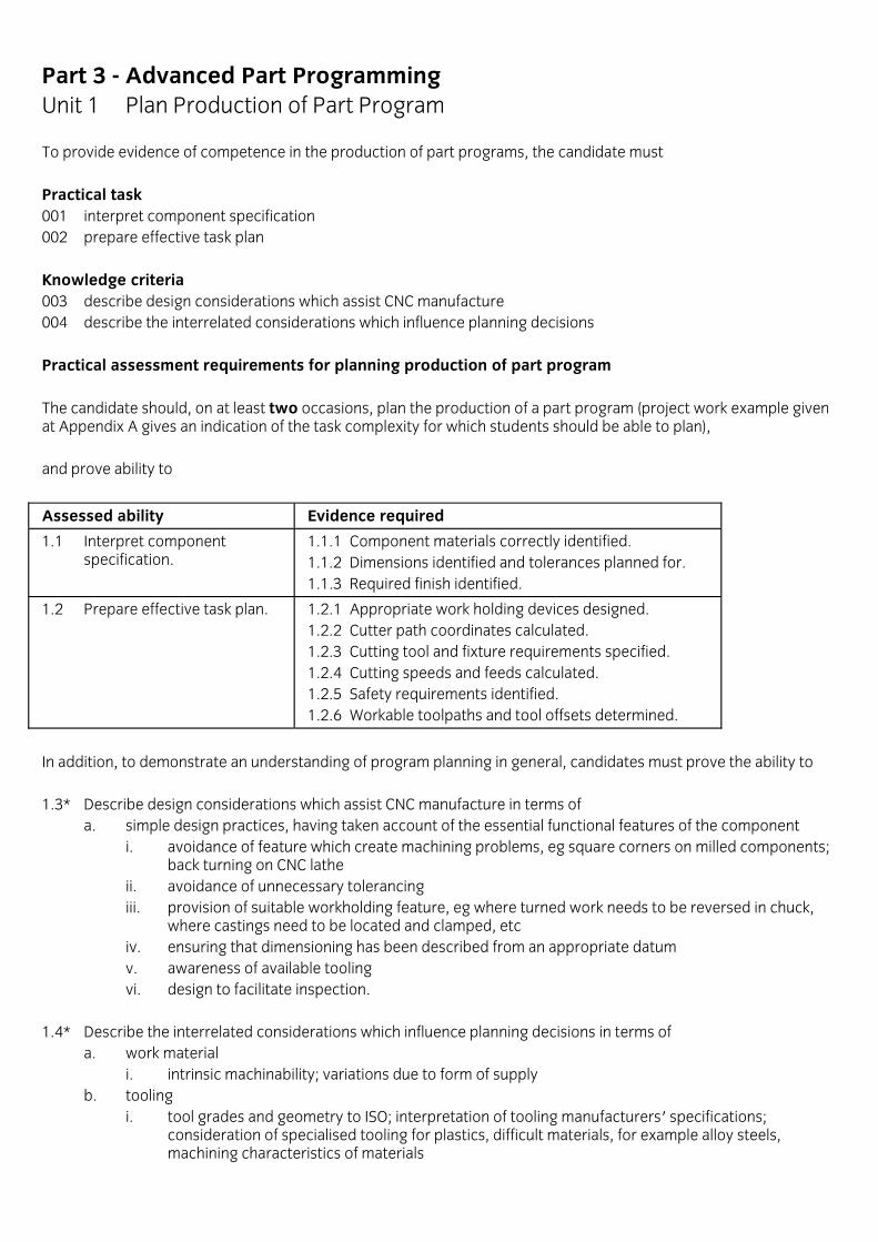
Part 3 - Advanced Part Programming Unit 1 Plan Production of Part Program To provide evidence of competence in the production of part programs, the candidate must Practical task 001 interpret component specification 002 prepare effective task plan Knowledge criteria 003 describe design considerations which assist CNC manufacture 004 describe the interrelated considerations which influence planning decisions Practical assessment requirements for planning production of part program The candidate should, on at least two occasions, plan the production of a part program (project work example given at Appendix A gives an indication of the task complexity for which students should be able to plan), and prove ability to
Assessed ability Evidence required
1.1 Interpret component specification.
1.1.1 Component materials correctly identified. 1.1.2 Dimensions identified and tolerances planned for. 1.1.3 Required finish identified.
1.2 Prepare effective task plan. 1.2.1 Appropriate work holding devices designed. 1.2.2 Cutter path coordinates calculated. 1.2.3 Cutting tool and fixture requirements specified. 1.2.4 Cutting speeds and feeds calculated. 1.2.5 Safety requirements identified. 1.2.6 Workable toolpaths and tool offsets determined.
In addition, to demonstrate an understanding of program planning in general, candidates must prove the ability to 1.3* Describe design considerations which assist CNC manufacture in terms of
a. simple design practices, having taken account of the essential functional features of the component i. avoidance of feature which create machining problems, eg square corners on milled components;
back turning on CNC lathe ii. avoidance of unnecessary tolerancing iii. provision of suitable workholding feature, eg where turned work needs to be reversed in chuck,
where castings need to be located and clamped, etc iv. ensuring that dimensioning has been described from an appropriate datum v. awareness of available tooling vi. design to facilitate inspection.
1.4* Describe the interrelated considerations which influence planning decisions in terms of
a. work material i. intrinsic machinability; variations due to form of supply
b. tooling i. tool grades and geometry to ISO; interpretation of tooling manufacturers' specifications;
consideration of specialised tooling for plastics, difficult materials, for example alloy steels, machining characteristics of materials

ii. fixture design and layout for single and multiple setups; layouts to ensure collision free operation; use of safe zones
iii. tooling requirements for variable batch manufacture; positioning of tools in magazine; tool library, its inherent limitations; balancing tool usage to optimise tool life
c. operating sequencing i. principles of operation sequencing to minimise number of workholding and tool changes
d. speeds and feeds i. optimisation of cutting conditions (taking account of component configuration); comparative
material removal rates and power consumption for roughing and surface finishing operations; relationship of speed and feed rate, depth of cut and tool life
e. in process gauging i. feedback to the control system affecting toolset, tool breakage.
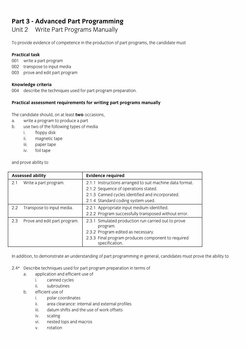
Part 3 - Advanced Part Programming Unit 2 Write Part Programs Manually To provide evidence of competence in the production of part programs, the candidate must Practical task 001 write a part program 002 transpose to input media 003 prove and edit part program Knowledge criteria 004 describe the techniques used for part program preparation. Practical assessment requirements for writing part programs manually The candidate should, on at least two occasions, a. write a program to produce a part b. use two of the following types of media i. floppy disk ii. magnetic tape iii. paper tape iv. foil tape and prove ability to
Assessed ability Evidence required
2.1 Write a part program. 2.1.1 Instructions arranged to suit machine data format. 2.1.2 Sequence of operations stated. 2.1.3 Canned cycles identified and incorporated. 2.1.4 Standard coding system used.
2.2 Transpose to input media. 2.2.1 Appropriate input medium identified. 2.2.2 Program successfully transposed without error.
2.3 Prove and edit part program. 2.3.1 Simulated production run carried out to prove program. 2.3.2 Program edited as necessary. 2.3.3 Final program produces component to required specification.
In addition, to demonstrate an understanding of part programming in general, candidates must prove the ability to 2.4* Describe techniques used for part program preparation in terms of
a. application and efficient use of i. canned cycles ii. subroutines
b. efficient use of i. polar coordinates ii. area clearance: internal and external profiles iii. datum shifts and the use of work offsets iv. scaling vi. nested lops and macros v. rotation

vi. mirror imaging c. the generation of sub-routines to supplement existing canned cycles d. the use of variables (parametrics) for machining families of parts e. consideration of programming requirements for fourth axis work f. tool nose radius compensation (TNRC) for complex contours; review of cutter diameter compensation.
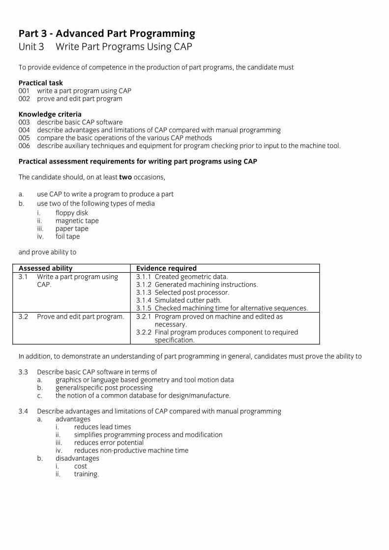
Part 3 - Advanced Part Programming Unit 3 Write Part Programs Using CAP To provide evidence of competence in the production of part programs, the candidate must Practical task 001 write a part program using CAP 002 prove and edit part program Knowledge criteria 003 describe basic CAP software 004 describe advantages and limitations of CAP compared with manual programming 005 compare the basic operations of the various CAP methods 006 describe auxiliary techniques and equipment for program checking prior to input to the machine tool. Practical assessment requirements for writing part programs using CAP The candidate should, on at least two occasions, a. use CAP to write a program to produce a part b. use two of the following types of media i. floppy disk ii. magnetic tape iii. paper tape iv. foil tape and prove ability to Assessed ability Evidence required 3.1 Write a part program using CAP.
3.1.1 Created geometric data. 3.1.2 Generated machining instructions. 3.1.3 Selected post processor. 3.1.4 Simulated cutter path. 3.1.5 Checked machining time for alternative sequences.
3.2 Prove and edit part program. 3.2.1 Program proved on machine and edited as necessary. 3.2.2 Final program produces component to required specification.
In addition, to demonstrate an understanding of part programming in general, candidates must prove the ability to 3.3 Describe basic CAP software in terms of
a. graphics or language based geometry and tool motion data b. general/specific post processing c. the notion of a common database for design/manufacture.
3.4 Describe advantages and limitations of CAP compared with manual programming
a. advantages i. reduces lead times ii. simplifies programming process and modification iii. reduces error potential iv. reduces non-productive machine time
b. disadvantages i. cost ii. training.

3.5 Compare the basic operations of the various CAP methods in terms of a. techniques i. general distinctions A. language based/interactive graphics B. tape input/direct input C. off-line/on-line ii. common language types: APT variants iii. interactive graphics types A. off-line tape preparation B. off-line direct input (basic DNC) C. on-line MDI (conversational programming) b. applications, advantages, limitations. 3.6 Describe auxiliary techniques and equipment for program checking prior to input to the machine tool
a. software/hardware/verification facilities for i) simulation/tape validation ii) toolpath plotting iii) programming diagnostics.
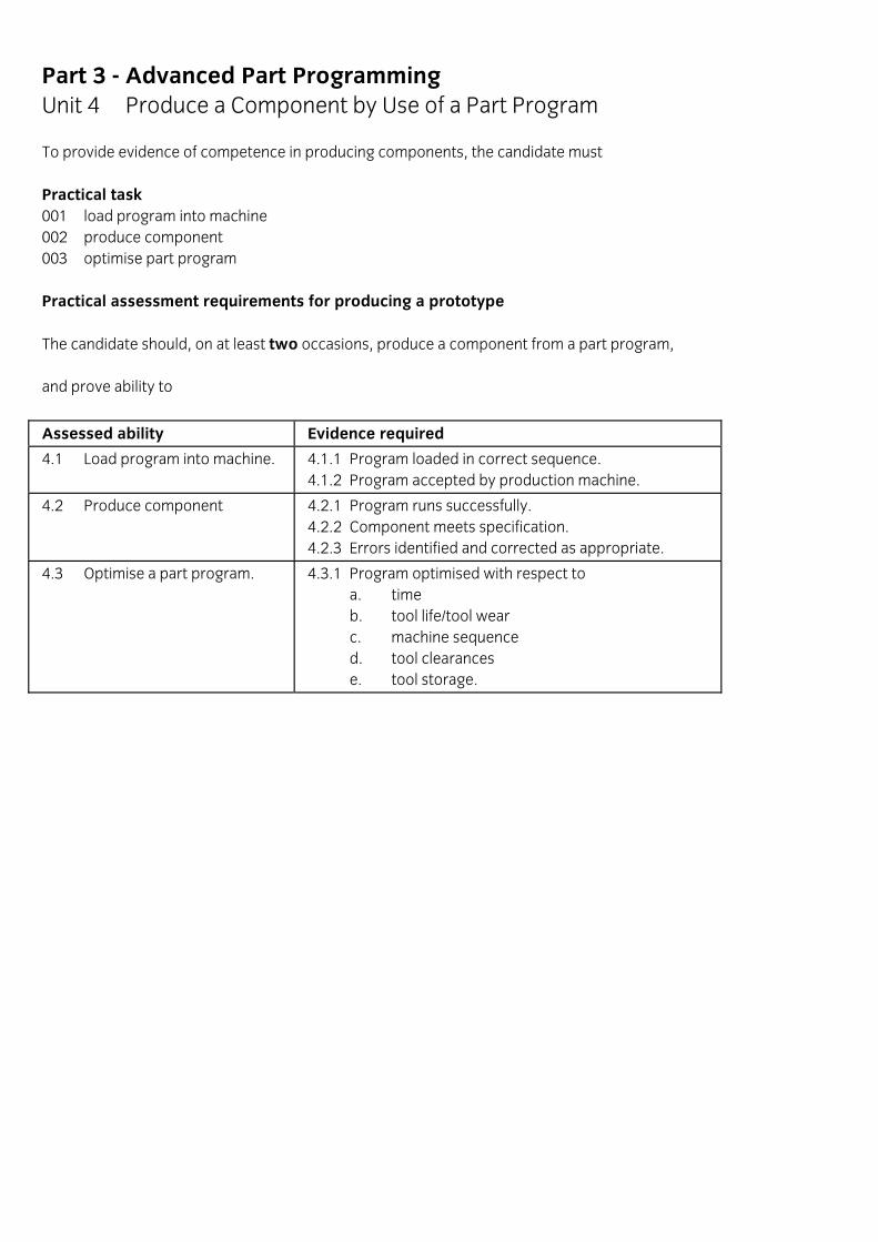
Part 3 - Advanced Part Programming Unit 4 Produce a Component by Use of a Part Program To provide evidence of competence in producing components, the candidate must Practical task 001 load program into machine 002 produce component 003 optimise part program Practical assessment requirements for producing a prototype The candidate should, on at least two occasions, produce a component from a part program, and prove ability to
Assessed ability Evidence required
4.1 Load program into machine. 4.1.1 Program loaded in correct sequence. 4.1.2 Program accepted by production machine.
4.2 Produce component 4.2.1 Program runs successfully. 4.2.2 Component meets specification. 4.2.3 Errors identified and corrected as appropriate.
4.3 Optimise a part program. 4.3.1 Program optimised with respect to a. time b. tool life/tool wear c. machine sequence d. tool clearances e. tool storage.
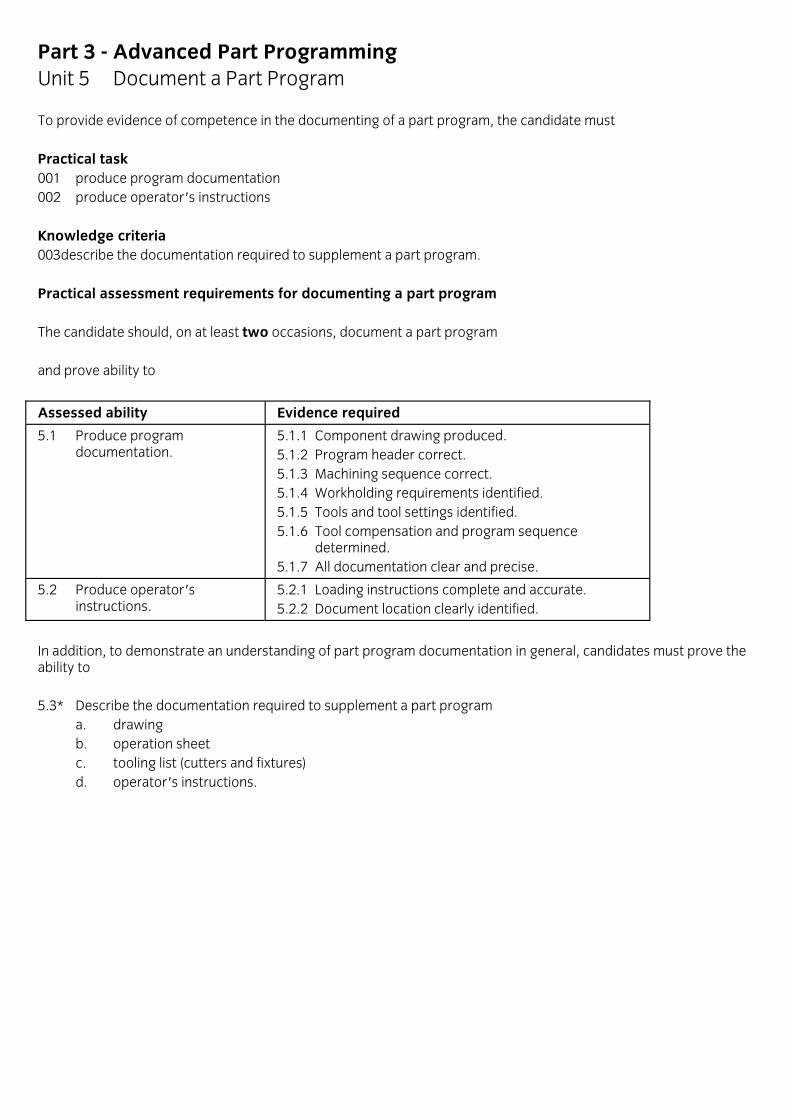
Part 3 - Advanced Part Programming Unit 5 Document a Part Program To provide evidence of competence in the documenting of a part program, the candidate must Practical task 001 produce program documentation 002 produce operator's instructions Knowledge criteria 003describe the documentation required to supplement a part program. Practical assessment requirements for documenting a part program The candidate should, on at least two occasions, document a part program and prove ability to
Assessed ability Evidence required
5.1 Produce program documentation.
5.1.1 Component drawing produced. 5.1.2 Program header correct. 5.1.3 Machining sequence correct. 5.1.4 Workholding requirements identified. 5.1.5 Tools and tool settings identified. 5.1.6 Tool compensation and program sequence determined. 5.1.7 All documentation clear and precise.
5.2 Produce operator's instructions.
5.2.1 Loading instructions complete and accurate. 5.2.2 Document location clearly identified.
In addition, to demonstrate an understanding of part program documentation in general, candidates must prove the ability to 5.3* Describe the documentation required to supplement a part program
a. drawing b. operation sheet c. tooling list (cutters and fixtures) d. operator's instructions.
Part 3 - Advanced Part Programming Unit 6 Computer Integrated Manufacture To provide evidence of attainment in computer integrated manufacture, the candidate must Knowledge criteria 001 describe the basic flow of technical and management information within a typical production system 002 describe the principles of computer-aided engineering (CAE) 003 describe what is meant by database 004 describe the basis of automated flexible manufacture 005 describe the use of robots in computer-integrated manufacture 006 describe the application of computer control to the inspection process. Assessment requirements for computer integrated manufacture To demonstrate an understanding of computer integrated manufacture in general, candidates must prove ability to 6.1 Describe the basic flow of technical and management information within a typical production system in terms of
a. production system i. marketing ii. design iii. draughting iv. manufacture v. inspection and testing vi. assembly vii. livery
b. relationship of planning, costing and inventory control. 6.2 Describe the principles of computer-aided engineering
a. define terms associated with CAM i. CNC ii. CAP iii. DNC
b. state the relationship between computer-aided design and computer-aided draughting c. describe the integration of CAD with CAM in terms of
i. how a CAD/CAM system stores geometry ii. how additional dimensional information enables the production of a component drawing iii. how tool motion data enables the production of a part program iv. importance of CAP as technical link v. DNC as gateway for management information vi. progressive integration of technical and management information towards computer-integrated
manufacture (CIM) d. state the relationship between data storage requirements for the processes listed in a) to c) and levels of
computer hardware i. mainframe ii. mini iii. micro iv. dedicated
e. state the problems associated with computer-integrated or individually controlled machines and equipment.
6.3 Describe what is meant by database in terms of
a. its role in system integration b. the problems of integrating/interfacing peripherals and individually controlled machines in terms of
compatibility of i. hardware/hardware ii. hardware/software iii. software/software. 6.4 Describe the basis of automated flexible manufacture in terms of
a. what is meant by a flexible manufacturing system (FMS) b. application of FMS to batch production c. notion of families of parts
i. by type ii. by size iii. by assembly iv. by process
d. basic FMS requirements for integrated computer control of i. process machinery ii. work loading iii. location iv. holding v. transfer vi. tool changing vii. materials handling
e. the use of robots f. advantages of FMS
i. rapid response ii. reduced lead times iii. minimum inventory iv. lower unit costs v. freedom from constraints of batch sizes. 6.5 Describe the use of robots in computer aided manufacture in terms of a. basic robot types b. technical, social and economic considerations i. increased productivity ii. improved product quality iii. operational flexibility iv. function in hostile environment v. relief of boredom c. applications i. palletising ii. machine loading iii. tool changing iv. interstage loading v. deburring vi. parts assembly.

6.6 Describe the application of computer control to the inspection process in terms of a. application of computer control to in-process and post-process inspection b. benefits
i. integrated in-process feedback ii. rapid information generation for shape and statistical analysis
c. types of equipment and applications i. contact types ii. calipers, probes iii. non-contact types iv. vision systems
d. interfacing with adaptive control.

APPENDIX A
NC/CNC Advanced Part Programming
Guidelines for practical work
Introduction The project aims to draw together the various aspects of the scheme to show clearly how the content relates to industrial practice, and will provide a common measure of student ability to undertake realistic tasks. It has been suggested in the body of the scheme that a number of the learning objectives are likely to be accomplished during the project work and this may influence the way that teaching time is planned. As a rough guide, however, it is suggested that tutors allocate some 50% of the course to project work, and in any case not less than 30 hours. General project requirements The project comprises the preparation of two fully documented part programs for a. a "relatively complex" component, using a manual programming method b. a "relatively simple" component, using a computer-aided programming method both of which must be proven and cut on typical industrial CNC machinery. Project tasks Annexed to this appendix is a range of specimen assignments for centres to use. The selection indicates what is implied by relatively complex and relatively simple, and aims to present a variety of planning and programming problems. They are offered as a guide only, however, as it is envisaged that tutors will want to involve students' employers in the choice or formulation of project work. Care should be taken, however, to ensure that alternative tasks are of an equivalent complexity, and where any doubt exists reference should be made to City and Guilds before proceeding.
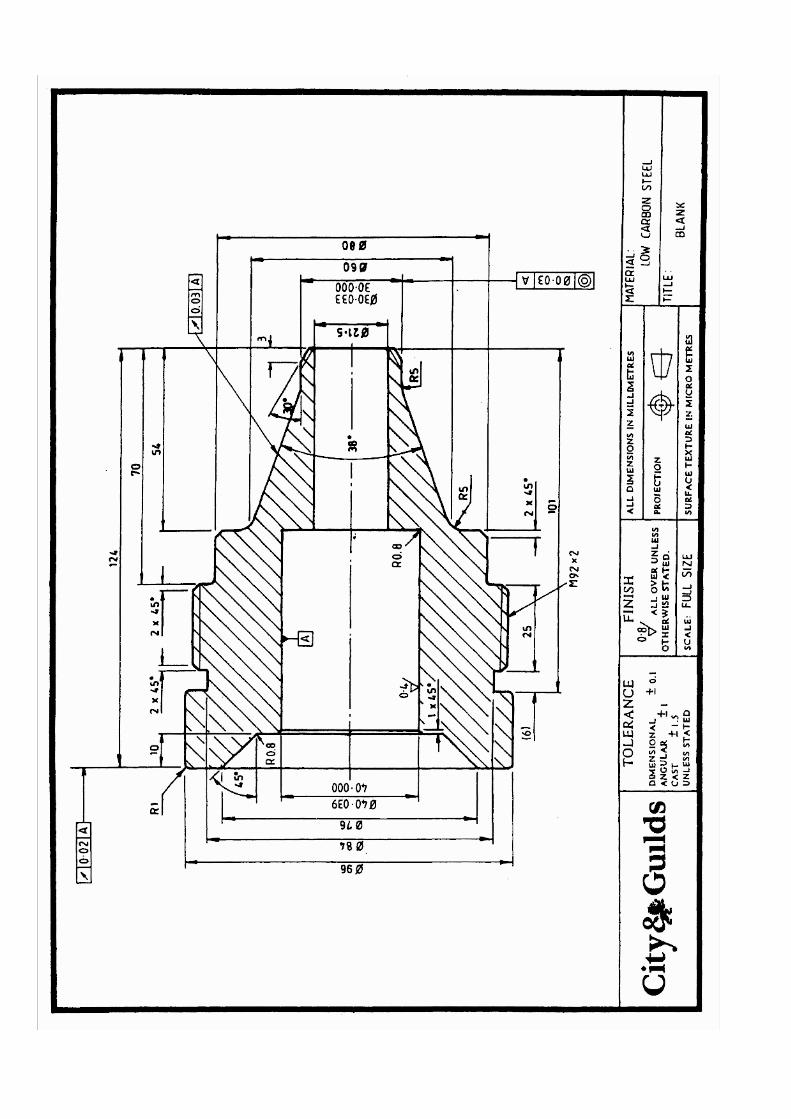
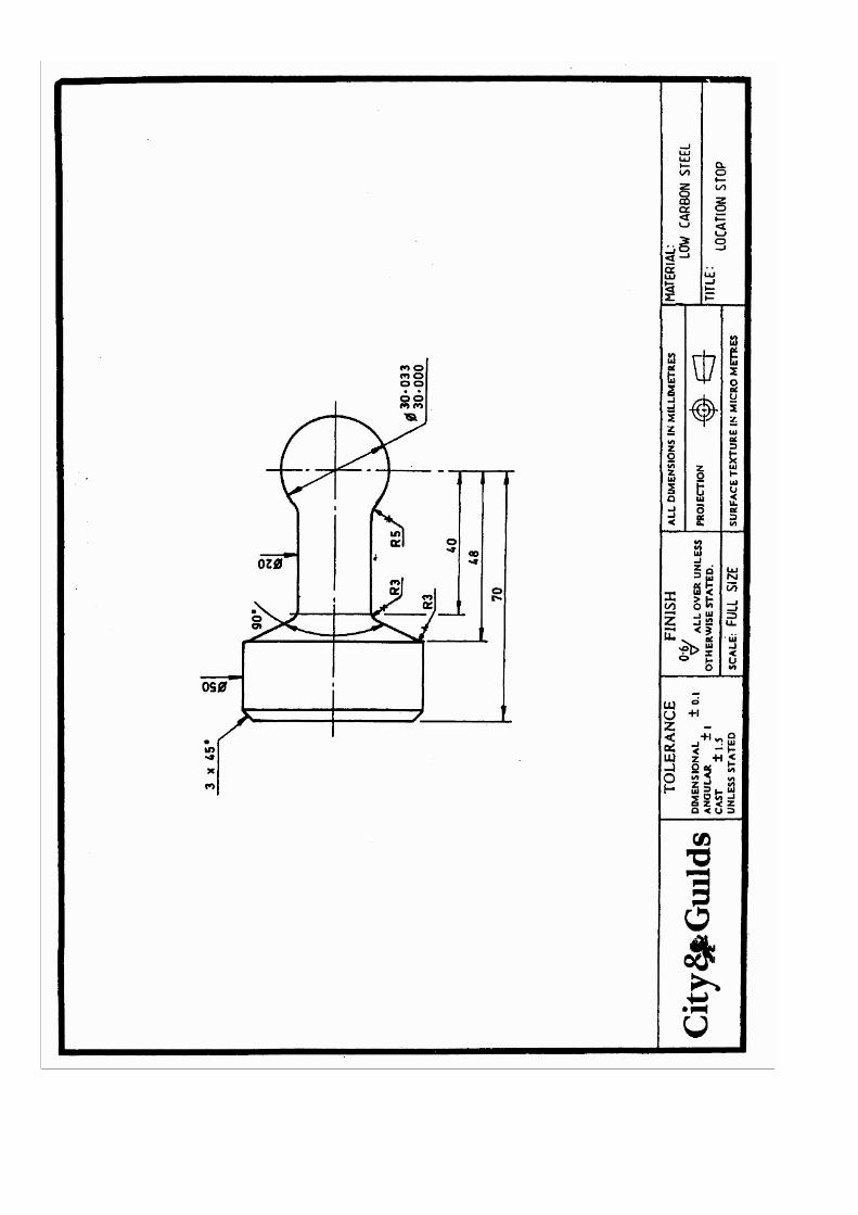
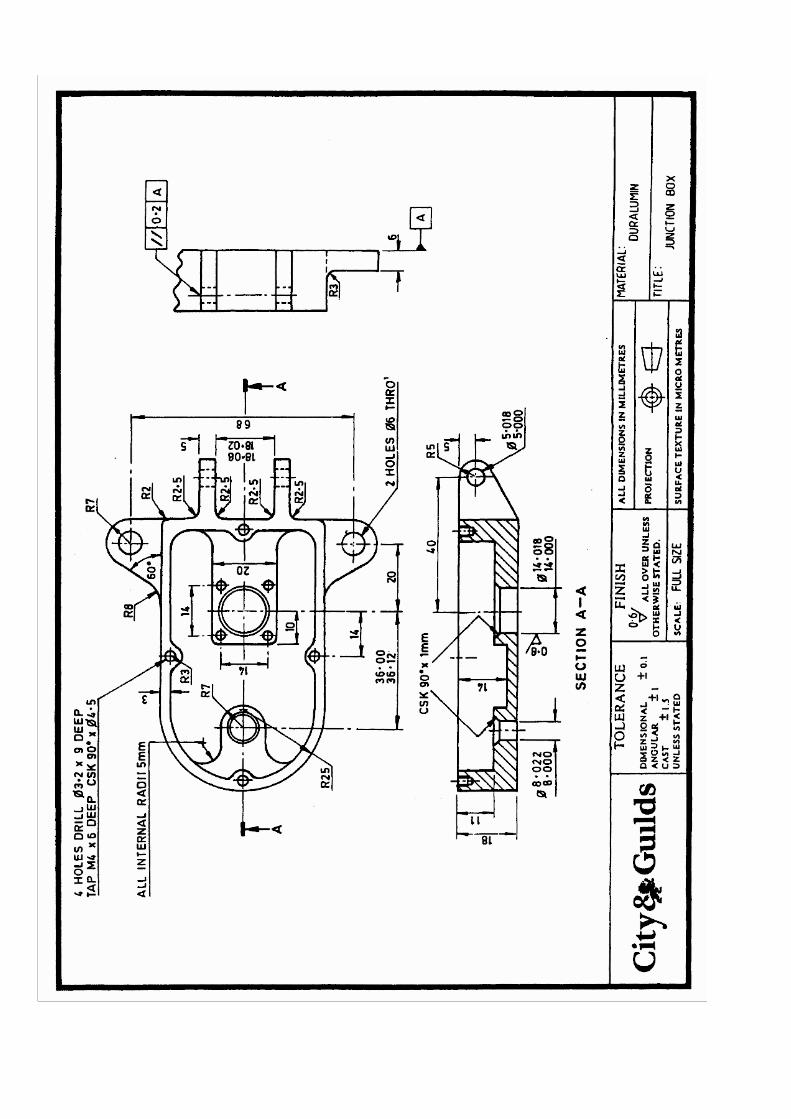
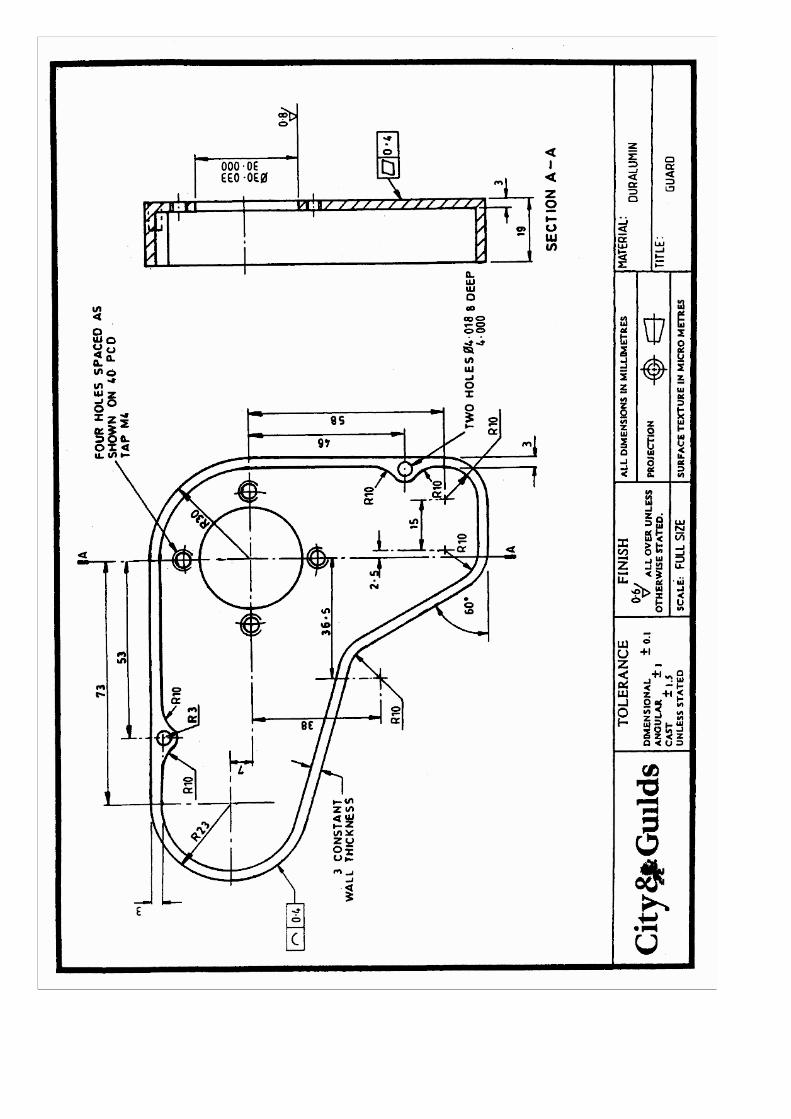
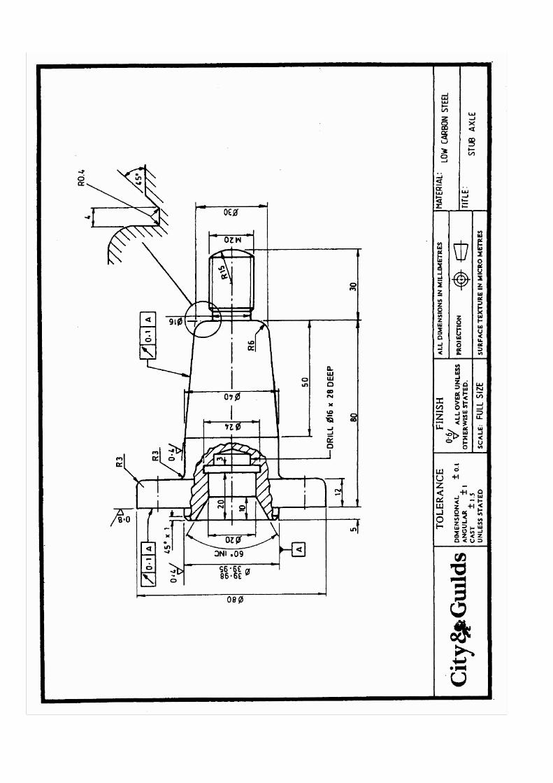
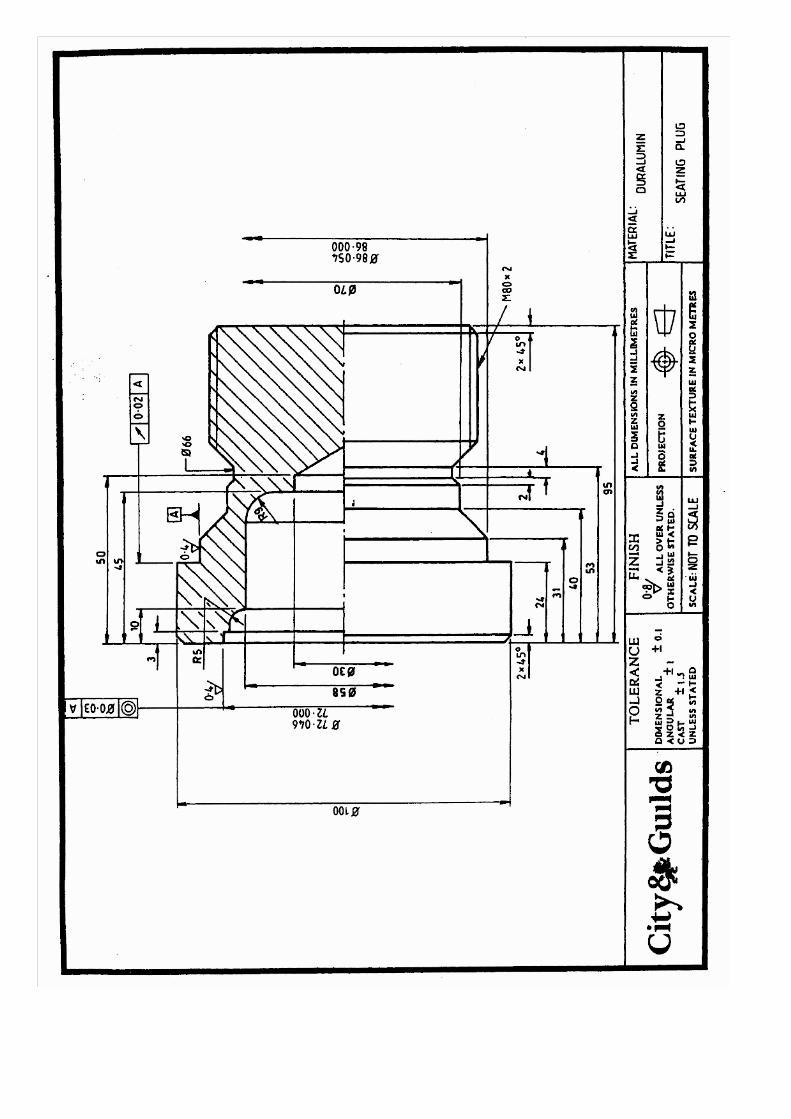
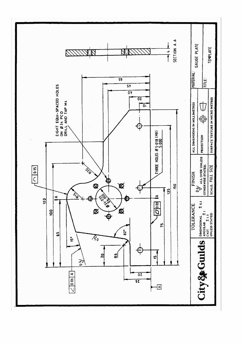
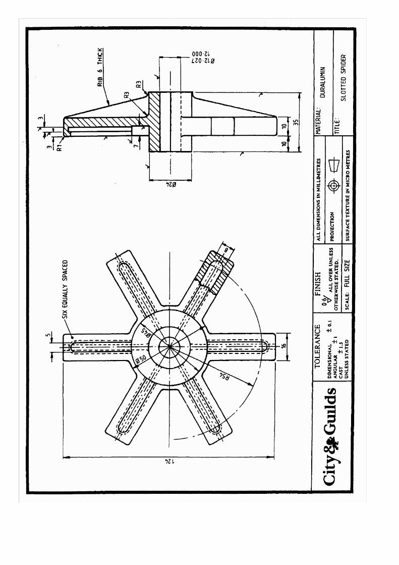
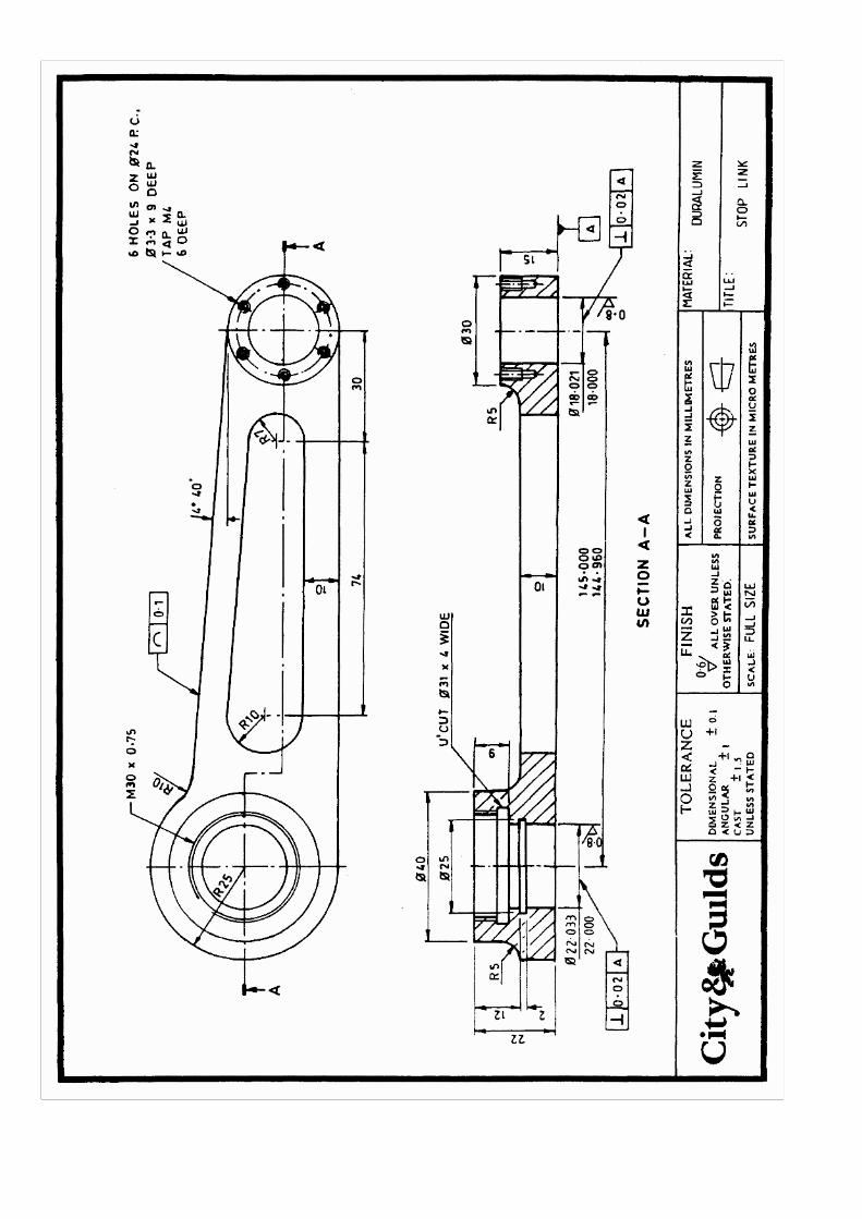
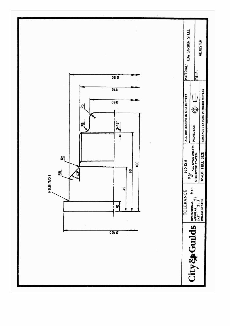

Part 3 - Advanced Computer-aided Draughting and Design
Introduction This scheme is designed primarily for those preparing to assume some form of responsibility for the computer-aided engineering process. Students are expected to have reached a level of competence in computer-aided engineering techniques consistent with the 230 Part 2 scheme. The aim is to extend existing CAE expertise to take into account the entire system for CAE and to develop skills in the use of computer-aided design analysis for various applications. Guidance Notes on Advanced Computer-aided Draughting and Design a. The scheme is aimed at personnel who have achieved a level of competence in the use of a computer-aided
draughting system and wish to extend their knowledge of such systems and design analysis. i. To evaluate the capabilities of at least two CAD systems. ii. To configure CAD system hardware and software. iii. To utilise hardware and software methods of enhancing system performance. iv. To utilise 3D graphics software for basic design and analysis purposes. v. Extract data for the production of 'bills of materials'.
b. The scheme has a strong practical focus to it and the emphasis of time available to "hands on" activity. Tutors should aim to devise practical work which, as far as possible, utilise the advanced facilities of CAD systems and are industrially relevant. Practical Assessment It is recommended that project work consist of a student devised central scheme incorporating a number of the factors/tasks (at least four) shown below. The work undertaken should be relevant to the students employment ie. related to industrial practice. The project should incorporate at least one 'non CAD' activity. Typical examples of the range of project work are given below. The factors are 1. The production of a 3D wire frame drawing, surface modelled. 2. The preparation of detailed drawings from a surface model. 3. The FEA of a detiled part. 4. Customising menus and creating macros for use in CAD. 5. The production of an assembly drawing, or an exploded view. 6. The automatic extraction of drawing data for a BOM. 7. The transfer of geometrical data for CAM. 8. The use of CAM software to produce the part program. 9. The simulation of the above prior to machining. 10. The transfer of drawings between different systems. 11. The use of customising software such as CADL or LISP programs. 12. The use of the operating system to manage files and carry out good house-keeping practices. 13. Report preparation. At all times the work should reflect industrial standards and utilise industrially based equipment. No sample project work is given in this instance since there is a wide choice of project material which should enable all centres offering the scheme to match project work to centre resources and expertise.

Part 3 - Advanced Computer-aided Draughting and Design Unit 1 Interchange Data To provide evidence of competence in data interchange, the candidate must Practical tasks 001 interpret transmission data protocol to correct standards Knowledge criteria 002 state how the interfacing of systems is achieved 003 describe the importance of the CAD data base within a computer-integrated manufacturing system 004 state the factors to be considered with respect to power and flexibility for use within computer aided engineering environments. Practical assessment requirements for data interchange Range The candidate should, on at least two occasions, interchange data and prove ability to
Assessed ability Evidence required
1.1 Interpret transmission data protocol to correct standards.
1.1.1 Selected equipment to correct standards 1.1.2 Selected correct protocol standards and values. 1.1.3 Transferred data from one system to another.
In addition, to demonstrate an understanding of data interchange, candidates must prove ability to 1.2 State how the interfacing of systems is achieved
a. data transfer via computer links/networks, serial and parallel interfaces b. use of IGES and DXF file interchange systems
1.3 Describe the importance of the CAD database within a computer-integrated manufacturing system
a. use of the CAD database with the following software packages i. component analysis ii. bills of materials iii. manufacture iv. stock control v. purchasing vi. despatch
b. type of data transferred from package to package. 1.4 State the factors to be considered with respect to power and flexibility for use within computer aided engineering environments a. processing capability b. storage c. communications and flexibility for 3D systems and finite element d. cost of systems with respect to application and use.

Part 3 - Advanced Computer-aided Draughting and Design Unit 2 Maintain a Computer System To provide evidence of competence in the maintenance of computer systems, the candidate must Practical tasks 001 use operating system and perform file management activities Knowledge criteria 002 describe the operating system requirements of systems used within a CAD environment 003 state good practice with regard to the organisation of the CAD database 004 state the methods of improving a CAD system performance by the use of hardware enhancements. Practical assessment requirements for the maintenance of a computer system. The candidate should, on at least two occasions, maintain a computer system and prove ability to
Assessed ability Evidence required
2.1 Use operating system and perform file management activities.
2.1.1 Files, programs and data are successfully a. loaded b. retrieved c. updated d. created e. transferred using the operating system. 2.1.2 Files, programs and data successfully transferred using application software 2.1.3 Batch files successfully created. 2.1.4 Accurate data back-up produced.
In addition, to demonstrate an understanding of the maintenance of a computer system, candidates must prove the ability to 2.2 Describe the main features of the following operating systems a. UNIX b. DRDOS c. OS2. 2.3 Describe good practice with regard to the organisation of the CAD database in terms of
a. file handling, security and efficiency b. functions of a database management system c. use of back-ups.
2.4 State the methods of improving a CAD system performance by the use of hardware enhancements a. increased RAM b. hard disks c. mathematics co-processors d. graphics processors e. increase main processor speed.

Part 3 - Advanced Computer-aided Draughting and Design Unit 3 Produce Drawings, Macros and Menus on a CAD System To provide evidence of competence in the production of drawings, macros and menus, the candidate must Practical tasks 001 produce drawings using CAD software 002 produce macros and menus for a CAD system Knowledge criteria 003 state the common commands used to create geometry and allied data 004 describe the advanced function capabilities of CAD systems 005 describe the menu creation capabilities of CAD systems 006 compare a CAD system with conventional drawing techniques. Assessment requirements for the production of drawings, macros and menus The candidate should, on at least two occasions, carry out the following tasks a. produce a 3D drawing of a component b. produce a 2D drawing of a complex component c. produce a macros/menu and thus prove ability to
Assessed ability Evidence required
3.1 Produce drawings using CAD software.
3.1.1 Complex 2D drawing produced 3.1.2 3D Wire frame drawing produced 3.1.3 Surface modelled drawing produced
3.2 Produce macros and menus for a CAD system.
3.2.1 Macro/menu meet specified requirements. 3.2.2 Macro/menu can be followed easily.
In addition, to demonstrate an understanding of the production of drawings, macros and menus in general, candidates must prove the ability to 3.3 State the common commands used to create geometry and allied data commands for a. production and manipulation of geometry b. dimensions c. text and associated entity data. 3.4 Describe the advanced function capabilities of CAD systems in terms of
a. maximising production of drawings using i. text file ii. macros iii. parametrics iv. system variables v. sub-routines
b. creating extended geometry capabilities i. use of macros to produce polygons, ellipses.
3.5 Describe the menu creation capabilities of CAD systems for

a. standard geometry/component b. parametric and repetition geometry c. sub-routines and customisation
3.6 Compare a CAD system with conventional draughting techniques in terms of a. speed of creation b. checking and editing c. memory facility d. quality of finished drawing e. storage space f. cost.

Part 3 - Advanced Computer-aided Draughting and Design Unit 4 Computer Modelling To provide evidence of competence in computer modelling, the candidate must Practical tasks 001 produce a computer model on a CAD system 002 test validity of CAD models Knowledge criteria 003 state the advantages and limitations of common types of model 004 describe methods of analysis by the mass properties technique 005 describe coordinate systems used in modelling 006 describe how design packages are used with a CAD system production. Assessment requirements for computer modelling The candidate should on at least one occasion, carry out the following tasks a. construct a complex frame model with hidden line removal b. construct a complex solid model c. test validity of model by computer data produced using mass properties techniques wit the properties
measured from physical component and thus prove ability to
Assessed ability Evidence required
4.1 Produce a computer model on a CAD system.
4.1.1 Model produced using appropriate commands. 4.1.2 Model met required specification.
4.2 Test validity of CAD models. 4.2.1 Property analysed is appropriate to type of model. 4.2.2 Analysis carried out accurately and in an efficient manner. 4.2.3 Amendments made to model based on analysis.
In addition, to demonstrate an understanding of computer modelling in general, candidates must provide the ability to 4.3 State the advantages and limitations of common types of model
a. wire frame b. wire frame with hidden line removal c. surface model d. solid model.
4.4 Describe methods of analysis by the mass properties technique
e. volume f. surface g. centroids and moments of area.
4.5 Describe co-ordinate systems used in modelling

a. world co-ordinate system for multiple modelling b. eye point co-ordinates for viewing
i. static viewing ii. dynamic viewing.
4.6 Describe how design packages are used with a CAD system production in terms of
a. analysis packages i. finite element ii. PCB design simulation iii. kinematic representation iv. collision checking
b. reliability of data produced and factors that affect accuracy c. input requirements of analytical systems and required input devices d. information produced by analytical systems and required output devices.

Published by City & Guilds 1 Giltspur Street London EC1A 9DD T +44 (0)20 7294 2800 F +44 (0)20 7294 2400 www.cityandguilds.com City & Guilds is a registered charity established to promote education and training