Embed Size (px)
Citation preview

CERTIFICATENo. P15220415
Order No. 294296 Page 1/2
Date of issue 02-11-2015
Okhyun JeonCertification Department
Nemko ASGaustadalléen 30, P.O. Box 73 Blindern, 0314 Oslo, NorwayTEL +47 22 96 03 30 FAX +47 22 96 05 50 EMAIL [email protected] NUMBER NO974404532 nemko.com
Product Medical power supply for building-in
Applicant Bel Fuse Inc.206 Van Vorst St.Jersey City, NJ 07302USA
Manufacturer Bel Fuse Inc.206 Van Vorst St.Jersey City, NJ 07302USA
Factory EOS Power India PVT Ltd.Unit #57, SDF II, Seepz-Sez, Andheri (East)Mumbai 400 096India
See next page(s)
Ratings AC Input: 3.0A Max, 100-240V~, 47-63Hz
Trade mark
Model / Type Ref. MBC120-1XXXL-YYY-W
Principal characteristics Cl. I, Output: Refer to General Product InformationWhere "X" and "Y" = 0-9, A-Z, a-z or blank, W is blank for Class I
See next page(s)
A sample of the product was testedand found to be in conformity with
MED EN 60601-1:2006;A11;A1;A12
Validity This certificate documents conformity with the standards shown, and also applies as license foruse of Nemkos name and certification mark. The certificate and license is valid as long as theapplicable conditions are complied with, and provided that any changes to the product are notifiedto Nemko for acceptance prior to implementation.New standards or amendments to the standards may imply that the product design must beupdated and/or that re-testing and re-certification is necessary.
Additional information See next page(s)
The abovementioned certified equipment complies with current regulatory requirements regardingelectrical safety in Norway and other EU/EEA member states, as far as this can be checked.Compliance with requirements regarding building-in, protection against electric shock andElectromagnetic Compatibility (EMC) must be checked when the equipment is built-in a completedproduct or forms a part of a complete system.
Additional model(s) See next page(s)

CERTIFICATENo. P15220415
Order No. 294296 Page 2/2
Date of issue 02-11-2015
Okhyun JeonCertification Department
Nemko ASGaustadalléen 30, P.O. Box 73 Blindern, 0314 Oslo, NorwayTEL +47 22 96 03 30 FAX +47 22 96 05 50 EMAIL [email protected] NUMBER NO974404532 nemko.com
Product Medical power supply for building-in
Pos. No 1Model / Type Ref. MBC75-1XXXL-YYY-WTrade mark (if different from page 1) Rating AC Input: 2.0A Max, 100-240V~ 47-63HzPrincipal characteristics Cl. I, Output: Refer to General Product Information
Where "X" and "Y" = 0-9, A-Z, a-z or blank, W is blank for Class I

CERTIFICATENo. P15220406
Order No. 294298 Page 1/2
Date of issue 30-10-2015
Juan Z. KleppenesCertification Department
Nemko ASGaustadalléen 30, P.O. Box 73 Blindern, 0314 Oslo, NorwayTEL +47 22 96 03 30 FAX +47 22 96 05 50 EMAIL [email protected] NUMBER NO974404532 nemko.com
Product Medical Power Supply (for building-in)
Applicant Bel Fuse Inc.206 Van Vorst St.Jersey City, NJ 07302USA
Manufacturer Bel Fuse Inc.206 Van Vorst St.Jersey City, NJ 07302USA
Factory EOS Power India PVT Ltd.Unit #57, SDF II, Seepz-Sez, Andheri (East)Mumbai 400 096India
See next page(s)
Ratings AC Input: 3.0A Max, 100-240V~ 47-63Hz
Trade mark
Model / Type Ref. MBC120-1XXXL-YYY-2
Principal characteristics Cl. II. Output rating see the test report. The "X" and "Y" = 0-9, A-Z, a-z or blankSee next page(s)
A sample of the product was testedand found to be in conformity with
MED EN 60601-1:2006;A11;A1;A12
Validity This certificate documents conformity with the standards shown, and also applies as license foruse of Nemkos name and certification mark. The certificate and license is valid as long as theapplicable conditions are complied with, and provided that any changes to the product are notifiedto Nemko for acceptance prior to implementation.New standards or amendments to the standards may imply that the product design must beupdated and/or that re-testing and re-certification is necessary.
Additional information See next page(s)
The abovementioned certified equipment complies with current regulatory requirements regardingelectrical safety in Norway and other EU/EEA member states, as far as this can be checked.Compliance with requirements regarding building-in, protection against electric shock andElectromagnetic Compatibility (EMC) must be checked when the equipment is built-in a completedproduct or forms a part of a complete system.
Additional model(s) See next page(s)

CERTIFICATENo. P15220406
Order No. 294298 Page 2/2
Date of issue 30-10-2015
Juan Z. KleppenesCertification Department
Nemko ASGaustadalléen 30, P.O. Box 73 Blindern, 0314 Oslo, NorwayTEL +47 22 96 03 30 FAX +47 22 96 05 50 EMAIL [email protected] NUMBER NO974404532 nemko.com
Product Medical Power Supply (for building-in)
Pos. No 1Model / Type Ref. MBC75-1XXXL-YYY-2Trade mark (if different from page 1) Rating AC Input: 2.0A Max, 100-240V~ 47-63HzPrincipal characteristics Cl. II. Output rating see the test report. The "X" and "Y" = 0-9, A-Z, a-z or
blank

Ref. Certif. No.
NO89049
Gaustadalléen 30NO-0373 Oslo, Norway
Date: 27-10-2015 Signature: Juan Z. KleppenesCertification Department
Issued 2007-04 1/1
IEC SYSTEM FOR MUTUAL RECOGNITION OF TEST CERTIFICATES FOR ELECTRICALEQUIPMENT (IECEE) CB SCHEME
SYSTEME CEI DACCEPTATION MUTUELLE DE CERTIFICATS DESSAIS DESEQUIPEMENTS ELECTRIQUES (IECEE) METHODE OC
CB TEST CERTIFICATE CERTIFICAT D'ESSAI OC
ProductProduit Medical power supply for ( building-in )
Name and address of the applicantNom et adresse du demandeur
EOS Power India PVT Ltd.Unit #57, SDF II, Seepz-SezAndheri (East), Mumbai 400 096India
Name and address of the manufacturerNom et adresse du fabricant
EOS Power India PVT Ltd.Unit #57, SDF II, Seepz-SezAndheri (East), Mumbai 400 096India
Name and address of the factoryNom et adresse de l'usine
EOS Power India PVT Ltd.Unit #57, SDF II, Seepz-SezAndheri (East), Mumbai 400 096India
Note: When more than one factory, please report on page 2Note: Lorsque il y plus d'une usine, veuillez utiliser la deuxième page
Additional information on page 2
Ratings and principal characteristicsValeurs nominales et caractéristiques principales
AC Input: 3.0 A Max, 100- 240 V~, 47- 63 Hz, CI. I
Trademark (if any)Marque de fabrique (si elle existe)
Type of Manufacturer’s Testing Laboratories usedType de programme du laboratoire d’essais constructeur
Model / Type Ref.Ref. De type
MBC120-1XXXL-YYY-W
Additional information (if necessary may also bereported on page 2)Les informations complémentaires (si nécessaire,peuvent être indiqués sur la deuxième page
Output rating see test report. In model name, the "X" and "Y" = 0-9, A-Z, a-z or blank, W is blank for Cl. I
Additional information on page 2
A sample of the product was tested and foundto be in conformity withUn échantillon de ce produit a été essayé et a étéconsidéré conforme à la
IEC 60601-1(ed.3);am1
As shown in the Test Report Ref. No. which forms partof this CertificateComme indiqué dans le Rapport dessais numéro deréférence qui constitue partie de ce Certificat
294295
This CB Test Certificate is issued by the National Certification BodyCe Certificat dessai OC est établi par l'Organisme National de Certification

Ref. Certif. No.
NO89050
Gaustadalléen 30NO-0373 Oslo, Norway
Date: 27-10-2015 Signature: Juan Z. KleppenesCertification Department
Issued 2007-04 1/1
IEC SYSTEM FOR MUTUAL RECOGNITION OF TEST CERTIFICATES FOR ELECTRICALEQUIPMENT (IECEE) CB SCHEME
SYSTEME CEI DACCEPTATION MUTUELLE DE CERTIFICATS DESSAIS DESEQUIPEMENTS ELECTRIQUES (IECEE) METHODE OC
CB TEST CERTIFICATE CERTIFICAT D'ESSAI OC
ProductProduit Medical power supply for ( building-in )
Name and address of the applicantNom et adresse du demandeur
EOS Power India PVT Ltd.Unit #57, SDF II, Seepz-SezAndheri (East), Mumbai 400 096India
Name and address of the manufacturerNom et adresse du fabricant
EOS Power India PVT Ltd.Unit #57, SDF II, Seepz-SezAndheri (East), Mumbai 400 096India
Name and address of the factoryNom et adresse de l'usine
EOS Power India PVT Ltd.Unit #57, SDF II, Seepz-SezAndheri (East), Mumbai 400 096India
Note: When more than one factory, please report on page 2Note: Lorsque il y plus d'une usine, veuillez utiliser la deuxième page
Additional information on page 2
Ratings and principal characteristicsValeurs nominales et caractéristiques principales
AC Input: 2.0A Max 100-240V~ 47-63Hz, CI. I
Trademark (if any)Marque de fabrique (si elle existe)
Type of Manufacturer’s Testing Laboratories usedType de programme du laboratoire d’essais constructeur
Model / Type Ref.Ref. De type
MBC75-1XXXL-YYY-W
Additional information (if necessary may also bereported on page 2)Les informations complémentaires (si nécessaire,peuvent être indiqués sur la deuxième page
Output rating see test report. In model name, the "X" and "Y" = 0-9, A-Z, a-z or blank, W is blank for Cl. I
Additional information on page 2
A sample of the product was tested and foundto be in conformity withUn échantillon de ce produit a été essayé et a étéconsidéré conforme à la
IEC 60601-1(ed.3);am1
As shown in the Test Report Ref. No. which forms partof this CertificateComme indiqué dans le Rapport dessais numéro deréférence qui constitue partie de ce Certificat
294295
This CB Test Certificate is issued by the National Certification BodyCe Certificat dessai OC est établi par l'Organisme National de Certification
Test Report issued under the responsibility of
www.nemko.com
This Test Report, when bearing the Nemko name and logo is only valid when issued by a Nemko laboratory, or by a laboratory having special agreement with Nemko.
IEC 60601-1 Medical electrical equipment
Part 1: General requirements for basic safety and essential performanceReport Reference No. .................... : 294295
Date of issue .................................. : 23 October 2015
Total number of pages .................. : 223
CB Testing Laboratory .................. : Nemko USA Inc. Phone: +1 760 444 3500
Address .......................................... : 2210 Faraday Avenue, Suite 150, Carlsbad, CA 92008, USA
Applicant’s name ........................... : EOS Power India PVT Ltd.
Address .......................................... : Unit #57, SDF II, Seepz-Sez, Andheri (E), Mumbai, 400096, India
Test specification:
Standard ......................................... : IEC 60601-1: 2005 + CORR. 1:2006 + CORR. 2:2007 + AM1:2012 (or IEC 60601-1: 2012 reprint)
Test procedure ............................... : CB Scheme
Non-standard test method………..: N/A
Test Report Form No. .................... : IEC60601_1J
Test Report Form Originator ......... : UL(US)
Master TRF ..................................... : 2014-07
Copyright © 2014 Worldwide System for Conformity Testing and Certification of Electrotechnical Equipment and Components (IECEE), Geneva, Switzerland. All rights reserved.
This publication may be reproduced in whole or in part for non-commercial purposes as long as the IECEE is acknowledged as copyright owner and source of the material. IECEE takes no responsibility for and will not assume liability for damages resulting from the reader's interpretation of the reproduced material due to its placement and context.
If this Test Report Form is used by non-IECEE members, the IECEE/IEC logo and the reference to the CB Scheme procedure shall be removed.
This report is not valid as a CB Test Report unless signed by an approved CB Testing Laboratory and appended to a CB Test Certificate issued by an NCB in accordance with IECEE 02.
General disclaimer:
The test results presented in this report relate only to the object tested. This report shall not be reproduced, except in full, without the written approval of the Issuing CB testing laboratory. The authenticity of this Test Report and its contents can be verified by contacting the NCB, responsible for this Test Report.

Page 2 of 222 Report No 294295
TRF No. IEC60601_1J
Test item description ....................... : Medical Power Supply (for building-in)
Trade Mark........................................ :
and
Manufacturer .................................... : EOS Power India PVT Ltd.
Model/Type reference ...................... : LFMWLP120-1XXX-YYY-W, LFMWLP75-1XXX-YYY-W LFMWLP65-1XXX-YYY-W or LFMWLP45-1XXX-YYY-W, (Where: "X" (first) = 0 or 3; "XX" (second and third) = 01 to 99; "Y" = 0-9, A-Z, a-z or blank, W is blank for MOPP or 1 for MOOP for Class I ) For Bel Power Solutions & Protection, a bel group: MBC120-1XXXL-YYY-W or MBC75-1XXXL-YYY-W (Where: "X" and "Y" = 0-9, A-Z, a-z or blank, W is blank for Class I )
Ratings ............................................. : AC Input: 3.0 A Max, 100 – 240 V~, 47 – 63 Hz (For Models LFMWLP120-1XXX-YYY –W and MBC120-1XXXL-YYY-W ) or AC Input: 2.0 A Max, 100 – 240 V~, 47 – 63 Hz (For Models LFMWLP75-1XXX-YYY-W, LFMWLP65-1XXX-YYY-W, LFMWLP45-1XXX-YYY-W, MBC75-1XXXL-YYY-W) Output: Refer to General Product Information, Class I.
Testing procedure and testing location:
CB Testing Laboratory: Nemko USA Inc.
Testing location/ address ............................ : 2210 Faraday Ave. Suite 150, Carlsbad, CA 92008, USA
Associated CB Testing Laboratory:
Testing location/ address ............................ :
Tested by (name + signature) ..................... : Jeff Busch
Approved by (name + signature) ................ : David Atkinson

Page 3 of 222 Report No 294295
TRF No. IEC60601_1J
List of Attachments (including a total number of pages in each attachment):
Document Appended 1: Photographs (Page number #179)
Document Appended 2: PCB trace layouts (Page number #181)
Document Appended 3: Circuit diagrams (Page number #184)
Document Appended 4: Transformer and Inductor drawings (Page number #185)
Attachment 1: National differences (22 pages)
Attachment 2: Installation instructions (2 page)
Summary of testing:
Clause Requirement + Test Comment
All Information about the standards, documents considered
European Countries EN 60601-1 (2006) +A11 (2011) + AM1:2013 +AC:2014 +A12:2014. Refer also to National Differences attachment.1
All General The equipment is an open-frame, Class I switch mode power supply with universal AC input and multiple DC voltage outputs for building-in. This report covers multiple models and all comments / tests apply to all models unless otherwise indicated. Testing was conducted on various models as indicated.
All General Unless otherwise noted, testing in this report covers worst-case testing on 12V (LFMWLP120-1001), 12V (LFMWLP75-1001) and 58V ( LFMWLP120-1006) (LFMWLP75-1006 ) output units, which is considered representative of the other models.
All Risk Management The manufacturer performed the Risk Management process according to ISO 14971, 2nd edition.
All Rated ambient temperature range The power supply has been evaluated for 50C when fully rated and de-rated at 70C ambient as well as 85V (-15% tolerance) and 100V rating, temperatures as noted within this report. The Tmra must be checked when the equipment is built in an end product, or forms a part of a complete system.
4.3 Essential performance functions identified according to manufacturer’s policy for risk acceptability in risk management file
Essential performance shall be determined when installed in the end-use equipment as part of the risk management process for the end product.
4.5 Equvalent safety The optocouplers (U2) have been separately tested and approved to the relevant component standard, (EN 60747-5-5) by VDE. The component certification is considered to provide equivalent safety for two means of patient protection (2 MOPPs), refer to Insulation Diagram for defined patient protection. The PCB, transformer and bridging Ycapacitors comply with IEC 60601-1 (ed.3) requirements for patient protection

Page 4 of 222 Report No 294295
TRF No. IEC60601_1J
Summary of testing:
Clause Requirement + Test Comment
4.6 Risk management process identifies parts that can come into contact with patient but not defined as applied parts subjected to the requirements for applied parts, except for 7.2.10
Output of the PSU was not evaluated nor was it considered for direct contact to the patient; additional evaluation will be required in the end installation. The power supply output (secondary to ground) was evaluated as providing 1 MOPP @ 250V and also providing 2 MOPP at 58Vdc, additionally the required Clearance value was increased to 4.0mm by request of the manufacturer for BF output consideration. The insulation was evaluated according to both Means of Operator Protection (MOOP), and Means of Patient Protection (MOPP), refer to General product information.
4.7 ME equipment remained single fault safe, or the risk remained acceptable as determined by 4.2
Risk considered as part of this evaluation, refer to RM Results appended table 4.7.
4.8 Components of ME equipment The equipment is evaluated as MOPP and MOOP the only difference is the bridging components used the PCB layous and distances on the PCB are the same. For MOPP - The optocouplers (U2) have been separately tested and approved to the relevant component standard (EN 60747-5-5) by VDE. The component certification is considered to provide equivalent safety for two means of patient protection (2 MOPPs), refer to Insulation Diagram for defined operator and patient protection. The primary to secondary capacitors are 2 Y1 capcitors in series. For MOOP - The optocouplers (U2) that are not approved to 60747-5-5 are only considered as providing two means of operator protection (2 MOOP’s). The primary to secondary capacitor can be a single Y1 capacitor. Acceptance of the optocoupler is at the discretion of the accepting NCB or agency. The PCB and transformer comply with IEC 60601-1 (ed.3) requirements for patient protection.
5.9 Determination of applied parts and accessible parts
Output of the PSU was not evaluated nor was it considered for direct contact to the patient, additional evaluation will be required in the end installation. The power supply output (secondary to ground) was evaluated as providing 1 MOPP @ 250V and also providing 2 MOPP at 58Vdc, additionally the required Clearance value was increased to 4.0mm by request of the manufacturer for BF output consideration. The insulation was evaluated according to both Means of Operator Protection (MOOP), and Means of Patient Protection (MOPP).
7 Identification, markings and documents
Instructions and marking related to safety shall be in a language which is acceptable in the country in which the equipment is to be sold. English version evaluated.
7.9 Accompanying documents The equipment is a PSU for building-in. The end product evaluation shall ensure that the requirements related to accompanying documents complying with this standard are met in which is provided in the language required for the market where the equipment is sold.

Page 5 of 222 Report No 294295
TRF No. IEC60601_1J
Summary of testing:
Clause Requirement + Test Comment
8.3 Classification of applied parts Output of the PSU was not evaluated nor was it considered for direct contact to the patient; additional evaluation will be required in the end installation. The power supply output (secondary to ground) was evaluated as providing 1 MOPP @ 250V and also providing 2 MOPP at 58Vdc, additionally the required Clearance value was increased to 4.0mm by request of the manufacturer for BF output consideration. The insulation was evaluated according to both Means of Operator Protection (MOOP), and Means of Patient Protection (MOPP).
8.4 Limitation of voltage, current or energy
Output does not exceeded 240VA, therefore the output is considered not to be an energy hazard. The equipment is a PSU for building-in. To be further evaluated in the end use product.
8.4.1 Accessible part including applied parts.
The output has not been evaluated for direct patient connection. Suitability is to be evaluated in the end application.
8.5 Separation of Parts - Means of Protection (MOP)
The insulation was evaluated according to Means of Patient Protection (MOPP) and additionally as means of operator protection (MOOP).
8.5.2.1 F-type Applied Part isolation (MOPP)
Output of the PSU was not evaluated nor was it considered for direct contact to the patient; additional evaluation will be required in the end installation. The power supply output (secondary to ground) was evaluated as providing 1 MOPP @ 250V and also providing 2 MOPP at 58Vdc, additionally the required Clearance value was increased to 4.0mm by request of the manufacturer for BF output consideration. Therefore, the secondary working voltages were evaluated to be the maximum mains voltage to achieve patient protection (MOPP).
8.5.5 Defibrillation proof applied parts The manufacturer does not specify that the equipment is provided with a defibrillation proof applied part.
8.7 Leakage currents and patient auxiliary currents
The equipment is a PSU for building-in. Earth and touch leakage current, (patient and voltage on applied part conducted by the request of manufacturer) were performed. To be re-evaluated when installed in the end product.
8.9 Creepage distances and air clearances
The equipment is a PSU for building-in. The creepage and clearance distance need to be evaluated when installed in the end equipment.
8.9.1.2 Creepage distances and air clearances complying with IEC 60950-1.
MOPP or MOOP Optocouplers have been separately identified in appended table 8.10. Optocouplers accepted for MOOP based on IEC 60950-1 certification.
8.11.5 Mains fuses Low-breaking capacity fusing is considered adequate based on a diode bridge (D1) short circuit current that measured less than 10 times the fusing rating with the use of (RT1) and (L1) components. Additionally the primary common-mode inductor (L1) component separately passed a 1 MOPP dielectric strength test, refer to appended table 8.8.3. Construction acceptance is at the discretion of the receiving agency.

Page 6 of 222 Report No 294295
TRF No. IEC60601_1J
Summary of testing:
Clause Requirement + Test Comment
11.1 Protection against excessive temperatures and other hazards
This report covers a series of power supply models. Testing was performed on various models as indicated in this report. This testing was considered representative for all models. Unless otherwise stated, all tests were performed on worst-case model.
11.1.1 Maximum temperature during normal use
The Tma for the maximum output rating is 50°C for most models. Power supplies can operate in up to a 70°C ambient with a derated output load, refer to General product information and appended table 11.1.1.
11.3b Constructional requirements for fire enclosures of ME equipment
The equipment is a PSU for building-in which provide >15W output. The PSU must be provided with a suitable fire enclosure. The fire enclosure shall be evaluated in the end product.
11.7 ME equipment, ME system, and accessories coming into direct or indirect contact with biological tissues, cells, or body fluids assessed and documented according to ISO 10993
The equipment is a PSU for building-in. The end-use equipment must be evaluated to determine compliance with the requirements of ISO 10993-1.
17 Electromagnetic compatibility of ME equipment and ME systems
The equipment is a component level power supply for building-in, the requirements to this clause have to be evaluated in the end product. Additionally, the equipment has been evaluated for the requirements of IEC 60601-2 as a component power supply. Documentation is maintained by the manufacturer.
Tests performed (name of test and test clause):
4.11: Power input 5.7: Humidity and preconditioning treatment 7.1.3: Durability of marking 8.4.2: Working voltage / Power measurement 8.4.3: Plug-measurement of voltage 8.6.4 Protective earthing 8.7: Leakage current 8.8.3: Dielectric strength 8.8.4.1: Mechanical strength and resistance to heat 11.1: Excessive temperatures 11.8: Interruption of power supply 13.2: Single fault conditions 15.5: Transformers
Testing location: See Page 2
Summary of compliance with National Differences
List of countries addressed:
All CENELEC members according EN 60601-1 (2006) +A11 (2011) + AM1:2013 +AC:2014 +A12:2014.The list of countries recognizing the CB Scheme is actively updated on the IECEE website. (http://www.iecee.org/)
All CB members as listed in the IECEE Online Bulletin Canada, Switzerland, Japan, Korea, United States.
The product fulfils the requirements of IEC/EN 60601-1 Edition 3.0 + AM1
Page 7 of 222 Report No 294295
TRF No. IEC60601_1J
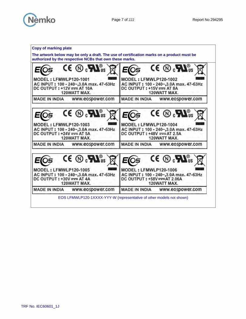
Copy of marking plate
The artwork below may be only a draft. The use of certification marks on a product must be authorized by the respective NCBs that own these marks.
EOS LFMWLP120-1XXXX-YYY-W (representative of other models not shown)

Page 8 of 222 Report No 294295
TRF No. IEC60601_1J
Copy of marking plate
The artwork below may be only a draft. The use of certification marks on a product must be authorized by the respective NCBs that own these marks.
EOS LFMWLP120-1XXXX-YYY-W (representative of other models not shown)

Page 9 of 222 Report No 294295
TRF No. IEC60601_1J
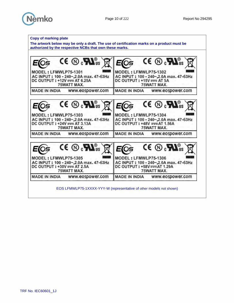
Copy of marking plate
The artwork below may be only a draft. The use of certification marks on a product must be authorized by the respective NCBs that own these marks.
EOS LFMWLP75-1XXXX-YYY-W (representative of other models not shown)
Page 10 of 222 Report No 294295
TRF No. IEC60601_1J
Copy of marking plate
The artwork below may be only a draft. The use of certification marks on a product must be authorized by the respective NCBs that own these marks.
EOS LFMWLP75-1XXXX-YYY-W (representative of other models not shown)

Page 11 of 222 Report No 294295
TRF No. IEC60601_1J
Copy of marking plate
The artwork below may be only a draft. The use of certification marks on a product must be authorized by the respective NCBs that own these marks.
EOS LFMWLP65-1XXXL (representative of other models not shown)
EOS LFMWLP45-1XXXX-YYY-W (representative of other models not shown)

Page 12 of 222 Report No 294295
TRF No. IEC60601_1J
Copy of marking plate
The artwork below may be only a draft. The use of certification marks on a product must be authorized by the respective NCBs that own these marks.
Bel MBC120-1XXXL (representative of other models not shown)
Page 13 of 222 Report No 294295
TRF No. IEC60601_1J
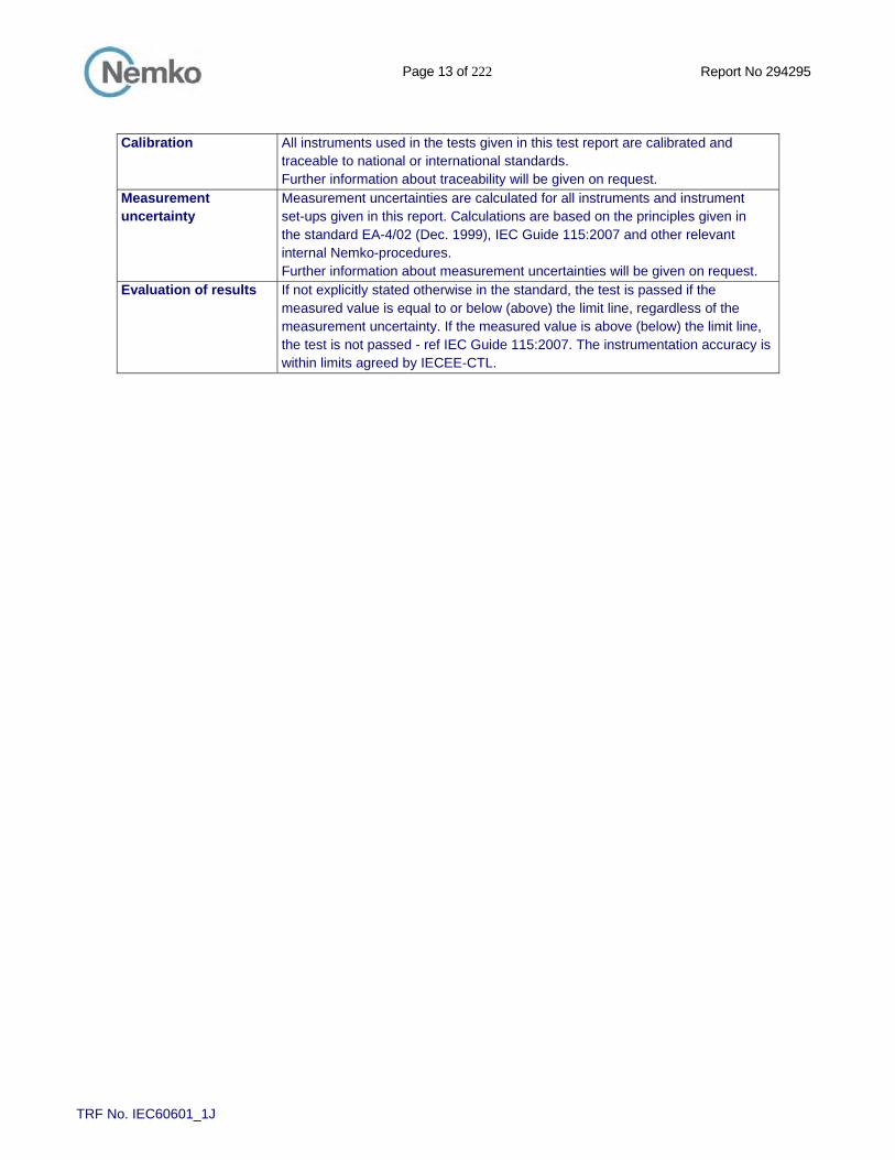
Calibration All instruments used in the tests given in this test report are calibrated and
traceable to national or international standards. Further information about traceability will be given on request.
Measurement uncertainty
Measurement uncertainties are calculated for all instruments and instrument set-ups given in this report. Calculations are based on the principles given in the standard EA-4/02 (Dec. 1999), IEC Guide 115:2007 and other relevant internal Nemko-procedures. Further information about measurement uncertainties will be given on request.
Evaluation of results If not explicitly stated otherwise in the standard, the test is passed if the measured value is equal to or below (above) the limit line, regardless of the measurement uncertainty. If the measured value is above (below) the limit line, the test is not passed - ref IEC Guide 115:2007. The instrumentation accuracy is within limits agreed by IECEE-CTL.
Page 14 of 222 Report No 294295
TRF No. IEC60601_1J
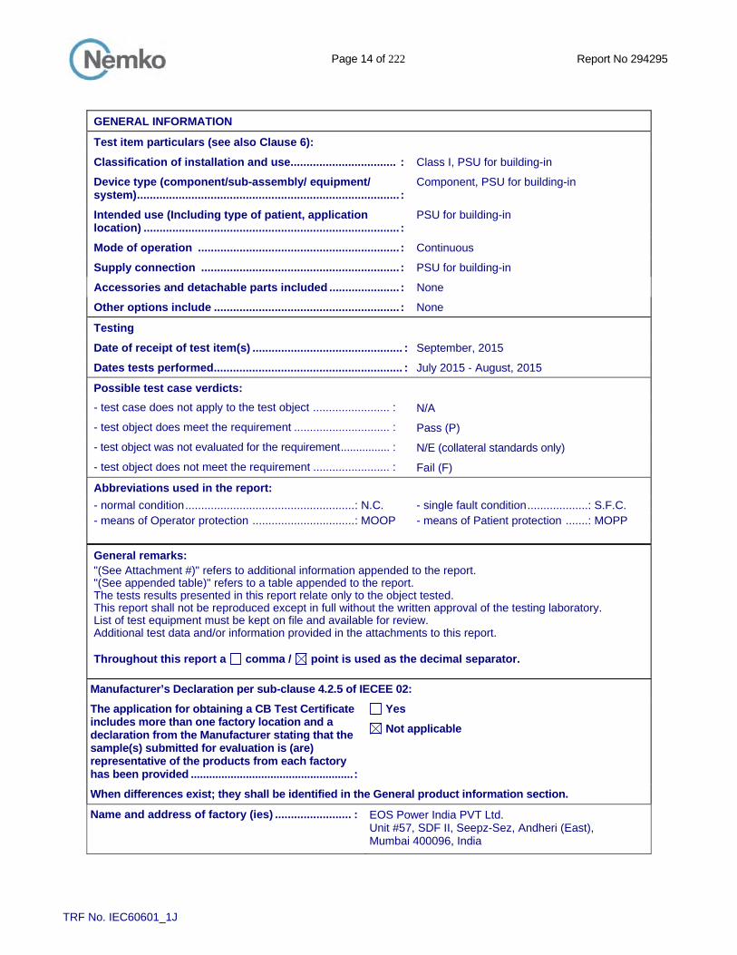
GENERAL INFORMATION
Test item particulars (see also Clause 6):
Classification of installation and use ................................. : Class I, PSU for building-in
Device type (component/sub-assembly/ equipment/ system) .................................................................................. :
Component, PSU for building-in
Intended use (Including type of patient, application location) ................................................................................ :
PSU for building-in
Mode of operation ............................................................... : Continuous
Supply connection .............................................................. : PSU for building-in
Accessories and detachable parts included ...................... : None
Other options include .......................................................... : None
Testing
Date of receipt of test item(s) ............................................... : September, 2015
Dates tests performed ........................................................... : July 2015 - August, 2015
Possible test case verdicts:
- test case does not apply to the test object ........................ : N/A
- test object does meet the requirement .............................. : Pass (P)
- test object was not evaluated for the requirement ................ : N/E (collateral standards only)
- test object does not meet the requirement ........................ : Fail (F)
Abbreviations used in the report:
- normal condition ..................................................... : N.C. - single fault condition ................... : S.F.C. - means of Operator protection ................................ : MOOP - means of Patient protection ....... : MOPP
General remarks: "(See Attachment #)" refers to additional information appended to the report. "(See appended table)" refers to a table appended to the report. The tests results presented in this report relate only to the object tested. This report shall not be reproduced except in full without the written approval of the testing laboratory. List of test equipment must be kept on file and available for review. Additional test data and/or information provided in the attachments to this report. Throughout this report a comma / point is used as the decimal separator.
Manufacturer’s Declaration per sub-clause 4.2.5 of IECEE 02:
The application for obtaining a CB Test Certificate includes more than one factory location and a declaration from the Manufacturer stating that the sample(s) submitted for evaluation is (are) representative of the products from each factory has been provided ..................................................... :
Yes
Not applicable
When differences exist; they shall be identified in the General product information section.
Name and address of factory (ies) ........................ : EOS Power India PVT Ltd. Unit #57, SDF II, Seepz-Sez, Andheri (East), Mumbai 400096, India

Page 15 of 222 Report No 294295
TRF No. IEC60601_1J
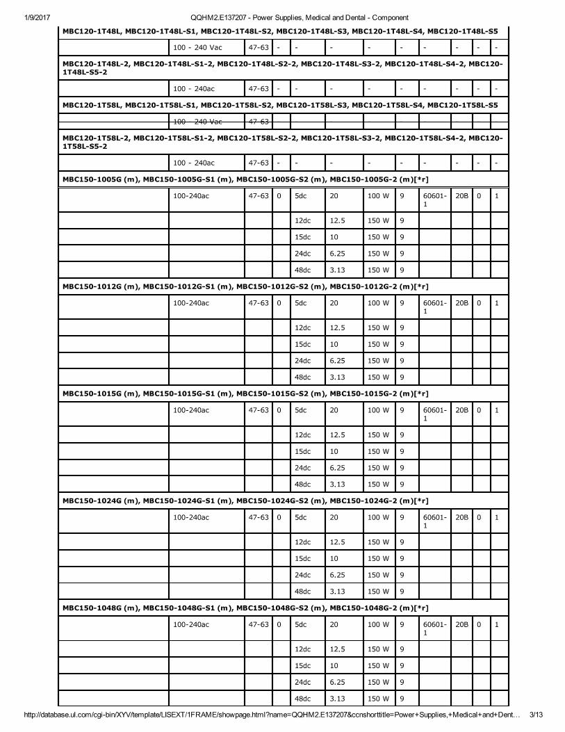
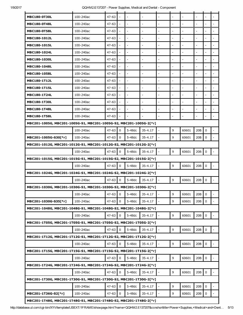
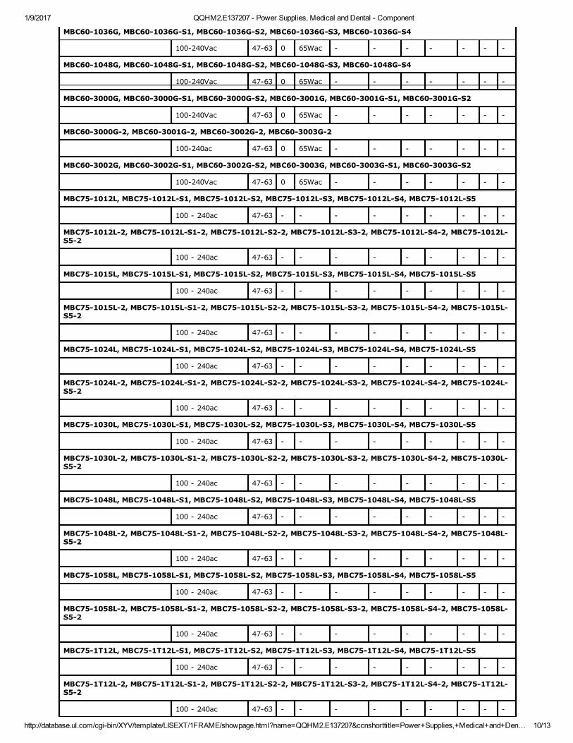
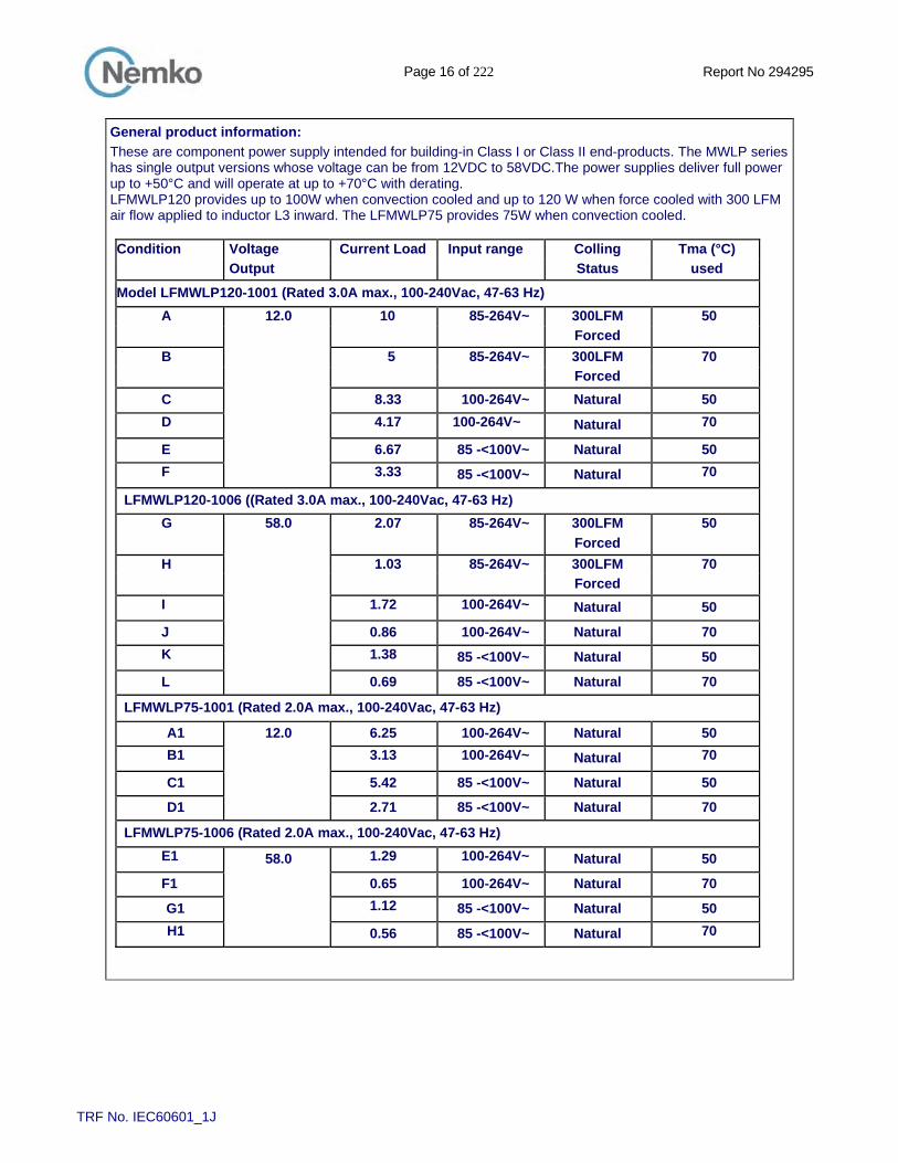
General product information:
LFMWLP120-ZXXX-YYY-W is a series of open frame Class I switch mode power supply intended for building in in medical equipment end-products. The model series has an input range of 100-240V ac, with manufacturer tolerances of -15% to +10% (ranging from 85-264V ac). The model series has single output voltage ranging from 12 to 58V dc. The model series is rated at 120W maximum. The equipment is provided with a PCB-mount molex- type input connector (or equivalent). All models of LFMWLP120-1XXX-YYY-W series are identical, except for the mains transformer (T1) and minor secondary components changes that allow for different output voltage ratings. This test report covers series of models as follows:EOS Corporation: Models are LFMWLP120-1XXX-YYY-W, LFMWLP45-1XXX-YYY-W, LFMWLP65-1XXX-YYY-W, and LFMWLP75-1XXX-YYY-W; and Bel Power Solutions & Protection, a Bel group: Models MBC120-1XXXL-YYY-W,and ABC75-1XXXL-YYY-W. The following are optional configurations for all models: 1) Power supply can be provided as MOPP or MOOP, the only differences are the bridging components used, the PCB layouts are the same for both configurations. For MOPP – 2 Y1 capacitors in series between primary to secondary, opto-couplers are certified according to IEC 60747-5-5 and a single Y capacitor is provided from mains to ground (Y1 or Y2) and optionally from secondary to ground (Y1 for 2 MOPP or Y2 for 1 MOPP). For MOOP - 2 Y1 capacitors in series or a single Y1 capacitor between primary to secondary, opto-couplers are certified according to IEC 60747-5-5 or IEC 60950-1 and a single Y capacitor is provided from mains to ground (Y1 or Y2) and optionally from secondary to ground. 2) The bridging capacitor (depending on MOP, primary to secondary) can be two capacitors or a single capacitor, when single capacitor is provided it is populated in to outer two components pads with midpoint not populated, and is the same values as the total of 2 capacitors. 3) MOV (MV1) is optional. 4) Inductor L5 is optional component provided in protective earth path (on mains section of board) Model differences: For EOS Models LFMWLP120-1XXX-YYY-W, LFMWLP45-1XXX-YYY-W, LFMWLP65-1XXX-YYY-W, and LFWLP75-1XXX-YYY-W. The X (first) = number 0 or 3 denoting type of connector (0- for screw terminal; 3- Header type); XX (second and third) = numbers 01 to 99 denoting output voltage; Y = could be 0-9, AZ, a-z or blank; YYY denotes minor difference and do not effect safety characteristics. Alternative trademark Bel Power Solution is added to this EOS LFMWLP120/75 series with the same construction. The only difference is in the makings for marketing purposes. Testing on the EOS models is representative of the Bel Power Solution models. See table below for examples of equivalent EOS to Bel Power Solution model designations. For Bel Power, Models MBC120-1XXXL-YYY-W or MBC75-1XXXL-YYY-W. The character "X" and "Y" = 0-9, A-Z, a-z or blank. Model correlation to EOS Models are listed in the below table. The model designation variables for Bel Power Solution are defined as follows: X = any alpha or numeric from 0-9 (representing the output voltage) Y = any alpha or numeric character or blank (denotes minor output variation and /or minor SELV circuit variations). W may be blank or 1 with blank denoting models provided with Y1-type capacitors (C33 and C38) bridging mains to secondary (2 MOPP), or 1 denoting models provided with single Y1-type capacitor (C33 or C38 )bridging mains to secondary (2 MOOP); Model LFMWLP120 provides up to 100W when convection cooled and up to 120W when force cooled with 300 LFM air flow. Model LFMWLP75 provides 75W, Model LFMWLP65 provides 65W, and Model LFMWLP45 provides 45W, all models when convection cooled. All models are similar except for output rating, model designation; Transformer (T1) secondary winding and other secondary components. The parameters of these components can be adjusted to obtain corresponding output power and output current. Tma is 50°C or 70°C (with de-rated output). This Report covers an entire series. Refer to appended table for models tested.
Page 16 of 222 Report No 294295
TRF No. IEC60601_1J
General product information:
These are component power supply intended for building-in Class I or Class II end-products. The MWLP series has single output versions whose voltage can be from 12VDC to 58VDC.The power supplies deliver full power up to +50°C and will operate at up to +70°C with derating. LFMWLP120 provides up to 100W when convection cooled and up to 120 W when force cooled with 300 LFM air flow applied to inductor L3 inward. The LFMWLP75 provides 75W when convection cooled. Condition Voltage Current Load Input range Colling Tma (°C)
Output Status used
Model LFMWLP120-1001 (Rated 3.0A max., 100-240Vac, 47-63 Hz)
A 12.0 10 85-264V~ 300LFM 50
Forced
B 5 85-264V~ 300LFM 70
Forced
C 8.33 100-264V~ Natural 50
D 4.17 100-264V~ Natural 70
E 6.67 85 -<100V~ Natural 50
F 3.33 85 -<100V~ Natural 70
LFMWLP120-1006 ((Rated 3.0A max., 100-240Vac, 47-63 Hz)
G 58.0 2.07 85-264V~ 300LFM 50
Forced
H 1.03 85-264V~ 300LFM 70
Forced
I 1.72 100-264V~ Natural 50
J 0.86 100-264V~ Natural 70
K 1.38 85 -<100V~ Natural 50
L 0.69 85 -<100V~ Natural 70
LFMWLP75-1001 (Rated 2.0A max., 100-240Vac, 47-63 Hz)
A1 12.0 6.25 100-264V~ Natural 50
B1 3.13 100-264V~ Natural 70
C1 5.42 85 -<100V~ Natural 50
D1 2.71 85 -<100V~ Natural 70
LFMWLP75-1006 (Rated 2.0A max., 100-240Vac, 47-63 Hz)
E1 58.0 1.29 100-264V~ Natural 50
F1 0.65 100-264V~ Natural 70
G1 1.12 85 -<100V~ Natural 50
H1 0.56 85 -<100V~ Natural 70

Page 17 of 222 Report No 294295
TRF No. IEC60601_1J
General product information:
Letter references in the above table (A to H1) indicates loading condition as noted in the table below. Mentioned below is representative Model Ratings Table for 50°C ambient with 300 LFM air flow from Boost inductor L3.Derated power ratings at 70°C ambient are also specified below: The alphabets in parenthesis represent the overall series loading. Model: LFMWLP120-ZXXX-YYY-W Output Ratings for Input range: 85Vac-264Vac
MODEL
Maximum Individual Continuous Power with 300LFM Forced Air flow & Power Derating at Elevated Temperatures
Voltage 50˚C 70˚C Volts Watts Watts
LFMWLP120-1001 12 120(A) 60(B) LFMWLP120-1002 15 120 60 LFMWLP120-1003 24 120 60 LFMWLP120-1004 48 120 60 LFMWLP120-1005 30 120 60 LFMWLP120-1006 58 120(G) 60(H)
Output Ratings for Convection Cooling
MODEL
Input range: 100Vac-264Vac Maximum Individual Continuous Power with Convection cooling & Power Derating at Elevated Temperatures
Input range: 85Vac - <100Vac Maximum Individual Continuous Power with Convection cooling & Power Derating at Elevated Temperatures
Voltage 50˚C 70˚C 50˚C 70˚C Volts Watts Watts Watts Watts
LFMWLP120-1001 12 100(C) 50(D) 80(E) 40(F) LFMWLP120-1002 15 100 50 80 40 LFMWLP120-1003 24 100 50 80 40 LFMWLP120-1004 48 100 50 80 40 LFMWLP120-1005 30 100 50 80 40 LFMWLP120-1006 58 100(I) 50(J) 80(K) 40 (L)
Model: LFMWLP75-ZXXX-YYY-W Output Ratings for Input range: 100 - 264Vac
MODEL
Maximum Individual Continuous Power with Convection cooling & Power Derating at Elevated Temperatures
Voltage 50˚C 70˚C Volts Watts Watts
LFMWLP75-1001 12 75(A1) 37.5(B1)
LFMWLP75-1002 15 75 37.5
LFMWLP75-1003 24 75 37.5
LFMWLP75-1004 48 75 37.5
LFMWLP75-1005 30 75 37.5
LFMWLP75-1006 58 75(E1) 37.5 (F1)

Page 18 of 222 Report No 294295
TRF No. IEC60601_1J
General product information: Output Ratings for Input range: 85 - <100Vac
MODEL
Maximum Individual Continuous Power with Convection cooling & Power Derating at Elevated Temperatures
Voltage 50˚C 70˚C Volts Watts Watts
LFMWLP75-1001 12 65(C1) 32.5(D1)
LFMWLP75-1002 15 65 32.5
LFMWLP75-1003 24 65 32.5
LFMWLP75-1004 48 65 32.5
LFMWLP75-1005 30 65 32.5
LFMWLP75-1006 58 65 (G1) 32.5 (H1)
The clearance distances have additionally been assessed for suitability up to 5000m elevation. All models have identical schematic and PWB layout

Page 19 of 222 Report No. 294295
IEC 60601-1
Clause Requirement + Test Result - Remark Verdict
TRF No. IEC60601_1J
General product information:
EOS Voltage Current
Custom Bel
Model Number Connector Part Suffix Part Number
LFMWLP120-1001 Screw Terminal 12V 10A MBC120-1T12L
LFMWLP120-1301 Header MBC120-1012L
LFMWLP120-1002 Screw Terminal 15V 8A MBC120-1T15L
LFMWLP120-1302 Header MBC120-1015L
LFMWLP120-1003 Screw Terminal 24V 5A MBC120-1T24L
LFMWLP120-1303 Header MBC120-1024L
LFMWLP120-1004 Screw Terminal 48V 2.5A MBC120-1T48L
LFMWLP120-1304 Header MBC120-1048L
LFMWLP120-1005 Screw Terminal 30V 4A MBC120-1T30L
LFMWLP120-1305 Header MBC120-1030L
LFMWLP120-1006 Screw Terminal 58V 2.06A MBC120-1T58L
LFMWLP120-1306 Header MBC120-1058L
LFMWLP75-1001 Screw Terminal 12V 6.25A MBC75-1T12L
LFMWLP75-1301 Header MBC75-1012L
LFMWLP75-1002 Screw Terminal 15V 5.00A MBC75-1T15L
LFMWLP75-1302 Header MBC75-1015L
LFMWLP75-1003 Screw Terminal 24V 3.13A MBC75-1T24L
LFMWLP75-1303 Header MBC75-1024L
LFMWLP75-1004 Screw Terminal 48V 1.56A MBC75-1T48L
LFMWLP75-1304 Header MBC75-1048L
LFMWLP75-1005 Screw Terminal 30V 2.50A MBC75-1T30L
Page 20 of 222 Report No. 294295
IEC 60601-1
Clause Requirement + Test Result - Remark Verdict
TRF No. IEC60601_1J
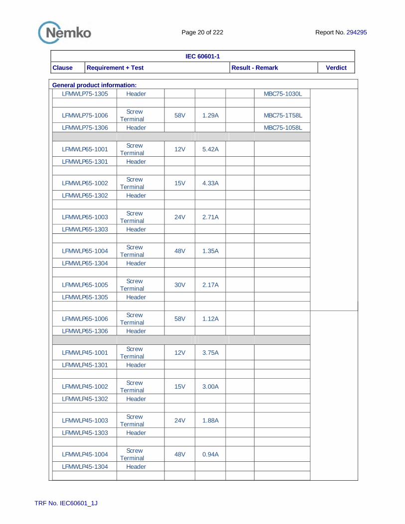
General product information: LFMWLP75-1305 Header MBC75-1030L
LFMWLP75-1006 Screw Terminal 58V 1.29A MBC75-1T58L
LFMWLP75-1306 Header MBC75-1058L
LFMWLP65-1001 Screw Terminal 12V 5.42A
LFMWLP65-1301 Header
LFMWLP65-1002 Screw Terminal 15V 4.33A
LFMWLP65-1302 Header
LFMWLP65-1003 Screw Terminal 24V 2.71A
LFMWLP65-1303 Header
LFMWLP65-1004 Screw Terminal 48V 1.35A
LFMWLP65-1304 Header
LFMWLP65-1005 Screw Terminal 30V 2.17A
LFMWLP65-1305 Header
LFMWLP65-1006 Screw Terminal 58V 1.12A
LFMWLP65-1306 Header
LFMWLP45-1001 Screw Terminal 12V 3.75A
LFMWLP45-1301 Header
LFMWLP45-1002 Screw Terminal 15V 3.00A
LFMWLP45-1302 Header
LFMWLP45-1003 Screw Terminal 24V 1.88A
LFMWLP45-1303 Header
LFMWLP45-1004 Screw Terminal 48V 0.94A
LFMWLP45-1304 Header

Page 21 of 222 Report No. 294295
IEC 60601-1
Clause Requirement + Test Result - Remark Verdict
TRF No. IEC60601_1J
General product information:
LFMWLP45-1005 Screw Terminal 30V 1.50A
LFMWLP45-1305 Header
LFMWLP45-1006 Screw Terminal 58V 0.78A
LFMWLP45-1306 Header
λºò Ý»®¬·ºò Ò±ò
ÒÑèçðêí
Ù¿«¬¿¼¿´´7»² íðÒÑóðíéí Ñ´±ô Ò±®©¿§
Ü¿¬»æ îèóïðóîðïë Í·¹²¿¬«®»æ Ö«¿² Æò Õ´»°°»²»Ý»®¬·º·½¿¬·±² Ü»°¿®¬³»²¬
׫»¼ îððéóðì ïñï
×ÛÝ ÍÇÍÌÛÓ ÚÑÎ ÓËÌËßÔ ÎÛÝÑÙÒ×Ì×ÑÒ ÑÚ ÌÛÍÌ ÝÛÎÌ×Ú×ÝßÌÛÍ ÚÑÎ ÛÔÛÝÌÎ×ÝßÔÛÏË×ÐÓÛÒÌ ø×ÛÝÛÛ÷ ÝÞ ÍÝØÛÓÛ
ÍÇÍÌÛÓÛ ÝÛ× ÜßÝÝÛÐÌßÌ×ÑÒ ÓËÌËÛÔÔÛ ÜÛ ÝÛÎÌ×Ú×ÝßÌÍ ÜÛÍÍß×Í ÜÛÍÛÏË×ÐÛÓÛÒÌÍ ÛÔÛÝÌÎ×ÏËÛÍ ø×ÛÝÛÛ÷ ÓÛÌØÑÜÛ ÑÝ
ÝÞ ÌÛÍÌ ÝÛÎÌ×Ú×ÝßÌÛ ÝÛÎÌ×Ú×ÝßÌ ÜùÛÍÍß× ÑÝ
Ю±¼«½¬Ð®±¼«·¬ Ó»¼·½¿´ °±©»® «°°´§ º±® ø ¾«·´¼·²¹ó·² ÷
Ò¿³» ¿²¼ ¿¼¼®» ±º ¬¸» ¿°°´·½¿²¬Ò±³ »¬ ¿¼®»» ¼« ¼»³¿²¼»«®
Ò¿³» ¿²¼ ¿¼¼®» ±º ¬¸» ³¿²«º¿½¬«®»®Ò±³ »¬ ¿¼®»» ¼« º¿¾®·½¿²¬
Ò¿³» ¿²¼ ¿¼¼®» ±º ¬¸» º¿½¬±®§Ò±³ »¬ ¿¼®»» ¼» ´ù«·²»
Ò±¬»æ ɸ»² ³±®» ¬¸¿² ±²» º¿½¬±®§ô °´»¿» ®»°±®¬ ±² °¿¹» îÒ±¬»æ Ô±®¯«» ·´ § °´« ¼ù«²» «·²»ô ª»«·´´»¦ «¬·´·»® ´¿ ¼»«¨·8³» °¿¹»
ß¼¼·¬·±²¿´ ·²º±®³¿¬·±² ±² °¿¹» î
ο¬·²¹ ¿²¼ °®·²½·°¿´ ½¸¿®¿½¬»®·¬·½Ê¿´»«® ²±³·²¿´» »¬ ½¿®¿½¬7®·¬·¯«» °®·²½·°¿´»
îòð ß Ó¿¨ô ïððóîìð Ê¢ ìéóêí ئô Ý´ò ××
Ì®¿¼»³¿®µ ø·º ¿²§÷Ó¿®¯«» ¼» º¿¾®·¯«» ø· »´´» »¨·¬»÷
̧°» ±º Ó¿²«º¿½¬«®»®� Ì»¬·²¹ Ô¿¾±®¿¬±®·» «»¼Ì§°» ¼» °®±¹®¿³³» ¼« ´¿¾±®¿¬±·®» ¼�»¿· ½±²¬®«½¬»«®
Ó±¼»´ ñ ̧°» λºòλºò Ü» ¬§°»
ÓÞÝéëóïÈÈÈÔóÇÇÇóî
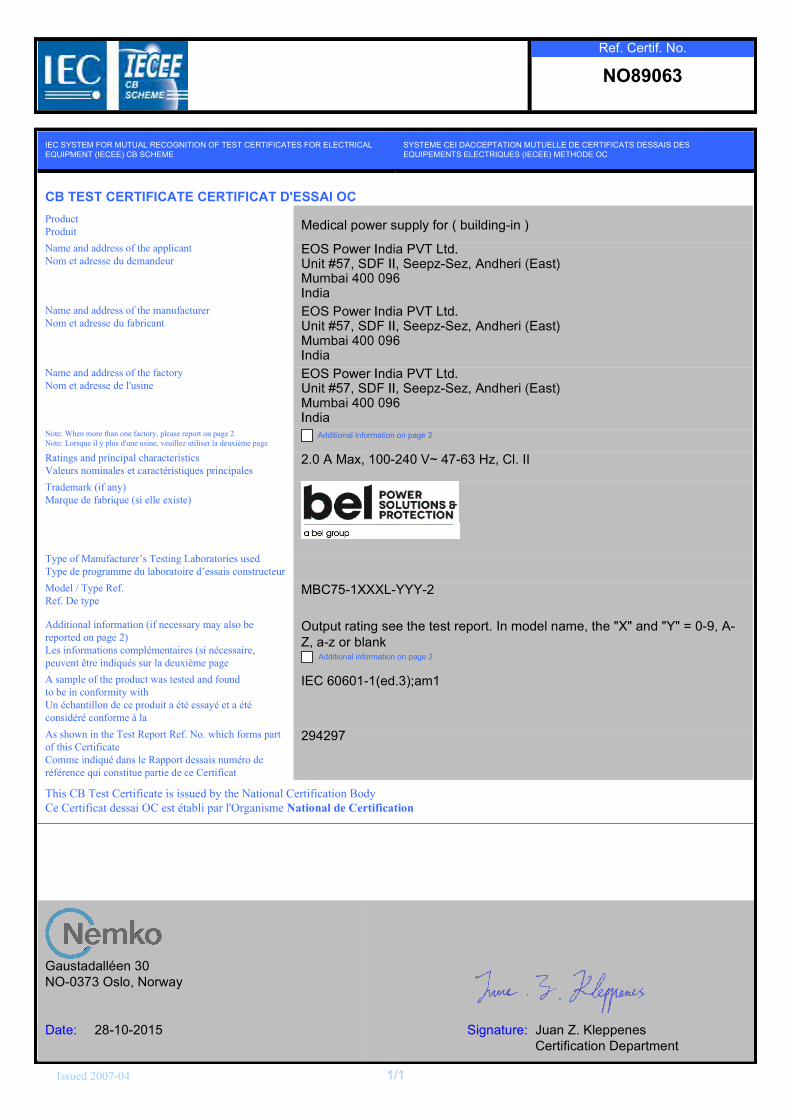
ß¼¼·¬·±²¿´ ·²º±®³¿¬·±² ø·º ²»½»¿®§ ³¿§ ¿´± ¾»®»°±®¬»¼ ±² °¿¹» î÷Ô» ·²º±®³¿¬·±² ½±³°´7³»²¬¿·®» ø· ²7½»¿·®»ô°»«ª»²¬ 6¬®» ·²¼·¯«7 «® ´¿ ¼»«¨·8³» °¿¹»
Ñ«¬°«¬ ®¿¬·²¹ »» ¬¸» ¬»¬ ®»°±®¬ò ײ ³±¼»´ ²¿³»ô ¬¸» þÈþ ¿²¼ þÇþ ã ðóçô ßóÆô ¿ó¦ ±® ¾´¿²µ
ß¼¼·¬·±²¿´ ·²º±®³¿¬·±² ±² °¿¹» î
ß ¿³°´» ±º ¬¸» °®±¼«½¬ ©¿ ¬»¬»¼ ¿²¼ º±«²¼¬± ¾» ·² ½±²º±®³·¬§ ©·¬¸Ë² 7½¸¿²¬·´´±² ¼» ½» °®±¼«·¬ ¿ 7¬7 »¿§7 »¬ ¿ 7¬7½±²·¼7®7 ½±²º±®³» @ ´¿
×ÛÝ êðêðïóïø»¼òí÷忳ï
ß ¸±©² ·² ¬¸» Ì»¬ λ°±®¬ λºò Ò±ò ©¸·½¸ º±®³ °¿®¬±º ¬¸· Ý»®¬·º·½¿¬»Ý±³³» ·²¼·¯«7 ¼¿² ´» ο°°±®¬ ¼»¿· ²«³7®± ¼»®7º7®»²½» ¯«· ½±²¬·¬«» °¿®¬·» ¼» ½» Ý»®¬·º·½¿¬
îçìîçé
̸· ÝÞ Ì»¬ Ý»®¬·º·½¿¬» · ·«»¼ ¾§ ¬¸» Ò¿¬·±²¿´ Ý»®¬·º·½¿¬·±² Þ±¼§Ý» Ý»®¬·º·½¿¬ ¼»¿· ÑÝ »¬ 7¬¿¾´· °¿® ´ùÑ®¹¿²·³» Ò¿¬·±²¿´ ¼» Ý»®¬·º·½¿¬·±²

λºò Ý»®¬·ºò Ò±ò
ÒÑèçðêì
Ù¿«¬¿¼¿´´7»² íðÒÑóðíéí Ñ´±ô Ò±®©¿§
Ü¿¬»æ îèóïðóîðïë Í·¹²¿¬«®»æ Ö«¿² Æò Õ´»°°»²»Ý»®¬·º·½¿¬·±² Ü»°¿®¬³»²¬
׫»¼ îððéóðì ïñï
×ÛÝ ÍÇÍÌÛÓ ÚÑÎ ÓËÌËßÔ ÎÛÝÑÙÒ×Ì×ÑÒ ÑÚ ÌÛÍÌ ÝÛÎÌ×Ú×ÝßÌÛÍ ÚÑÎ ÛÔÛÝÌÎ×ÝßÔÛÏË×ÐÓÛÒÌ ø×ÛÝÛÛ÷ ÝÞ ÍÝØÛÓÛ
ÍÇÍÌÛÓÛ ÝÛ× ÜßÝÝÛÐÌßÌ×ÑÒ ÓËÌËÛÔÔÛ ÜÛ ÝÛÎÌ×Ú×ÝßÌÍ ÜÛÍÍß×Í ÜÛÍÛÏË×ÐÛÓÛÒÌÍ ÛÔÛÝÌÎ×ÏËÛÍ ø×ÛÝÛÛ÷ ÓÛÌØÑÜÛ ÑÝ
ÝÞ ÌÛÍÌ ÝÛÎÌ×Ú×ÝßÌÛ ÝÛÎÌ×Ú×ÝßÌ ÜùÛÍÍß× ÑÝ
Ю±¼«½¬Ð®±¼«·¬ Ó»¼·½¿´ °±©»® «°°´§ º±® ø ¾«·´¼·²¹ó·² ÷
Ò¿³» ¿²¼ ¿¼¼®» ±º ¬¸» ¿°°´·½¿²¬Ò±³ »¬ ¿¼®»» ¼« ¼»³¿²¼»«®
Ò¿³» ¿²¼ ¿¼¼®» ±º ¬¸» ³¿²«º¿½¬«®»®Ò±³ »¬ ¿¼®»» ¼« º¿¾®·½¿²¬
Ò¿³» ¿²¼ ¿¼¼®» ±º ¬¸» º¿½¬±®§Ò±³ »¬ ¿¼®»» ¼» ´ù«·²»
Ò±¬»æ ɸ»² ³±®» ¬¸¿² ±²» º¿½¬±®§ô °´»¿» ®»°±®¬ ±² °¿¹» îÒ±¬»æ Ô±®¯«» ·´ § °´« ¼ù«²» «·²»ô ª»«·´´»¦ «¬·´·»® ´¿ ¼»«¨·8³» °¿¹»
ß¼¼·¬·±²¿´ ·²º±®³¿¬·±² ±² °¿¹» î
ο¬·²¹ ¿²¼ °®·²½·°¿´ ½¸¿®¿½¬»®·¬·½Ê¿´»«® ²±³·²¿´» »¬ ½¿®¿½¬7®·¬·¯«» °®·²½·°¿´»
ßÝ ×²°«¬æ íòð ß Ó¿¨ ïððó îìð Ê¢ ìéó êí ئô Ý×ò ××
Ì®¿¼»³¿®µ ø·º ¿²§÷Ó¿®¯«» ¼» º¿¾®·¯«» ø· »´´» »¨·¬»÷
̧°» ±º Ó¿²«º¿½¬«®»®� Ì»¬·²¹ Ô¿¾±®¿¬±®·» «»¼Ì§°» ¼» °®±¹®¿³³» ¼« ´¿¾±®¿¬±·®» ¼�»¿· ½±²¬®«½¬»«®
Ó±¼»´ ñ ̧°» λºòλºò Ü» ¬§°»
ÓÞÝïîðóïÈÈÈÔóÇÇÇóî
ß¼¼·¬·±²¿´ ·²º±®³¿¬·±² ø·º ²»½»¿®§ ³¿§ ¿´± ¾»®»°±®¬»¼ ±² °¿¹» î÷Ô» ·²º±®³¿¬·±² ½±³°´7³»²¬¿·®» ø· ²7½»¿·®»ô°»«ª»²¬ 6¬®» ·²¼·¯«7 «® ´¿ ¼»«¨·8³» °¿¹»
Ñ«¬°«¬ ®¿¬·²¹ »» ¬¸» ¬»¬ ®»°±®¬ò ײ ³±¼»´ ²¿³»ô ¬¸» þÈþ ¿²¼ þÇþ ã ðóçô ßóÆô ¿ó¦ ±® ¾´¿²µ
ß¼¼·¬·±²¿´ ·²º±®³¿¬·±² ±² °¿¹» î
ß ¿³°´» ±º ¬¸» °®±¼«½¬ ©¿ ¬»¬»¼ ¿²¼ º±«²¼¬± ¾» ·² ½±²º±®³·¬§ ©·¬¸Ë² 7½¸¿²¬·´´±² ¼» ½» °®±¼«·¬ ¿ 7¬7 »¿§7 »¬ ¿ 7¬7½±²·¼7®7 ½±²º±®³» @ ´¿
×ÛÝ êðêðïóïø»¼òí÷忳ï
ß ¸±©² ·² ¬¸» Ì»¬ λ°±®¬ λºò Ò±ò ©¸·½¸ º±®³ °¿®¬±º ¬¸· Ý»®¬·º·½¿¬»Ý±³³» ·²¼·¯«7 ¼¿² ´» ο°°±®¬ ¼»¿· ²«³7®± ¼»®7º7®»²½» ¯«· ½±²¬·¬«» °¿®¬·» ¼» ½» Ý»®¬·º·½¿¬
îçìîçé
̸· ÝÞ Ì»¬ Ý»®¬·º·½¿¬» · ·«»¼ ¾§ ¬¸» Ò¿¬·±²¿´ Ý»®¬·º·½¿¬·±² Þ±¼§Ý» Ý»®¬·º·½¿¬ ¼»¿· ÑÝ »¬ 7¬¿¾´· °¿® ´ùÑ®¹¿²·³» Ò¿¬·±²¿´ ¼» Ý»®¬·º·½¿¬·±²

Test Report issued under the responsibility of
www.nemko.com
This Test Report, when bearing the Nemko name and logo is only valid when issued by a Nemko laboratory, or by a laboratory having special agreement with Nemko.
IEC 60601-1 Medical electrical equipment
Part 1: General requirements for basic safety and essential performance Report Reference No. .................... : 294297
Date of issue .................................. : 27 October 2015
Total number of pages .................. : 222
CB Testing Laboratory .................. : Nemko USA Inc. Phone: +1 760 444 3500
Address .......................................... : 2210 Faraday Avenue, Suite 150, Carlsbad, CA 92008, USA
Applicant’s name ........................... : EOS Power India PVT Ltd.
Address .......................................... : Unit #57, SDF II, Seepz-Sez, Andheri (E), Mumbai, 400096, India
Test specification:
Standard ......................................... : IEC 60601-1: 2005 + CORR. 1:2006 + CORR. 2:2007 + AM1:2012 (or IEC 60601-1: 2012 reprint)
Test procedure ............................... : CB Scheme
Non-standard test method………..: N/A
Test Report Form No. .................... : IEC60601_1J
Test Report Form Originator ......... : UL(US)
Master TRF ..................................... : 2014-07
Copyright © 2014 Worldwide System for Conformity Testing and Certification of Electrotechnical Equipment and Components (IECEE), Geneva, Switzerland. All rights reserved. This publication may be reproduced in whole or in part for non-commercial purposes as long as the IECEE is acknowledged as copyright owner and source of the material. IECEE takes no responsibility for and will not assume liability for damages resulting from the reader's interpretation of the reproduced material due to its placement and context.
If this Test Report Form is used by non-IECEE members, the IECEE/IEC logo and the reference to the CB Scheme procedure shall be removed.
This report is not valid as a CB Test Report unless signed by an approved CB Testing Laboratory and appended to a CB Test Certificate issued by an NCB in accordance with IECEE 02.
General disclaimer: The test results presented in this report relate only to the object tested. This report shall not be reproduced, except in full, without the written approval of the Issuing CB testing laboratory. The authenticity of this Test Report and its contents can be verified by contacting the NCB, responsible for this Test Report.
Page 2 of 221 Report No 294297
TRF No. IEC60601_1J
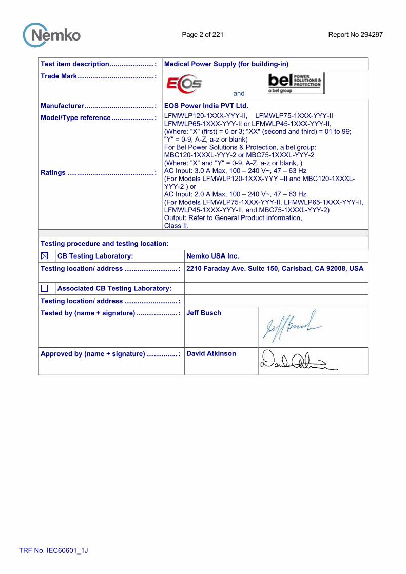
Test item description ....................... : Medical Power Supply (for building-in)
Trade Mark........................................ :
and
Manufacturer .................................... : EOS Power India PVT Ltd.
Model/Type reference ...................... : LFMWLP120-1XXX-YYY-II, LFMWLP75-1XXX-YYY-II LFMWLP65-1XXX-YYY-II or LFMWLP45-1XXX-YYY-II, (Where: "X" (first) = 0 or 3; "XX" (second and third) = 01 to 99; "Y" = 0-9, A-Z, a-z or blank) For Bel Power Solutions & Protection, a bel group: MBC120-1XXXL-YYY-2 or MBC75-1XXXL-YYY-2 (Where: "X" and "Y" = 0-9, A-Z, a-z or blank, )
Ratings ............................................. : AC Input: 3.0 A Max, 100 – 240 V~, 47 – 63 Hz (For Models LFMWLP120-1XXX-YYY –II and MBC120-1XXXL-YYY-2 ) or AC Input: 2.0 A Max, 100 – 240 V~, 47 – 63 Hz (For Models LFMWLP75-1XXX-YYY-II, LFMWLP65-1XXX-YYY-II, LFMWLP45-1XXX-YYY-II, and MBC75-1XXXL-YYY-2) Output: Refer to General Product Information, Class II.
Testing procedure and testing location:
CB Testing Laboratory: Nemko USA Inc.
Testing location/ address ............................ : 2210 Faraday Ave. Suite 150, Carlsbad, CA 92008, USA
Associated CB Testing Laboratory:
Testing location/ address ............................ :
Tested by (name + signature) ..................... : Jeff Busch
Approved by (name + signature) ................ : David Atkinson

Page 3 of 221 Report No 294297
TRF No. IEC60601_1J
List of Attachments (including a total number of pages in each attachment):
Document Appended 1: Photographs (Page number #179)
Document Appended 2: PCB trace layouts (Page number #181)
Document Appended 3: Circuit diagrams (Page number #184)
Document Appended 4: Transformer and Inductor drawings (Page number #185)
Attachment 1: National differences (22 pages)
Attachment 2: Installation instructions (2 page)
Summary of testing:
Clause Requirement + Test Comment All Information about the standards,
documents considered European Countries, EN 60601-1 (2006) +A11 (2011) + AM1:2013 +AC:2014 +A12:2014. Refer also to National Differences attachment.1
All General The equipment is an open-frame, Class II switch mode power supply with universal AC input and multiple DC voltage outputs for building-in. This report covers multiple models and all comments / tests apply to all models unless otherwise indicated. Testing was conducted on various models as indicated.
All General The LFMWLP120/75/65/45 series of power supplied are provided in both a Class I configuration (covered under separate test report) and a Class II configuration (covered in this test report). The only difference is that Inductance L5(optional), capacitance C2, C3, C5,C32, and protective earthing/bonding terminal M1 and M2; are not populated and the removal of the protective earth symbol next to the mounting pad. All traces and silk screening (component designations) are provided on the PCB for the depopulated components. To maintain Class II safety isolation, if needed in the end insulation, those mounting holes that are near hazardous parts (mains) need to be isolated from earth, secondary circuits and /or conductive accessible parts, by the use of standoffs of non-conductive material or other means. The safety isolation needs to be verified in the end installation.
All General Unless otherwise noted, testing in this report covers worst-case testing on 12V (LFMWLP120-1001-II 12V (LFMWLP75-1001-II) and 58V ( LFMWLP120-1006-II) (LFMWLP75-1006-II ) output units, which is considered representative of the other models.
All Risk Management The manufacturer performed the Risk Management process according to ISO 14971, 2nd edition.
All Rated ambient temperature range The power supply has been evaluated for 50°C when fully rated and de-rated at 70°C ambient as well as 85V (-15% tolerance) and 100V rating, temperatures as noted within this report. The Tmra must be checked when the equipment is built in an end product, or forms a part of a complete system.

Page 4 of 221 Report No 294297
TRF No. IEC60601_1J
Summary of testing:
Clause Requirement + Test Comment 4.3 Essential performance functions
identified according to manufacturer’s policy for risk acceptability in risk management file
Essential performance shall be determined when installed in the end-use equipment as part of the risk management process for the end product.
4.5 Equvalent safety The optocouplers (U2) have been separately tested and approved to the relevant component standard, (EN 60747-5-5) by VDE. The component certification is considered to provide equivalent safety for two means of patient protection (2 MOPPs), refer to Insulation Diagram for defined patient protection. The PCB, transformer and bridging Ycapacitors comply with IEC 60601-1 (ed.3) requirements for patient protection
4.6 Risk management process identifies parts that can come into contact with patient but not defined as applied parts subjected to the requirements for applied parts, except for 7.2.10
Output of the PSU was not evaluated nor was it considered for direct contact to the patient; additional evaluation will be required in the end installation
4.7 ME equipment remained single fault safe, or the risk remained acceptable as determined by 4.2
Risk considered as part of this evaluation, refer to RM Results appended table 4.7.
4.8 Components of ME equipment The equipment is evaluated as MOPP and MOOP the only difference is the bridging components used the PCB layous and distances on the PCB are the same. For MOPP - The optocouplers (U2) have been separately tested and approved to the relevant component standard (EN 60747-5-5) by VDE. The component certification is considered to provide equivalent safety for two means of patient protection (2 MOPPs), refer to Insulation Diagram for defined operator and patient protection. The primary to secondary capacitors are 2 Y1 capcitors in series. For MOOP - The optocouplers (U2) that are not approved to 60747-5-5 are only considered as providing two means of operator protection (2 MOOP’s). The primary to secondary capacitor can be a single Y1 capacitor. Acceptance of the optocoupler is at the discretion of the accepting NCB or agency. The PCB and transformer comply with IEC 60601-1 (ed.3) requirements for patient protection.
5.9 Determination of applied parts and accessible parts
Output of the PSU was not evaluated nor was it considered for direct contact to the patient, additional evaluation will be required in the end installation.
7 Identification, markings and documents
Instructions and marking related to safety shall be in a language which is acceptable in the country in which the equipment is to be sold. English version evaluated.
7.9 Accompanying documents The equipment is a PSU for building-in. The end product evaluation shall ensure that the requirements related to accompanying documents complying with this standard are met in which is provided in the language required for the market where the equipment is sold.
Page 5 of 221 Report No 294297
TRF No. IEC60601_1J
Summary of testing:
Clause Requirement + Test Comment
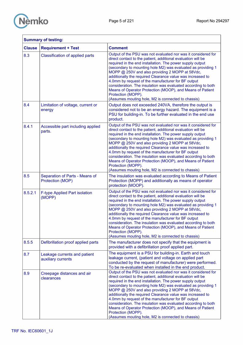
8.3 Classification of applied parts Output of the PSU was not evaluated nor was it considered for direct contact to the patient, additional evaluation will be required in the end installation. The power supply output (secondary to mounting hole M2) was evaluated as providing 1 MOPP @ 250V and also providing 2 MOPP at 58Vdc, additionally the required Clearance value was increased to 4.0mm by request of the manufacturer for BF output consideration. The insulation was evaluated according to both Means of Operator Protection (MOOP), and Means of Patient Protection (MOPP). (Assumes mouting hole, M2 is connected to chassis)
8.4 Limitation of voltage, current or energy
Output does not exceeded 240VA, therefore the output is considered not to be an energy hazard. The equipment is a PSU for building-in. To be further evaluated in the end use product.
8.4.1 Accessible part including applied parts.
Output of the PSU was not evaluated nor was it considered for direct contact to the patient, additional evaluation will be required in the end installation. The power supply output (secondary to mounting hole M2) was evaluated as providing 1 MOPP @ 250V and also providing 2 MOPP at 58Vdc, additionally the required Clearance value was increased to 4.0mm by request of the manufacturer for BF output consideration. The insulation was evaluated according to both Means of Operator Protection (MOOP), and Means of Patient Protection (MOPP). (Assumes mouting hole, M2 is connected to chassis)
8.5 Separation of Parts - Means of Protection (MOP)
The insulation was evaluated according to Means of Patient Protection (MOPP) and additionally as means of operator protection (MOOP).
8.5.2.1 F-type Applied Part isolation (MOPP)
Output of the PSU was not evaluated nor was it considered for direct contact to the patient, additional evaluation will be required in the end installation. The power supply output (secondary to mounting hole M2) was evaluated as providing 1 MOPP @ 250V and also providing 2 MOPP at 58Vdc, additionally the required Clearance value was increased to 4.0mm by request of the manufacturer for BF output consideration. The insulation was evaluated according to both Means of Operator Protection (MOOP), and Means of Patient Protection (MOPP). (Assumes mouting hole, M2 is connected to chassis)
8.5.5 Defibrillation proof applied parts The manufacturer does not specify that the equipment is provided with a defibrillation proof applied part.
8.7 Leakage currents and patient auxiliary currents
The equipment is a PSU for building-in. Earth and touch leakage current, (patient and voltage on applied part conducted by the request of manufacturer) were performed. To be re-evaluated when installed in the end product.
8.9 Creepage distances and air clearances
Output of the PSU was not evaluated nor was it considered for direct contact to the patient, additional evaluation will be required in the end installation. The power supply output (secondary to mounting hole M2) was evaluated as providing 1 MOPP @ 250V and also providing 2 MOPP at 58Vdc, additionally the required Clearance value was increased to 4.0mm by request of the manufacturer for BF output consideration. The insulation was evaluated according to both Means of Operator Protection (MOOP), and Means of Patient Protection (MOPP). (Assumes mouting hole, M2 is connected to chassis)

Page 6 of 221 Report No 294297
TRF No. IEC60601_1J
Summary of testing:
Clause Requirement + Test Comment
8.9.1.2 Creepage distances and air clearances complying with IEC 60950-1.
MOPP or MOOP Optocouplers have been separately identified in appended table 8.10. Optocouplers accepted for MOOP based on IEC 60950-1 certification.
8.11.5 Mains fuses Low-breaking capacity fusing is considered adequate based on a diode bridge (D1) short circuit current that measured less than 10 times the fusing rating with the use of (RT1) and (L1) components. Additionally the primary common-mode inductor (L1) component separately passed a 1 MOPP dielectric strength test, refer to appended table 8.8.3. Construction acceptance is at the discretion of the receiving agency.
11.1 Protection against excessive temperatures and other hazards
This report covers a series of power supply models. Testing was performed on various models as indicated in this report. This testing was considered representative for all models. Unless otherwise stated, all tests were performed on worst-case model.
11.1.1 Maximum temperature during normal use
The Tma for the maximum output rating is 50°C for most models. Power supplies can operate in up to a 70°C ambient with a derated output load, refer to General product information and appended table 11.1.1.
11.3b Constructional requirements for fire enclosures of ME equipment
The equipment is a PSU for building-in which provide >15W output. The PSU must be provided with a suitable fire enclosure. The fire enclosure shall be evaluated in the end product.
11.7 ME equipment, ME system, and accessories coming into direct or indirect contact with biological tissues, cells, or body fluids assessed and documented according to ISO 10993
The equipment is a PSU for building-in. The end-use equipment must be evaluated to determine compliance with the requirements of ISO 10993-1.
17 Electromagnetic compatibility of ME equipment and ME systems
The equipment is a component level power supply for building-in, the requirements to this clause have to be evaluated in the end product. Additionally, the equipment has been evaluated for the requirements of IEC 60601-2 as a component power supply. Documentation is maintained by the manufacturer.
Tests performed (name of test and test clause):
4.11: Power input 5.7: Humidity and preconditioning treatment 7.1.3: Durability of marking 8.4.2: Working voltage / Power measurement 8.4.3: Plug-measurement of voltage 8.6.4 Protective earthing 8.7: Leakage current 8.8.3: Dielectric strength 8.8.4.1: Mechanical strength and resistance to heat 11.1: Excessive temperatures 11.8: Interruption of power supply 13.2: Single fault conditions 15.5: Transformers
Testing location: See Page 2

Page 7 of 221 Report No 294297
TRF No. IEC60601_1J
Summary of testing:
Clause Requirement + Test Comment
Summary of compliance with National Differences
List of countries addressed:
All CENELEC members according to EN 60601-1 (2006) +A11 (2011) + AM1:2013 +AC:2014 +A12:2014.
The list of countries recognizing the CB Scheme is actively updated on the IECEE website. (http://www.iecee.org/)
All CB members as listed in the IECEE Online Bulletin Canada, Switzerland, Japan, Korea, United States.
The product fulfils the requirements of IEC/EN 60601-1 Edition 3.0 + AM1
Page 8 of 221 Report No 294297
TRF No. IEC60601_1J
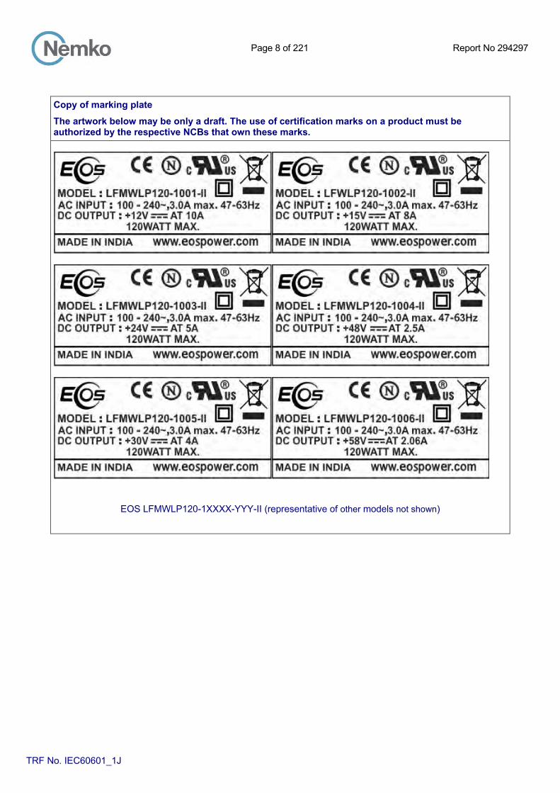
Copy of marking plate
The artwork below may be only a draft. The use of certification marks on a product must be authorized by the respective NCBs that own these marks.
EOS LFMWLP120-1XXXX-YYY-II (representative of other models not shown)
Page 9 of 221 Report No 294297
TRF No. IEC60601_1J
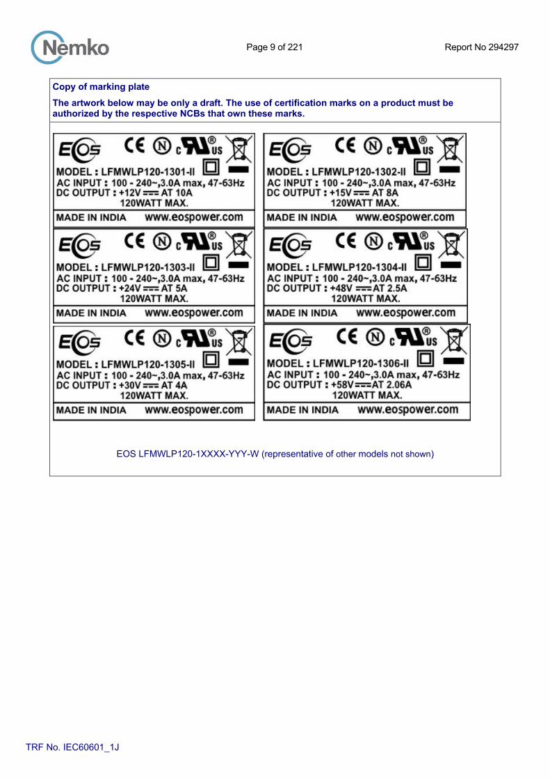
Copy of marking plate
The artwork below may be only a draft. The use of certification marks on a product must be authorized by the respective NCBs that own these marks.
EOS LFMWLP120-1XXXX-YYY-W (representative of other models not shown)

Page 10 of 221 Report No 294297
TRF No. IEC60601_1J
Copy of marking plate The artwork below may be only a draft. The use of certification marks on a product must be authorized by the respective NCBs that own these marks.
EOS LFMWLP75-1XXXX-YYY-II (representative of other models not shown)

Page 11 of 221 Report No 294297
TRF No. IEC60601_1J
Copy of marking plate The artwork below may be only a draft. The use of certification marks on a product must be authorized by the respective NCBs that own these marks.
EOS LFMWLP75-1XXXX-YYY-W (representative of other models not shown)

Page 12 of 221 Report No 294297
TRF No. IEC60601_1J
Copy of marking plate The artwork below may be only a draft. The use of certification marks on a product must be authorized by the respective NCBs that own these marks.
EOS LFMWLP65-1XXXL-II (representative of other models not shown)

Page 13 of 221 Report No 294297
TRF No. IEC60601_1J
Copy of marking plate The artwork below may be only a draft. The use of certification marks on a product must be authorized by the respective NCBs that own these marks.
Bel MBC120-1XXXL-II (representative of other models not shown)

Page 14 of 221 Report No 294297
TRF No. IEC60601_1J
Copy of marking plate The artwork below may be only a draft. The use of certification marks on a product must be authorized by the respective NCBs that own these marks.
Bel MBC75-1XXXL-II (representative of other models not shown)

Page 15 of 221 Report No 294297
TRF No. IEC60601_1J
Copy of marking plate The artwork below may be only a draft. The use of certification marks on a product must be authorized by the respective NCBs that own these marks.
Bel MBC120-1XXXL (representative of other models not shown)
Page 16 of 221 Report No 294297
TRF No. IEC60601_1J
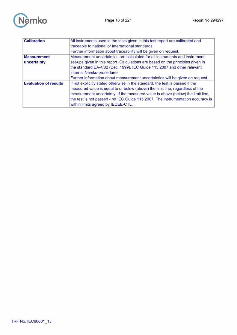
Calibration All instruments used in the tests given in this test report are calibrated and
traceable to national or international standards. Further information about traceability will be given on request.
Measurement uncertainty
Measurement uncertainties are calculated for all instruments and instrument set-ups given in this report. Calculations are based on the principles given in the standard EA-4/02 (Dec. 1999), IEC Guide 115:2007 and other relevant internal Nemko-procedures. Further information about measurement uncertainties will be given on request.
Evaluation of results If not explicitly stated otherwise in the standard, the test is passed if the measured value is equal to or below (above) the limit line, regardless of the measurement uncertainty. If the measured value is above (below) the limit line, the test is not passed - ref IEC Guide 115:2007. The instrumentation accuracy is within limits agreed by IECEE-CTL.

Page 17 of 221 Report No 294297
TRF No. IEC60601_1J
GENERAL INFORMATION
Test item particulars (see also Clause 6):
Classification of installation and use ................................. : Class II, PSU for building-in
Device type (component/sub-assembly/ equipment/ system) .................................................................................. :
Component, PSU for building-in
Intended use (Including type of patient, application location) ................................................................................ :
PSU for building-in
Mode of operation ............................................................... : Continuous
Supply connection .............................................................. : PSU for building-in
Accessories and detachable parts included ...................... : None
Other options include .......................................................... : None
Testing
Date of receipt of test item(s) ............................................... : September, 2015
Dates tests performed ........................................................... : July 2015 - August, 2015
Possible test case verdicts:
- test case does not apply to the test object ........................ : N/A
- test object does meet the requirement .............................. : Pass (P)
- test object was not evaluated for the requirement ................ : N/E (collateral standards only)
- test object does not meet the requirement ........................ : Fail (F)
Abbreviations used in the report: - normal condition ..................................................... : N.C. - single fault condition ................... : S.F.C. - means of Operator protection ................................ : MOOP - means of Patient protection ....... : MOPP
General remarks: "(See Attachment #)" refers to additional information appended to the report. "(See appended table)" refers to a table appended to the report. The tests results presented in this report relate only to the object tested. This report shall not be reproduced except in full without the written approval of the testing laboratory. List of test equipment must be kept on file and available for review. Additional test data and/or information provided in the attachments to this report. Throughout this report a comma / point is used as the decimal separator.
Manufacturer’s Declaration per sub-clause 4.2.5 of IECEE 02:
The application for obtaining a CB Test Certificate includes more than one factory location and a declaration from the Manufacturer stating that the sample(s) submitted for evaluation is (are) representative of the products from each factory has been provided ..................................................... :
Yes Not applicable
When differences exist; they shall be identified in the General product information section.
Name and address of factory (ies) ........................ : EOS Power India PVT Ltd. Unit #57, SDF II, Seepz-Sez, Andheri (East), Mumbai 400096, India
Page 18 of 221 Report No 294297
TRF No. IEC60601_1J
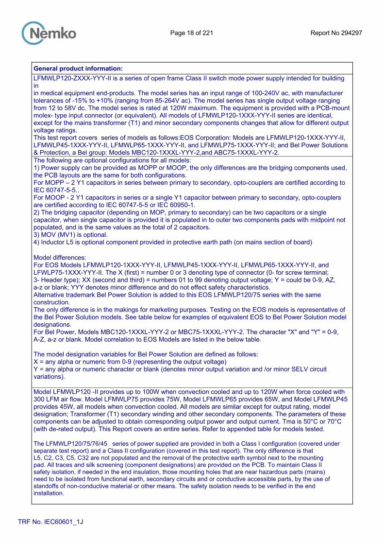
General product information:
LFMWLP120-ZXXX-YYY-II is a series of open frame Class II switch mode power supply intended for building in in medical equipment end-products. The model series has an input range of 100-240V ac, with manufacturer tolerances of -15% to +10% (ranging from 85-264V ac). The model series has single output voltage ranging from 12 to 58V dc. The model series is rated at 120W maximum. The equipment is provided with a PCB-mount molex- type input connector (or equivalent). All models of LFMWLP120-1XXX-YYY-II series are identical, except for the mains transformer (T1) and minor secondary components changes that allow for different output voltage ratings. This test report covers series of models as follows:EOS Corporation: Models are LFMWLP120-1XXX-YYY-II, LFMWLP45-1XXX-YYY-II, LFMWLP65-1XXX-YYY-II, and LFMWLP75-1XXX-YYY-II; and Bel Power Solutions & Protection, a Bel group: Models MBC120-1XXXL-YYY-2,and ABC75-1XXXL-YYY-2. The following are optional configurations for all models: 1) Power supply can be provided as MOPP or MOOP, the only differences are the bridging components used, the PCB layouts are the same for both configurations. For MOPP – 2 Y1 capacitors in series between primary to secondary, opto-couplers are certified according to IEC 60747-5-5.. For MOOP - 2 Y1 capacitors in series or a single Y1 capacitor between primary to secondary, opto-couplers are certified according to IEC 60747-5-5 or IEC 60950-1. 2) The bridging capacitor (depending on MOP, primary to secondary) can be two capacitors or a single capacitor, when single capacitor is provided it is populated in to outer two components pads with midpoint not populated, and is the same values as the total of 2 capacitors. 3) MOV (MV1) is optional. 4) Inductor L5 is optional component provided in protective earth path (on mains section of board) Model differences: For EOS Models LFMWLP120-1XXX-YYY-II, LFMWLP45-1XXX-YYY-II, LFMWLP65-1XXX-YYY-II, and LFWLP75-1XXX-YYY-II. The X (first) = number 0 or 3 denoting type of connector (0- for screw terminal; 3- Header type); XX (second and third) = numbers 01 to 99 denoting output voltage; Y = could be 0-9, AZ, a-z or blank; YYY denotes minor difference and do not effect safety characteristics. Alternative trademark Bel Power Solution is added to this EOS LFMWLP120/75 series with the same construction. The only difference is in the makings for marketing purposes. Testing on the EOS models is representative of the Bel Power Solution models. See table below for examples of equivalent EOS to Bel Power Solution model designations. For Bel Power, Models MBC120-1XXXL-YYY-2 or MBC75-1XXXL-YYY-2. The character "X" and "Y" = 0-9, A-Z, a-z or blank. Model correlation to EOS Models are listed in the below table. The model designation variables for Bel Power Solution are defined as follows: X = any alpha or numeric from 0-9 (representing the output voltage) Y = any alpha or numeric character or blank (denotes minor output variation and /or minor SELV circuit variations). Model LFMWLP120 -II provides up to 100W when convection cooled and up to 120W when force cooled with 300 LFM air flow. Model LFMWLP75 provides 75W, Model LFMWLP65 provides 65W, and Model LFMWLP45 provides 45W, all models when convection cooled. All models are similar except for output rating, model designation; Transformer (T1) secondary winding and other secondary components. The parameters of these components can be adjusted to obtain corresponding output power and output current. Tma is 50°C or 70°C (with de-rated output). This Report covers an entire series. Refer to appended table for models tested. The LFMWLP120/75/76/45 series of power supplied are provided in both a Class I configuration (covered under separate test report) and a Class II configuration (covered in this test report). The only difference is that L5, C2, C3, C5, C32 are not populated and the removal of the protective earth symbol next to the mounting pad. All traces and silk screening (component designations) are provided on the PCB. To maintain Class II safety isolation, if needed in the end insulation, those mounting holes that are near hazardous parts (mains) need to be isolated from functional earth, secondary circuits and or conductive accessible parts, by the use of standoffs of non-conductive material or other means. The safety isolation needs to be verified in the end installation.

Page 19 of 221 Report No 294297
TRF No. IEC60601_1J
General product information: These are component power supply intended for building-in Class I or Class II end-products. The MWLP series has single output versions whose voltage can be from 12VDC to 58VDC.The power supplies deliver full power up to +50°C and will operate at up to +70°C with derating. LFMWLP120 provides up to 100W when convection cooled and up to 120 W when force cooled with 300 LFM air flow applied to inductor L3 inward. The LFMWLP75 provides 75W when convection cooled. Condition Voltage Current Load Input range Colling Tma (°C) Output Status used Model LFMWLP120-1001-II (Rated 3.0A max., 100-240Vac, 47-63 Hz)
A 12.0 10 85-264V~ 300LFM 50 Forced B 5 85-264V~ 300LFM 70 Forced C 8.33 100-264V~ Natural 50 D 4.17 100-264V~ Natural 70
E 6.67 85 -<100V~ Natural 50 F 3.33 85 -<100V~ Natural 70
LFMWLP120-1006-II ((Rated 3.0A max., 100-240Vac, 47-63 Hz) G 58.0 2.07 85-264V~ 300LFM 50 Forced H 1.03 85-264V~ 300LFM 70 Forced I 1.72 100-264V~ Natural 50
J 0.86 100-264V~ Natural 70 K 1.38 85 -<100V~ Natural 50
L 0.69 85 -<100V~ Natural 70
LFMWLP75-1001 –II (Rated 2.0A max., 100-240Vac, 47-63 Hz)
A1 12.0 6.25 100-264V~ Natural 50 B1 3.13 100-264V~ Natural 70
C1 5.42 85 -<100V~ Natural 50
D1 2.71 85 -<100V~ Natural 70
LFMWLP75-1006-II (Rated 2.0A max., 100-240Vac, 47-63 Hz) E1 58.0 1.29 100-264V~ Natural 50
F1 0.65 100-264V~ Natural 70
G1 1.12 85 -<100V~ Natural 50 H1 0.56 85 -<100V~ Natural 70

Page 20 of 221 Report No 294297
TRF No. IEC60601_1J
General product information: Letter references in the above table (A to H1) indicates loading condition as noted in the table below. Mentioned below is representative Model Ratings Table for 50°C ambient with 300 LFM air flow from Boost inductor L3.Derated power ratings at 70°C ambient are also specified below: The alphabets in parenthesis represent the overall series loading. Model: LFMWLP120-ZXXX-YYY-II Output Ratings for Input range: 85Vac-264Vac
MODEL
Maximum Individual Continuous Power with 300LFM Forced Air flow & Power Derating at Elevated Temperatures
Voltage 50˚C 70˚C Volts Watts Watts
LFMWLP120-1001-II 12 120(A) 60(B) LFMWLP120-1002-II 15 120 60 LFMWLP120-1003-II 24 120 60 LFMWLP120-1004-II 48 120 60 LFMWLP120-1005-II 30 120 60 LFMWLP120-1006-II 58 120(G) 60(H)
Output Ratings for Convection Cooling
MODEL
Input range: 100Vac-264Vac Maximum Individual Continuous Power with Convection cooling & Power Derating at Elevated Temperatures
Input range: 85Vac - <100Vac Maximum Individual Continuous Power with Convection cooling & Power Derating at Elevated Temperatures
Voltage 50˚C 70˚C 50˚C 70˚C Volts Watts Watts Watts Watts
LFMWLP120-1001-II 12 100(C) 50(D) 80(E) 40(F) LFMWLP120-1002-II 15 100 50 80 40 LFMWLP120-1003-II 24 100 50 80 40 LFMWLP120-1004-II 48 100 50 80 40 LFMWLP120-1005-II 30 100 50 80 40 LFMWLP120-1006-II 58 100(I) 50(J) 80(K) 40 (L)
Model: LFMWLP75-ZXXX-YYY-II Output Ratings for Input range: 100 - 264Vac
MODEL
Maximum Individual Continuous Power with Convection cooling & Power Derating at Elevated Temperatures
Voltage 50˚C 70˚C Volts Watts Watts
LFMWLP75-1001-II 12 75(A1) 37.5(B1) LFMWLP75-1002-II 15 75 37.5 LFMWLP75-1003-II 24 75 37.5 LFMWLP75-1004-II 48 75 37.5 LFMWLP75-1005-II 30 75 37.5 LFMWLP75-1006-II 58 75(E1) 37.5 (F1)

Page 21 of 221 Report No 294297
TRF No. IEC60601_1J
General product information: Output Ratings for Input range: 85 - <100Vac
MODEL
Maximum Individual Continuous Power with Convection cooling & Power Derating at Elevated Temperatures
Voltage 50˚C 70˚C Volts Watts Watts
LFMWLP75-1001-II 12 65(C1) 32.5(D1) LFMWLP75-1002-II 15 65 32.5 LFMWLP75-1003-II 24 65 32.5 LFMWLP75-1004-II 48 65 32.5 LFMWLP75-1005-II 30 65 32.5 LFMWLP75-1006-II 58 65 (G1) 32.5 (H1)
The clearance distances have additionally been assessed for suitability up to 5000m elevation. All models have identical schematic and PWB layout
EOS Voltage Current
Custom Bel
Model Number Connector Part Suffix Part Number
LFMWLP120-1001-II Screw Terminal 12V 10A MBC120-1T12L-2
LFMWLP120-1301-II Header MBC120-1012L-2
LFMWLP120-1002-II Screw Terminal 15V 8A MBC120-1T15L-2
LFMWLP120-1302-II Header MBC120-1015L-2
LFMWLP120-1003-II Screw Terminal 24V 5A MBC120-1T24L-2
LFMWLP120-1303-II Header MBC120-1024L-2
LFMWLP120-1004-II Screw Terminal 48V 2.5A MBC120-1T48L-2
LFMWLP120-1304-II Header MBC120-1048L-2
LFMWLP120-1005-II Screw Terminal 30V 4A MBC120-1T30L-2
LFMWLP120-1305-II Header MBC120-1030L-2
LFMWLP120-1006-II Screw Terminal 58V 2.06A MBC120-1T58L-2
LFMWLP120-1306-II Header MBC120-1058L-2
LFMWLP75-1001-II Screw Terminal 12V 6.25A MBC75-1T12L-2
LFMWLP75-1301-II Header MBC75-1012L-2

Page 22 of 221 Report No 294297
TRF No. IEC60601_1J
LFMWLP75-1002-II Screw Terminal 15V 5.00A MBC75-1T15L-2
LFMWLP75-1302-II Header MBC75-1015L-2
LFMWLP75-1003-II Screw Terminal 24V 3.13A MBC75-1T24L-2
LFMWLP75-1303-II Header MBC75-1024L-2
LFMWLP75-1004-II Screw Terminal 48V 1.56A MBC75-1T48L-2
LFMWLP75-1304-II Header MBC75-1048L-2
LFMWLP75-1005-II Screw Terminal 30V 2.50A MBC75-1T30L-2
LFMWLP75-1305-II Header MBC75-1030L-2
LFMWLP75-1006-II Screw Terminal 58V 1.29A MBC75-1T58L-2
LFMWLP75-1306-II Header MBC75-1058L-2
LFMWLP65-1001-II Screw Terminal 12V 5.42A
LFMWLP65-1301-II Header
LFMWLP65-1002-II Screw Terminal 15V 4.33A
LFMWLP65-1302-II Header
LFMWLP65-1003-II Screw Terminal 24V 2.71A
LFMWLP65-1303-II Header
LFMWLP65-1004-II Screw Terminal 48V 1.35A
LFMWLP65-1304-II Header
LFMWLP65-1005-II Screw Terminal 30V 2.17A
LFMWLP65-1305-II Header
LFMWLP65-1006-II Screw Terminal 58V 1.12A
LFMWLP65-1306-II Header
LFMWLP45-1001-II Screw Terminal 12V 3.75A
LFMWLP45-1301-II Header
LFMWLP45-1002-II Screw Terminal 15V 3.00A

Page 23 of 221 Report No 294297
TRF No. IEC60601_1J
LFMWLP45-1302-II Header
LFMWLP45-1003-II Screw Terminal 24V 1.88A
LFMWLP45-1303-II Header
LFMWLP45-1004-II Screw Terminal 48V 0.94A
LFMWLP45-1304-II Header
LFMWLP45-1005-II Screw Terminal 30V 1.50A
LFMWLP45-1305-II Header
LFMWLP45-1006-II Screw Terminal 58V 0.78A
LFMWLP45-1306-II Header