Embed Size (px)
Citation preview
ATTACHMENT III PAGE 1 OF 12
REGIONAL PROGRAM 14R02-S1
CPR © 2016 FORD MOTOR COMPANYDEARBORN, MICHIGAN 481214/2016
CERTAIN 2007 THROUGH 2008 MODEL YEAR EDGE AND MKX VEHICLES — FUEL TANK CORROSION INSPECTION AND REPAIR
OVERVIEW In some of the affected vehicles that are operated in high-corrosion environments associated with road salt use, moisture and salt may become trapped under the fuel tank mounting reinforcement brackets at the four corners where the fuel tank is attached to the vehicle. Over time, corrosion under these reinforcement brackets can spread to the fuel tank which can result in a fuel leak. A fuel leak in the presence of an ignition source may result in a fire.
SERVICE PROCEDURE
WARNING: Do not smoke, carry lighted tobacco or have an open flame of any type when working on or near any fuel-related component. Highly flammable mixtures are always present and may be ignited. Failure to follow these instructions may result in serious personal injury.
WARNING: Do not carry personal electronic devices such as cell phones, pagers or audio equipment of any type when working on or near any fuel-related component. Highly flammable mixtures are always present and may be ignited. Failure to follow these instructions may result in serious personal injury.
WARNING: Before working on or disconnecting any of the fuel tubes or fuel system components, relieve the fuel system pressure to prevent accidental spraying of fuel. Fuel in the fuel system remains under high pressure, even when the engine is not running. Failure to follow this instruction may result in serious personal injury.
WARNING: Remove the fuel filler cap slowly. The fuel system may be under pressure. If the fuel filler cap is venting vapor or if you hear a hissing sound, wait until it stops before completely removing the fuel filler cap. Otherwise, fuel may spray out. Failure to follow these instructions may result in serious personal injury.
WARNING: When handling fuel, always observe fuel handling precautions and be prepared in the event of fuel spillage. Spilled fuel may be ignited by hot vehicle components or other ignition sources. Failure to follow these instructions may result in serious personal injury.
Fuel Tank Removal Procedure
All Vehicles
1. Position vehicle on a hoist. Please follow Workshop Manual (WSM) procedures in Section 100-02.
2. Check fuel level indication on instrument cluster and drain fuel if needed.
- If less than 1/2 tank, it is not necessary to drain fuel. Continue to Step 3. - If more than 1/2 tank, drain fuel to attain less than 1/2 tank as follows: a. Remove fuel tank filler cap and position it aside. b. Insert a suitable fuel drain tube into the fuel tank filler pipe until it enters the fuel tank. c. Attach a fuel storage tanker to the drain tube and drain fuel to bring fuel level below 1/2 tank.
ATTACHMENT III PAGE 2 OF 12
REGIONAL PROGRAM 14R02-S1
CPR © 2016 FORD MOTOR COMPANYDEARBORN, MICHIGAN 481214/2016
3. Release the fuel system pressure. Please follow WSM procedures in Section 310-00.
4. Disconnect the battery ground cable. Please follow WSM procedures in Section 414-01.
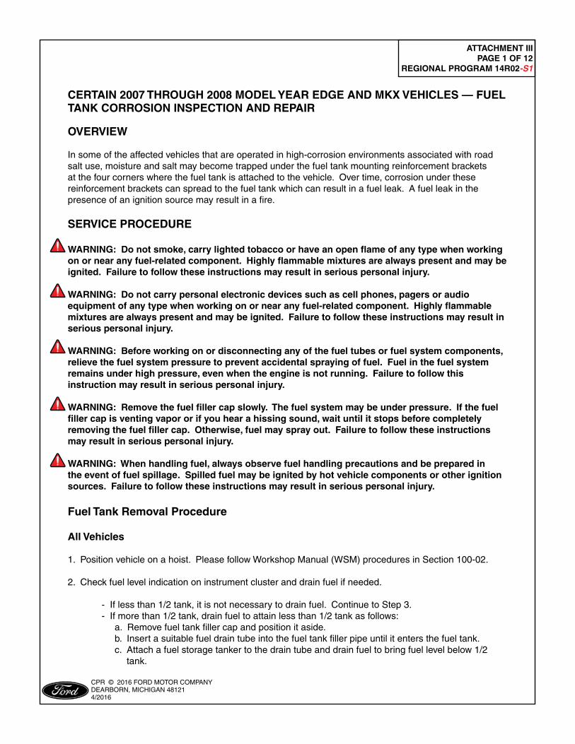
5. Lower or remove the muffler and tailpipe as follows:
NOTE: Do not damage or tear the isolators during removal. Do not use oil or grease-based lubricants on the isolators. They may cause deterioration of the rubber. Use soapy water as needed to separate the isolators from the vehicle.
Front Wheel Drive (FWD) Vehicles a. Detach the three (3) muffler and tailpipe assembly rear isolators. See Figure 1. b. Position the rear of the exhaust system down approximately 305 mm (12 in) and support using a jack stand.
FIGURE 1
PLACE COPY HERE
PLACE COPY HERE
PLACE COPY HERE
STUD FORMISSING NUT
STUD FORMISSING NUT
STUD FORMISSING NUT
1453R
FRONT OFVEHICLE
ATTACHMENT III PAGE 3 OF 12
REGIONAL PROGRAM 14R02-S1
CPR © 2016 FORD MOTOR COMPANYDEARBORN, MICHIGAN 481214/2016
FIGURE 2
PLACE COPY HERE
PLACE COPY HERE
PLACE COPY HERE
STUD FORMISSING NUT
STUD FORMISSING NUT
STUD FORMISSING NUT
1453Z
FRONT OFVEHICLE
TORCA® CLAMP
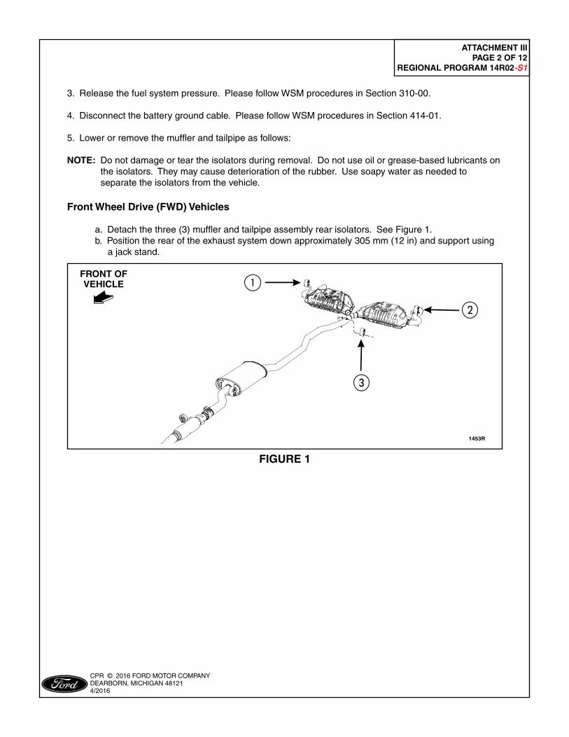
All Wheel Drive (AWD) Vehicles
a. Detach the four (4) muffler and tailpipe assembly isolators. See Figure 2. b. Loosen the Torca® clamp and remove the exhaust system from the vehicle.
NOTE: Install a new Torca® clamp, if necessary, following the procedures in Section 309-00.
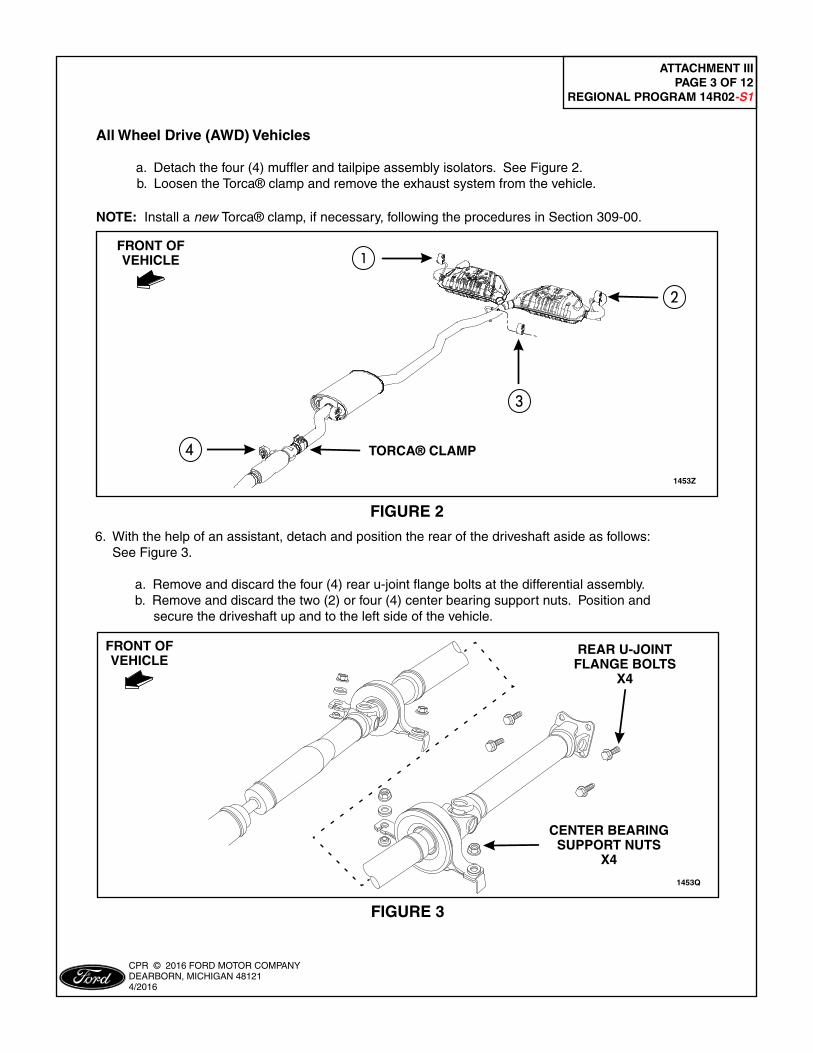
6. With the help of an assistant, detach and position the rear of the driveshaft aside as follows: See Figure 3.
a. Remove and discard the four (4) rear u-joint flange bolts at the differential assembly. b. Remove and discard the two (2) or four (4) center bearing support nuts. Position and secure the driveshaft up and to the left side of the vehicle.
FIGURE 3
PLACE COPY HERE
PLACE COPY HERE
PLACE COPY HERE
STUD FORMISSING NUT
STUD FORMISSING NUT
STUD FORMISSING NUT
1453Q
REAR U-JOINTFLANGE BOLTS
X4
CENTER BEARINGSUPPORT NUTS
X4
FRONT OFVEHICLE
ATTACHMENT III PAGE 4 OF 12
REGIONAL PROGRAM 14R02-S1
CPR © 2016 FORD MOTOR COMPANYDEARBORN, MICHIGAN 481214/2016
All Vehicles
7. Install a suitable lifting device under the fuel tank.
8. Disconnect the fuel tank wiring harness electrical connector.
9. Disconnect the Fuel Tank Pressure (FTP) sensor electrical connector.
10. Disconnect the fuel vapor tube assembly-to-fuel tank quick connect coupling. Please follow WSM procedures in Section 310-00.
11. Release the clamp and disconnect the fuel tank filler pipe hose from the fuel tank.
12. Disconnect the fuel tank jumper tube-to-fuel tube quick connect coupling. Please follow WSM procedures in Section 310-00.
13. Remove the two (2) parking brake cable bracket bolts and position cables aside.
NOTICE: Position the lifting device securely against the fuel tank prior to loosening any fuel tank attaching bolts.
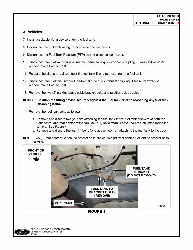
14. Remove the fuel tank bolts as follows:
a. Remove and discard two (2) bolts attaching the fuel tank to the fuel tank brackets at both the front center and rear center of the tank (four (4) bolts total). Leave the brackets attached to the vehicle. See Figure 4. b. Remove and discard the four (4) bolts (one at each corner) attaching the fuel tank to the body.
NOTE: Two (2) rear center fuel tank to bracket bolts shown, two (2) front center fuel tank to bracket bolts similar.
FIGURE 4
PLACE COPY HERE
PLACE COPY HERE
PLACE COPY HERE
STUD FORMISSING NUT
STUD FORMISSING NUT
STUD FORMISSING NUT
1453AA
FUEL TANK BRACKET
(DO NOT REMOVE)
FUEL TANK TO BRACKET BOLTS
(REMOVE)
FRONT OFVEHICLE
FUEL TANK
ATTACHMENT III PAGE 5 OF 12
REGIONAL PROGRAM 14R02-S1
CPR © 2016 FORD MOTOR COMPANYDEARBORN, MICHIGAN 481214/2016
NOTE: AWD vehicles require the fuel tank to be positioned forward, past the Rear Differential Unit (RDU), then lowered. FWD vehicles require the fuel tank be partially lowered onto a 102 mm (4 in) by 102 mm (4 in) piece of lumber (or equivalent) placed under the right side of the tank and then lifted and lowered over the exhaust and out the drivers side of the vehicle.
15. Remove the fuel tank. Continue to Fuel Tank Inspection Procedure on Page 6.
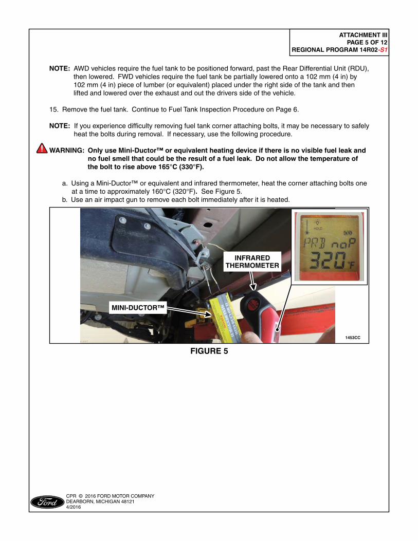
NOTE: If you experience difficulty removing fuel tank corner attaching bolts, it may be necessary to safely heat the bolts during removal. If necessary, use the following procedure.
WARNING: Only use Mini-Ductor™ or equivalent heating device if there is no visible fuel leak and no fuel smell that could be the result of a fuel leak. Do not allow the temperature of the bolt to rise above 165°C (330°F).
a. Using a Mini-Ductor™ or equivalent and infrared thermometer, heat the corner attaching bolts one at a time to approximately 160°C (320°F). See Figure 5. b. Use an air impact gun to remove each bolt immediately after it is heated.
FIGURE 5
1453CC
INFRAREDTHERMOMETER
MINI-DUCTOR™
ATTACHMENT III PAGE 6 OF 12
REGIONAL PROGRAM 14R02-S1
CPR © 2016 FORD MOTOR COMPANYDEARBORN, MICHIGAN 481214/2016
Fuel Tank Inspection Procedure
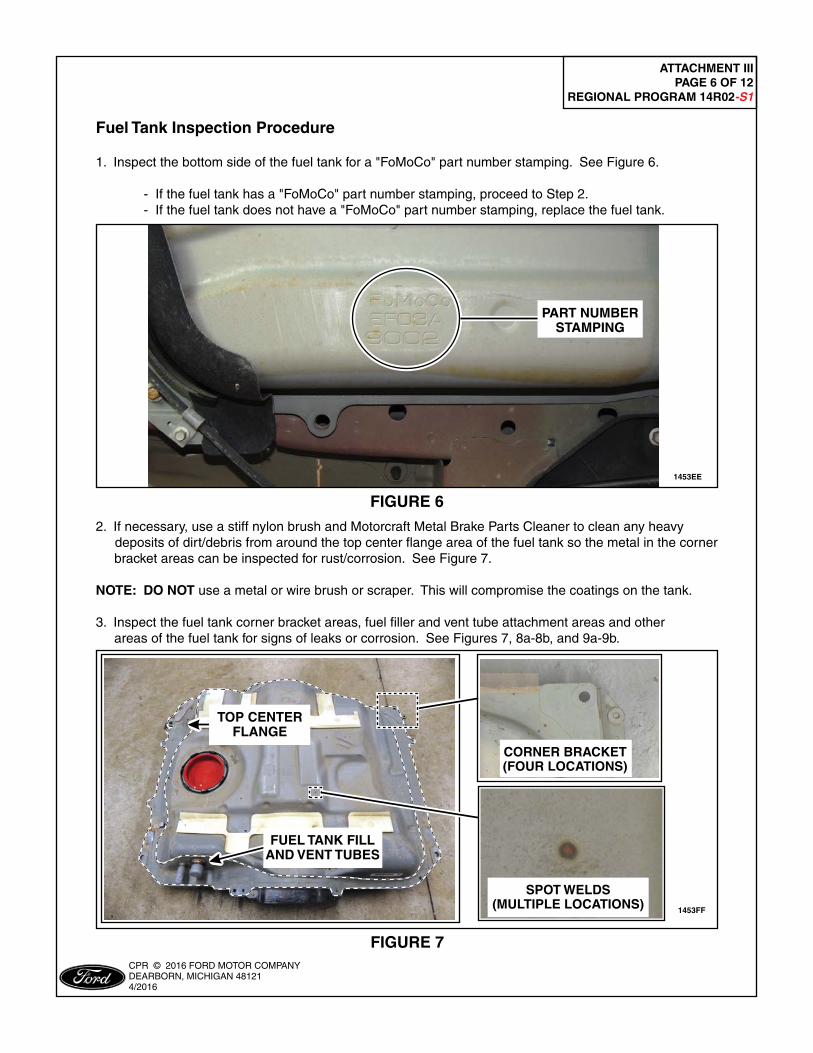
1. Inspect the bottom side of the fuel tank for a "FoMoCo" part number stamping. See Figure 6.
- If the fuel tank has a "FoMoCo" part number stamping, proceed to Step 2. - If the fuel tank does not have a "FoMoCo" part number stamping, replace the fuel tank.
FIGURE 6
1453EE
PART NUMBERSTAMPING
2. If necessary, use a stiff nylon brush and Motorcraft Metal Brake Parts Cleaner to clean any heavy deposits of dirt/debris from around the top center flange area of the fuel tank so the metal in the corner bracket areas can be inspected for rust/corrosion. See Figure 7.
NOTE: DO NOT use a metal or wire brush or scraper. This will compromise the coatings on the tank. 3. Inspect the fuel tank corner bracket areas, fuel filler and vent tube attachment areas and other areas of the fuel tank for signs of leaks or corrosion. See Figures 7, 8a-8b, and 9a-9b.
FIGURE 7
PLACE COPY HERE
PLACE COPY HERE
PLACE COPY HERE
STUD FORMISSING NUT
STUD FORMISSING NUT
STUD FORMISSING NUT
1453FF
FUEL TANK FILL AND VENT TUBES
CORNER BRACKET(FOUR LOCATIONS)
SPOT WELDS(MULTIPLE LOCATIONS)
TOP CENTERFLANGE
ATTACHMENT III PAGE 7 OF 12
REGIONAL PROGRAM 14R02-S1
CPR © 2016 FORD MOTOR COMPANYDEARBORN, MICHIGAN 481214/2016
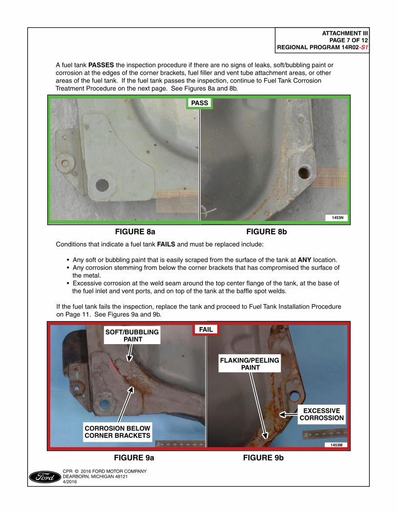
A fuel tank PASSES the inspection procedure if there are no signs of leaks, soft/bubbling paint or corrosion at the edges of the corner brackets, fuel filler and vent tube attachment areas, or other areas of the fuel tank. If the fuel tank passes the inspection, continue to Fuel Tank Corrosion Treatment Procedure on the next page. See Figures 8a and 8b.
FIGURE 8a FIGURE 8b
FIGURE 9a FIGURE 9b
PLACE COPY HERE
PLACE COPY HERE
PLACE COPY HERE
STUD FORMISSING NUT
STUD FORMISSING NUT
STUD FORMISSING NUT
1453M
SOFT/BUBBLING PAINT
FAIL
CORROSION BELOWCORNER BRACKETS
FLAKING/PEELING PAINT
EXCESSIVECORROSSION
PLACE COPY HERE
PLACE COPY HERE
PLACE COPY HERE
STUD FORMISSING NUT
STUD FORMISSING NUT
STUD FORMISSING NUT
1453N
PASS
Conditions that indicate a fuel tank FAILS and must be replaced include:
• Any soft or bubbling paint that is easily scraped from the surface of the tank at ANY location. • Any corrosion stemming from below the corner brackets that has compromised the surface of the metal. • Excessive corrosion at the weld seam around the top center flange of the tank, at the base of the fuel inlet and vent ports, and on top of the tank at the baffle spot welds.
If the fuel tank fails the inspection, replace the tank and proceed to Fuel Tank Installation Procedure on Page 11. See Figures 9a and 9b.
ATTACHMENT III PAGE 8 OF 12
REGIONAL PROGRAM 14R02-S1
CPR © 2016 FORD MOTOR COMPANYDEARBORN, MICHIGAN 481214/2016
Fuel Tank Corrosion Treatment Procedure
1. Using a stiff nylon brush and Motorcraft Metal Brake Parts Cleaner, clean the top surface area of all four (4) corner brackets and surrounding area of the center tank flange.
NOTE: DO NOT use a metal or wire brush or scraper. This will compromise the coatings on the tank.
2. Clean the area around the fuel fill and vent tubes.
3. Clean the spot welds on top of the tank.
4. Wipe clean with shop towel.
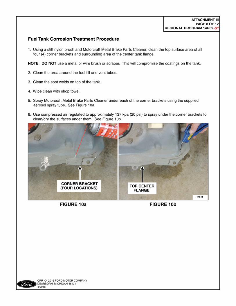
5. Spray Motorcraft Metal Brake Parts Cleaner under each of the corner brackets using the supplied aerosol spray tube. See Figure 10a.
6. Use compressed air regulated to approximately 137 kpa (20 psi) to spray under the corner brackets to clean/dry the surfaces under them. See Figure 10b.
FIGURE 10a FIGURE 10b
PLACE COPY HERE
PLACE COPY HERE
PLACE COPY HERE
STUD FORMISSING NUT
STUD FORMISSING NUT
STUD FORMISSING NUT
1453T
CORNER BRACKET(FOUR LOCATIONS) TOP CENTER
FLANGE
ATTACHMENT III PAGE 9 OF 12
REGIONAL PROGRAM 14R02-S1
CPR © 2016 FORD MOTOR COMPANYDEARBORN, MICHIGAN 481214/2016
9. Repeat spraying a second application of anti-corrosion treatment under each of the corner brackets but DO NOT use compressed air on the second application.
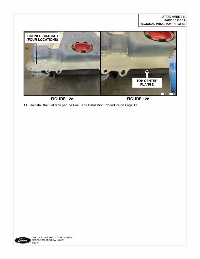
NOTE: Before applying anti-corrosion treatment to the fuel tank surface, cover the filler neck and vent tube with a suitable cover to keep these areas free of the treatment. See Figure 12a.
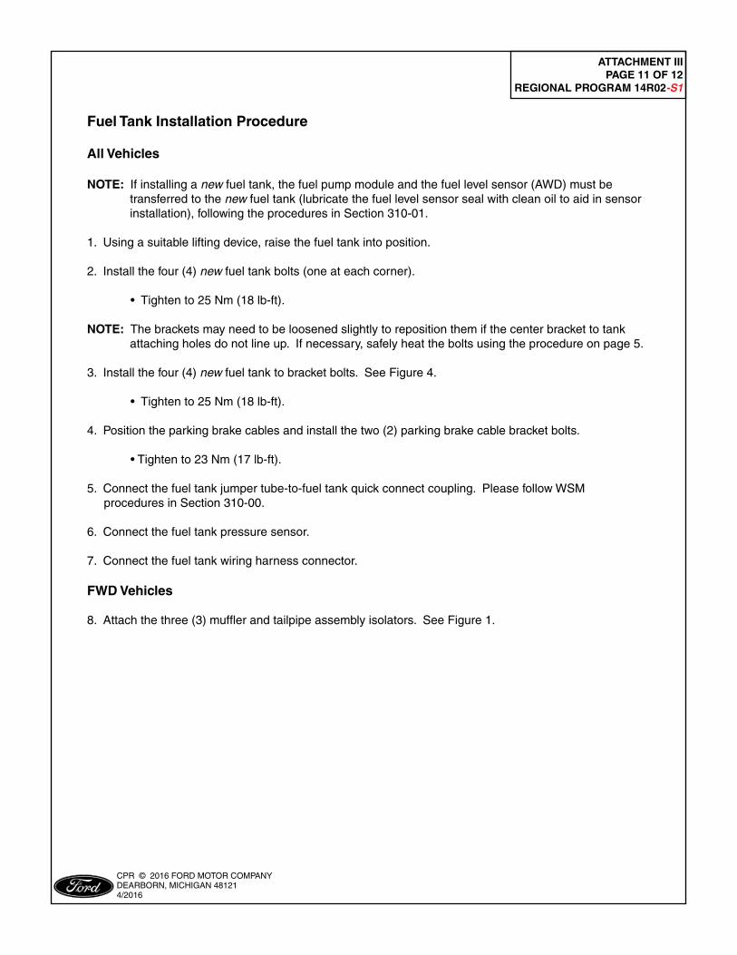
10. Remove the aerosol tube and apply a heavy coat of anti-corrosion treatment over the following areas of the fuel tank: See Figures 7 and 12a-12d.
a. Around the fill and vent tubes. b. All spot welds on top of the tank. c. Corner bracket areas. d. On the top center flange around the entire perimeter of the tank.
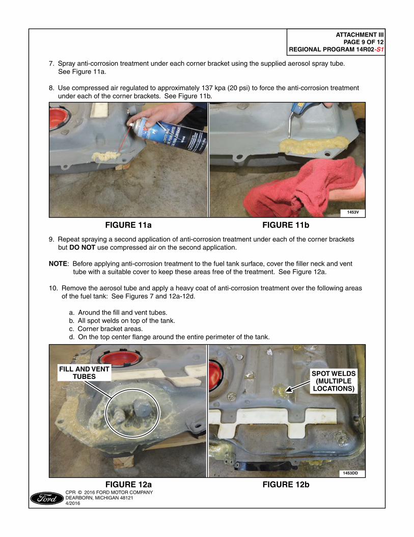
7. Spray anti-corrosion treatment under each corner bracket using the supplied aerosol spray tube. See Figure 11a.
8. Use compressed air regulated to approximately 137 kpa (20 psi) to force the anti-corrosion treatment under each of the corner brackets. See Figure 11b.
FIGURE 11a FIGURE 11b
PLACE COPY HERE
PLACE COPY HERE
PLACE COPY HERE
STUD FORMISSING NUT
STUD FORMISSING NUT
STUD FORMISSING NUT
1453V
FIGURE 12a FIGURE 12b
1453DD
PLACE COPY HERE
PLACE COPY HERE
PLACE COPY HERE
STUD FORMISSING NUT
STUD FORMISSING NUT
STUD FORMISSING NUT
FILL AND VENTTUBES SPOT WELDS
(MULTIPLELOCATIONS)
ATTACHMENT III PAGE 10 OF 12
REGIONAL PROGRAM 14R02-S1
CPR © 2016 FORD MOTOR COMPANYDEARBORN, MICHIGAN 481214/2016
FIGURE 12c FIGURE 12d
PLACE COPY HERE
PLACE COPY HERE
PLACE COPY HERE
STUD FORMISSING NUT
STUD FORMISSING NUT
STUD FORMISSING NUT
CORNER BRACKET(FOUR LOCATIONS)
1453X
TOP CENTERFLANGE
11. Reinstall the fuel tank per the Fuel Tank Installation Procedure on Page 11.
ATTACHMENT III PAGE 11 OF 12
REGIONAL PROGRAM 14R02-S1
CPR © 2016 FORD MOTOR COMPANYDEARBORN, MICHIGAN 481214/2016
Fuel Tank Installation Procedure
All Vehicles
NOTE: If installing a new fuel tank, the fuel pump module and the fuel level sensor (AWD) must be transferred to the new fuel tank (lubricate the fuel level sensor seal with clean oil to aid in sensor installation), following the procedures in Section 310-01. 1. Using a suitable lifting device, raise the fuel tank into position.
2. Install the four (4) new fuel tank bolts (one at each corner).
• Tighten to 25 Nm (18 lb-ft).
NOTE: The brackets may need to be loosened slightly to reposition them if the center bracket to tank attaching holes do not line up. If necessary, safely heat the bolts using the procedure on page 5.
3. Install the four (4) new fuel tank to bracket bolts. See Figure 4.
• Tighten to 25 Nm (18 lb-ft).
4. Position the parking brake cables and install the two (2) parking brake cable bracket bolts.
• Tighten to 23 Nm (17 lb-ft).
5. Connect the fuel tank jumper tube-to-fuel tank quick connect coupling. Please follow WSM procedures in Section 310-00.
6. Connect the fuel tank pressure sensor.
7. Connect the fuel tank wiring harness connector.
FWD Vehicles
8. Attach the three (3) muffler and tailpipe assembly isolators. See Figure 1.
ATTACHMENT III PAGE 12 OF 12
REGIONAL PROGRAM 14R02-S1
CPR © 2016 FORD MOTOR COMPANYDEARBORN, MICHIGAN 481214/2016
AWD Vehicles
9. Position the driveshaft and install the two (2) or four (4) new center bearing support nuts. See Figure 3.
• Tighten to 40 Nm (30 lb-ft).
10. Position the driveshaft and install the four (4) new rear u-joint flange bolts. See Figure 3. • Tighten to 70 Nm (52 lb-ft).
NOTE: Install a new Torca® clamp, if necessary, following WSM procedures in Section 309-00.
11. Install the muffler and tailpipe assembly and attach the four (4) isolators. See Figure 2.
All Vehicles
12. Connect the battery ground cable. Please follow WSM procedures in Section 414-01.