Embed Size (px)
Citation preview
Digital Object Identifier (DOI) 10.1140/epjc/s2004-01762-0Eur. Phys. J. C 34, 15–23 (2004) THE EUROPEAN
PHYSICAL JOURNAL C
CERN’s contribution to accelerators and beamsG. Brianti
Formerly CERN
5 Chemin des Tulipiers, 1208 Geneva, Switzerland
Received: 15 December 2003 /Published online: 4 May 2004 – c© 2003 Giorgio Brianti
1 Introduction
Looking back at happy events of the past, the temptationis to see them with the magnifying glasses of the “goodold times”. In the cases of the discoveries that we cele-brate today, I dare say that CERN’s contributions to ac-celerators and beams were objectively important and evenessential. Indeed, it was more than competent masteringof well proven techniques of beam acceleration, beam stor-ing and beam handling. Of course, it needed all this, evenbrought to extremes, but the additional decisive touch wasdue to real inventions and to techniques used for the firsttime.
Today, I am proud to represent here the CERN acce-lerator community of that time. I am one of many, who,particularly in the case of the proton–antiproton project,worked enthusiastically for supplying the beams leadingto the discovery of W ’s and Z’s.
I will concentrate on:– particle focusing, the Magnetic Horn;– beam intensity enhancement, the PS Booster;– proton–proton collisions, the ISR;– proton–antiproton collisions, made possible by the sto-
chastic beam cooling, and the entire proton–antiprotoncomplex;
– LEP and LHC.
2 Magnetic horn
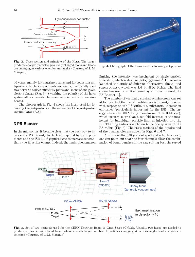
In 1961 S. van der Meer (Fig. 1) invented a device calledthe “Magnetic Horn”, which helped a great deal to fo-cus the particles emerging from a target, with the resultof vastly enhanced flux at the detector, in particular ofneutrinos. One can call it a “current sheet lens” since itproduces a highly focusing magnetic field in a space ofcylindrical symmetry by a kind of coaxial line with a hol-low central conductor, made of a thin aluminium sheet(Fig. 2). The current is in the range 100 to 400 kA in or-der to reach magnetic fields of several Tesla. Therefore,
Giorgio Brianti
the horn must be pulsed (half-sine wave of about 15 µs)to avoid excessive heating. The geometrical configurationand wall thickness can be easily adapted to the beam en-ergy and to the application. Horns have been in use for
Fig. 1. S. van der Meer describing the Horn to visitors
16 G. Brianti: CERN’s contribution to accelerators and beams
B ∝ I/RR
B
Coaxial current sheets
Inner conductor (2mm Al)
x
Cylindrical outer conductor
Fig. 2. Cross-section and principle of the Horn. The targetproduces charged particles: positively charged pions and kaonsare emerging at various energies and angles (Courtesy of J.-M.Maugain)
40 years, mainly for neutrino beams and for collecting an-tiprotons. In the case of neutrino beams, one usually usestwo horns to collect efficiently pions and kaons of one givenelectric charge (Fig. 3). Switching the polarity of the hornsystem allows to switch between neutrino and antineutrinobeams.
The photograph in Fig. 4 shows the Horn used for fo-cussing the antiprotons at the entrance of the AntiprotonAccumulator (AA).
3 PS Booster
In the mid sixties, it became clear that the best way to in-crease the PS intensity to the level required by the experi-ments and the ISR (1013 p/pulse) was to increase substan-tially the injection energy. Indeed, the main phenomenon
Fig. 4. Photograph of the Horn used for focusing antiprotons
limiting the intensity was incoherent or single particletune shift, which scales like (beta)2(gamma)3. P. Germainlaunched the study of different alternatives (linacs andsynchrotrons), which was led by H.K. Reich. The finalchoice favoured a multi-channel synchrotron, named thePS Booster [1].
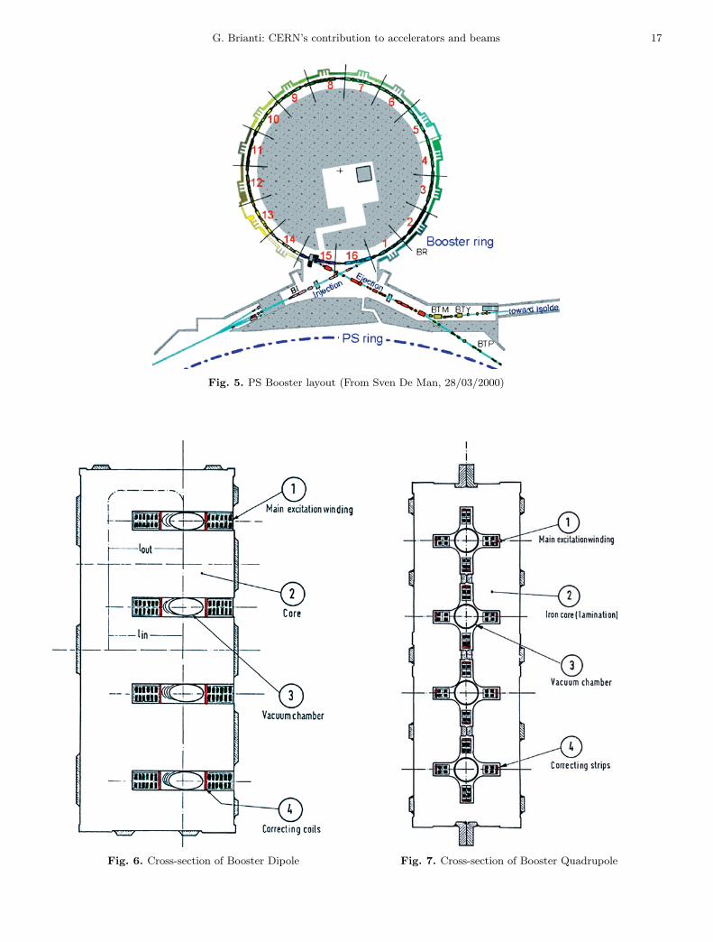
The number of vertically stacked synchrotrons was setat four, each of them able to obtain a 2.5 intensity increasewith respect to the PS without a substantial increase inemittance (particularly important for the ISR). The en-ergy was set at 800 MeV (a momemtum of 1463 MeV/c),which ensured more than a ten-fold increase of the inco-herent (or individual) particle limit at injection into thePS. The ring radius was chosen to be one quarter of thePS radius (Fig. 5). The cross-sections of the dipoles andof the quadrupoles are shown in Figs. 6 and 7.
After more than 30 years of good and reliable service,one can point out that the four channels allow the combi-nation of beam bunches in the way suiting best the served
150 kA (CNGS) 180 kA (CNGS)
50 GeV22 GeV35 GeV
Protons 450 GeV flux amplificationin detector > 10
Target
TargetHorn 1
Horn 2(reflector) Decay tunnel
(Generally vacuum tube)
Fig. 3. Set of two horns as used for the CERN Neutrino Beam to Gran Sasso (CNGS). Usually, two horns are needed toproduce a parallel wide band beam where a much larger number of particles emerging at various angles and energies arecollected (Courtesy of J.-M. Maugain)
G. Brianti: CERN’s contribution to accelerators and beams 17
Fig. 5. PS Booster layout (From Sven De Man, 28/03/2000)
Fig. 6. Cross-section of Booster Dipole Fig. 7. Cross-section of Booster Quadrupole
18 G. Brianti: CERN’s contribution to accelerators and beams
SI
a)
b)
CPS
K2DSM2
K1 VSM3VSM1
VSM2
DSM1
K3
IV
III
II
I
Fig. 8. On the left is shown the arrangements of bunches ejected from Booster: a) twenty sequential bunches; b) two times fivevertically stacked bunches; on the right is shown the injection into the PS ring
machine. For example, 20 sequentially ejected bunches(Fig. 8a) or 2×10 bunches by vertically stacking bunchesfrom 2 Booster rings (Fig. 8b) for the production of an-tiprotons or even a single bunch per ring as required bythe LHC.
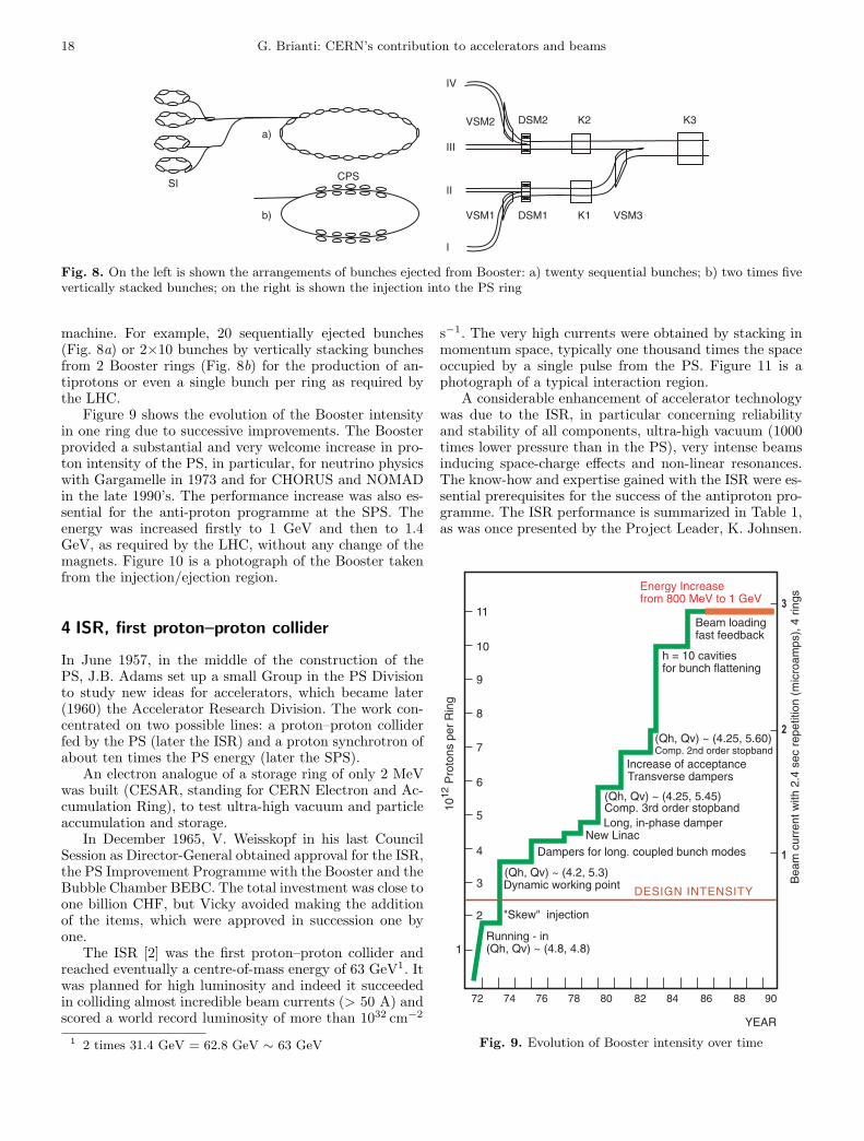
Figure 9 shows the evolution of the Booster intensityin one ring due to successive improvements. The Boosterprovided a substantial and very welcome increase in pro-ton intensity of the PS, in particular, for neutrino physicswith Gargamelle in 1973 and for CHORUS and NOMADin the late 1990’s. The performance increase was also es-sential for the anti-proton programme at the SPS. Theenergy was increased firstly to 1 GeV and then to 1.4GeV, as required by the LHC, without any change of themagnets. Figure 10 is a photograph of the Booster takenfrom the injection/ejection region.
4 ISR, first proton–proton collider
In June 1957, in the middle of the construction of thePS, J.B. Adams set up a small Group in the PS Divisionto study new ideas for accelerators, which became later(1960) the Accelerator Research Division. The work con-centrated on two possible lines: a proton–proton colliderfed by the PS (later the ISR) and a proton synchrotron ofabout ten times the PS energy (later the SPS).
An electron analogue of a storage ring of only 2 MeVwas built (CESAR, standing for CERN Electron and Ac-cumulation Ring), to test ultra-high vacuum and particleaccumulation and storage.
In December 1965, V. Weisskopf in his last CouncilSession as Director-General obtained approval for the ISR,the PS Improvement Programme with the Booster and theBubble Chamber BEBC. The total investment was close toone billion CHF, but Vicky avoided making the additionof the items, which were approved in succession one byone.
The ISR [2] was the first proton–proton collider andreached eventually a centre-of-mass energy of 63 GeV1. Itwas planned for high luminosity and indeed it succeededin colliding almost incredible beam currents (> 50 A) andscored a world record luminosity of more than 1032 cm−2
1 2 times 31.4 GeV = 62.8 GeV ∼ 63 GeV
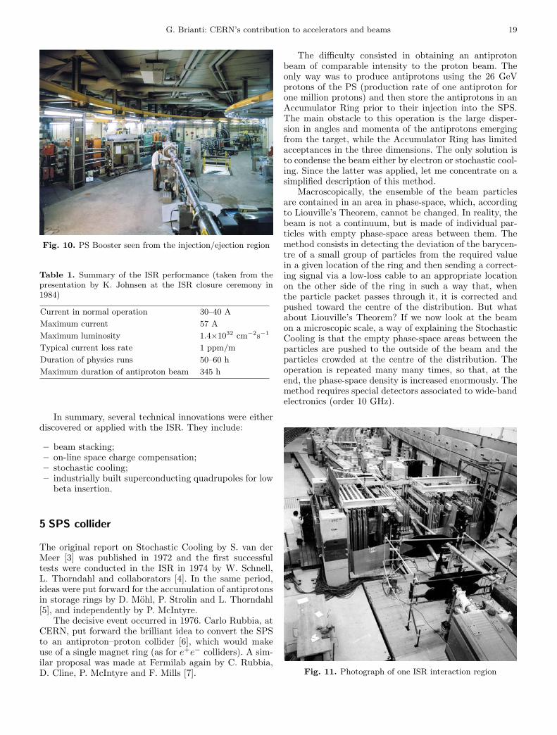
s−1. The very high currents were obtained by stacking inmomentum space, typically one thousand times the spaceoccupied by a single pulse from the PS. Figure 11 is aphotograph of a typical interaction region.
A considerable enhancement of accelerator technologywas due to the ISR, in particular concerning reliabilityand stability of all components, ultra-high vacuum (1000times lower pressure than in the PS), very intense beamsinducing space-charge effects and non-linear resonances.The know-how and expertise gained with the ISR were es-sential prerequisites for the success of the antiproton pro-gramme. The ISR performance is summarized in Table 1,as was once presented by the Project Leader, K. Johnsen.
DESIGN INTENSITY
1012
Pro
tons
per
Rin
g
Bea
m c
urre
nt w
ith 2
.4 s
ec r
epet
ition
(m
icro
amps
), 4
rin
gs
Energy Increasefrom 800 MeV to 1 GeV
Beam loading fast feedback
h = 10 cavitiesfor bunch flattening
(Qh, Qv) ~ (4.25, 5.60)Comp. 2nd order stopband
Comp. 3rd order stopband
Increase of acceptanceTransverse dampers
Long, in-phase damperNew Linac
Dampers for long. coupled bunch modes
(Qh, Qv) ~ (4.2, 5.3)
(Qh, Qv) ~ (4.25, 5.45)
Dynamic working point
"Skew" injection
Running - in(Qh, Qv) ~ (4.8, 4.8)
72 74 76 78 80 82 84 86 88 90
YEAR
1
2
3
1
2
3
4
5
6
7
8
9
10
11
Fig. 9. Evolution of Booster intensity over time
G. Brianti: CERN’s contribution to accelerators and beams 19
Fig. 10. PS Booster seen from the injection/ejection region
Table 1. Summary of the ISR performance (taken from thepresentation by K. Johnsen at the ISR closure ceremony in1984)
Current in normal operation 30–40 AMaximum current 57 AMaximum luminosity 1.4×1032 cm−2s−1
Typical current loss rate 1 ppm/mDuration of physics runs 50–60 hMaximum duration of antiproton beam 345 h
In summary, several technical innovations were eitherdiscovered or applied with the ISR. They include:
– beam stacking;– on-line space charge compensation;– stochastic cooling;– industrially built superconducting quadrupoles for low
beta insertion.
5 SPS collider
The original report on Stochastic Cooling by S. van derMeer [3] was published in 1972 and the first successfultests were conducted in the ISR in 1974 by W. Schnell,L. Thorndahl and collaborators [4]. In the same period,ideas were put forward for the accumulation of antiprotonsin storage rings by D. Mohl, P. Strolin and L. Thorndahl[5], and independently by P. McIntyre.
The decisive event occurred in 1976. Carlo Rubbia, atCERN, put forward the brilliant idea to convert the SPSto an antiproton–proton collider [6], which would makeuse of a single magnet ring (as for e+e− colliders). A sim-ilar proposal was made at Fermilab again by C. Rubbia,D. Cline, P. McIntyre and F. Mills [7].
The difficulty consisted in obtaining an antiprotonbeam of comparable intensity to the proton beam. Theonly way was to produce antiprotons using the 26 GeVprotons of the PS (production rate of one antiproton forone million protons) and then store the antiprotons in anAccumulator Ring prior to their injection into the SPS.The main obstacle to this operation is the large disper-sion in angles and momenta of the antiprotons emergingfrom the target, while the Accumulator Ring has limitedacceptances in the three dimensions. The only solution isto condense the beam either by electron or stochastic cool-ing. Since the latter was applied, let me concentrate on asimplified description of this method.
Macroscopically, the ensemble of the beam particlesare contained in an area in phase-space, which, accordingto Liouville’s Theorem, cannot be changed. In reality, thebeam is not a continuum, but is made of individual par-ticles with empty phase-space areas between them. Themethod consists in detecting the deviation of the barycen-tre of a small group of particles from the required valuein a given location of the ring and then sending a correct-ing signal via a low-loss cable to an appropriate locationon the other side of the ring in such a way that, whenthe particle packet passes through it, it is corrected andpushed toward the centre of the distribution. But whatabout Liouville’s Theorem? If we now look at the beamon a microscopic scale, a way of explaining the StochasticCooling is that the empty phase-space areas between theparticles are pushed to the outside of the beam and theparticles crowded at the centre of the distribution. Theoperation is repeated many many times, so that, at theend, the phase-space density is increased enormously. Themethod requires special detectors associated to wide-bandelectronics (order 10 GHz).
Fig. 11. Photograph of one ISR interaction region
20 G. Brianti: CERN’s contribution to accelerators and beams
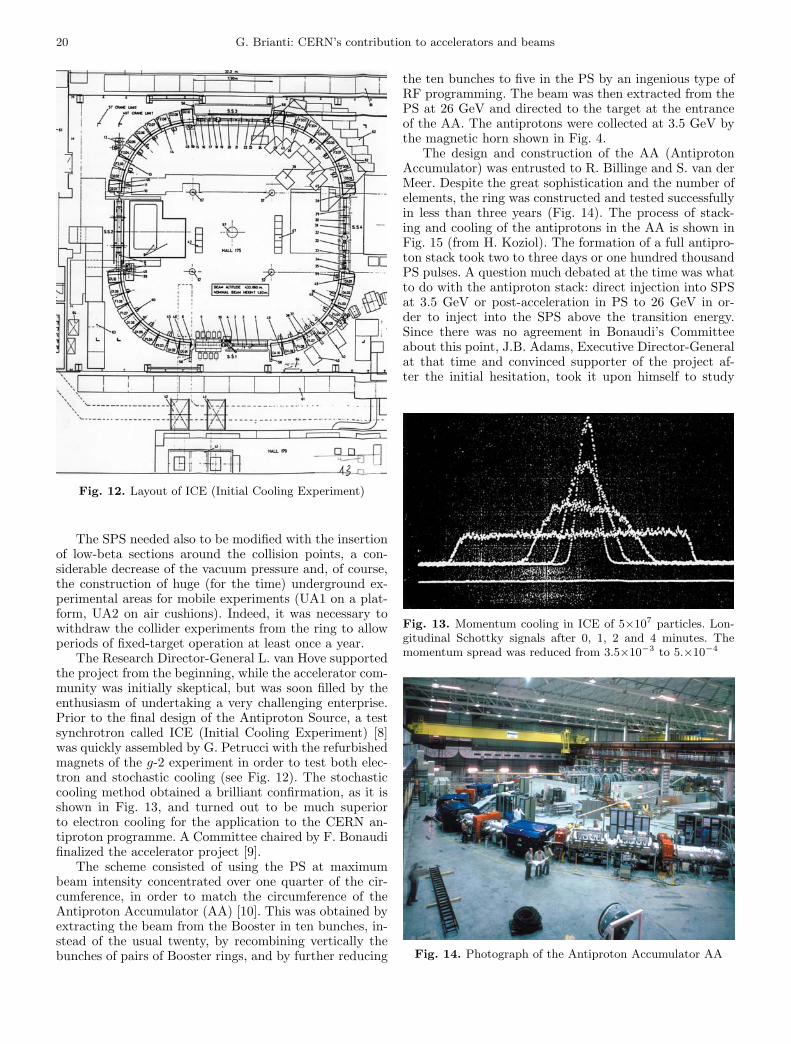
Fig. 12. Layout of ICE (Initial Cooling Experiment)
The SPS needed also to be modified with the insertionof low-beta sections around the collision points, a con-siderable decrease of the vacuum pressure and, of course,the construction of huge (for the time) underground ex-perimental areas for mobile experiments (UA1 on a plat-form, UA2 on air cushions). Indeed, it was necessary towithdraw the collider experiments from the ring to allowperiods of fixed-target operation at least once a year.
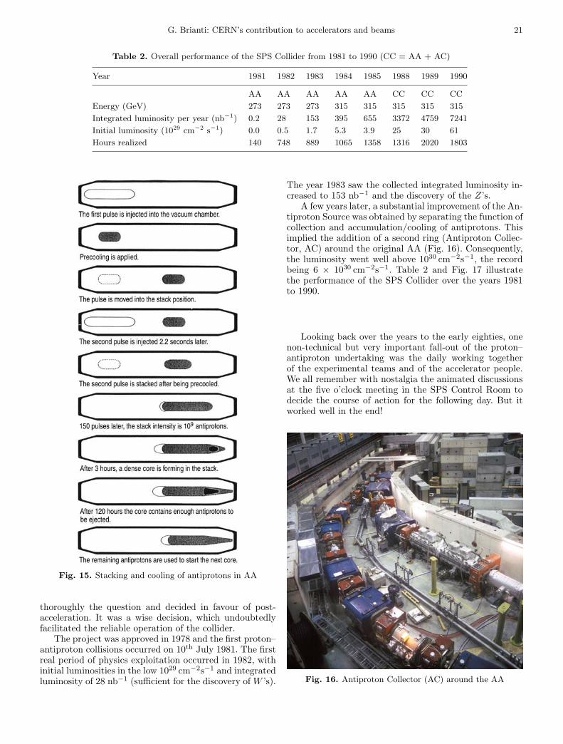
The Research Director-General L. van Hove supportedthe project from the beginning, while the accelerator com-munity was initially skeptical, but was soon filled by theenthusiasm of undertaking a very challenging enterprise.Prior to the final design of the Antiproton Source, a testsynchrotron called ICE (Initial Cooling Experiment) [8]was quickly assembled by G. Petrucci with the refurbishedmagnets of the g-2 experiment in order to test both elec-tron and stochastic cooling (see Fig. 12). The stochasticcooling method obtained a brilliant confirmation, as it isshown in Fig. 13, and turned out to be much superiorto electron cooling for the application to the CERN an-tiproton programme. A Committee chaired by F. Bonaudifinalized the accelerator project [9].
The scheme consisted of using the PS at maximumbeam intensity concentrated over one quarter of the cir-cumference, in order to match the circumference of theAntiproton Accumulator (AA) [10]. This was obtained byextracting the beam from the Booster in ten bunches, in-stead of the usual twenty, by recombining vertically thebunches of pairs of Booster rings, and by further reducing
the ten bunches to five in the PS by an ingenious type ofRF programming. The beam was then extracted from thePS at 26 GeV and directed to the target at the entranceof the AA. The antiprotons were collected at 3.5 GeV bythe magnetic horn shown in Fig. 4.
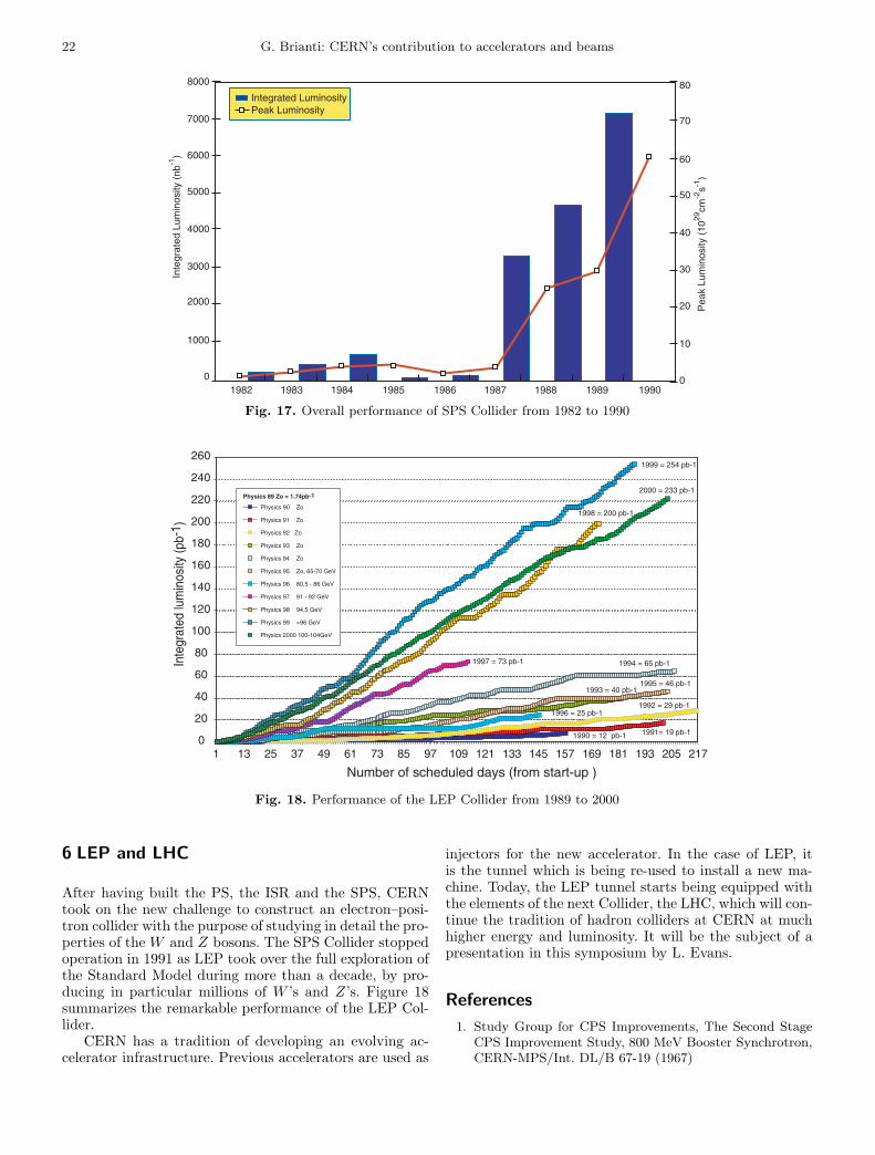
The design and construction of the AA (AntiprotonAccumulator) was entrusted to R. Billinge and S. van derMeer. Despite the great sophistication and the number ofelements, the ring was constructed and tested successfullyin less than three years (Fig. 14). The process of stack-ing and cooling of the antiprotons in the AA is shown inFig. 15 (from H. Koziol). The formation of a full antipro-ton stack took two to three days or one hundred thousandPS pulses. A question much debated at the time was whatto do with the antiproton stack: direct injection into SPSat 3.5 GeV or post-acceleration in PS to 26 GeV in or-der to inject into the SPS above the transition energy.Since there was no agreement in Bonaudi’s Committeeabout this point, J.B. Adams, Executive Director-Generalat that time and convinced supporter of the project af-ter the initial hesitation, took it upon himself to study
Fig. 13. Momentum cooling in ICE of 5×10⁷ particles. Lon-gitudinal Schottky signals after 0, 1, 2 and 4 minutes. Themomentum spread was reduced from 3.5×10⁻³ to 5.×10−4
Fig. 14. Photograph of the Antiproton Accumulator AA
G. Brianti: CERN’s contribution to accelerators and beams 21
Table 2. Overall performance of the SPS Collider from 1981 to 1990 (CC = AA + AC)
Year 1981 1982 1983 1984 1985 1988 1989 1990
AA AA AA AA AA CC CC CCEnergy (GeV) 273 273 273 315 315 315 315 315Integrated luminosity per year (nb−1) 0.2 28 153 395 655 3372 4759 7241Initial luminosity (1029 cm−2 s−1) 0.0 0.5 1.7 5.3 3.9 25 30 61Hours realized 140 748 889 1065 1358 1316 2020 1803
Fig. 15. Stacking and cooling of antiprotons in AA
thoroughly the question and decided in favour of post-acceleration. It was a wise decision, which undoubtedlyfacilitated the reliable operation of the collider.
The project was approved in 1978 and the first proton–antiproton collisions occurred on 10th July 1981. The firstreal period of physics exploitation occurred in 1982, withinitial luminosities in the low 1029 cm−2s−1 and integratedluminosity of 28 nb−1 (sufficient for the discovery of W ’s).
The year 1983 saw the collected integrated luminosity in-creased to 153 nb−1 and the discovery of the Z’s.
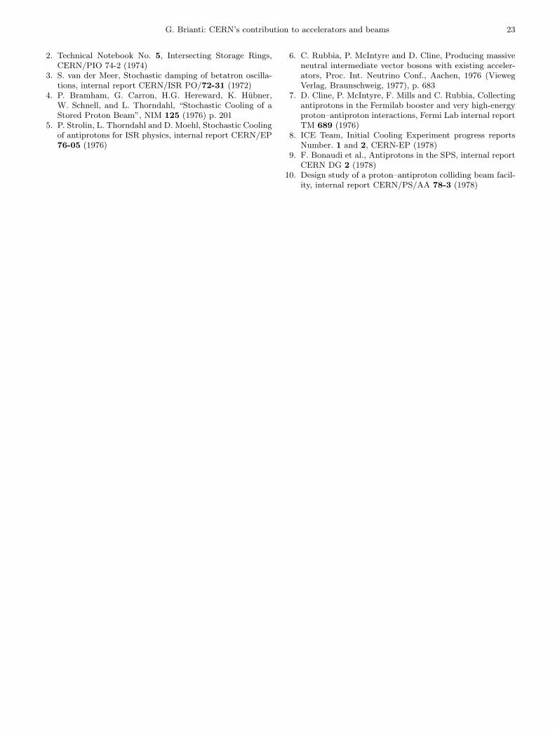
A few years later, a substantial improvement of the An-tiproton Source was obtained by separating the function ofcollection and accumulation/cooling of antiprotons. Thisimplied the addition of a second ring (Antiproton Collec-tor, AC) around the original AA (Fig. 16). Consequently,the luminosity went well above 1030 cm−2s−1, the recordbeing 6 × 1030 cm−2s−1. Table 2 and Fig. 17 illustratethe performance of the SPS Collider over the years 1981to 1990.
Looking back over the years to the early eighties, onenon-technical but very important fall-out of the proton–antiproton undertaking was the daily working togetherof the experimental teams and of the accelerator people.We all remember with nostalgia the animated discussionsat the five o’clock meeting in the SPS Control Room todecide the course of action for the following day. But itworked well in the end!
Fig. 16. Antiproton Collector (AC) around the AA
22 G. Brianti: CERN’s contribution to accelerators and beams
1982 1983 1984 1985 1986 1987 1988 1989 1990
8000
7000
6000
5000
4000
3000
2000
1000
0
80
70
60
50
40
30
20
10
0
Inte
grat
ed L
umin
osity
(nb
-1)
Pea
k Lu
min
osity
(10
29cm
-2s-1
)
Integrated LuminosityPeak Luminosity
Fig. 17. Overall performance of SPS Collider from 1982 to 1990
0
20
40
60
80
100
120
140
160
180
200
220
240
260
1 13 25 37 49 61 73 85 97 109 121 133 145 157 169 181 193 205 217
Number of scheduled days (from start-up )
Physics 90 Zo
Physics 91 Zo
Physics 92 Zo
Physics 93 Zo
Physics 94 Zo
Physics 95 Zo, 65-70 GeV
Physics 96 80.5 - 86 GeV
Physics 97 91 - 92 GeV
Physics 98 94.5 GeV
Physics 99 >96 GeV
Physics 2000 100-104GeV
Physics 89 Zo = 1.74pb-1
1999 = 254 pb-1
1998 = 200 pb-1
2000 = 233 pb-1
1997 = 73 pb-1 1994 = 65 pb-1
1995 = 46 pb-1
1996 = 25 pb-1
1993 = 40 pb-1
1991= 19 pb-1
1992 = 29 pb-1
1990 = 12 pb-1
Inte
grat
ed lu
min
osity
(pb-
1 )
Fig. 18. Performance of the LEP Collider from 1989 to 2000
6 LEP and LHC
After having built the PS, the ISR and the SPS, CERNtook on the new challenge to construct an electron–posi-tron collider with the purpose of studying in detail the pro-perties of the W and Z bosons. The SPS Collider stoppedoperation in 1991 as LEP took over the full exploration ofthe Standard Model during more than a decade, by pro-ducing in particular millions of W ’s and Z’s. Figure 18summarizes the remarkable performance of the LEP Col-lider.
CERN has a tradition of developing an evolving ac-celerator infrastructure. Previous accelerators are used as
injectors for the new accelerator. In the case of LEP, itis the tunnel which is being re-used to install a new ma-chine. Today, the LEP tunnel starts being equipped withthe elements of the next Collider, the LHC, which will con-tinue the tradition of hadron colliders at CERN at muchhigher energy and luminosity. It will be the subject of apresentation in this symposium by L. Evans.
References1. Study Group for CPS Improvements, The Second Stage
CPS Improvement Study, 800 MeV Booster Synchrotron,CERN-MPS/Int. DL/B 67-19 (1967)
G. Brianti: CERN’s contribution to accelerators and beams 23
2. Technical Notebook No. 5, Intersecting Storage Rings,CERN/PIO 74-2 (1974)
3. S. van der Meer, Stochastic damping of betatron oscilla-tions, internal report CERN/ISR PO/72-31 (1972)
4. P. Bramham, G. Carron, H.G. Hereward, K. Hubner,W. Schnell, and L. Thorndahl, “Stochastic Cooling of aStored Proton Beam”, NIM 125 (1976) p. 201
5. P. Strolin, L. Thorndahl and D. Moehl, Stochastic Coolingof antiprotons for ISR physics, internal report CERN/EP76-05 (1976)
6. C. Rubbia, P. McIntyre and D. Cline, Producing massiveneutral intermediate vector bosons with existing acceler-ators, Proc. Int. Neutrino Conf., Aachen, 1976 (ViewegVerlag, Braunschweig, 1977), p. 683
7. D. Cline, P. McIntyre, F. Mills and C. Rubbia, Collectingantiprotons in the Fermilab booster and very high-energyproton–antiproton interactions, Fermi Lab internal reportTM 689 (1976)
8. ICE Team, Initial Cooling Experiment progress reportsNumber. 1 and 2, CERN-EP (1978)
9. F. Bonaudi et al., Antiprotons in the SPS, internal reportCERN DG 2 (1978)
10. Design study of a proton–antiproton colliding beam facil-ity, internal report CERN/PS/AA 78-3 (1978)