Embed Size (px)
Citation preview
CERN SAFETY REVIEW
MERIT (n-ToF-11) 15T Pulsed Magnet for Mercury Target Development
Neutrino Factory and Muon Collider Collaboration Peter H. Titus
MIT Plasma Science and Fusion Center (617) 253 1344, [email protected], http://www.psfc.mit.edu/people/titus
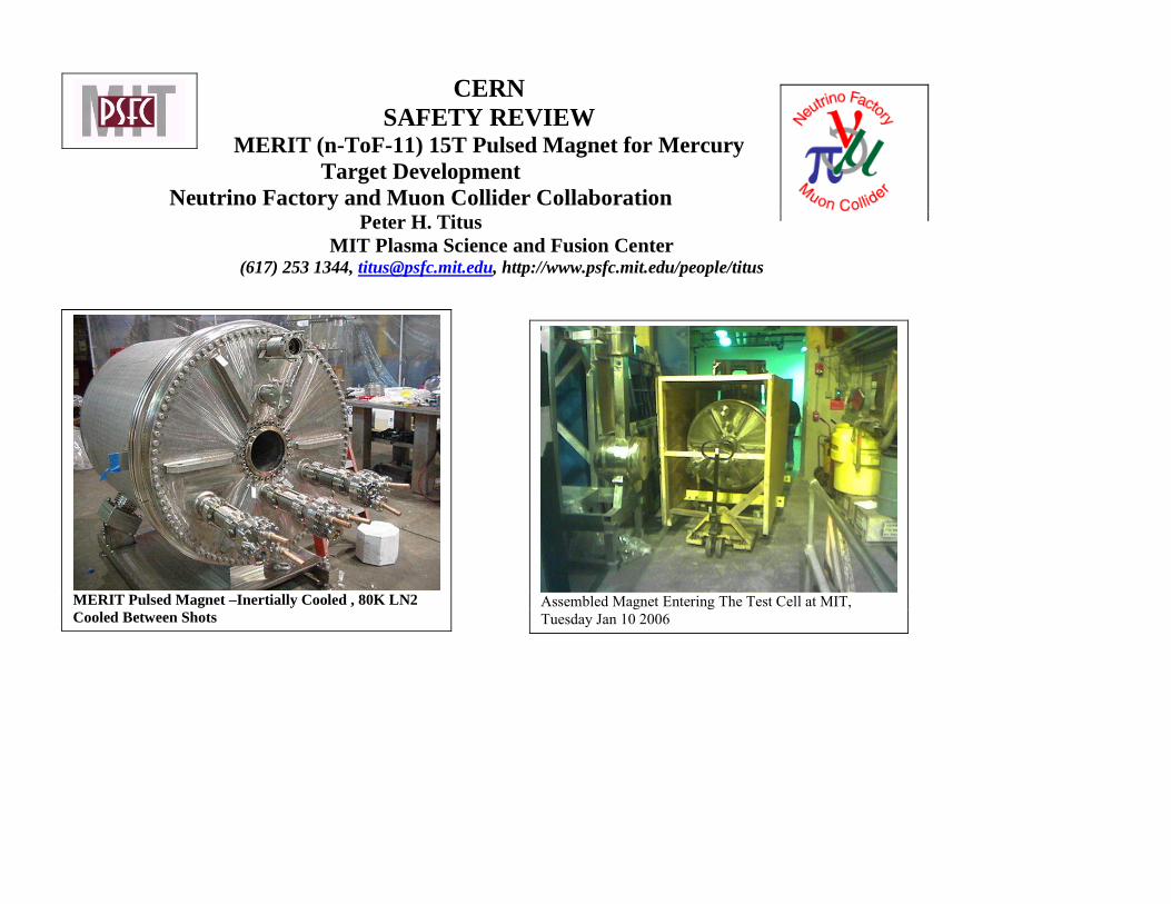
MERIT Pulsed Magnet –Inertially Cooled , 80K LN2 Cooled Between Shots
Assembled Magnet Entering The Test Cell at MIT, Tuesday Jan 10 2006
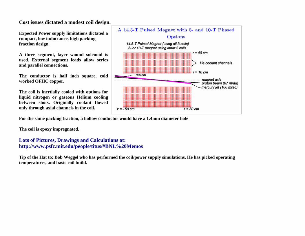
Cost issues dictated a modest coil design. Expected Power supply limitations dictated a compact, low inductance, high packing fraction design. A three segment, layer wound solenoid is used. External segment leads allow series and parallel connections. The conductor is half inch square, cold worked OFHC copper. The coil is inertially cooled with options for liquid nitrogen or gaseous Helium cooling between shots. Originally coolant flowed only through axial channels in the coil. For the same packing fraction, a hollow conductor would have a 1.4mm diameter hole The coil is epoxy impregnated. Lots of Pictures, Drawings and Calculations at: http://www.psfc.mit.edu/people/titus/#BNL%20Memos Tip of the Hat to: Bob Weggel who has performed the coil/power supply simulations. He has picked operating temperatures, and basic coil build.
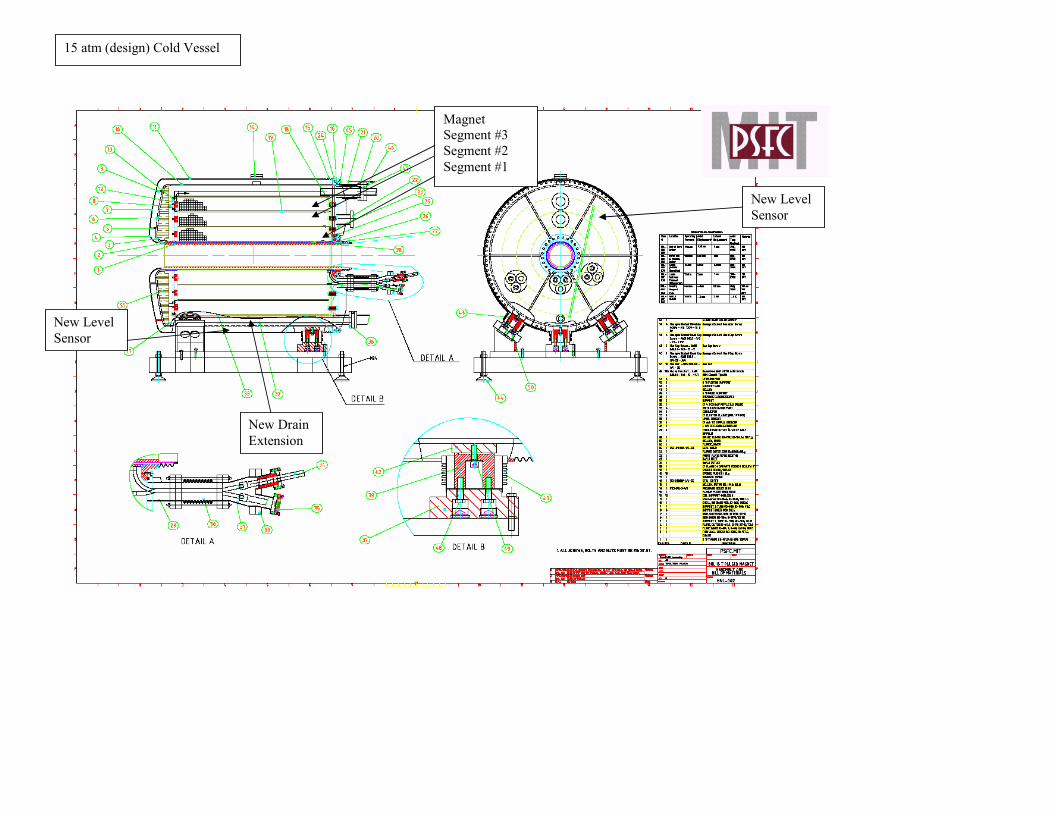
New Level Sensor
New Level Sensor
New Drain Extension
Magnet Segment #3 Segment #2 Segment #1
15 atm (design) Cold Vessel
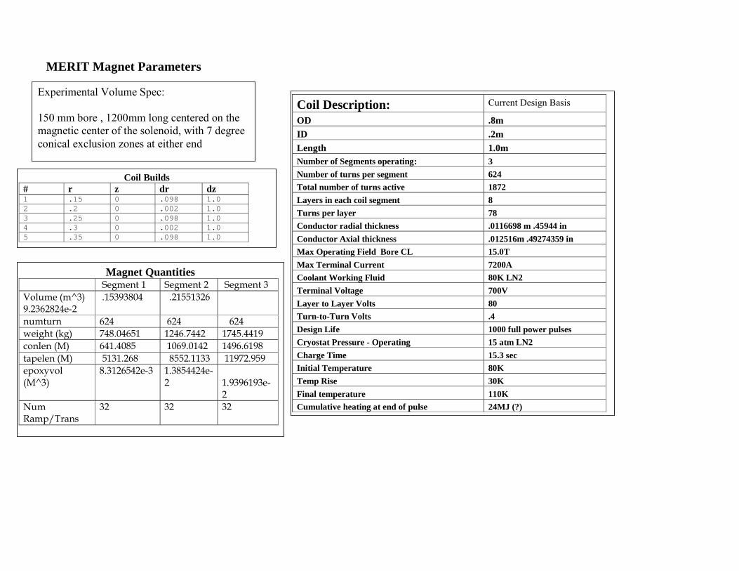
MERIT Magnet Parameters
Coil Builds # r z dr dz 1 .15 0 .098 1.0 2 .2 0 .002 1.0 3 .25 0 .098 1.0 4 .3 0 .002 1.0 5 .35 0 .098 1.0
Coil Description: Current Design Basis
OD .8m ID .2m Length 1.0m Number of Segments operating: 3 Number of turns per segment 624 Total number of turns active 1872 Layers in each coil segment 8 Turns per layer 78 Conductor radial thickness .0116698 m .45944 in Conductor Axial thickness .012516m .49274359 in Max Operating Field Bore CL 15.0T Max Terminal Current 7200A Coolant Working Fluid 80K LN2 Terminal Voltage 700V Layer to Layer Volts 80 Turn-to-Turn Volts .4 Design Life 1000 full power pulses Cryostat Pressure - Operating 15 atm LN2 Charge Time 15.3 sec Initial Temperature 80K Temp Rise 30K Final temperature 110K Cumulative heating at end of pulse 24MJ (?)
Magnet Quantities Segment 1 Segment 2 Segment 3 Volume (m^3) 9.2362824e-2
.15393804 .21551326
numturn 624 624 624 weight (kg) 748.04651 1246.7442 1745.4419 conlen (M) 641.4085 1069.0142 1496.6198 tapelen (M) 5131.268 8552.1133 11972.959 epoxyvol (M^3)
8.3126542e-3 1.3854424e-2
1.9396193e-2
Num Ramp/Trans
32 32 32
Experimental Volume Spec: 150 mm bore , 1200mm long centered on the magnetic center of the solenoid, with 7 degree conical exclusion zones at either end
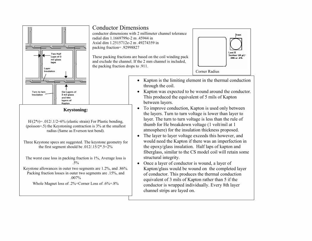
Conductor Dimensions conductor dimensions with 2 millimeter channel tolerance radial dim 1.1669799e-2 m .45944 in Axial dim 1.2515712e-2 m .49274359 in packing fraction= .92998827 These packing fractions are based on the coil winding pack and exclude the channel. If the 2 mm channel is included, the packing fraction drops to .911.
Corner Radius
• Kapton is the limiting element in the thermal conduction through the coil.
• Kapton was expected to be wound around the conductor. This produced the equivalent of 5 mils of Kapton between layers.
• To improve conduction, Kapton is used only between the layers. Turn to turn voltage is lower than layer to layer. The turn to turn voltage is less than the rule of thumb for He breakdown voltage (1 volt/mil at 1 atmosphere) for the insulation thickness proposed.
• The layer to layer voltage exceeds this however, and would need the Kapton if there was an imperfection in the epoxy/glass insulation. Half laps of kapton and fiberglass, similar to the CS model coil will retain some structural integrity.
• Once a layer of conductor is wound, a layer of Kapton/glass would be wound on the completed layer of conductor. This produces the thermal conduction equivalent of 3 mils of Kapton rather than 5 if the conductor is wrapped individually. Every 8th layer channel strips are layed on.
Keystoning:
H/(2*r)= .012/.1/2=6% (elastic strain) For Plastic bending, (poisson=.5) the Keystoning contraction is 3% at the smallest
radius (Same as Everson test bend). Three Keystone specs are suggested. The keystone geometry for
the first segment should be .012/.15/2*.5=2%
The worst case loss in packing fraction is 1%, Average loss is .5%
Keystone allowances in outer two segments are 1.2%, and .86%. Packing fraction losses in outer two segments are .15%, and
.007% Whole Magnet loss of .2%+Corner Loss of .6%=.8%
Safety Review Status: • The Magnet and Vessel Design have had Peer
Engineering Review by BNL, MIT(P.Stahl) and by George Mulhulland.
• The Magnet System has been reviewed by BNL(Peter Wanderer’ Group) and MIT-PSFC Safety Review Committees.
• The MERIT pulsed magnet design builds off of copper magnet experience in fusion research at MIT (Alcator C-Mod).
• The Magnet has been electrically tested by Everson-Tesla and the Vessels have been pressure tested by CVIP and the system will go through Pre-operational tests at MIT-PSFC
Plasma Science and Fusion Center
Office of Environment, Safety, and Health 190 Albany Street, NW21 2nd floor
617-253-8440 (Catherine Fiore, head) 617-253-8917 (Matt Fulton, Facilities Manager) 617-258-5473 (Nancy Masley, administrator) 617-253-5982 (Bill Byford, assistant safety officer) Fax 617-252-1808
Some of the Postulated of Safety Issues: Magnetic Field Hazard 6m to the 5 gauss line Feromagnetic Material Projectiles Joint Failure Excessive motion Omission of a Force Component Insulation Failure, Arcing Leaks Oxygen Deficiency Hazards He/LN2 Cryostat Leak Mechanical Seal Failure Bellows Crack Ceramaseal Break Lead Gland Nut Leak Over Pressure Hotter than expected Magnet Loss of Vacuum in Jacket Vacuum Jacket Volume Pressurization Quick charge of LN2 with warm cryostat Failure of Bore Heater Thermal Shock Quick charge of LN2 with warm cryostat – The inner magnet segments were thermally shocked at Everson-Tesla Accident Fire - Avoid Flammable Materials Seismic
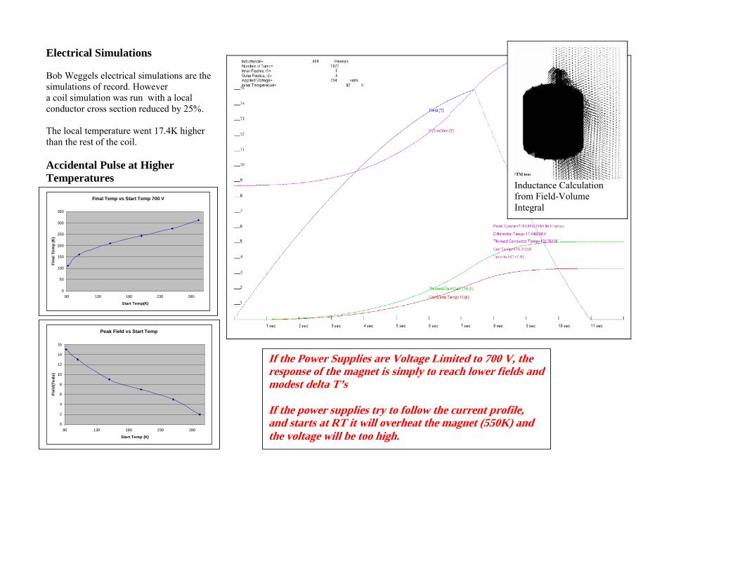
Electrical Simulations Bob Weggels electrical simulations are the simulations of record. However a coil simulation was run with a local conductor cross section reduced by 25%. The local temperature went 17.4K higher than the rest of the coil. Accidental Pulse at Higher Temperatures
Inductance Calculation from Field-Volume Integral
Final Temp vs Start Temp 700 V
0
50
100
150
200
250
300
350
80 130 180 230 280
Start Temp(K)
Fina
l Tem
p (K
)
Peak Field vs Start Temp
0
2
4
6
8
10
12
14
16
80 130 180 230 280
Start Temp (K)
Fiel
d(Te
sla)
If the Power Supplies are Voltage Limited to 700 V, the response of the magnet is simply to reach lower fields and modest delta T’s If the power supplies try to follow the current profile, and starts at RT it will overheat the magnet (550K) and the voltage will be too high.
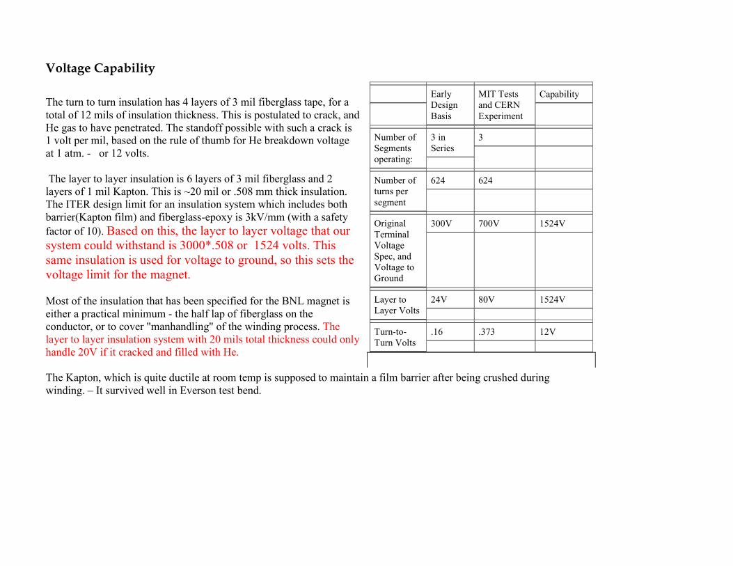
Voltage Capability
The turn to turn insulation has 4 layers of 3 mil fiberglass tape, for a total of 12 mils of insulation thickness. This is postulated to crack, and He gas to have penetrated. The standoff possible with such a crack is 1 volt per mil, based on the rule of thumb for He breakdown voltage at 1 atm. - or 12 volts. The layer to layer insulation is 6 layers of 3 mil fiberglass and 2 layers of 1 mil Kapton. This is ~20 mil or .508 mm thick insulation. The ITER design limit for an insulation system which includes both barrier(Kapton film) and fiberglass-epoxy is 3kV/mm (with a safety factor of 10). Based on this, the layer to layer voltage that our system could withstand is 3000*.508 or 1524 volts. This same insulation is used for voltage to ground, so this sets the voltage limit for the magnet. Most of the insulation that has been specified for the BNL magnet is either a practical minimum - the half lap of fiberglass on the conductor, or to cover "manhandling" of the winding process. The layer to layer insulation system with 20 mils total thickness could only handle 20V if it cracked and filled with He. The Kapton, which is quite ductile at room temp is supposed to maintain a film barrier after being crushed during winding. – It survived well in Everson test bend.
Early Design Basis
MIT Tests and CERN Experiment
Capability
Number of Segments operating:
3 in Series
3
Number of turns per segment
624 624
Original Terminal Voltage Spec, and Voltage to Ground
300V 700V 1524V
Layer to Layer Volts
24V 80V 1524V
Turn-to-Turn Volts
.16 .373 12V
Specification Content relating to Insulation integrity:
Electrical Testing The Seller shall assign a trained personnel and provide all necessary test equipment including digital multimeters for resistance measurement and DC hipot testers for ground insulation testing, during assembly process and at the completion of the prototype cryostat. Electrical testing of the electrical connection and component, including pulsed coil and bus connection, sensors, and diagnostic wiring, shall be performed after a component becomes inaccessible for service unless the enclosure is disassembled. The checkpoints and the type of electrical testing during assembly stage shall be defined by Seller in the fabrication plan and approved by the Purchaser’s Representative.
Insulation test No measurable electrical connection at mega-Ohm range shall be allowed between the ground and any diagnostic component / connection, between different sensors, and between sensor and the coil circuit.
DC Hipot Testing The initial DC hipot testing shall be performed on the pulsed magnet coils and lead connections before they are installed. All subsequently measured leakage currents shall be compared with the initial value for verification. The coils and lead connections shall be tested at 1 kV for 1 minute with the limiting current of a DC hipot tester set to 10 micro Amp. The allowable leakage current shall be no more than 5 micro Amp. Caution:
• Do not perform hipot testing with the coil / lead in evacuated enclosure. • Isolate the voltage tap wires when the coil / lead is tested with hipot tester.
Do not use hipot tester on any sensor.
Structural and Geometric Design Criteria Magnet: Fusion project criteria are used for guidance in coil design ITER and FIRE design documents allow the primary membrane stress to be based on the lesser of 2/3 of the Yield Strength (Sy) or ½ of the Ultimate Strength (Su). The ASME Code bases the primary stress on 1/3 ultimate. The fusion project based criteria is based on a distinction between coils that are supported by cases and those that are not. For structural elements ASME -like criteria are adopted with membrane stresses remaining below the maximum allowable stress, Sm, where Sm is the lesser of 2/3*yield or 1/3 ultimate. Bending discontinuity, and secondary stresses are treated in a manner similar to the ASME Code. Bolting, Support Structures: Guidance for bolting and column buckling is taken from AISC, with average net section bolt stresses kept below 0.6*yield. Yield Strength and Tensile Strength properties are taken at the loaded temperature. Vessels: The cryostat and vacuum jackets are to be qualified and manufactured in accordance with ASMEVIII. However the vessels are not stamped. Seismic The magnet is to be seismically qualified in accordance with the (Uniform Building Code? - .1g horizontal).
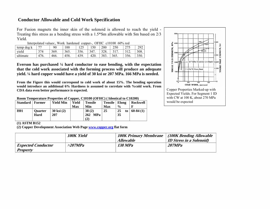
Conductor Allowable and Cold Work Specification For Fusion magnets the inner skin of the solenoid is allowed to reach the yield - Treating this stress as a bending stress with a 1.5*Sm allowable with Sm based on 2/3 Yield.
Interpolated values:, Work hardened copper-, OFHC c10100 60% red temp deg k 77 90 100 125 150 200 250 275 292yield 374 369. 365. 356. 347. 328. 317. 312. 308.ultimate 476. 466. 458. 439. 420. 383. 365. 356. 350. Everson has purchased ¼ hard conductor to ease bending, with the expectation that the cold work associated with the forming process will produce an adequate yield. ¼ hard copper would have a yield of 30 ksi or 207 MPa. 166 MPa is needed. From the Figure this would correspond to cold work of about 15%. The bending operation would introduce an additional 6% Hardness is assumed to correlate with %cold work. From CDA data even better performance is expected. Room Temperature Properties of Copper, C10100 (OFHC) ( Identical to C10200) Standard Former Yield Min Yield
Max Tensile Min
Tensile Max
Elong %
Rockwell F
H01 Quarter Hard
30 ksi (2) 207
38 (2) 262 MPa (2)
25 25 to 35
60-84 (1)
(1) ASTM B152 (2) Copper Development Association Web Page www.copper.org flat form 100K Yield 100K Primary Membrane
Allowable (100K Bending Allowable ID Stress in a Solenoid)
Expected Conductor Property
>207MPa 138 MPa 207MPa
Copper Properties Marked-up with Expected Yields. For Segment 1 ID with CW at 100 K, about 270 MPa would be expected
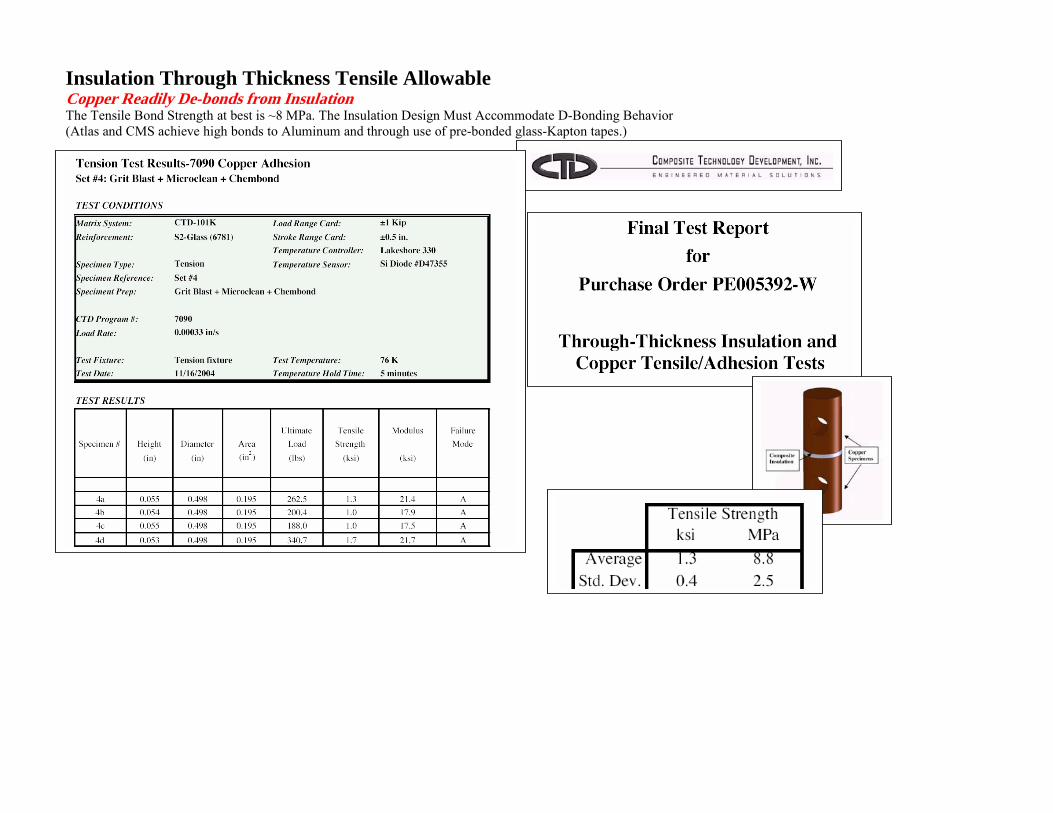
Insulation Through Thickness Tensile Allowable Copper Readily De-bonds from Insulation The Tensile Bond Strength at best is ~8 MPa. The Insulation Design Must Accommodate D-Bonding Behavior (Atlas and CMS achieve high bonds to Aluminum and through use of pre-bonded glass-Kapton tapes.)
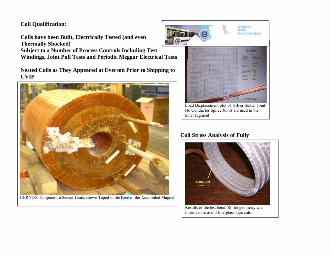
Coil Qualification: Coils have been Built, Electrically Tested (and even Thermally Shocked) Subject to a Number of Process Controls Including Test Windings, Joint Pull Tests and Periodic Meggar Electrical Tests Nested Coils as They Appeared at Everson Prior to Shipping to CVIP
Coil Stress Analysis of Fully
Load Displacement plot of Silver Solder Joint. No Conductor Splice Joints are used in the inner segment
Results of the test bend. Roller geometry was improved to avoid fiberglass tape cuts.
CERNOX Temperature Sensor Leads shown Taped to the Face of the Assembled Magnet
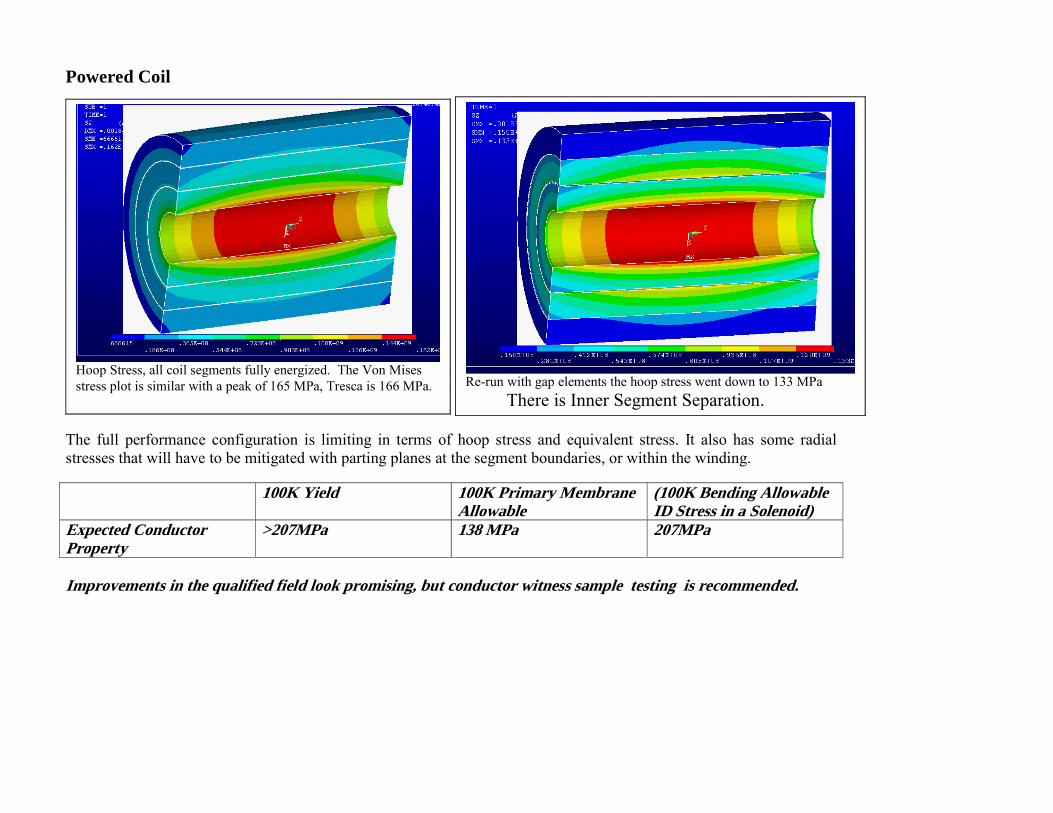
Powered Coil
The full performance configuration is limiting in terms of hoop stress and equivalent stress. It also has some radial stresses that will have to be mitigated with parting planes at the segment boundaries, or within the winding. 100K Yield 100K Primary Membrane
Allowable (100K Bending Allowable ID Stress in a Solenoid)
Expected Conductor Property
>207MPa 138 MPa 207MPa
Improvements in the qualified field look promising, but conductor witness sample testing is recommended.
Hoop Stress, all coil segments fully energized. The Von Mises stress plot is similar with a peak of 165 MPa, Tresca is 166 MPa.
Re-run with gap elements the hoop stress went down to 133 MPa
There is Inner Segment Separation.
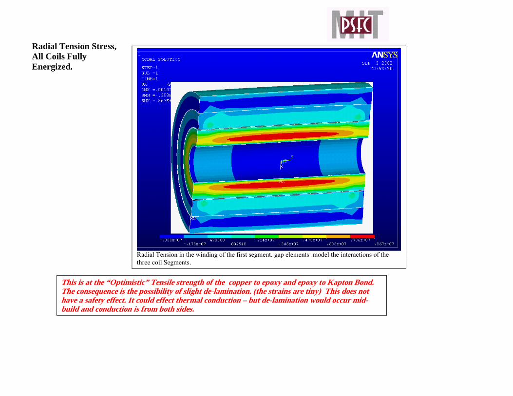
Radial Tension Stress, All Coils Fully Energized.
Radial Tension in the winding of the first segment. gap elements model the interactions of the three coil Segments.
This is at the “Optimistic” Tensile strength of the copper to epoxy and epoxy to Kapton Bond. The consequence is the possibility of slight de-lamination. (the strains are tiny) This does not have a safety effect. It could effect thermal conduction – but de-lamination would occur mid-build and conduction is from both sides.
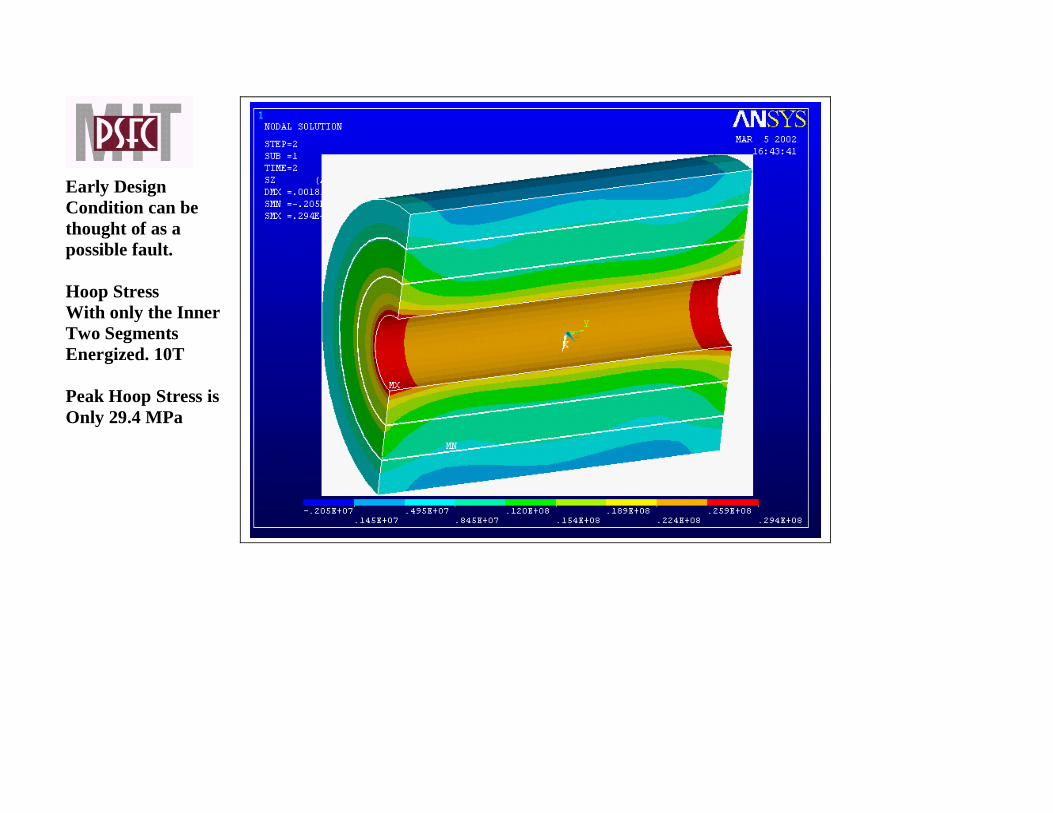
Early Design Condition can be thought of as a possible fault. Hoop Stress With only the Inner Two Segments Energized. 10T Peak Hoop Stress is Only 29.4 MPa
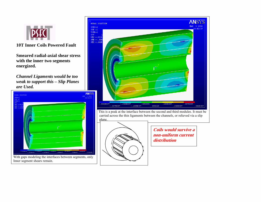
10T Inner Coils Powered Fault Smeared radial-axial shear stress with the inner two segments energized. Channel Ligaments would be too weak to support this – Slip Planes are Used.
This is a peak at the interface between the second and third modules. It must be carried across the thin ligaments between the channels, or relieved via a slip plane.
With gaps modeling the interfaces between segments, only Inner segment shears remain.
Coils would survive a non-uniform current distribution
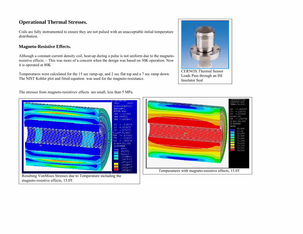
Operational Thermal Stresses. Coils are fully instrumented to ensure they are not pulsed with an unacceptable initial temperature distribution. Magneto-Resistive Effects. Although a constant current density coil, heat-up during a pulse is not uniform due to the magneto-resistive effects. – This was more of a concern when the design was based on 30K operation. Now it is operated at 80K Temperatures were calculated for the 15 sec ramp-up, and 2 sec flat top and a 7 sec ramp down. The NIST Kohler plot and fitted equation was used for the magneto-resistance. The stresses from magneto-resistivev effects are small, less than 5 MPa.
CERNOX Thermal Sensor Leads Pass through an ISI Insulator Seal
Resulting VonMises Stresses due to Temperature including the magneto-resistive effects, 15.0T.
Temperatures with magneto-resistive effects, 15.0T
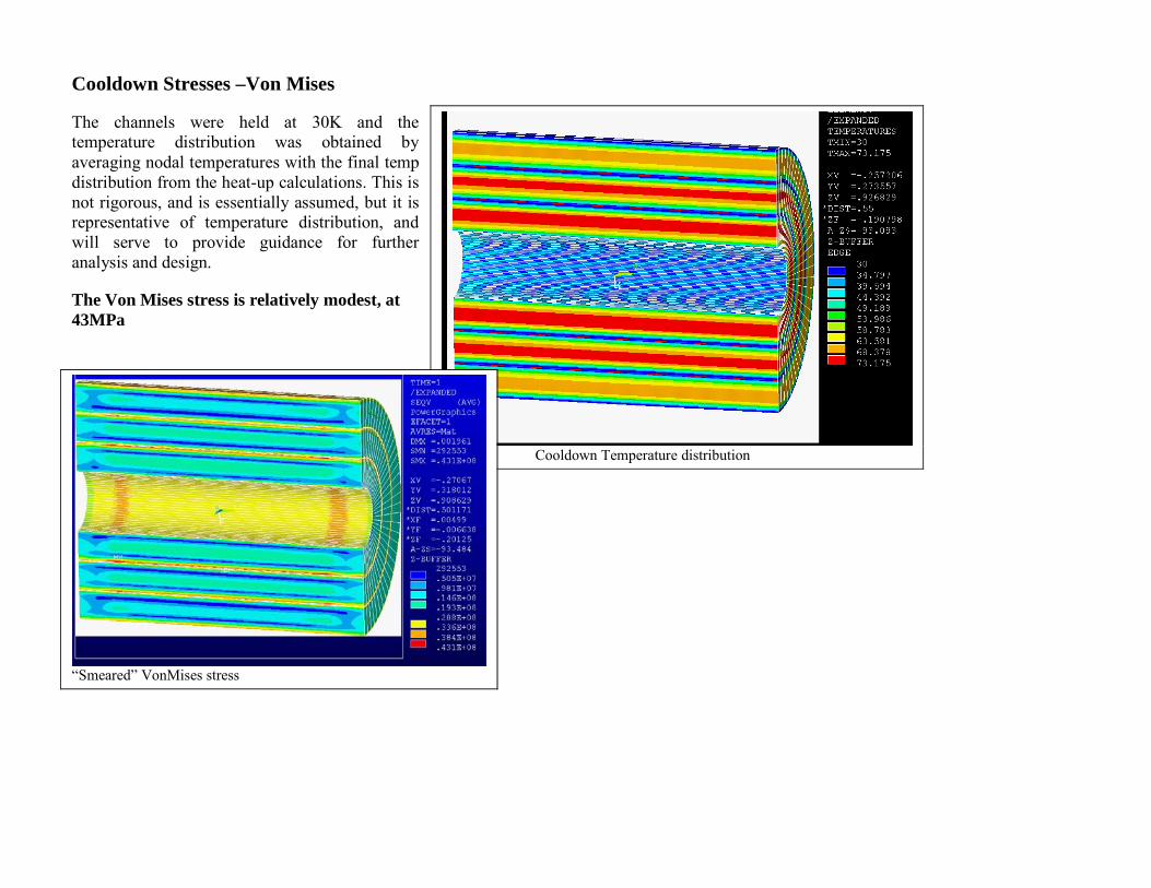
Cooldown Stresses –Von Mises The channels were held at 30K and the temperature distribution was obtained by averaging nodal temperatures with the final temp distribution from the heat-up calculations. This is not rigorous, and is essentially assumed, but it is representative of temperature distribution, and will serve to provide guidance for further analysis and design. The Von Mises stress is relatively modest, at 43MPa
Cooldown Temperature distribution
“Smeared” VonMises stress
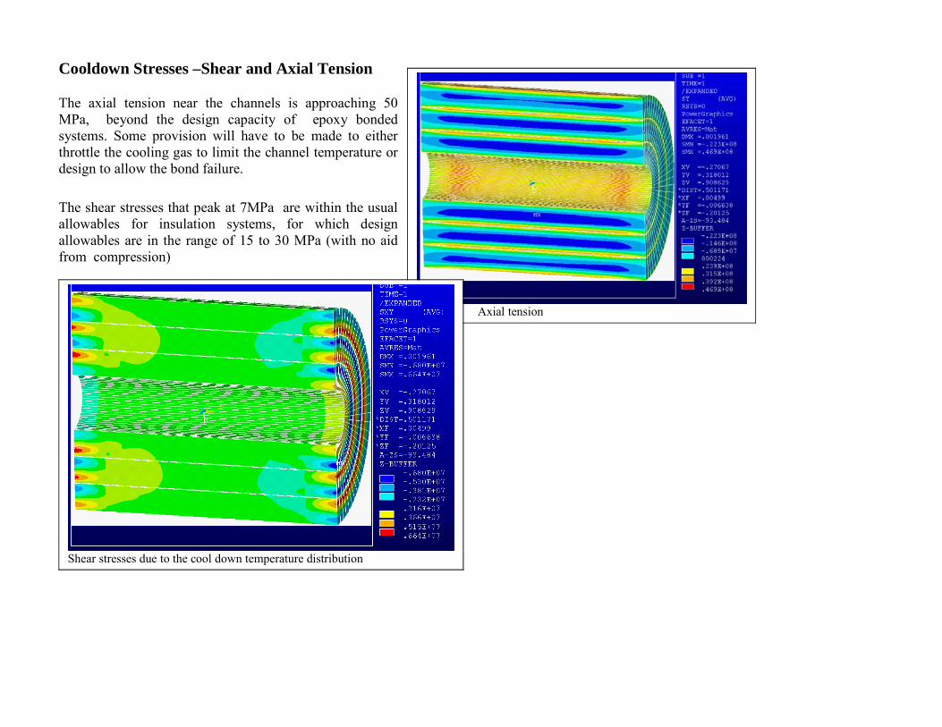
Cooldown Stresses –Shear and Axial Tension The axial tension near the channels is approaching 50 MPa, beyond the design capacity of epoxy bonded systems. Some provision will have to be made to either throttle the cooling gas to limit the channel temperature or design to allow the bond failure. The shear stresses that peak at 7MPa are within the usual allowables for insulation systems, for which design allowables are in the range of 15 to 30 MPa (with no aid from compression)
Axial tension
Shear stresses due to the cool down temperature distribution
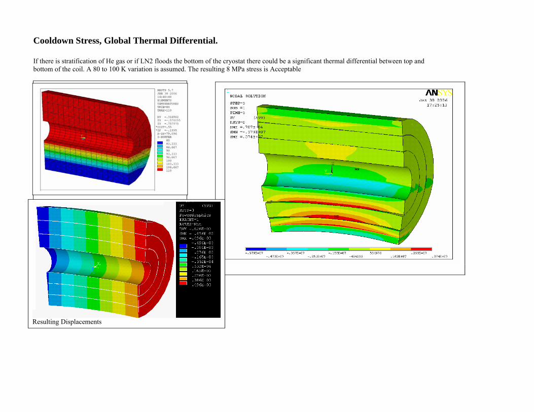
Cooldown Stress, Global Thermal Differential. If there is stratification of He gas or if LN2 floods the bottom of the cryostat there could be a significant thermal differential between top and bottom of the coil. A 80 to 100 K variation is assumed. The resulting 8 MPa stress is Acceptable
Assumed temperature variation
Resulting Displacements
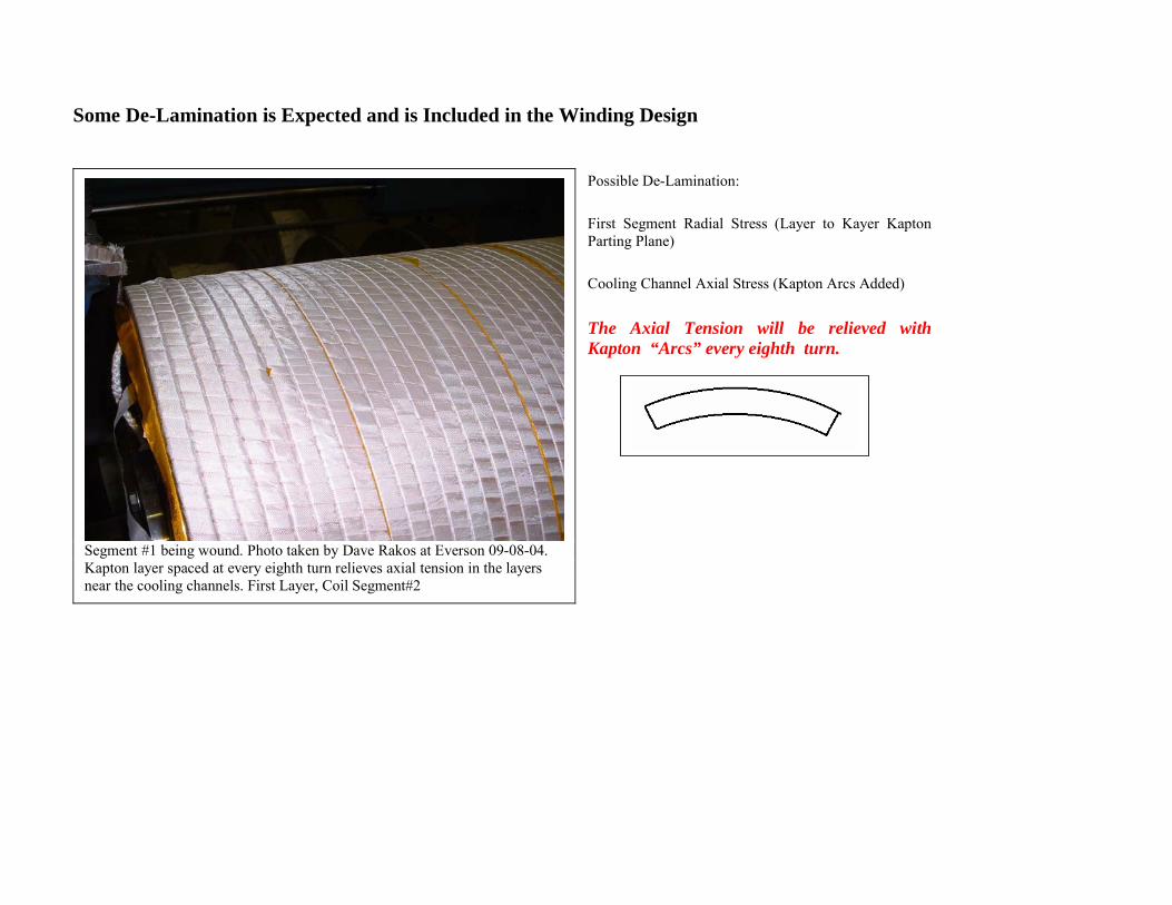
Some De-Lamination is Expected and is Included in the Winding Design
Possible De-Lamination: First Segment Radial Stress (Layer to Kayer Kapton Parting Plane) Cooling Channel Axial Stress (Kapton Arcs Added) The Axial Tension will be relieved with Kapton “Arcs” every eighth turn.
Segment #1 being wound. Photo taken by Dave Rakos at Everson 09-08-04. Kapton layer spaced at every eighth turn relieves axial tension in the layers near the cooling channels. First Layer, Coil Segment#2
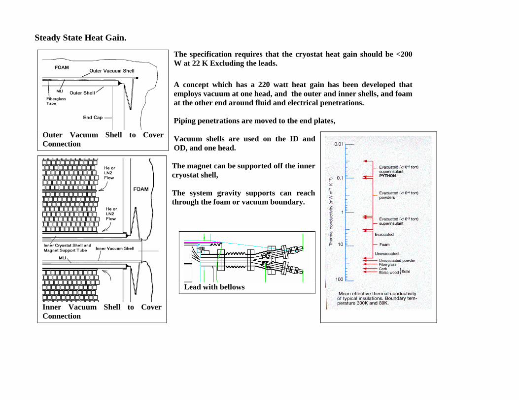
Steady State Heat Gain.
The specification requires that the cryostat heat gain should be <200 W at 22 K Excluding the leads. A concept which has a 220 watt heat gain has been developed that employs vacuum at one head, and the outer and inner shells, and foam at the other end around fluid and electrical penetrations. Piping penetrations are moved to the end plates, Vacuum shells are used on the ID and OD, and one head. The magnet can be supported off the inner cryostat shell, The system gravity supports can reach through the foam or vacuum boundary.
Outer Vacuum Shell to Cover Connection
Inner Vacuum Shell to Cover Connection
Lead with bellows
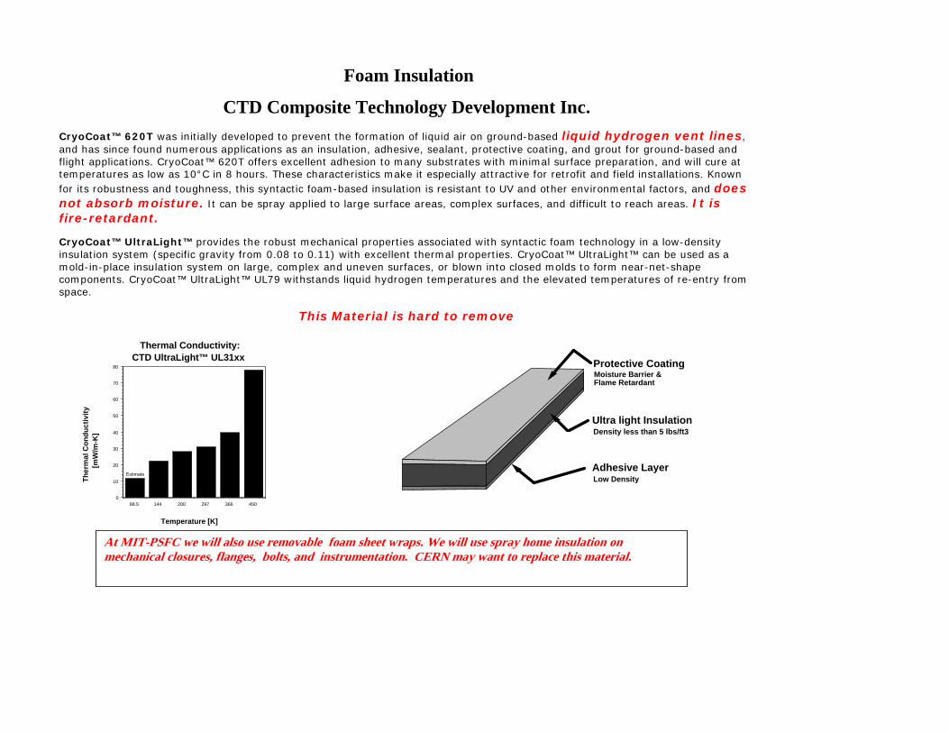
Foam Insulation
CTD Composite Technology Development Inc. CryoCoat™ 620T was initially developed to prevent the formation of liquid air on ground-based liquid hydrogen vent lines, and has since found numerous applications as an insulation, adhesive, sealant, protective coating, and grout for ground-based and flight applications. CryoCoat™ 620T offers excellent adhesion to many substrates with minimal surface preparation, and will cure at temperatures as low as 10°C in 8 hours. These characteristics make it especially attractive for retrofit and field installations. Known for its robustness and toughness, this syntactic foam-based insulation is resistant to UV and other environmental factors, and does not absorb moisture. It can be spray applied to large surface areas, complex surfaces, and difficult to reach areas. It is fire-retardant.
CryoCoat™ UltraLight™ provides the robust mechanical properties associated with syntactic foam technology in a low-density insulation system (specific gravity from 0.08 to 0.11) with excellent thermal properties. CryoCoat™ UltraLight™ can be used as a mold-in-place insulation system on large, complex and uneven surfaces, or blown into closed molds to form near-net-shape components. CryoCoat™ UltraLight™ UL79 withstands liquid hydrogen temperatures and the elevated temperatures of re-entry from space.
This Material is hard to remove
88.5 144 200 297 366 4500
10
20
30
40
50
60
70
80
Thermal Conductivity: CTD UltraLight™ UL31xx
Temperature [K]
Ther
mal
Con
duct
ivity
[m
W/m
-K]
Estimate
Adhesive Layer
Ultra light Insulation
Protective CoatingMoisture Barrier & Flame Retardant
Density less than 5 lbs/ft3
Low Density
At MIT-PSFC we will also use removable foam sheet wraps. We will use spray home insulation on mechanical closures, flanges, bolts, and instrumentation. CERN may want to replace this material.
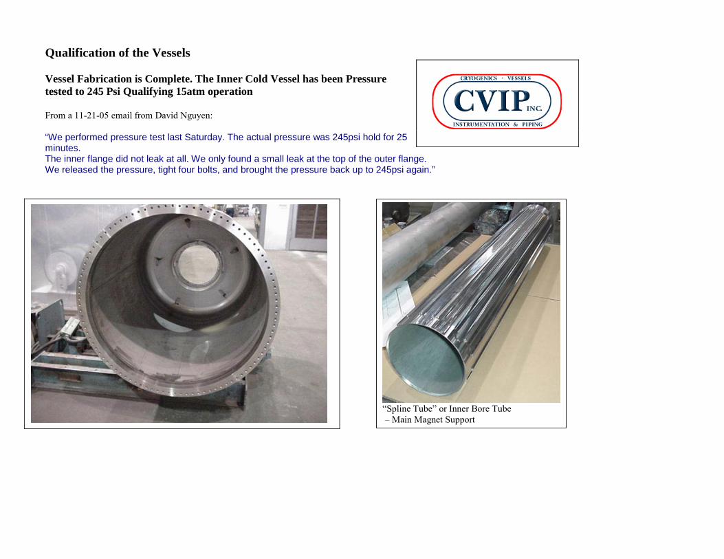
Qualification of the Vessels Vessel Fabrication is Complete. The Inner Cold Vessel has been Pressure tested to 245 Psi Qualifying 15atm operation From a 11-21-05 email from David Nguyen: “We performed pressure test last Saturday. The actual pressure was 245psi hold for 25 minutes. The inner flange did not leak at all. We only found a small leak at the top of the outer flange. We released the pressure, tight four bolts, and brought the pressure back up to 245psi again.”
“Spline Tube” or Inner Bore Tube – Main Magnet Support
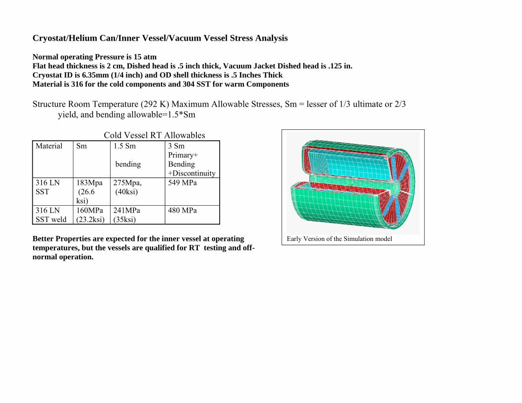
Cryostat/Helium Can/Inner Vessel/Vacuum Vessel Stress Analysis Normal operating Pressure is 15 atm Flat head thickness is 2 cm, Dished head is .5 inch thick, Vacuum Jacket Dished head is .125 in. Cryostat ID is 6.35mm (1/4 inch) and OD shell thickness is .5 Inches Thick Material is 316 for the cold components and 304 SST for warm Components Structure Room Temperature (292 K) Maximum Allowable Stresses, Sm = lesser of 1/3 ultimate or 2/3
yield, and bending allowable=1.5*Sm
Cold Vessel RT Allowables Material Sm 1.5 Sm
bending
3 Sm Primary+ Bending +Discontinuity
316 LN SST
183Mpa (26.6 ksi)
275Mpa, (40ksi)
549 MPa
316 LN SST weld
160MPa (23.2ksi)
241MPa (35ksi)
480 MPa
Better Properties are expected for the inner vessel at operating temperatures, but the vessels are qualified for RT testing and off-normal operation.
Early Version of the Simulation model
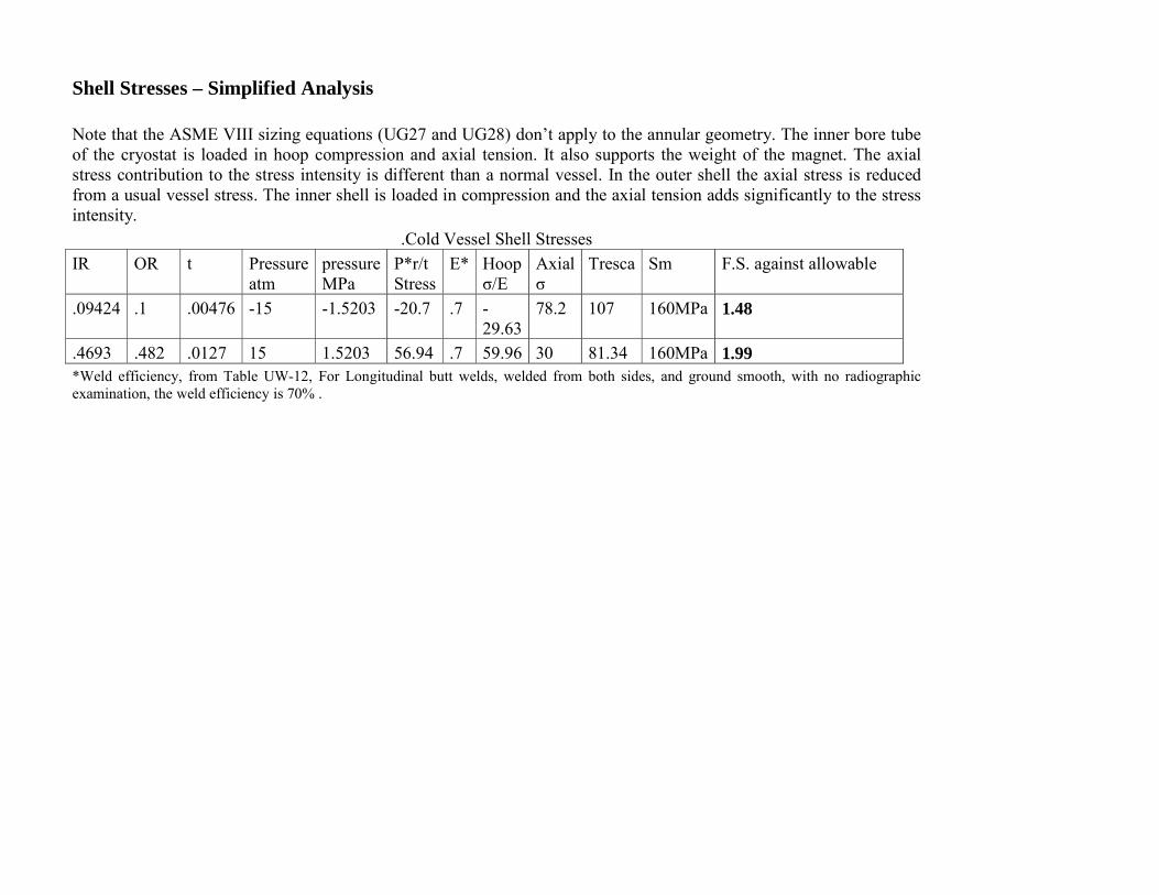
Shell Stresses – Simplified Analysis Note that the ASME VIII sizing equations (UG27 and UG28) don’t apply to the annular geometry. The inner bore tube of the cryostat is loaded in hoop compression and axial tension. It also supports the weight of the magnet. The axial stress contribution to the stress intensity is different than a normal vessel. In the outer shell the axial stress is reduced from a usual vessel stress. The inner shell is loaded in compression and the axial tension adds significantly to the stress intensity.
.Cold Vessel Shell Stresses IR OR t Pressure
atm pressure MPa
P*r/t Stress
E* Hoop σ/E
Axial σ
Tresca Sm F.S. against allowable
.09424 .1 .00476 -15 -1.5203 -20.7 .7 -29.63
78.2 107 160MPa 1.48
.4693 .482 .0127 15 1.5203 56.94 .7 59.96 30 81.34 160MPa 1.99 *Weld efficiency, from Table UW-12, For Longitudinal butt welds, welded from both sides, and ground smooth, with no radiographic examination, the weld efficiency is 70% .
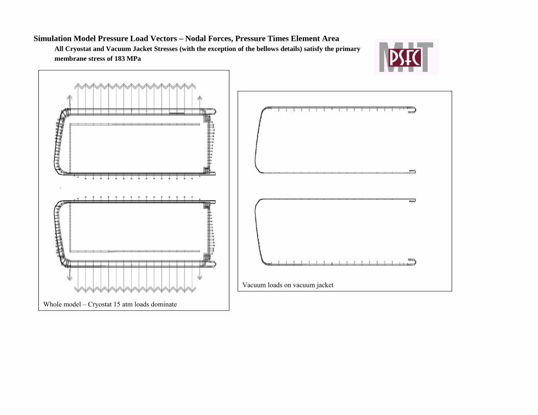
Simulation Model Pressure Load Vectors – Nodal Forces, Pressure Times Element Area All Cryostat and Vacuum Jacket Stresses (with the exception of the bellows details) satisfy the primary membrane stress of 183 MPa
Whole model – Cryostat 15 atm loads dominate
Vacuum loads on vacuum jacket
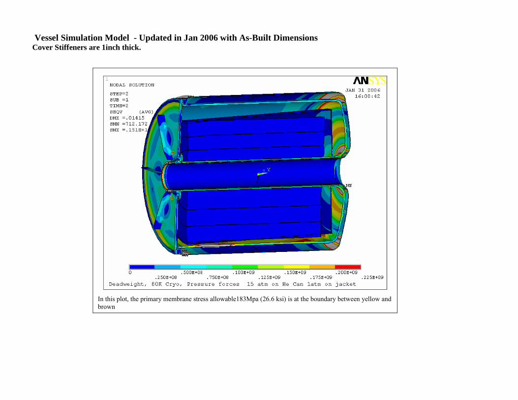
Vessel Simulation Model - Updated in Jan 2006 with As-Built Dimensions Cover Stiffeners are 1inch thick.
In this plot, the primary membrane stress allowable183Mpa (26.6 ksi) is at the boundary between yellow and brown
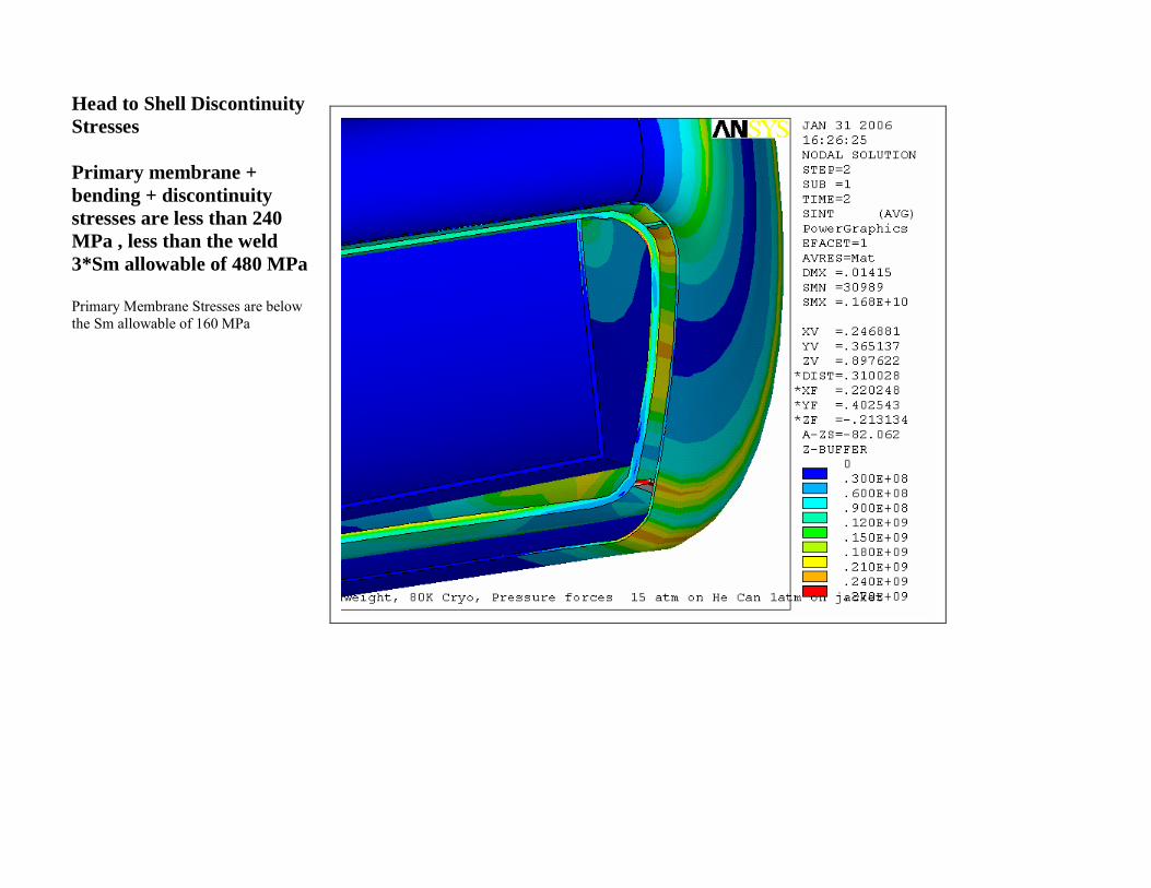
Head to Shell Discontinuity Stresses Primary membrane + bending + discontinuity stresses are less than 240 MPa , less than the weld 3*Sm allowable of 480 MPa Primary Membrane Stresses are below the Sm allowable of 160 MPa
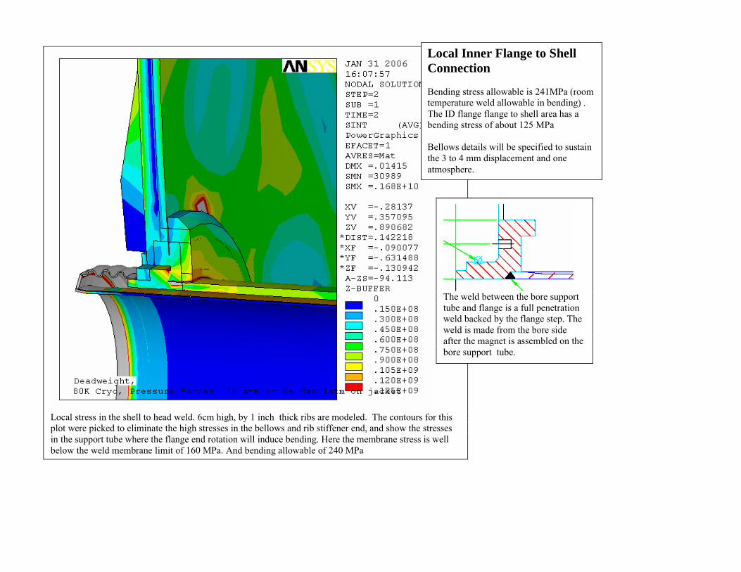
Local stress in the shell to head weld. 6cm high, by 1 inch thick ribs are modeled. The contours for this plot were picked to eliminate the high stresses in the bellows and rib stiffener end, and show the stresses in the support tube where the flange end rotation will induce bending. Here the membrane stress is well below the weld membrane limit of 160 MPa. And bending allowable of 240 MPa
The weld between the bore support tube and flange is a full penetration weld backed by the flange step. The weld is made from the bore side after the magnet is assembled on the bore support tube.
Local Inner Flange to Shell Connection Bending stress allowable is 241MPa (room temperature weld allowable in bending) . The ID flange flange to shell area has a bending stress of about 125 MPa Bellows details will be specified to sustain the 3 to 4 mm displacement and one atmosphere.
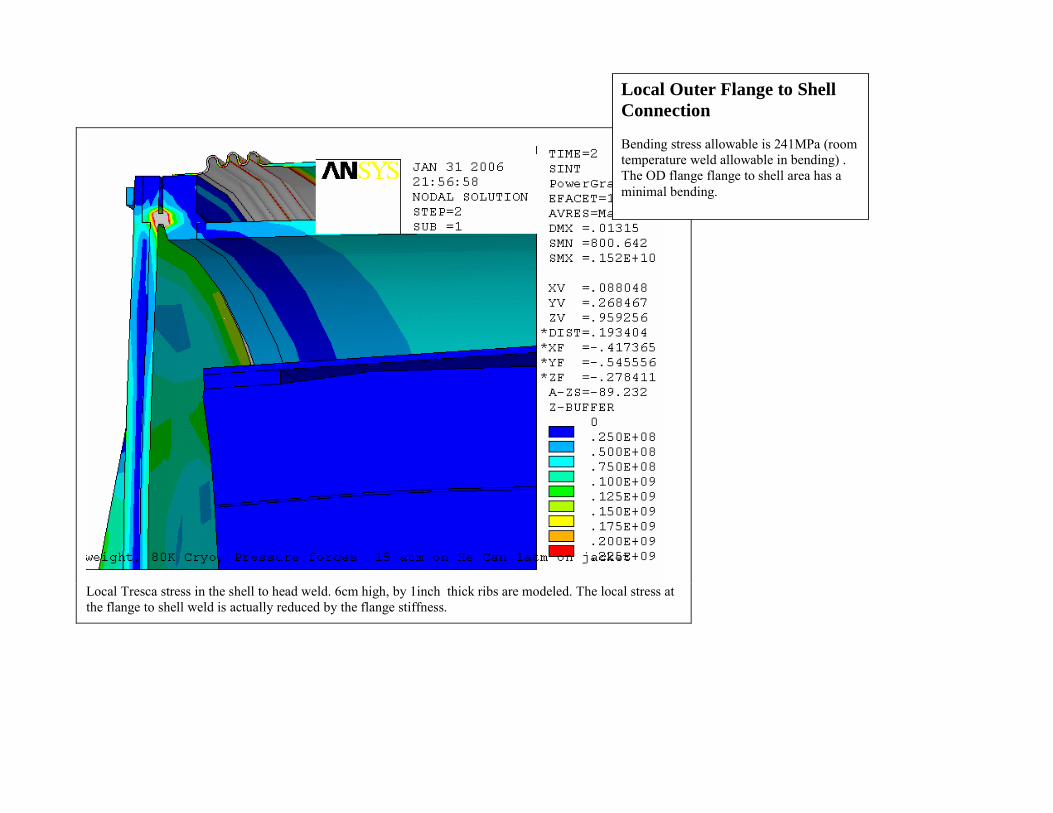
Local Tresca stress in the shell to head weld. 6cm high, by 1inch thick ribs are modeled. The local stress at the flange to shell weld is actually reduced by the flange stiffness.
Local Outer Flange to Shell Connection Bending stress allowable is 241MPa (room temperature weld allowable in bending) . The OD flange flange to shell area has a minimal bending.
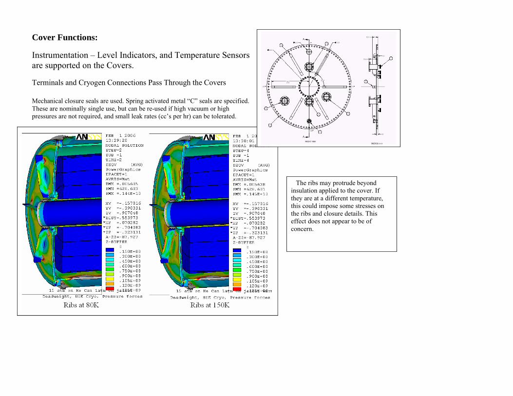
Cover Functions: Instrumentation – Level Indicators, and Temperature Sensors are supported on the Covers. Terminals and Cryogen Connections Pass Through the Covers Mechanical closure seals are used. Spring activated metal “C” seals are specified. These are nominally single use, but can be re-used if high vacuum or high pressures are not required, and small leak rates (cc’s per hr) can be tolerated.
The ribs may protrude beyond insulation applied to the cover. If they are at a different temperature, this could impose some stresses on the ribs and closure details. This effect does not appear to be of concern.
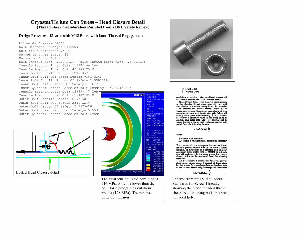
Cryostat/Helium Can Stress – Head Closure Detail (Thread Shear Consideration Resulted from a BNL Safety Review)
Design Pressure= 15 atm with M12 Bolts, with 8mm Thread Engagement Allowable Stress= 57000 Bolt Ultimate Strength= 110000 Bolt Yield Strength= 95000 Number of Inner Bolts: 24 Number of Outer Bolts: 96 Bolt Tensile Area= .13033826 Bolt Thread Shear Area= .50092224 Tensile Load on inner Cyl: 110378.99 lbs Tensile Load on inner Cyl: 491009.75 N Inner Bolt Tensile Stress 35286.067 Inner Bolt Pull Out Shear Stress 9181.3146 Inner Bolt Tensile Factor Of Safety 1.0391259 Inner Bolt Shear Factor Of Safety 1.1617 Inner Cylinder Stress Based on Bolt Loading 178.33716 MPa Tensile Load on outer Cyl: 138553.87 lbs Tensile Load on outer Cyl: 616342.83 N Outer Bolt Tensile Stress 10192.581 Outer Bolt Pull Out Stress 2881.2246 Outer Bolt Factor Of Safety 3.5973878 Outer Bolt Shear Factor of Safety= 5.5531943 Outer Cylinder Stress Based on Bolt Loading 20.309319 MPa
Bolted Head Closure detail
Excerpt from ref 15, the Federal Standards for Screw Threads, showing the recommended thread shear area for strong bolts in a weak threaded hole.
The axial tension in the bore tube is 116 MPa, which is lower than the bolt Basic program calculations predict (178 MPa). The reported inner bolt tension
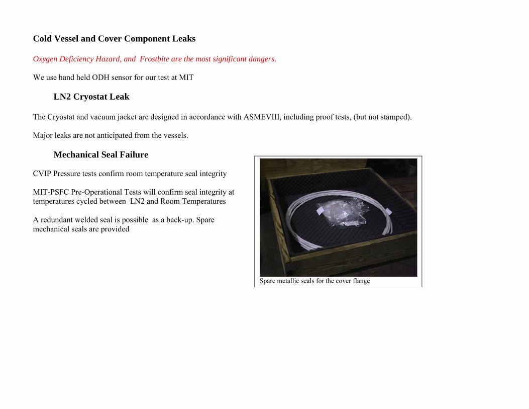
Cold Vessel and Cover Component Leaks Oxygen Deficiency Hazard, and Frostbite are the most significant dangers. We use hand held ODH sensor for our test at MIT LN2 Cryostat Leak The Cryostat and vacuum jacket are designed in accordance with ASMEVIII, including proof tests, (but not stamped). Major leaks are not anticipated from the vessels. Mechanical Seal Failure CVIP Pressure tests confirm room temperature seal integrity MIT-PSFC Pre-Operational Tests will confirm seal integrity at temperatures cycled between LN2 and Room Temperatures A redundant welded seal is possible as a back-up. Spare mechanical seals are provided
Spare metallic seals for the cover flange
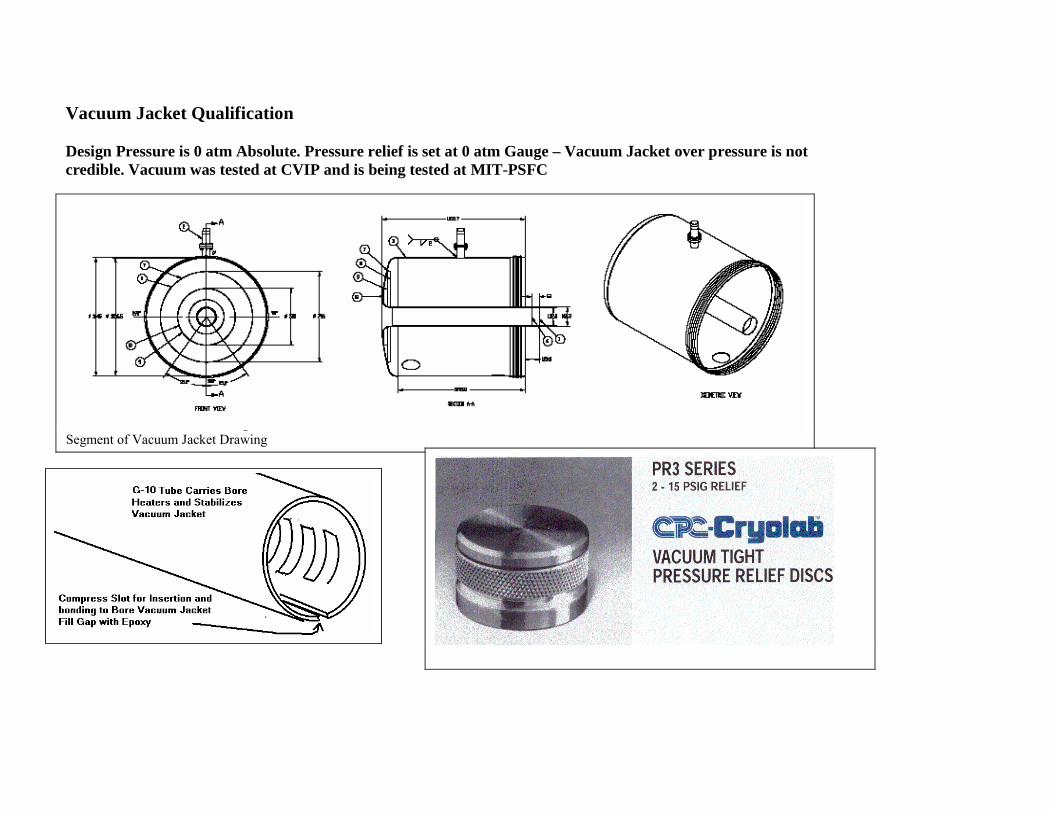
Vacuum Jacket Qualification Design Pressure is 0 atm Absolute. Pressure relief is set at 0 atm Gauge – Vacuum Jacket over pressure is not credible. Vacuum was tested at CVIP and is being tested at MIT-PSFC
Segment of Vacuum Jacket Drawing
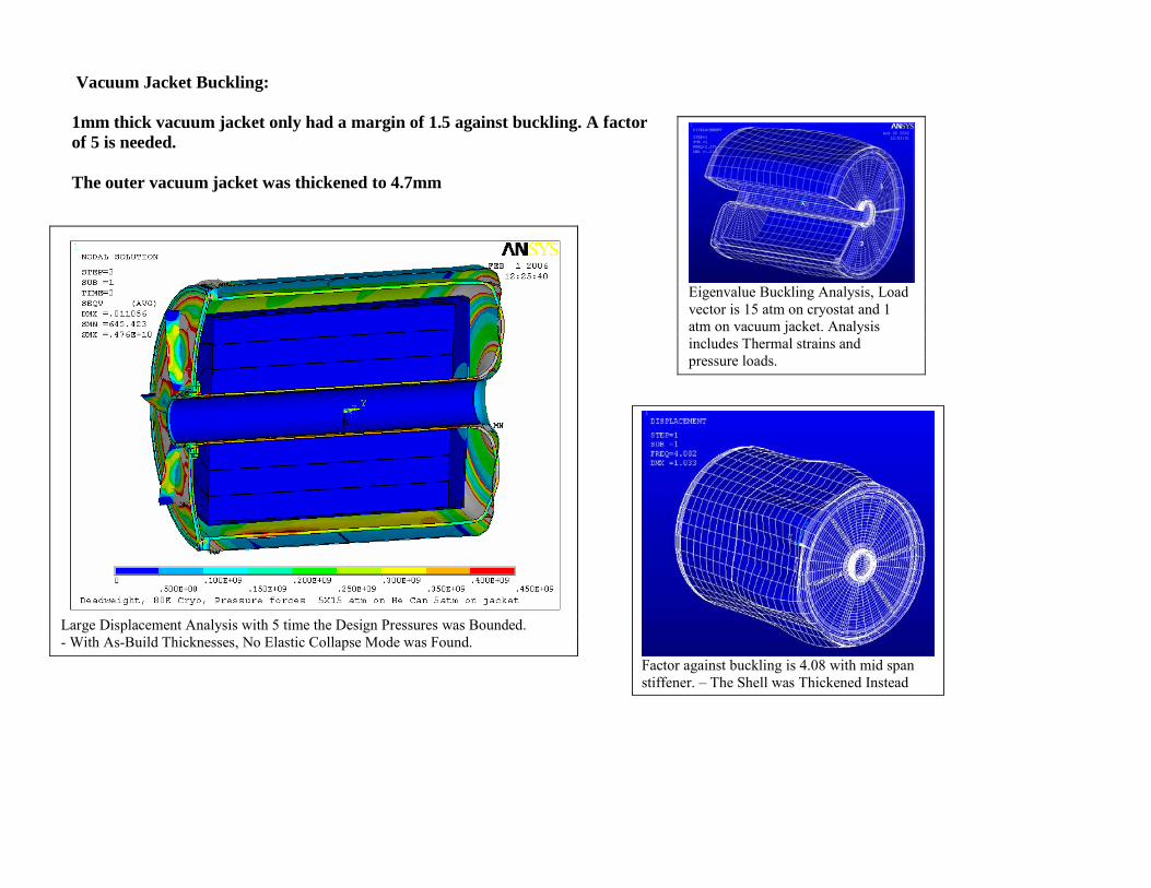
Vacuum Jacket Buckling: 1mm thick vacuum jacket only had a margin of 1.5 against buckling. A factor of 5 is needed. The outer vacuum jacket was thickened to 4.7mm
Eigenvalue Buckling Analysis, Load vector is 15 atm on cryostat and 1 atm on vacuum jacket. Analysis includes Thermal strains and pressure loads.
Large Displacement Analysis with 5 time the Design Pressures was Bounded. - With As-Build Thicknesses, No Elastic Collapse Mode was Found.
Factor against buckling is 4.08 with mid span stiffener. – The Shell was Thickened Instead
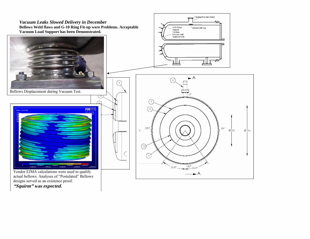
Vacuum Leaks Slowed Delivery in December Bellows Weld flaws and G-10 Ring Fit-up were Problems. Acceptable Vacuum Load Support has been Demonstrated.
Vendor EJMA calculations were used to qualify actual bellows. Analyses of “Postulated” Bellows designs served as an existence proof. “Squirm” was expected.
Bellows Displacement during Vacuum Test.
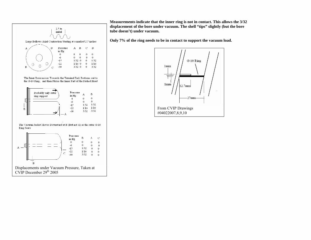
Measurements indicate that the inner ring is not in contact. This allows the 3/32 displacement of the bore under vacuum. The shell “tips” slightly (but the bore tube doesn’t) under vacuum. Only 7% of the ring needs to be in contact to support the vacuum load.
Displacements under Vacuum Pressure, Taken at CVIP December 29th 2005
From CVIP Drawings #04022007,8,9,10
Vacuum Space Leaks Bellows Crack These need to be specified conservatively with respect to displacement, and pressure rating. Axial displacement of the bore bellows, and lateral and radial displacements of the bellows support feet are both around 3mm. Unfortunately there were some problems with leaks in the bellows. Bellows leaks introduce air into the vacuum jacket space and degrade insulating properties. More LN2 will boil off, and Liquid may accumulate on the cold vessel and in the MLI that might pressurize the vacuum space – pressure relief is provided.
Leak Related Specification Content:
Sniffing Tests During Manufacture The following shall be performed in the prescribed order: 1) Confirm the sensitivity of sniffer is better than 5 x 10⁻⁵ std atm-cc/second helium with a calibrated helium source. 2) Use an appropriate temporary cover to close the vessel / volume, and introduce helium gas into the test volume without cracking the
temporary seal. 3) Confirm the background helium reading is below the sensitivity of the sniffer. 4) Spot leak checking shall be performed by inserting the sniffer in the envelop, which covers the outer surface of the joint area. 5) At high background helium count, consider isolating the first envelop from the background with a second envelope, which is flushed with
nitrogen gas. 6) Remove leak checking attachments and clean up the surface. Flush out helium gas if necessary.
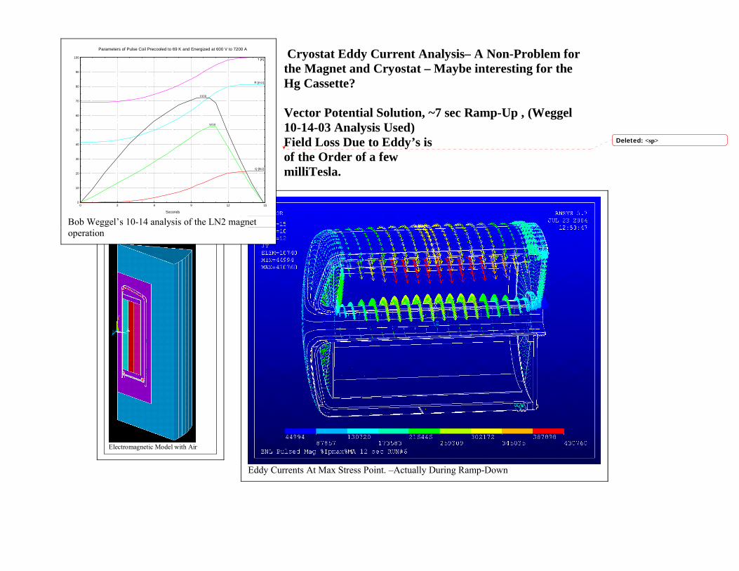
Cryostat Eddy Current Analysis– A Non-Problem for the Magnet and Cryostat – Maybe interesting for the Hg Cassette? Vector Potential Solution, ~7 sec Ramp-Up , (Weggel 10-14-03 Analysis Used) Field Loss Due to Eddy’s is of the Order of a few milliTesla.
Eddy Currents At Max Stress Point. –Actually During Ramp-Down
Electromagnetic Model with Air
0
10
20
30
40
50
60
70
80
90
100
0 3 6 9 12 15
Q [MJ]
V/10
R [mΩ]
I/100
T [K]
Seconds
Parameters of Pulse Coil Precooled to 69 K and Energized at 600 V to 7200 A
Bob Weggel’s 10-14 analysis of the LN2 magnet operation
Deleted: <sp>
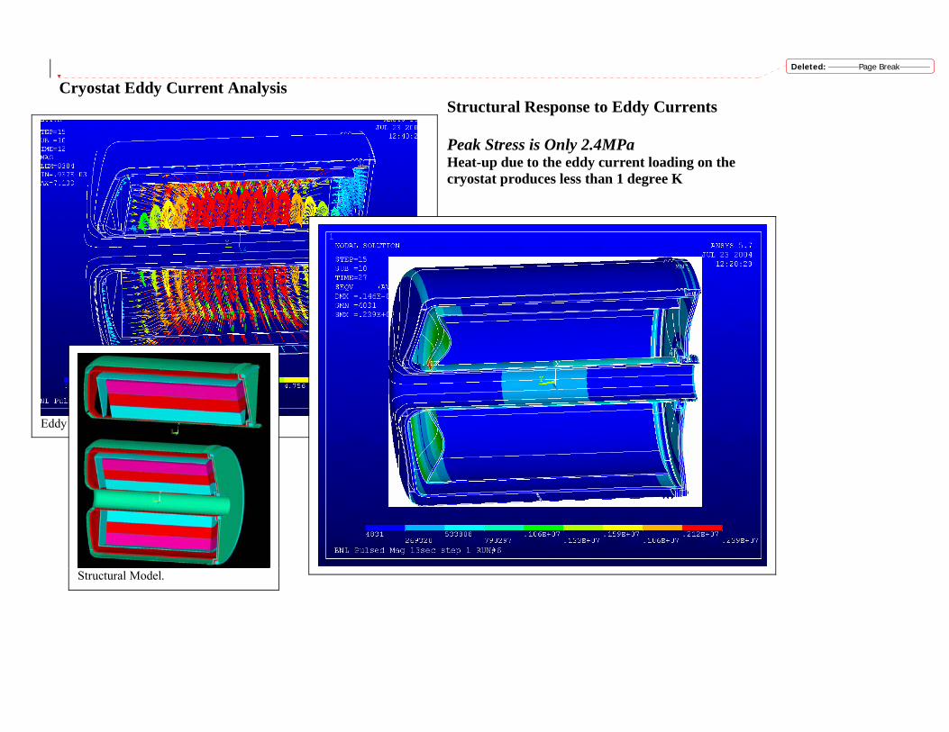
Cryostat Eddy Current Analysis
Structural Response to Eddy Currents Peak Stress is Only 2.4MPa Heat-up due to the eddy current loading on the cryostat produces less than 1 degree K
Eddy Current Forces During Ramp-Down
Structural Model.
Deleted: Page Break
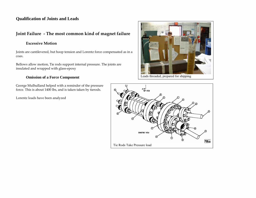
Qualification of Joints and Leads Joint Failure - The most common kind of magnet failure Excessive Motion Joints are cantilevered, but hoop tension and Lorentz force compensated as in a coax. Bellows allow motion, Tie rods support internal pressure. The joints are insulated and wrapped with glass-epoxy Omission of a Force Component George Mulhulland helped with a reminder of the pressure force. This is about 1400 lbs, and is taken taken by tierods. Lorentz loads have been analyzed
Leads threaded, prepared for shipping
Tie Rods Take Pressure load
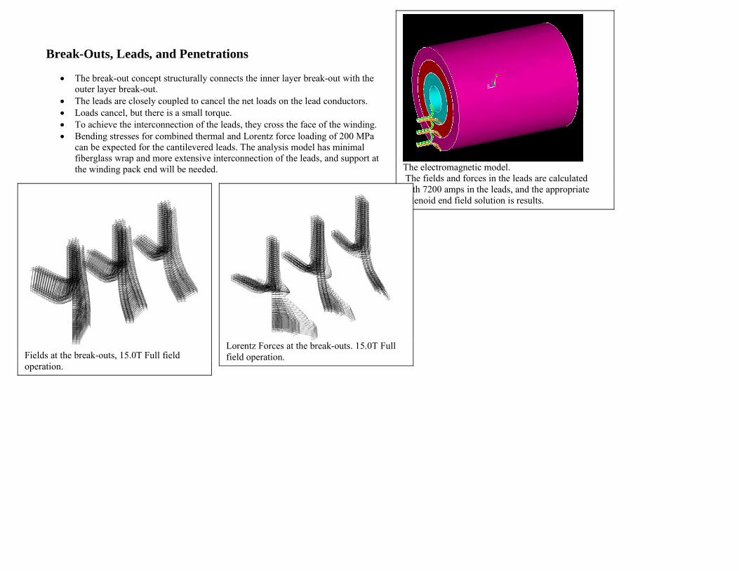
Break-Outs, Leads, and Penetrations
• The break-out concept structurally connects the inner layer break-out with the outer layer break-out.
• The leads are closely coupled to cancel the net loads on the lead conductors. • Loads cancel, but there is a small torque. • To achieve the interconnection of the leads, they cross the face of the winding. • Bending stresses for combined thermal and Lorentz force loading of 200 MPa
can be expected for the cantilevered leads. The analysis model has minimal fiberglass wrap and more extensive interconnection of the leads, and support at the winding pack end will be needed.
The electromagnetic model. The fields and forces in the leads are calculated with 7200 amps in the leads, and the appropriate solenoid end field solution is results.
Fields at the break-outs, 15.0T Full field operation.
Lorentz Forces at the break-outs. 15.0T Full field operation.
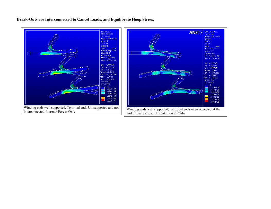
Break-Outs are Interconnected to Cancel Loads, and Equilibrate Hoop Stress.
Winding ends well supported, Terminal ends Un-supported and not interconnected. Lorentz Forces Only
Winding ends well supported, Terminal ends interconnected at the end of the lead pair. Lorentz Forces Only
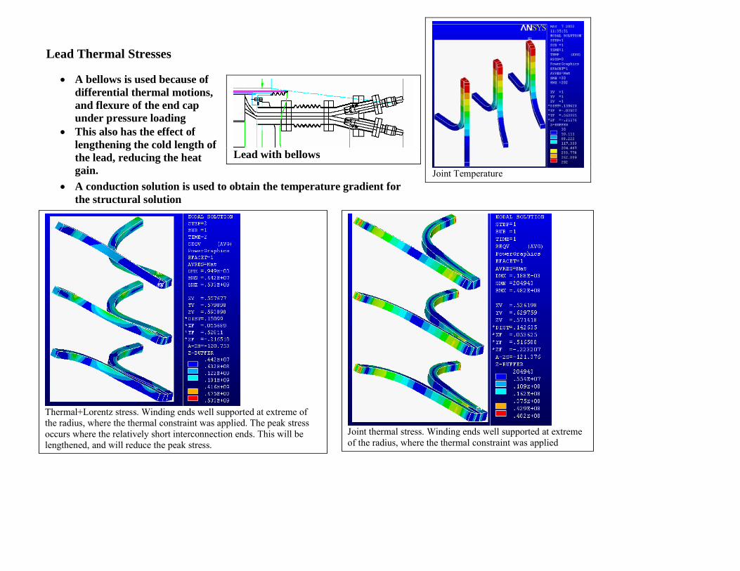
Lead Thermal Stresses
• A bellows is used because of differential thermal motions, and flexure of the end cap under pressure loading
• This also has the effect of lengthening the cold length of the lead, reducing the heat gain.
• A conduction solution is used to obtain the temperature gradient for the structural solution
Joint Temperature
Lead with bellows
Joint thermal stress. Winding ends well supported at extreme of the radius, where the thermal constraint was applied
Thermal+Lorentz stress. Winding ends well supported at extreme of the radius, where the thermal constraint was applied. The peak stress occurs where the relatively short interconnection ends. This will be lengthened, and will reduce the peak stress.
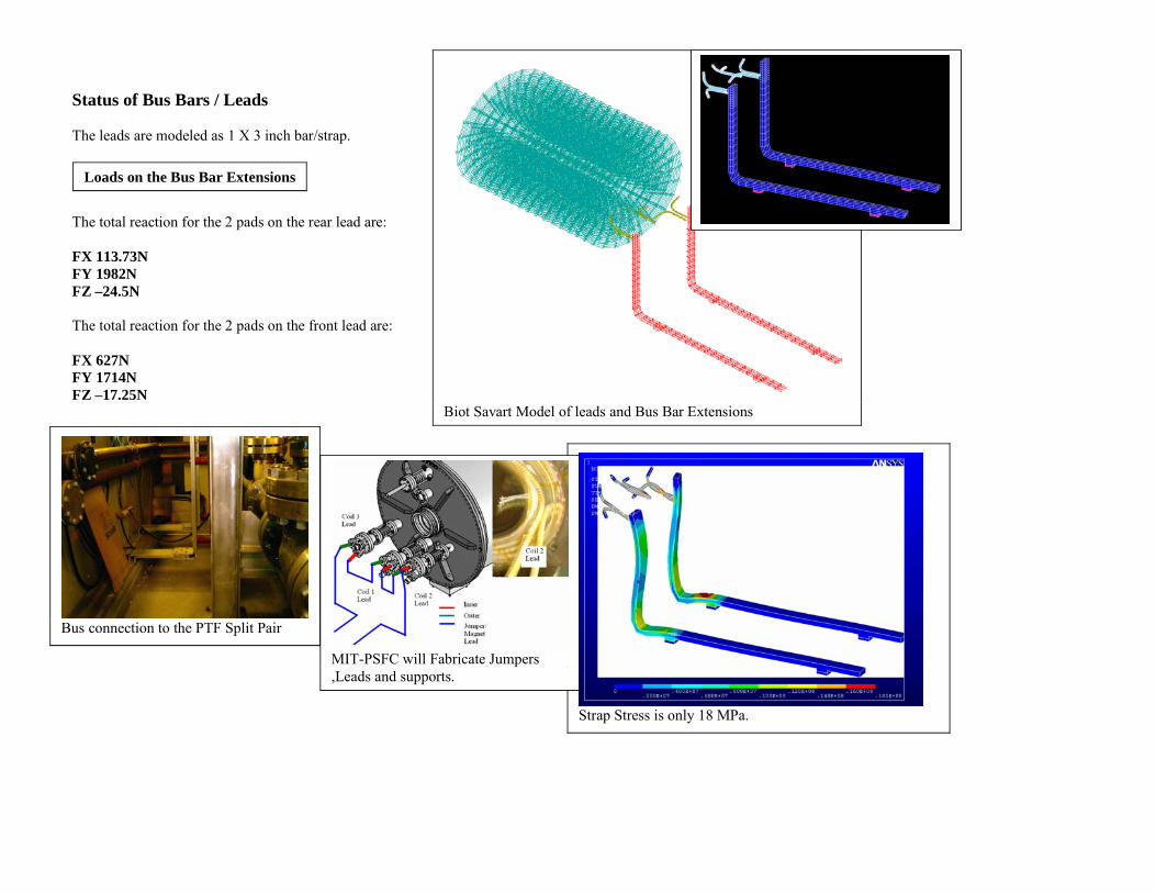
Status of Bus Bars / Leads The leads are modeled as 1 X 3 inch bar/strap.
The total reaction for the 2 pads on the rear lead are: FX 113.73N FY 1982N FZ –24.5N The total reaction for the 2 pads on the front lead are: FX 627N FY 1714N FZ –17.25N
Biot Savart Model of leads and Bus Bar Extensions
Loads on the Bus Bar Extensions
Strap Stress is only 18 MPa.
Bus connection to the PTF Split Pair
MIT-PSFC will Fabricate Jumpers ,Leads and supports.
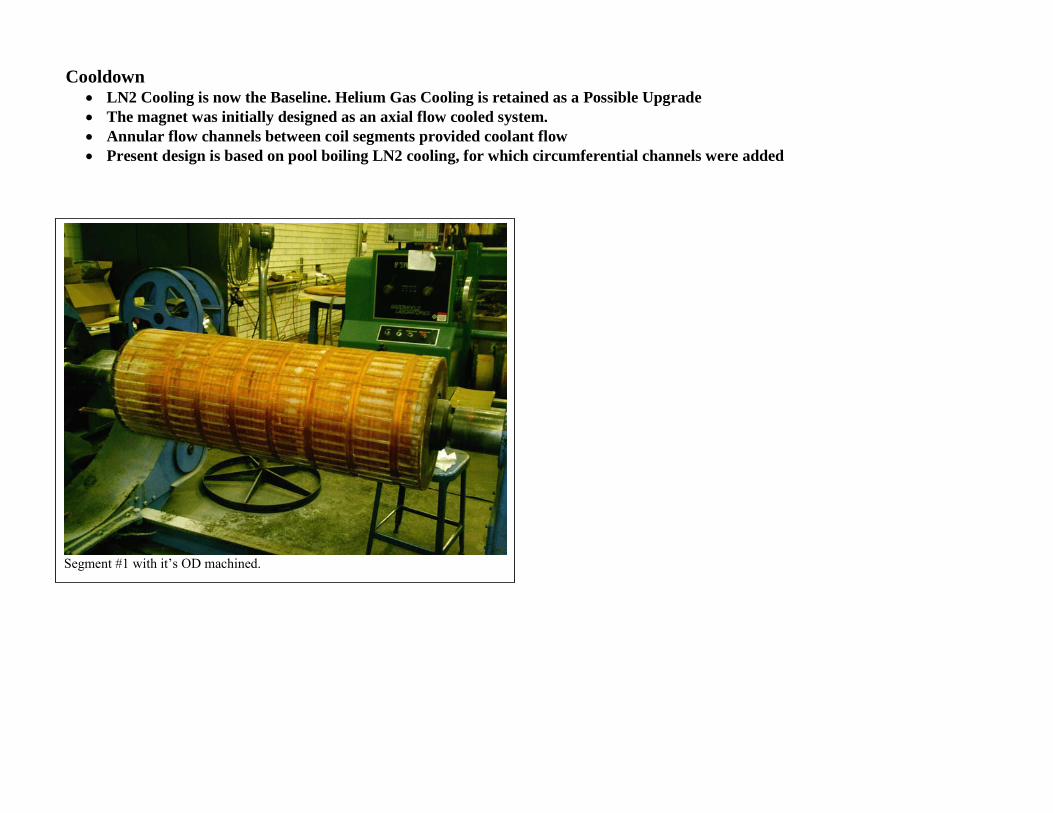
Cooldown • LN2 Cooling is now the Baseline. Helium Gas Cooling is retained as a Possible Upgrade • The magnet was initially designed as an axial flow cooled system. • Annular flow channels between coil segments provided coolant flow • Present design is based on pool boiling LN2 cooling, for which circumferential channels were added
Segment #1 with it’s OD machined.
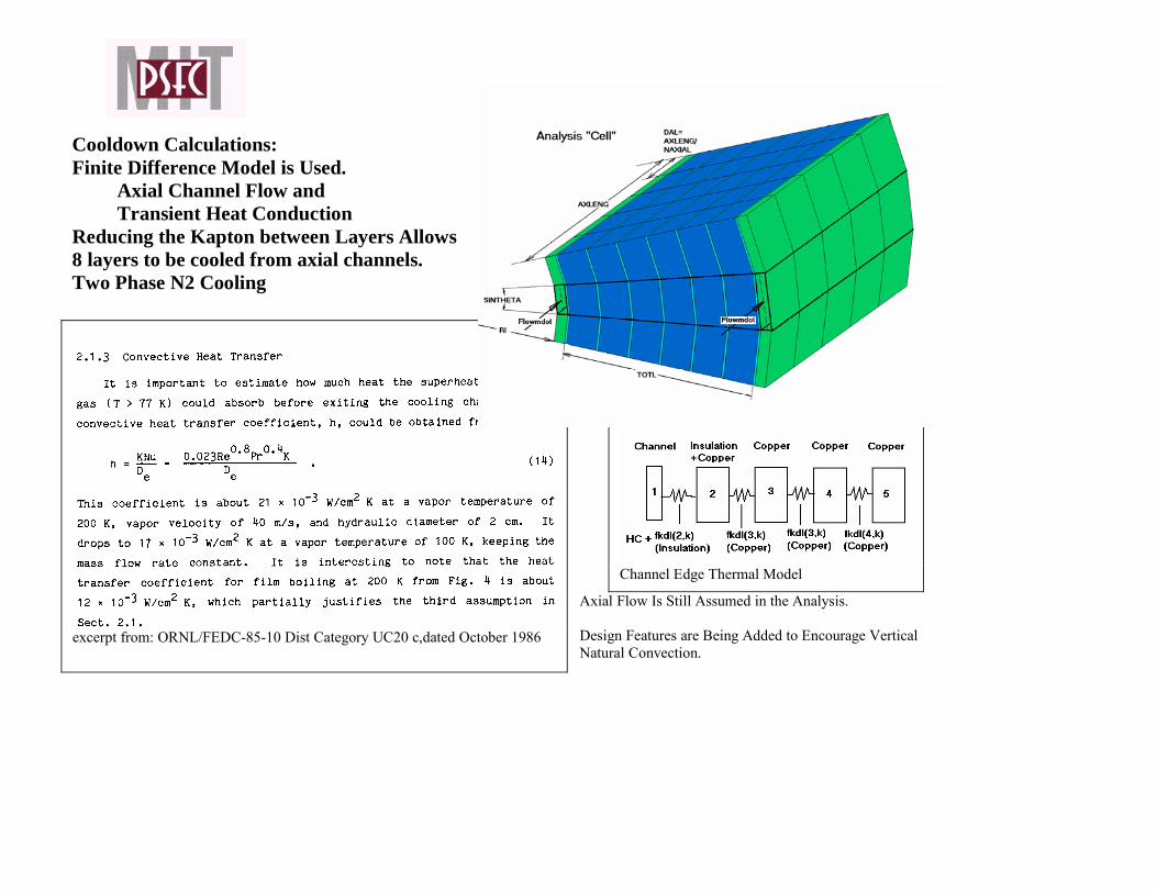
Cooldown Calculations: Finite Difference Model is Used.
Axial Channel Flow and Transient Heat Conduction
Reducing the Kapton between Layers Allows 8 layers to be cooled from axial channels. Two Phase N2 Cooling
Axial Flow Is Still Assumed in the Analysis. Design Features are Being Added to Encourage Vertical Natural Convection.
Channel Edge Thermal Model
excerpt from: ORNL/FEDC-85-10 Dist Category UC20 c,dated October 1986
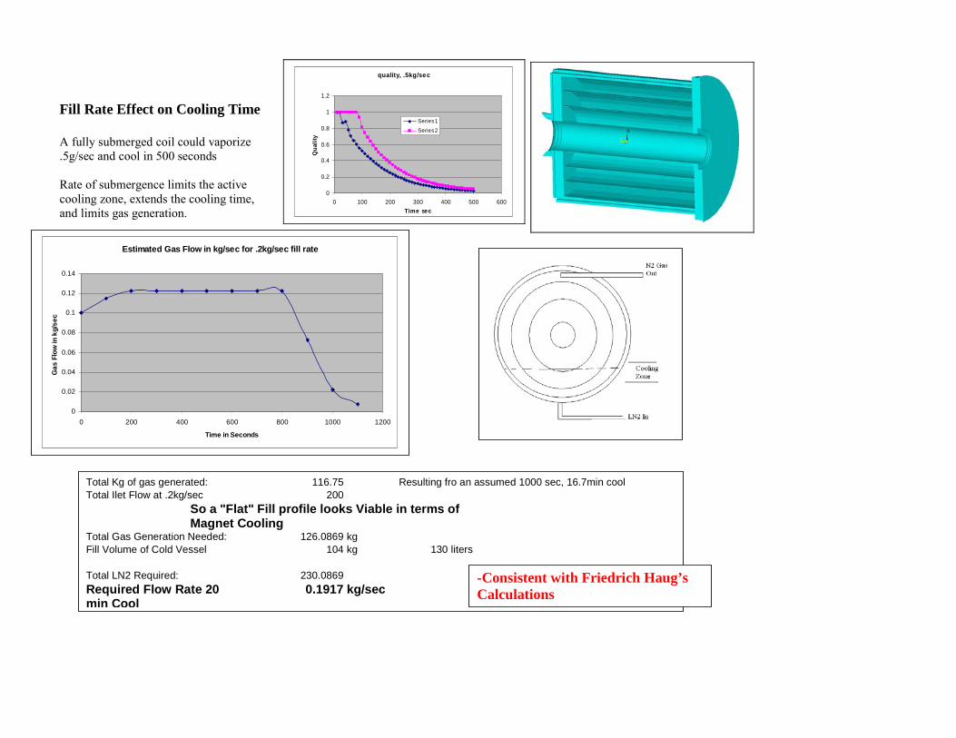
Fill Rate Effect on Cooling Time A fully submerged coil could vaporize .5g/sec and cool in 500 seconds Rate of submergence limits the active cooling zone, extends the cooling time, and limits gas generation.
quality, .5kg/sec
0
0.2
0.4
0.6
0.8
1
1.2
0 100 200 300 400 500 600Time sec
Qua
lity
Series1
Series2
Estimated Gas Flow in kg/sec for .2kg/sec fill rate
0
0.02
0.04
0.06
0.08
0.1
0.12
0.14
0 200 400 600 800 1000 1200
Time in Seconds
Gas
Flo
w in
kg/
sec
Total Kg of gas generated: 116.75 Resulting fro an assumed 1000 sec, 16.7min cool Total Ilet Flow at .2kg/sec 200
So a "Flat" Fill profile looks Viable in terms of Magnet Cooling
Total Gas Generation Needed: 126.0869 kg Fill Volume of Cold Vessel 104 kg 130 liters
Total LN2 Required: 230.0869Required Flow Rate 20 min Cool
0.1917 kg/sec -Consistent with Friedrich Haug’s Calculations
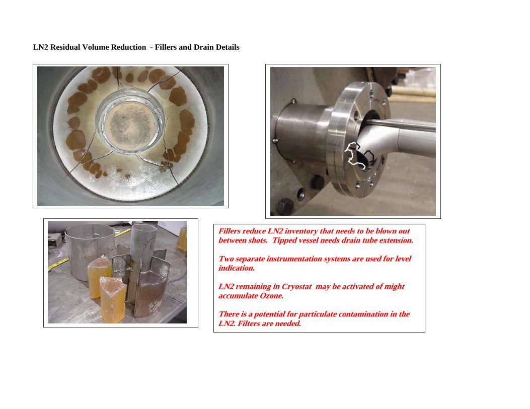
LN2 Residual Volume Reduction - Fillers and Drain Details
Fillers reduce LN2 inventory that needs to be blown out between shots. Tipped vessel needs drain tube extension. Two separate instrumentation systems are used for level indication. LN2 remaining in Cryostat may be activated of might accumulate Ozone. There is a potential for particulate contamination in the LN2. Filters are needed.
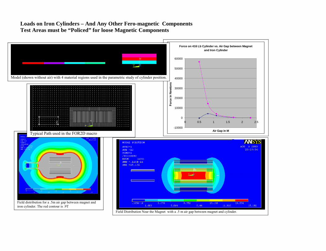
Loads on Iron Cylinders – And Any Other Fero-magnetic Components Test Areas must be “Policed” for loose Magnetic Components
Force on 416 Lb Cylinder vs. Air Gap between Magnet and Iron Cylinder
-10000
0
10000
20000
30000
40000
50000
60000
0 0.5 1 1.5 2 2.5
Air Gap in M
Forc
e in
New
tons
Model (shown without air) with 4 material regions used in the parametric study of cylinder position.
Field distribution for a .5m air gap between magnet and iron cylinder. The red contour is .9T
Field Distribution Near the Magnet with a .5 m air gap between magnet and cylinder.
Typical Path used in the FOR2D macro
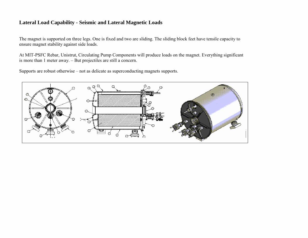
Lateral Load Capability - Seismic and Lateral Magnetic Loads The magnet is supported on three legs. One is fixed and two are sliding. The sliding block feet have tensile capacity to ensure magnet stability against side loads. At MIT-PSFC Rebar, Unistrut, Circulating Pump Components will produce loads on the magnet. Everything significant is more than 1 meter away. – But projectiles are still a concern. Supports are robust otherwise – not as delicate as superconducting magnets supports.
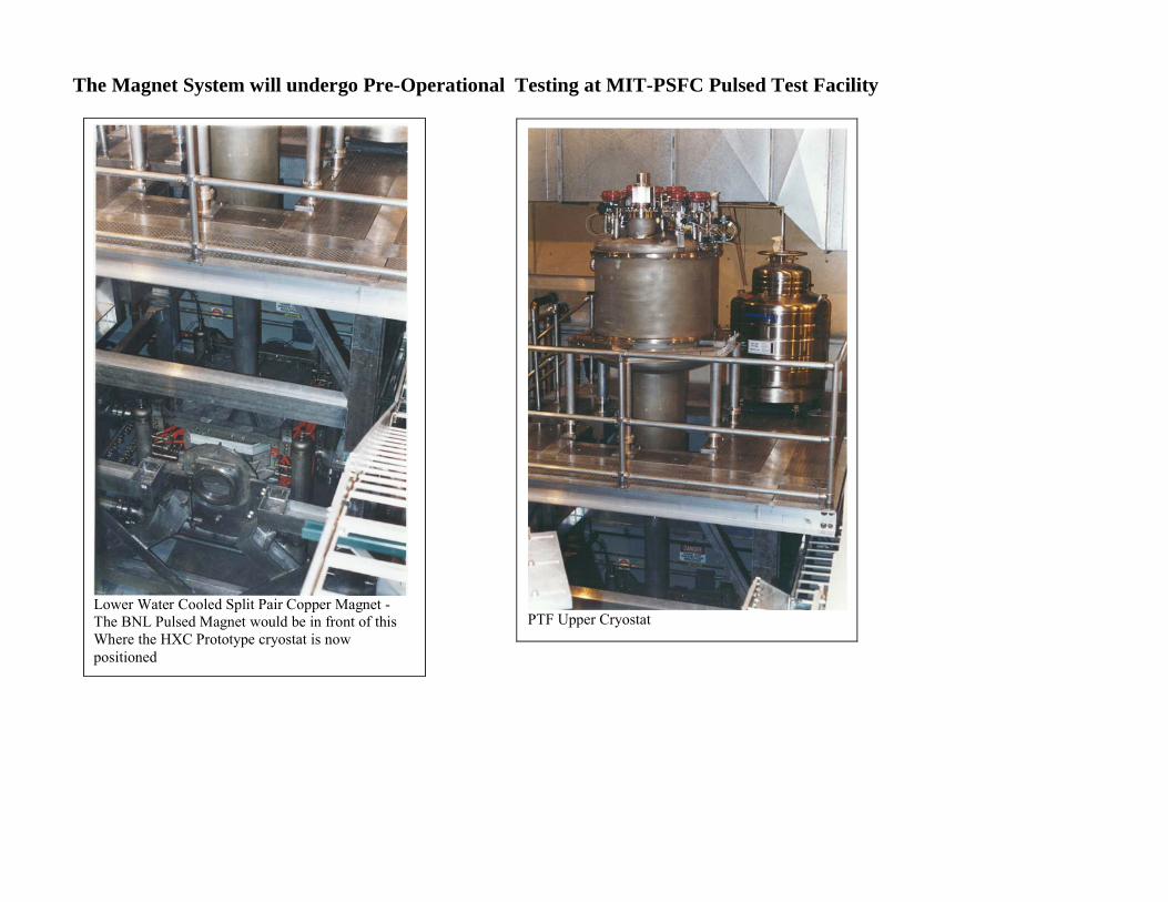
The Magnet System will undergo Pre-Operational Testing at MIT-PSFC Pulsed Test Facility
PTF Upper Cryostat
Lower Water Cooled Split Pair Copper Magnet - The BNL Pulsed Magnet would be in front of this Where the HXC Prototype cryostat is now positioned
Conclusion CERN will receive an extensively analyzed and tested magnet system for use in the MERIT Experiment. It has been qualified in accordance with the best practices available for unique magnet systems. Testing Procedures, Results; Drawings, and Calculations are available at: http://www.psfc.mit.edu/people/titus/#BNL%20Memos