Embed Size (px)
Citation preview

CERN Chopper StatusCERN Chopper Status
F. Caspers, M. Paoluzzi
CERN, HIPPI 08 meeting October 29th, 2008

Caspers,Paoluzzi CERN chopper status October 2008CERN HIPPI meeting October 2008 2
Introduction CERN chopping scheme Layout Technical requirements
Evolution of the SPL chopper Modifications in 2005 Status by September 2006
What happend since end of 2006 Status by April 2008 Some photos What is still to be done
Drivers StatusDrivers Status AcknowledgementsAcknowledgements
ContentsContents
Most of these slides were already shown in May 2008 at the WP4 meetingMost of these slides were already shown in May 2008 at the WP4 meeting

Caspers,Paoluzzi CERN chopper status October 2008CERN HIPPI meeting October 2008 3
Superconducting Proton Linac (SPL) Fast beam chopping at Ekin = 3 MeV ; thus is about 8%
Fast chopper required to establish desired beam pattern
SPL LayoutSPL Layout
RFQ: Radio frequency quadrupole DTL: Drift tube linac CCDTL: Coupled cavity DTL PIMS (PI-Mode Structure) = 0.65, = 0.92 : superconducting cavities

Caspers,Paoluzzi CERN chopper status October 2008CERN HIPPI meeting October 2008 4
8*2.84 ns ( 44 MHz)
Most demanding scheme for SPL operation: cutting out three bunches out of eight repetition rate 44 MHz bunch spacing 2.84 ns ; 10 to 90% rise and fall time required < 2 ns
CERN Chopping SchemeCERN Chopping Scheme

Caspers,Paoluzzi CERN chopper status October 2008CERN HIPPI meeting October 2008 5
Chopper off
Chopper line lattice designed such as to magnify the kick from the chopper; this reduces required kick field
The chopper plates have to be installed in the quads; this saves length and reduces space-charge related emittance growth
Chopper Line (1)Chopper Line (1)
Chopper on
Kick-magnifying quad

Caspers,Paoluzzi CERN chopper status October 2008
CERN HIPPI meeting October 2008 6
Chopper Line (2)Chopper Line (2)
chopper beam dump
bunching cavities

Caspers,Paoluzzi CERN chopper status October 2008CERN HIPPI meeting October 2008 7
The chopper plates are no longer DC-wise floating (no more triaxial mode of operation)
Now we have a coaxial instead of a triaxial chopper structure
The triaxial version was meant for simultaneous dual mode of operation, i.e. 0 to 10 MHz: electrostatic deflector, above 10 MHz travelling wave mode
Removal of isolating units both in water cooling circuits and coaxial driving lines
Modifications in 2005Modifications in 2005

Caspers,Paoluzzi CERN chopper status October 2008CERN HIPPI meeting October 2008 8
Initially samples of the meander lines were produced at CERN While all parameters were basically ok (electrical, vacuum),
reproducibility of certain electrical parameters (electrical length, match) was not always perfectly satisfactory
After the accomplished proof of principle with CERN technology, a supplier that can well control all the process parameters was needed; a possible change in technology is not a problem as long as the key properties are preserved
Kyocera was eager to enter in a cooperation with CERN and willing to adapt their technology to our needs
The plate that was recently furnished compared well in all aspects with the best CERN samples and we hope that the promised good reproducibility will show up in reality
Meander linesMeander lines

Caspers,Paoluzzi CERN chopper status October 2008CERN HIPPI meeting October 2008 9
Technological differences between the CERN and Kyocera meander structures:
Meander line: TechnologyMeander line: Technology
CERN Kyocera
CERN orders from Wesgo (D) ceramic plates with fixation holes and 10 to 15 m thick homogeneous MoMn layer (fired at 1400 C in hydrogen atmosphere
Kyocera produces the alumina plates in-house. Then a meander pattern is created in thick film silver paste of about 10 to 15 m thickness. This thick film silver paste has after firing a much higher resistivity than bulk silver (factor 5 to 10)
The meander structure is etched into the MoMn layer. Afterwards a 1 to 2 m thin-film layer of Ag is attached by sputtering.
Onto the Ag thick-film layer 30 to 40 m copper are deposited electrochemically
In a final step this silver-coated MoMn layer gets another 30 m silver by electrochemical deposition
Finally 1 to 2 m of Au are applied for good contacts and protection against oxidation
In the meantime (october 2008) I learned that it is possible to produce nonmagnetic Nickel layers by adding 18 % of phosphor [F.C.]
Caspers,Paoluzzi CERN chopper status October 2008CERN HIPPI meeting October 2008 10
Metallize printing (Ag thick-film)
Firing
Cu Plating
Resistance Testing
Final inspection
Packing
Machining
Ceramic incominginspection
Au Plating
CERAMIC PLATE Process Flow CERAMIC PLATE Process Flow
RF Property Testing
Machining
Electrode for electrochemical deposition removed by grinding
Grinding Area
Courtesy: Kyocera

Caspers,Paoluzzi CERN chopper status October 2008CERN HIPPI meeting October 2008 11
First meander line plate from Kyocera were received in June 2006 but it turned out that the attenuation was too high
In the second iteration the technological parameters were properly adjusted and the last sample was very satisfactory
After extensive electrical tests this single plate was installed in the chopper tank
Vacuum, leak and heat tests performed successfully
Status by September 2006Status by September 2006

Caspers,Paoluzzi CERN chopper status October 2008CERN HIPPI meeting October 2008 12
Electric Measurements: Electric Measurements: Transmission AttenuationTransmission Attenuation
Measurements performed on single chopper plate with an image plane 10 mm above the line’s surface to simulate the presence of a second plate
Frequency domain transmission A DC resistance of 1.1 was
measured, which agrees very well with the low-frequency limit of the measured attenuation
3 dB bandwidth 940 MHz. If there was no phase distortion the rise time would be
All rise times quoted are 10 to 90% values ns 355.0
3
1
BWtt
Attenuation over one chopper plate
Gen
erat
or b
andw
idth

Caspers,Paoluzzi CERN chopper status October 2008CERN HIPPI meeting October 2008 13
Transmission Step ResponseTransmission Step Response Response for 0 to 700 MHz low pass
step function (Kaiser Bessel weighting function with = 6)
Comparison between a measurement with and without the image plane. Due to the high electric field energy in the alumina the kick field does not change much when the symmetry is broken
Measured rise time trm = 1.771 ns, to be compared with tri = 1.407 ns of input pulse; structure rise time
This is a conservative estimate of tr since the tti is rather short and we get into the highly dispersive region of the response
ns 08.122 rirmr ttt

Caspers,Paoluzzi CERN chopper status October 2008CERN HIPPI meeting October 2008 14
Phase DistortionPhase Distortion
From the measured phase without image plate the electrical delay of 16.73 ns (linear term) was removed
With image plane (realistic configuration) the electrical length was 16.83 ns, within 0.1 ns of the required value
The remaining phase is not flat as for a dispersion-free line; thus we have phase distortion
The phase distortion is due to coupling between adjacent lines in the meander structure. This coupling increases quickly with frequency like in a microstrip directional coupler
In an ordinary first-order low-pass the 45 degree points coincide with the 3 dB points. Here they are at 375 MHz, i.e. much lower than the 3 dB points
Gen
erat
or b
andw
idth
Phase without image plane
Caspers,Paoluzzi CERN chopper status October 2008CERN HIPPI meeting October 2008 15
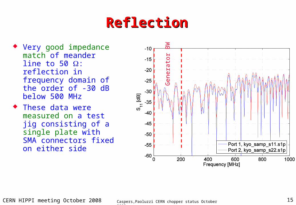
ReflectionReflection
Very good impedance match of meander line to 50 : reflection in frequency domain of the order of -30 dB below 500 MHz
These data were measured on a test jig consisting of a single plate with SMA connectors fixed on either side
Gen
erat
or B
W

Caspers,Paoluzzi CERN chopper status October 2008CERN HIPPI meeting October 2008 16
Reflection Step ResponseReflection Step Response
Response for 0 to 700 MHz low pass step function
S11 very small, of the order of 0.02 which is another indication of good match
The line impedance is not perfectly constant over the meander length as can be seen from the bump at t = 10 ns.
Towards the end of the line an apparent increase in line impedance can be seen. This is an artifact caused by the lossy line; could be corrected numerically
Twice the line length of ¼17 ns

Caspers,Paoluzzi CERN chopper status October 2008CERN HIPPI meeting October 2008 17
Tuning of Electrical LengthTuning of Electrical Length
It was tried to adjust the electrical delay of a chopper plate by modifying the metal ground plane
Cutting a longitudinal groove into the ground plane reduces the effective and thus increases the group velocity on the line. Since the variation in line impedance is over distances much shorter than the wavelength, the other electrical properties should not be affected much
For two 5 mm wide and 3 mm deep grooves a 5% decrease in the electrical length was found on a CERN plate
Gen
erat
or b
andw
idth

Caspers,Paoluzzi CERN chopper status October 2008CERN HIPPI meeting October 2008 18
What happend since end of 2006 ? (1)What happend since end of 2006 ? (1)
We have seen that the originally used aluminum support plates for the alumina ceramic are not usable since they liberate internal stress when heated and show considerable deformation ( up to several 100 micron); this has even led to the destruction of ceramic substrates when mounted (fortunately only old ones, which we were allowed to destroy)
This deformation is a very critical issue since the thermal contact betwen the ceramic plate and the metal support depends strongly on the small vacuum gap between the ceramic and the metal.
In fact this point has been subject of many discussions and the heat transfer between the ceramic and metal plate is essentially an electromagnetic tunneling effect !
The wavelength corresponding to room temperature is about 10 micron we the average space between metal and ceramic plate has to be below a few microns in order to meet the tunneling condition (similar to a microwave waveguide below cutoff signal transmission)

Caspers,Paoluzzi CERN chopper status October 2008CERN HIPPI meeting October 2008 19
What happend since end of 2006 ? (2)What happend since end of 2006 ? (2)
Thus it was decided to replace those aluminum plates by stainless steel plates which are heat treated (to release all internal stresses) and copper coated (without using nickel as intermediate layer [magnetic field!) and finally having a flash of gold to prevent oxydation.
The copper coating towards the ceramic layer is required for keeping losses of the image currents from the microstrip structure within reasonable limits.
One may raise the question about degradation of thermal conductivity due to the use of stainless steel
The anser is that this completely irrelevant since the thermal impedance of the vacuum gap is by far the dominating contribution.This has been shown experimentally in vacuum in 2006.
If one would solder/braze the ceramic plate directly onto the metal support the thermal resistance would reduce by more than factor of 30. This is relevant and also under discussion in the frame of applying this concept at GANIL

Caspers,Paoluzzi CERN chopper status October 2008CERN HIPPI meeting October 2008 20
What happend since end of 2006 ? (3)What happend since end of 2006 ? (3)
We also noticed that due to changes in production technology at Kyocera (now all parameters are well under control and production is reproducible) certain samles did not meet out specs and we had to return them.
As a consequence we found a considerable scatter (up to 1.5 ns) in electrical delay as well as a systematic offset between the different ceramic plates which were delivered over the last 3 years.
Thus we had to apply means in reducing the scatter and getting the mean value of the delay right (16.7 ns nominal)
For this problem we decided to apply the „groove“technique for fine tuning , which of course only works on one direction i.e. reducing the el. delay.
In this context the question comes up: How is the electrical delay (which is frequency dependent, see privious slides) exactly to be
defind? Do we take the el.delay at low frequencies or at 100 MHz or at 200 MHz ? Or do we refer to the 50% point of the rising slope of the step excitation ?

Caspers,Paoluzzi CERN chopper status October 2008CERN HIPPI meeting October 2008 2121
Transmission AttenuationTransmission AttenuationStatus April 2008Status April 2008
Loss values of Loss values of 1 db at 200 1 db at 200 Mhz are ok. Mhz are ok. and consistent and consistent with previous with previous data.data.

Caspers,Paoluzzi CERN chopper status October 2008CERN HIPPI meeting October 2008 2222
Transmission Step ResponseTransmission Step ResponseStatus April 2008Status April 2008
We will place We will place plate1 and plate2 plate1 and plate2 (red and green (red and green trace) into one trace) into one chopper unit as chopper unit as they match they match rather well (c.f. rather well (c.f. 50% point) and 50% point) and plate 3 and plate plate 3 and plate 4 into the other 4 into the other unitunit

Caspers,Paoluzzi CERN chopper status October 2008CERN HIPPI meeting October 2008 2323
El.Delay, Status April 2008El.Delay, Status April 2008

Caspers,Paoluzzi CERN chopper status October 2008CERN HIPPI meeting October 2008 2424
Reflection (frequency domain)Reflection (frequency domain)Status April 2008Status April 2008

Caspers,Paoluzzi CERN chopper status October 2008CERN HIPPI meeting October 2008 2525
Reflection (time domain, step response)Reflection (time domain, step response)Status April 2008Status April 2008
Note that for the Note that for the blue and the blue and the green trace the green trace the char. impedance char. impedance is slightly too low is slightly too low (refl factor -2 %) (refl factor -2 %) and for the red and for the red trace is slightly trace is slightly tootoo high (+2 %)high (+2 %)

Caspers,Paoluzzi CERN chopper status October 2008CERN HIPPI meeting October 2008 2626
Some photos (1)Some photos (1)
Rear side with Rear side with water cooling water cooling circuit and RF circuit and RF connectors for connectors for rigid coax lines rigid coax lines to the vacuum to the vacuum feedthroughfeedthrough
groovesgrooves
Note, that the Note, that the grooves are good grooves are good for venting for venting (vacuum) the (vacuum) the confined space confined space between the between the ceramic plate and ceramic plate and the metal supportthe metal support

Caspers,Paoluzzi CERN chopper status October 2008CERN HIPPI meeting October 2008 2727
Some photos (2)Some photos (2)

Caspers,Paoluzzi CERN chopper status October 2008CERN HIPPI meeting October 2008 2828
What is left to be doneWhat is left to be done
Final assembly of the chopper plates and the tanks …..done by now (October 2008) the chopper tanks are already in the beamline under construction.
Final vacuum test…done by now (October 2008) Final electrical test (DC high voltage and DC high current)
under vacuum; such tests were done already 2 years ago , but not on the same ceramic plates
DC tests with beam (DC bias voltage on the plates with open termination = Static deflection)
RF power tests under vacuum without and with beam when the pulser is available.
Production of spare quadrupoles ! Whatever else I might have forgotten….

Caspers,Paoluzzi CERN chopper status October 2008CERN HIPPI meeting October 2008 2929
Drivers statusDrivers statusFID Technology PulsersFID Technology Pulsers
Positive and negative units have been delivered and characterized.
Units succesfully tested at 1MHz, 1ms burst and 50Hz repetions rate for two weeks continuos operation.
Reliability problems due to incorrect triggering could be highligted.

Caspers,Paoluzzi CERN chopper status October 2008CERN HIPPI meeting October 2008 3030
Drivers statusDrivers statusAchieved parametersAchieved parameters
PARAMETER REF. SPEC. ACHIEVED
Output voltage Vout 700 V 670 V
Load impedance Zout 50 OK
Pulse length TWout 8 ns to 1 s OK
Minimum rep. freq. fmin Single pulse OK
Maximum burst length TB 1 ms 1 ms
Maximum burst rep. freq. fBmax 50 Hz 50 Hz

Caspers,Paoluzzi CERN chopper status October 2008CERN HIPPI meeting October 2008 3131
Drivers statusDrivers statusParameters to improve (1)Parameters to improve (1)
PARAMETER REF. SPEC. ACHIEVEDMinimum off pulse time
Toff dep. on TWout
Toff dep. on rep. freq.
Toff 14 nNoNo
40 nsOKOK
Maximum repetition frequency fmax 45 MHz 15 MHz
Rise time (10 % - 90) TR <2 ns <2.5 ns
Rise time (3 % - 90) TRR <2.5 ns <3 ns
Fall time (90 % - 10) TF <2 ns <3 ns
Fall time (90 % - 3) TFF <2.5 ns <3.7 ns
Max. voltage between two pulses |Vn| <2 % of Vout <10 %

Caspers,Paoluzzi CERN chopper status October 2008CERN HIPPI meeting October 2008 3232
Drivers statusDrivers statusParameters to improve (2)Parameters to improve (2)
PARAMETER REF. SPEC. ACHIEVEDPropagation delay time
TD dependent on TWout
TD dep. on rep. freq.
TD <500 ns No No
<100 nsNo
Yes: ≤0.2ns @ 1MHz
≤1.5ns @ 15MHz
Pulse dist. | TWout - TWin| TPd dep. on TWout
TPd freq.
Pd <5 nsNoNo
<3 nsYes
Yes: ≤0.2ns @ 1MHz ≤1.2ns @ 15MHz
Caspers,Paoluzzi CERN chopper status October 2008CERN HIPPI meeting October 2008 3333
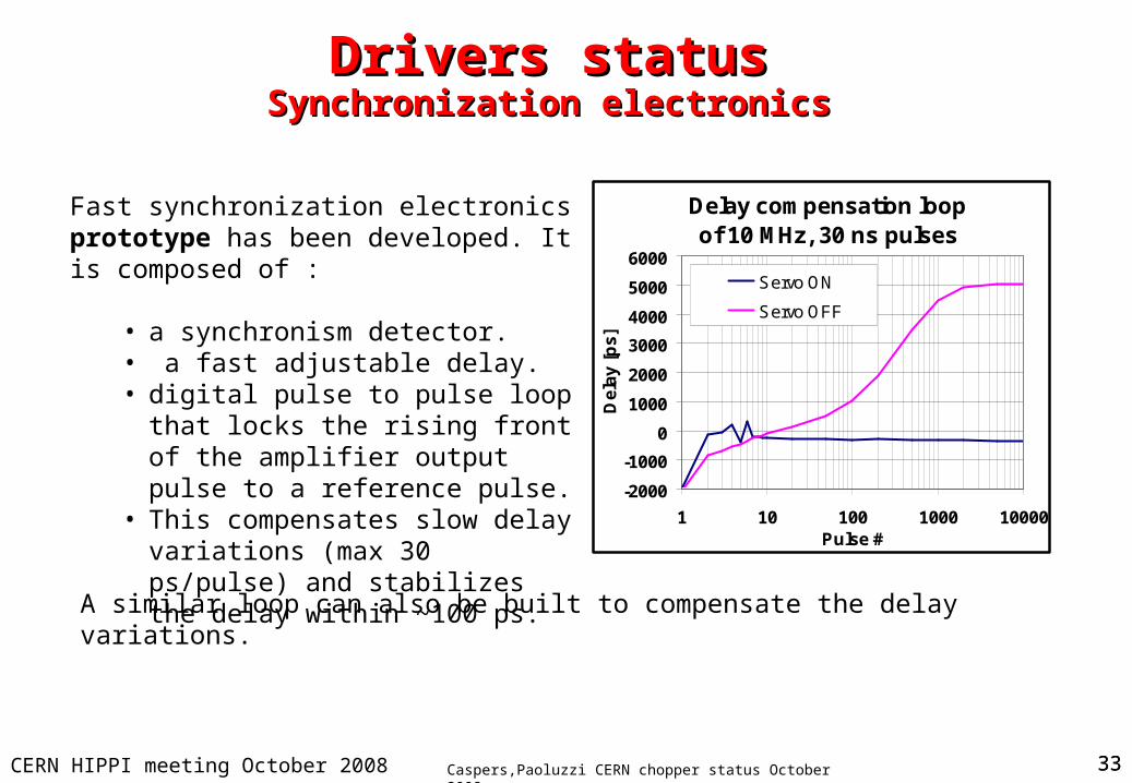
Drivers statusDrivers statusSynchronization electronicsSynchronization electronics
Delay compensation loopof 10 MHz, 30 ns pulses
-2000
-1000
0
1000
2000
3000
4000
5000
6000
1 10 100 1000 10000Pulse #
De
lay
[p
s]
Servo ON
Servo OFF
Fast synchronization electronics prototype has been developed. It is composed of :
• a synchronism detector.• a fast adjustable delay.• digital pulse to pulse loop that locks
the rising front of the amplifier output pulse to a reference pulse.
• This compensates slow delay variations (max 30 ps/pulse) and stabilizes the delay within ~100 ps.
A similar loop can also be built to compensate the delay variations.

Caspers,Paoluzzi CERN chopper status October 2008CERN HIPPI meeting October 2008 34
… … finallyfinally
The achievement of the full specifications seems to be a very complicated task and the experience gained until now is very important.
The rise and fall time are only part of the difficulties as pulse delay and pulse length distortion are also very difficult to be maintained within a fraction of ns.
Even if only partially fulfilling the specifications, 3 units of each polarity will be delivered at the end of November 2008. They will already implement some improvements.
The availability of the drivers will allow testing in 2009 the overall chopper system without beam.
The development will then continue to achieve full specs.
Caspers,Paoluzzi CERN chopper status October 2008CERN HIPPI meeting October 2008 35
AcknowledgementsAcknowledgements
We would like to thank the AB-RF workshops for assembling the tank, F. Wurster, M. Nagata and Mr U.Behrens from Kyocera for fruitful cooperation in development and implementation of the technologies for printing the meander structure
J. Borburgh for assistance with the heat transfer measurements and in particular Vladimir Bretin and his crew from the RF mechanical workshop for his infinite patience and diligence in mounting and demounting this structure.
Thanks also to R. Garoby and T. Linnecar for support


![HIPPI Test [5]ethan/comp_cray/OLNET... · HIPPI Test [5] ! #" $ % & ('*)+,- ./0 !12" 1234 15 6 15" 7 8 3434$ # 94:;](https://img.pdfslide.us/doc/110x75/5fdc1a270f88c11002682c49/hippi-test-5-ethancompcrayolnet-hippi-test-5-.jpg)