Embed Size (px)
Citation preview
Ceramics Studio
Office of Safety & Risk Management Rosalie Sharpe Pavilion 115 McCaul Room 2210
Stud
io E
quip
men
t Sa
fe O
pera
ting
Proc
edur
es

------------------------- This page intentionally left blank ---------------------------
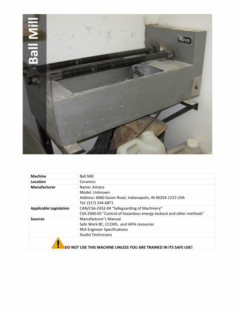
Machine Ball Mill Location Ceramics Manufacturer Name: Amaco
Model: Unknown Address: 6060 Guion Road‚ Indianapolis, IN 46254-1222 USA Tel: (317) 244-6871
Applicable Legislation
CAN/CSA-Z432-04 “Safeguarding of Machinery” CSA Z460-05 “Control of hazardous energy-lockout and other methods”
Sources
Manufacturer’s Manual Safe Work BC, CCOHS, and IAPA resources REA Engineer Specifications Studio Technicians
DO NOT USE THIS MACHINE UNLESS YOU ARE TRAINED IN ITS SAFE USE!
Ball
Mill

1.0 Personal Protective Equipment (PPE) Requirements
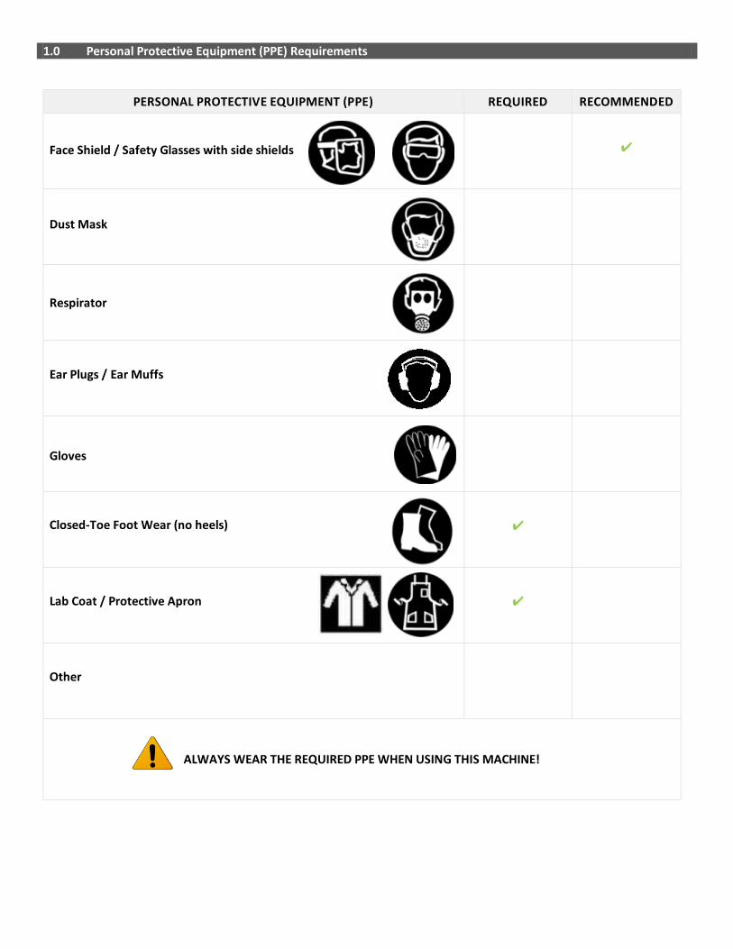
PERSONAL PROTECTIVE EQUIPMENT (PPE) REQUIRED RECOMMENDED
Face Shield / Safety Glasses with side shields ✔
Dust Mask
✔
Respirator ✔
Ear Plugs / Ear Muffs
✔
Gloves
Closed-Toe Foot Wear (no heels) ✔
Lab Coat / Protective Apron
✔
Other
ALWAYS WEAR THE REQUIRED PPE WHEN USING THIS MACHINE!
2.0 Pre-use Inspection Checklist
Check Y N N/A
1 Do you know where the emergency stop feature is located? The ball mill has an attachment plug and receptacle (plug/socket combination) and so it may be used to disable the machine in the event of an emergency.
2 Are guards in place and in good working order?
3 Is the area around the ball mill free of slip/trip hazards?
4 Is the ball mill free of defects and damage?
5 Are the friction rollers free of defects in attached securely in place?
Comments/Corrective Action:
3.0 Safe Operating Procedure (SOP)
This procedure is outlined as follows: General Safety Guidelines Equipment Specific Safety Operating Procedure
3.1 General Safety Guidelines Before using the machine, perform the following general safety checks:
• Make sure you understand all of the instructional material before operating this equipment. Failure to follow safety
instruction and warnings may result in serious personal injury, fire or property damage.
• If you have any questions or uncertainties, please ask your studio technician before use.
• Long hair, scarves, loose clothing, jewellery and ties pose an entanglement hazard. Please make sure these are all constrained prior to operating the equipment.
• Do not conduct any maintenance or repairs on this equipment. In case of a defect, contact your technician.
• Ensure you know where the emergency stops for your equipment are prior to use and within reach during
operation. In the absence of an emergency stop, ensure that the power switch is within reach.
• Do not remove or render machine guarding ineffective in any way.
• Ensure the work area is both well lit and organized.
3.2 Equipment Specific Safe Operating Procedure (SOP)
1. Before using the Buffer and Belt Sander
Pi
ctur
e 1
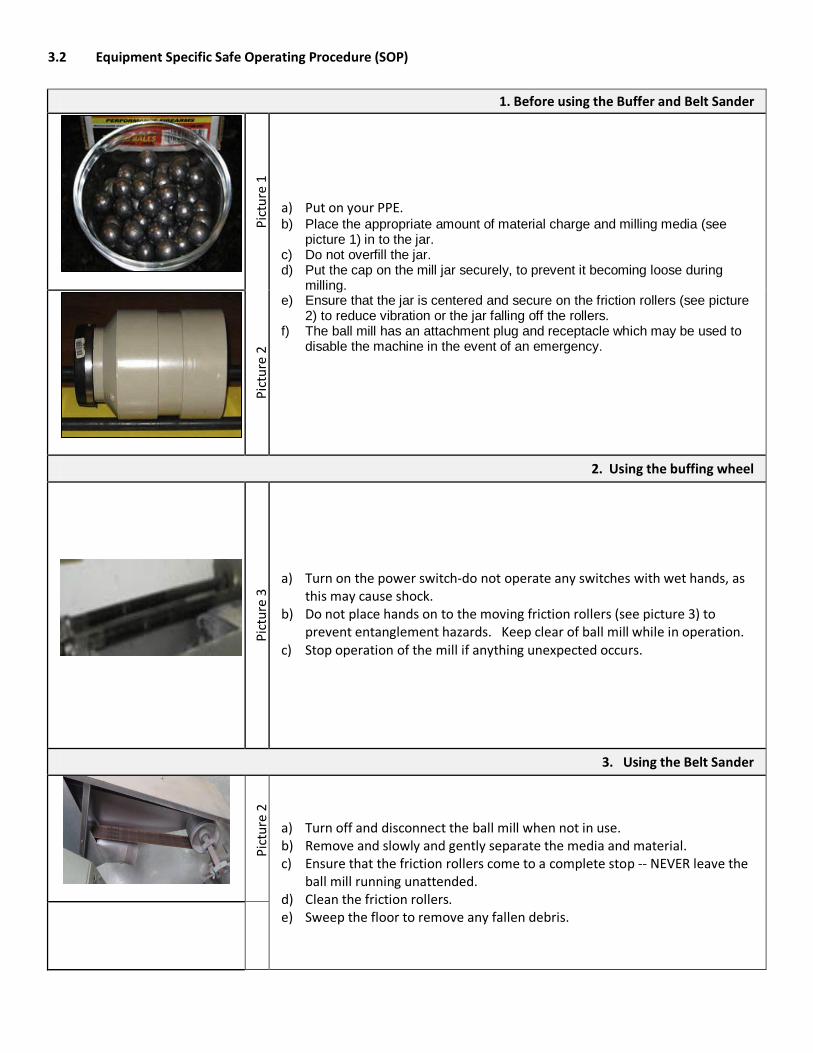
a) Put on your PPE. b) Place the appropriate amount of material charge and milling media (see
picture 1) in to the jar. c) Do not overfill the jar. d) Put the cap on the mill jar securely, to prevent it becoming loose during
milling. e) Ensure that the jar is centered and secure on the friction rollers (see picture
2) to reduce vibration or the jar falling off the rollers. f) The ball mill has an attachment plug and receptacle which may be used to
disable the machine in the event of an emergency.
Pict
ure
2
2. Using the buffing wheel
Pict
ure
3 a) Turn on the power switch-do not operate any switches with wet hands, as
this may cause shock. b) Do not place hands on to the moving friction rollers (see picture 3) to
prevent entanglement hazards. Keep clear of ball mill while in operation. c) Stop operation of the mill if anything unexpected occurs.
3. Using the Belt Sander
Pict
ure
2
a) Turn off and disconnect the ball mill when not in use. b) Remove and slowly and gently separate the media and material. c) Ensure that the friction rollers come to a complete stop -- NEVER leave the
ball mill running unattended. d) Clean the friction rollers. e) Sweep the floor to remove any fallen debris.
4.0 Maintenance and Repair
4.1. Lockout/Tagout Procedure
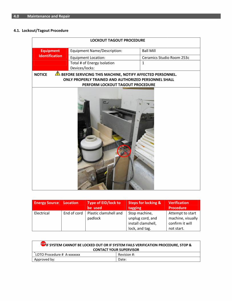
LOCKOUT TAGOUT PROCEDURE
Equipment Identification
Equipment Name/Description: Ball Mill
Equipment Location: Ceramics Studio Room 253c Total # of Energy Isolation
Devices/locks: 1
NOTICE BEFORE SERVICING THIS MACHINE, NOTIFY AFFECTED PERSONNEL. ONLY PROPERLY TRAINED AND AUTHORIZED PERSONNEL SHALL PERFORM LOCKOUT TAGOUT PROCEDURE
Energy Source Location Type of EID/lock to be used
Steps for locking & tagging
Verification Procedure
Electrical End of cord Plastic clamshell and padlock
Stop machine, unplug cord, and install clamshell, lock, and tag.
Attempt to start machine, visually confirm it will not start.
IF SYSTEM CANNOT BE LOCKED OUT OR IF SYSTEM FAILS VERIFICATION PROCEDURE, STOP & CONTACT YOUR SUPERVISOR
*LOTO Procedure # A-xxxxxxx Revision #: Approved by: Date:

4.2 Inspection Checklist
DAILY ✔ Ensure that the power cords are free of damage. Ensure guards are in place and in good working order. Ensure that the ball mill is secure and leve Ensure the area around the ball mill is free of slip/trip hazards.
Ensure that the buffing wheel is free of defects.
Ensure that the sanding belt is free of defects. WEEKLY ✔
Ensure that connections are tight. Tighten loose connections with a wrench.
MONTHLY ✔
Clean the ball mill and friction rollers. Lubricate bearings as necessary.
ANNUALLY ✔ Inspect entire machine and perform maintenance as required.

5.0 Document Control
Any changes or updates to this document must be recorded and maintained.
Initially Created By: The Office of Safety and Risk Management Date: September 2011
Consultation: Studio Managers and Technicians Program Chairs and faculty
Date: January-April 2013 April – May, 2013
Approval By: VPFA and VPA Date: September, 2013
Review and Revisions Made By: Date Revised:
Changes Made(indicate sections):
Revisions Approved By: Date of Approval:

------------------------- This page intentionally left blank ---------------------------
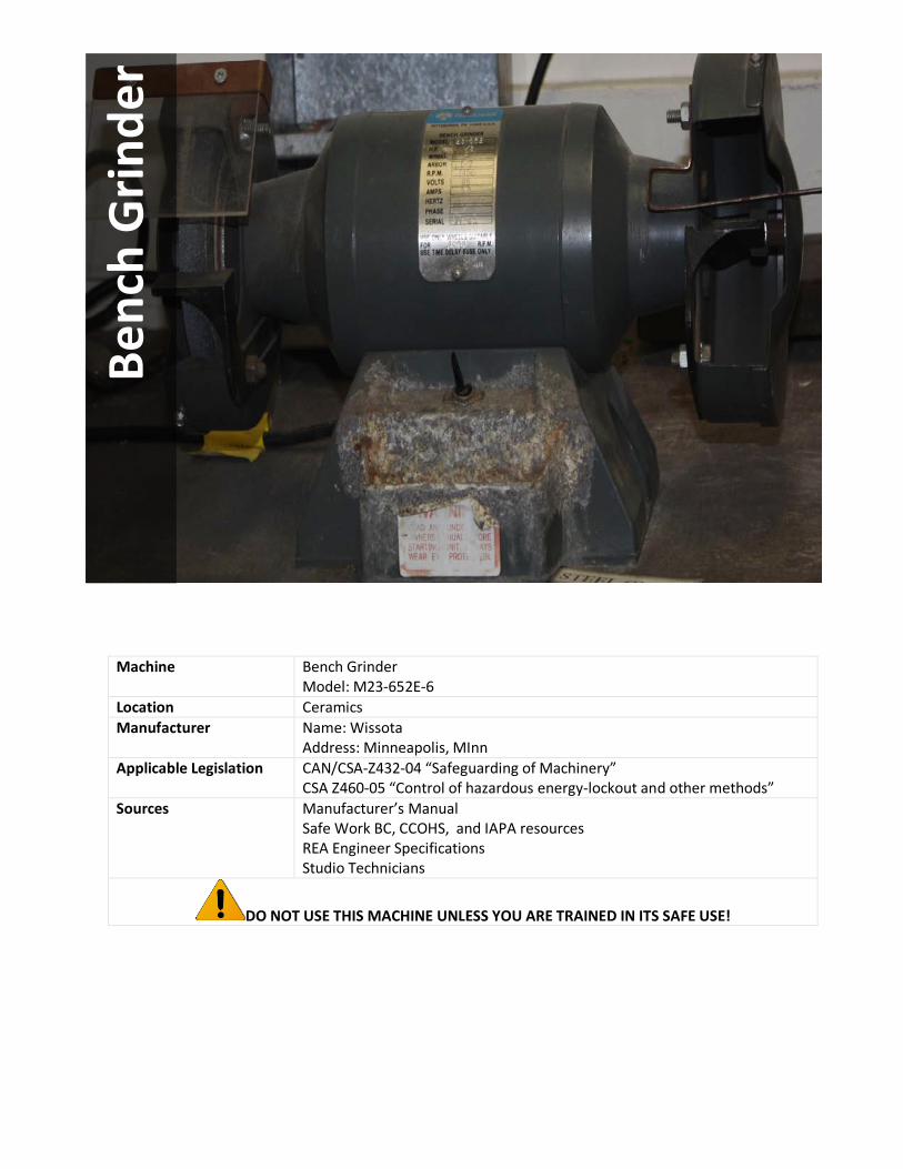
Machine Bench Grinder Model: M23-652E-6
Location Ceramics Manufacturer Name: Wissota
Address: Minneapolis, MInn Applicable Legislation
CAN/CSA-Z432-04 “Safeguarding of Machinery” CSA Z460-05 “Control of hazardous energy-lockout and other methods”
Sources
Manufacturer’s Manual Safe Work BC, CCOHS, and IAPA resources REA Engineer Specifications Studio Technicians
DO NOT USE THIS MACHINE UNLESS YOU ARE TRAINED IN ITS SAFE USE!
Benc
h G
rinde
r

1.0 Personal Protective Equipment (PPE) Requirements
PERSONAL PROTECTIVE EQUIPMENT (PPE) REQUIRED RECOMMENDED
Face Shield / Safety Glasses with side shields ✔
Dust Mask
✔
Respirator
Ear Plugs / Ear Muffs
✔
Gloves
Closed-Toe Foot Wear (no heels) ✔
Lab Coat / Protective Apron
Other
ALWAYS WEAR THE REQUIRED PPE WHEN USING THIS MACHINE!

2.0 Pre-use Inspection Checklist
Check Y N N/A
1 Are the power cords free of frays and damage?
2 Do you know where the emergency stop feature is located? The grinder has an attachment plug and receptacle (plug/socket combination) and so it may be used to disable the machine in the event of an emergency.
3 Are guards in place and in good working order?
4 Is the area around the grinder free of slip/trip hazards?
5 Has the debris/material from previous operations been removed?
6 Are the wheels free of defects? (Faults in the wheels can be very hazardous).
7 Do the wheels move freely without obstruction? Turn the wheel by hand to ensure it doesn’t touch the guard, spark deflectors or tool rests and runs freely.
8 Is the tool rest kept adjusted no greater than a 3mm gap to the grinding wheel, above the centerline of the grinding wheel?
9 Is the material you are grinding suitable for the grinder and wheel being used? Wheels are made only for grinding certain items. Do not grind rough forgings on a small precision grinding wheel.
10 Is the material the correct size for the grinder being used? (Ensure the material is not too big or too small).
11 Is there a water container nearby for cooling of the material being ground?
Comments/Corrective Action:

3.0 Safe Operating Procedure (SOP)
This procedure is outlined as follows: General Safety Guidelines Equipment Specific Safety Operating Procedure 3.1 General Safety Guidelines Before using the machine, perform the following general safety checks:
• Make sure you understand all of the instructional material before operating this equipment. Failure to follow safety
instruction and warnings may result in serious personal injury, fire or property damage.
• If you have any questions or uncertainties, please ask your studio technician before use.
• Long hair, scarves, loose clothing, jewellery and ties pose an entanglement hazard. Please make sure these are all constrained prior to operating the equipment.
• Do not conduct any maintenance or repairs on this equipment. In case of a defect, contact your technician.
• Make sure the cord is kept away from heat, oil, sharp edges or moving parts and does not pose a trip hazard.
• Ensure you know where the emergency stops for your equipment are prior to use and within reach during
operation. In the absence of an emergency stop, ensure that the power switch is within reach.
• Do not remove or render machine guarding ineffective in any way.
• Ensure the work area is both well lit and organized.
3.2 Equipment Specific Safe Operating Procedure (SOP)
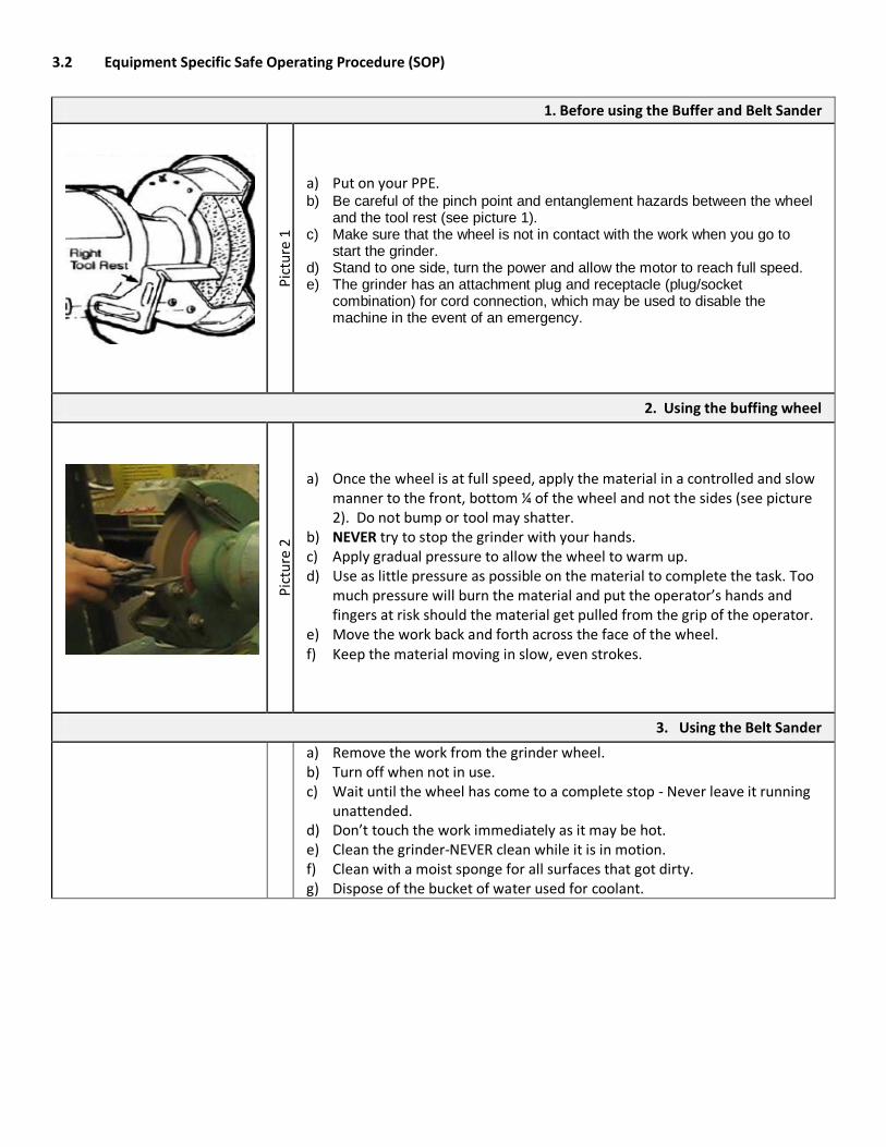
1. Before using the Buffer and Belt Sander
Pict
ure
1
a) Put on your PPE. b) Be careful of the pinch point and entanglement hazards between the wheel
and the tool rest (see picture 1). c) Make sure that the wheel is not in contact with the work when you go to
start the grinder. d) Stand to one side, turn the power and allow the motor to reach full speed. e) The grinder has an attachment plug and receptacle (plug/socket
combination) for cord connection, which may be used to disable the machine in the event of an emergency.
2. Using the buffing wheel
Pict
ure
2
a) Once the wheel is at full speed, apply the material in a controlled and slow manner to the front, bottom ¼ of the wheel and not the sides (see picture 2). Do not bump or tool may shatter.
b) NEVER try to stop the grinder with your hands. c) Apply gradual pressure to allow the wheel to warm up. d) Use as little pressure as possible on the material to complete the task. Too
much pressure will burn the material and put the operator’s hands and fingers at risk should the material get pulled from the grip of the operator.
e) Move the work back and forth across the face of the wheel. f) Keep the material moving in slow, even strokes.
3. Using the Belt Sander
a) Remove the work from the grinder wheel. b) Turn off when not in use. c) Wait until the wheel has come to a complete stop - Never leave it running
unattended. d) Don’t touch the work immediately as it may be hot. e) Clean the grinder-NEVER clean while it is in motion. f) Clean with a moist sponge for all surfaces that got dirty. g) Dispose of the bucket of water used for coolant.
4.0 Maintenance and Repair
4.1. Lockout/Tagout Procedure
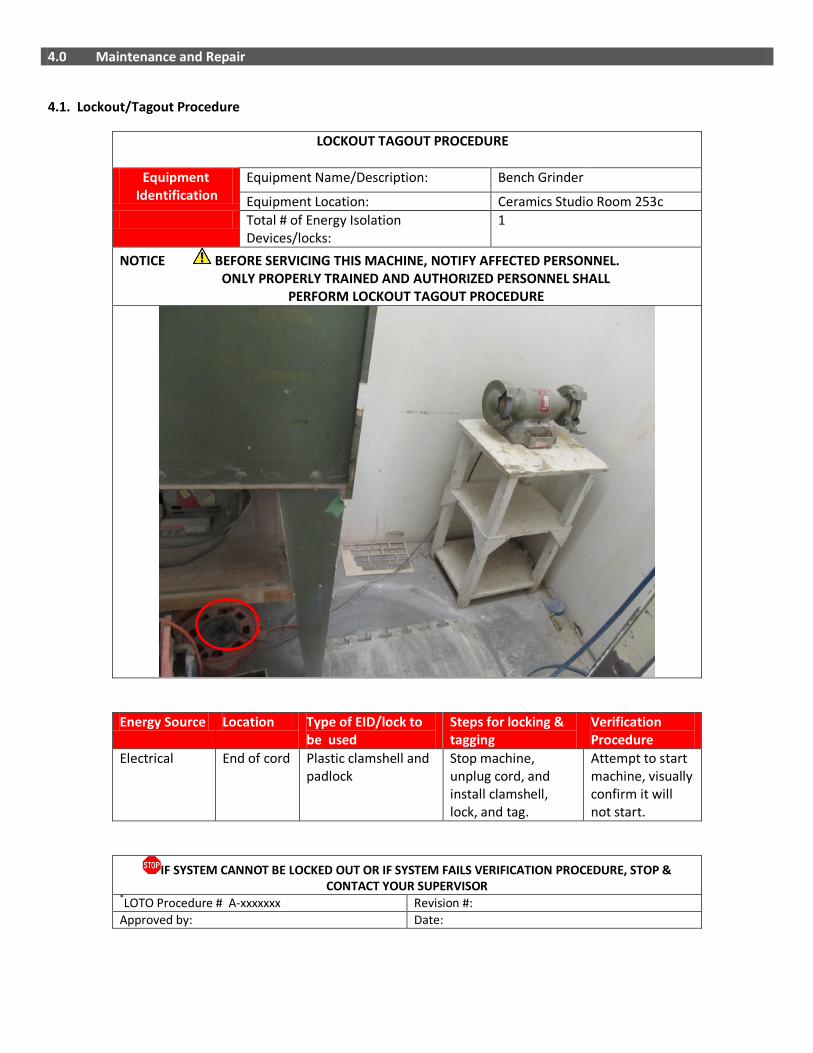
LOCKOUT TAGOUT PROCEDURE
Equipment Identification
Equipment Name/Description: Bench Grinder
Equipment Location: Ceramics Studio Room 253c Total # of Energy Isolation
Devices/locks: 1
NOTICE BEFORE SERVICING THIS MACHINE, NOTIFY AFFECTED PERSONNEL. ONLY PROPERLY TRAINED AND AUTHORIZED PERSONNEL SHALL PERFORM LOCKOUT TAGOUT PROCEDURE
Energy Source Location Type of EID/lock to be used
Steps for locking & tagging
Verification Procedure
Electrical End of cord Plastic clamshell and padlock
Stop machine, unplug cord, and install clamshell, lock, and tag.
Attempt to start machine, visually confirm it will not start.
IF SYSTEM CANNOT BE LOCKED OUT OR IF SYSTEM FAILS VERIFICATION PROCEDURE, STOP & CONTACT YOUR SUPERVISOR
*LOTO Procedure # A-xxxxxxx Revision #: Approved by: Date:

4.2 Inspection Checklist
DAILY ✔ Ensure that the power cords are free of damage. Ensure guards are in place and in good working order. Ensure that the grinder is secure and level Ensure the area around the grinder is free of slip/trip hazards.
Ensure that debris/material from previous operations has been removed.
Ensure that the wheels are free of defects (tears in the wheels can be very hazardous as they can propel debris towards the operator).
Ensure that the wheels move freely without obstruction.
WEEKLY ✔
Ensure that the adjustable tongue guard is kept to within 1/4-inch of the wheel.
Ensure that the work rest is kept to within 1/16-inch of the wheel.
Ensure that the spark breaker is kept within 1/16-inch of the wheel.
Dress wheels-frequent, light dressings rather than one heavy dressing.
MONTHLY ✔
Ensure that wheels have blotters on each side.
Ensure that the wheels fit and don’t vibrate. If loose, get another wheel.
Ensure that the wheels are free of defects. If replacing, inspect wheels before mounting. Don’t use a wheel that was dropped or doesn’t fit properly. Don’t use excessive force to tighten wheels. Test run a new wheel before use.
ANNUALLY ✔
Check that all nuts, bolts, screws and other fixings are properly tightened-don’t over tighten wheel nuts.
Ensure that tool rest and spark breakers are adjusted correctly.
Inspect entire machine and perform maintenance as required.

5.0 Document Control
Any changes or updates to this document must be recorded and maintained.
Initially Created By: The Office of Safety and Risk Management Date: September 2011
Consultation: Studio Managers and Technicians Program Chairs and faculty
Date: January-April 2013 April – May, 2013
Approval By: VPFA and VPA Date: September, 2013
Review and Revisions Made By: Date Revised:
Changes Made(indicate sections):
Revisions Approved By: Date of Approval:

------------------------- This page intentionally left blank ---------------------------
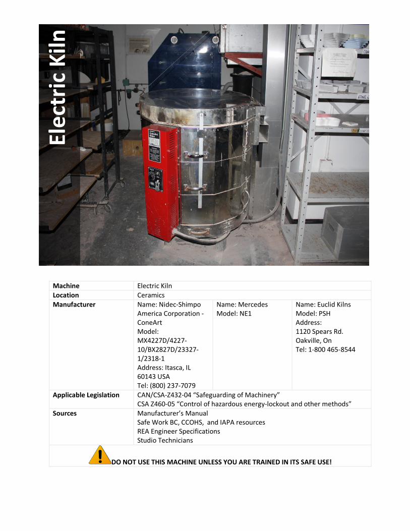
Machine Electric Kiln Location Ceramics Manufacturer Name: Nidec-Shimpo
America Corporation -ConeArt Model: MX4227D/4227-10/BX2827D/23327-1/2318-1 Address: Itasca, IL 60143 USA Tel: (800) 237-7079
Name: Mercedes Model: NE1
Name: Euclid Kilns Model: PSH Address: 1120 Spears Rd. Oakville, On Tel: 1-800 465-8544
Applicable Legislation
CAN/CSA-Z432-04 “Safeguarding of Machinery” CSA Z460-05 “Control of hazardous energy-lockout and other methods”
Sources
Manufacturer’s Manual Safe Work BC, CCOHS, and IAPA resources REA Engineer Specifications Studio Technicians
DO NOT USE THIS MACHINE UNLESS YOU ARE TRAINED IN ITS SAFE USE!
Elec
tric
Kiln

1.0 Personal Protective Equipment (PPE) Requirements
PERSONAL PROTECTIVE EQUIPMENT (PPE) REQUIRED RECOMMENDED
Face Shield / Safety Glasses with side shields ✔
Dust Mask
✔
Respirator
Ear Plugs / Ear Muffs
Gloves ✔
Closed-Toe Foot Wear (no heels) ✔
Lab Coat / Protective Apron
✔
Other
ALWAYS WEAR THE REQUIRED PPE WHEN USING THIS MACHINE!
2.0 Pre-use Inspection Checklist
Check Y N N/A
1 Is the area around the kiln free of slip/trip hazards and kept dry? (Do not stand in moisture while operating the kiln).
2 Are flammable/combustible materials (e.g. paper, plastic) removed from the immediate area?
3 Has the debris/material from previous operations been removed?
Are the kiln, lid and floor bricks free from large defects/cracks?
4 Is the kiln clean? Remove contaminants if necessary.
5 Is the lid closing properly?
6 Is the lid brace connected securely to the kiln and kiln lid?
7 Is the ware bone dry? (firing damp ware can result in the loss of ware or kiln damage by explosion from rapidly escaping steam).
8 Are you using witness cones? Never fire the kiln without witness cones (even if your kiln is equipped with an automatic controller or kiln sitter) as they virtually eliminate the risk of over-firing by measuring the amount of heat absorbed and the also confirm the proper functioning of the firing and instrumentation. Place them so that they are visible through the peepholes, at an 8° angle from vertical in a cone holder.
9 Is there adequate ventilation?
Comments/Corrective Action:
3.0 Safe Operating Procedure (SOP)
This procedure is outlined as follows: General Safety Guidelines Equipment Specific Safety Operating Procedure 3.1 General Safety Guidelines Before using the machine, perform the following general safety checks:
• Make sure you understand all of the instructional material before operating this equipment. Failure to follow safety
instruction and warnings may result in serious personal injury, fire or property damage.
• If you have any questions or uncertainties, please ask your studio technician before use.
• Long hair, scarves, loose clothing, jewellery and ties pose an entanglement hazard. Please make sure these are all constrained prior to operating the equipment.
• Do not conduct any maintenance or repairs on this equipment. In case of a defect, contact your technician.
• Do not remove or render machine guarding ineffective in any way.
• Ensure the work area is both well lit and organized.
3.2 Equipment Specific Safe Operating Procedure (SOP)
1. Before using the Kiln
Pi
ctur
e 1
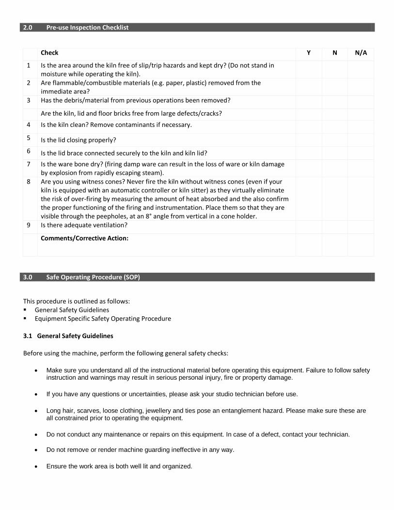
a) Put on your PPE. CAUTION: The kiln produces extreme heat. b) For every firing, place three witness cones (see picture 1) 3" behind each
peephole and on every kiln shelf (these indicate if the kiln is firing evenly and confirms the proper functioning of kiln instrumentation (e.g. kiln sitter).
2. Loading the Kiln
Pict
ure
2
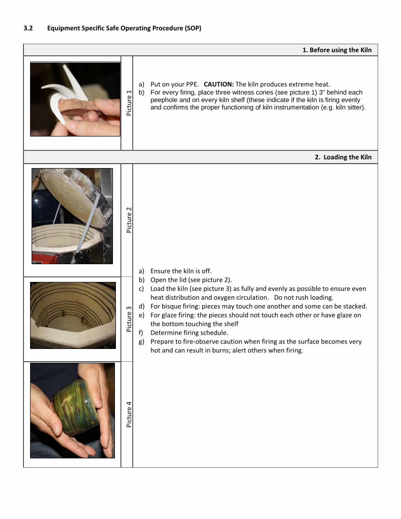
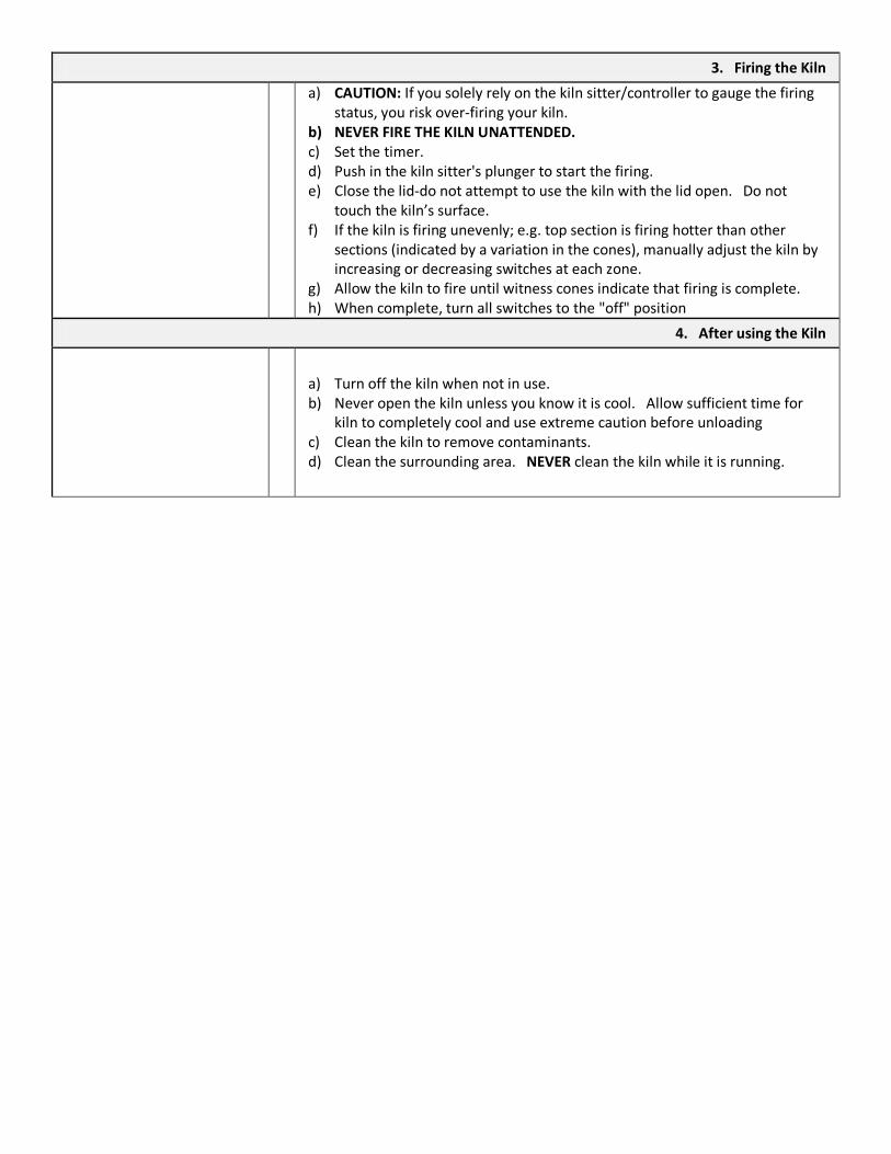
a) Ensure the kiln is off. b) Open the lid (see picture 2). c) Load the kiln (see picture 3) as fully and evenly as possible to ensure even
heat distribution and oxygen circulation. Do not rush loading. d) For bisque firing: pieces may touch one another and some can be stacked. e) For glaze firing: the pieces should not touch each other or have glaze on
the bottom touching the shelf f) Determine firing schedule. g) Prepare to fire-observe caution when firing as the surface becomes very
hot and can result in burns; alert others when firing.
Pict
ure
3
Pict
ure
4
3. Firing the Kiln
a) CAUTION: If you solely rely on the kiln sitter/controller to gauge the firing status, you risk over-firing your kiln.
b) NEVER FIRE THE KILN UNATTENDED. c) Set the timer. d) Push in the kiln sitter's plunger to start the firing. e) Close the lid-do not attempt to use the kiln with the lid open. Do not
touch the kiln’s surface. f) If the kiln is firing unevenly; e.g. top section is firing hotter than other
sections (indicated by a variation in the cones), manually adjust the kiln by increasing or decreasing switches at each zone.
g) Allow the kiln to fire until witness cones indicate that firing is complete. h) When complete, turn all switches to the "off" position
4. After using the Kiln
a) Turn off the kiln when not in use. b) Never open the kiln unless you know it is cool. Allow sufficient time for
kiln to completely cool and use extreme caution before unloading c) Clean the kiln to remove contaminants. d) Clean the surrounding area. NEVER clean the kiln while it is running.
4.0 Maintenance and Repair
4.1. Lockout/Tagout Procedure
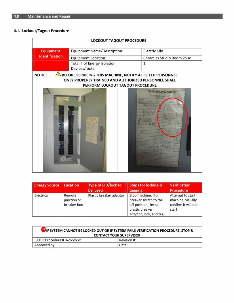
LOCKOUT TAGOUT PROCEDURE
Equipment Identification
Equipment Name/Description: Electric Kiln
Equipment Location: Ceramics Studio Room 253c Total # of Energy Isolation
Devices/locks: 1
NOTICE BEFORE SERVICING THIS MACHINE, NOTIFY AFFECTED PERSONNEL. ONLY PROPERLY TRAINED AND AUTHORIZED PERSONNEL SHALL PERFORM LOCKOUT TAGOUT PROCEDURE
Energy Source Location Type of EID/lock to be used
Steps for locking & tagging
Verification Procedure
Electrical Remote junction or breaker box
Plastic breaker adaptor Stop machine, flip breaker switch to the off position, install plastic breaker adaptor, lock, and tag.
Attempt to start machine, visually confirm it will not start.
IF SYSTEM CANNOT BE LOCKED OUT OR IF SYSTEM FAILS VERIFICATION PROCEDURE, STOP & CONTACT YOUR SUPERVISOR
*LOTO Procedure # A-xxxxxxx Revision #: Approved by: Date:

4.2 Inspection Checklist
DAILY ✔ Ensure that power cords are free of frays and damage and positioned so that they do not touch the side of the kiln.
Ensure that the kiln is secure with a level stand that does not teeter-an uneven stand is a safety hazard and may put stress in the kiln during firing (if stand is not level, place firm shims under the kiln stand legs until stand is level).
Ensure that the area around the kiln is free of slip/trip hazards and kept dry and free of moisture.
Are flammable/combustible materials (e.g. paper, plastic) removed from the immediate area?
Ensure that the kiln, lid and floor bricks are free of large defects/cracks.(hairline cracks are ok). Ensure that the lid is in good condition and closing properly. Ensure that the lid brace is connected securely to the kiln and kiln lid. Ensure that the latches (that lock sections together) are securely fastened. Ensure that elements are not popping out of the grooves (careful, elements are very brittle when cold). To repair: heat the element until it is glowing orange; shut off and disconnect kiln. With a metal instrument, carefully push the element back into place and pin. Fire the kiln hotter than normal once in a while if the elements pop out regularly.
Ensure that the sensing rod of the Dawson Kiln Sitter® moves freely in the tube assembly, free from wear and properly calibrated (use the firing gauge to check the sitter's adjustment). Replace if they start to corrode or warp.
If your kiln is equipped with a Bartlett V6-CF™ automatic controller, check the thermocouples and replace them if they appear thin/corroded; if it breaks during a firing, the safety system will automatically shut off the kiln, resulting in an interrupted firing and potential ware damage.
Ensure that there are ware, witness cones and cone holders available. Ensure that there is adequate ventilation. WEEKLY ✔
Confirm that firing gauge is properly calibrated.
MONTHLY ✔ Check elements for aging or need of replacement. Vacuum element grooves.
Due to the expansion and contraction of heating, the electrical connections inside the switch panel may loosen; ensure that they are tight
Ensure that the lid is free from brick particles; remove glaze spots from bricks.
Wipe shelves clean, and apply kiln wash ONLY to the TOP of the shelves (to protect against glaze drips); NEVER APPLY KILN WASH TO THE LID/WALLS.
Shelves may need a new layer of kiln wash; occasionally old kiln wash must be completely removed with a scraper and wire brush and a new layer of kiln wash evenly re-applied.
ANNUALLY ✔
Inspect entire machine and perform maintenance as required.

5.0 Document Control
Any changes or updates to this document must be recorded and maintained.
Initially Created By: The Office of Safety and Risk Management Date: September 2011
Consultation: Studio Managers and Technicians Program Chairs and faculty
Date: January-April 2013 April – May, 2013
Approval By: VPFA and VPA Date: September, 2013
Review and Revisions Made By: Date Revised:
Changes Made(indicate sections):
Revisions Approved By: Date of Approval:

------------------------- This page intentionally left blank ---------------------------

Machine Jigger Jolly Model: M Jigger
Location Ceramics Manufacturer Name: Ratcliffe
Address: Unit 5 Brookside Business Park, STONE, UK, ST15 0RZ Tel: Unknown
Applicable Legislation
CAN/CSA-Z432-04 “Safeguarding of Machinery” CSA Z460-05 “Control of hazardous energy-lockout and other methods”
Sources
Manufacturer’s Manual Safe Work BC, CCOHS, and IAPA resources REA Engineer Specifications Studio Technicians
DO NOT USE THIS MACHINE UNLESS YOU ARE TRAINED IN ITS SAFE USE!
Jigge
r Jol
ly

1.0 Personal Protective Equipment (PPE) Requirements
PERSONAL PROTECTIVE EQUIPMENT (PPE) REQUIRED RECOMMENDED
Face Shield / Safety Glasses with side shields ✔
Dust Mask
Respirator
Ear Plugs / Ear Muffs
Gloves
Closed-Toe Foot Wear (no heels) ✔
Lab Coat / Protective Apron
✔
Other
ALWAYS WEAR THE REQUIRED PPE WHEN USING THIS MACHINE!

2.0 Pre-use Inspection Checklist
Check Y N N/A
1 Are the power cords free of frays and damage?
2 Do you know where the emergency stop feature is located? The jigger joly has an attachment plug and receptacle (plug/socket combination) and so it may be used to disable the machine in the event of an emergency.
3 Are guards in place and in good working order?
4 Is the area around the machine free of slip/trip hazards?
5 Has the debris/material from previous operations been removed?
6 Is the Jigger Jolly secure and level to reduce vibration and movement, which could result in injury?
7 Is the Jigger Jolly free of defects and damage?
8 Is the arm and tool used to form the clay free from defects, damage, grease/oil and kept dry?
9 Is the outside profile mold securely in place, in good condition and without defects?
10 Are you using an acceptable amount of clay, without overloading the jigger jolly?
Comments/Corrective Action:

3.0 Safe Operating Procedure (SOP)
This procedure is outlined as follows: General Safety Guidelines Equipment Specific Safety Operating Procedure 3.1 General Safety Guidelines Before using the machine, perform the following general safety checks:
• Make sure you understand all of the instructional material before operating this equipment. Failure to follow safety
instruction and warnings may result in serious personal injury, fire or property damage.
• If you have any questions or uncertainties, please ask your studio technician before use.
• Long hair, scarves, loose clothing, jewellery and ties pose an entanglement hazard. Please make sure these are all constrained prior to operating the equipment.
• Do not conduct any maintenance or repairs on this equipment. In case of a defect, contact your technician.
• Make sure the cord is kept away from heat, oil, sharp edges or moving parts and does not pose a trip hazard.
• Ensure you know where the emergency stops for your equipment are prior to use and within reach during
operation. In the absence of an emergency stop, ensure that the power switch is within reach.
• Do not remove or render machine guarding ineffective in any way.
• Ensure the work area is both well lit and organized.
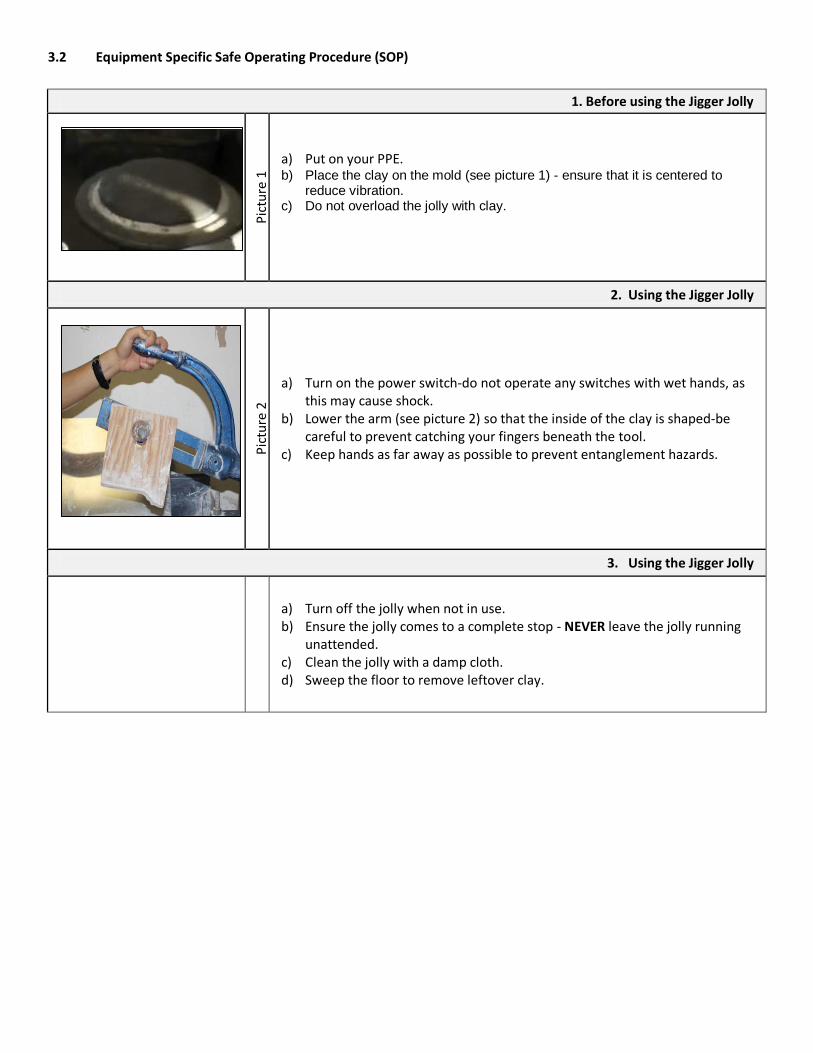
3.2 Equipment Specific Safe Operating Procedure (SOP)
1. Before using the Jigger Jolly
Pi
ctur
e 1
a) Put on your PPE. b) Place the clay on the mold (see picture 1) - ensure that it is centered to
reduce vibration. c) Do not overload the jolly with clay.
2. Using the Jigger Jolly
Pict
ure
2
a) Turn on the power switch-do not operate any switches with wet hands, as this may cause shock.
b) Lower the arm (see picture 2) so that the inside of the clay is shaped-be careful to prevent catching your fingers beneath the tool.
c) Keep hands as far away as possible to prevent entanglement hazards.
3. Using the Jigger Jolly
a) Turn off the jolly when not in use. b) Ensure the jolly comes to a complete stop - NEVER leave the jolly running
unattended. c) Clean the jolly with a damp cloth. d) Sweep the floor to remove leftover clay.
4.0 Maintenance and Repair
4.1. Lockout/Tagout Procedure
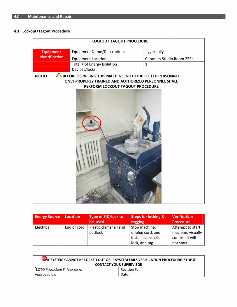
LOCKOUT TAGOUT PROCEDURE
Equipment Identification
Equipment Name/Description: Jigger Jolly
Equipment Location: Ceramics Studio Room 253c Total # of Energy Isolation
Devices/locks: 1
NOTICE BEFORE SERVICING THIS MACHINE, NOTIFY AFFECTED PERSONNEL. ONLY PROPERLY TRAINED AND AUTHORIZED PERSONNEL SHALL PERFORM LOCKOUT TAGOUT PROCEDURE
Energy Source Location Type of EID/lock to be used
Steps for locking & tagging
Verification Procedure
Electrical End of cord Plastic clamshell and padlock
Stop machine, unplug cord, and install clamshell, lock, and tag.
Attempt to start machine, visually confirm it will not start.
IF SYSTEM CANNOT BE LOCKED OUT OR IF SYSTEM FAILS VERIFICATION PROCEDURE, STOP & CONTACT YOUR SUPERVISOR
*LOTO Procedure # A-xxxxxxx Revision #: Approved by: Date:

4.2 Inspection Checklist
5.0 Document Control
Any changes or updates to this document must be recorded and maintained.
Initially Created By: The Office of Safety and Risk Management Date: September 2011
Consultation: Studio Managers and Technicians Program Chairs and faculty
Date: January-April 2013 April – May, 2013
Approval By: VPFA and VPA Date: September, 2013
Review and Revisions Made By: Date Revised:
Changes Made(indicate sections):
Revisions Approved By: Date of Approval:
DAILY ✔ Ensure that the power cords are free of frays and damage. Ensure that guards are in place and in good working order. Ensure that the Jolly is secure and level. Ensure that the area around the Jolly is free of slip/trip hazards. Ensure no flammable/combustible materials (i.e. paper) and degreasing, cleaning and spraying operations are in the immediate work area.
Ensure that the Jigger Jolly is free of defects and damage. Ensure that the arm and tool used to form the clay is free of defects, damage, grease, oil and kept dry. Ensure that the profile mold securely in place, in good condition and without defects.
WEEKLY ✔
Ensure that connections are tight. Tighten loose connections with a wrench.
MONTHLY ✔
Clean the jolly with a damp sponge or cloth.
ANNUALLY ✔
Inspect entire machine and perform maintenance as required.

------------------------- This page intentionally left blank ---------------------------
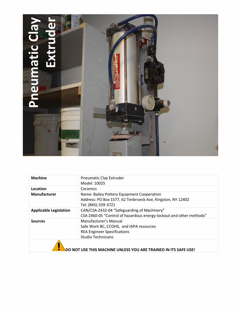
Machine Pneumatic Clay Extruder Model: 10025
Location Ceramics Manufacturer Name: Bailey Pottery Equipment Cooperation
Address: PO Box 1577, 62 Tenbroeck Ave, Kingston, NY 12402 Tel: (845)-339-3721
Applicable Legislation
CAN/CSA-Z432-04 “Safeguarding of Machinery” CSA Z460-05 “Control of hazardous energy-lockout and other methods”
Sources
Manufacturer’s Manual Safe Work BC, CCOHS, and IAPA resources REA Engineer Specifications Studio Technicians
DO NOT USE THIS MACHINE UNLESS YOU ARE TRAINED IN ITS SAFE USE!
Pneu
mat
ic C
lay
Extr
uder

1.0 Personal Protective Equipment (PPE) Requirements
PERSONAL PROTECTIVE EQUIPMENT (PPE) REQUIRED RECOMMENDED
Face Shield / Safety Glasses with side shields ✔
Dust Mask
Respirator
Ear Plugs / Ear Muffs
✔
Gloves
Closed-Toe Foot Wear (no heels) ✔
Lab Coat / Protective Apron
Other
ALWAYS WEAR THE REQUIRED PPE WHEN USING THIS MACHINE!

2.0 Pre-use Inspection Checklist
Check Y N N/A
1 Are the power cords free of frays and damage?
2 Do you know where the emergency stop feature is located? The machine has an attachment plug and receptacle (plug/socket combination) and so it may be used to disable the machine in the event of an emergency.
3 Are guards in place and in good working order?
4 Is the area around the machine free of slip/trip hazards?
5 Has the debris/material from previous operations been removed?
6 Is the extruder secure and level?
7 Is the extruder free of defects, wear and cracks?
8 Are the plunger and chute aligned?
9 Is the foot pedal cable connected?
10 Is the foot pedal level, with nothing beneath it or obstructing it?
11 Is the foot pedal free of defects/damage or debris?
12 Are wires and cables kept away from the extruding system?
13 Are you using an acceptable amount of clay?
Comments/Corrective Action:

3.0 Safe Operating Procedure (SOP)
This procedure is outlined as follows: General Safety Guidelines Equipment Specific Safety Operating Procedure 3.1 General Safety Guidelines Before using the machine, perform the following general safety checks:
• Make sure you understand all of the instructional material before operating this equipment. Failure to follow safety
instruction and warnings may result in serious personal injury, fire or property damage.
• If you have any questions or uncertainties, please ask your studio technician before use.
• Long hair, scarves, loose clothing, jewellery and ties pose an entanglement hazard. Please make sure these are all constrained prior to operating the equipment.
• Do not conduct any maintenance or repairs on this equipment. In case of a defect, contact your technician.
• Make sure the cord is kept away from heat, oil, sharp edges or moving parts and does not pose a trip hazard.
• Ensure you know where the emergency stops for your equipment are prior to use and within reach during
operation. In the absence of an emergency stop, ensure that the power switch is within reach.
• Do not remove or render machine guarding ineffective in any way.
• Ensure the work area is both well lit and organized.
3.2 Equipment Specific Safe Operating Procedure (SOP)
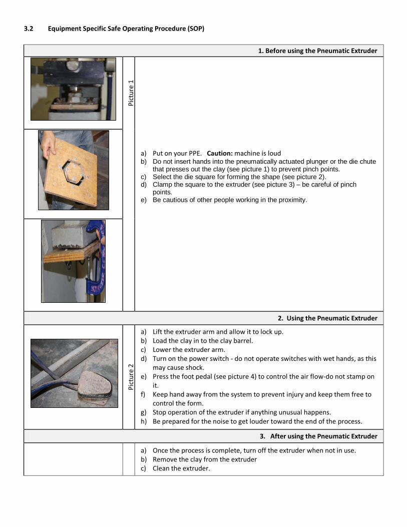
1. Before using the Pneumatic Extruder
Pict
ure
1
a) Put on your PPE. Caution: machine is loud b) Do not insert hands into the pneumatically actuated plunger or the die chute
that presses out the clay (see picture 1) to prevent pinch points. c) Select the die square for forming the shape (see picture 2). d) Clamp the square to the extruder (see picture 3) – be careful of pinch
points. e) Be cautious of other people working in the proximity.
2. Using the Pneumatic Extruder
Pict
ure
2
a) Lift the extruder arm and allow it to lock up. b) Load the clay in to the clay barrel. c) Lower the extruder arm. d) Turn on the power switch - do not operate switches with wet hands, as this
may cause shock. e) Press the foot pedal (see picture 4) to control the air flow-do not stamp on
it. f) Keep hand away from the system to prevent injury and keep them free to
control the form. g) Stop operation of the extruder if anything unusual happens. h) Be prepared for the noise to get louder toward the end of the process.
3. After using the Pneumatic Extruder
a) Once the process is complete, turn off the extruder when not in use. b) Remove the clay from the extruder c) Clean the extruder.
4.0 Maintenance and Repair
4.1. Lockout/Tagout Procedure
LOCKOUT TAGOUT PROCEDURE
Equipment Identification
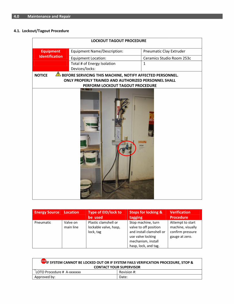
Equipment Name/Description: Pneumatic Clay Extruder
Equipment Location: Ceramics Studio Room 253c Total # of Energy Isolation
Devices/locks: 1
NOTICE BEFORE SERVICING THIS MACHINE, NOTIFY AFFECTED PERSONNEL. ONLY PROPERLY TRAINED AND AUTHORIZED PERSONNEL SHALL PERFORM LOCKOUT TAGOUT PROCEDURE
Energy Source Location Type of EID/lock to be used
Steps for locking & tagging
Verification Procedure
Pneumatic Valve on main line
Plastic clamshell or lockable valve, hasp, lock, tag
Stop machine, turn valve to off position and install clamshell or use valve locking mechanism, install hasp, lock, and tag.
Attempt to start machine, visually confirm pressure gauge at zero.
IF SYSTEM CANNOT BE LOCKED OUT OR IF SYSTEM FAILS VERIFICATION PROCEDURE, STOP & CONTACT YOUR SUPERVISOR
*LOTO Procedure # A-xxxxxxx Revision #: Approved by: Date:
4.2 Inspection Checklist
5.0 Document Control
Any changes or updates to this document must be recorded and maintained.
Initially Created By: The Office of Safety and Risk Management Date: September 2011
Consultation: Studio Managers and Technicians Program Chairs and faculty
Date: January-April 2013 April – May, 2013
Approval By: VPFA and VPA Date: September, 2013
Review and Revisions Made By: Date Revised:
Changes Made(indicate sections):
Revisions Approved By: Date of Approval:
DAILY ✔ Ensure that the power cords are free of damage. Ensure guards are in place and in good working order. Ensure that the machine is secure and level Ensure the area around the machine is free of slip/trip hazards.
Ensure that debris/material from previous operations has been removed.
Ensure that the extruder is free of defects, wear and cracks.
Ensure that the plunger and chute are aligned.
Ensure that the foot pedal cable is connected.
Ensure that the foot pedal is level, with nothing beneath it or obstructing it.
Ensure that the foot pedal is free of defects/damage or debris.
Ensure that the lever is in good condition and free of grease/oil.
Ensure that wires and cables are kept away from the extruding system.
WEEKLY ✔
Ensure that connections are tight. Tighten loose connections with a wrench.
MONTHLY ✔
Clean the extruder with a damp sponge or cloth - do not pour water onto the extruder.
ANNUALLY ✔
Inspect entire machine and perform maintenance as required.

------------------------- This page intentionally left blank ---------------------------
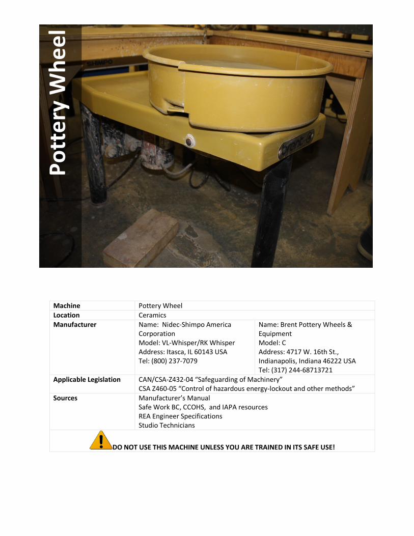
Machine Pottery Wheel Location Ceramics Manufacturer Name: Nidec-Shimpo America
Corporation Model: VL-Whisper/RK Whisper Address: Itasca, IL 60143 USA Tel: (800) 237-7079
Name: Brent Pottery Wheels & Equipment Model: C Address: 4717 W. 16th St., Indianapolis, Indiana 46222 USA Tel: (317) 244-68713721
Applicable Legislation
CAN/CSA-Z432-04 “Safeguarding of Machinery” CSA Z460-05 “Control of hazardous energy-lockout and other methods”
Sources
Manufacturer’s Manual Safe Work BC, CCOHS, and IAPA resources REA Engineer Specifications Studio Technicians
DO NOT USE THIS MACHINE UNLESS YOU ARE TRAINED IN ITS SAFE USE!
Pott
ery
Whe
el
1.0 Personal Protective Equipment (PPE) Requirements
PERSONAL PROTECTIVE EQUIPMENT (PPE) REQUIRED RECOMMENDED
Face Shield / Safety Glasses with side shields ✔
Dust Mask
Respirator
Ear Plugs / Ear Muffs
Gloves
Closed-Toe Foot Wear (no heels) ✔
Lab Coat / Protective Apron
✔
Other
ALWAYS WEAR THE REQUIRED PPE WHEN USING THIS MACHINE!

2.0 Pre-use Inspection Checklist
Check Y N N/A
1 Are the power cords free of frays and damage?
2 Do you know where the emergency stop feature is located? The machine has an attachment plug and receptacle (plug/socket combination) and so it may be used to disable the machine in the event of an emergency.
3 Is the area around the machine free of slip/trip hazards?
4 Has the debris/material from previous operations been removed?
5 Has the debris/material from previous operations been removed?
6 Is the pottery wheel secure, level and balanced to reduce vibration and movement, which could result in injury?
7 Is the pottery wheel free of defects, wear and cracks?
8 Is the splash pan in place, without defects/damage?
9 Is the foot pedal cable connected?
10 Are you using an acceptable amount of clay? A very large amount of clay may overload the wheel-the safety sensor for overload on the wheel indicates this.
11 Is the foot pedal free of defects/damage or debris?
12 Are wires and cables kept away from the wheel?
Comments/Corrective Action:

3.0 Safe Operating Procedure (SOP)
This procedure is outlined as follows: General Safety Guidelines Equipment Specific Safety Operating Procedure 3.1 General Safety Guidelines Before using the machine, perform the following general safety checks:
• Make sure you understand all of the instructional material before operating this equipment. Failure to follow safety
instruction and warnings may result in serious personal injury, fire or property damage.
• If you have any questions or uncertainties, please ask your studio technician before use.
• Long hair, scarves, loose clothing, jewellery and ties pose an entanglement hazard. Please make sure these are all constrained prior to operating the equipment.
• Do not conduct any maintenance or repairs on this equipment. In case of a defect, contact your technician.
• Make sure the cord is kept away from heat, oil, sharp edges or moving parts and does not pose a trip hazard.
• Ensure you know where the emergency stops for your equipment are prior to use and within reach during
operation. In the absence of an emergency stop, ensure that the power switch is within reach.
• Do not remove or render machine guarding ineffective in any way.
• Ensure the work area is both well lit and organized.
3.2 Equipment Specific Safe Operating Procedure (SOP)
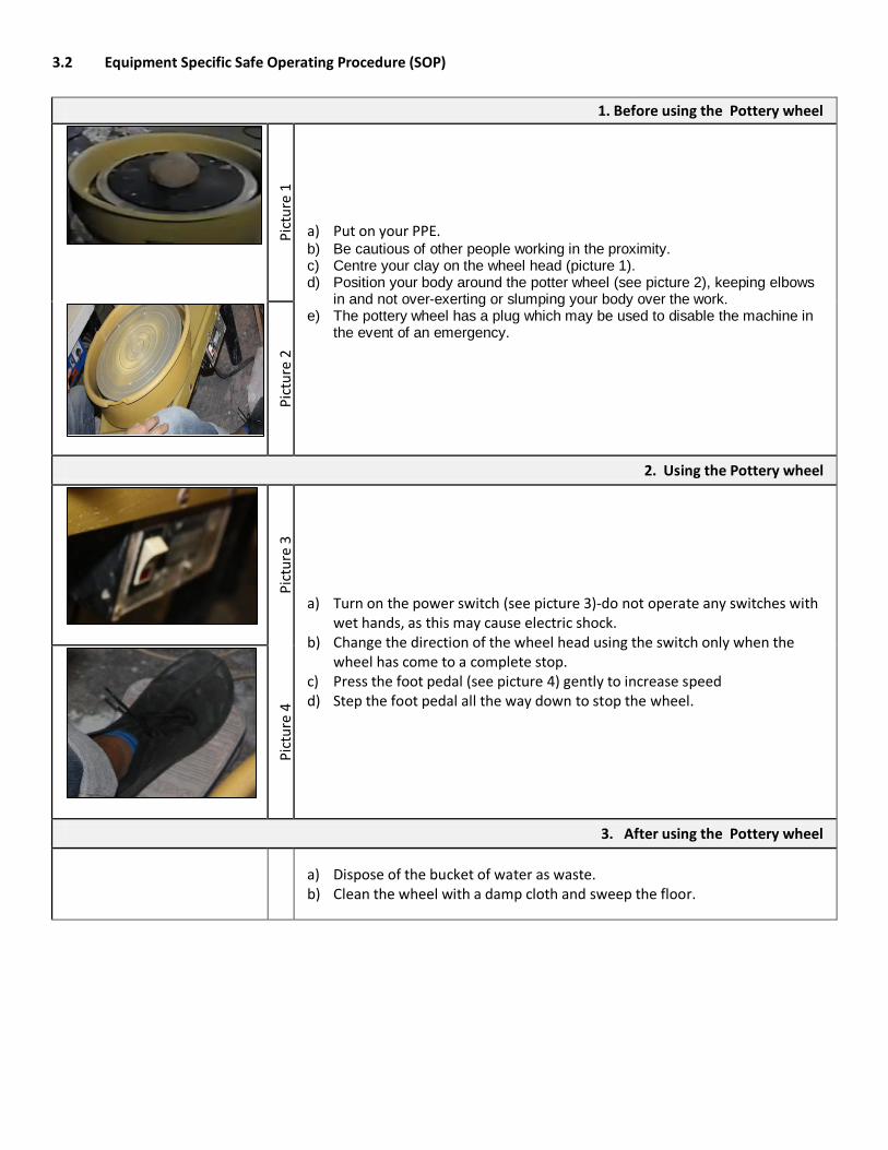
1. Before using the Pottery wheel
Pi
ctur
e 1
a) Put on your PPE. b) Be cautious of other people working in the proximity. c) Centre your clay on the wheel head (picture 1). d) Position your body around the potter wheel (see picture 2), keeping elbows
in and not over-exerting or slumping your body over the work. e) The pottery wheel has a plug which may be used to disable the machine in
the event of an emergency.
Pict
ure
2
2. Using the Pottery wheel
Pict
ure
3
a) Turn on the power switch (see picture 3)-do not operate any switches with wet hands, as this may cause electric shock.
b) Change the direction of the wheel head using the switch only when the wheel has come to a complete stop.
c) Press the foot pedal (see picture 4) gently to increase speed d) Step the foot pedal all the way down to stop the wheel.
Pict
ure
4
3. After using the Pottery wheel
a) Dispose of the bucket of water as waste. b) Clean the wheel with a damp cloth and sweep the floor.
4.0 Maintenance and Repair
4.1. Lockout/Tagout Procedure
LOCKOUT TAGOUT PROCEDURE
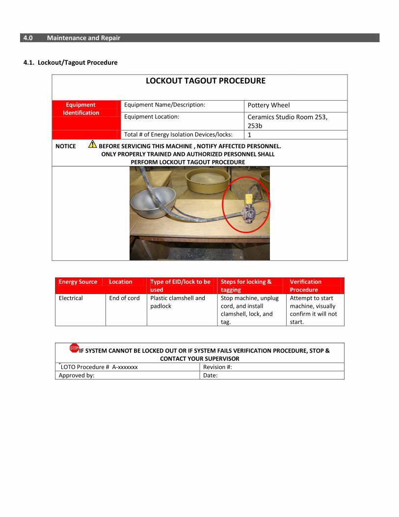
Equipment Identification
Equipment Name/Description: Pottery Wheel Equipment Location: Ceramics Studio Room 253,
253b Total # of Energy Isolation Devices/locks: 1 NOTICE BEFORE SERVICING THIS MACHINE , NOTIFY AFFECTED PERSONNEL. ONLY PROPERLY TRAINED AND AUTHORIZED PERSONNEL SHALL PERFORM LOCKOUT TAGOUT PROCEDURE
Energy Source Location Type of EID/lock to be used
Steps for locking & tagging
Verification Procedure
Electrical End of cord Plastic clamshell and padlock
Stop machine, unplug cord, and install clamshell, lock, and tag.
Attempt to start machine, visually confirm it will not start.
IF SYSTEM CANNOT BE LOCKED OUT OR IF SYSTEM FAILS VERIFICATION PROCEDURE, STOP & CONTACT YOUR SUPERVISOR
*LOTO Procedure # A-xxxxxxx Revision #: Approved by: Date:

4.2 Inspection Checklist
DAILY ✔ Ensure that the power cords are free of damage. If damaged, immediately remove electrical equipment from service until repaired.
Ensure guards are in place and in good working order. Ensure that the machine is secure and level Ensure the area around the machine is free of slip/trip hazards.
Ensure that debris/material from previous operations has been removed.
Ensure that the extruder is free of defects, wear and cracks.
Ensure that the pottery wheel is free of defects, wear and cracks.
Ensure that the splash pan is in place, without defects/damage.
Ensure that the legs are securely fastened (Tighten with wrench if necessary).
Ensure that the foot pedal cable is connected.
Ensure that the bottom cover is securely in place (To keep hands, water and other materials from coming in contact with electrical parts).
WEEKLY ✔
Ensure that connections are tight. Tighten loose connections with a wrench.
MONTHLY ✔
Clean the wheel with a damp sponge or cloth-do not pour water on the wheel.
ANNUALLY ✔
Inspect entire machine and perform maintenance as required.
5.0 Document Control
Any changes or updates to this document must be recorded and maintained.
Initially Created By: The Office of Safety and Risk Management Date: September 2011
Consultation: Studio Managers and Technicians Program Chairs and faculty
Date: January-April 2013 April – May, 2013
Approval By: VPFA and VPA Date: September, 2013
Review and Revisions Made By: Date Revised:
Changes Made(indicate sections):
Revisions Approved By: Date of Approval:

------------------------- This page intentionally left blank ---------------------------
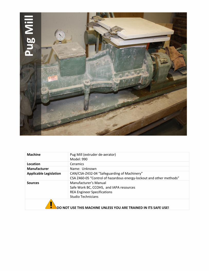
Machine Pug Mill (extruder de-aerator) Model: 990
Location Ceramics Manufacturer Name: Unknown Applicable Legislation
CAN/CSA-Z432-04 “Safeguarding of Machinery” CSA Z460-05 “Control of hazardous energy-lockout and other methods”
Sources
Manufacturer’s Manual Safe Work BC, CCOHS, and IAPA resources REA Engineer Specifications Studio Technicians
DO NOT USE THIS MACHINE UNLESS YOU ARE TRAINED IN ITS SAFE USE!
Pug
Mill

1.0 Personal Protective Equipment (PPE) Requirements
PERSONAL PROTECTIVE EQUIPMENT (PPE) REQUIRED RECOMMENDED
Face Shield / Safety Glasses with side shields ✔
Dust Mask
✔
Respirator ✔
Ear Plugs / Ear Muffs
✔
Gloves
Closed-Toe Foot Wear (no heels) ✔
Lab Coat / Protective Apron
Other
ALWAYS WEAR THE REQUIRED PPE WHEN USING THIS MACHINE!

2.0 Pre-use Inspection Checklist
Check Y N N/A
1 Are the power cords free of frays and damage?
2 Do you know where the emergency stop feature is located? The machine has an attachment plug and receptacle (plug/socket combination) and so it may be used to disable the machine in the event of an emergency.
3 Are guards in place and in good working order?
4 Is the area around the machine free of slip/trip hazards?
5 Are flammable/combustible materials (i.e. paper) and degreasing, cleaning and spraying operations removed from the immediate work area, and are you working away from sources of ignition?
6 Has the debris/material from previous operations been removed?
7 Is the pug mill secure and level to reduce vibration and movement, which could result in injury?
8 Is the pug mill free of defects and damage?
9 Is the pug mill located in a secluded area, away from most people?
10 Is the plunger/lid lever free of defects, grease and oil and kept dry?
11 Is the discharge opening clear of obstructions so that the clay can exit freely?
12 Is there a barrel or something similar in place to collect the clay at the discharge opening?
13 Is the clay going in to the in feed opening free of plastic and foreign objects?
Comments/Corrective Action:
3.0 Safe Operating Procedure (SOP)
This procedure is outlined as follows: General Safety Guidelines Equipment Specific Safety Operating Procedure 3.1 General Safety Guidelines Before using the machine, perform the following general safety checks:
• Make sure you understand all of the instructional material before operating this equipment. Failure to follow safety
instruction and warnings may result in serious personal injury, fire or property damage.
• If you have any questions or uncertainties, please ask your studio technician before use.
• Long hair, scarves, loose clothing, jewellery and ties pose an entanglement hazard. Please make sure these are all constrained prior to operating the equipment.
• Do not conduct any maintenance or repairs on this equipment. In case of a defect, contact your technician.
• Make sure the cord is kept away from heat, oil, sharp edges or moving parts and does not pose a trip hazard.
• Ensure you know where the emergency stops for your equipment are prior to use and within reach during
operation. In the absence of an emergency stop, ensure that the power switch is within reach.
• Do not remove or render machine guarding ineffective in any way.
• Ensure the work area is both well lit and organized.
3.2 Equipment Specific Safe Operating Procedure (SOP)
1. Before using the Pug Mill
Pict
ure
1
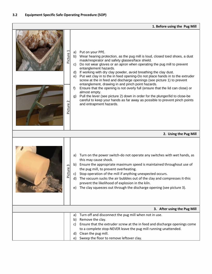
a) Put on your PPE. b) Wear hearing protection, as the pug mill is loud, closed toed shoes, a dust
mask/respirator and safety glasses/face shield. c) Do not wear gloves or an apron when operating the pug mill to prevent
entanglement hazards. d) If working with dry clay powder, avoid breathing the clay dust. e) Put wet clay in to the in feed opening-Do not place hands in to the extruder
screw at the in feed and discharge openings (see picture 1) to prevent entanglement, drawing in and pinch point hazards.
f) Ensure that the opening is not overly full (ensure that the lid can close) or almost empty.
g) Pull the lever (see picture 2) down in order for the plunger/lid to close-be careful to keep your hands as far away as possible to prevent pinch points and entrapment hazards.
Pict
ure
2
2. Using the Pug Mill
Pict
ure
3
a) Turn on the power switch-do not operate any switches with wet hands, as this may cause shock.
b) Ensure the appropriate maximum speed is maintained throughout use of the pug mill, to prevent overheating.
c) Stop operation of the mill if anything unexpected occurs. d) The vacuum sucks the air bubbles out of the clay and compresses it-this
prevent the likelihood of explosion in the kiln. e) The clay squeezes out through the discharge opening (see picture 3).
3. After using the Pug Mill
a) Turn off and disconnect the pug mill when not in use. b) Remove the clay. c) Ensure that the extruder screw at the in feed and discharge openings come
to a complete stop-NEVER leave the pug mill running unattended. d) Clean the pug mill. e) Sweep the floor to remove leftover clay.
4.0 Maintenance and Repair
4.1. Lockout/Tagout Procedure
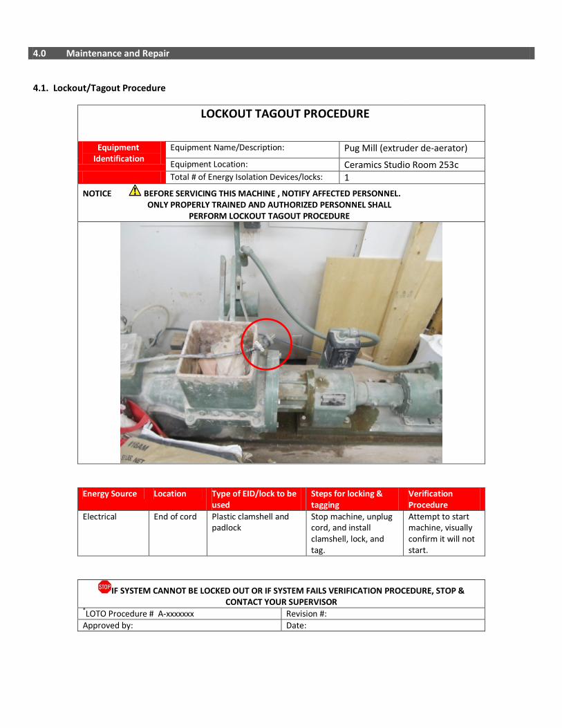
LOCKOUT TAGOUT PROCEDURE
Equipment Identification
Equipment Name/Description: Pug Mill (extruder de-aerator) Equipment Location: Ceramics Studio Room 253c
Total # of Energy Isolation Devices/locks: 1 NOTICE BEFORE SERVICING THIS MACHINE , NOTIFY AFFECTED PERSONNEL. ONLY PROPERLY TRAINED AND AUTHORIZED PERSONNEL SHALL PERFORM LOCKOUT TAGOUT PROCEDURE
Energy Source Location Type of EID/lock to be used
Steps for locking & tagging
Verification Procedure
Electrical End of cord Plastic clamshell and padlock
Stop machine, unplug cord, and install clamshell, lock, and tag.
Attempt to start machine, visually confirm it will not start.
IF SYSTEM CANNOT BE LOCKED OUT OR IF SYSTEM FAILS VERIFICATION PROCEDURE, STOP & CONTACT YOUR SUPERVISOR
*LOTO Procedure # A-xxxxxxx Revision #: Approved by: Date:

4.2 Inspection Checklist
5.0 Document Control
Any changes or updates to this document must be recorded and maintained.
Initially Created By: The Office of Safety and Risk Management Date: September 2011
Consultation: Studio Managers and Technicians Program Chairs and faculty
Date: January-April 2013 April – May, 2013
Approval By: VPFA and VPA Date: September, 2013
Review and Revisions Made By: Date Revised:
Changes Made(indicate sections):
Revisions Approved By: Date of Approval:
DAILY ✔ Ensure that the power cords are free of damage. If damaged, immediately remove electrical equipment from service until repaired.
Ensure guards are in place and in good working order. Ensure that the machine is secure and level Ensure the area around the machine is free of slip/trip hazards.
Ensure that flammable/combustible materials (i.e. paper) and degreasing, cleaning and spraying operations removed from the immediate work area.
Ensure that debris/material from previous operations has been removed.
Ensure that the pug mill is secure and level to reduce vibration and movement, which could result in injury.
Ensure that the pug mill is free of defects and damage.
Ensure that the pug mill is located in a secluded area, away from most people.
Ensure that the plunger/lid lever is free of defects, grease and oil and kept dry.
Ensure that the discharge opening is clear of obstructions so that the clay can exit freely.
Ensure that there is a barrel or something similar in place to collect the clay at the discharge opening.
WEEKLY ✔
Ensure that connections are tight. Tighten loose connections with a wrench.
MONTHLY ✔
Clean the pug mill. Lubricate bearings as necessary.
ANNUALLY ✔
Inspect entire machine and perform maintenance as required.

------------------------- This page intentionally left blank ---------------------------
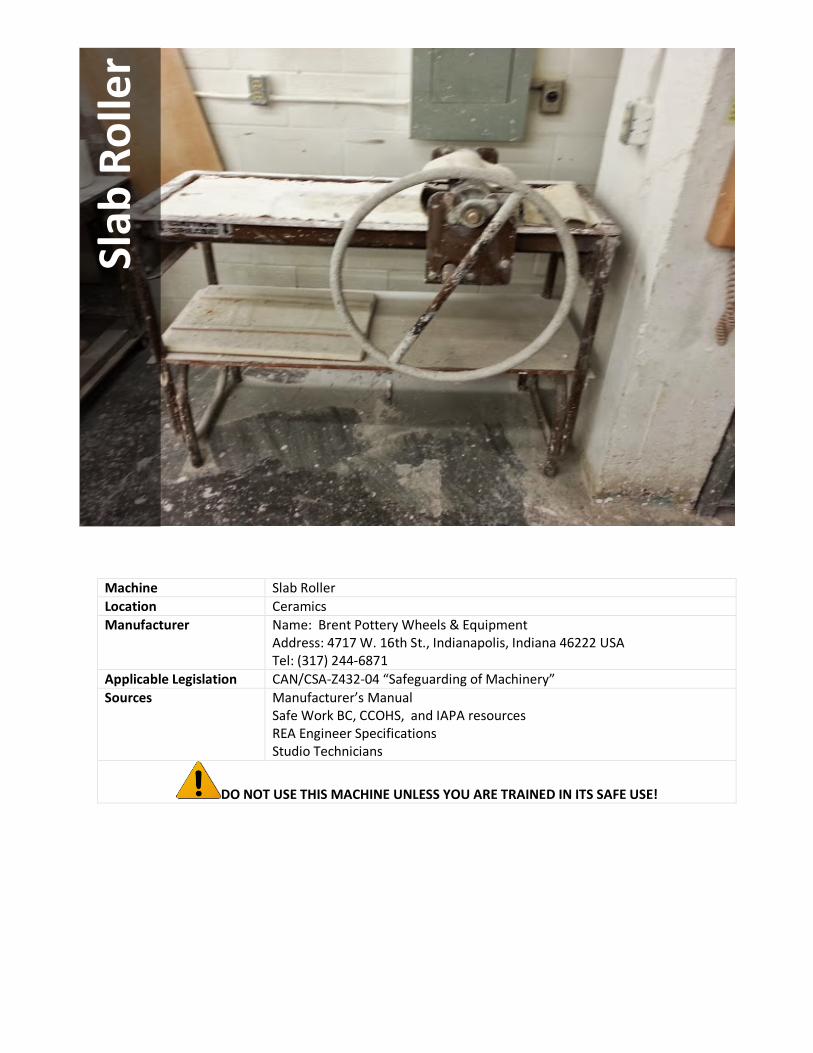
Machine Slab Roller Location Ceramics Manufacturer Name: Brent Pottery Wheels & Equipment
Address: 4717 W. 16th St., Indianapolis, Indiana 46222 USA Tel: (317) 244-6871
Applicable Legislation CAN/CSA-Z432-04 “Safeguarding of Machinery” Sources
Manufacturer’s Manual Safe Work BC, CCOHS, and IAPA resources REA Engineer Specifications Studio Technicians
DO NOT USE THIS MACHINE UNLESS YOU ARE TRAINED IN ITS SAFE USE!
Slab
Rol
ler
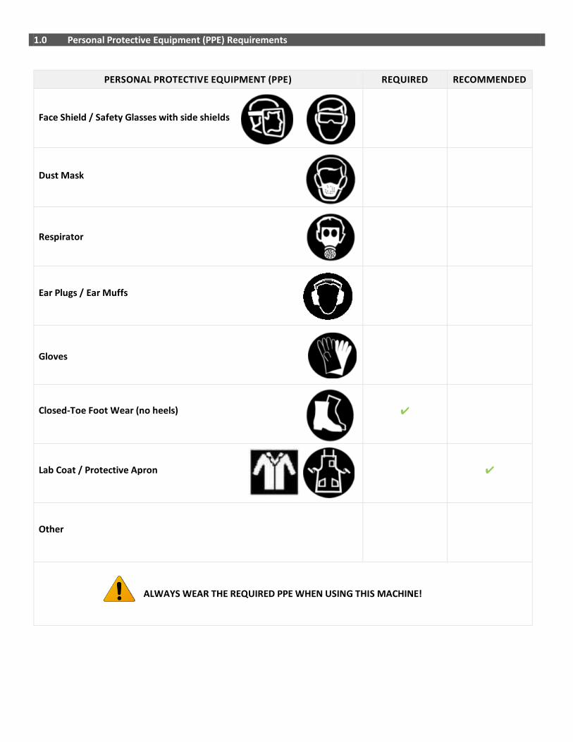
1.0 Personal Protective Equipment (PPE) Requirements
PERSONAL PROTECTIVE EQUIPMENT (PPE) REQUIRED RECOMMENDED
Face Shield / Safety Glasses with side shields
Dust Mask
Respirator
Ear Plugs / Ear Muffs
Gloves
Closed-Toe Foot Wear (no heels) ✔
Lab Coat / Protective Apron
✔
Other
ALWAYS WEAR THE REQUIRED PPE WHEN USING THIS MACHINE!

2.0 Pre-use Inspection Checklist
Check Y N N/A
1 Is the area around the slab roller free of slip/trip hazards?
2 Has the debris/material from previous operations been removed?
3 Is the bed, handle, roller and canvasses/boards free of defects?
4 Does the handle and roller move freely without obstruction?
5 Are you using the correct material and thickness for the machine?
Comments/Corrective Action:
3.0 Safe Operating Procedure (SOP) This procedure is outlined as follows: General Safety Guidelines Equipment Specific Safety Operating Procedure 3.1 General Safety Guidelines Before using the machine, perform the following general safety checks:
• Make sure you understand all of the instructional material before operating this equipment. Failure to follow safety
instruction and warnings may result in serious personal injury, fire or property damage.
• If you have any questions or uncertainties, please ask your studio technician before use.
• Long hair, scarves, loose clothing, jewellery and ties pose an entanglement hazard. Please make sure these are all constrained prior to operating the equipment.
• Do not conduct any maintenance or repairs on this equipment. In case of a defect, contact your technician.
• Ensure you know where the emergency stops for your equipment are prior to use and within reach during
operation. In the absence of an emergency stop, ensure that the power switch is within reach.
• Do not remove or render machine guarding ineffective in any way.
• Ensure the work area is both well lit and organized.
3.2 Equipment Specific Safe Operating Procedure (SOP)
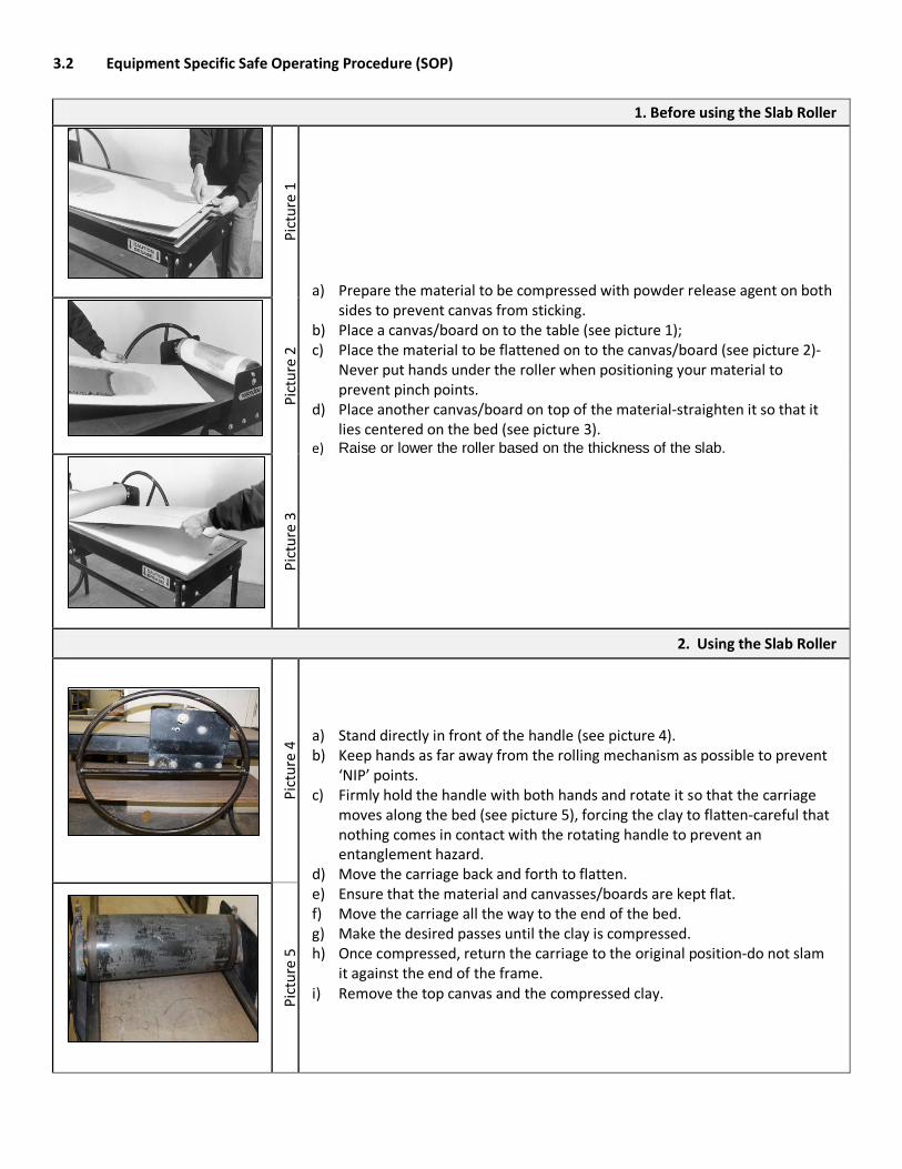
1. Before using the Slab Roller
Pi
ctur
e 1
a) Prepare the material to be compressed with powder release agent on both sides to prevent canvas from sticking.
b) Place a canvas/board on to the table (see picture 1); c) Place the material to be flattened on to the canvas/board (see picture 2)-
Never put hands under the roller when positioning your material to prevent pinch points.
d) Place another canvas/board on top of the material-straighten it so that it lies centered on the bed (see picture 3).
e) Raise or lower the roller based on the thickness of the slab.
Pict
ure
2
Pict
ure
3
2. Using the Slab Roller
Pict
ure
4 a) Stand directly in front of the handle (see picture 4).
b) Keep hands as far away from the rolling mechanism as possible to prevent ‘NIP’ points.
c) Firmly hold the handle with both hands and rotate it so that the carriage moves along the bed (see picture 5), forcing the clay to flatten-careful that nothing comes in contact with the rotating handle to prevent an entanglement hazard.
d) Move the carriage back and forth to flatten. e) Ensure that the material and canvasses/boards are kept flat. f) Move the carriage all the way to the end of the bed. g) Make the desired passes until the clay is compressed. h) Once compressed, return the carriage to the original position-do not slam
it against the end of the frame. i) Remove the top canvas and the compressed clay.
Pict
ure
5

4. After using the Slab Roller
a) Clean the area and canvasses/boards. NEVER clean the roller while it is in motion.
b) Use a moist sponge to wipe the floor surrounding the roller. c) Wash your hands.
4.0 Maintenance and Repair
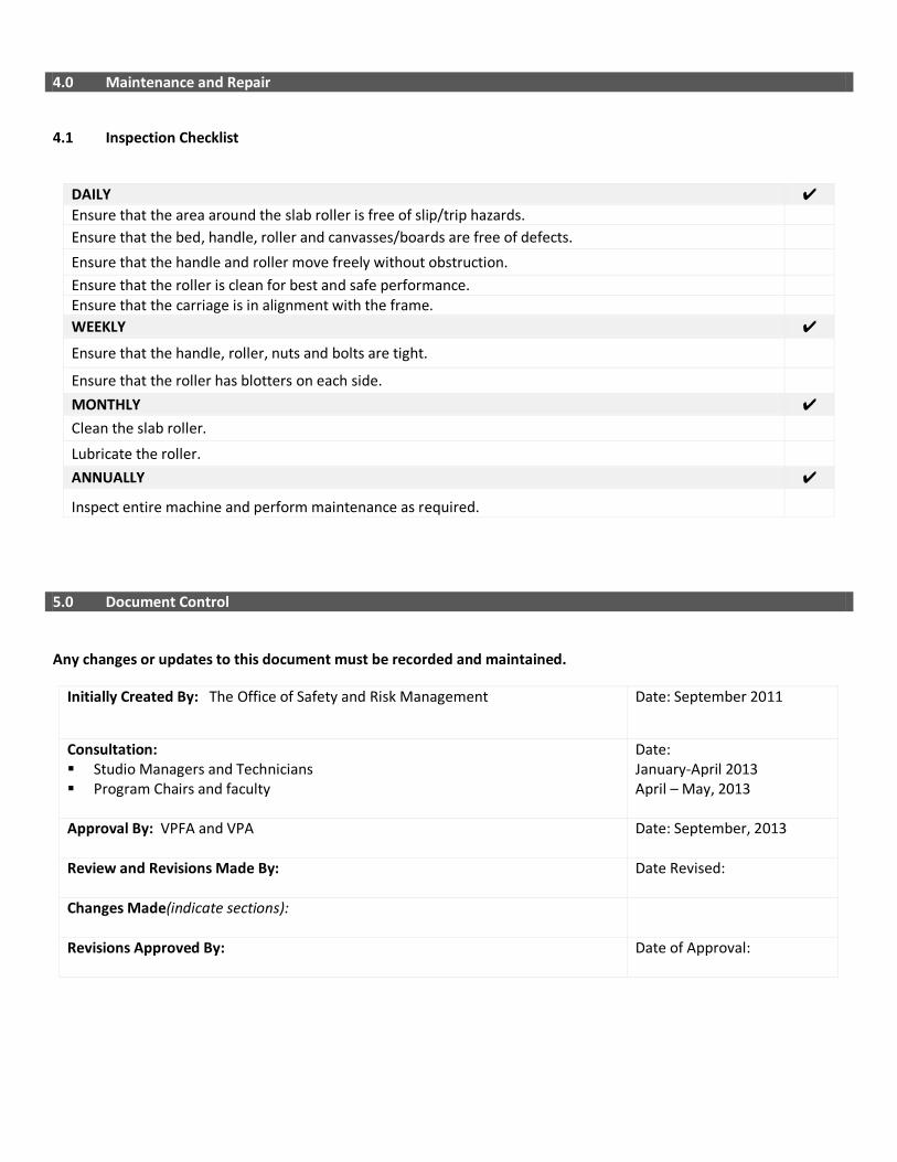
4.1 Inspection Checklist
5.0 Document Control
Any changes or updates to this document must be recorded and maintained.
Initially Created By: The Office of Safety and Risk Management Date: September 2011
Consultation: Studio Managers and Technicians Program Chairs and faculty
Date: January-April 2013 April – May, 2013
Approval By: VPFA and VPA Date: September, 2013
Review and Revisions Made By: Date Revised:
Changes Made(indicate sections):
Revisions Approved By: Date of Approval:
DAILY ✔ Ensure that the area around the slab roller is free of slip/trip hazards. Ensure that the bed, handle, roller and canvasses/boards are free of defects.
Ensure that the handle and roller move freely without obstruction.
Ensure that the roller is clean for best and safe performance. Ensure that the carriage is in alignment with the frame. WEEKLY ✔
Ensure that the handle, roller, nuts and bolts are tight.
Ensure that the roller has blotters on each side.
MONTHLY ✔ Clean the slab roller.
Lubricate the roller.
ANNUALLY ✔
Inspect entire machine and perform maintenance as required.