Embed Size (px)
Citation preview
CeramicsWindows To The Future
A MAST Module
Materials Science and Technology
1995
ii
Acknowledgments
The authors would like to thank the following people for their advice and support in the development of this module:
Dr. Jennifer LewisDirector of the Materials Science Workshop
Dr. James AdamsAssistant Director
Dr. John KiefferDepartment of Material Science and EngineeringUniversity of Illinois Urbana-Champaign, Urbana, IL
Joe GrindleyUniversity of Illinois Ceramics Lab Coordinator
Authors:
George BaehrHarlem Consolidated School District 122, Loves Park, IL
Jerald DayTurkey Run High School, Marshall, IN
Laurel DieskowOak Forest High School, Oak Forest, IL
Diane FauliseStillwater Area High School;, Stilllwater, MN
Elizabeth OverockerAntioch Community High School, Antioch, WI
John J. SchwanUniversity of Illinois, Urbana, IL
iii

iv
Foreword
This module is intended as a curriculum supplement for high school science teachers who would like to introduce their students to concepts in Materials Science and Technolology. Teachers are urged to use one, some, or all of the MAST modules. Some teachers may wish to implement this module in its entirety as a subject unit in a course. Others may wish to utilize only part of the module, perhaps a laboratory experiment. We encourage teachers to reproduce and use these materials in their classrooms and to contact the workshop with any assessment, comments, or suggestions they may have.
This is one in a series of MAST modules developed and revised during the Materials Technology Workshop held at the University of Illinois at Urbana-Champaign during 1993-'95.
A combination of university professors, high school science teachers, and undergraduates, worked together to create and revise this module over a three year period.
Financial support for the Materials Technology Workshop was provided by the National Science Foundation (NSF) Education and Human Resource Directorate (Grant # ESI 92-53386) Other contributors include the NSF Center for Advanced Cement Based Materials, the Dow Chemical Foundation, the Materials Research Society, the Iron and Steel Society, and the Peoria Chapter of the American Society for Metals. The University of Illinois at Urbana-Champaign Department of Materials Science and Engineering and the College of Engineering Office of Extramural Education provided organizational support.
v

vi
Table of Contents
Acknowledgments .......................................................................... ii
Foreword .................................................................................... iii
Introduction ................................................................................. 1
F. Y. I. ...................................................................................... 2
What are Ceramics? ......................................................................... 3
Historical Timeline .......................................................................... 4
Future Trends ................................................................................ 6
Scientific Principles ......................................................................... 7Introduction ........................................................................ 7Atomic Bonding ................................................................... 7Classification ...................................................................... 8Thermal Properties ................................................................ 9Optical Properties .................................................................. 13Mechanical Properties ............................................................ 15Electrical Properties .............................................................. 17Ceramic Processing ............................................................... 21Summary ........................................................................... 24
References .................................................................................... 25
Resources .................................................................................... 26
Equipment and Materials Grid ............................................................. 27
Laboratory Activities ........................................................................ 28 Clay Labs: Ready - Beam - Fire ................................................ 28 Flocculation Demonstration: In School Suspensions ......................... 35 Glass Labs: Wow, You Can See Right Through Me! ........................ 37 Electrical Resistance in a Glass Bulb Demo .................................... 45 Fiber Optics Lab: Light at the End of the Tunnel .............................. 46
Module Quiz .................................................................................. 50
Glossary ...................................................................................... 52
Introduction
Module Objective:
The objective of this module is to explore the world of ceramic materials through applications, properties, and processing.
Key Concepts:
• Examples and applications of ceramic materials• Ceramic bonding mechanisms and how they influence properties• Properties of ceramics (mechanical, electrical, thermal, and optical). • Preparation and testing of crystalline and amorphous ceramic materials
Prerequisites:
Some familiarity with the following concepts would be helpful in the understanding of the information in this module.
• Basic chemical bonding (ionic & covalent)• Electronegativity• Hydrated materials• Density
Placement in Curriculum:
This module could be included in a chemistry course with crystalline structure, density or bonding; in physics with mechanics, heat, optics,and electronics; and in general/tech science as an application of materials in their lives.
1
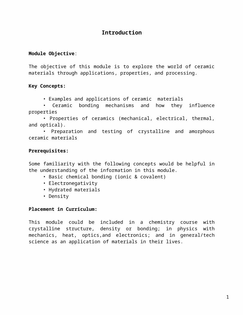
Pottery
Brick
Electronics
ArtificialBones
TurbineBlades
Cutting Tools
SpaceShuttleTiles
CeramicsConventional
Advanced
F. Y. I. :
Ceramics are materials that are composed of inorganic substances (usually a combination of metallic and nonmetallic elements). Just where in your life would you use items based on ceramic materials? Let’s look at a scenario that we all have in common.
"Beeeeppp," the alarm clock sounds to roust you from your sleep. The electricity that kept that clock ticking all night was generated, stored, and traveled through a whole array of ceramic products such as transducers, resistors, and various insulators. You turn on the light which is encased in a glass (ceramic) bulb.
Up and going, your feet hit the ceramic tiled floor of the bathroom as you drag yourself over to the slip casted ceramic throne (toilet). Duty attended to, you head for the ceramic sink where hands and teeth are cleaned (even the ceramic one that was implanted after that athletic accident). Before you step into the shower, you warm up the room with the electric heater that contains ceramic heating elements.
"Brrrinnng," the phone, which contains a ceramic microphone that can transmit your voice through fiber optic lines, rings. “Hello,” and in the background you detect that “click - click“ of a computer which contains ceramic-based microelectronic packages that house silicon wafers.
The bathroom has warmed. You pause to look out over the snow covered lawn and contemplate adding another layer of fiber glass insulation to help hold the heat in the house. You realize that you really don’t want to put those pink
2
fiberglass rolls into your brand new car, which in itself contains over 70 pounds of ceramic sensors and parts.
"Zoooommmm," overhead a jet passes by, and you think about the returning space shuttle and its many uses of ceramic materials from the nose cone to the heat shielding tiles.
We could continue our journey through the day, but maybe you ought to explore what ceramics are. Would you like to discover what special properties ceramics have, and why? Or you could even find out what applications exist in today's, as well as tomorrow's world of ceramics.
3
What Are Ceramics?
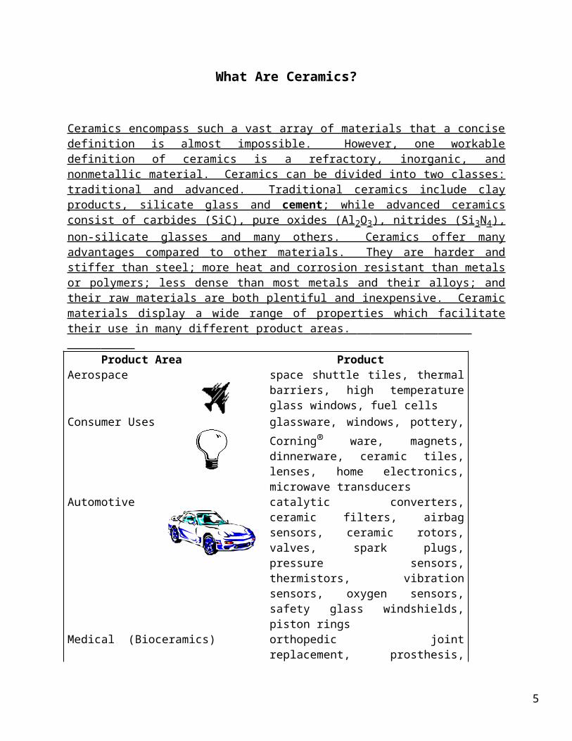
Ceramics encompass such a vast array of materials that a concise definition is almost impossible. However, one workable definition of ceramics is a refractory, inorganic, and nonmetallic material. Ceramics can be divided into two classes: traditional and advanced. Traditional ceramics include clay products, silicate glass and cement ; while advanced ceramics consist of carbides (SiC), pure oxides (Al2O3), nitrides (Si3N4), non-silicate glasses and many others. Ceramics offer many advantages compared to other materials. They are harder and stiffer than steel; more heat and corrosion resistant than metals or polymers; less dense than most metals and their alloys; and their raw materials are both plentiful and inexpensive. Ceramic materials display a wide range of properties which facilitate their use in many different product areas.
Product Area ProductAerospace space shuttle tiles, thermal barriers, high
temperature glass windows, fuel cells
Consumer Uses glassware, windows, pottery, Corning® ware, magnets, dinnerware, ceramic tiles, lenses, home electronics, microwave transducers
Automotive catalytic converters, ceramic filters, airbag sensors, ceramic rotors, valves, spark plugs, pressure sensors, thermistors, vibration sensors, oxygen sensors, safety glass windshields, piston rings
Medical (Bioceramics)
orthopedic joint replacement, prosthesis, dental restoration, bone implants
Military structural components for ground, air and naval vehicles, missiles, sensors
Computers insulators, resistors, superconductors, capacitors, ferroelectric components, microelectronic packaging
Other Industries bricks, cement, membranes and filters, lab equipment
Communications
fiber optic/laser communications, TV and radio components, microphones
4
Humans have found applications for ceramics for the past 30,000 years; every day new and different applications are being discovered. This truly makes ceramics a stone age material, with space age qualities.
5

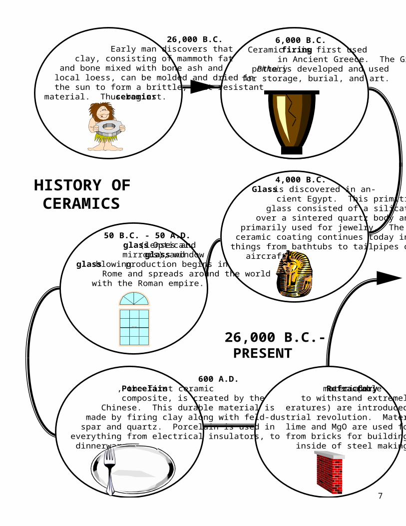
6,000 B.C. Ceramic firing is first used in Ancient Greece. The Greek pottery Pithoi is developed and used for storage, burial, and art.
4,000 B.C. Glass is discovered in an- cient Egypt. This primitive glass consisted of a silicate glaze over a sintered quartz body and was primarily used for jewelry. The use of ceramic coating continues today in many things from bathtubs to tailpipes of jet aircraft.
50 B.C. - 50 A.D. Optical glass (lenses and mirrors), window glass and glass blowing production begins in Rome and spreads around the world with the Roman empire.
600 A.D. Porcelain, the first ceramic composite, is created by the Chinese. This durable material is made by firing clay along with feld- spar and quartz. Porcelain is used in everything from electrical insulators, to dinnerware.
1870’s Refractory materials (able to withstand extremely high temp- eratures) are introduced during the In- dustrial revolution. Materials made from lime and MgO are used for everything from bricks for buildings to lining the inside of steel making furnaces.
26,000 B.C. Early man discovers that clay, consisting of mammoth fat and bone mixed with bone ash and local loess, can be molded and dried in the sun to form a brittle, heat-resistant material. Thus begins ceramic art.
HISTORY OF CERAMICS
26,000 B.C.- PRESENT
6
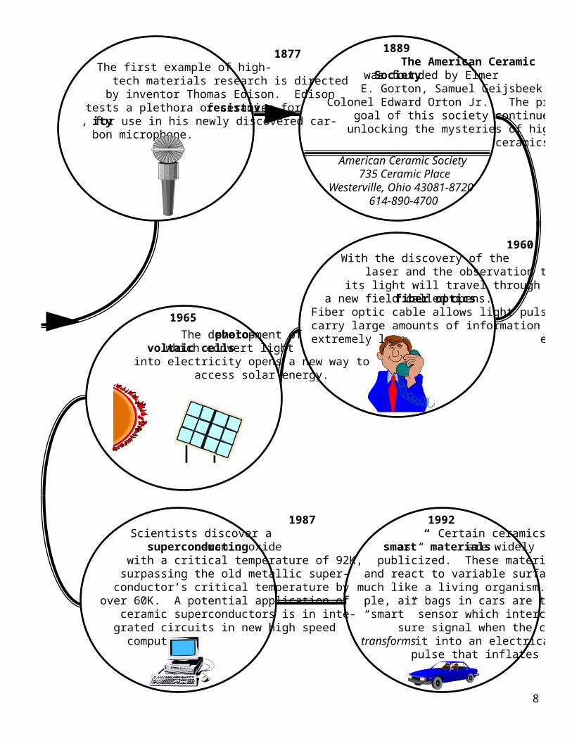
1877 The first example of high- tech materials research is directed by inventor Thomas Edison. Edison tests a plethora of ceramics for resistiv- ity, for use in his newly discovered car- bon microphone.
1889 The American Ceramic Society was founded by Elmer E. Gorton, Samuel Geijsbeek and Colonel Edward Orton Jr.. The primary goal of this society continues to be unlocking the mysteries of high-tech ceramics.
American Ceramic Society 735 Ceramic Place
Westerville, Ohio 43081-8720 614-890-4700
1960 With the discovery of the laser and the observation that its light will travel through glass, a new field called fiber optics opens. Fiber optic cable allows light pulses to carry large amounts of information with extremely low energy loss. The development of photo-
voltaic cells which convert light into electricity opens a new way to access solar energy.
1987 Scientists discover a superconducting ceramic oxide with a critical temperature of 92K, surpassing the old metallic super- conductor’s critical temperature by over 60K. A potential application of ceramic superconductors is in inte- grated circuits in new high speed computers.
1992 Certain ceramics known as “smart” materials are widely publicized. These materials can sense and react to variable surface conditions, much like a living organism. For exam- ple, air bags in cars are triggered by a “smart” sensor which intercepts a pres- sure signal when the car is hit and transforms it into an electrical im- pulse that inflates the bag.
1965
7
Future Trends
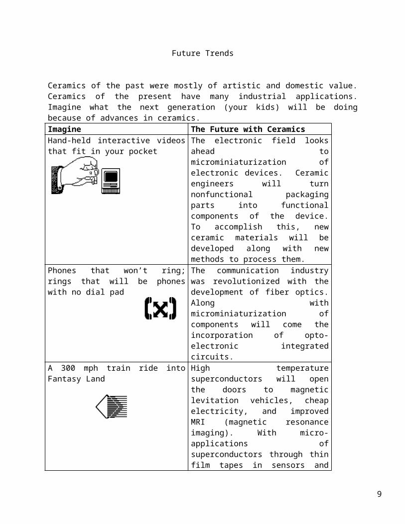
Ceramics of the past were mostly of artistic and domestic value. Ceramics of the present have many industrial applications. Imagine what the next generation (your kids) will be doing because of advances in ceramics.Imagine The Future with CeramicsHand-held interactive videos that fit in your pocket
The electronic field looks ahead to microminiaturization of electronic devices. Ceramic engineers will turn nonfunctional packaging parts into functional components of the device. To accomplish this, new ceramic materials will be developed along with new methods to process them.
Phones that won’t ring; rings that will be phones with no dial pad
The communication industry was revolutionized with the development of fiber optics. Along with microminiaturization of components will come the incorporation of opto-electronic integrated circuits.
A 300 mph train ride into Fantasy Land High temperature superconductors will open the doors to magnetic levitation vehicles, cheap electricity, and improved MRI (magnetic resonance imaging). With micro-applications of superconductors through thin film tapes in sensors and memory storage devices, the use of superconductors will take-off.
A high speed electric car powered with a fuel cell and full of high tech sensors that practically drive the car for you
The automobile industry, which already incorporates seventy pounds of ceramics into a car, is looking to the field of ceramics to provide improved sensors of motion, gas compositions, electrical and thermal changes; as well as light weight, high strength and high temperature components for the engines. For the conservation of energy and environmental protection, ceramics seem to be a viable possibility in the use of ceramic fuel cells, batteries, photovoltaic cells, and fiber optic transmission of energy.
A best friend that‘s bionic/andromic with microscopic hearing and seeing devices and a skeletal system all made from ceramics
Besides the ceramic applications in medical diagnostic instruments, the field of bioceramics for bone replacement and chemotherapy release capsules is here. As ceramic materials improve in terms of
8
strength, nonreactivity, compatibility, longevity, porosity for tissue growth, and lower costs, more use of ceramic devices will be seen.
9
Scientific Principles
Introduction:
Ceramics have characteristics that enable them to be used in a wide variety of applications including:
• high heat capacity and low heat conductance• corrosion resistance• electrically insulating, semiconducting, or superconducting• nonmagnetic and magnetic• hard and strong, but brittle
The diversity in their properties stems from their bonding and crystal structures.
Atomic Bonding:
Two types of bonding mechanisms occur in ceramic materials, ionic and covalent. Often these mechanisms co-exist in the same ceramic material. Each type of bond leads to different characteristics.
Ionic bonds most often occur between metallic and nonmetallic elements that have large differences in their electronegativities. Ionically-bonded structures tend to have rather high melting points, since the bonds are strong and non-directional.
The other major bonding mechanism in ceramic structures is the covalent bond. Unlike ionic bonds where electrons are transferred, atoms bonded covalently share electrons. Usually the elements involved are nonmetallic and have small electronegativity differences.
Many ceramic materials contain both ionic and covalent bonding. The overall properties of these materials depend on the dominant bonding mechanism. Compounds that are either mostly ionic or mostly covalent have higher melting points than compounds in which neither kind of bonding predominates.
Table 1: Comparison of % Covalent and Ionic character with several ceramic compound's melting points.
Ceramic Compound
Melting Point ˚C % Covalent character
% Ionic character
Magnesium Oxide 2798˚ 27% 73%Aluminum Oxide 2050˚ 37% 63%Silicon Dioxide 1715˚ 49% 51%Silicon Nitride 1900˚ 70% 30%Silicon Carbide 2500˚ 89% 11%
10
Classification:
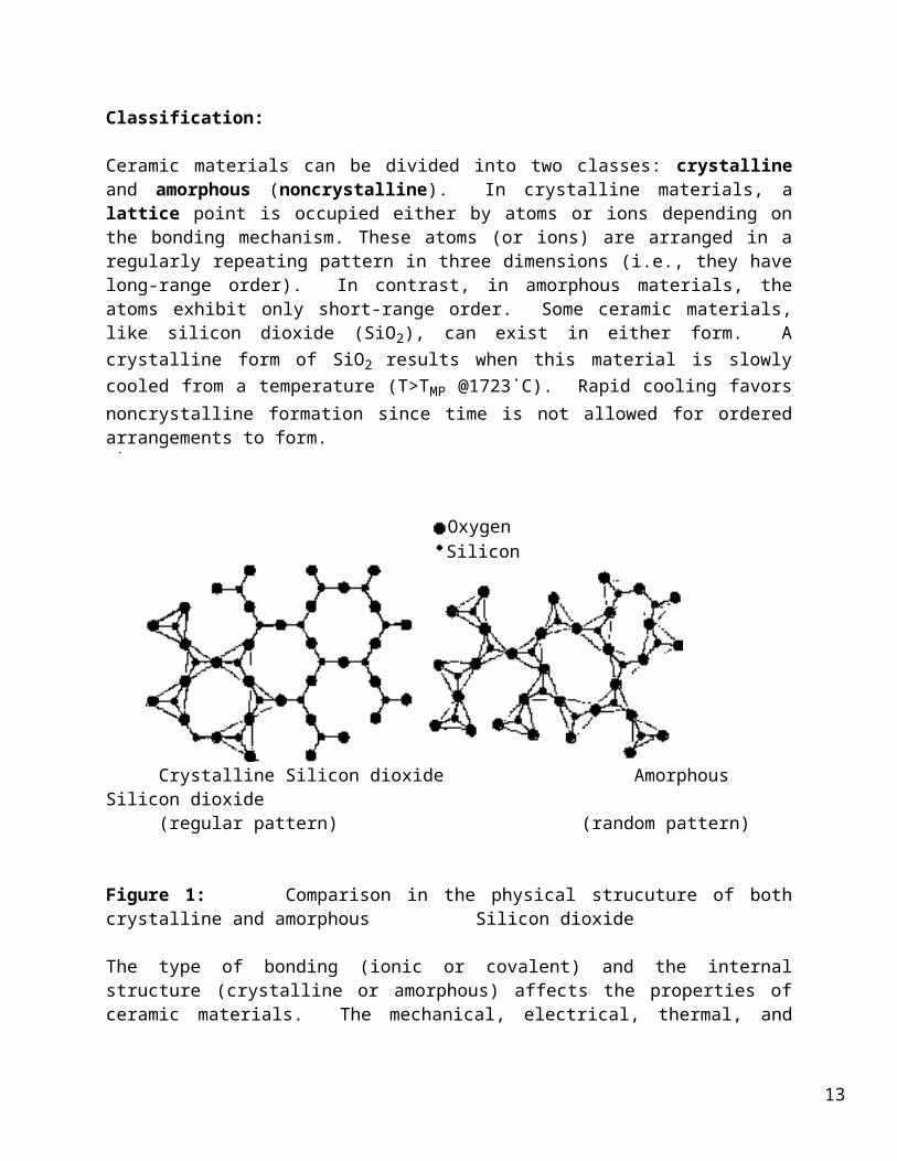
Ceramic materials can be divided into two classes: crystalline and amorphous (noncrystalline). In crystalline materials, a lattice point is occupied either by atoms or ions depending on the bonding mechanism. These atoms (or ions) are arranged in a regularly repeating pattern in three dimensions (i.e., they have long-range order). In contrast, in amorphous materials, the atoms exhibit only short-range order. Some ceramic materials, like silicon dioxide (SiO2), can exist in either form. A crystalline form of SiO2 results when this material is slowly cooled from a temperature (T>TMP @1723˙C). Rapid cooling favors noncrystalline formation since time is not allowed for ordered arrangements to form.
OxygenSilicon
Crystalline Silicon dioxide Amorphous Silicon dioxide(regular pattern) (random pattern)
Figure 1: Comparison in the physical strucuture of both crystalline and amorphous Silicon dioxide
The type of bonding (ionic or covalent) and the internal structure (crystalline or amorphous) affects the properties of ceramic materials. The mechanical, electrical, thermal, and optical properties of ceramics will be discussed in the following sections.
11
Thermal Properties:
The most important thermal properties of ceramic materials are heat capacity, thermal expansion coefficient, and thermal conductivity. Many applications of ceramics, such as their use as insulating materials, are related to these properties.
Thermal energy can be either stored or transmitted by a solid. The ability of a material to absorb heat from its surrounding is its heat capacity. In solid materials at T > 0 K, atoms are constantly vibrating. The atomic vibrations are also affected by the vibrations of adjacent atoms through bonding. Hence, vibrations can be transmitted across the solid. The higher the temperature, the higher the frequency of vibration and the shorter the wavelength of the associated elastic deformation.
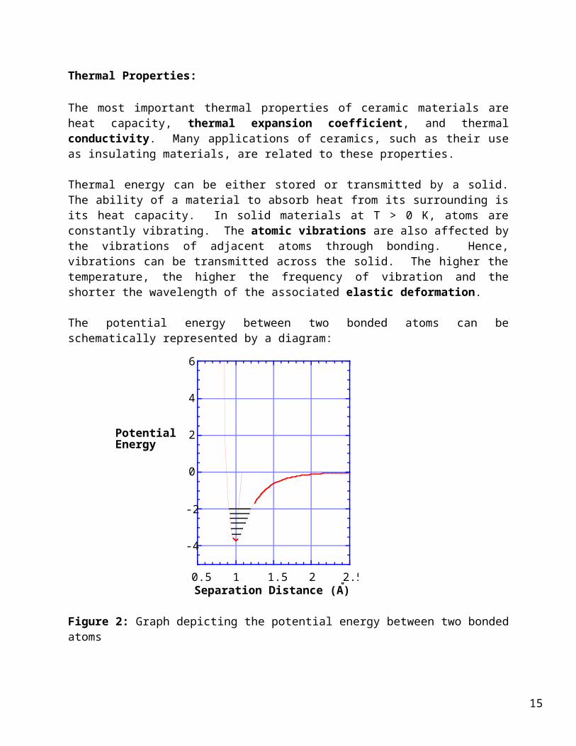
The potential energy between two bonded atoms can be schematically represented by a diagram:
Separation Distance (A)
-4
-2
0
2
4
6
0.5 1 1.5 2 2.5Separation Distance (Å)
PotentialEnergy
Figure 2: Graph depicting the potential energy between two bonded atoms
The distance at which there is minimum energy (potential well) represents what is usually described as the bond length. A good analogy is a sphere attached to a spring, with the equilibrium position of the spring corresponding to the atom at the bond length (potential well). When the spring is either compressed or stretched from its equilibrium position, the force pulling it back to the equilibrium position is directly proportional to the displacement (Hooke's law). Once displaced, the frequency of oscillation is greatest when there is a large spring constant and low mass ball. Ceramics generally have strong bonds and light atoms. Thus, they can have high frequency vibrations of the atoms with small disturbances in the crystal lattice. The result is that they typically have both high heat capacities and high melting temperatures.
12
As temperature increases, the vibrational amplitude of the bonds increases. The asymmetry of the curve shows that the interatomic distance also increases with temperature, and this is observed as thermal expansion. Compared to other materials, ceramics with strong bonds have potential energy curves that are deep and narrow and correspondingly small thermal expansion coefficients.
The conduction of heat through a solid involves the transfer of energy between vibrating atoms. Extending the analogy, consider each sphere (atom) to be connected to its neighbors by a network of springs (bonds). The vibration of each atom affects the motion of neighboring atoms, and the result is elastic waves that propagate through the solid. At low temperatures (up to about 400˚C), energy travels through the material predominantly via phonons, elastic waves that travel at the speed of sound. Phonons are the result of particle vibrations which increase in frequency and amplitude as temperature increases.
Phonons travel through the material until they are scattered, either through phonon-phonon interactions* or at lattice imperfections. Phonon conductivity generally decreases with increasing temperature in crystalline materials as the amount of scattering increases. Amorphous ceramics which lack the ordered lattice undergo even greater scattering, and therefore are poor conductors. Those ceramic materials that are composed of particles of similar size and mass with simple structures (such as diamond or BeO) undergo the smallest amount of scattering and therefore have the greatest conductivity.
At higher temperatures, photon conductivity (radiation) becomes the predominant mechanism of energy transfer. This is a rapid sequence of absorptions and emissions of photons that travel at the speed of light. This mode of conduction is especially important in glass, transparent crystalline ceramics, and porous ceramics. In these materials, thermal conductivity increases with increased temperature.
Although the thermal conductivity is affected by faults or defects in the crystal structure, the insulating properties of ceramics essentially depend on microscopic imperfections. The transmission of either type of wave (phonon or photon) is interrupted by grain boundaries and pores, so that more porous materials are better insulators. The use of ceramic insulating materials to line kilns and industrial furnaces are one application of the insulating properties of ceramic materials.
The electron mechanism of heat transport is relatively unimportant in ceramics because charge is localized. This mechanism is very important, however, in metals which have large numbers of free (delocalized) electrons.
*Phonon-phonon interactions are another consequence of the asymmetry in the interaction potential between atoms. When different phonons overlap at the location of a particular atom, the vibrational amplitudes superimpose. In the asymmetrical potential well, the curvature varies as a function of the displacement. This means that the spring constant by which the atom is retained also changes. Hence the atom has the tendency to vibrate with a different frequency, which produces a different phonon.
13
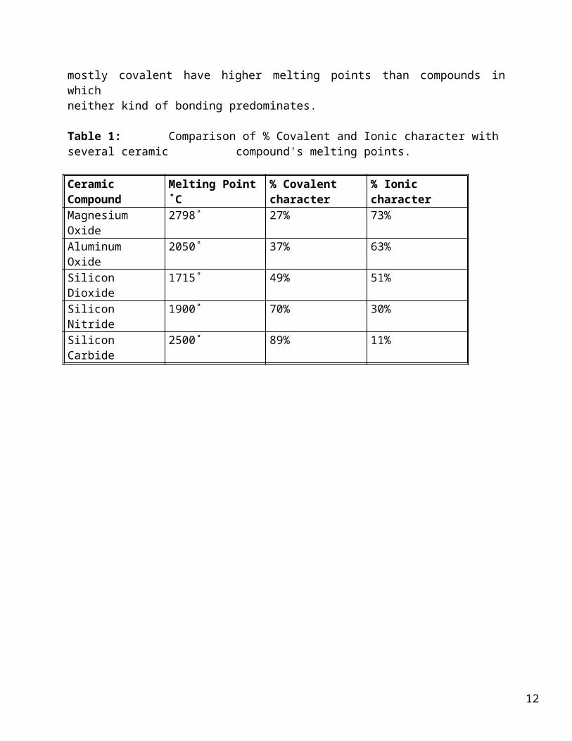
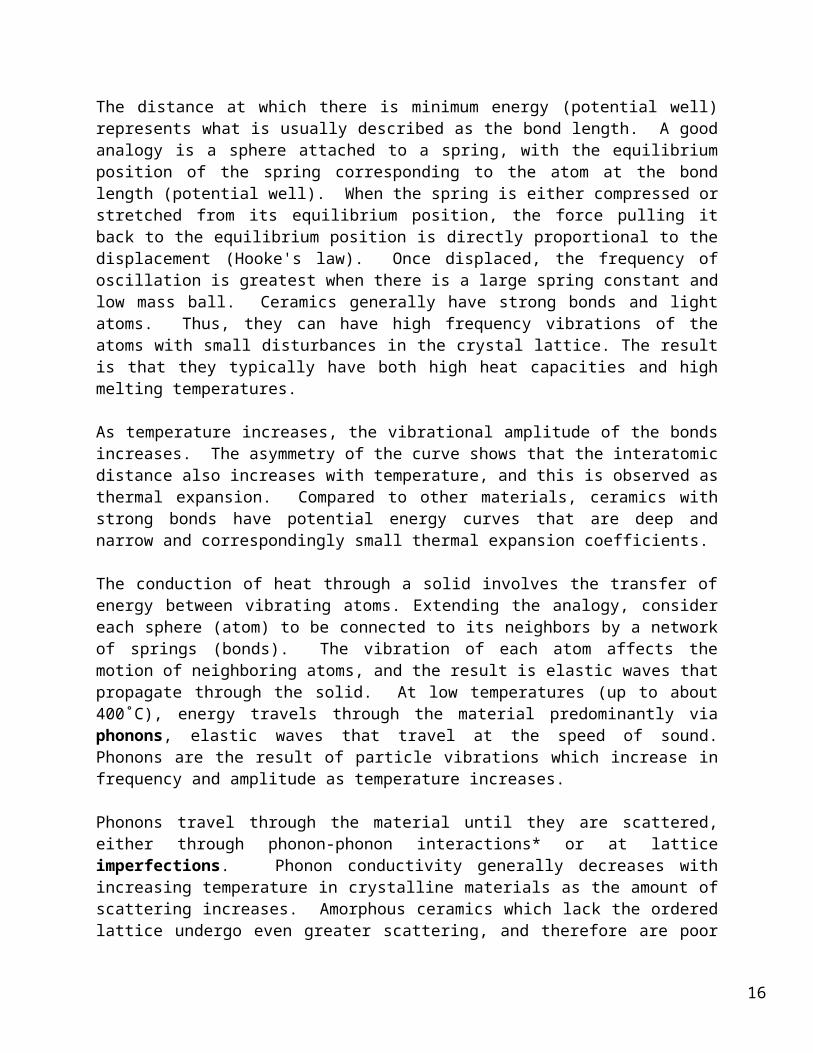
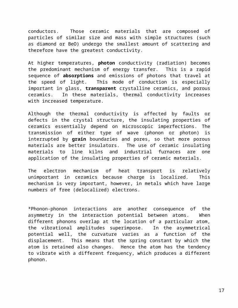
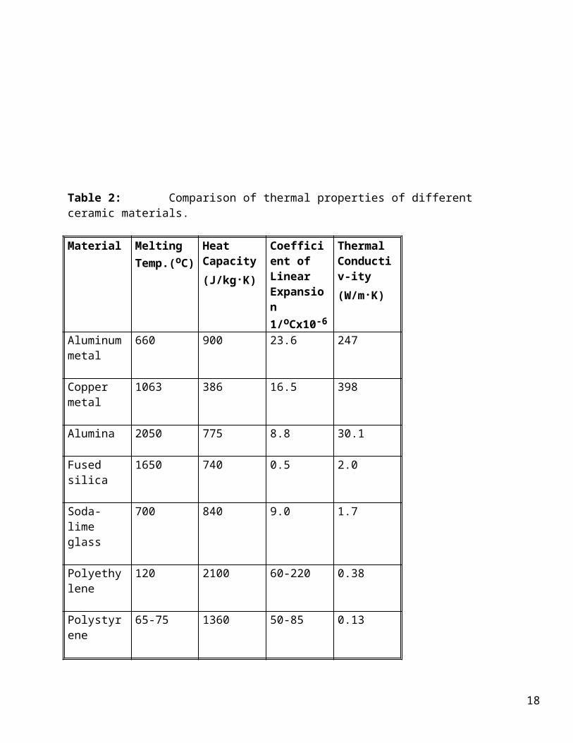
Table 2: Comparison of thermal properties of different ceramic materials.
Material Melting Temp.(oC)
Heat Capacity (J/kg.K)
Coefficient of Linear Expansion 1/oCx10-6
Thermal Conductiv-ity (W/m.K)
Aluminum metal
660 900 23.6 247
Copper metal
1063 386 16.5 398
Alumina 2050 775 8.8 30.1
Fused silica 1650 740 0.5 2.0
Soda-lime glass
700 840 9.0 1.7
Polyethylene 120 2100 60-220 0.38
Polystyrene 65-75 1360 50-85 0.13
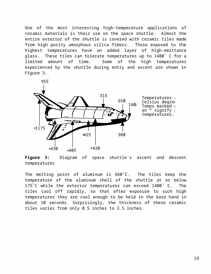
One of the most interesting high-temperature applications of ceramic materials is their use on the space shuttle. Almost the entire exterior of the shuttle is covered with ceramic tiles made from high purity amorphous silica fibers. Those exposed to the highest temperatures have an added layer of high-emittance glass. These tiles can tolerate temperatures up to 1480˚ C for a limited amount of time. Some of the high temperatures experienced by the shuttle during entry and ascent are shown in Figure 3.
14
955
1175
430 405
425
420
980
1465650
315 Temperatures are in Celsius degrees. Temps marked with an * signify ascent temperatures.
*
* * *
*
Figure 3: Diagram of space shuttle's ascent and descent temperatures
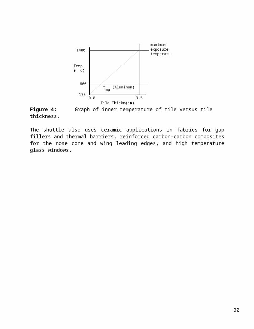
The melting point of aluminum is 660˚C. The tiles keep the temperature of the aluminum shell of the shuttle at or below 175˚C while the exterior temperatures can exceed 1400˚ C. The tiles cool off rapidly, so that after exposure to such high temperatures they are cool enough to be held in the bare hand in about 10 seconds. Surprisingly, the thickness of these ceramic tiles varies from only 0.5 inches to 3.5 inches.
maximum exposuretemperature
1480
Temp( C)
660
1750.0
Tile Thickness 3.5
(Aluminum)Tmp
(in)Figure 4: Graph of inner temperature of tile versus tile thickness.
The shuttle also uses ceramic applications in fabrics for gap fillers and thermal barriers, reinforced carbon-carbon composites for the nose cone and wing leading edges, and high temperature glass windows.
15

16
17
Incident Light
Air
Water orGlass
Refracted Light
1
2
18
19
20
21
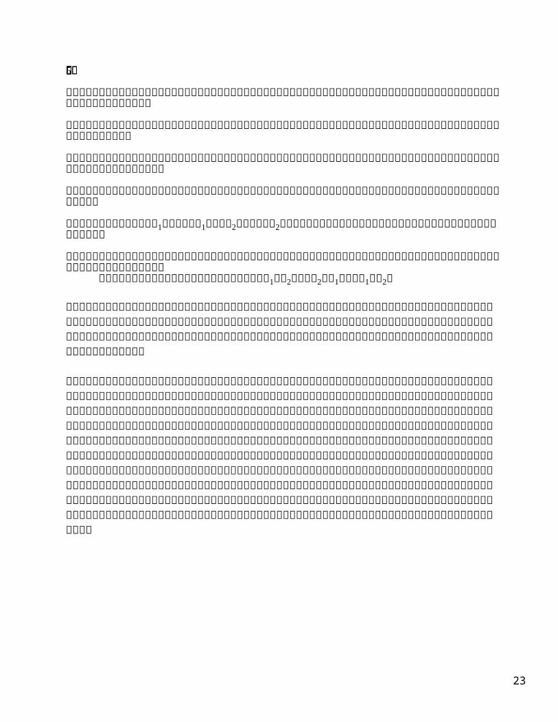
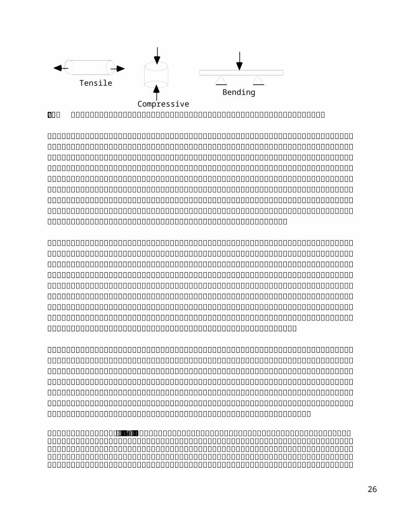
TensileBending
Compressive
22
23
Electrical Properties:
The electrical properties of ceramic materials vary greatly, with characteristic measures spanning over many orders of magnitude (see Table 3). Ceramics are probably best known as electrical insulators. Some ceramic insulators (such as BaTiO3) can be polarized and used as capacitors. Other ceramics conduct electrons when a threshold energy is reached, and are thus called semiconductors. In 1986, a new class of ceramics was discovered, the high Tc superconductors. These materials conduct electricity with essentially zero resistance. Finally, ceramics known as piezoelectrics can generate an electrical response to a mechanical force or vice versa. Table 3: Electrical Resistivity of different materials.
Type Material Resistivity (Ω-cm)Metallic conductors: Copper 1.7 x 10⁻⁶
CuO2 3 x 10⁻⁵Semiconductors: SiC 10
Germanium 40Insulators: Fire-clay brick 108
Si3N4 >1014Polystyrene 1018
Superconductors: YBa2Cu3O7-x <10-22 (below Tc)
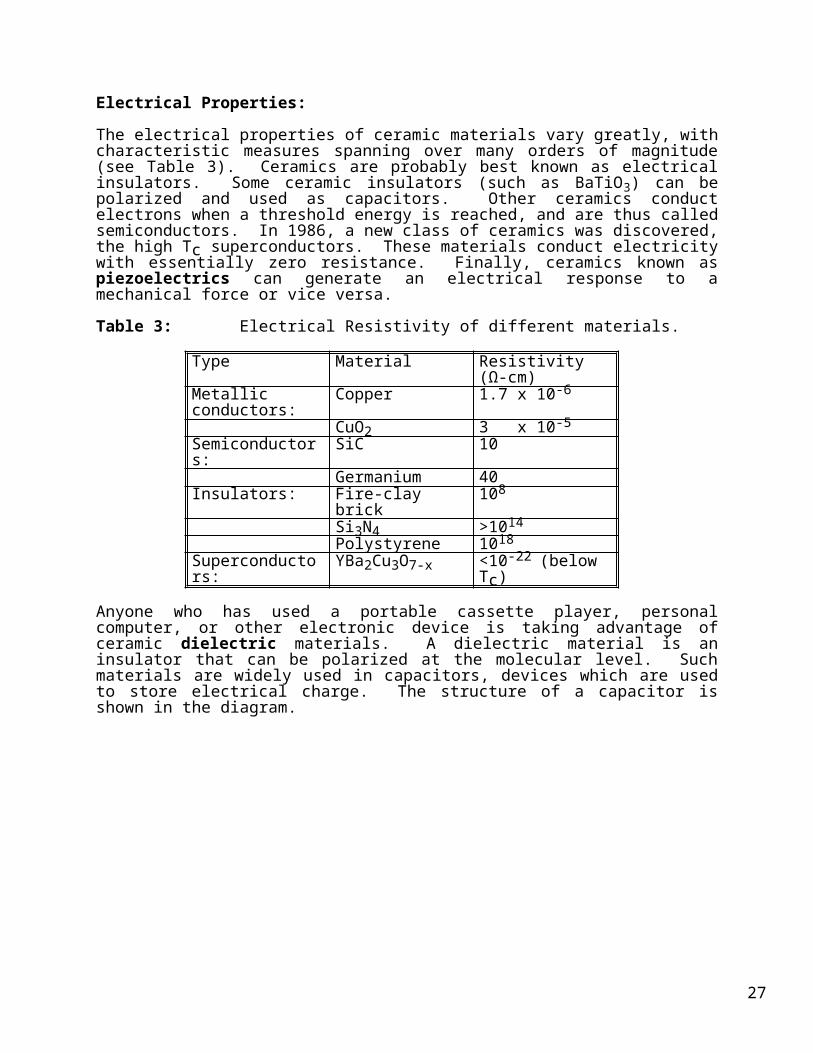
Anyone who has used a portable cassette player, personal computer, or other electronic device is taking advantage of ceramic dielectric materials. A dielectric material is an insulator that can be polarized at the molecular level. Such materials are widely used in capacitors, devices which are used to store electrical charge. The structure of a capacitor is shown in the diagram.
charge -q
capacitorplates
charge +q
externalbattery
V
- - - - - -- - - - -
+ + + + ++ + + + +
The charge of the capacitor is stored between its two plates. The amount of charge (q) that it can hold depends on its voltage (V) and its capacitance (C).
q = CV
24
The dielectric is inserted between the plates of a capacitor, raising the capacitance of the system by a factor equal to its dielectric constant, k.
q = (kC)V
Using materials that have large dielectric constants allows large amounts of charge to be stored on extremely small capacitors. This is a significant contribution to the continuing miniaturization of electronics (e.g., lap top computers, portable CD players, cellular phones, even hearing aids!).
The dielectric strength of a material is its ability to continuously hold electrons at a high voltage. When a capacitor is fully charged, there is virtually no current passing through it. But sometimes very strong electric fields (high voltages) excite large numbers of electrons from the valence band into the conduction band. When this happens current flows through the dielectric and some of the stored charge is lost. This may be accompanied by partial breakdown of the material by melting, burning, and/or vaporization. The magnetic field strength necessary to produce breakdown of a material is its dielectric strength. Some ceramic materials have extremely high dielectric strengths. For example, electrical porcelain can handle up to 300 volts for every .001 inches (mil) of the material!
Table 4: Electrical property constants of different ceramic materials.
Material Dielectric constantat 1 MHz
Dielectric strength (kV/cm)
Air 1.00059 30Polystyrene 2.54 - 2.56 240Glass (Pyrex) 5.6 142Alumina 4.5 - 8.4 16 - 63Porcelain 6.0 - 8.0 16 - 157Titanium dioxide 14 - 110 39 - 83
Electrical current in solids is most often the result of the flow of electrons (electronic conduction). In metals, mobile, conducting electrons are scattered by thermal vibrations (phonons), and this scattering is observed as resistance. Thus, in metals, resistivity increases as temperature increases.
In contrast, valence electrons in ceramic materials are usually not in the conduction band, thus most ceramics are considered insulators. However, conductivity can be increased by doping the material with impurities. Thermal energy will also promote electrons into the conduction band, so that in ceramics, conductivity increases (and resistivity decreases) as temperature increases.
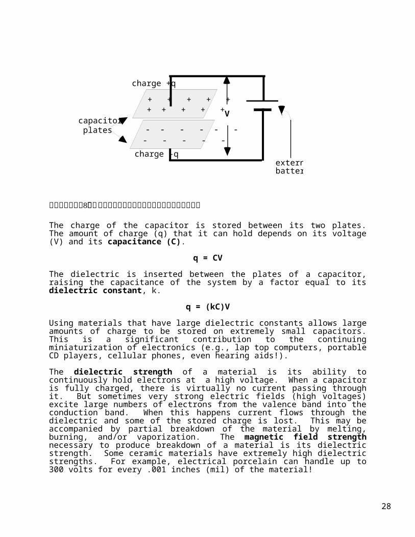
Although ceramics were historically thought of as insulating materials, ceramic superconductors were discovered in 1986. A superconductor can transmit electrical current with no resistance or power loss. For most materials, resistivity gradually decreases as temperature decreases. Superconductors have a critical temperature, Tc, at which the resistivity drops sharply to virtually zero.
25
Temperature (K)Tc
superconductors
nonsuperconductorsElectrical Resistivity
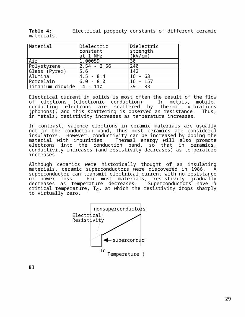
Pure metals and metal alloys were the first known superconductors. All had critical temperatures at or below 30K and required cooling with liquid helium. The new ceramic superconductors usually contain copper oxide planes such as YBa2Cu3O7 discovered in 1987 with Tc = 93 K. They have critical temperatures above the boiling point of liquid nitrogen (77.4 K), which makes many potential applications of superconductors much more practical. This is due to the lower cost of liquid nitrogen and the easier design of cryogenic devices.
CopperOxygen
Yttrium
Barium
In addition to their critical temperature, two other parameters define the region where a ceramic material is superconducting: 1) the critical current and 2) the critical magnetic field. As long as the conditions are within the critical parameters of temperature, current, and magnetic field, the material behaves as a superconductor. If any of these values is exceeded, superconductivity is destroyed.
26
Applications of superconductors which rely on their current carrying ability include electrical power generation, storage and distribution. SQUIDS (Superconducting Quantum Interference Devices) are electronic devices that use superconductors as sensitive detectors of electromagnetic radiation. Possible applications in the field of medicine include the development of advanced MRI (Magnetic Resonance Imaging) units based on magnets made of superconducting coils.
The magnetic applications of superconductors are also of major importance. Superconductors are perfect diamagnets, meaning that they will repel magnetic fields. This exclusion of an applied magnetic field is called the Meissner effect and is the basis for the proposed use of superconductors to magnetically levitate trains.
Some ceramics have the unusual property of piezoelectricity, or pressure electricity. These are part of a class known as "smart" materials which are often used as sensors. In a piezoelectric material, the application of a force or pressure on its surface induces polarization and establishes an electric field, i.e., it changes a mechanical pressure into an electrical impulse. Piezoelectric materials are used to make transducers, which are found in such common devices as phonograph pickups, depth finders, microphones, and various types of sensors.
In ceramic materials, electric charge can also be transported by ions. This property can be tailored by means of the chemical composition, and is the basis for many commercial applications. These range from chemical sensors to large scale electric power generators. One of the most prominent technologies is that of fuel cells. It is based on the ability of certain ceramics to permit the passage of oxygen anions, while at the same time being electronic insulators. Zirconia (ZrO2), stabilized with calcia (CaO), is an example of such a solid electrolyte.
Fuel cells were first used in spacecraft such as the Apollo capsules and the space shuttle. At night the fuel cells were used to generate electric power, by combusting hydrogen and oxygen from gas cylinders. During the day, solar cells took over, and the excess power was used to purify and reclaim oxygen from exhaust gas and the atmosphere exhaled by the astronauts. The lambda probe in the exhaust manifold of cars works on the same principle and is used to monitor engine efficiency.
27
Ceramic Processing:
Processing of ceramic materials describes the way in which ceramic objects (e.g., glass windows, turbocharger rotor blades, optical fibers, capacitors) are produced.
Processing begins with the raw materials needed to produce the finished components, and includes many individual steps that differ significantly depending on the type of ceramic material, crystalline versus glass.
Processing of Crystalline Ceramics Glass ProcessingRaw Material Selection Raw Material SelectionPreparation MeltingConsolidation PouringSintering Annealing
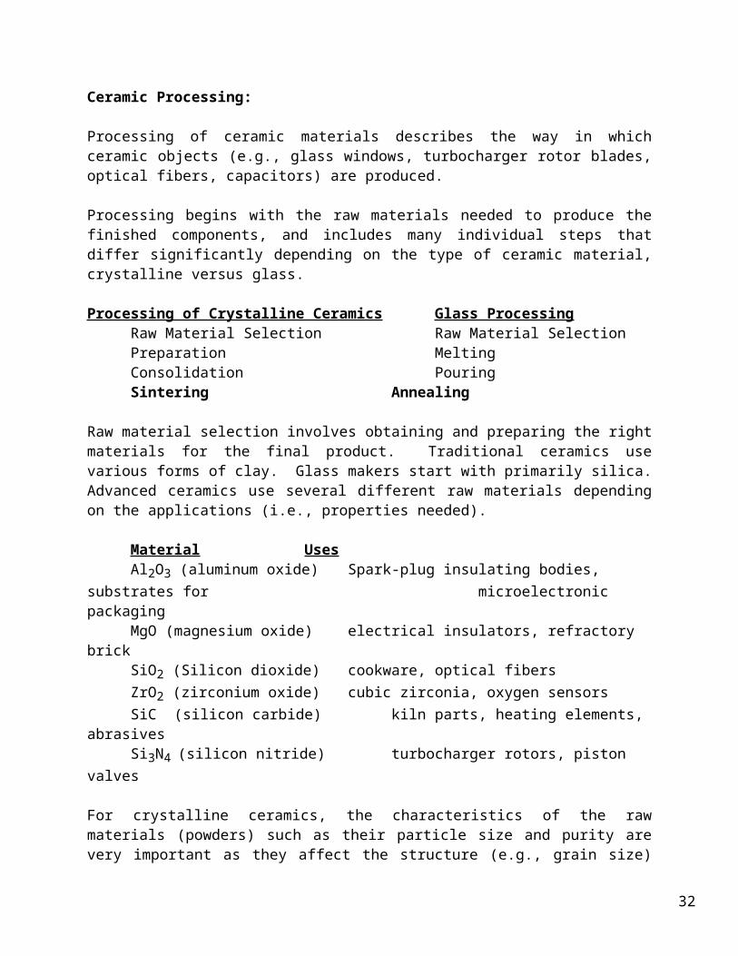
Raw material selection involves obtaining and preparing the right materials for the final product. Traditional ceramics use various forms of clay. Glass makers start with primarily silica. Advanced ceramics use several different raw materials depending on the applications (i.e., properties needed).
Material UsesAl2O3 (aluminum oxide) Spark-plug insulating bodies, substrates for
microelectronic packagingMgO (magnesium oxide) electrical insulators, refractory brickSiO2 (Silicon dioxide) cookware, optical fibersZrO2 (zirconium oxide) cubic zirconia, oxygen sensorsSiC (silicon carbide) kiln parts, heating elements, abrasivesSi3N4 (silicon nitride) turbocharger rotors, piston valves
For crystalline ceramics, the characteristics of the raw materials (powders) such as their particle size and purity are very important as they affect the structure (e.g., grain size) and properties (e.g., strength) of the final component. Since strength increases with decreasing grain size, most starting powders are milled (or ground) to produce a fine powder (diameter < 1 µm). Since dry powders are difficult to shape, processing additives like water, polymers, etc. are added to improve their plasticity.
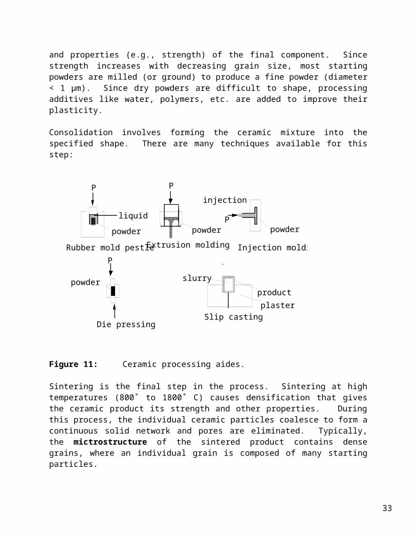
Consolidation involves forming the ceramic mixture into the specified shape. There are many techniques available for this step:
28
Die pressing
powder
P
Extrusion molding
powder
P
Injection molding
powderP
injection
slurry
productplaster
Slip casting
Rubber mold pestle
powder
liquid
P
Figure 11: Ceramic processing aides.
Sintering is the final step in the process. Sintering at high temperatures (800˚ to 1800˚ C) causes densification that gives the ceramic product its strength and other properties. During this process, the individual ceramic particles coalesce to form a continuous solid network and pores are eliminated. Typically, the mictrostructure of the sintered product contains dense grains, where an individual grain is composed of many starting particles.
forming sintering
Raw powder Formed product Sintered product
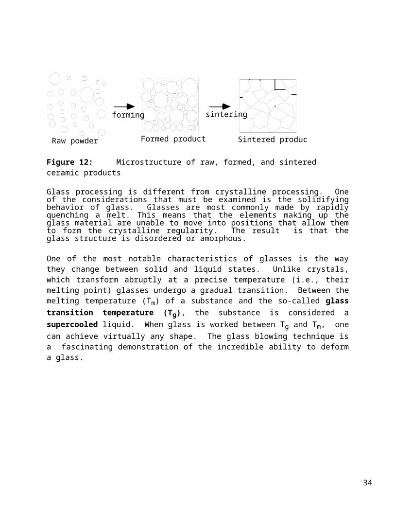
Figure 12: Microstructure of raw, formed, and sintered ceramic products
Glass processing is different from crystalline processing. One of the considerations that must be examined is the solidifying behavior of glass. Glasses are most commonly made by rapidly quenching a melt. This means that the elements making up the glass material are unable to move into positions that allow them to form the crystalline regularity. The result is that the glass structure is disordered or amorphous.
29
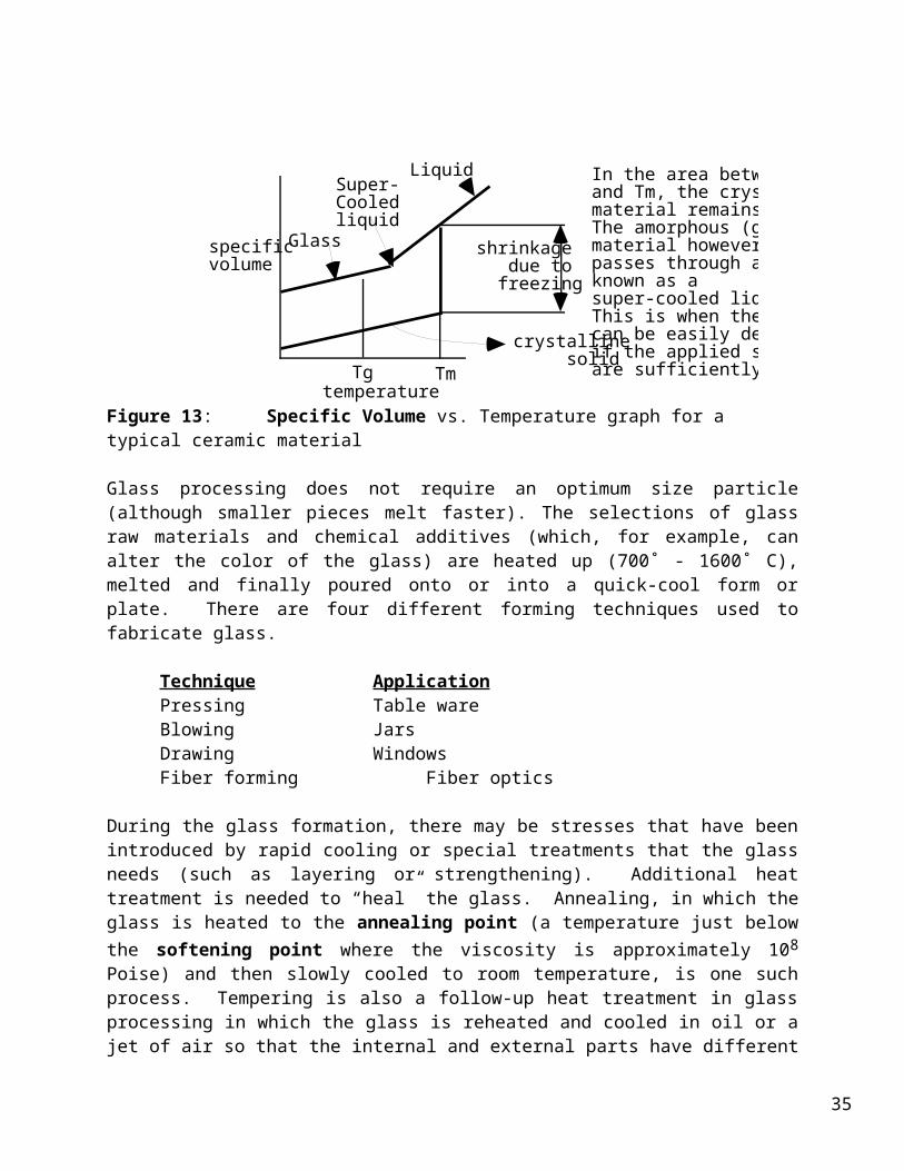
One of the most notable characteristics of glasses is the way they change between solid and liquid states. Unlike crystals, which transform abruptly at a precise temperature (i.e., their melting point) glasses undergo a gradual transition. Between the melting temperature (Tm) of a substance and the so-called glass transition temperature (Tg), the substance is considered a supercooled liquid. When glass is worked between Tg and Tm, one can achieve virtually any shape. The glass blowing technique is a fascinating demonstration of the incredible ability to deform a glass.
temperature
specific volume
Glass
Tg Tm
Super-Cooledliquid
shrinkage due to freezing
crystalline solid
Liquid In the area between Tg and Tm, the crystalline material remains solid. The amorphous (glass) material however, passes through a phase known as a super-cooled liquid. This is when the glass can be easily deformed if the applied stresses are sufficiently high.
Figure 13: Specific Volume vs. Temperature graph for a typical ceramic material
Glass processing does not require an optimum size particle (although smaller pieces melt faster). The selections of glass raw materials and chemical additives (which, for example, can alter the color of the glass) are heated up (700˚ - 1600˚ C), melted and finally poured onto or into a quick-cool form or plate. There are four different forming techniques used to fabricate glass.
Technique ApplicationPressing Table wareBlowing JarsDrawing WindowsFiber forming Fiber optics
During the glass formation, there may be stresses that have been introduced by rapid cooling or special treatments that the glass needs (such as layering or strengthening). Additional heat treatment is needed to “heal” the glass. Annealing, in which the glass is heated to the annealing point (a temperature just below the softening point where the viscosity is approximately 108
Poise) and then slowly cooled to room temperature, is one such process. Tempering is also a follow-up heat treatment in glass processing in which the glass is reheated and cooled in oil or a jet of air so that the internal and external parts have different properties. The tempering reduces the tendency of glass to fail. Tempered glass can then be used in conditions prone to stresses like car windows.
30
31
32
References
Baker,W. et al., Synthetic Materials: Applications in Biology/Chemistry, Center for Occupational Research and Development, Waco, TX (1993).
Buchanan, R. (editor),"Electronic Ceramics," Ceramic Bulletin, 63:4 (1984) pp. 567-594.
Callister, W. D., Materials Science and Engineering, an Introduction, John Wiley and Sons, NY (1994).
Chandler, M., Ceramics in the Modern World, Double Day & Co. Inc., Garden City, NY(1967).
Ellis, A. B. et al.,Teaching General Chemistry: A Materials Science Companion, American Chemical Society, Washington, D.C. (1993).
Evans, J. & DeJonghe, L.C,The Production of Inorganic Materials, Macmillan Publishing Company, NY (1991).
Halliday, D. & Resnick, R., Physics, John Wiley and Sons, NY (1978).
Hench, L., "Bioceramics: from Concept to Clinic," American Ceramic Society Bulletin, 72:4 (April 1993) pp. 93-98.
Hlavac, J., Technology of Glass and Ceramics, Elsevier Scientific Press, Oxford (1983).
Holscher, H. H., "Hollow and Specialty Glass: Background and Challenge," Owens- Illinois Bulletin, reprinted from The Glass Industry, Vol. 46, Glass Publishing Co., NY (1965).
Hove, J. E. and Riley,W. C., Modern Ceramics, John Wiley and Sons, NY (1965).
Ichinose, Noboru, Introduction to Fine Ceramics, John Wiley and Sons, NY (1987).
Kendall, K., "Ceramics in Fuel Cells," Ceramic Bulletin, 70:7 (1991) pp. 1159-1160.
Ketron, L. A., "Fiber Optics: The Ultimate Communications Media," Ceramic Bulletin, 66:11 (1987) pp. 1571-1578.
Kingery, W. D., Bowen, H. K., Uhlmann, D. R., Introduction to Ceramics, John Wiley and Sons, NY (1976).
Kingery, W. D., The Changing Roles of Ceramics in Society, American Ceramic Society, Westerville, OH (1990).
Korb, L. J., et al., "The Shuttle Orbiter Thermal Protection System," Bulletin American Ceramic Society, 60:11 (1981) pp. 1188-1193.
33
Lewis, J., "Superconductivity: Conventional vs. High Tc Superconductors," unpublished University of Illinois at Urbana Champaign, MAST workshop.
Mitchell, Lane, Ceramics: Stone Age to Space Age, McGraw-Hill, Inc., NY (1963).
Musicant, Solomon, What Every Engineer Should Know about Ceramics, Marcel Dekker, Inc., NY (1991).
Norton, F. H., Elements of Ceramics, Addison-Wesley, Cambridge, MA (1952).
Orna, M. V., Schreck, J. O., & Heikkinen, H., ChemSource. Vol. 2, ChemSource, Inc. New Rochelle, NY (1994).
Reed, James., Principles of Ceramic Processing, John Wiley and Sons, NY (1988).
Rhodes, D.,Clay and Glazes for the Potter, Clinton Book Co., Radnor, PA (1974).
Richerson, D. W., Modern Ceramic Engineering, Marcel Dekker, Inc., NY (1982).
Scholes, S. R., Modern Glass Practice, Industrial Publications, NY (1952).
Schwartz, M. M. (editor), Engineering Applications of Ceramic Materials, American Society for Metals, Metals Park, OH (1985).
Sheppard, L. M., "Automotive Performance Accelerates with Ceramics," CeramicBulletin, 69:6 (1990) pp. 1011-1021.
Sheppard, L. M., "Automotive Sensors Improve Driving Performance," Ceramic Bulletin, 71:6 (1992) pp. 905-912.
Smith,W. F., Foundations of Material Science and Engineering, McGraw Hill, Inc. (1993).
Tipler, P., Physics, Worth Publishers, Inc. (1982).
Viechnicki, D. J., Slavin, M. J., & Kliman, M. I., "Development and Current Status of Armor Ceramics," Ceramic Bulletin, 70:6 (1991) pp. 1035-1039.
Vincenzini, P., Fundamentals of Ceramic Engineering, Elsevier Applied Science, NY (1991).
Weast, R. C. (editor), CRC Handbook of Chemistry and Physics, CRC Press, Inc. Boca Raton, FL (1985).
Wellock and Deckman, Ceramic Bulletin, Vol. 71, No. 1. (1992).
Resources
34
ALCOA : 1-800-643-8771
American Ceramic Society 735 Ceramic PlaceWesterville, OH 43081-8720614-890-4700
35
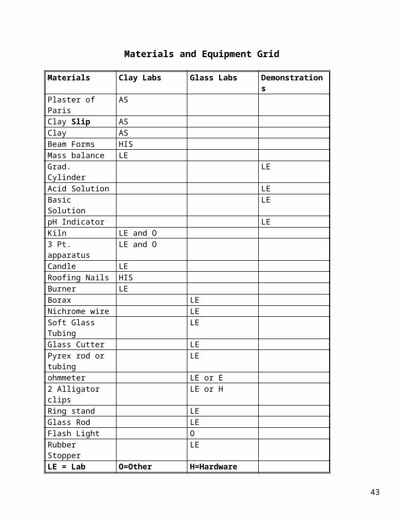
Materials and Equipment Grid
Materials Clay Labs Glass Labs DemonstrationsPlaster of Paris ASClay Slip ASClay AS Beam Forms HISMass balance LEGrad. Cylinder LEAcid Solution LEBasic Solution LEpH Indicator LEKiln LE and O3 Pt. apparatus LE and OCandle LERoofing Nails HISBurner LEBorax LE Nichrome wire LESoft Glass Tubing LEGlass Cutter LEPyrex rod or tubing LEohmmeter LE or E2 Alligator clips LE or HRing stand LEGlass Rod LEFlash Light ORubber Stopper LELE = Lab equipment
O=OtherAS=Art supply store
H=HardwareE=Electronic store
36
Experiment 1
Ready-Beam-Fire
Clay Labs
Objective:
To compare mechanical and thermal properties of fired and unfired beams made from art clay and clay suspensions (slip).
Review of Scientific Principles:
Clay was the first ceramic material used by humans, and it continues to be useful in modern times. Clays used for pottery are composed mainly of hydrated silica (SiO2) and alumina (Al2O3). Small amounts of other minerals (Fe2O3, MgO, etc.) are typically present.
Clay is somewhat unique in its ability to be plastically formed (shaped) when wet. This plasticity depends on the amount of water, the size and shape of the particles, ionic content, and temperature.
Clay slip is made by mixing clay with water to make a mixture that can be poured into a mold. This method, called slip casting, is used to make thin, detailed products. Plaster of Paris is commonly used to make the molds because it is inexpensive, easy to work with, and highly porous (easily absorbing water from the cast slip).
Clay objects must be allowed to dry before firing to eliminate most of the pore water. The remaining pore water is eliminated during the initial stage of firing at around 100˚C.
Firing and sintering change the properties of the object significantly. At about 350˚C the water of hydration is driven off. As the temperature increases into the sintering stage, the porosity changes from an open to closed network; and the object shrinks as porosity is eliminated. This leads to increased density and improved mechanical strength. The fired product is hard, dense, more durable, impermeable to liquids, and brittle. This activity investigates the relationships between mechanical strength, density (porosity), and thermal conductivity of unfired and fired clay objects.
Applications:
The slip casting method is used to make a variety of ceramic objects (e.g., clay-based dishes, kitchen and bath fixtures, as well as silicon nitride (Si3N4) turbocharger rotor blades). It is useful for three-dimensional complex objects with uniform wall thicknesses less than two centimeters.
Time:
This lab takes several days (6) to go from preparation to testing.
37

Part A (make molds): 1/2 hour first dayPart B (make beams and fire): 1/2 hour second day to make a set of beams of each
type, 3 days for clay slip to air dry before firing Firing time varies
Part C (Test beams): Testing four beams requires about 20 minutes for each test
38
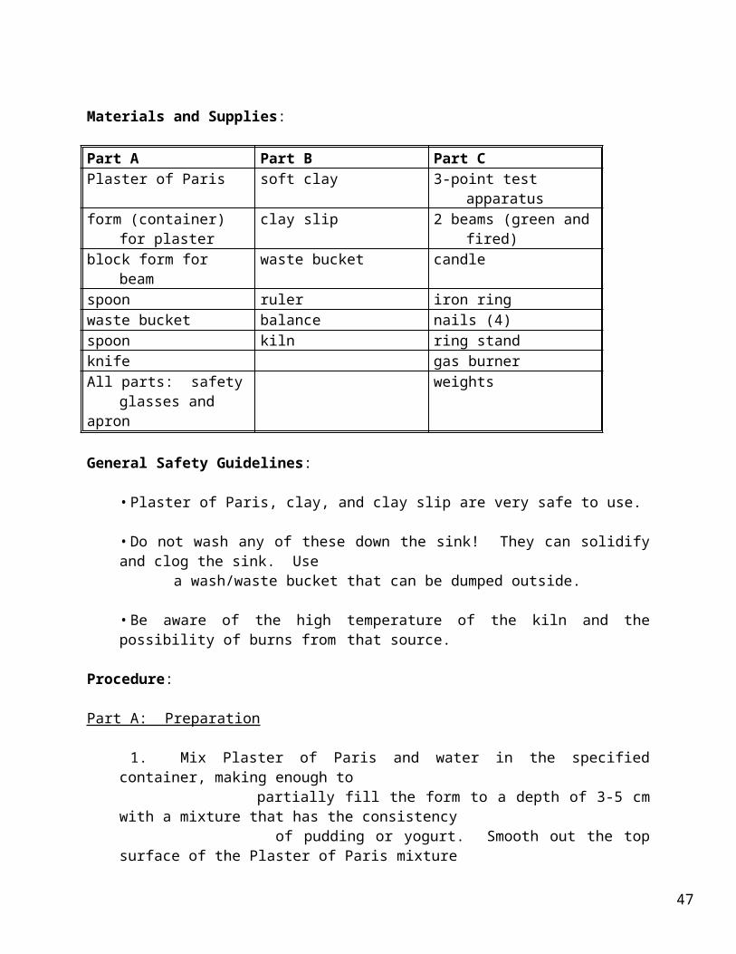
Materials and Supplies:
Part A Part B Part CPlaster of Paris soft clay 3-point test apparatusform (container) for plaster clay slip 2 beams (green and fired)block form for beam waste bucket candlespoon ruler iron ringwaste bucket balance nails (4)spoon kiln ring standknife gas burnerAll parts: safety glasses
andapron
weights
General Safety Guidelines:
• Plaster of Paris, clay, and clay slip are very safe to use.
• Do not wash any of these down the sink! They can solidify and clog the sink. Use a wash/waste bucket that can be dumped outside.
• Be aware of the high temperature of the kiln and the possibility of burns from that source.
Procedure:
Part A: Preparation
1. Mix Plaster of Paris and water in the specified container, making enough to partially fill the form to a depth of 3-5 cm with a mixture that has the consistency of pudding or yogurt. Smooth out the top surface of the Plaster of Paris mixture by tapping the mixture on the table. Work quickly. You have less than five minutes after adding the water before solidification sets in.
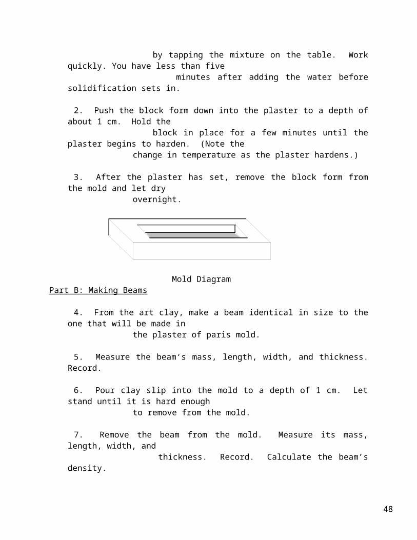
2. Push the block form down into the plaster to a depth of about 1 cm. Hold the block in place for a few minutes until the plaster begins to harden. (Note the change in temperature as the plaster hardens.)
3. After the plaster has set, remove the block form from the mold and let dry overnight.
39

Mold DiagramPart B: Making Beams
4. From the art clay, make a beam identical in size to the one that will be made in the plaster of paris mold.
5. Measure the beam‘s mass, length, width, and thickness. Record.
6. Pour clay slip into the mold to a depth of 1 cm. Let stand until it is hard enough to remove from the mold.
7. Remove the beam from the mold. Measure its mass, length, width, and thickness. Record. Calculate the beam’s density.
8. Allow the beams to dry for at least three days before firing. Before the firing is done, measure the mass and dimensions of the beam. Calculate the density of the beam.
will explain how the firing will be done.
Part C. Testing Of Beams
10. Before testing, measure the mass and dimensions of each beam. Calculate the 10. Before testing, measure the mass and dimensions of each beam. Calculate the density of the beam.
11. To test for the thermal properties of your beam, use a lit candle to drip wax on the beam. Attach four nails equally distributed along the side of the beam. Set
the beam on a ring stand. Heat one end of a beam with a gas burner. Time how fast the heat travels down the beam by watching the objects fall when the heat reaches them. Record the times.
12. To test mechanical properties, place the beam to be tested across the supports. Attach any equipment needed for the testing apparatus.
13. Attach a container and add mass until the beam gives way.
14. Measure the added weight . Calculate the force that broke the beam.
15. Clean up as directed by instructor.
40
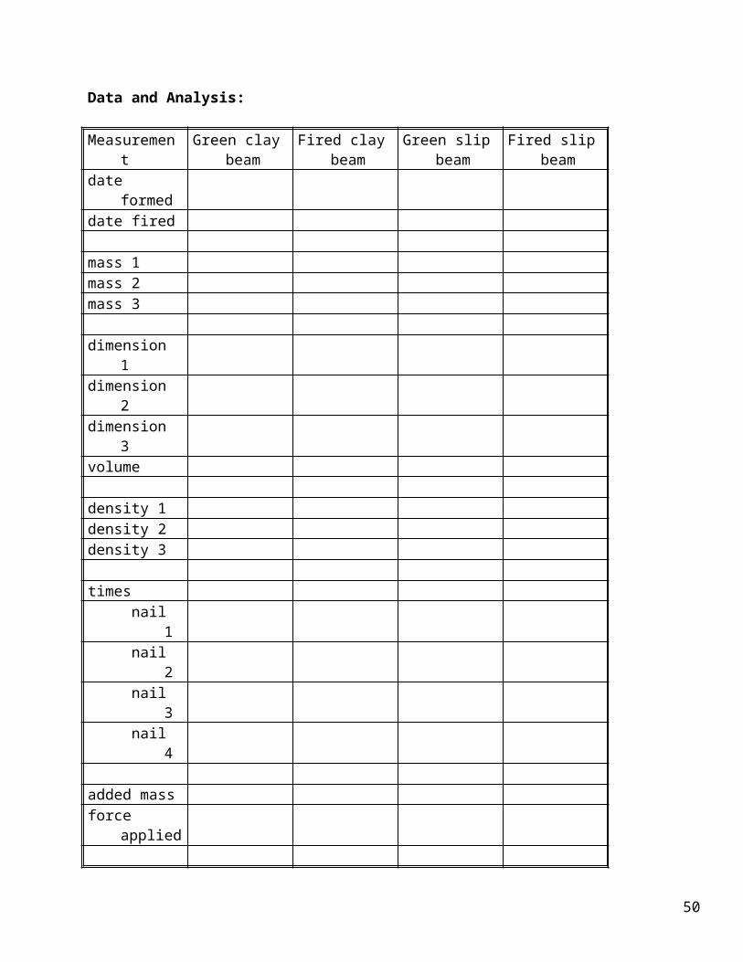
Data and Analysis:
Measurement Green clay beam
Fired clay beam Green slip beam
Fired slip beam
date formeddate fired
mass 1mass 2mass 3
dimension 1dimension 2dimension 3volume
density 1density 2density 3
timesnail 1nail 2nail 3nail 4
added massforce applied
Questions:
1. What is accomplished by firing that is not accomplished by simple drying?
2. What might happen if the beam were fired before it dried?
3. How is strength different from hardness?
4. Summarize the differences in density, mechanical and thermal properties between the fired and unfired beams as observed in this lab.
41
5. Palette, the art teacher, fires an assortment of ceramics. What might happen if the firing temperature was too low? What if it was too high ?
42
Teacher's Guide to Experiment #1Clay Labs
Consult the art teacher or ceramics craft shop for firing times.
Materials and Supplies:
•Plaster of Paris may be purchased at some hardware stores. Soft clay (such as is used on a potter's wheel) is available in art supply stores. Do not use the plastic, nonbaking type of clay. Clay slip is available from ceramic craft shops. Both clay and clay slip can be purchased from American Art Clay Co., 4717 W. Sixteenth St.,
Indianapolis, IN 46209-2292.
•It is recommended that lab tables be covered with plastic or newspaper to simplify clean up.
•A three-point apparatus is designed to support the beams at the ends while applying a force in the middle. This apparatus can be a simple as 2 desks to support
the beams and a rope loop in the middle on which to hang weights or a bucket to hold weight.
•A second class lever system could also be set up.
Procedure:
•This procedure is written for each student group to produce one Plaster of Paris mold, one formed clay beam, and one poured clay slip beam. If done this way, two groups will have to work together in Part C with one set of beams having been fired and the other set left green. It is important that all beams be nearly the same size. If variations are desired, adjust time and quantities of materials used.
A-1 •Plaster of Paris may be mixed in mold form or in a separate container and then poured into the mold.
A-2 •The block could be removed shortly after the Plaster of Paris begins to set, or it could be left in the form until the next day.
•A piece of 2" x 2" or 2" x 4" lumber or 1" x 2" firing strips or a plastic form can be used as a block form. These could be marked with a line at 1 cm to get consistency in depth among the student groups. If other objects are used to press into the plaster,
they may need a light coating of oil to prevent them from sticking to the plaster.
B-4: •There are a couple of ways that this can be done. One is to press clay into the mold, smooth, and pull out a beam. You may have to run a knife around the edge to help remove the beam. Or the block form could be used as a template to cut a beam from a slab cut off the stock clay (try to cut off slabs to just the right thickness) or rolled to the right thickness. Test tubes or graduated cylinders make nice rolling pins.
43

B-6: •This might be about 30 minutes or more. The poured beam could also be left in the mold until the next day .
B-7: •Students are instructed to find the density through mass and linear measurements of the beams when they are first made, after air drying, and after firing. Additional measurements could be added to get a more detailed picture of the changes that occur
during these processes.
B-9: •If a large ceramic kiln is used, it may take 20 minutes to load the class items into the kiln and several hours to bring the kiln up to temperature and then overnight for it to cool back down. If a small enameling kiln is used, the process may take only an hour or so.
•It helps if the beams are prewarmed and dried at about 200oF in a regular oven for 2 to 4 hours before firing.
•The beams to be fired are to be dried, either for several days in a warm dry place or several hours in a drying oven at 100oC.
•Put the object in a kiln and the raise the temperature slowly until the maximum temperature called for is reached and held for several hours.
•Turn the kiln off and allow it to cool before opening. If a ceramic kiln is not available, it is possible to use an electric hot plate with an 8 inch clay flowerpot lined
with aluminum foil and inverted on the plate. This small kiln will give a temperature around 1300oF. This really works!
C-12: •If the 2nd class lever system is being used, then measure the basic down force by hooking a spring balance to the end of the lever arm. If a bucket on a rope is being used, make sure they are the same for each test group or record the different masses.
C-14: • If a second class lever was used, add the basic force of the lever arm and this is your effort force. Multiple this force by the IMA (Ideal Mechanical Advantage) of the machine. You will have the force that was needed to break the beam.
•You may want to do a 3-point test or thermal lab on other materials like glass (Pyrex), plastic, and metals for a materials comparison.
Answers to Questions:
1. Firing fuses the particles together.
2. The water that was still in the pores might cause the beam to break.
3. Strength is the ability to resist deformation, hardness is the ability to resist
44
abrasion.
4. Answers will vary. Basically unfired beams are more dense, less thermally conductive, and weaker than fired beams.
5. Too Low - objects would crumble. Too high - objects would be melted down like glass.
45

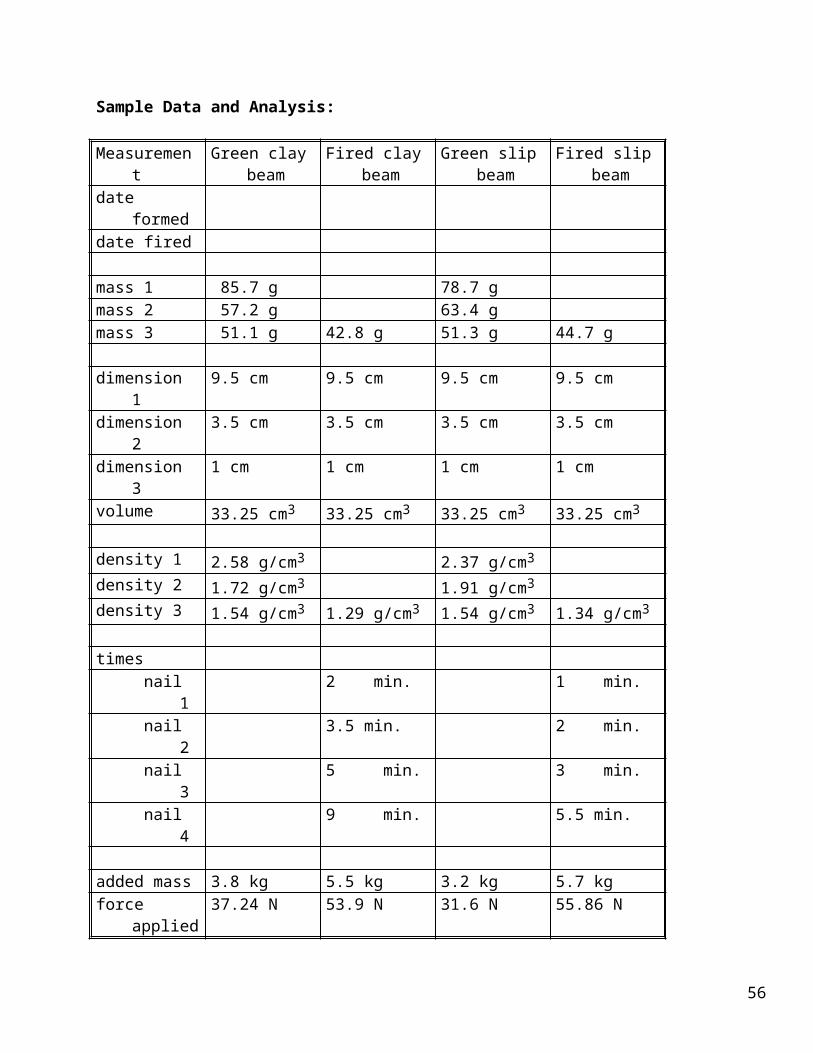
Sample Data and Analysis:
Measurement Green clay beam
Fired clay beam Green slip beam
Fired slip beam
date formeddate fired
mass 1 85.7 g 78.7 gmass 2 57.2 g 63.4 gmass 3 51.1 g 42.8 g 51.3 g 44.7 g
dimension 1 9.5 cm 9.5 cm 9.5 cm 9.5 cmdimension 2 3.5 cm 3.5 cm 3.5 cm 3.5 cmdimension 3 1 cm 1 cm 1 cm 1 cmvolume 33.25 cm3 33.25 cm3 33.25 cm3 33.25 cm3
density 1 2.58 g/cm3 2.37 g/cm3
density 2 1.72 g/cm3 1.91 g/cm3
density 3 1.54 g/cm3 1.29 g/cm3 1.54 g/cm3 1.34 g/cm3
timesnail 1 2 min. 1 min.nail 2 3.5 min. 2 min.nail 3 5 min. 3 min.nail 4 9 min. 5.5 min.
added mass 3.8 kg 5.5 kg 3.2 kg 5.7 kgforce applied 37.24 N 53.9 N 31.6 N 55.86 N
46
Experiment 2 (Demonstration) Flocculation
In School Suspensions
Flocculation in ceramics
Objective:
The objective of this demonstration is to show the effect the pH on the flocculation of suspensions.
Review of Scientific Principles:
The process of forming a ceramic object usually involves filling a form (mold) with a ceramic suspension (such as clay). The suspension will gradually settle out due to gravity. It is important in ceramic processing to have the particles settle out individually to achieve the closest packing of the particles because the strength of a ceramic is partially determined by its density. The rate of settling depends on the size of the particle (big particles or particle clusters settle faster) and the charge that may be on the particles in solution. The charge on each particle may repel the other particles and keep the material in suspension, or it may cause the particles to be attracted to each other and form clusters (or Flocs) which settle faster. By adjusting the pH of the solution, ceramic processors can control the degree of flocculation (settling out) of the ceramic particles and thus control the properties of the product. The chemicals that control flocculation are called deflocculating agents.
This demonstration shows the effect of pH on the flocculation of a clay suspension.
Applications:
Understanding how chemistry influences suspension structure is important in numerous fields, such as ceramics, paint industry, even food products.
Time:
Fifteen minutes to set up and run.
Materials and Supplies:
Slipdistilled wateracidic, neutral and basic solutions 100 ml. graduated cylinders (3)
General Safety Guidelines:
47
•The acidic and basic solutions are corrosive and should be handled with care. Use a dump bucket for ceramic materials.
48
Procedure:
1. Measure out the slip to equal a 10% volume of the graduated cylinder.
2. Fill each graduated cylinder with a different pH solution.
3. Shake well. Take measurements of volume of settled material over a period of time.
49
Experiment 3
Wow you can see right through me!!!
Glass Labs
Objectives:
The objectives of this lab are to form a low temperature glass, work with glass blowing and explore the conductive nature of glass.
Review of Scientific Principles:
Glasses are amorphous ceramic materials. The amorphous (or glassy) state of matter occurs when a substance has not been given sufficient time to crystallize. Glasses are most commonly made by rapidly quenching a melt. This means that the atoms making up the glass material are unable to move into positions which allow them to form the crystalline regularity. This may be attributed to the fact that each atom is strongly bonded to adjacent atoms while in the liquid state, and that the crystalline structures are very complex. The end result of all these factors is that the glass structure is disordered and therefore amorphous.
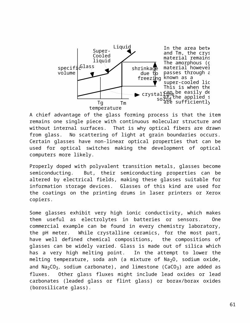
One of the most notable characteristics of glasses is the way they change between solid and liquid states. Unlike crystals, which transform abruptly at a precise temperature (i.e., their melting point) glasses undergo a gradual transition. Between the melting temperature (Tm) of a substance and the so-called glass transition temperature (Tg), the substance is considered a supercooled liquid. When glass is worked between Tg and Tm, one can achieve virtually any shape. The glass blowing technique is a fascinating demonstration of the incredible ability of glass to deform.
temperature
specific volume
Glass
Tg Tm
Super-Cooledliquid
shrinkage due to freezing
crystalline solid
Liquid In the area between Tg and Tm, the crystalline material remains solid. The amorphous (glass) material however, passes through a phase known as a super-cooled liquid. This is when the glass can be easily deformed if the applied stresses are sufficiently high.
A chief advantage of the glass forming process is that the item remains one single piece with continuous molecular structure and without internal surfaces. That is why optical fibers are drawn from glass. No scattering of light at grain boundaries occurs. Certain glasses have non-
50
linear optical properties that can be used for optical switches making the development of optical computers more likely.
Properly doped with polyvalent transition metals, glasses become semiconducting. But, their semiconducting properties can be altered by electrical fields, making these glasses suitable for information storage devices. Glasses of this kind are used for the coatings on the printing drums in laser printers or Xerox copiers.
Some glasses exhibit very high ionic conductivity, which makes them useful as electrolytes in batteries or sensors. One commercial example can be found in every chemistry laboratory, the pH meter. While crystalline ceramics, for the most part, have well defined chemical compositions, the compositions of glasses can be widely varied. Glass is made out of silica which has a very high melting point. In the attempt to lower the melting temperature, soda ash (a mixture of Na2O, sodium oxide, and Na2CO3, sodium carbonate), and limestone (CaCO3) are added as fluxes. Other glass fluxes might include lead oxides or lead carbonates (leaded glass or flint glass) or borax/borax oxides (borosilicate glass).
Borax is a naturally occurring mineral that is chemically hydrated sodium borate or Na2B4O7 . 10 H2O. The material is a white powder that is sold in super markets as a laundry aid. Borax is also used as a flux in working some metals because it coats and cleans the metal and allows soldering to take place. When Borax is heated, the water of hydration is driven off and the sodium, boron and oxygen form a non-crystalline glass. This glass is clear but will take a color from the various metal oxides such as cobalt or nickel. Thus the Borax beads can be used to identify some metal ions as well as demonstrate materials used to make colored glass. Borax Glass is also unstable in that it tends to absorb moisture from the air and revert back to a cloudy hydrated material.
This activity demonstrates the formation of a borax-based glass, the technique of glass blowing, and the electrical conduction properties of glass.
Time:
Part A: 20- 50 minutesPart B: 40 minutesPart C: 30 minutes
Materials and Supplies: Part A: 3 inch piece of nichrome wire
a small quantity of borax (0.5g) sodium tetraborate Gas burner
Part B: lime or lead glass tubing (7 to 10 mm in diameter about 20 to 25 cm long) 2-3 cm rubber tube to fit glass tubing gas burner
glass filePart C: piece of lime glass rod or tubing (5 to 10 mm diameter )
piece of Pyrex (5-10 mm diameter)
51
ohmmeter2 alligator clipshook up wirecandlering standiron ring gas burner
General Safety Guidelines:
• Nichrome is not a good conductor so you can hold one end of a 3 inch wire but remember, the other end is at 500 - 700˚ C .
• Remember, you will be using a gas burner. Perform this lab using all fire cautions.
• Hot glass and cold glass look the same. Be careful to check for hot glass.
• The glass bead will drip off if too large and it will be hot.
• The cool glass could break from the wire with very sharp edges.
Procedure:
Part A: Borax Glass 1. Obtain the nichrome wire and make a loop with a diameter of about 0.5 cm at one end.
2. Heat the loop over the Bunsen burner until the wire is red hot.
3. Dip the hot loop into the Borax powder.
4. Hold the loop with the powder stuck to it in the flame until the Borax becomes a clear, glassy drop. (Approximate time will vary depending on the temperature of the flame and the amount of Borax on the wire.). Add extra Borax if necessary by redipping the wire into the Borax.
5. With the Borax glass still in the wire, allow it to cool. After it has cooled, examine it.
6. Check the solubility of your “glass” by leaving it, still in the wire, in some water overnight.
Part B: Glass Blowing
Bud Vase Procedure:
52
1. Preheat the glass tubing end by passing it back and forth in the flame.
2. Heat the end until it melts closed. Keep rotating the tube for even heating and to keep the glass from drooping.
3. When the end is very hot and completely closed, blow gently into the tube, watching the end at all times. When the bubble is about three times the diameter of the tubing, stop blowing. Cool the tube with the bubble.
4. When cool, cut the tubing about 2 inches from the bubble and fire polish the open end. Do not melt close. Allow the object to cool.*
*You now have a bud vase that will hold one rose bud or some other special flower from a special date. Some ribbon and a hot glue gun will dress it up. Have Fun but Play Safe.
Part C: Electrical Conductivity
1. Using the smoking flame from a candle, deposit two rings of carbon around a cool glass rod The rings should be about three centimeters apart.
2. Clamp an alligator clip to each of the carbon rings.
3. Attach the other end of the leads from the alligator clip to the ohmmeter
4. Clamp the glass rod so that it can be heated.
5. Heat the glass rod and record the electrical resistance every ten seconds.
6. Continue to heat until the glass softens, continue to record resistance
7. On a sheet of graph paper, plot resistance on the vertical axis and time on the horizontal axis.
Data and Analysis:
TIMEStart10 Seconds20 Seconds30 Seconds40 Seconds50 Seconds60 Seconds70 Seconds80 Seconds
53
90 Seconds
Questions:
Part A:
1. How is this glass like window glass? How is it different?
2. You are commissioned to make a mosaic picture of a rainbow using borax glass. What metal ions would you use for the colors?
Part B:
1. Why do professional glass blowers like Pyrex glass?
2. Why does glass just get soft and not melt suddenly and become a liquid?
Part C:
1. Why do different types of glass show different degrees of electrical conductivity?
2. If glass will conduct electricity under certain conditions, do you think it might conduct at room temperature if the voltage is high enough?
3. Do you think the distance between the alligator clips on the glass rod has any effect on the resistance? Why or why not?
4. What does this experiment tell you about the need to control temperatures in electronic devices like computers?
54
Teacher's Guide to Experiment #3Glass Labs
Materials:
•Borax obtained from grocery stores may not work for this lab as some contain detergents or soaps).
General Safety Guidelines:
•Use a wire that is a poor conductor of heat and nonreactive at elevated temperatures. Handles could be added to the nichrome wire.
Procedure:
A-6: •If the “glass“ comes out clear enough, you may suggest that they try to use them like a magnifying glass.
•If you want to, have them try a Borax Bead Test, either new wires will have to be handed out or have them make a new loop on the other end of the wire.
Extension to Part B:
This is a procedure for making a glass swan. With lots of patience and practice, you or your students might want to try this.
Swan Procedure:
1. Place rubber tubing on one end of the glass tubing.
2. Light and adjust burner for a hot flame.
3. Preheat the center of the glass tube and then heat strongly while rotating the tube.
4. As the glass softens, gently push the tubing together just a little. (This allows extra glass for a strong bubble.)
5. Pinch the rubber tube and blow into the glass end until there is a bubble about twice the size of the tubing diameter.
6. While the glass is still hot, make the bubble shape not round by pushing both ends of the tubing at an angle, about 140 degrees relative to each other.
7. Heat either tube near the bubble (body), when soft push the tube back over the bubble (body) to make the neck of the swan. DO NOT HEAT THE BUBBLE
55
(BODY).
8. Leave a section of the tube, a centimeter or so, at the end of the neck to form the head and heat the tube at this point. (This will make the beak.)
9. When the glass is soft pull it and melt it off.
10. Gently heat the bottom of the bubble (body) with the side of the flame. (This
part of the bubble will then become flat.)
11. Holding the glass by the beak and the other end of the tube, preheat the tail area. (The tube opposite from the beak.) DO NOT HEAT THE BUBBLE
(BODY).
12. When the glass is soft, pull upward and gently twist to form the tail.
13. Melt off excess glass tube and allow to cool.
14. HOW DO YOU MAKE A GOOD ONE ? THE SAME WAY YOU GET TO CARNEGIE HALL .... PRACTICE, PRACTICE, PRACTICE.
Part C Suggestions:
•You might have to seal a piece of Nichrome wire into each end of a 3 cm piece of glass tubing and use this.
•You may want different teams to try different materials such as Pyrex glass, lime glass, leaded glass and or different diameters of the same material. How about other
ceramic materials?
•You may also want them to continue recording every 10 seconds while the glass cools and include that data in their graph.
•Electrical resistance should go from more than 20 megaohms at room temperature down to less than one megaohm at 700˚ C.
Sample Data and Analysis: Pyrex Tube
Time Electrical Resistance Start 20 MΩ
10 seconds 15.72 MΩ20 seconds 7.23 MΩ30 seconds 4.05 MΩ40 seconds 2.30 MΩ50 seconds 1.07 MΩ60 seconds 0.54 MΩ
56
70 seconds 0.073 MΩheat removed80 seconds 0.23 MΩ90 seconds 0.95 MΩ100 seconds 1.85 MΩ110 seconds 3.17 MΩ120 seconds 8.22 MΩ130 seconds 14.78 MΩ140 seconds 20+ MΩ
Sample Graph:
Answers:
Part A:
1. The glass is transparent and hard but not stable.
2. Answers will vary. Consult CRC Borax Bead Tests Table.
Part B:
1. Pyrex is tough and is heat resistant.
2. Glass is a mixture and does not exhibit long rang crystal structure.
Part C:
57
1. Different amounts and types of ionic and covalent bonds effect the degree of electrical conductivity.
2. Yes, at high voltages glass will conduct. A Tesla coil will show this or some adult toy like the plasma storm ball sold by stores.
3. Yes. It is analogous to resistance in wire. Resistance is directly proportional to the length and inversely proportional to the diameter.
4. Electronic devices need to be kept within their designated temperature range to operate as expected.
58
Experiment 4 (Demonstration) Electrical Resistance
How many teachers does it take to break a light bulb?
Electrical Resistance in a Glass Bulb
Materials and Supplies:
six volt flashlight bulbceramic base for lightohmmeter2 alligator clips with wiresgas burner
Procedure: 1. Screw the 6 volt light bulb into a miniature ceramic light socket.
2. Break away the glass surrounding the filament.
3. Cut the filament that connects the two electrodes in the bulb.
4. Carefully remove the filament and do not damage the small glass bead that connects both electrodes just below the filament.
5. Hook the ohmmeter to the contacts on the base of the ceramic light socket.
6. Gently heat the glass bead while recording the resistance.
7. Record the resistance and time at 10 second intervals (if possible).
59
Experiment 5
Light at the End of the Tunnel
An Introduction to the Study of Fiber Optics
Objective:
The objective of this experiment is to show that, because of internal reflection, light will travel down a glass tube.
Review of Scientific Principles:
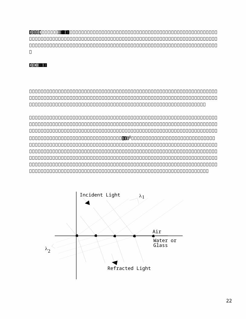
Being a noncrystalline material, glass does not have grain boundaries to interfere with the passage of photons (light bundles). As long as the light waves hit the inside walls at less that the critical angle (the minimum angle that will allow light to be transmitted into the glass), most of the light will reflect off the side walls and continue through the tube.
As the angle of incidence increases, the angle of refraction increases, until the critical angle is reached. At this point the angle of refraction is equal to 90 degrees, and total reflection occurs.
90
Criticalangle
Angle ofIncidence
Partial refractionAngle of
refraction
Total reflection
Partial reflection
AirGlass
The rods in a fiber optic system use a core inside a clad design. The core is made of a high purity glass with a larger refractive index than the outer layer. (A refractive index is a measure of the amount that light bends going into or out of a material.) The greater the difference in the refractive indices, the more light is reflected within the inner tube.
60
core
clad
Light Wave
Fiber Optic Tube
Most fiber optic systems use a laser as the light source due to its coherency and the fact that it can be controlled with high frequency pulses. The light pulses sent from one end of the fiber optic cable, are received and decoded at the other end to obtain the original information.
Applications:
Much of the data sent over today’s communication networks is being carried by light pulses moving through fiber optics.
Time: 20 minutes
Materials and Supplies:
glass rod ( 5 mm +/- diameter; 15-20 cm long)gas burnersmall penlight flashlightone hole rubber stopper to fit flashlight
General Safety Guidelines:
• Be aware of the fire and hot glass.
• Be extra careful when preforming the glass insertion.
Procedure:
1. Light burner and preheat the center of the glass rod until it gets soft.
2. Slowly bend the rod so that no bend has a radius of less than 2 cm. Make a continuous glass bend of your choosing. Avoid making sharp corners during bending.
61
2 cmmax radius
Rubber Stopper
3. Cool. Carefully insert one end of your rod into a one-holed rubber stopper. Put the stopper on the end of the flashlight.
4. Turn on the flashlight and observe the amount of light coming through the rod and the amount of light leaking out along the rod.
5. If time permits, try different radii in the curves. If you have access to a laser, try it in the tube as well.
Questions:
1. What did you observe from shining the flashlight through the tubing?
2. What advantage does a laser have in this experiment over a flashlight?
3. Why was it necessary to form bends with at least a 2 cm radius?
62
Teacher's Guide to Experiment # 5Light Lab
Suggestion:
You might want to conduct the tests in a darkened room.
Answers to Questions:
1. Students should report most of the light exiting the other end of the tube. Only a small fraction of the light will come out the sides of the tube.
2. The laser light can be aimed along a straight line down the tube. The light from the flashlight will spread out and some will exceed the critical angle and escape out the side of the tube.
3. At smaller radii, the light will strike the walls of the tube at angles greater than the critical angle.
63
Ceramics Module Quiz
Short answer.1. What made ceramics the first technology?
2. What are the two general classes of ceramics and how are they different?
3. What advantages and disadvantages do ceramics have over other materials?
4. What general properties do ionic materials have?
5. What general properties do covalent materials have?
6. What general properties do ceramic materials have?
7. Why are ceramics brittle and most metals not?
8. Why is glass transparent but a brick is not?
9. What causes thermal expansion in materials, and why do ceramic materials have small coefficients of expansion?
64
10. List the parts of your body that are ceramic materials. How do you know that they are?
Ceramics Module Quiz Answers
1. Natural materials were available and so was fire.
2. Crystalline - regular structure and Noncrystalline (amorphous)-irregular structure. or Traditional-clay, cement & glass and Advanced-newer high strength, high temperature materials.
3. Advantages: hard, temperature resistance, corrosion resistance, inexpensive. Disadvantages: brittle and hard to machine.
4. Ionic - tend to have high melting points & nondirectional strong bonds.
5. Covalent - tend to have lower melting points and weak bonds.
6. Ceramics have high melting points, tend to be brittle and have both ionic and covalent bonds.
7. In ceramic materials, the atoms are not free to move under stress as they are in metals.
8. In glass, the lower energy bonding orbitals (valence band) and the higher energy antibonding orbitals (conduction band) are different enough so that visible light is not absorbed.
9. As the temperature increases, the vibrational amplitude increases for atoms in a material which drives that atoms apart. In ceramics the bonds are stronger between atoms which counteracts the tendency to expand.
10. Bones and teeth - hard, brittle and temperature resistant.
65
GLOSSARY
Abrasive: A hard material used to grind, cut or wear.Absorption: The inclusion of the energy of a photon within a substance.Amorphous: A noncrystalline substance, atoms lack long range order.Annealing: Heat treatment to alter properties.Annealing point (glass): Temperature at which stresses are removed.Atomic vibration: Movement of an atom within a substance.Band gap energy: Energy difference between the valence and conduction bands.Brittle fracture: A break that occurs by rapid crack propagation.Capacitance (C): Charge storing capability.Cement: A material that binds particles together in a mixture.Ceramic: A compound of metallic and nonmetallic elements.Color: Wavelengths of light perceived by the eye.Component: A part, or device.Conduction band: Carries the excited conduction electrons.Conductivity: The ability to carry an electric current (electricity) or thermal energy (heat).Covalent bond: Bonding by sharing electrons.Crystalline: A solid with a repeating three-dimensional unit cell.Crystal structure: The orderly arrangement of the atoms or ions within a crystal.Diamagnetism: Weakly repelled from a magnetic field.Dielectric: An insulator.Dielectric constant: Relative electrical permittivity of a material as compared to a perfect
vacuum.Dielectric (breakdown) strength: The amount of electricity needed to start an electric current flow in a dielectric material.Ductile fracture: Break accompanied by large plastic deformation.Elastic deformation: Change in shape that returns when a stress is removed.Elastic Modulus: Ratio of stress to strain in elastic deformation, measure of elasticity.Electric field: The gradient of voltage.Electronegativity: The attraction of an atom for shared electrons.Electron volt (eV): Unit of energy equivalent to the energy gained by an electron when it falls through an electric potential of one volt.Excited state: An energy state to which an electron may move by the absorption of energy.Fiber Optics: The technology of transferring information as light pulses through long thin fibers, usually made of glass. Firing: High temperature processing to increase densification in a product.Fluorescence: Light that is emitted a short period of time after an electron has been
excited.Fracture toughness (Kc): Measure of a material's resistance to crack propagation.Glass: An amorphous solid showing characteristic specific volume behavior over a certain temperature range.Glass - ceramic: Crystalline ceramic material that was formed by heat treating glass.Glass transition temperature (Tg): Temperature at which a glass changes from a
supercooled liquid into a solid.Grain: Individual crystal in a polycrystalline material.
66
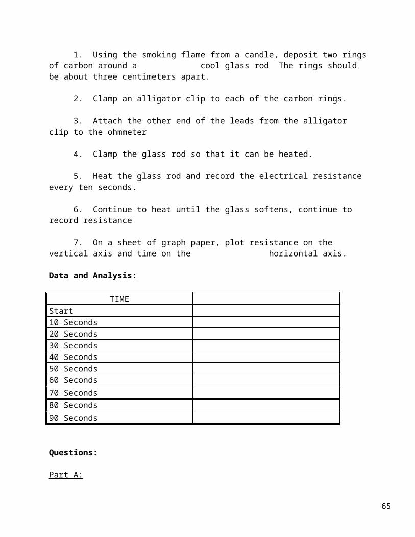
Grain boundary: The boundary between grains (or crystals) that are misoriented with respect to one another. Green ceramic body: Ceramic object that is dried but not fired.Ground state: Lowest electron energy state.Hardness: Resistance to deformation.Heat capacity: Heat required to produce a unit increase in temperature per quantity of
material.Imperfection: Flaw, any deviation from perfection, as in a crystal.Index of refraction: Ratio of the speed of light in a vacuum to the speed of light in a
medium.Insulator: Material that does not conduct electricity (electrical) or heat (thermal).Ionic bond: Electrostatic force between oppositely charged ions.Laser: Source of coherent light (Light Amplification by Stimulated Emission of Radiation).Lattice: The regular arrangement of points in a crystal.Luminescence: Emission of visible light when an electron returns to the ground state from an excited state.Magnetic field strength: Intensity of an applied magnetic field.Microstructure: Structural features that can be observed with a microscope.Noncrystalline: Amorphous, with no long-range atomic order.Opaque: Material that does not transmit light.Phonon: Quantum of vibrational energy.Phosphorescence: Luminescence that lasts for more than one second.Photovoltaic cells: A device capable of converting light energy to electricity.Photoconductivity: Electrical conductivity induced by light.Photon: Quantum of electromagnetic energy.Piezoelectric: Material that produces an electrical response to a mechanical force.Plastic deformation: Permanent deformation, change of shape.Polycrystalline: Composed of more than one crystal or grain.Porcelain: A durable ceramic composite made by firing clay, feldspar and quartz
together.Reflection: Deflection of light at the interface between two materials.Refraction: Bending of light as it passes from one medium into another.Refractory: Material that can be exposed to high temperature without deterioration.Resistivity: Measure of resistance to passage of electrical current (reciprocal of conductivity).Semiconductor: Nonmetallic material that has a relatively narrow energy band gap.Sintering: Coalescence of individual ceramic particles into a continuous solid phase at a
high temperature. Slip: Mixture of clay with water that can be poured into a mold.Slip casting: Method of making ceramic objects by pouring slip into a mold.Softening point (glass): Maximum temperature a glass can be heated before it permanently deforms.Smart materials: Materials able to detect a change in the environment and react to it.Specific volume: Volume per unit mass, reciprocal of density.Strain: Change in length of a sample in the direction of an applied stress.Stress: Force applied to a sample divided by its cross-sectional area.Structural clay products: Ceramic objects made mainly of clay and used in structural applications.Structure: Arrangement of internal components.
67
Superconductivity: Disappearance of electrical resistivity at low temperatures.Supercooling: Cooling below the normal temperature for a phase change, without the change occurring.Tensile strength: Maximum stress without fracture.Thermal expansion coefficient, linear: Fractional change in length divided by change in temperature, a measure of a materials tendency to expand when heated.Thermal stress: Residual stress caused by a change in temperature.Thermal tempering: The introduction of residual compressive stresses to increase the
strength of glass.Toughness: Energy absorbed by a material as it fractures, a measure of its resistance to
fracture.Transgranular fracture: Fracture by crack propagation through the grains.Translucent: Transmits light diffusely.Transparent: Transmits light clearly.Unit cell: The basic repeating unit in a crystal.Whiteware: Clay-based ceramic that turns white after firing.
68