Embed Size (px)
Citation preview

Www.ceramicafans.com
Ceramica Introduction
Creating a New Concept
Our motto
In 1990, was brought forth by a simple idea -
Over the years we continued to adhere to this customer oriented approach and built our
expertise in the field of thermal management.
Today, has grown into an international organization of
We are
Ceramica is the premier expert in production and distribution of a wide range of:
Cooling fans
Cooling components
Thermal management solutions
Ceramica is dedicated to provide our customers with
High Quality products at competitive prices.
Excellent service
Good delivery time frame
Ceramica
Ceramica
“The Ceramic Bearing Fan”
�
�
�
�
�
�
Creating a better more affordable fan.
cooling solution research and
development, design, manufacture, and marketing conglomerates.
the proud inventor and sole maker of the most reliable fan
At Ceramica we strive to be the leaders in our field, and hope that
by the turn of century, we have evolved into one of the leading
companies in fan cooling. Ceramica continues to uphold the
proud traditions that lead to today's success.

www.ceramicafans.comwww.ceramicafans.com
A New Era for Cooling Fan
Having Problems With Noise and Life Span? This is the Fan You Need!
New Industry Demands
Switching to Ceramics
Retrospecting to the history we should be able to realize the amazing impact of new materials in various
fields of applications. The discovery of semiconductor brought forth the era of electronic industry, and led
the change of our life style. The development of heat resistant materials like engineering ceramics broke
the power and life limits of traditional engines for jets and autos. Today, through our R&D efforts,
Ceramica proudly announces the successful development of ceramic bearing system for mini cooling fan
applications, a breakthrough for fans and a new thoughts for the fan industry.
Noise and life span have been two major issues when using fans as your cooling solution.
Because noise, especially abnormal noise, can be annoying and fidgety; and the life span can be a
direct problem with the performance and reliability of your system. The major reason being its bearing.
However Ceramica have solved this problem with their new Ceramic bearing system.
We always try to satisfy our customers demands. We have been striving to solve the noise and life
problems of conventional cooling fans. The development of Ceramica fans is your solution! Patented
technology utilizes the improved ZrO2 engineering ceramics for the bearing system. ZrO2 engineering
ceramics has the advantages of wear, heat and chemical resistant. It can be shaped and machined
precisely and easily. Owing to its superior material characteristics, this type of bearing system has
passed CSIST's rigorous test, which showed extended life compared to existing fans. Ceramica fans
have been well accepted by our customers since their introduction at the end of 2001. The application of
new technology changes your thoughts, and it is the future in fan application.
Five years ago, Ceramica realized that the IT industry was posing new demands on fan
Makers, and the company began to develop its own technology, taking advantage of the properties of
ceramic materials.
Ceramic Bearing System

www.ceramicafans.com
After years of research and development, Ceramica launched its first generation of ceramic bearing
systems, featuring a ceramic shaft and a high-precision alloy sleeve bearing. This arrangement proved to
offer much better quality than a copper sleeve bearing. The ceramic shaft is very precisely machined,
with a very fine surface texture, well in advance of the traditional steel shaft.
Ceramica launched it's A series fans late in 2001, and this year the company plans to launch its C series,
which feature a combination of ceramic shaft and ceramic sleeve. This combination offers very durable
and smooth operation, at the same or slightly less cost than a two-bearing system,
while keeping its noise level to a minimum.
For Ceramica, the ceramic design approach has been a success, with a very positive market response,
and increase in sales turnover. More design companies are turning to this ceramic technology as
ceramic materials offer many advantages, some of which include being durable and resistant to heat
and humidity."
believes ball bearing type fans are no longer the best fan solution.
Through years of research and development, we have found the following advantages of the
ceramic bearing type over the current two ball bearing type fan:
Provides alternative to traditional bearing system
Provides equivalent or better life expectancy
Provides equivalent or better reliability
Provides Cost effective solution
Increase the yield rate of fan production
have evolved to the stage where diversified design of microstructures and
attributes are within the power of engineer and designers. Varying its control of composition, fabrication
route, thermal treatment and final machining, Zirconia has provided hundreds of successful cases in
replacing traditional materials as robust and cost effective solutions.
High hardness
Greater wear resistance
Low thermal expansion
Low conductivity
Chemical Inertness
Good for precision machining
�
�
Reduced complexity of fan assembly compared to traditional fans
Improved fan structure to reduce noise from bearing system
�
�
�
�
�
�
�
�
�
�
�
Why Ceramic Bearing
The Advantages of Zirconia Based Ceramics
Ceramica R&D
Zirconia based ceramics

Ceramica Improved Ceramics
Ceramica’s Manufacturing Processes
Ceramica is always seeking for better ways to develop its materials. The processes developed from
raw material, molding,
Sintering to final machining have gone through a trial and error period until the final ceramic
bearing was perfected. This process was as follows:
Employing the state-of-the-art nano technology
Partially Stabilized Zirconia (PSZ), which well disperses the
tetragonal preci-pitates within cubic morphology
The transformation toughened zirconia is characterized by high strength
and fracture toughness Precision injection molding for forming
Good for creating finely polished surfaces
Ceramica has its full capability from forming to final machining. The raw material is made by
deliberately mixing all the necessary ingredients with ceramic powder of less than 300 nano for molding.
Precision injection molding process is developed to make ceramic shafts and bearing of various shapes
and dimensions. The debinding and sintering processes are then followed to make the final shape and
the characteristics needed. The two processes are finely controlled such that all the binders are removed
with great precession while microstructure and the grain size can be produced and Maintained for best
strength and hardness. In addition, the perfect combination of molding and sintering processes makes
the need of machining to a minimum. This is achieved by the “near-net-shape” technology such that there
is no excess ceramic material to be machined and therefore the post machining process can be
conducted in a very productive way.
�
�
�
�
www.ceramicafans.com
Ceramica

Upon the completion of the pre-forming process, the shaft and bearing are moved forward for post
machining process. Various machining processes are employed depending on the functional need of
each part designed. Either the need to make the dimension, the geometry or the required surface
texture can be achieved.
The Microstructure of Ceramica Ceramic Material with Magnification
Of x 15000, x 5000 and x 1000
www.ceramicafans.com
FORMING MACHINING
KKnneeaaddiinngg
II nnjjeeccttiioonn MMoollddiinngg
DDee--bbiinnddiinngg
SSiinntteerr iinngg
GGrriinnddiinngg
HHoonniinngg
LLaappppiinngg
FFaacciinngg
CChhaammffeerriinngg
Ceramica Ceramic Manufacturing Processes

Ceramica’s Ceramics Research and Inspection
Ceramica ceramic products have gone thorough investigation from different perspectives.
The ceramic laboratory and quality control are equipped with necessary high precision instruments for
verifying the properties and characteristics of the material made and parts produced.
These high precision instruments are capable of checking and reflecting the quality of the products from
material and machining aspects, such as the microstructure, strength, hardness, roundness,
roughness, etc.
The most important factors and parameters to be examined
are listed in the table for your reference.
www.ceramicafans.com

www.ceramicafans.com
Ceramica A Series
The “A” series fans were introduced a few years ago. Its bearing system features a well machined and
polished ceramic shaft along with a fine alloy sleeve. The ceramic shaft possesses adequate hardness
that results in very high wear resistance. The surface of the shaft is machined and polished ,
Reflecting a smooth and shiny texture that conventional SUS shaft can not match . Not only
can this hard and fine surface preserve its original quality for an Extreme long period of time of operation,
it also comes with the run-in polishing effect on the alloy sleeve.
(next page) shows the surface of the ceramic shaft before any operation, and the surface
of the ceramic shaft after an extended period of operation under high temperature (acceleration test).
It can easily be seen how durable the ceramic shaft is, by its low ware characteristics after a long
operational period.
(Figure 1)
(Figure 2)
Figure 3 and 4
Figure 3 The ceramic shaft after 8,000 hoursof operation in 70 C test environment, comparedto the traditional steel shaft after 1500 hours ofoperation under the same condition
o
Figure 1 Shows the fine surface ofthe ceramic shaft as well as themeasured surface roughness.
Figure 2 Shows the surface of theSUS steel shaft as well as themeasured surface roughness

www.ceramicafans.com
(Figure 5)
(Figure 6)
The comparison roughness measurement of a ceramic shaft versus a traditional steel shaft.
Shows the ware factor of the sleeve between the ceramic shaft versus the metal type. The
perfect match of the ceramic shaft and the alloy sleeve results in a very smooth and quite operation, with
exceptionally long service life expectancy. Ceramica A series is, in its essence, different from traditional
bearing systems in many perspectives, from material characteristics, processes to precision. A complete
comparison can be found on table “A”. Currently the Ceramica “A” series fan ranges from 25 mm to 120
mm, both in axial and centrifugal. It has been applied to different fields of market segments, such as IT,
telecom, industry, auto, and home appliances, etc.
Figure 4. Roughness measurement of ceramicshaft after 8,000 hours of operation in 70 C testenvironment versus the traditional steel shaft after 1500hours of operation under the same condition
o
Figure 6 The inner surface of the alloy sleevebefore operation and the inner surface of thealloy sleeve after 8,000 hours of operation in70 C test environment, showing a run-in polishingeffect by ceramic shaft
o
Figure 5 the roundness measurement of ceramicshaft after 8,000 hours of operation in 70 C testenvironment and the traditional steel shaft after1500 hours of operation under the same condition
o

www.ceramicafans.com
Ceramica C Series
After further research and development, Ceramica launches C fan series in year 2004, featuring a
precisely machined ceramic shaft and ceramic bearing. By best using the advantages of the ceramic
material and well defined tolerance and precision, Ceramica C series out performs most of the current
existing bearing systems in many aspects such as in operation stability, noise, service life, etc.
shows the surface characteristics of the shaft before and after 12000 hours of high temperature operation
test. Note that the shaft is the same as what is used for A Series. show the surface
characteristics and the roundness of the ceramic bearing under the same test condition as the shaft. Due
to the precision and the advantages of the material, Ceramica C series results in an even more reliable
performance. Furthermore, the patented design of the bearing makes this high-end application more cost
effective.
Figure 7
Figure 8 and 9
Figure 7 The surface of the ceramic shaftbefore and after 12,000 hours of operationat 70 C test environment
o

Figure 8 The surface and the roughnessmeasurement of the ceramic bearing beforeand after 12,000 hours of operation at 70 Ctest environment
o
Figure 9 The roundness measurement of theceramic bearing before and after 12,000 hoursof operation at 70 C test environment
o
www.ceramicafans.com

Tab
leA
-T
he
Co
mp
aris
on
of
Tra
ditio
nalB
earin
gS
yste
ms
with
Cera
mic
aB
earin
gS
yste
m
www.ceramicafans.com
Ceram
ica
A-S
erie
sC
eram
ica
C-S
erie
s

Engineering Information
1. P - the static pressure
.
The fan static pressure is one of the key specifications required to calculate its airflow performance.
Regardless how it is measured it can be explained in the following simplified manner. Imagine that a
fan is installed at one end of an open tube in a way that the fan is drawing air from out side of the tube
(the free air) and sending the air flow into the tube . Now, let’s take a plate and cover the
other end of the tube, which will have the following results:
A. Zero air flow if we completely seal the other end of the tube with the plate .
B. We will get a little flow if we leave a small gap by slightly moving the plate
C. We will get more flow if we leave a larger opening .
D. Maximum Air flow if we completely move the plate away from the tube ..
In there is no air flow as the tube is pressurized such that the fan driving force can not
overcome the tube pressure. When the tube has a slight leak ( B) the pressure inside the
tube is lower than that of and the fan is able to expel air out of the tube. As the end plate
is moved to allow a larger opening to the other end of the tube, the lower the resistance and the easier
it is for the Fan to push the air through the tube.
Figure 11
Understanding a Fan and Its Performance
(Figure 10)
(Figure 11A)
(Figure 11B)
(Figure 11C)
(Figure 11D)
Figure 11A
Figure 11A
www.ceramicafans.com
(Figure 10) Free air is drawnthrough the tube by the fan
(Figure 1 )1 A End plate sealsthe tube, no air flow.
Tube
Tube

www.ceramicafans.com
As the end plate is fully removed, the tube pressure becomes minimum, and no resistance within the
tube. (assuming Non-viscous flow, no friction and no boundary layer closed to the wall).
Normally we use the term “static pressure” to evaluate the performance of the fan or the amount of
power to overcome the resistance given by the working environment. Maximum static pressure is the
maximum power a fan can generate. Air flow will commence when the pressure (or, the resistance) of
the working environment is lower than the fan maximum static pressure. The higher this number is,
the more capable the fan is to overcome resistance.
(Figure 1 )1 B A small opening will onlyallow a small amount of air flow.
(Figure 1 )1 C As the opening becomeslarger, the airflow is increased while theinternal resistance of the tube decreases.
P1A > P1B > P1C > P1DP0 is the ambient pressure
(Figure 1 )1 D Maximum airflow isachieved when the end plate isfully removed.

2. Q- the air flow rate
3. The meaning of P-Q curve
The air flow rate is the volume of air flow delivered by the fan per unit time. Following the scenario
described in previous section, we get the maximum air flow rate in In other words
maximum airflow because there is no “resistance” in the tube. When the end of the tube is blocked,
the internal resistance will increase, causing a pressure difference between both ends of the tube.
This can be called a “Back Thrust”, causing the fan to work harder. No airflow will be produced when
the back thrust is equal to the fan maximum pressure.
In below, the ordinate is the static pressure and the abscissa is the flow rate. The most
commonly used units for flow rate is the CFM (cubic foot per minute) and CMM (cubic meter per
minute). The counter part units for pressure are inch-H O and mmH O. From time to time you may use
units other than the said ones. is a cross reference between different units. A P-Q curve
shows, when a fan is selected and used, the maximum flow the fan can deliver (of course, under zero
static pressure situation); the maximum pressure the fan can generate to overcome the system
resistance (under zero flow rate situation); and all the possible flow rate the fan can produce between
these two extremes. Your next question is how do you know the exact fan operating point when a fan
is installed on your system? This is, in fact, a question that needs more knowledge and is not easily
answered (it will be explained in later section). Owning to this reason, most of the time engineers
select fans based on two extremes without involving themselves too much further. people are
selecting fans based on the two extremes without involving themselves too much further. It is
suggested that you try to get several fans with similar performance and make your own experiment
and select the best one based on which fan gives you the best operating point (max airflow within
the system).
2 2
Figure 11D.
Figure 12
Table 1 and 2
Figure 13A Fan A has higher pressurethan Fan B at Q*
Figure 12 An example of a P-Q curve
www.ceramicafans.com

Table 1 Conversion table of static pressure
Table 2 Conversion table of air flow rate
www.ceramicafans.com
In general terms the greater the convex, the better. For example, in curves A and B have
the same maximum flow rate (at zero pressure) and maximum pressure (at zero flow rate). However,
the fan representing curve A is much better than the fan in curve B. As the static pressure level is
much higher under the same air flow conditions Q*. Therefore Fan “A” has a higher airflow than Fan
“B” (See ). But in reality, these curves are not as simple as our illustrated waveforms. A
typical fan curve can have a curve which concaves somewhere in the middle, other times the P-Q
curve can be complex to understand and it requires good knowledge in aerodynamics. Generally the
greater the convex curve the better the performance of the fan.
The performance of a fan is reflected by the performance curve, or the so-called P-Q curve, which is
obtained by measuring the flow rate and the corresponding pressure. The measurement is done using
the double chamber method, based on AMCA standard 210 (85). This method employs a wind tunnel
with two chambers to create an environment with dissimilar pressure difference, such that
4. Measuring method and standard
Figure 13A
Figure13B
(Figure 14)
,
Figure 13B Fan A has more flow than Fan B at P* Figure 14 Double chamber wind tunnel
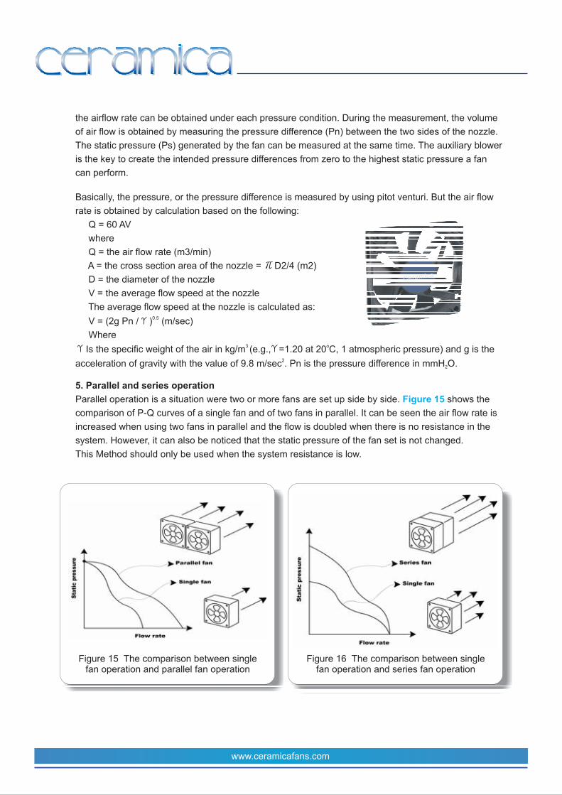
Figure 15 The comparison between singlefan operation and parallel fan operation
Figure 16 The comparison between singlefan operation and series fan operation
www.ceramicafans.com
the airflow rate can be obtained under each pressure condition. During the measurement, the volume
of air flow is obtained by measuring the pressure difference (Pn) between the two sides of the nozzle.
The static pressure (Ps) generated by the fan can be measured at the same time. The auxiliary blower
is the key to create the intended pressure differences from zero to the highest static pressure a fan
can perform.
Basically, the pressure, or the pressure difference is measured by using pitot venturi. But the air flow
rate is obtained by calculation based on the following:
Q = 60 AV
where
Q = the air flow rate (m3/min)
A = the cross section area of the nozzle = D2/4 (m2)
D = the diameter of the nozzle
V = the average flow speed at the nozzle
The average flow speed at the nozzle is calculated as:
V = (2g Pn / ) (m/sec)
Where
Is the specific weight of the air in kg/m (e.g., =1.20 at 20 C, 1 atmospheric pressure) and g is the
acceleration of gravity with the value of 9.8 m/sec . Pn is the pressure difference in mmH O.
Parallel operation is a situation were two or more fans are set up side by side. shows the
comparison of P-Q curves of a single fan and of two fans in parallel. It can be seen the air flow rate is
increased when using two fans in parallel and the flow is doubled when there is no resistance in the
system. However, it can also be noticed that the static pressure of the fan set is not changed.
This Method should only be used when the system resistance is low.
0.5
3 o
2
2
5. Parallel and series operation
Figure 15
Ceramica

Another multiple fan operation is series operation. In this case, you use two or more fans in series.
is a comparison of the performance curve of a single fan with that of two fans in series.
We can see that the static pressure of the fan series is almost doubled. However, the maximum flow
rate is not increased. Series operation can be considered when the resistance of the system is high.
Because single fan operation is not able to deliver adequate air flow for cooling. Higher static pressure
is needed to overcome the resistance of the system. Series operation is one of the options when high
static pressure is required.
Why do you need a fan? It is because you need some extra air flow to cool your system down?
Do you have still air conditions when the system is hot? No. Air is actually moving slowly due to
density difference. We call it natural convection. When the temperature of the system or key
component exceeds its limit, we need extra air flow. When this extra air flow is produced by using a
fan, we call it active cooling (achieved by forced convection). Air is a material with mass. Anything with
mass can absorb heat. As a result, the fan that can drive the amount of volume of air to prevent the
temperature of the system from reaching it limit is the bottom line choice. Any fan that can not cool
your system down enough will be ruled out for further evaluation. So the first thing you want to do is to
figure out how much air flow you need to remove the heat generated by your system.
Heat is transferred only when there is a temperature difference between the heat source (your
system) and the environment. When air flow rate is high, the temperature difference will be low,
as the air removes the heat very fast not allowing the heat to accumulate (when heat
accumulates, the temperature rises). When the air flow rate is low, the heat accumulates until it
creates a temperature difference that is adequate for another equilibrium (i.e., more “load” on the
air passed by). Therefore, in order to know the volume of air flow needed, the following points
must be known:
A. The amount of heat generated in your system
B. The temperature limit of your system and the surrounding temperature.
C. Calculate the minimum air volume required.
D. Estimate the system impedance (resistance, in terms of air flow) of your system.
E. Match the above estimate with the performance curve of the selected fan.
is a schematic expression of a system with a heat source inside. This system is to be
cooled down by using a fan. Assume the ambient temperature is T and the ceiling temperature of
the system is T . The minimum heat to be removed in order to keep the system temperature less than
Tc is calculated as:
H = Cp x M x T where
C is the specific air heat, M is the air mass and T is the temperature difference between Tc and T .
The air mass is the flow rate Q times the density ( ) of the air.
1. How much Air flow is required?
Air Volume Calculation
amb
c
p amb
Figure 16
Figure 17
Steps to Select Your Ideal Fan
▲
▲
▲
▲
www.ceramicafans.com

www.ceramicafans.com
If we rearrange the above equation we will have:
Where
Cp 1005 J/Kg C and 1.18 Kg/m3
Example. For a given heat source of 200 watts with a system enviroment that cant exceed 80 .
If air with ambient temperature of 25 is drawn from outside of the system, the air flow rate Q can
be calculated.
Before the calculation. Check Table 2 for help.
Q = 200 watts/ (1005 x 1.18 x 55) = 0.00307 (m3/s) = 0.184 CMM = 6.5 CFM
To help you further, you may use
Q H / (20 x T) for CMM (H in watt and T in ) or
Q 1.79 x H / T for CFM (H in watt and T in )
Table 3 is an easy guide table for your reference.
Q = H / (Cp x x T)
C
C
C
C
o
o
o
o
o
▲
▲ ▲
▲ ▲
▲
▲ ▲
▲ ▲
Table 3 A look-up reference for flow rate estimation
Figure 17 A schematic cooling model
Cera
mica

www.ceramicafans.com
System Impedance Estimation
Now we have to get some idea about how to estimate the system impedance. It should be noted that
it is not an easy task to estimate the system impedance without extra measuring equipment.
However, basic theory will still be explained for your reference.
When air is introduced into a system, it will encounter resistance due to the layout of the system. It is
the pressure drop that causes the resistance. The pressure drop (or, the resistance) goes higher when
more airflow passes through the system. As a result, we may envision that there is another P-Q like
curve, which is commonly called the system characteristic curve. These curves show the relation
between the system impedance and airflow rate. A widely used empirical relation between the two is:
P = KQ
Where P is the system impedance, Q is the airflow rate, K is the system’s characteristic constant and
n is the flow factor with value between 1 and 2. For laminar flow, n=1
For turbulent flow, n =2
shows the relationship between fan performance curve and a typical system characteristic
curves with similar flow factor but different Ks. In this figure we can see that curve A reflects a system
with higher system impedance than that of curve B and thus curve C. In other words, you may need to
use a fan with higher static pressure for system A in order to get the same flow rate as that of using a
lower static pressure fan in system C. The intersection of fan performance curve versus the system
impedance curve is called “operating point”. The same fan installed in systems with different system
impedance results in different air flow delivery, due to the fan operating at different
P-Q points.
n▲
▲
Figure 18
▲
▲
Figure 18 System impedance curve vs. fan performance curve

www.ceramicafans.com
Matching System Characteristic Curve with P-Q curve
2. What is the space allowed for installing the fan
How to specify a fan in terms of its dimension
When you match the system characteristic curve with the P-Q curve of a fan, there can be an
intersection point. This point is called “operating point”. That is, the fan is actually operated at the
static pressure of that point and delivering the corresponding flow, not the maximum flow rate. This
tells you that it is not recommended to select a fan by only compare the extreme values of fans at
hand. You should select fans with similar numbers on the data sheet and compare their P-Q curves
and examine the operating point of each fan. This can then be confirmed by testing the fan on the
system. shows several situations that tell you the extreme values on the data sheets are
just approximate figures. As Fan 2 and Fan 1 may perform the same in System A, though their
extremes are very different. For a system with low impedance like in System B, the maximum static
pressure of a fan may not be critical. But for a system with an impedance much higher than
System A, Fan 3 may not be suitable, though its maximum airflow rate is far more than that in Fan 1.
It is better to compare the fan performance curves of different fans with the concept of the system
impedance in mind.
The space available for the fan should be taken into consideration at an early stage of your
calculations. Taking into consideration that the heat factor on the electronic circuit will increase
with time, therefore the cooling process becomes very important. Do not consider your industrial,
structural and functional design without considering the environment required for cooling your
system. The smaller the space allowed, the higher the speed of the fan may be needed, and
therefore, the higher the noise level produced.
The most common practice when specifying a fan in terms of its dimension is to identify the width
(length) and height of the housing. For a fan of square or round shape, you can use its width
(square) or diameter (round) along with its height. For example, a square fan of 60mm x 60mm
with a height of 25mm can be named as “sixty by twenty five”. However, if the shape of the fan
housing is not square for some reason, the only thing we can do is to specify all the dimensions.
Figure 19
Figure 19 Fan operates in different systemsresults in different performance

3. Concerning the noise
A. Flow field generated by impeller
B. Bearing system
C. Electro-magnetic switching
The major sources of acoustic noise come from the airflow generated by impeller through its housing,
bearing system and electro-magnetic switching. These are explained in detailed below:
Generally, the noise level produced by your fan is produced by its airflow. When a fan is operating, the
impeller is doing work, moving a mass of air from the intake side to the exhaust side. There are
relative motions between air and blades, air and housing, air and the ribs that support the motor.
These relative motions are usually not laminar flow (streamlined). That is, turbulence (or wind shear)
are generated and vortices of different scales are formed. These vortices are shedding from the
leading edges or the trailing edges of blades or ribs with dissimilar frequencies and energies. This is
why you may feel differently when hearing the operation of fans of different design. You may correlate
tone with frequency, and loudness with energy. If you have a fan with 7 blades when rotated at 4200
RPM, you may imagine a major frequency of noise at around 7 x 4200 60(sec)= 490 Hz. Other
frequencies of noise depend on the design of the fan.
Bearing system is the mechanism that holds the rotor (or impeller) to create an axis of rotation. The
noise comes from the sliding motion between shaft and sleeve type of bearing, or the rolling (driven by
the shaft) motions between ball and bearing track of ball bearings. Normally, you should not be able to
distinguish the bearing noise from the airflow (wind shear) noise.
However, if the bearing system is not of high standards, you may hear the bearing noise clearly when
the fan is operated at low speed. It should be noted that, among the sources of noise, bearing noise is
the only source that may change with time of operation, due to the ware & tare overtime. Therefore,
the quality of bearing is very important.
It is sometimes referred to as “buzzing”. The interaction between the magnet and motor core due to
pole switching, and the internal switching of the induction IC are the two sources of buzzing sound.
It is not so susceptible as compared to the noise due to air flow. However, it does create certain high
level of noise if the electro-magnetic design is not well design.
Another source of noise comes from the application, not the inherent by the fan. Remember that fan
will be installed on a system. The layout of the system may cause airflow disturbances, and thus
noise. The noise can be very sensitive to disturbances caused by card guides, brackets, capacitors,
transformers, cables, finger guards, filter assemblies, walls or panels, inlet and outlet guards, etc, and
the experience of the designer becomes very important to determine a low noise within the system.
It is therefore important to find a fan that results in the lowest noise level. Sometimes a larger fan with
lower speed may be a good alternative for reducing the noise. If you have a problem finding a fan for
low noise operation, probably you need to review the design (layout) of the system to avoid
obstructions and compactness for a better aerodynamic air flow.
Cooling fan noise is expressed in decibels (dBA). The dBA rating is determined directly by a sound
level meter (microphone) in an anechoic chamber, equipped with a filtering system which de-
www.ceramicafans.com

emphasizes both the low and high frequency portions of the audible spectrum. This measurement is
recorded at a distance of 1 meter from the intake side of the fan, which is running without resistance.
illustrates the setup.
You need to know the power consumption of your fan. What is the voltage, and the current allowed.
The most common voltages in our Ceramica range of fans are 5V, 12V, 24V and 48V. The current
depends on the size and the speed of the fan, basically. Multiplying the rated voltage and the rated
current you can get the rated power. If you get a fan of similar performance, it is important to find a fan
that consumes the least possible power. But sometimes you need to make trade-off between power
consumption and performance. If all the fans in hand can meet the power consumption requirement,
then you need to choose the one with the performance required.
There are certain functions that are required by customers from time to time. Most commonly asked
functions are AR (auto restart), RD (rotation detection), FG (frequency generation), speed control, etc.
Below you will find a brief summary of each function for your reference. For more information
regarding detailed specification and applications, please contact Ceramica.
In the event that the fan (impeller) is blocked by expected or unexpected external means, a signal will
be sent from the circuit IC, such that the power will be switched to stand by status. Meanwhile, a
capacitor is charged as a reserved source of power for rebooting the fan. By applying this function, the
temperature of the fan can be kept low while the fan is stopped, and power is still applied.
Alarm signal is used to tell the status of operation. There are two kinds of alarm signals available.
RD sensors are used to provide the signals of operating status of the fan motor via third wire. A DC
level on the third wire will indicate the working status of the fan.
4. What is the power consumption allowed
5. What are the functional requirements needed? - Optional functions
Auto Restart:
Alarm Signal:
A. RD (Rotation Detection)
Figure 20
Figure 20 The measurement setup fordetermining the acoustic noise level
www.ceramicafans.com
Ceramica

www.ceramicafans.com
B. FG (Frequency Generation)
Speed Control:
A. Temperature Control
Signal is an open collector. This is also called tachometer signal, used to detect the speed of the fan.
The two pulses per revolution comes with 50% duty cycle.
The thermal speed control option varies the speed without the need of any external input. This option
uses an external thermistor to monitor the temperature and regulate the speed accordingly. The
thermistor will change its resistance at different temperatures, thus creating a variable voltage divider
circuit at the adjust leg of the voltage regulator. The fan will automatically adjust its speed to optimize
the airflow to the surrounding temperature. The fan will operate at its maximum speed and minimum
speed when detecting specific high (temperature) or specific low (temperature), respectively. Between
the two temperature limits, the fan speed will vary almost linearly with temperature.
Ceramica
Ceramica

www.ceramicafans.com
B. PWM (Pulse Width Modulation)
Pulse Width Modulation (PWM) s a technique for controlling analog circuit with a processor’s
digital output. In other words, PWM is a way of digitally encoding analog signal levels. The PWM fan
speed control method adds an extra 4th wire to the connector. The 4th wire is a Pulse Width
Modulation (PWM) input terminal that provides a duty cycle to the fan. For example a 60% PWM duty
cycle is a perfect square wave where 60% of the signal is high and 40% of the signal is low. A 60%
PWM duty cycle applied to the 4th wire of the fan will result in a fan speed of 60% the total maximum
fan speed. That is, if the fan is rated for 5000 RPM max, a 60% PWM duty cycle will result in the fan
running at 3000 RPM. An 80% PWM signal applied to the fan is a square wave were 80% of the signal
is high and 20% is low resulting in a fan speed proportional to the duty cycle as referenced to the
maximum speed of the fan.
(1) FPWM
By means of applying voltage on and off, the amplitude should be equal to the nominal voltage of the
fan, the frequency should be held constant and the duty cycle allowed to vary between 0 and 100%.
(2) VPWM
By means of applying voltage on and off,

C. ST
D. Others
6. Service life and reliability
7. Match cost with your application
This is a function that can produce a stand by state. The fan will stop its operation when getting the
stand by signal. The fan will reboot when the system signals the need for cooling.
Functions other than the above can be customized upon request. Please contact us if you have any
special request.
Most frequently asked is the MTBF (mean time between failure) of the fan. Normally, the life of the fan
is estimated by using the acceleration test. That is, install a specific number of fans (e.g., 50 pcs) in an
oven with an elevated temperature (e.g., 70 ) to create a “quick aging” environment. The result will
be analyzed and transformed in a way that can give a good indication of how long the fan can sustain
your application. Whenever you choose a fan, you need to be sure that the fan and its specifications
are based on the same condition. For example, some may guarantee a service life of 50000 hrs at
25 C and some may guarantee a service life of 25000 hrs, but at 50 . You need to be careful that the
former one may not be better than the latter. Why different specification? It is because the application
varies. Some may need to use a fan mostly in a room temperature environment, but some may use
the fan in a system that is always in an elevated temperature environment, e.g., 50 . Fan
manufacturers need to know what the application is in order to provide you the data you need.
Several aspects you have to consider concerning the cost. Some of the add-on functions will certainly
increase your cost. As well as the bearing system is also directly related to the cost. For conventional
bearing systems, there are sleeve, one-ball one sleeve (or, ball-sleeve), and two-ball bearing systems.
Fans using sleeve bearing system is the cheapest option among the three. Two-ball bearing system
is, on the other hand, the most expensive. You may directly link the bearing system with the service
life of a fan. Generally, the life of two-ball bearing system is longer than ball-sleeve, and ball-sleeve is
longer than sleeve.
The pioneer, Ceramic patented bearing system gives you different level of service, with lower noise
levels and higher lifespand. Try Ceramica. If you are thinking for a replacement, it is time to switch to
Ceramic.
o
o
o
C
C
C
o
www.ceramicafans.com
www.ceramicafans.com
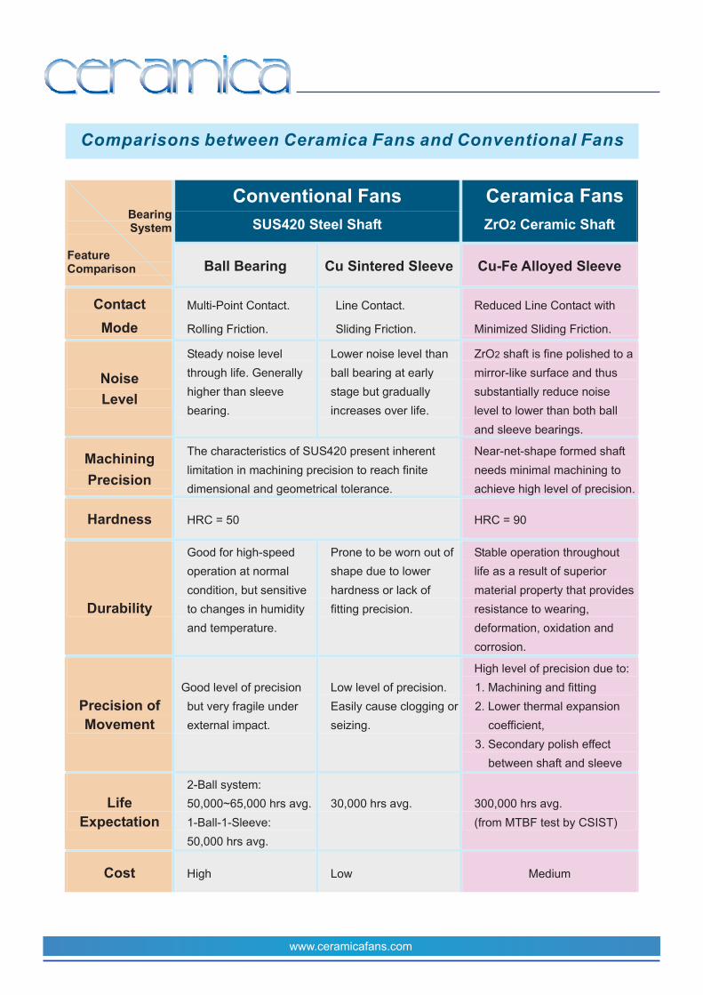
Comparisons between Ceramica Fans and Conventional Fans
Ceramica


![OVALE accessories - SANTI :: Vybavenie kúpeľní · OVALE accessories OVALE accessories [181] 25344 Porta scopino d'appoggio in ceramica bianca. White ceramic standing brush holder](https://img.pdfslide.us/doc/110x75/5be3b83709d3f281048c23e8/ovale-accessories-santi-vybavenie-kupelni-ovale-accessories-ovale-accessories.jpg)