Embed Size (px)
Citation preview
Ceramic Engineering
& Science Proceedings Volume 18, Number 2
A Collection of Papers Presented at the 98th Annual Meeting
and the Ceramic Manufacturing Council's
Workshop and Exposition
April 14-1 7, 1996 Indianaplois, Indiana
and September 22-1 5, 1996
Charlotte, North Carolina
Russell K. Wood Editor
Published by The American Ceramic Society 735 Ceramic Place
Westerville, OH 4308 1-61 36 Copyright 1997
ISSN 0 1 96-62 19
W. Paul Holbrook, Executive Director John 6. Wachtman, Society Publications Editor
Mark Mecklenborg, Director of Publications Mary J. Cassells, Product Manager, Books
Sarah Godby, Publishing Coordinator, Books Steven L. Hecker, Publications Production Manager
Rob Anania, Production Specialist
Committee on Publications: David J. Green, chair; Marina R. Pascucci; Man F. Yan; Richard Haber; James W. McCauley, ex officio; Prabhat Gupta, ex officio; Richard M. Spriggs, ex officio; Timothy M. Robinson, ex officio; John B. Wachtman Jr., ex officio; W. Paul Holbrook, ex officio.
Editorial and Subscription Offices: P.0 Box 61 36, Westerville, OH, 43086-61 36. Telephone (614) 794-5890; and Telefax (614) 899-61 09. Annual North American subscription rates are: member, $75; list, $95. Annual international subscription rates are member, $125; list, $145. Air mail is our standard delivery method to international customers. Libraries may call for package pricing. Single copies are $32 for members and $40 for nonmembers, plus postage and handling. Published five times a year. Printed in the United States of America. POSTMASTER: Please send address changes to Ceramic Engineering and Science Proceedings, P.0 Box 61 36, Westerville, OH, 43086-61 36. Periodical postage paid at Ann Arbor, MI, and additional mailing offices. Allow six weeks for address changes. CESPDK Vol. 18, No. 2, 1997
The American Ceramic Society assumes no responsibility for the statements and opinions advanced by the contributors to its publications or by the speakers at its programs.
Copyright 0 1997 by the American Ceramic Society. Permission to photocopy for personal or internal use beyond the limits of Sections 107 and 108 of the US. Copyright Law is granted by the American Ceramic Society, provided that the base fee of US$5.00 per copy, plus US$.50 per page, is paid directly to the Copyright Clearance Center, 222 Rosewood Dr., Danvers MA 01923, USA. The fee code for users of the Transactional Reporting Service for Ceramic Engineering and Science Proceedings is 01 96-621 9/97 $5.00+$.50. This consent does not extend to other kinds of copying, such as copying for general distribution, for advertising or promotional purposes, or for creating new collective works. Requests for special photocopying permission and reprint requests should be addressed to the Director of Publications, The American Ceramic Society, P.O. Box 61 36, Westerville, OH 43086-61 36.
Each issue of Ceramic Engineering and Science Proceedings, ISSN 01 96-621 9, includes a collection of technical articles in a general area of interest. These articles are of practical value for the ceramic industries and the general public. The issues are based on the proceedings of a conference. Both American Ceramic Society and non-Society conferences provide these technical articles. Each issue is organized by an editor who selects and edits material from the conference proceedings. The opinions expressed are entirely those of the presentors. There is no other review prior to publication.
Foreword
This issue of Ceramic Engineering and Science Proceedings contains many of the papers presented at the Annual Meeting of The American Ceramic Society in Indianapolis, Indiana, April 14-17, 1996, and the Ceramic Manufacturing Council’s Workshop and Exposition in Charlotte, North Carolina, September 22-25, 1996, under the co-sponsorship of The American Ceramic Society and the Ceramic Manufacturing Council.
The quality and variety of the papers is due almost entirely to the efforts of the authors in preparing them for publication, and the excellent format and printing are the result of the professionals at The American Ceramic Society who always man- age to produce consistently good publications.
My involvement, as usual, was to collect the papers, encourage people presenting papers to prepare them for publication (some people have called this “harass- ment”), and to make a quick review of each paper as received.
It is not possible to list everyone who helped with this issue, but in particular I would like to thank Lori Kozey and Sarah Godby, of the Society, for their efforts in turning a variety of papers in different formats and styles into a worthwhile publi- cation.
Russell K. Wood American Standard Inc.
... 111

Table of Contents
Foreword.. . . . . . . . . . . . . . . . . . . . . . . . . . . . . . . . . . . . . . . . . . . . . iii
Innovations in Decorating Badging Techniques . . . . . . . . . . . . . . . . . 1 Sally Alsop
Sintering and Modification of Porous Structure Caused by Binders Added to Whiteware Body Composition . . . . . . . . . . . . . 12
F. Andreola, P. Pozzi, and M. Romagnoli
Near-IR Photoluminescence of Manganese(V)-Doped Synthetic Materials and Related Minerals .................... 22
Maria Flora Barba, Pi0 Callejas, David Ajo, Giorgio Pozza, and Marco Bettinelli
Frit: The Engineered Material . . . . . . . . . . . . . . . . . . . . . . . . . . . . . .28 Todd Barson
Kiln Troubleshooting and the Fix. . . . . . . . . . . . . . . . . . . . . . . . . . . . 37 Lawrence E. Bauer
Chromite as a Pigment for Fast-Fired Porcelain Tiles. . . . . . . . . . . . 44 Federica Bondioli, Anna Maria Ferrari, Cristina Leonelli, and Tiziano Manfredini
Further Investigation of a Pressure Cast Sanitaryware Body with Emphasis on Permeability and Effect of Raw Material Selection. . . . . . . . . . . . . . . . . . . . . . . . . . . . . . . . . . . 59
A.K. Bougher and M.D. Etheridge
Application and Management of High-Velocity Burners on Tunnel Kilns Firing Structural Clay Brick . . . . . . . . . . . . . . . . . . . 69
Johnny M. Brown
Ceram. Eng. Sci. Proc., 18 [21 (1997) V
Lift Truck Safety . . . . . . . . . . . . . . . . . . . . . . . . . . . . . . . . . . . . . . . . 7 8 Gary Burkholder
The Metal Marking Behavior of Matte, Gloss, and Zircon-Opacified Glazes . . . . . . . . . . . . . . . . . . . . . . . . . . . . . . . . . . 8 1
R.J. Castilone and W.M. Carty
The Influence of ZrO, Particles on Ceramic Glazes
C. Concepcion, J.L. Oteo, E. Ocana, J. Rubio, and M.J. Velasco Used in the Single-Fired Tile Industry. . . . . . . . . . . . . . . . . . . . . . . . 96
Electric Utility Industry Restructuring: Duke Power’s Position . . . . 114
Novel Feedstocks for Powder Injection Molding. . . . . . . . . . . . . . . 127
The Relative Stability of Ceramic Pigments . . . . . . . . . . . . . . . . . . 139
Bob Edrnonds
R.A. Einhorn, N.J. Arnoroso, and L.E. Bogan
Douglas R. Eppler and Richard A. Eppler
Formulation of Leadless Glazes . . . . . . . . . . . . . . . . . . . . . . . . . . . 150 Richard A. Eppler and Douglas R. Eppler
Using a Consultant to Expand Your Technology Base. . . . . . . . . . .159 Richard A. Eppler and Douglas R. Eppler
Fort Cady in situ Borate Mining Project . . . . . . . . .
Electrophoretic Deposition of Compacts from
George J. Hartrnan
Clay Suspensions . . . . . . . . . . . . . . . . . . . . . . . . . .
A New Electronics-Grade Dispersant for the Improved Processibility of Technical Ceramics.
C.P. Howland, K.J. Moeggenborg, and G.J. Collias
1. Hector and R. Clasen
. . . . .
. . . . .
. . . . .
. . . .167
. . . .173
. . . .187
vi Ceram. Eng. Sci. Proc., 18 [21 (1997)
Constant Flow Rate Consolidation Behavior of Alumina Slurries. . . . . . . . . . . . . . . . . . . . . . . . . . . . . . . . . . . . . . .I99
B.J. Kellett and D.N. Ravishankar
A Procedure for Determining the Response of Organic Matter in Ball Clays to Alkaline Digestion . . . . . . . . . . . . . . . . . . . . 216
W.J. Kelly
Contact Damage Resistance of Whiteware Glazes . . . . . . . . . . . . . 228 William C. LaCourse and Mark T. Ucasz
The Role of Water in Glaze Defects. . . . . . . . . . . . . . . . . . . . . . . . . 23? William C. LaCourse and Walter Mason
Using Brookfield Analysis to Predict Slip Performance . . . . . . . . . 246 Bill Leach
Further Studies on the Effects of Different Ball Clays on Fast-Fire Floor and Wall Tile. . . . . . . . . . . . . . . . . . . . . . . . . . . .255-
Christopher A. Lombard0
Retrofitting Tunnel Kilns. . . . . . . . . . . . . . . . . . . . . . . . . . . . . . . . .262 J.J. Lukacs
High Heat Penetration: Theory and Practice . . . . . . . . . . . . . . . . . . 280 Fred McMann, Bruce Geisendorfer, and Todd Miller
Kaolin Delamination Techniques and Their Effects on Morphology, Crystallinity, and Suspension Rheology . . . . . . . . . . . 291
Chris 6. Maxwell and Prakash 6. Malla
Mining Safety the North Carolina Way . . . . . . . . . . . . . . . . . . . . . .304 Harold D. Megredy
Ceramic Glaze Materials: The Top Ten List . . . . . . . . . . . . . . . . . . . 308 Klaus Meinssen
Ceram. fng. Sci. Proc., 18 [21(1997) vii
Insulating with Ceramic Hollow Microspheres in Refractory Bricks and Castables . . . . . . . . . . . . . . . . . . . . . . . . . . .320
Stan Miller
The Impact of ABET on Cirriculum Content and Academic Standards. . . . . . . . . . . . . . . . . . . . . . . . . . . . . . . . . . . .333
Robert E. Moore
What Does It Take to Get a Promotion? . . . . . . . . . . . . . . . . . . . . .338 Robert T. Oxnard
Effects of Regulations on Materials Availability . . . . . . . . . . . . . . . 341 Michael 6. Quintin
Spray Drying and Implications for Compactibility of Product Granules . . . . . . . . . . . . . . . . . . . . . . . . . . . . . . . . . . . .343
James S. Reed
Significance of Wollastonite in Ceramic Whitewares . . . . . . . . . . . 359 Sara Robinson
Practical Applications of Pulse Firing in Tunnel Kilns for the Structural Clay Industry . . . . . . . . . . . . . . . . . . . . . . . . . . . 367
Jeffrey D. Ryan
A High-Sensitivity Thermal Method for Determining the Presence of Quartz at Levels Below 0.1 YO. . . . . . . . . . . . . . . . . . . .374
G.S. Sheffield and J.R. Schorr
Statistical Process Control Will Improve Your Quality and Profits . . . . . . . . . . . . . . . . . . . . . . . . . . . . . . . . . . . . .384
Milton A. Stumpff
Defect Analysis of Lithium Tetraborate Single Crystals by X-Ray Topography . . . . . . . . . . . . . . . . . . . . . . . . . . . .389
Tamotsu Sugawara, Ryuichi Komatsu, Satoshi Uda, and Koichi Sassa
viii Ceram. Eng. Sci. Proc., 18 [21 (1997)
Ensuring Safety Through Continuous Participation . . . . . . . . . . . . 397 Linnie Thomas
Refitting Existing Kilns to Improve Performance . . . . . . . . . . . . . . 398 Sam Tricase
Borate Raw Materials for the Ceramic Frit Industry . . . . . . . . . . . . 407 W. Vickery
The Future of The Storm Water Program . . . . . . . . . . . . . . . . . . . .418 Carmelita White
Acrylic Binders for Dry Pressing Ceramics. . . . . . . . . . . . . . . . . . .422 X. Kevin Wu, David W. Whitrnan, William L. Kaufell, William C. Finch. and Donald I. Cumbers
Water/Frit Interactions as a Source of Glazing Problems . . . . . . . . 439 C.H. Yoon, W.C. Lacourse, and W. Mason
Ceram. fng. Sci. Proc., 18 [21 (1997) ix

Inn ovations Techniques
Sally Alsop CERAM Research, Stoke-on-Trent, England
Two novel decoration techniques designed to improve the competitiveness of white- wares manufacturers are reviewed. The noncontact method of ink jet printing offers major advantages in terms of jlexibili9, cost reduction, and speed of application. A second method for the cold application of logos and decoration onto glost ware provides similar benefits, particularly for sanitaryware. The underlying principles and advantages of each technique are discussed and brief descriptions are given of the research, development, and application programs undertaken by CERAM Research.
Introduction Increased competition, especially from countries with low-cost labor, is a driving force for change within the ceramic industry in the United States and western Europe. In order to become more competitive, organizations are having to look at the areas of production where costs can be reduced, for example, labor, energy consumption per piece manufactured, work in progress, and quality control with a minimum of losses.
Additionally, production must respond rapidly to the market to ensure customer satisfaction. This requires manufacturing flexibility with produc- tion to order based on short processing times, automation of short runs, and automated quality control.
To achieve these goals requires parallel automated flow lines with short processing times that can be easily switched from one product to another and thereby able to respond rapidly to the dictates of the order book.
CERAM Research has identified a number of novel decorating tech- niques that will help achieve these goals, two of which are reviewed in this paper. The first is a noncontact (or ink jet) method of printing, and the sec- ond is a method for producing a nonfired decoration. The underlying prin- ciples and advantages and a brief outline of the work carried out at CERAM Research are discussed.
Ceram. Eng. Sci. Proc., 18 [21 (1997) 1
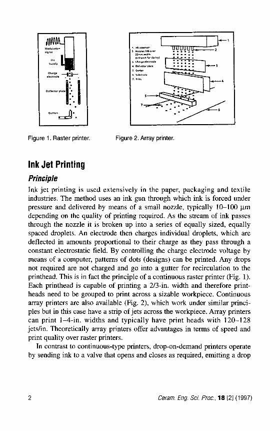
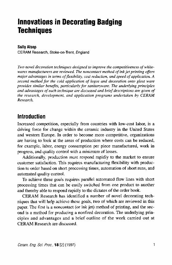
Figure 1. Raster printer. Figure 2. Array printer.
Ink Jet Printing Principle Ink jet printing is used extensively in the paper, packaging and textile industries. The method uses an ink gun through which ink is forced under pressure and delivered by means of a small nozzle, typically 10-100 pm depending on the quality of printing required. As the stream of ink passes through the nozzle it is broken up into a series of equally sized, equally spaced droplets. An electrode then charges individual droplets, which are deflected in amounts proportional to their charge as they pass through a constant electrostatic field. By controlling the charge electrode voltage by means of a computer, patterns of dots (designs) can be printed. Any drops not required are not charged and go into a gutter for recirculation to the printhead. This is in fact the principle of a continuous raster printer (Fig. 1). Each printhead is capable of printing a 2/3-in. width and therefore print- heads need to be grouped to print across a sizable workpiece. Continuous array printers are also available (Fig. 2), which work under similar princi- ples but in this case have a strip of jets across the workpiece. Array printers can print 1-4-in. widths and typically have print heads with 120-128 jetdin. Theoretically array printers offer advantages in terms of speed and print quality over raster printers.
In contrast to continuous-type printers, drop-on-demand printers operate by sending ink to a valve that opens and closes as required, emitting a drop
2 Ceram. Eng. Sci. Proc., 18 [21 (1997)
of ink through a nozzle. This technology is considerably slower than con- tinuous printing and the printhead needs to be very close to the substrate.
Advantages The fact that the printhead does not touch the work piece means that the design can be applied to any surface texture and to delicate surfaces such as unfired glazes and clay ware.
Ink jet printers are capable of high speeds. This depends on the number of jets used and the quality of printing required. For ceramic printing it is estimated that speeds of between 1 and 10 ft/s should be achievable.
Ink jet printing is versatile. The designs are computer generated and con- trolled and thus can be easily manipulated, for example, enlarged, reduced, or made for a particular shape.
There is no waste, because any ink not used is recirculated to the print- head. This is a particular advantage if expensive decoration media, such as gold or platinum, are being used.
This form of decorating technique has the potential to be multicolor. Theoretically there is no limit to the number of arrays and hence the num- ber of colors that can be used, but practically the number of colors will be limited by the power of the computer used to control the drops and com- mercially by the cost of the overall system.
Ink Research and Development The main thrust of the work at CERAM Research has been concerned with developing ceramic inks that are compatible with commercially available machines The ink must have a low viscosity (2-8 MPa-s) to ensure that the ink passes easily through filters, which protect the printing head from dirt, as well as the nozzles. They must also be conductive (30-160 mScm-l) in order to be charged and deflected. Surface tension (0 03-0.06 Nm-') must also be controlled as this determines the break up of the stream into droplets; careful control is necessary for precise printing. The pH should be slightly alkaline so as not to be corrosive to the nozzle. Additionally the inks must be compatible with the substrate, have a shelf life that is com- mercially acceptable, and satisfy their decorative role.
Three ink systems are felt to offer potential: 1. Pigmented inks: These are conventionally prepared ceramic pig-
ments dispersed in an aqueous medium. The ink must contain less
Ceram. Eng. Sci. Proc., 18 121 (1 997) 3
than 50 wt% solids that possess a particle size distribution of 100% c2 pm. Improving the shelf life of these inks is a technical chal- lenge yet to be overcome. Within as little as 24 h, the suspensions agglomerate and block the filters and nozzles. The most stable col- ors are based on zircon. Zeta potential measurements should pro- vide more information on stabilityhtability mechanisms.
2. Soluble inks: These are generally transition metal salts that have been rendered more soluble by an organic complexing agent. Complexing in this way allows for greater ink stability, more intense colors, and the pH to be raised and buffered to an accept- able level. Blue, olive, brown, and grayblack inks have been devel- oped that run through current commercial printers. The color is dependent upon temperature substrate and kiln atmosphere. Also included in this category are the liquid golds and other precious metals since these are organometallic resins that do not include any pigment. A water-based platinum ink was successfully ink jet print- ed around flatware using an adapted banding machine.
3. High-surface-area pigments: These are thermally stable ceramic pigments having the conventional pigment crystal structure but with a high surface area. A solution of mixed metal salts is pre- pared and ink jet printed with the pigment particles formed in situ on the substrate. In this way the problems of agglomeration and nozzle blockage typically encountered with traditional pigmented inks are avoided. The work is loosely based on the nitrate-glycinel and Pechini2 methods of producing oxide powders. The nitrate- glycine route uses glycine as a complexing agent, whereas in the Pechini method the desired metal cations are solubilized in water using citric acid as the chealating agent.
Control of Print Quality Quality of print decoration is of paramount importance and for ink jet print- ing this is mainly dependent upon the achievable dot size. This is affected by:
The substrate, which can cause different spreading of the ink. Ink movement on the substrate, particularly during firing. Nozzle diameter. The smaller the nozzle diameter, the better the print quality; however, even the use of even the smallest nozzles currently available (35 pm) has failed so far to produce good quality prints.
4 Cerarn. Eng. Sci. Proc., 18 [21 (1 997)
Computer software. At present computers are not powerful or sophisticated enough to accurately direct drops or combina- tions of drops to the cor- rect place in a single pass at high speed to produce high-quality prints. Hardware. Two limitations exist: nozzle-ink compati- bility and the size of area
the stitch line being seen. The latter arises when two or more printheads, out of necessity, are used.
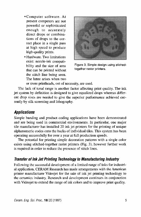
Figure 3. Simple design using stiched-
that can be printed without together raster Printers.
The lack of tonal range is another factor affecting print quality. The ink jet system by definition is designed to give equalized drops whereas differ- ent drop sizes are needed to give the superior performance achieved cur- rently by silk screening and lithography.
Applications Simple banding and product coding applications have been demonstrated and are being used in commercial environments. In particular, one major tile manufacturer has installed 20 ink jet printers for the printing of unique alphanumeric codes onto the backs of individual tiles. This system has been operating successfully for over a year at full production speeds.
The potential for printing simple decoration patterns with a single color exists using stitched-together raster printers (Fig. 3), however further work is required in order to reduce the presence of stitch lines.
Transfer of Ink Jet Printing Technology to Manufacturing Industry Following the successful development of a limited range of inks for industri- al application, CERAM Research has made arrangements with the American printer manufacturer Videojet for the sale of ink jet printing technology to the ceramics industry. Research and development continues in conjunction with Videojet to extend the range of ink colors and to improve print quality.
Ceram. Eng. Sci. Proc., 18 [21 (1997) 5
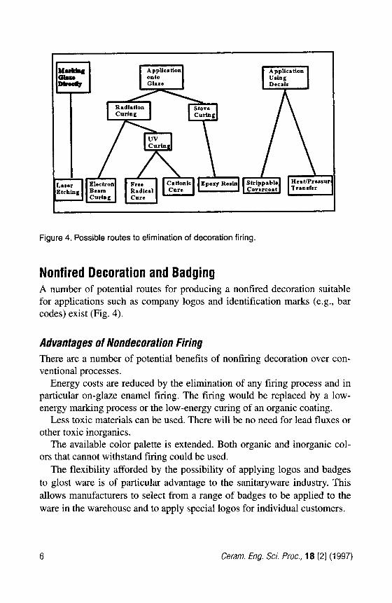
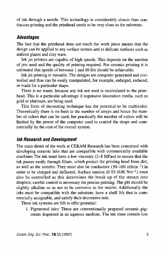
Figure 4. Possible routes to elimination of decoration firing.
Nonfired Decoration and Badging A number of potential routes for producing a nonfired decoration suitable for applications such as company logos and identification marks (e.g., bar codes) exist (Fig. 4).
Advantages of Nondecoration Firing There are a number of potential benefits of nonfiring decoration over con- ventional processes.
Energy costs are reduced by the elimination of any firing process and in particular on-glaze enamel firing. The firing would be replaced by a low- energy marking process or the low-energy curing of an organic coating.
Less toxic materials can be used. There will be no need for lead fluxes or other toxic inorganics.
The available color palette is extended. Both organic and inorganic col- ors that cannot withstand firing could be used.
The flexibility afforded by the possibility of applying logos and badges to glost ware is of particular advantage to the sanitaryware industry. This allows manufacturers to select from a range of badges to be applied to the ware in the warehouse and to apply special logos for individual customers.
6 Cerarn. Eng. Sci. Pfuc., 18 [21 (1 997)
Assessment of Decoration Routes Direct marking of glaze surfaces could be done by laser etching. This would be sufficient for coding purposes and would be very permanent. For decorative applications the etched mark would need to be filled with an ink that could be wiped off the surrounding glaze surface prior to dryingkur- ing. Scanning lasers are fairly expensive and for designs of any complexity or incorporating large solid areas the marking process is slow. Lasers also cannot produce the required quality for most applications.
An alternative to etching the glaze is to apply a permanent nonfired mark. This can be produced using either radiation or stove curing materials.
The attraction of radiation curable coatings is that after printing a design or coating on a surface, they can be cured virtually instantaneously when exposed to radiation. The radiation used is either electron beam (EB) or ultraviolet (UV). Radiation curing, and in particular UV curing, is consid- ered to have the most potential for use as decoration.
Stove curing products are basically two pack systems consisting of an epoxy resin and a hardener (to catalyze the cure) that are mixed together at the point of use. Epoxy staving media are already used commercially for some tableware backstamping applications but the lengthy curing times required (2-4 min) for room temperature (cold) setting make them less attractive than radiation-cured materials.
Nonfired decorative effects could also be achieved using decals. For application of cold setting inks from a transfer paper, the main problem is the transparent carrier film, which remains visible and could become conta- minated and scratched in service. This could be avoided by physically removing the carrier film after application or by direct transfer from the paper. While some systems exist that might be adapted, for example, strip- pable covercoat and thermal and pressure release methods, considerable development is still required for ceramic application.
Principle of Radiation Curing Radiation curable coatings can be cured virtually instantaneously when exposed to radiation. The radiation used is either electron beam or ultravio- let with the former being more energy-intensive, thus giving more cross linked films. UV radiation can be used to initiate curing using two alterna- tive cure systems: free-radical cure and cationic cure.
Ceram. Eng. Sci. Proc., 18 [21 (1997) 7
Electron Beam vs. Ultra Violet Curing In EB curing the radiation consists of a beam of electrons drawn from a hot wire filament cathode. The electrons are then accelerated under vacuum across a potential difference to attain very high speeds and directed onto the material to be cured through a metal foil window. An article is coated with an EB-cur- able material, usually comprising acrylic prepolymers and monomers, then passed through the electron beam. The high-energy electrons interact with the organic coating to produce reactive free radicals that react with double bonds in the acrylate groups to bring about polymerization.
This contrasts with UV curing, where it is necessary to incorporate an extra component called a photo-initiator, which gives free radicals when irra- diated with UV.
EB is more expensive than UV curing in terms of capital equipment; this rules it out for most applications. However, EB-cured coatings can have supe- rior durability and color stability compared with similar W-cured coatings.
EB curing generates very little heat in the substrate being coated and con- sequently, where the substrate is paper, there should be very little moisture loss and consequent distortion, which can be a problem with UV curing.
Comparison of UV Cure Systems The radiation from UV lamps needs a photo-initiator to be incorporated into the coating formulation. The two curing systems in use, free-radical and cationic, require different types of photo-initiators. However, the same type of UV curing equipment can be used to provide the radiation in both cases.
The curing equipment consists of a light source, a reflector, and appro- priate arrangements for cooling and shielding. Almost all the lamps used for curing coatings are medium-pressure mercury vapor lamps since these give a spectral output that ranges from 200 nm into the visible wavelengths and, in particular, have emission lines at about 365 nm, which are effective in activating many photo-initiators.
Originally all lamps incorporated electrodes that when warmed up vapor- ized mercury in the tube, producing a characteristic emission spectrum. The disadvantages are that they require 15-30 min to strike up and the output of the lamps falls off progressively throughout their life.
Electrodeless lamps are available that are more costly but have quicker start up (within seconds) and restart. They have a longer life and a more consistent output.
8 Cerarn. Eng. Sci. Proc., 18 [21 (1997)
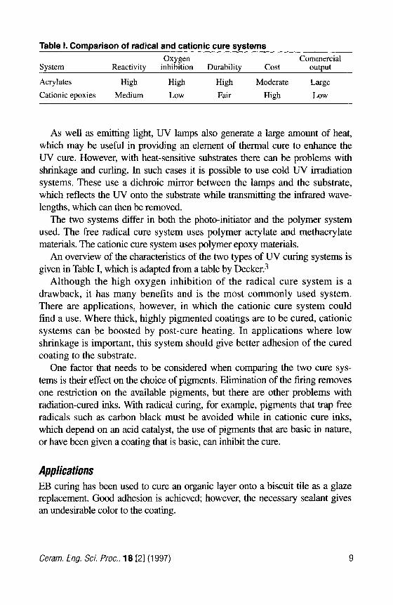
Table 1. Comparison of radical and cationic cure systems Oxygen Commercial
System Reactivity inhibition Durability Cost output
Cationic epoxies Medium Low Fair High Low
Acrylates High High High Moderate Large
As well as emitting light, UV lamps also generate a large amount of heat, which may be useful in providing an element of thermal cure to enhance the UV cure. However, with heat-sensitive substrates there can be problems with shrinkage and curling. In such cases it is possible to use cold UV irradiation systems. These use a dichroic mirror between the lamps and the substrate, which reflects the UV onto the substrate while transmitting the infrared wave- lengths, which can then be removed.
The two systems differ in both the photo-initiator and the polymer system used. The free radical cure system uses polymer acrylate and methacrylate materials. The cationic cure system uses polymer epoxy materials.
An overview of the characteristics of the two types of UV curing systems is given in Table I, which is adapted from a table by D e ~ k e r . ~
Although the high oxygen inhibition of the radical cure system is a drawback, it has many benefits and is the most commonly used system. There are applications, however, in which the cationic cure system could find a use. Where thick, highly pigmented coatings are to be cured, cationic systems can be boosted by post-cure heating. In applications where low shrinkage is important, this system should give better adhesion of the cured coating to the substrate.
One factor that needs to be considered when comparing the two cure sys- tems is their effect on the choice of pigments. Elimination of the firing removes one restriction on the available pigments, but there are other problems with radiation-cured inks. With radical curing, for example, pigments that trap free radicals such as carbon black must be avoided while in cationic cure inks, which depend on an acid catalyst, the use of pigments that are basic in nature, or have been given a coating that is basic, can inhibit the cure.
Applications EB curing has been used to cure an organic layer onto a biscuit tile as a glaze replacement. Good adhesion is achieved; however, the necessary sealant gives an undesirable color to the coating.
Ceram. Eng. Sci. Proc., 18 [21 (1997) 9
EB curing has also been used to cure a colored design onto a glazed sur- face with the pigment dispersed in a clear varnish. However, adhesion to the glaze is poor and further work is required.
UV curing has been used to cure a UV varnish layer on a tile but a strong yellow coloration and poor gloss resulted.
UV curing has also been used to cure UV adhesives applied by screen printing with a coloring agent. These showed very promising adhesion to the glaze and detergent resistance but careful control of the curing condi- tions was required to produce full hardness. A range of pigment dispersions can be added to the adhesive to give white, black, red, yellow, pale green, and blue colors while retaining the ability to be UV cured. These pigments are specially selected to minimize interference with the curing process and it is not possible to add pigments randomly.
In summary, therefore, pigmented acrylic UV curable adhesives appear to offer the best option for applying a permanent nonfired decoration or mark because they allow almost instant curing. Cationic UV curable resins can produce very hard coatings because cure can continue after exposure and they have low shrinkage.
Future Development of Nonfired Badging Trials to date have resulted in an acrylic-based, UV-cured system with very good adhesion when applied to glost ware and with very good clarity and definition. This system is particularly well suited to the application of badges and logos to sanitaryware.
Arrangements have been made for further development with a commer- cial supplier of UV-curable adhesives, curing lamps, and all that is required for an operational system. Future development work will concentrate on: definition of the required standards for abrasion resistance and chemical resistance, and ensuring that the adhesive meets these standards.
Acknowledgments The author wishes to acknowledge with thanks the work of her colleagues, in particular Mark Hobbs and John Birtles, at CERAM Research.
10 Ceram. Eng. Sci. Proc., 18 [21 (1997)
References 1 L.A. Chick et al., “Glycine-Nitrate Combustion Synthesis of Oxide Ceramic Powders,”
2 M.P. Pechini, U.S. Patent No. 3 330 697, July 11, 1967. 3 C. Decker, “UV Curing Chemistry: Past, Present, and Future,” J. Coatings Tech., 59
Matel: Lett., 10 [l-21 6 (1990).
[251] 97 (1987).
Ceram. Eng. Sci. Proc., 18 [21 (1997) 11
Sintering and Modification of Porous Structure Caused by Binders Added to Whiteware Body Composition
F. Andreola, P. Pozzi, and M. Romagnoli University of Modena, Modena, Italy
Introduction Cold isostatic pressing is a production process used to form ceramic com- ponents. It is applied especially to refractories, advanced ceramics, and tableware. In some fields, for example, tableware, it took its place relatively quickly, displacing conventional methods such as throwing or casting. This development is justified by the economic and technological advantages it brings. It will also be furthered by the continuously increasing demands on the quality of ceramic products.’ Its versatility enables it to be used for the manufacture of almost all flatware and other complicated articles, irrespec- tive of the article’s symmetry.2 The general advantages of isostatic pressing are very few size or dimensional limitations, very uniform pressed com- pacts, generally moderate tooling costs, and short overall process times3 Bartusch and Schulle noted that “a specific phenomenon of isostatic press- ing is the elastic re-expansion of pressed ware after shaping (spring- back).”’ This is caused by the release of both elastic energy stored in clay raw materials and the compressed air in the pores during the compression p h a ~ e . ~ ? ~ The immediately effective expansion after removal from the mold is particularly dangerous because it determines fractures and thus a weak- ening of body. Binders are added to the slurry to control the elastic recov- ery and to prevent damage to pressed bodies. During firing, elimination of the binder occurs and this process could introduce defects. The loss of binder can cause the formation of porosity in the body in two different ways. First, the binder can recede in the interparticle porosity, creating a porous shell that increases in size as pyrolysis proceeds. Second, capillary pressure in the porous body causes rearrangement of the binder, creating a distribution of porosity in the a r t i f a ~ t . ~ ? ~ Several parameters influence the process: rate of heating, geometry of the body, atmosphere in which burn- out is carried out, formation of porosity, characteristics of raw materials,
12 Ceram. Eng. Sci. Roc., 18 121 (1997)
and binder. Here the result obtained by studying the behavior of two viscos- ity-grade polyvinyl alcohols at two different percentages are reported. These binders were added to the slurry that was used for the preparation of tableware by isostatic pressing as regards the development of porous net- work during the firing. In particular, the influence of the characteristics of the binder on the formation and evolution of the pores during burn-out and their impact on the result of the sintering are considered. The work repre- sents the second part of a wider program. It aims at more in-depth investi- gation of the behavior of corporated binders, for example, polyvinyl alco- hols, added in whiteware body compositions for tableware.*
Expe ri m e n ta I A low- (800 monomer number) and a high- (2000 monomer number) vis- cosity-grade polyvinyl alcohol (Waker) with a linear chain were added to an industrial-base slurry with a typical formulation for white tableware. The binders were added as liquid solution in quantities corresponding to 0.5 and 1.5 wt% (solid/solid) with plasticizer (0.05 wt% Zusoplast 9002 by Ceramco) and deflocculant (0.2-0.6 wt% sodium metasilicate in solution). In all the cases, a strong agitation by means of a stirrer and the further addi- tion of water and deflocculant were necessary to obtain a good workability. In fact, the binder caused a considerable flocculation in the systems and an increase of viscosity. The slurries were spray-dried in semi-industrial counter-current spray dryers (SACMI) to attain similar granule size distribu- tion. Plates with a diameter of about 30 cm and weight of about 610 g, vari- able with respect to the binder added, were obtained by isostatic pressing. Measurements of TGA (Thermobalance STA409, Netzch) and dilatometry (Netzch) were carried out on the prepared samples. By these measurements, some characteristic temperatures for the sintering process (200, 350, 450, 700, 1200, and 1240°C) were defined. Pieces of plates were fired in a labo- ratory furnace at the temperatures indicated above. The crystalline structure of the fired samples was determined by X-ray (Phillips PW3710). Bulk den- sity and porosity were determined by mercury porosimeter (Micromeritics Autopore 9215 11). Measurements on the plates were performed on single- peaches of about 0.5 g. Pressure range was from 3.45 kPa to 414 MPa, cor- responding to pores with diameters from 360 to 0.003 ym. The equilibration times, for both intrusion and extrusion runs, were 10 s. After the measure- ments, the samples did not present fracture or deformation, as could be seen
Ceram. Eng. Sci. Proc., 18 [21 (1997) 13
by microscope. The content of binders in the sample at the different temper- atures was determined by measuring the carbon content by an elemental analyzer (Car10 Erba model 1106). Analysis by SEM (Philips XL 40) was also done.
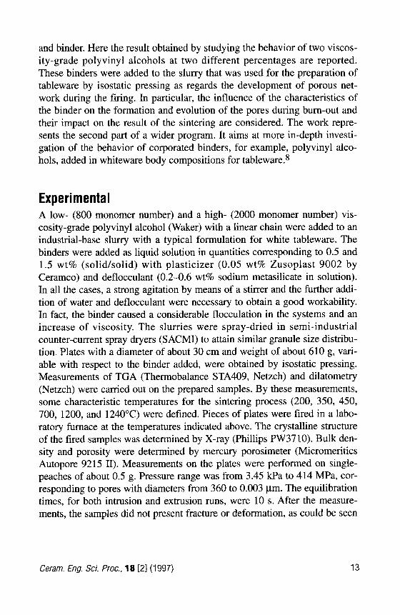
Results and Discussion TGA and Dilafometry The results obtained by TGA are shown in Fig. 1. In the curve, three weight losses are represented. The first (about 25-100°C) is due to the water pre- sent as moisture. The second (about 240-340°C) is the partial burn-out of binder. The third (about 450-700°C) is caused by clay dehydroxylation, combustion of organic materials contained in the raw materials, and the completion of binder bum-out. On the basis of this behavior, six tempera- tures were selected as useful to study the modification of the porous net- work. The temperatures 200 and 350°C were chosen to determine the mate- rial structure before and after the first partial burn-out, 450 and 700°C to determine the modification of the material during the process of deoxy- drillation, and 1200 and 1240°C to evaluate the results of the sintering
0
-1
-2
; -3 0 .- 5 . 4
-5
-6
-7
Tmpuature ('C)
Figure 1. T,, curve for the binder at high molecular weight at 20'C/min.
14 Ceram. Eng. Sci. Proc., 18 [21 (1997)
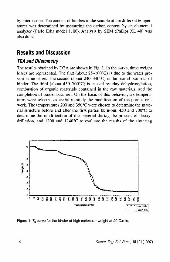
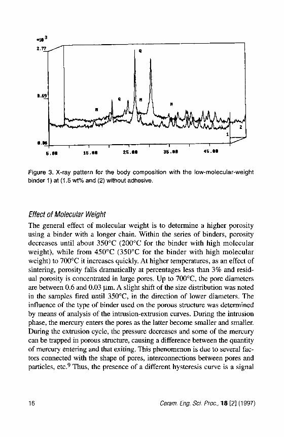
process. Dilatometries do not present substantial differences among the samples containing the different binders. Figure 2 shows the curves for the samples with high molecular weight binder and without adhesive. In curve 1 it is possible to observe a slight variation of inclination around 300°C, due to the partial elimination of the binder.
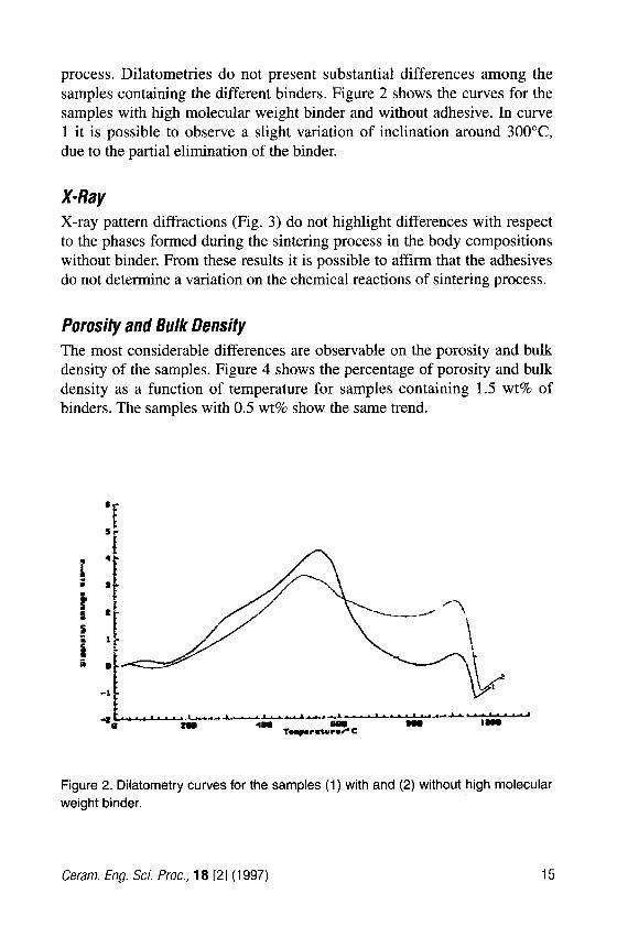
X-Ray X-ray pattern diffractions (Fig. 3) do not highlight differences with respect to the phases formed during the sintering process in the body compositions without binder. From these results it is possible to affirm that the adhesives do not determine a variation on the chemical reactions of sintering process.
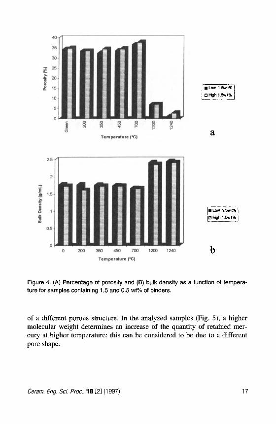
Porosity and Bulk Density The most considerable differences are observable on the porosity and bulk density of the samples. Figure 4 shows the percentage of porosity and bulk density as a function of temperature for samples containing 1.5 wt% of binders. The samples with 0.5 wt% show the same trend.
Figure 2. Dilatometry curves for the samples (1) with and (2) without high molecular weight binder.
Ceram. Eng. Sci. froc., 18 121 (1997) 15
I
0.111 I 1 1 I I I 1 I I
15.00 25 .a0 35.00 45.00 6.011
Figure 3. X-ray pattern for the body composition with the low-molecular-weight binder 1) at (1.5 wt% and (2) without adhesive.
Effect of Molecular Weight The general effect of molecular weight is to determine a higher porosity using a binder with a longer chain. Within the series of binders, porosity decreases until about 350°C (200°C for the binder with high molecular weight), while from 450°C (350°C for the binder with high molecular weight) to 700°C it increases quickly. At higher temperatures, as an effect of sintering, porosity falls dramatically at percentages less than 3% and resid- ual porosity is concentrated in large pores. Up to 700°C, the pore diameters are between 0.6 and 0.03 pm. A slight shift of the size distribution was noted in the samples fired until 350"C, in the direction of lower diameters. The influence of the type of binder used on the porous structure was determined by means of analysis of the intrusion-extrusion curves. During the intrusion phase, the mercury enters the pores as the latter become smaller and smaller. During the extrusion cycle, the pressure decreases and some of the mercury can be trapped in porous structure, causing a difference between the quantity of mercury entering and that exiting. This phenomenon is due to several fac- tors connected with the shape of pores, interconnections between pores and particles, e t ~ . ~ Thus, the presence of a different hysteresis curve is a signal
16 Ceram. Eng. Sci. Proc., 18 [21 (1997)
40
Temperature (T)
0 200 350 450 700 1200 1240
Temptrature (T)
a
b
Figure 4. (A) Percentage of porosity and (B) bulk density as a function of tempera- ture for samples containing 1.5 and 0.5 wt% of binders.
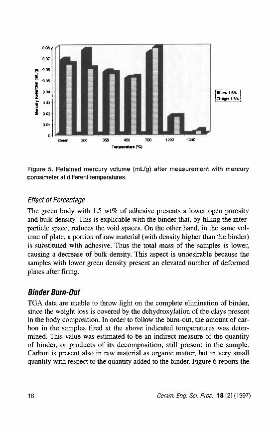
of a different porous structure. In the analyzed samples (Fig. 5) , a higher molecular weight determines an increase of the quantity of retained mer- cury at higher temperature; this can be considered to be due to a different pore shape.
Cerarn. Eng. Sci. Proc., 18 121 (1997) 17
0.07 1 5 2 o'M: 0.05
1 0.04- I $ 0.03-
f 4 0.02-
Figure 5. Retained mercury volume (mL/g) after measurement with mercury porosimeter at different temperatures.
Effect of Percentage The green body with 1.5 wt% of adhesive presents a lower open porosity and bulk density. This is explicable with the binder that, by filling the inter- particle space, reduces the void spaces. On the other hand, in the same vol- ume of plate, a portion of raw material (with density higher than the binder) is substituted with adhesive. Thus the total mass of the samples is lower, causing a decrease of bulk density. This aspect is undesirable because the samples with lower green density present an elevated number of deformed plates after firing.
Binder Burn-Out TGA data are unable to throw light on the complete elimination of binder, since the weight loss is covered by the dehydroxylation of the clays present in the body composition. In order to follow the burn-out, the amount of car- bon in the samples fired at the above indicated temperatures was deter- mined. This value was estimated to be an indirect measure of the quantity of binder, or products of its decomposition, still present in the sample. Carbon is present also in raw material as organic matter, but in very small quantity with respect to the quantity added to the binder. Figure 6 reports the
18 Ceram. Eng. Sci. Proc., 18 [21 (1997)