Embed Size (px)
Citation preview
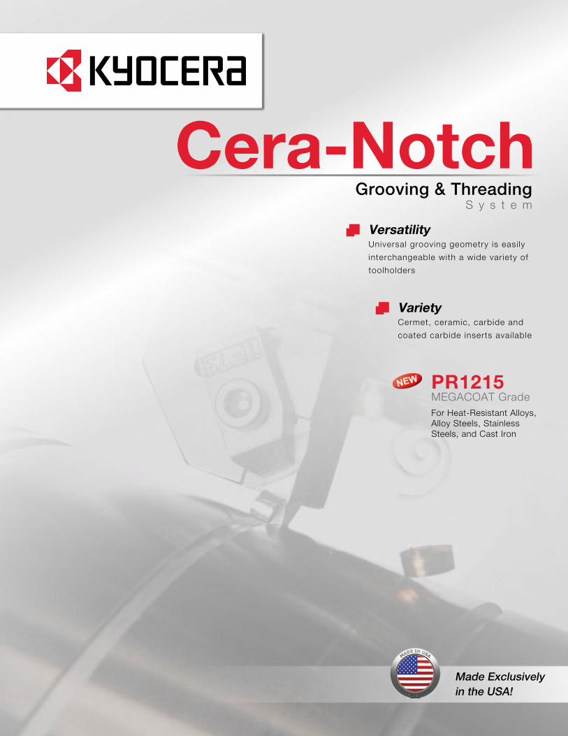
PR1215MEGACOAT GradeFor Heat-Resistant Alloys,Alloy Steels, Stainless Steels, and Cast Iron
Cera-Notch
VarietyCermet, ceramic, carbide and
coated carbide inserts avai lable
VersatilityUniversal grooving geometry is easi ly
interchangeable with a wide variety of
toolholders
Made Exclusivelyin the USA!
Grooving & ThreadingS y s t e m
2
Cera-Notch System
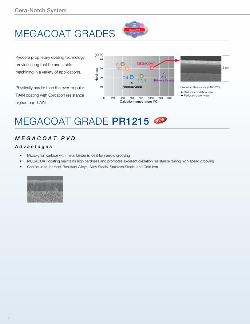
A d v a n t a g e s
M E G A C O A T P V D
• Micro-grain carbide with metal binder is ideal for narrow grooving
• MEGACOAT coating maintains high hardness and promotes excellent oxidation resistance during high speed grooving
• Can be used for Heat-Resistant Alloys, Alloy Steels, Stainless Steels, and Cast Iron
Oxidation Resistance (�1000�C)
� Reduces oxidation wear� Reduces crater wear
MEGACOAT GRADE PR1215
MEGACOAT GRADES
Oxidation temperature (°C)
10
20
30
40
0 200 400 600 800 1000 1200 1400
TiCNTiC MEGACOAT
TiAINTiN
(Reference: Carbide)
(Reference: Ceramic)Al2O3
(GPa)
Har
dnes
s
Kyocera proprietary coating technology
provides long tool life and stable
machining in a variety of applications.
Physically harder than the ever-popular
TiAlN coating with Oxidation resistance
higher than TiAlN
2�m
3
Cera-Notch System
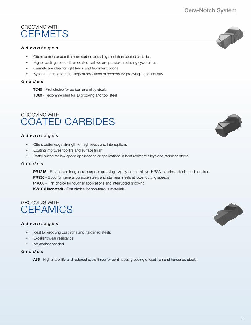
GROOVING WITH
A d v a n t a g e s
G r a d e s
• Offers better edge strength for high feeds and interruptions
• Coating improves tool life and surface finish
• Better suited for low speed applications or applications in heat resistant alloys and stainless steels
PR1215 - First choice for general purpose grooving. Apply in steel alloys, HRSA, stainless steels, and cast iron
PR930 - Good for general purpose steels and stainless steels at lower cutting speeds
PR660 - First choice for tougher applications and interrupted grooving
KW10 (Uncoated) - First choice for non-ferrous materials
COATED CARBIDES
GROOVING WITH
A d v a n t a g e s
G r a d e s
• Offers better surface finish on carbon and alloy steel than coated carbides
• Higher cutting speeds than coated carbide are possible, reducing cycle times
• Cermets are ideal for light feeds and few interruptions
• Kyocera offers one of the largest selections of cermets for grooving in the industry
TC40 - First choice for carbon and alloy steels
TC60 - Recommended for ID grooving and tool steel
CERMETS
GROOVING WITH
A d v a n t a g e s
G r a d e s
• Ideal for grooving cast irons and hardened steels
• Excellent wear resistance
• No coolant needed
A65 - Higher tool life and reduced cycle times for continuous grooving of cast iron and hardened steels
CERAMICS
4
Case Studies
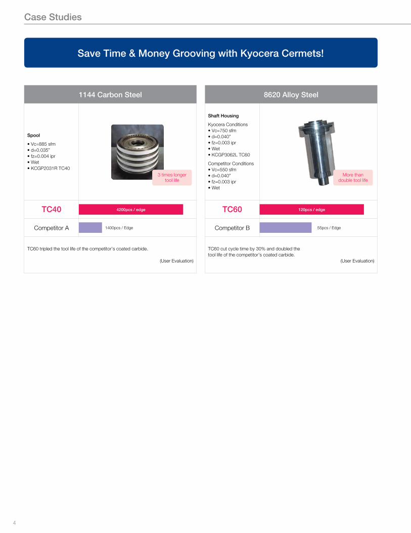
Save Time & Money Grooving with Kyocera Cermets!
1144 Carbon Steel
Spool
• Vc=885 sfm• d=0.035”• fz=0.004 ipr• Wet• KCGP2031R TC40
TC40 4200pcs / edge
Competitor A 1400pcs / Edge
TC60 tripled the tool life of the competitor’s coated carbide.
(User Evaluation)
3 times longer tool life
8620 Alloy Steel
Shaft Housing
Kyocera Conditions• Vc=750 sfm• d=0.040”• fz=0.003 ipr• Wet• KCGP3062L TC60
Competitor Conditions• Vc=550 sfm• d=0.040”• fz=0.003 ipr• Wet
TC60 120pcs / edge
Competitor B 55pcs / Edge
TC60 cut cycle time by 30% and doubled thetool life of the competitor’s coated carbide.
(User Evaluation)
More than double tool life
5
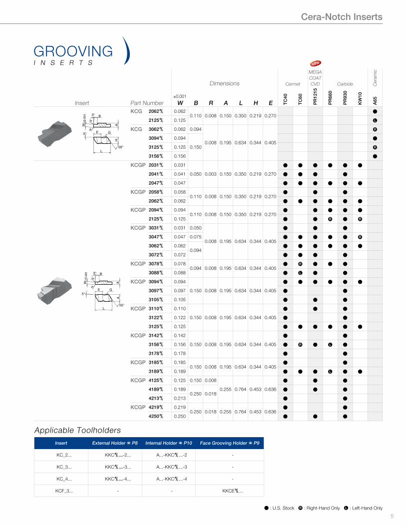
Cera-Notch Inserts
Insert Part Number
Dimensions Cermet
MEGACOATCVD Carbide C
eram
ic
±0.001
W B R A L H E TC40
TC60
PR
1215
PR
660
PR
930
KW
10
A65
E G
L55°
Hrε±0
.001
W
rε
3° BA
0°
KCG 2062§ 0.0620.110 0.008 0.150 0.350 0.219 0.270
Þ
2125§ 0.125 Ä
KCG 3062§ 0.062 0.094
0.008 0.195 0.634 0.344 0.405
Å
3094§ 0.094
0.150
Þ
3125§ 0.125 Å
3156§ 0.156 Þ
E G
L
A
±0.0
01W
rε
rε
A
3° B
55°
5°
KCGP 2031§ 0.031
0.050 0.003 0.150 0.350 0.219 0.270
Þ Þ Þ Þ Þ Þ
2041§ 0.041 Þ Þ Þ Þ
2047§ 0.047 Þ Þ Þ Þ Þ Þ
KCGP 2058§ 0.0580.110 0.008 0.150 0.350 0.219 0.270
Þ Þ Þ
2062§ 0.062 Þ Þ Þ Þ Þ Þ
KCGP 2094§ 0.0940.110 0.008 0.150 0.350 0.219 0.270
Þ Þ Þ Þ Þ
2125§ 0.125 Þ Þ Å Þ Å
KCGP 3031§ 0.031 0.050
0.008 0.195 0.634 0.344 0.405
Þ Þ Þ
3047§ 0.047 0.075 Þ Þ Þ Þ Þ Å
3062§ 0.0620.094
Þ Þ Þ Þ Þ Þ
3072§ 0.072 Þ Þ Þ Þ
KCGP 3078§ 0.0780.094 0.008 0.195 0.634 0.344 0.405
Þ Å Þ Þ Þ
3088§ 0.088 Þ Ä Þ Þ
KCGP 3094§ 0.094
0.150 0.008 0.195 0.634 0.344 0.405
Þ Þ Þ Þ Þ Þ
3097§ 0.097 Þ Þ
3105§ 0.105 Þ Þ Þ
KCGP 3110§ 0.110
0.150 0.008 0.195 0.634 0.344 0.405
Þ Þ Þ
3122§ 0.122 Þ Þ
3125§ 0.125 Þ Þ Þ Þ Þ Þ
KCGP 3142§ 0.142
0.150 0.008 0.195 0.634 0.344 0.405
Þ Þ
3156§ 0.156 Þ Å Þ Ä Þ
3178§ 0.178 Þ Þ
KCGP 3185§ 0.1850.150 0.008 0.195 0.634 0.344 0.405
Þ Þ
3189§ 0.189 Þ Þ Þ Ä Þ Þ
KCGP 4125§ 0.125 0.150 0.008
0.255 0.764 0.453 0.636
Þ Þ Þ
4189§ 0.1890.250 0.018
Þ Þ Þ
4213§ 0.213 Þ Þ
KCGP 4219§ 0.2190.250 0.018 0.255 0.764 0.453 0.636
Þ Þ
4250§ 0.250 Þ Þ Þ
GROOVINGI N S E R T S
Þ : U.S. Stock Å : Right-Hand Only Ä : Left-Hand Only
Insert External Holder � P8 Internal Holder � P10 Face Grooving Holder � P9
KC_2... KKC§...-2... A...-KKC§...-2 -
KC_3... KKC§...-3... A...-KKC§...-3 -
KC_4... KKC§...-4... A...-KKC§...-4 -
KCF_3... - - KKCE§...
Applicable Toolholders
6
Þ : U.S. Stock Å : Right-Hand Only Ä : Left-Hand Only
Insert Part Number
Dimensions Cermet
MEGACOATCVD Carbide C
eram
ic±0.001
W B R A L H E TC40
TC60
PR
1215
PR
660
PR
930
KW
10
A65
E G
55°L
rε
5°
±0.0
01W
HA
3° B
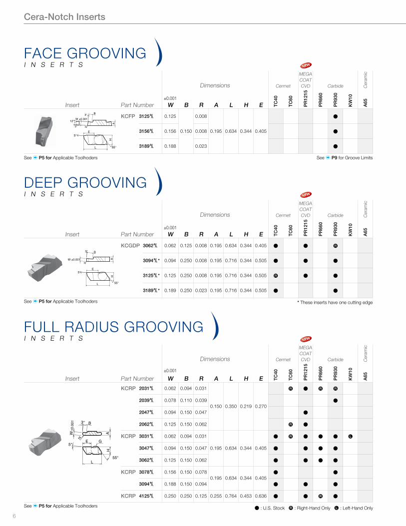
KCRP 2031§ 0.062 0.094 0.031
0.150 0.350 0.219 0.270
Å Þ Å Å
2039§ 0.078 0.110 0.039 Þ
2047§ 0.094 0.150 0.047 Þ
2062§ 0.125 0.150 0.062 Å Þ
KCRP 3031§ 0.062 0.094 0.031
0.195 0.634 0.344 0.405
Þ Å Þ Þ Þ Ä
3047§ 0.094 0.150 0.047 Þ Þ Þ Þ
3062§ 0.125 0.150 0.062 Þ Þ Þ Þ
KCRP 3078§ 0.156 0.150 0.0780.195 0.634 0.344 0.405
Þ Þ
3094§ 0.188 0.150 0.094 Þ Þ Þ
KCRP 4125§ 0.250 0.250 0.125 0.255 0.764 0.453 0.636 Þ Þ Å Þ
FULL RADIUS GROOVINGI N S E R T S
Cera-Notch Inserts
Insert Part Number
Dimensions Cermet
MEGACOATCVD Carbide C
eram
ic
±0.001
W B R A L H E TC40
TC60
PR
1215
PR
660
PR
930
KW
10
A65
3° B
W ±0.001
rε
A
E
55°
5°
L
H
12°
2°
KCFP 3125§ 0.125
0.150
0.008
0.195 0.634 0.344 0.405
Þ
3156§ 0.156 0.008 Þ
3189§ 0.188 0.023 Þ
FACE GROOVINGI N S E R T S
See � P9 for Groove Limits
Insert Part Number
Dimensions Cermet
MEGACOATCVD Carbide C
eram
ic
±0.001
W B R A L H E TC40
TC60
PR
1215
PR
660
PR
930
KW
10
A65
rε
E
B3°
55°
5°
L
AH
W ±0.001
KCGDP 3062§ 0.062 0.125 0.008 0.195 0.634 0.344 0.405 Þ Þ Å
3094§* 0.094 0.250 0.008 0.195 0.716 0.344 0.505 Þ Þ Þ
3125§* 0.125 0.250 0.008 0.195 0.716 0.344 0.505 Å Þ Þ
3189§* 0.189 0.250 0.023 0.195 0.716 0.344 0.505 Þ Þ
DEEP GROOVINGI N S E R T S
* These inserts have one cutting edge
See � P5 for Applicable Toolhoders
See � P5 for Applicable Toolhoders
See � P5 for Applicable Toolhoders
7
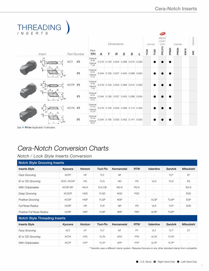
Þ : U.S. Stock Å : Right-Hand Only Ä : Left-Hand Only
Insert Part Number
Dimensions Cermet
MEGACOATCVD Carbide C
eram
ic
Pitch
TPI A T R E S L TC40
TC60
PR
1215
PR
660
PR
930
KW
10
A65
E G
L
R
55°
A
60°
S
T
0°
KCT 2§External
8-36Internal7-20
0.219 0.150 0.004 0.266 0.075 0.350 Þ Þ Þ
3§External
6-20Internal5-12
0.344 0.195 0.007 0.400 0.098 0.634 Þ Þ Þ
E G
L
AT60°S
55°
R
5°
KCTP 2§External
8-36Internal7-20
0.219 0.150 0.004 0.266 0.075 0.350 Þ Þ Þ
3§External
6-20Internal5-12
0.344 0.195 0.007 0.400 0.098 0.634 Þ Þ Þ
E G
L
5°
R
55°
A
60°
S
T KCTK 2§External14-44Internal12-24
0.219 0.150 0.003 0.268 0.110 0.350 Þ Þ Þ
3§External10-44Internal9-24
0.344 0.195 0.003 0.402 0.141 0.634 Þ Þ Þ
THREADINGI N S E R T S
Cera-Notch Conversion ChartsNotch / Lock Style Inserts Conversion
Cera-Notch Inserts
Notch Style Grooving Inserts
Inserts Style Kyocera Horizon Tool-Flo Kennametal RTW Valentine Sandvik Mitsubishi
Face Grooving KCFP HF FLF NF - - TLF* EF
ID or OD Grooving KCG / KCGP HG FLG NG PG VLG TLG* EG
With Chipbreaker KCGP-MY HG-K FLG CB NG-K PG-K - - EG-K
Deep Grooving KCGDP HGD FLGD NGD PGD - - EGD
Positive Grooving KCGP HGP FLGP NGP - VLGP TLGP* EGP
Full Nose Radius KCRP HR FLR NR PR VLR TLR* EGR
Positive Full Nose Radius KCRP HRP FLRP NRP PRP VLRP TLRP* -
Notch Style Threading Inserts
Inserts Style Kyocera Horizon Tool-Flo Kennametal RTW Valentine Sandvik Mitsubishi
Face Grooving KCT HT FLT NT PT VLT TLT* ET
ID or OD Grooving KCTK HTK FLTK NTK PTK VLTK TLTK* -
With Chipbreaker KCTP HTP FLTP NTP PTP VLTP TLTP* -
* Sandvik uses a different clamp system. Requires Kyocera or any other standard clamp from competitor
See � P5 for Applicable Toolhoders
8
Þ : U.S. Stock
Cera-Notch Toolholders
3°3°
BB
F2
L2 L2 L1
T T
H1 H1
H3
H2
H3
h h
Fig.1 Fig.2
F1 F1
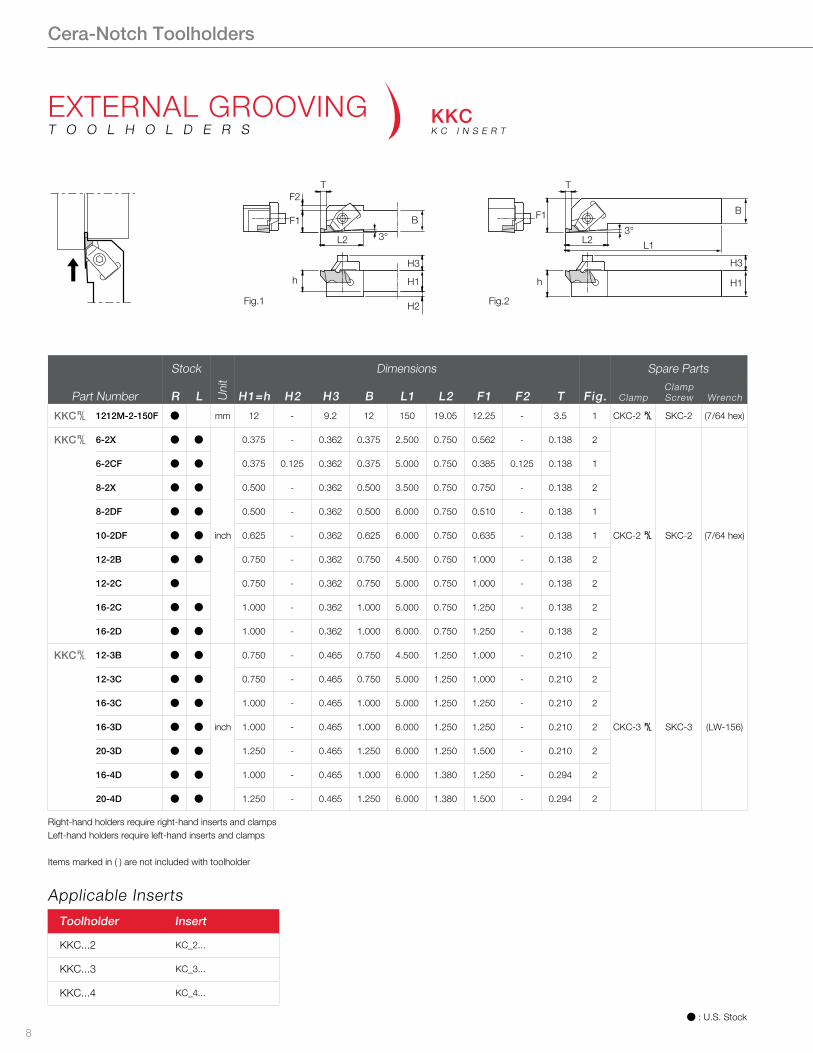
Part Number
Stock
Uni
t
Dimensions
Fig.
Spare Parts
R L H1=h H2 H3 B L1 L2 F1 F2 T ClampClamp Screw Wrench
KKC§ 1212M-2-150F Þ mm 12 - 9.2 12 150 19.05 12.25 - 3.5 1 CKC-2 § SKC-2 (7/64 hex)
KKC§ 6-2X Þ Þ
inch
0.375 - 0.362 0.375 2.500 0.750 0.562 - 0.138 2
CKC-2 § SKC-2 (7/64 hex)
6-2CF Þ Þ 0.375 0.125 0.362 0.375 5.000 0.750 0.385 0.125 0.138 1
8-2X Þ Þ 0.500 - 0.362 0.500 3.500 0.750 0.750 - 0.138 2
8-2DF Þ Þ 0.500 - 0.362 0.500 6.000 0.750 0.510 - 0.138 1
10-2DF Þ Þ 0.625 - 0.362 0.625 6.000 0.750 0.635 - 0.138 1
12-2B Þ Þ 0.750 - 0.362 0.750 4.500 0.750 1.000 - 0.138 2
12-2C Þ 0.750 - 0.362 0.750 5.000 0.750 1.000 - 0.138 2
16-2C Þ Þ 1.000 - 0.362 1.000 5.000 0.750 1.250 - 0.138 2
16-2D Þ Þ 1.000 - 0.362 1.000 6.000 0.750 1.250 - 0.138 2
KKC§ 12-3B Þ Þ
inch
0.750 - 0.465 0.750 4.500 1.250 1.000 - 0.210 2
CKC-3 § SKC-3 (LW-156)
12-3C Þ Þ 0.750 - 0.465 0.750 5.000 1.250 1.000 - 0.210 2
16-3C Þ Þ 1.000 - 0.465 1.000 5.000 1.250 1.250 - 0.210 2
16-3D Þ Þ 1.000 - 0.465 1.000 6.000 1.250 1.250 - 0.210 2
20-3D Þ Þ 1.250 - 0.465 1.250 6.000 1.250 1.500 - 0.210 2
16-4D Þ Þ 1.000 - 0.465 1.000 6.000 1.380 1.250 - 0.294 2
20-4D Þ Þ 1.250 - 0.465 1.250 6.000 1.380 1.500 - 0.294 2
EXTERNAL GROOVINGT O O L H O L D E R S
KKCK C I N S E R T
Right-hand holders require right-hand inserts and clampsLeft-hand holders require left-hand inserts and clamps
Items marked in ( ) are not included with toolholder
Toolholder Insert
KKC...2 KC_2...
KKC...3 KC_3...
KKC...4 KC_4...
Applicable Inserts
9
Þ : U.S. Stock
Cera-Notch Toolholders
F1
L2 T
L1
B
L3
H3
H1h
3°
35°
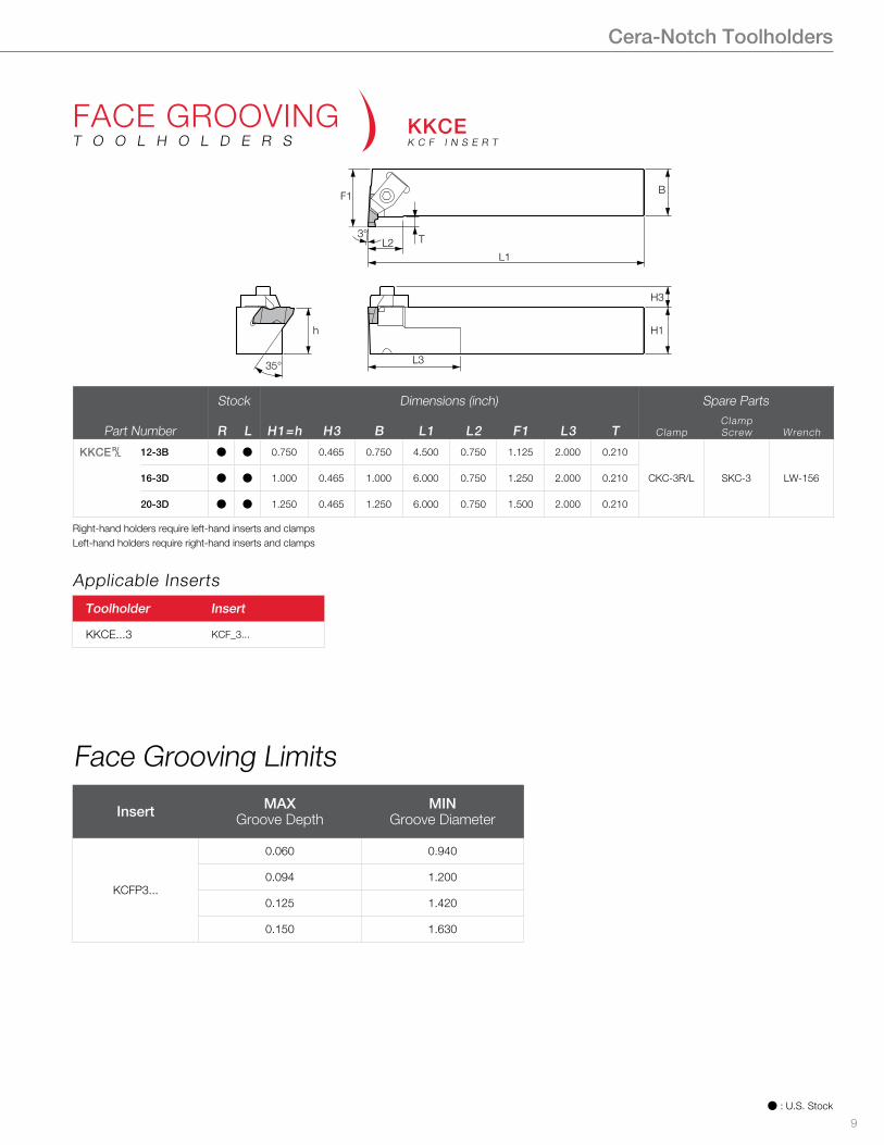
Part Number
Stock Dimensions (inch) Spare Parts
R L H1=h H3 B L1 L2 F1 L3 T ClampClamp Screw Wrench
KKCE§ 12-3B Þ Þ 0.750 0.465 0.750 4.500 0.750 1.125 2.000 0.210
CKC-3R/L SKC-3 LW-15616-3D Þ Þ 1.000 0.465 1.000 6.000 0.750 1.250 2.000 0.210
20-3D Þ Þ 1.250 0.465 1.250 6.000 0.750 1.500 2.000 0.210
FACE GROOVINGT O O L H O L D E R S
KKCEK C F I N S E R T
Right-hand holders require left-hand inserts and clampsLeft-hand holders require right-hand inserts and clamps
Toolholder Insert
KKCE...3 KCF_3...
Insert MAXGroove Depth
MINGroove Diameter
KCFP3...
0.060 0.940
0.094 1.200
0.125 1.420
0.150 1.630
Applicable Inserts
Face Grooving Limits
10
Þ : U.S. Stock
Cera-Notch Toolholders
ØA3°
L2 HL1
G
ØD
F
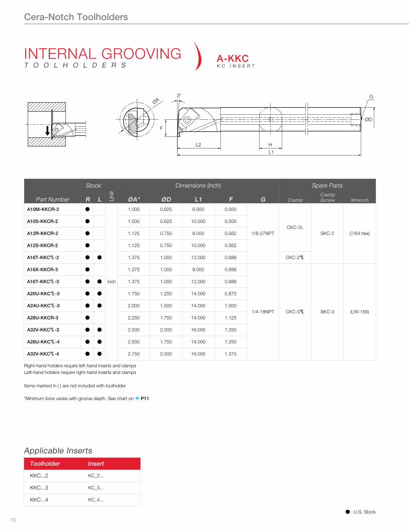
Part Number
Stock
Uni
t
Dimensions (inch) Spare Parts
R L ØA* ØD L1 F G ClampClampScrew Wrench
A10M-KKCR-2 Þ
inch
1.000 0.625 6.000 0.500
1/8-27NPTCKC-2L
SKC-2 (7/64 hex)
A10S-KKCR-2 Þ 1.000 0.625 10.000 0.500
A12R-KKCR-2 Þ 1.125 0.750 8.000 0.562
A12S-KKCR-2 Þ 1.125 0.750 10.000 0.562
A16T-KKC§-2 Þ Þ 1.375 1.000 12.000 0.688 CKC-2§
A16X-KKCR-3 Þ 1.375 1.000 9.000 0.688
1/4-18NPT CKC-3§ SKC-3 (LW-156)
A16T-KKC§-3 Þ Þ 1.375 1.000 12.000 0.688
A20U-KKC§-3 Þ Þ 1.750 1.250 14.000 0.875
A24U-KKC§-3 Þ Þ 2.000 1.500 14.000 1.000
A28U-KKCR-3 Þ 2.250 1.750 14.000 1.125
A32V-KKC§-3 Þ Þ 2.500 2.000 16.000 1.250
A28U-KKC§-4 Þ Þ 2.500 1.750 14.000 1.250
A32V-KKC§-4 Þ Þ 2.750 2.000 16.000 1.375
INTERNAL GROOVINGT O O L H O L D E R S
A-KKCK C I N S E R T
Right-hand holders require left-hand inserts and clampsLeft-hand holders require right-hand inserts and clamps
Items marked in ( ) are not included with toolholder
Toolholder Insert
KKC...2 KC_2...
KKC...3 KC_3...
KKC...4 KC_4...
Applicable Inserts
*Minimum bore varies with groove depth. See chart on � P11
11
Cera-Notch Toolholders
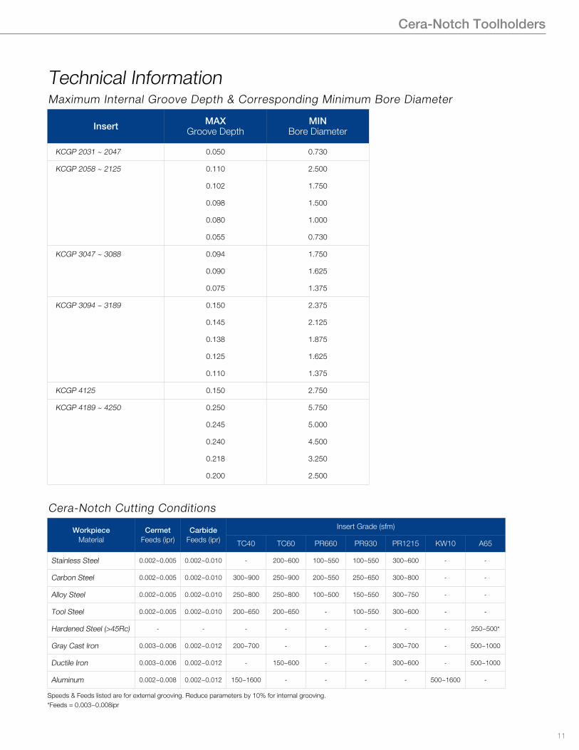
Speeds & Feeds listed are for external grooving. Reduce parameters by 10% for internal grooving.*Feeds = 0.003~0.008ipr
Technical InformationMaximum Internal Groove Depth & Corresponding Minimum Bore Diameter
Cera-Notch Cutting Conditions
Insert MAXGroove Depth
MINBore Diameter
KCGP 2031 ~ 2047 0.050 0.730
KCGP 2058 ~ 2125 0.110 2.500
0.102 1.750
0.098 1.500
0.080 1.000
0.055 0.730
KCGP 3047 ~ 3088 0.094 1.750
0.090 1.625
0.075 1.375
KCGP 3094 ~ 3189 0.150 2.375
0.145 2.125
0.138 1.875
0.125 1.625
0.110 1.375
KCGP 4125 0.150 2.750
KCGP 4189 ~ 4250 0.250 5.750
0.245 5.000
0.240 4.500
0.218 3.250
0.200 2.500
WorkpieceMaterial
CermetFeeds (ipr)
CarbideFeeds (ipr)
Insert Grade (sfm)
TC40 TC60 PR660 PR930 PR1215 KW10 A65
Stainless Steel 0.002~0.005 0.002~0.010 - 200~600 100~550 100~550 300~600 - -
Carbon Steel 0.002~0.005 0.002~0.010 300~900 250~900 200~550 250~650 300~800 - -
Alloy Steel 0.002~0.005 0.002~0.010 250~800 250~800 100~500 150~550 300~750 - -
Tool Steel 0.002~0.005 0.002~0.010 200~650 200~650 - 100~550 300~600 - -
Hardened Steel (>45Rc) - - - - - - - - 250~500*
Gray Cast Iron 0.003~0.006 0.002~0.012 200~700 - - - 300~700 - 500~1000
Ductile Iron 0.003~0.006 0.002~0.012 - 150~600 - - 300~600 - 500~1000
Aluminum 0.002~0.008 0.002~0.012 150~1600 - - - - 500~1600 -
©KYOCERA Precision Tools, Inc.10/14, 5K Printed in U.S.A.
KYOCERA Precision Tools, Inc.102 Industrial Park RoadHendersonville, NC 28792Customer Service | 800.823.7284 - Option 1Technical Support | 800.823.7284 - Option 2
W | Official Website | www.kyoceraprecisiontools.comW | Distributor Website | http://mykpti.kyocera.comE | [email protected]