Embed Size (px)
Citation preview
B
CEP
7 Ov
erlo
ads
B2visit www.sprecherschuh.com/ecatalog for pricing and the most up to date information SSNA2018www.sprecherschuh.com/ecatalog - All pricing shown in US dollars - FY20
CEP7 Solid State Overload Relays
Advanced solid state motor protectionThe CEP7 solid state overload relay in-cludes advanced technology with several key features like:• Selectable trip class and field
installable modules• A wide (5:1) set current
adjustment range• A robust mechanical and
electrical mounting• Self-sealed latching mechanismThe basic concept of utilizing Applica-tion Specific Integrated Circuits (ASICs) results in an affordable solid state overload relay. This kind of versatility and accuracy is simply not possible with traditional bimetallic or eutectic alloy electromechanical overload relays.
Fewer units means greater application flexibilityThe CEP7 Soild State Overload Relay is available in three basic models:• CEP7-ED1 is a Class 10, manual reset
model available up to 45 amperes which covers the most common horsepower motors and your every day application. This model is eco-nomically priced to be competitive with adjustable bimetallic overload relays.
• CEP7-EE is a full featured selectable trip class (10, 15, 20 & 30) 3-phase application overload relay with provi-sion for field mountable modules to handle remote reset, jam protection, and other modules previously avail-able only in higher priced electronic overload relays.
Manual reset or automatic reset can be selected with dip switches on the CEP7-EE models.
• CEP7S-EE is a 1-phase application overload relay packing all features of the 3-phase CEP7-EE model.
Wide current adjustment rangeThermal or bimetallic overload relays typically have a small current adjust-ment range of 1.5:1 meaning that the maximum setting is generally 1.5 times the lower setting. The CEP7 caused the industry to take note of the flexibility when it first introduced a 3.2:1 adjust-ment ratio. A wider adjustment range is the primary reason the industry has been turning to more specifications calling for electronic overload relay protection over thermal overload relays. Sprecher + Schuh’s CEP7 overload relay is capable of adjustment to a maximum of five times the minimum set current, which dramatically reduces the number of units required on-hand to cover the full range of current settings up to 200 amperes.
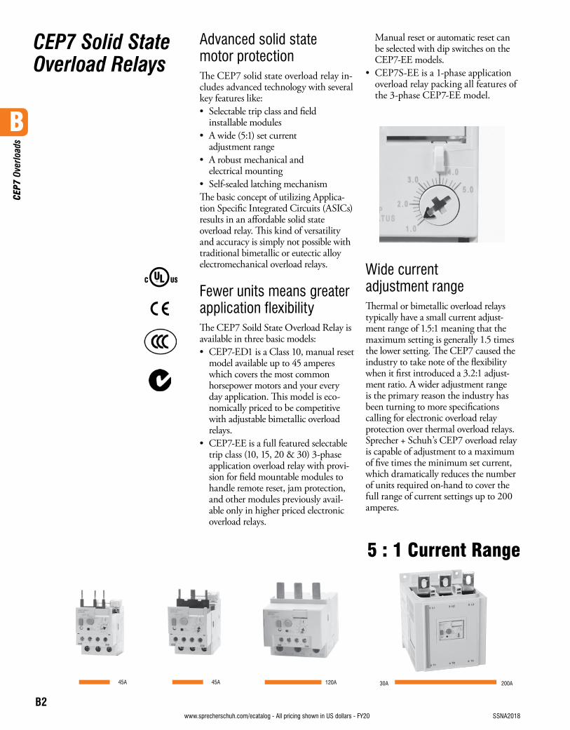
45A 120A 200A30A
5 : 1 Current Range
45A
B
CEP
7 Ov
erlo
ads
B3visit www.sprecherschuh.com/ecatalog for pricing and the most up to date informationSSNA2018 www.sprecherschuh.com/ecatalog - All pricing shown in US dollars - FY20
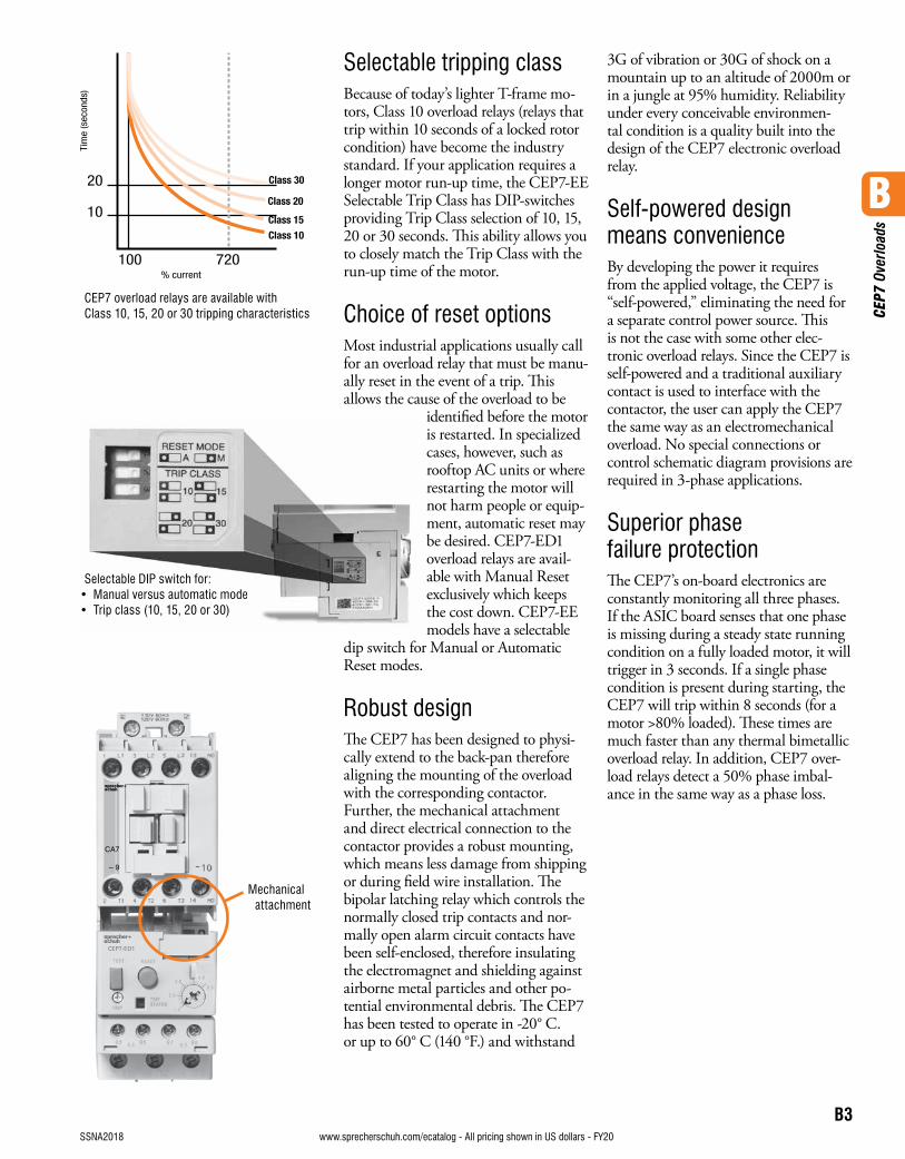
Selectable tripping classBecause of today’s lighter T-frame mo-tors, Class 10 overload relays (relays that trip within 10 seconds of a locked rotor condition) have become the industry standard. If your application requires a longer motor run-up time, the CEP7-EE Selectable Trip Class has DIP-switches providing Trip Class selection of 10, 15, 20 or 30 seconds. This ability allows you to closely match the Trip Class with the run-up time of the motor.
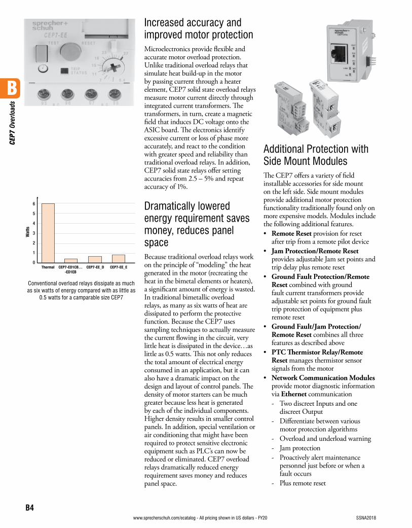
Choice of reset optionsMost industrial applications usually call for an overload relay that must be manu-ally reset in the event of a trip. This allows the cause of the overload to be
identified before the motor is restarted. In specialized cases, however, such as rooftop AC units or where restarting the motor will not harm people or equip-ment, automatic reset may be desired. CEP7-ED1 overload relays are avail-able with Manual Reset exclusively which keeps the cost down. CEP7-EE models have a selectable
dip switch for Manual or Automatic Reset modes.
Robust designThe CEP7 has been designed to physi-cally extend to the back-pan therefore aligning the mounting of the overload with the corresponding contactor. Further, the mechanical attachment and direct electrical connection to the contactor provides a robust mounting, which means less damage from shipping or during field wire installation. The bipolar latching relay which controls the normally closed trip contacts and nor-mally open alarm circuit contacts have been self-enclosed, therefore insulating the electromagnet and shielding against airborne metal particles and other po-tential environmental debris. The CEP7 has been tested to operate in -20° C. or up to 60° C (140 °F.) and withstand
3G of vibration or 30G of shock on a mountain up to an altitude of 2000m or in a jungle at 95% humidity. Reliability under every conceivable environmen-tal condition is a quality built into the design of the CEP7 electronic overload relay.
Self-powered design means convenienceBy developing the power it requires from the applied voltage, the CEP7 is “self-powered,” eliminating the need for a separate control power source. This is not the case with some other elec-tronic overload relays. Since the CEP7 is self-powered and a traditional auxiliary contact is used to interface with the contactor, the user can apply the CEP7 the same way as an electromechanical overload. No special connections or control schematic diagram provisions are required in 3-phase applications.
Superior phase failure protectionThe CEP7’s on-board electronics are constantly monitoring all three phases. If the ASIC board senses that one phase is missing during a steady state running condition on a fully loaded motor, it will trigger in 3 seconds. If a single phase condition is present during starting, the CEP7 will trip within 8 seconds (for a motor >80% loaded). These times are much faster than any thermal bimetallic overload relay. In addition, CEP7 over-load relays detect a 50% phase imbal-ance in the same way as a phase loss.
CEP7 overload relays are available with Class 10, 15, 20 or 30 tripping characteristics
Selectable DIP switch for:• Manual versus automatic mode• Trip class (10, 15, 20 or 30)
Mechanical attachment
B
CEP
7 Ov
erlo
ads
B4visit www.sprecherschuh.com/ecatalog for pricing and the most up to date information SSNA2018www.sprecherschuh.com/ecatalog - All pricing shown in US dollars - FY20
Additional Protection with Side Mount ModulesThe CEP7 offers a variety of field installable accessories for side mount on the left side. Side mount modules provide additional motor protection functionality traditionally found only on more expensive models. Modules include the following additional features.• Remote Reset provision for reset
after trip from a remote pilot device• Jam Protection/Remote Reset
provides adjustable Jam set points and trip delay plus remote reset
• Ground Fault Protection/Remote Reset combined with ground fault current transformers provide adjustable set points for ground fault trip protection of equipment plus remote reset
• Ground Fault/Jam Protection/Remote Reset combines all three features as described above
• PTC Thermistor Relay/Remote Reset manages thermistor sensor signals from the motor
• Network Communication Modules provide motor diagnostic information via Ethernet communication- Two discreet Inputs and one
discreet Output- Differentiate between various
motor protection algorithms- Overload and underload warning- Jam protection- Proactively alert maintenance
personnel just before or when a fault occurs
- Plus remote reset
Thermal CEP7-ED1CB… CEP7-EE_D CEP7-EE_E -ED1EB
6
5
4
3
2
1
0
Wat
ts
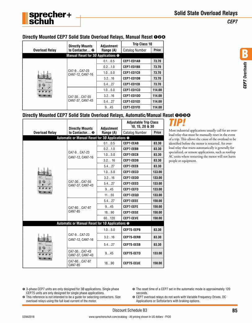
Conventional overload relays dissipate as much as six watts of energy compared with as little as
0.5 watts for a camparable size CEP7
Increased accuracy and improved motor protectionMicroelectronics provide flexible and accurate motor overload protection. Unlike traditional overload relays that simulate heat build-up in the motor by passing current through a heater element, CEP7 solid state overload relays measure motor current directly through integrated current transformers. The transformers, in turn, create a magnetic field that induces DC voltage onto the ASIC board. The electronics identify excessive current or loss of phase more accurately, and react to the condition with greater speed and reliability than traditional overload relays. In addition, CEP7 solid state relays offer setting accuracies from 2.5 – 5% and repeat accuracy of 1%.
Dramatically lowered energy requirement saves money, reduces panel spaceBecause traditional overload relays work on the principle of “modeling” the heat generated in the motor (recreating the heat in the bimetal elements or heaters), a significant amount of energy is wasted. In traditional bimetallic overload relays, as many as six watts of heat are dissipated to perform the protective function. Because the CEP7 uses sampling techniques to actually measure the current flowing in the circuit, very little heat is dissipated in the device…as little as 0.5 watts. This not only reduces the total amount of electrical energy consumed in an application, but it can also have a dramatic impact on the design and layout of control panels. The density of motor starters can be much greater because less heat is generated by each of the individual components. Higher density results in smaller control panels. In addition, special ventilation or air conditioning that might have been required to protect sensitive electronic equipment such as PLC’s can now be reduced or eliminated. CEP7 overload relays dramatically reduced energy requirement saves money and reduces panel space.
B
CEP
7 Ov
erlo
ads
B5visit www.sprecherschuh.com/ecatalog for pricing and the most up to date informationSSNA2018
Discount Schedule B3www.sprecherschuh.com/ecatalog - All pricing shown in US dollars - FY20
Overload RelayDirectly Mounts to Contactor… ➋
Adjustment Range (A)
Adjustable Trip Class 10, 15, 20 & 30
Catalog Number Price
Automatic or Manual Reset for 3Ø Applications ➊
CA7-9…CA7-23
CAN7-12, CAN7-16
0.1…0.5 CEP7-EEAB 83.30
0.2…1.0 CEP7-EEBB 83.30
1.0…5.0 CEP7-EECB 83.30
3.2… 16 CEP7-EEDB 83.30
5.4…27 CEP7-EEEB 83.30
CA7-30…CA7-55CAN7-37, CAN7-43
1.0…5.0 CEP7-EECD 133.00
3.2…16 CEP7-EEDD 133.00
5.4…27 CEP7-EEED 133.00
9…45 CEP7-EEFD 133.00
11…55 CEP7-EEQD 133.00
CA7-60…CA7-97CAN7-85
5.4…27 CEP7-EEEE 150.00
9…45 CEP7-EEFE 150.00
18…90 CEP7-EEGE 150.00
60…120 CEP7-EEVE 150.00
Automatic or Manual Reset for 1Ø Applications ➊
CA7-9…CA7-23
CAN7-12, CAN7-16
1.0…5.0 CEP7S-EEPB 83.30
3.2…16 CEP7S-EERB 83.30
5.4…27 CEP7S-EESB 83.30
CA7-30…CA7-43CAN7-37, CAN7-43 9…45 CEP7S-EETD 133.00
CA7-60…CA7-97CAN7-85 18…90 CEP7S-EEUE 150.00
Solid State Overload RelaysCEP7
Directly Mounted CEP7 Solid State Overload Relays, Manual Reset ➊➋➍
Overload RelayDirectly Mounts to Contactor… ➋
Adjustment Range (A)
Trip Class 10
Catalog Number Price
Manual Reset for 3Ø Applications ➊
CA7-9…CA7-23CAN7-12, CAN7-16
0.1…0.5 CEP7-ED1AB 73.70
0.2…1.0 CEP7-ED1BB 73.70
1.0…5.0 CEP7-ED1CB 73.70
3.2…16 CEP7-ED1DB 73.70
5.4…27 CEP7-ED1EB 73.70
CA7-30…CA7-55CAN7-37, CAN7-43
1.0…5.0 CEP7-ED1CD 114.00
3.2…16 CEP7-ED1DD 114.00
5.4…27 CEP7-ED1ED 114.00
9…45 CEP7-ED1FD 114.00
Directly Mounted CEP7 Solid State Overload Relays, Automatic/Manual Reset ➊➋➌➍
➊ 3-phase CEP7 units are only designed for 3Ø applications. Single phase CEP7S units are only designed for single phase applications.
➋ This reference is not intended to be a guide for selecting contactors. Size overload relays using the full load current of the motor.
➌ The reset time of a CEP7 set in the automatic mode is approximately 120 seconds.
➍ CEP7 overload relays do not work with Variable Frequency Drives, DC Applications or Softstarters with braking options.
Most industrial applications usually call for an over-load relay that must be manually reset in the event of a trip. This allows the cause of the overload to be identified before the motor is restarted. An over-load relay that resets automatically is generally for specialized, or remote applications, such as rooftop AC units where restarting the motor will not harm people or equipment.
TIP!
B
CEP
7 Ov
erlo
ads
B6visit www.sprecherschuh.com/ecatalog for pricing and the most up to date information SSNA2018
Discount Schedule B3www.sprecherschuh.com/ecatalog - All pricing shown in US dollars - FY20
Overload RelaySeparate Mount for use with… ➋
Adjustment Range (A)
Trip Class 10
Catalog Number Price
Manual Reset for 3Ø Applications ➊➍
Fig. 1
CA8-09…12CA7-9…CA7-23CAN7-12…CAN7-37
1.0…5.0 CEP7-ED1CP 73.70
3.2… 16 CEP7-ED1DP 73.70
5.4…27 CEP7-ED1EP 73.70
Overload RelaySeparate Mount for use with… ➋
Adjustment Range (A)
Adjustable Trip Class 10, 15, 20 & 30
Catalog Number Price
Automatic or Manual Reset for 3Ø Applications ➊➌➍
Fig. 1
CA8-09…12
CA7-9…CA7-23
CAN7-12…CAN7-37
1.0…5.0 CEP7-EECP 79.10
3.2… 16 CEP7-EEDP 79.10
5.4…27 CEP7-EEEP 79.10
Automatic or Manual Reset for 1Ø Applications ➊➌➍
Fig. 1
CA8-09…12
CA7-9…CA7-23
CAN7-12…CAN7-37
1.0…5.0 CEP7S-EEPP 79.10
3.2…16 CEP7S-EERP 79.10
5.4…27 CEP7S-EESP 79.10
Solid State Overload RelaysCEP7
Pass-Thru CEP7 Solid State Overload Relays ➎
➊ 3-phase CEP7 units are only designed for 3Ø applications. Single phase CEP7S units are only designed for single phase applications.
➋ This reference is not intended to be a guide for selecting contactors. Size overload relays using the full load current of the motor.
➌ The reset time of a CEP7 set in the automatic mode is approximately 120 seconds.➍ CEP7 overload relays do not work with Variable Frequency Drives, DC Applications or
Softstarters with braking options.➎ Pass-Thru windows will accept one power wire up to #10 AWG wire (6mm2).
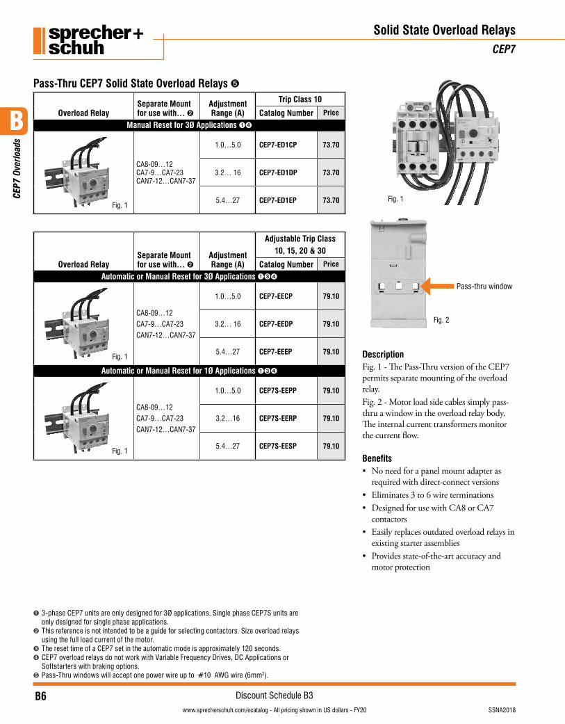
Description Fig. 1 - The Pass-Thru version of the CEP7 permits separate mounting of the overload relay. Fig. 2 - Motor load side cables simply pass-thru a window in the overload relay body. The internal current transformers monitor the current flow.
Benefits• No need for a panel mount adapter as
required with direct-connect versions• Eliminates 3 to 6 wire terminations• Designed for use with CA8 or CA7
contactors• Easily replaces outdated overload relays in
existing starter assemblies• Provides state-of-the-art accuracy and
motor protection
Pass-thru window
Fig. 2
Fig. 1
B
CEP
7 Ov
erlo
ads
B7visit www.sprecherschuh.com/ecatalog for pricing and the most up to date informationSSNA2018
Discount Schedule B3www.sprecherschuh.com/ecatalog - All pricing shown in US dollars - FY20
Solid State Overload Relays & AccessoriesCEP7
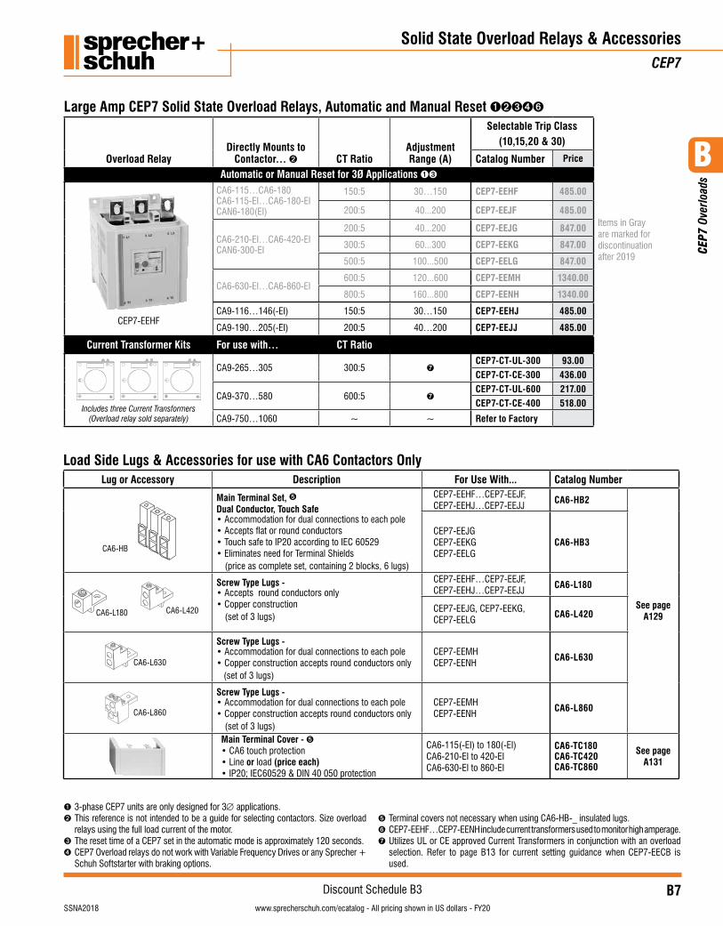
Large Amp CEP7 Solid State Overload Relays, Automatic and Manual Reset ➊➋➌➍➏
Overload RelayDirectly Mounts to
Contactor… ➋ CT RatioAdjustment Range (A)
Selectable Trip Class (10,15,20 & 30)
Items in Gray are marked for discontinuation after 2019
Catalog Number Price
Automatic or Manual Reset for 3Ø Applications ➊➌
CEP7-EEHF
CA6-115…CA6-180CA6-115-EI…CA6-180-EICAN6-180(EI)
150:5 30…150 CEP7-EEHF 485.00
200:5 40...200 CEP7-EEJF 485.00
CA6-210-EI…CA6-420-EICAN6-300-EI
200:5 40...200 CEP7-EEJG 847.00
300:5 60...300 CEP7-EEKG 847.00
500:5 100...500 CEP7-EELG 847.00
CA6-630-EI…CA6-860-EI600:5 120...600 CEP7-EEMH 1340.00
800:5 160...800 CEP7-EENH 1340.00
CA9-116…146(-EI) 150:5 30…150 CEP7-EEHJ 485.00
CA9-190…205(-EI) 200:5 40…200 CEP7-EEJJ 485.00
Current Transformer Kits For use with… CT Ratio
Includes three Current Transformers (Overload relay sold separately)
CA9-265…305 300:5 ➐CEP7-CT-UL-300 93.00CEP7-CT-CE-300 436.00
CA9-370…580 600:5 ➐CEP7-CT-UL-600 217.00CEP7-CT-CE-400 518.00
CA9-750…1060 ~ ~ Refer to Factory
➊ 3-phase CEP7 units are only designed for 3∅ applications.➋ This reference is not intended to be a guide for selecting contactors. Size overload
relays using the full load current of the motor.➌ The reset time of a CEP7 set in the automatic mode is approximately 120 seconds.➍ CEP7 Overload relays do not work with Variable Frequency Drives or any Sprecher +
Schuh Softstarter with braking options.
➎ Terminal covers not necessary when using CA6-HB-_ insulated lugs.➏ CEP7-EEHF…CEP7-EENH include current transformers used to monitor high amperage. ➐ Utilizes UL or CE approved Current Transformers in conjunction with an overload
selection. Refer to page B13 for current setting guidance when CEP7-EECB is used.
Load Side Lugs & Accessories for use with CA6 Contactors Only Lug or Accessory Description For Use With... Catalog Number
CA6-HB
Main Terminal Set, ➎Dual Conductor, Touch Safe• Accommodation for dual connections to each pole• Accepts flat or round conductors• Touch safe to IP20 according to IEC 60529• Eliminates need for Terminal Shields
(price as complete set, containing 2 blocks, 6 lugs)
CEP7-EEHF…CEP7-EEJF,CEP7-EEHJ…CEP7-EEJJ
CA6-HB2
See page A129
CEP7-EEJGCEP7-EEKGCEP7-EELG
CA6-HB3
CA6-L180 CA6-L420
Screw Type Lugs -• Accepts round conductors only• Copper construction
(set of 3 lugs)
CEP7-EEHF…CEP7-EEJF,CEP7-EEHJ…CEP7-EEJJ
CA6-L180
CEP7-EEJG, CEP7-EEKG, CEP7-EELG
CA6-L420
CA6-L630
Screw Type Lugs -• Accommodation for dual connections to each pole• Copper construction accepts round conductors only
(set of 3 lugs)
CEP7-EEMHCEP7-EENH
CA6-L630
CA6-L860
Screw Type Lugs -• Accommodation for dual connections to each pole• Copper construction accepts round conductors only
(set of 3 lugs)
CEP7-EEMHCEP7-EENH
CA6-L860
Main Terminal Cover - ➎• CA6 touch protection• Line or load (price each)• IP20; IEC60529 & DIN 40 050 protection
CA6-115(-EI) to 180(-EI) CA6-210-EI to 420-EI CA6-630-EI to 860-EI
CA6-TC180 CA6-TC420 CA6-TC860
See page A131
B
CEP
7 Ov
erlo
ads
B8visit www.sprecherschuh.com/ecatalog for pricing and the most up to date information SSNA2018
Discount Schedule B3www.sprecherschuh.com/ecatalog - All pricing shown in US dollars - FY20
Accessories – Field InstallableCEP7 Solid State Overload Relays
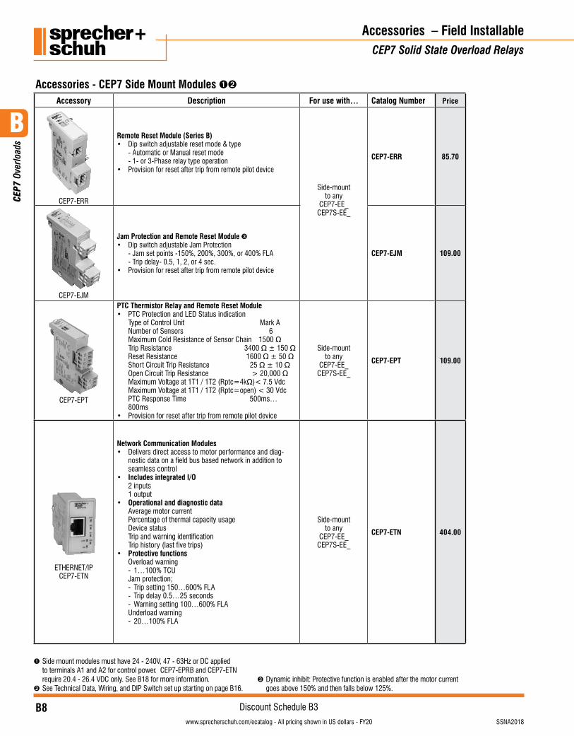
Accessories - CEP7 Side Mount Modules ➊➋
Accessory Description For use with… Catalog Number Price
CEP7-ERR
Remote Reset Module (Series B)• Dip switch adjustable reset mode & type - Automatic or Manual reset mode - 1- or 3-Phase relay type operation• Provision for reset after trip from remote pilot device
Side-mountto any
CEP7-EE_CEP7S-EE_
CEP7-ERR 85.70
CEP7-EJM
Jam Protection and Remote Reset Module ➌• Dip switch adjustable Jam Protection - Jam set points -150%, 200%, 300%, or 400% FLA - Trip delay- 0.5, 1, 2, or 4 sec.• Provision for reset after trip from remote pilot device
CEP7-EJM 109.00
CEP7-EPT
PTC Thermistor Relay and Remote Reset Module• PTC Protection and LED Status indication Type of Control Unit Mark A Number of Sensors 6 Maximum Cold Resistance of Sensor Chain 1500 Ω Trip Resistance 3400 Ω ± 150 Ω Reset Resistance 1600 Ω ± 50 Ω Short Circuit Trip Resistance 25 Ω ± 10 Ω Open Circuit Trip Resistance > 20,000 Ω Maximum Voltage at 1T1 / 1T2 (Rptc=4kΩ) < 7.5 Vdc Maximum Voltage at 1T1 / 1T2 (Rptc=open) < 30 Vdc PTC Response Time 500ms…
800ms• Provision for reset after trip from remote pilot device
Side-mountto any
CEP7-EE_CEP7S-EE_
CEP7-EPT 109.00
ETHERNET/IP CEP7-ETN
Network Communication Modules• Delivers direct access to motor performance and diag-
nostic data on a field bus based network in addition to seamless control
• Includes integrated I/O 2 inputs
1 output• Operational and diagnostic data
Average motor current Percentage of thermal capacity usage Device status Trip and warning identification Trip history (last five trips)
• Protective functions Overload warning - 1…100% TCU Jam protection; - Trip setting 150…600% FLA - Trip delay 0.5…25 seconds - Warning setting 100…600% FLA Underload warning - 20…100% FLA
Side-mountto any
CEP7-EE_CEP7S-EE_
CEP7-ETN 404.00
➊ Side mount modules must have 24 - 240V, 47 - 63Hz or DC applied to terminals A1 and A2 for control power. CEP7-EPRB and CEP7-ETN require 20.4 - 26.4 VDC only. See B18 for more information.
➋ See Technical Data, Wiring, and DIP Switch set up starting on page B16.➌ Dynamic inhibit: Protective function is enabled after the motor current
goes above 150% and then falls below 125%.
B
CEP
7 Ov
erlo
ads
B9visit www.sprecherschuh.com/ecatalog for pricing and the most up to date informationSSNA2018
Discount Schedule B3www.sprecherschuh.com/ecatalog - All pricing shown in US dollars - FY20
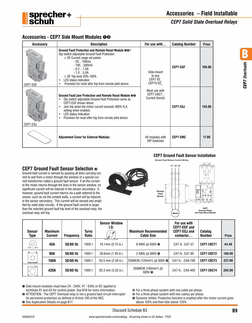
CEP7 Ground Fault Sensor Selection ➌Ground fault current is sensed by passing all lines carrying cur-rent to and from a motor through the window of a special cur-rent transformer called a ground fault sensor. If all the current to the motor returns through the lines in the sensor window, no significant current will be induced in the sensor secondary. If, however, ground fault current returns via a path external to the sensor, such as via the conduit walls, a current will be induced in the sensor secondary. This current will be sensed and ampli-fied by solid state circuits. If the ground fault current is larger than the selected ground fault trip level of the overload relay, the overload relay will trip.
Sensor Type
Maximum Current Frequency
Turns Ratio
Sensor Window I.D.
Maximum Recommended Cable Size
For use with CEP7-EGF and CEP7-EGJ and contactor…
Catalog Number Price
45A 50/60 Hz 1000:1 19.1mm (0.75 in.) 8 AWG @ 600V ➍ CA7-9...CA7-37 CEP7-CBCT1 44.40
90A 50/60 Hz 1000:1 39.6mm (1.56 in.) 2 AWG @ 600V ➍ CA7-9...CA7-85 CEP7-CBCT2 168.00
180A 50/60 Hz 1000:1 63.5 mm (2.50 in.) 250MCM (120mm2) @ 600V ➍ CA7-9…CA9-190 CEP7-CBCT3 227.00
420A 50/60 Hz 1000:1 82.3 mm (3.25 in.) 350MCM (185mm2) @ 600V ➎ CA7-9…CA9-400 CEP7-CBCT4 284.00
Accessory Description For use with… Catalog Number Price
CEP7-EGF
Ground Fault Protection and Remote Reset Module ➋➏• Dip switch adjustable Ground Fault Protection > GF Current range set points - 20…100ma - 100…500mA - 0.2…1.0A - 1.0…5.0A > GF Trip level 20%-100%• LED status indication• Provision for reset after trip from remote pilot device
Side-mountto any
CEP7-EE_CEP7S-EE_
Must use withCEP7-CBCT_
Current Sensor
CEP7-EGF 109.00
CEP7-EGJ
Ground Fault/Jam Protection and Remote Reset Module ➋➏• Dip switch adjustable Ground Fault Protection same as CEP7-EGF shown above.• Jam trip when the motor current exceeds 400% FLA setting when enabled.• LED status indication• Provision for reset after trip from remote pilot device
CEP7-EGJ 145.00
Adjustment Cover for External Modules All modules withDIP Switches
CEP7-EMC 17.90
Accessories – Field InstallableCEP7 Solid State Overload Relays
Accessories - CEP7 Side Mount Modules ➊➌
➊ Side mount modules must have 24 - 240V, 47 - 63Hz or DC applied to terminals A1 and A2 for control power. See B18 for more information.
➋ ATTENTION: The CEP7 Overload relay is not a ground fault circuit interrupter for personnel protection as defined in Article 100 of the NEC.
➌ See Application Details on page B17.
➍ For a three phase system with one cable per phase.➎ For a three phase system with two cables per phase.➏ Dynamic inhibit: Protective function is enabled after the motor current goes
above 150% and then falls below 125%.
CEP7 Ground Fault Sensor InstallationGround Fault Sensor Control Wiring
Motor
L2 L3L1
GroundFault
Sensor
CEP7Overload Relay
with Side Mount Module
S1 S2
B
CEP
7 Ov
erlo
ads
B10visit www.sprecherschuh.com/ecatalog for pricing and the most up to date information SSNA2018
Discount Schedule B3www.sprecherschuh.com/ecatalog - All pricing shown in US dollars - FY20
Accessories – Field InstallableCEP7 Solid State Overload Relays
➊ CEP7-ERA does not fit CEP7-EE_J units without removing the CEP7 cover.➋ Solenoid Reset Modules only mount on CEP7 Series C or later.➌ See page B21 for additional details on installation and LED functions.
➍ Coil consumption of AC coils is 8VA.➎ Coil consumption of DC coils is 12 watts.
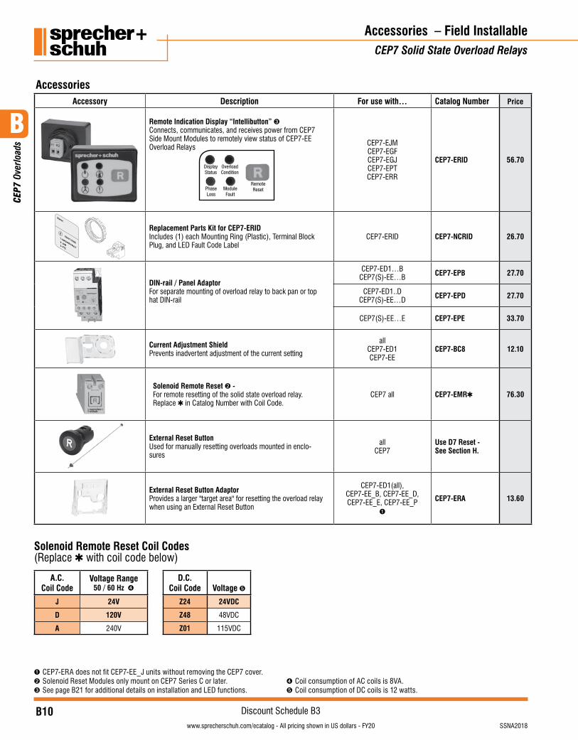
AccessoriesAccessory Description For use with… Catalog Number Price
Remote Indication Display “Intellibutton” ➌Connects, communicates, and receives power from CEP7 Side Mount Modules to remotely view status of CEP7-EE Overload Relays CEP7-EJM
CEP7-EGFCEP7-EGJCEP7-EPTCEP7-ERR
CEP7-ERID 56.70
FAULT CODE
Starter:
1- GROUND FAULT
2- JAM 3- PTC
Replacement Parts Kit for CEP7-ERIDIncludes (1) each Mounting Ring (Plastic), Terminal Block Plug, and LED Fault Code Label
CEP7-ERID CEP7-NCRID 26.70
DIN-rail / Panel AdaptorFor separate mounting of overload relay to back pan or top hat DIN-rail
CEP7-ED1…BCEP7(S)-EE…B CEP7-EPB 27.70
CEP7-ED1..DCEP7(S)-EE…D CEP7-EPD 27.70
CEP7(S)-EE…E CEP7-EPE 33.70
Current Adjustment ShieldPrevents inadvertent adjustment of the current setting
allCEP7-ED1CEP7-EE
CEP7-BC8 12.10
Solenoid Remote Reset ➋ -For remote resetting of the solid state overload relay. Replace ✱ in Catalog Number with Coil Code.
CEP7 all CEP7-EMR✱ 76.30
External Reset ButtonUsed for manually resetting overloads mounted in enclo-sures
allCEP7
Use D7 Reset -See Section H.
External Reset Button AdaptorProvides a larger "target area" for resetting the overload relay when using an External Reset Button
CEP7-ED1(all),CEP7-EE_B, CEP7-EE_D, CEP7-EE_E, CEP7-EE_P
➊
CEP7-ERA 13.60
Solenoid Remote Reset Coil Codes (Replace ✱ with coil code below)
A.C.Coil Code
Voltage Range50 / 60 Hz ➍
D.C.Coil Code Voltage ➎
J 24V Z24 24VDC
D 120V Z48 48VDC
A 240V Z01 115VDC
B
CEP
7 Ov
erlo
ads
B11visit www.sprecherschuh.com/ecatalog for pricing and the most up to date informationSSNA2018
Discount Schedule B3www.sprecherschuh.com/ecatalog - All pricing shown in US dollars - FY20
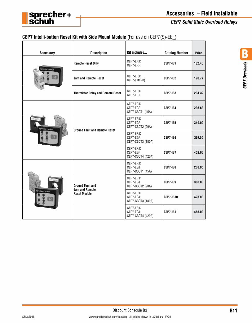
Accessory Description Kit includes... Catalog Number Price
Remote Reset Only CEP7-ERIDCEP7-ERR
CEP7-IB1 182.43
Jam and Remote Reset CEP7-ERIDCEP7-EJM (B)
CEP7-IB2 190.77
Thermistor Relay and Remote Reset CEP7-ERIDCEP7-EPT
CEP7-IB3 204.32
Ground Fault and Remote Reset
CEP7-ERIDCEP7-EGFCEP7-CBCT1 (45A)
CEP7-IB4 236.63
CEP7-ERIDCEP7-EGFCEP7-CBCT2 (90A)
CEP7-IB5 349.00
CEP7-ERIDCEP7-EGFCEP7-CBCT3 (180A)
CEP7-IB6 397.00
CEP7-ERIDCEP7-EGFCEP7-CBCT4 (420A)
CEP7-IB7 452.00
Ground Fault and Jam and Remote Reset Module
CEP7-ERIDCEP7-EGJCEP7-CBCT1 (45A)
CEP7-IB8 268.95
CEP7-ERIDCEP7-EGJCEP7-CBCT2 (90A)
CEP7-IB9 380.00
CEP7-ERIDCEP7-EGJCEP7-CBCT3 (180A)
CEP7-IB10 428.00
CEP7-ERIDCEP7-EGJCEP7-CBCT4 (420A)
CEP7-IB11 485.00
Accessories – Field InstallableCEP7 Solid State Overload Relays
CEP7 Intelli-button Reset Kit with Side Mount Module (For use on CEP7(S)-EE_)
B
CEP
7 Ov
erlo
ads
B12visit www.sprecherschuh.com/ecatalog for pricing and the most up to date information SSNA2018
Discount Schedule B3www.sprecherschuh.com/ecatalog - All pricing shown in US dollars - FY20
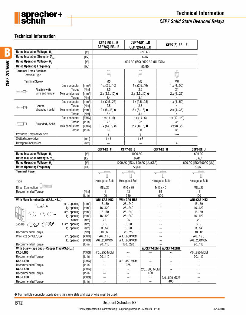
CEP7-ED1…B CEP7(S)-EE…B
CEP7-ED1…DCEP7(S)-EE…D
CEP7(S)-EE…E
Rated Insulation Voltage - UI [V] 690 AC Rated Insulation Strength- Uimp [kV] 6 ACRated Operation Voltage - Ue [V] 690 AC (IEC) / 600 AC (UL/CSA)Rated Operating Frequency [Hz] 50/60Terminal Cross Sections
Terminal Type
Terminal Screw M5 M5 M8
Flexible with wire end ferrule
One conductor [mm2] 1 x (2.5...16) 1 x (2.5...16) 1 x (4...50)Torque [Nm] 2.5 2.5 24
Two conductors [mm2] 2 x (2.5...10) ➊ 2 x (2.5...10) ➊ 2 x (4...25)Torque [Nm] 3.4 3.4 4
Course stranded / solid
One conductor [mm2] 1 x (2.5...25) 1 x (2.5...25) 1 x (4...50)Torque [Nm] 2.5 2.5 4
Two conductors [mm2] 2 x (6...16) ➊ 2 x (6...16) ➊ 2 x (4...35)Torque [Nm] 3.4 3.4 4
Stranded / Solid
One conductor [AWG] 1 x (14...6) 1 x (14...6) 1 x (12...1/0)Torque [lb-in] 22 22 35
Two conductors [AWG] 2 x (14...6) ➊ 2 x (14...6) ➊ 2 x (8...2)Torque [lb-in] 30 30 35
Pozidrive Screwdriver Size 2 2 ----Slotted screwdriver [mm] 1 x 6 1 x 6 ---Hexagon Socket Size [mm] --- --- 4
CEP7-EE_F CEP7-EE_G CEP7-EE_H CEP7-EE_JRated Insulation Voltage - UI [V] 1000 AC 690 ACRated Insulation Strength- Uimp [kV] 6 AC 6 ACRated Operation Voltage - Ue [V] 1000 AC (IEC) / 600 AC (UL/CSA) 690 AC (IEC)/600AC (UL)Rated Operating Frequency [Hz] 50/60 50/60Terminal Power
Type Hexagonal Bolt Hexagonal Bolt Hexagonal Bolt Hexagonal Bolt
Direct Connection M8 x 25 M10 x 30 M12 x 40 M8 x 25Recommended Torque [Nm] 11 43 68 11
[lb-in] 100 380 600 100With Main Terminal Set (CA6...HB...) With CA6-HB2 With CA6-HB3 With CA6-HB2
CA6-HB
sm. opening [mm2] 16...50 25...240 ~ 16...50lg. opening [mm2] 16...120 25...240 ~ 16...120
sm. opening [mm2] 16...50 25...240 ~ 16...50
lg. opening [mm2] 16...120 25...240 ~ 16...120
b max. [mm] 20 25 ~ 20s. sm. opening [mm] 3...9 6...20 ~ 3...9
lg. opening [mm] 3...14 6...20 ~ 3...14Recommended Torque [Nm] 10...12 20...25 ~ 10...12Wire size per UL/CSA sm. opening [AWG] #6...1 / 0 #4....600MCM ~ #6...1 / 0
lg. opening [AWG] #6...250MCM #4....600MCM ~ #6...250MCMRecommended Torque [lb-in] 90...110 180...220 ~ 90...110With Screw-type Lugs - Copper Clad (CA6-L...) W/CEP7-EEMH W/CEP7-EEHHCA6-L180 [AWG] #6...250 MCM ~ ~
~~~
#6...250 MCMRecommended Torque [lb-in] 90...110 ~ 90...110CA6-L420 [AWG] ~ #2...350 MCM ~
~~ ~
~Recommended Torque [lb-in] ~ 375 ~CA6-L630 [AWG] ~ ~ 2/0...500 MCM
400~ ~
~Recommended Torque [lb-in] ~ ~ ~CA6-L860 [AWG] ~ ~ ~
~2/0...500 MCM
400~
Recommended Torque [lb-in] ~ ~ ~
Technical Information
➊ For multiple conductor applications the same style and size of wire must be used.
Technical InformationCEP7 Solid State Overload Relays
B
CEP
7 Ov
erlo
ads
B13visit www.sprecherschuh.com/ecatalog for pricing and the most up to date informationSSNA2018
Discount Schedule B3www.sprecherschuh.com/ecatalog - All pricing shown in US dollars - FY20
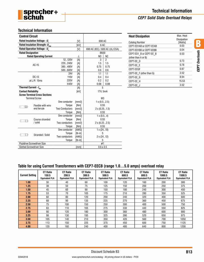
Control CircuitRated Insulation Voltage - UI [V] 690 ACRated Insulation Strength- Uimp [kV] 6 ACRated Operation Voltage - Ue [V] 690 AC (IEC) / 600 AC (UL/CSA)Rated Designation B600
Rated Operating Current Ie NO NC
AC-15
12...120V [A] 3 2220...240V [A] 1.5 1.5380...480V [A] 0.75 0.75500...600V [A] 0.6 0.6
DC-13at L/R 15ms
24V [A] 1.1 1.1110V [A] 0.4 0.4220V [A] 0.2 0.2440V [A] 0.08 0.08
Thermal Current - Ithe [A] 5Contact Reliability [kV] 17V, 5mAScrew Terminal Cross Sections
Terminal Screw M3
Flexible with wire end ferrule
One conductor [mm2] 1 x (0.5...2.5)Torque [Nm] 0.55
Two Conductors [mm2] 2 x (0.25...1.5)Torque [Nm] 0.55
Course stranded / solid
One conductor [mm2] 1 x (0.5...4)Torque [Nm] 0.55
Two conductors [mm2] 2 x (0.22...2.5)Torque [Nm] 0.55
Stranded / Solid
One conductor [AWG] 1 x (24...10)Torque [lb-in] 5
Two conductors [AWG] 2 x (24...12)Torque [lb-in] 5
Pozidrive Screwdriver Size #1Slotted Screwdriver Size [mm] 0.6 x 3.5
Technical InformationCEP7 Solid State Overload Relays
Technical Information
Current SettingCT Ratio
150:5Equivalent FLA
CT Ratio200:5
Equivalent FLA
CT Ratio300:5
Equivalent FLA
CT Ratio500:5
Equivalent FLA
CT Ratio600:5
Equivalent FLA
CT Ratio800:5
Equivalent FLA
CT Ratio1000:5
Equivalent FLA
CT Ratio1500:5
Equivalent FLA
1.001.251.501.752.002.252.502.753.003.253.503.754.00
30384553606875839098
105113120
405060708090
100110120130140150160
607590
105120135150165180195210225240
100125150175200225250275300325350375400
120150180210240270300330360390420450480
160200240280320360400440480520560600640
200250300350400450500550600650700750800
300375450525600675750825900975
105011251200
Table for using Current Transformers with CEP7-EECB (range 1.0…5.0 amps) overload relay
Heat Dissipation Max. Heat Dissipation
[Watts]Catalog NumberCEP7-ED1AB or CEP7-EEAB 0.03
CEP7-ED1BB or CEP7-EEBB 0.04
CEP7-ED1_B or CEP7-EE_B (other than A or B)
0.53
CEP7-EE_D 0.73
CEP7-EE_E 0.78
CEP7-EEGF 0.87
CEP7-EE_F (other than G) 3.52
CEP7-EE_G 8.94
CEP7-EE_H 15.53
CEP7-EE_J 3.52
B
CEP
7 Ov
erlo
ads
B14visit www.sprecherschuh.com/ecatalog for pricing and the most up to date information SSNA2018
Discount Schedule B3www.sprecherschuh.com/ecatalog - All pricing shown in US dollars - FY20
Technical InformationCEP7 Solid State Overload Relays
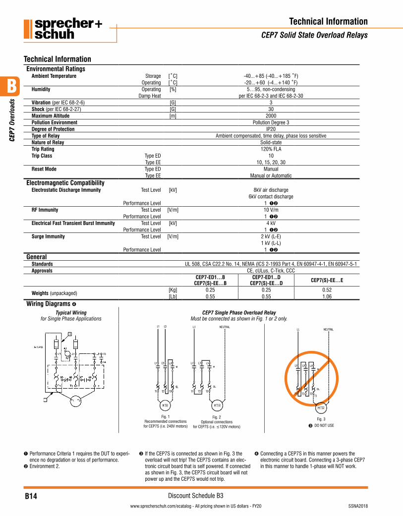
Technical InformationEnvironmental Ratings
Ambient Temperature Storage [˚C] -40...+85 (-40...+185 ˚F)Operating [˚C] -20...+60 (-4...+140 ˚F)
Humidity Operating [%] 5…95, non-condensingDamp Heat per IEC 68-2-3 and IEC 68-2-30
Vibration (per IEC 68-2-6) [G] 3Shock (per IEC 68-2-27) [G] 30Maximum Altitude [m] 2000Pollution Environment Pollution Degree 3Degree of Protection IP20Type of Relay Ambient compensated, time delay, phase loss sensitiveNature of Relay Solid-stateTrip Rating 120% FLATrip Class Type ED 10
Type EE 10, 15, 20, 30Reset Mode Type ED Manual
Type EE Manual or AutomaticElectromagnetic Compatibility
Electrostatic Discharge Immunity Test Level [kV] 8kV air discharge6kV contact discharge
Performance Level 1 ➊➋
RF Immunity Test Level [V/m] 10 V/mPerformance Level 1 ➊➋
Electrical Fast Transient Burst Immunity Test Level [kV] 4 kVPerformance Level 1 ➊➋
Surge Immunity Test Level [V/m] 2 kV (L-E)1 kV (L-L)
Performance Level 1 ➊➋
GeneralStandards UL 508, CSA C22.2 No. 14, NEMA (ICS 2-1993 Part 4, EN 60947-4-1, EN 60947-5-1Approvals CE, cULus, C-Tick, CCC
CEP7-ED1…BCEP7(S)-EE…B
CEP7-ED1...DCEP7(S)-EE…D CEP7(S)-EE…E
Weights (unpackaged)[Kg] 0.25 0.25 0.52[Lb] 0.55 0.55 1.06
Wiring Diagrams ➍Typical Wiring
for Single Phase ApplicationsCEP7 Single Phase Overload Relay
Must be connected as shown in Fig. 1 or 2 only.
Fig. 1Recommended connections
for CEP7S (i.e. 240V motors)
Fig. 2Optional connections
for CEP7S (i.e. ≤120V motors)
Fig. 3
➌ DO NOT USE
➊ Performance Criteria 1 requires the DUT to experi-ence no degradation or loss of performance.
➋ Environment 2.
➌ If the CEP7S is connected as shown in Fig. 3 the overload will not trip! The CEP7S contains an elec-tronic circuit board that is self powered. If connected as shown in Fig. 3, the CEP7S circuit board will not power up and the CEP7S would not trip.
➍ Connecting a CEP7S in this manner powers the electronic circuit board. Connecting a 3-phase CEP7 in this manner to handle 1-phase will NOT work.
B
CEP
7 Ov
erlo
ads
B15visit www.sprecherschuh.com/ecatalog for pricing and the most up to date informationSSNA2018
Discount Schedule B3www.sprecherschuh.com/ecatalog - All pricing shown in US dollars - FY20
Technical InformationCEP7 Solid State Overload Relays
Technical Information
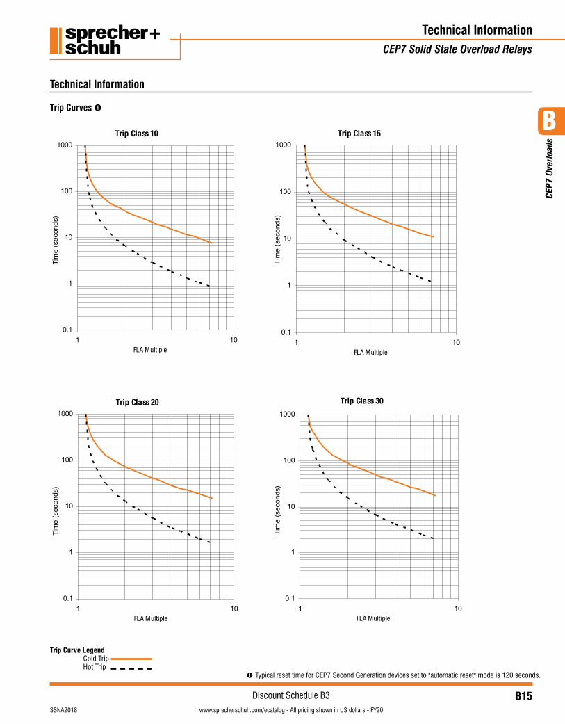
Trip Curve Legend Cold Trip Hot Trip
Trip Curves ➊
➊ Typical reset time for CEP7 Second Generation devices set to "automatic reset" mode is 120 seconds.
B
CEP
7 Ov
erlo
ads
B16visit www.sprecherschuh.com/ecatalog for pricing and the most up to date information SSNA2018
Discount Schedule B3www.sprecherschuh.com/ecatalog - All pricing shown in US dollars - FY20
Technical InformationCEP7 Solid State Overload Relays
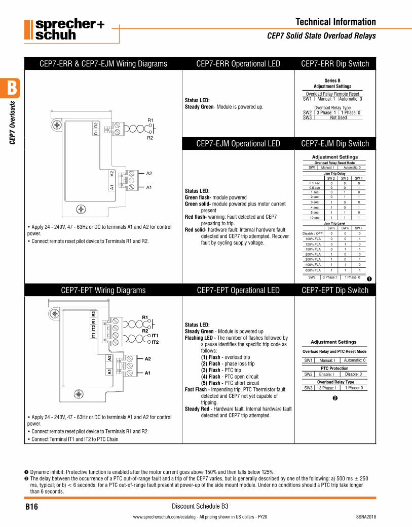
CEP7-ERR & CEP7-EJM Wiring Diagrams CEP7-ERR Operational LED CEP7-ERR Dip Switch
2R
1R
2A
1A A1
A2
R2
R1
• Apply 24 - 240V, 47 - 63Hz or DC to terminals A1 and A2 for control power.• Connect remote reset pilot device to Terminals R1 and R2.
Status LED: Steady Green- Module is powered up.
Series BAdjustment Settings
Overload Relay Remote ResetSW1 Manual: 1 Automatic: 0
Overload Relay TypeSW2 3 Phase: 1 1 Phase: 0SW3 Not Used
CEP7-EJM Operational LED CEP7-EJM Dip Switch
Status LED:Green flash- module poweredGreen solid- module powered plus motor current
presentRed flash- warning: Fault detected and CEP7
preparing to trip.Red solid- hardware fault: Internal hardware fault
detected and CEP7 trip attempted. Recover fault by cycling supply voltage.
Adjustment Settings
SW8 3 Phase: I 1 Phase: 0
SW1 Manual: I
SW 3SW 2
SW 5 SW 6 SW 7
SW 4
Overload Relay Reset Mode
Jam Trip Delay
Jam Trip Level
Automatic: 0
Disable / OFF100% FLA125% FLA150% FLA200% FLA300% FLA400% FLA600% FLA
0101010
1
0.1 sec0.5 sec1 sec2 sec3 sec4 sec5 sec10 sec
0000
1111
0011
0011
01010101
0000111
1
0011001
1
➊
CEP7-EPT Wiring Diagrams CEP7-EPT Operational LED CEP7-EPT Dip Switch
2R
1R
2TI
1TI
2A
1A A1
A2
R1
R2
IT2IT1
• Apply 24 - 240V, 47 - 63Hz or DC to terminals A1 and A2 for control power.• Connect remote reset pilot device to Terminals R1 and R2• Connect Terminal IT1 and IT2 to PTC Chain
Status LED: Steady Green - Module is powered up Flashing LED - The number of flashes followed by
a pause identifies the specific trip code as follows:
(1) Flash - overload trip (2) Flash - phase loss trip (3) Flash - PTC trip (4) Flash - PTC open circuit (5) Flash - PTC short circuitFast Flash - Impending trip. PTC Thermistor fault
detected and CEP7 not yet capable of tripping.
Steady Red - Hardware fault. Internal hardware fault detected and CEP7 trip attempted.
Adjustment Settings
SW1 Manual: I
SW2 Enable: I
Overload Relay and PTC Reset Mode
PTC ProtectionDisable: 0
Automatic: 0
SW3 3 Phase: IOverload Relay Type
1 Phase: 0
➋
➊ Dynamic inhibit: Protective function is enabled after the motor current goes above 150% and then falls below 125%. ➋ The delay between the occurrence of a PTC out-of-range fault and a trip of the CEP7 varies, but is generally described by one of the following: a) 500 ms ± 250
ms, typical; or b) < 6 seconds, for a PTC out-of-range fault present at power-up of the side mount module. Under no conditions should a PTC trip take longer than 6 seconds.
B
CEP
7 Ov
erlo
ads
B17visit www.sprecherschuh.com/ecatalog for pricing and the most up to date informationSSNA2018
Discount Schedule B3www.sprecherschuh.com/ecatalog - All pricing shown in US dollars - FY20
Technical InformationCEP7 Solid State Overload Relays
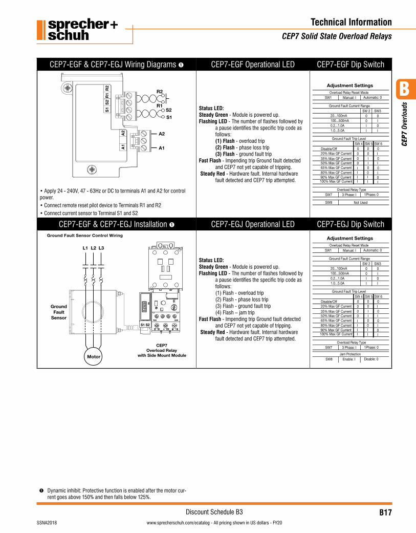
CEP7-EGF & CEP7-EGJ Wiring Diagrams ➊ CEP7-EGF Operational LED CEP7-EGF Dip Switch
2A
1A A1
A2
R1
R2
S1
S22
R1
R2
S1
S
• Apply 24 - 240V, 47 - 63Hz or DC to terminals A1 and A2 for control power.• Connect remote reset pilot device to Terminals R1 and R2• Connect current sensor to Terminal S1 and S2
Status LED: Steady Green - Module is powered up.Flashing LED - The number of flashes followed by
a pause identifies the specific trip code as follows:
(1) Flash - overload trip (2) Flash - phase loss trip (3) Flash - ground fault tripFast Flash - Impending trip Ground fault detected
and CEP7 not yet capable of tripping. Steady Red - Hardware fault. Internal hardware
fault detected and CEP7 trip attempted.
Adjustment Settings
SW1 Manual: I
SW 2 SW30 00 II 0I I
SW 4 SW 6SW 50 0
00
0 I00IIII
0
0
II I
I
III00
0
20...100mA100...500mA0.2...1.0A1.0...5.0A
Overload Relay Reset Mode
Ground Fault Current Range
Ground Fault Trip Level
Automatic: 0
SW7 3 Phase: I Overload Relay Type
1Phase: 0
SW8 Not Used
Disable/Off20% Max GF Current35% Max GF Current50% Max GF Current65% Max GF Current80% Max GF Current90% Max GF Current100% Max GF Current
CEP7-EGF & CEP7-EGJ Installation ➊ CEP7-EGJ Operational LED CEP7-EGJ Dip SwitchGround Fault Sensor Control Wiring
Motor
L2 L3L1
GroundFault
Sensor
CEP7Overload Relay
with Side Mount Module
S1 S2
Status LED: Steady Green - Module is powered up.Flashing LED - The number of flashes followed by
a pause identifies the specific trip code as follows:
(1) Flash - overload trip (2) Flash - phase loss trip (3) Flash - ground fault trip (4) Flash – jam tripFast Flash - Impending trip Ground fault detected
and CEP7 not yet capable of tripping. Steady Red - Hardware fault. Internal hardware
fault detected and CEP7 trip attempted.
SW8 Enable: I Jam Protection
Disable: 0
Adjustment Settings
SW1 Manual: I
SW 2 SW30 00 II 0I I
SW 4 SW 6SW 50 0
00
0 I00IIII
0
0
II I
I
III00
0
20...100mA100...500mA0.2...1.0A1.0...5.0A
Overload Relay Reset Mode
Ground Fault Current Range
Ground Fault Trip Level
Automatic: 0
SW7 3 Phase: I Overload Relay Type
1Phase: 0
Disable/Off20% Max GF Current35% Max GF Current50% Max GF Current65% Max GF Current80% Max GF Current90% Max GF Current100% Max GF Current
➊ Dynamic inhibit: Protective function is enabled after the motor cur-rent goes above 150% and then falls below 125%.
B
CEP
7 Ov
erlo
ads
B18visit www.sprecherschuh.com/ecatalog for pricing and the most up to date information SSNA2018
Discount Schedule B3www.sprecherschuh.com/ecatalog - All pricing shown in US dollars - FY20
Technical InformationCEP7 Network Communicating Module
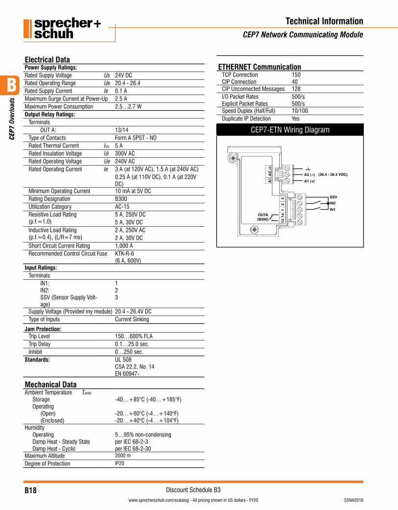
Electrical DataPower Supply Ratings:Rated Supply Voltage Us 24V DCRated Operating Range Ue 20.4 - 26.4Rated Supply Current Ie 0.1 AMaximum Surge Current at Power-Up 2.5 AMaximum Power Consumption 2.5…2.7 WOutput Relay Ratings:
TerminalsOUT A: 13/14
Type of Contacts Form A SPST - NORated Thermal Current Ithe 5 ARated Insulation Voltage Ui 300V ACRated Operating Voltage Ue 240V ACRated Operating Current Ie 3 A (at 120V AC), 1.5 A (at 240V AC)
0.25 A (at 110V DC), 0.1 A (at 220V DC)
Minimum Operating Current 10 mA at 5V DCRating Designation B300Utilization Category AC-15Resistive Load Rating(p.f.=1.0)
5 A, 250V DC5 A, 30V DC
Inductive Load Rating(p.f.=0.4), (L/R=7 ms)
2 A, 250V AC2 A, 30V DC
Short Circuit Current Rating 1,000 ARecommended Control Circuit Fuse KTK-R-6
(6 A, 600V)Input Ratings:
TerminalsIN1:IN2:SSV (Sensor Supply Volt-age)
123
Supply Voltage (Provided my module) 20.4 - 26.4V DCType of Inputs Current Sinking
Jam Protection:Trip Level 150…600% FLATrip Delay 0.1…25.0 sec.Inhibit 0…250 sec.
Standards: UL 508CSA 22.2, No. 14EN 60947-
Mechanical DataAmbient Temperature Tamb
StorageOperating
(Open)(Enclosed)
-40…+85°C (-40…+185°F)
-20…+60°C (-4…+140°F)-20…+40°C (-4…+104°F)
HumidityOperatingDamp Heat - Steady StateDamp Heat - Cyclic
5…95% non-condensingper IEC 68-2-3per IEC 68-2-30
Maximum Altitude 2000 m
Degree of Protection IP20
ETHERNET CommunicationTCP ConnectionCIP Connection
15040
CIP Unconnected Messages 128I/O Packet RatesExplicit Packet Rates
500/s500/s
Speed Duplex (Half/Full) 10/100Duplicate IP Detection Yes
CEP7-ETN Wiring Diagram
OUTA(B300) 13
141
23 SSV
IN2IN1
A1 (+)A2 (-) (20.4 - 26.4 VDC)
A1
A2
B
CEP
7 Ov
erlo
ads
B19visit www.sprecherschuh.com/ecatalog for pricing and the most up to date informationSSNA2018
Discount Schedule B3www.sprecherschuh.com/ecatalog - All pricing shown in US dollars - FY20
Technical Information/DimensionsCEP7 Solid State Overload Relays
CEP7-CBCT Installation
6X
6X
ØX
6X
Ø X
Single Cable per Phase
A
B C
CEP7-CBCT DimensionsCEP7-CBCT1
11.8(.47)
3.2(.13)
45.3(1.78)
23.1(.91)
¯ 19.1(¯ .75)
¯ 44.5(¯ 1.75)
D
63.5(2.50)
50.8(2.00)
3.2(.12)
4(.16)
5.3(.21)
12.7(.50)
E
F B
A
C
96(3.78)
CAT
CEP7-CBCT2
A
89.6(3.53)
B
48.3(1.90)
CDimensions
39.6(1.56)
¿ D
54.6(2.15)
E
69.9(2.75)
122.4(4.82)CEP7-CBCT3 115.9
(4.56)59.7
(2.35)63.5
(2.50)54.1
(2.13)96
(3.78)
F
44.5(1.75)
56.2(2.21)
74.4(2.93)
123.2(4.85)
96.7(3.81)
CEP7-CBCT2CEP7-CBCT3
CEP7-CBCT4
CEP7-CBCT1
11.8(.47)
146.8(5.78)
143.5(5.65)
5.5(.22)
74.9(2.95) 3.2
(.13)
82.6(3.25)
CEP7-CBCT4
11.8(.47)
3.2(.13)
45.3(1.78)
23.1(.91)
¯ 19.1(¯ .75)
¯ 44.5(¯ 1.75)
D
63.5(2.50)
50.8(2.00)
3.2(.12)
4(.16)
5.3(.21)
12.7(.50)
E
F B
A
C
96(3.78)
CAT
CEP7-CBCT2
A
89.6(3.53)
B
48.3(1.90)
CDimensions
39.6(1.56)
¿ D
54.6(2.15)
E
69.9(2.75)
122.4(4.82)CEP7-CBCT3 115.9
(4.56)59.7
(2.35)63.5
(2.50)54.1
(2.13)96
(3.78)
F
44.5(1.75)
56.2(2.21)
74.4(2.93)
123.2(4.85)
96.7(3.81)
CEP7-CBCT2CEP7-CBCT3
CEP7-CBCT4
CEP7-CBCT1
11.8(.47)
146.8(5.78)
143.5(5.65)
5.5(.22)
74.9(2.95) 3.2
(.13)
82.6(3.25)
CEP7-CBCT2 & 3
11.8(.47)
3.2(.13)
45.3(1.78)
23.1(.91)
¯ 19.1(¯ .75)
¯ 44.5(¯ 1.75)
D
63.5(2.50)
50.8(2.00)
3.2(.12)
4(.16)
5.3(.21)
12.7(.50)
E
F B
A
C
96(3.78)
CAT
CEP7-CBCT2
A
89.6(3.53)
B
48.3(1.90)
CDimensions
39.6(1.56)
¿ D
54.6(2.15)
E
69.9(2.75)
122.4(4.82)CEP7-CBCT3 115.9
(4.56)59.7
(2.35)63.5
(2.50)54.1
(2.13)96
(3.78)
F
44.5(1.75)
56.2(2.21)
74.4(2.93)
123.2(4.85)
96.7(3.81)
CEP7-CBCT2CEP7-CBCT3
CEP7-CBCT4
CEP7-CBCT1
11.8(.47)
146.8(5.78)
143.5(5.65)
5.5(.22)
74.9(2.95) 3.2
(.13)
82.6(3.25)
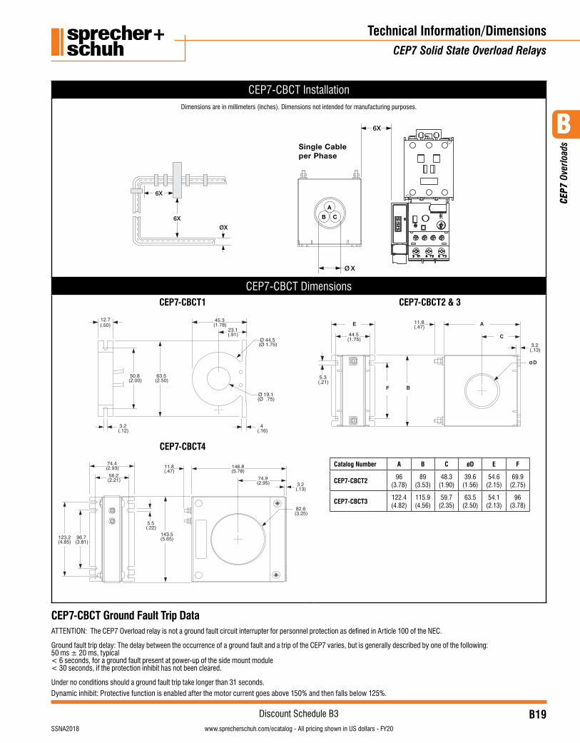
Catalog Number A B C øD E F
CEP7-CBCT2 96(3.78)
89(3.53)
48.3(1.90)
39.6(1.56)
54.6(2.15)
69.9(2.75)
CEP7-CBCT3 122.4(4.82)
115.9(4.56)
59.7(2.35)
63.5(2.50)
54.1(2.13)
96(3.78)
CEP7-CBCT Ground Fault Trip Data ATTENTION: The CEP7 Overload relay is not a ground fault circuit interrupter for personnel protection as defined in Article 100 of the NEC.
Ground fault trip delay: The delay between the occurrence of a ground fault and a trip of the CEP7 varies, but is generally described by one of the following: 50 ms ± 20 ms, typical < 6 seconds, for a ground fault present at power-up of the side mount module < 30 seconds, if the protection inhibit has not been cleared.
Under no conditions should a ground fault trip take longer than 31 seconds.Dynamic inhibit: Protective function is enabled after the motor current goes above 150% and then falls below 125%.
Dimensions are in millimeters (inches). Dimensions not intended for manufacturing purposes.
B
CEP
7 Ov
erlo
ads
B20visit www.sprecherschuh.com/ecatalog for pricing and the most up to date information SSNA2018
Discount Schedule B3www.sprecherschuh.com/ecatalog - All pricing shown in US dollars - FY20
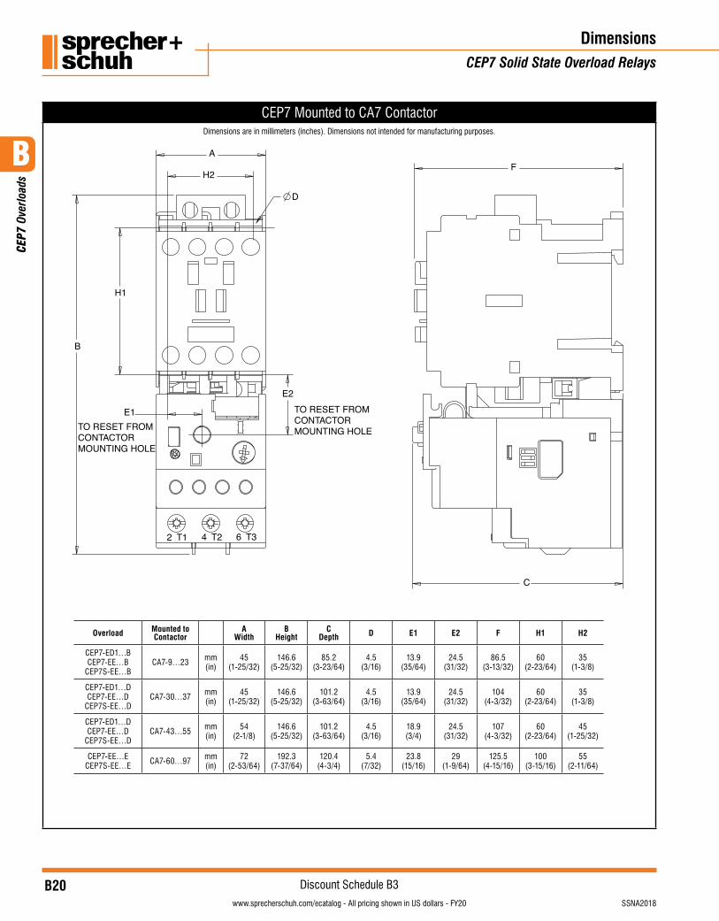
CEP7 Mounted to CA7 Contactor
Overload Mounted to Contactor
AWidth
BHeight
CDepth D E1 E2 F H1 H2
CEP7-ED1…BCEP7-EE…B
CEP7S-EE…BCA7-9…23 mm
(in)45
(1-25/32)146.6
(5-25/32)85.2
(3-23/64)4.5
(3/16)13.9
(35/64)24.5
(31/32)86.5
(3-13/32)60
(2-23/64)35
(1-3/8)
CEP7-ED1…DCEP7-EE…D
CEP7S-EE…DCA7-30…37 mm
(in)45
(1-25/32)146.6
(5-25/32)101.2
(3-63/64)4.5
(3/16)13.9
(35/64)24.5
(31/32)104
(4-3/32)60
(2-23/64)35
(1-3/8)
CEP7-ED1…DCEP7-EE…D
CEP7S-EE…DCA7-43…55 mm
(in)54
(2-1/8)146.6
(5-25/32)101.2
(3-63/64)4.5
(3/16)18.9(3/4)
24.5(31/32)
107(4-3/32)
60(2-23/64)
45(1-25/32)
CEP7-EE…ECEP7S-EE…E CA7-60…97 mm
(in)72
(2-53/64)192.3
(7-37/64)120.4
(4-3/4)5.4
(7/32)23.8
(15/16)29
(1-9/64)125.5
(4-15/16)100
(3-15/16)55
(2-11/64)
DimensionsCEP7 Solid State Overload Relays
Dimensions are in millimeters (inches). Dimensions not intended for manufacturing purposes.
B
CEP
7 Ov
erlo
ads
B21visit www.sprecherschuh.com/ecatalog for pricing and the most up to date informationSSNA2018
Discount Schedule B3www.sprecherschuh.com/ecatalog - All pricing shown in US dollars - FY20
Dimensions/TechnicalCEP7 Solid State Overload Relays
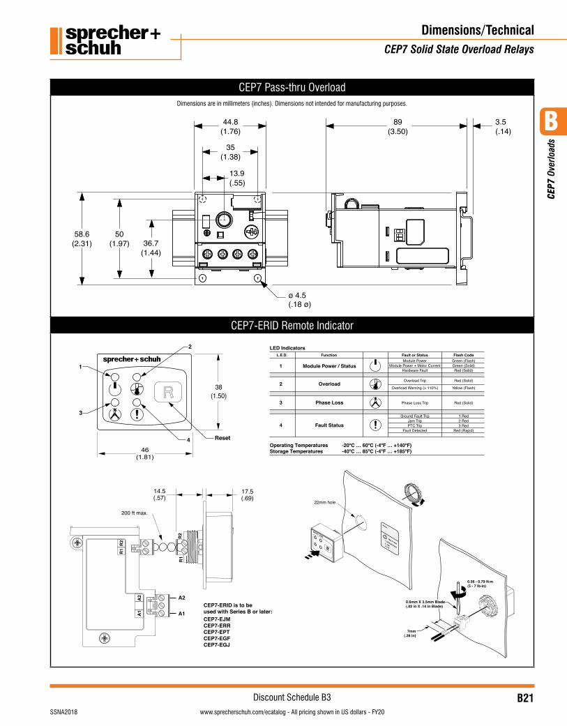
CEP7 Pass-thru Overload
44.8
35
13.9
(.18 ø)ø 4.5
3.589
(2.31)58.6
(1.97)50
(1.44)36.7
(1.76)
(1.38)
(.55)
(.14)(3.50)
CEP7-ERID Remote Indicator
R1
R2
R1
R2
A1
A2
A1
A2CEP7-ERID is to be used with Series B or later:CEP7-EJMCEP7-ERRCEP7-EPTCEP7-EGFCEP7-EGJ
0.56 - 0.79 N.m(5 - 7 lb-in)
7mm(.28 in)
0.6mm X 3.5mm Blade(.02 in X .14 in Blade)
Function edoC hsalFsutatS ro tluaF.D.E.LModule Power Green (Flash)
Overload Trip Red (Solid)
Overload Warning (> 110%) Yellow (Flash)
Phase Loss Trip Red (Solid)
Module Power + Motor Current Green (Solid)Hardware Fault Red (Solid)
Ground Fault Trip 1 RedJam Trip 2 RedPTC Trip 3 Red
Fault Detected Red (Rapid)
11
2
Reset4
3
Module Power / Status
2 Overload
3 Phase Loss
4 Fault Status
FAULT CODE
Starter:
1- GROUND FAULT
2- JAM 3- PTC
(1.81)46
(.69)17.5
(.57)14.5
(1.50)38
200 ft max.
22mm hole
LED Indicators
Operating Temperatures -20¼C É 60¼C (-4¼F É +140¼F)Storage Temperatures -40¼C É 85¼C (-4¼F É +185¼F)
Dimensions are in millimeters (inches). Dimensions not intended for manufacturing purposes.
B
CEP
7 Ov
erlo
ads
B22visit www.sprecherschuh.com/ecatalog for pricing and the most up to date information SSNA2018
Discount Schedule B3www.sprecherschuh.com/ecatalog - All pricing shown in US dollars - FY20
DimensionsCEP7 Solid State Overload Relays
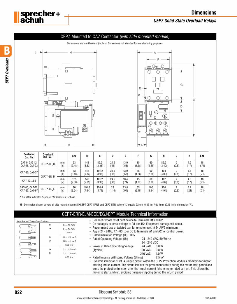
CEP7 Mounted to CA7 Contactor (with side mounted module)
A
F
G
B
D
E
K
L
H
C
J
Contactor Cat. No.
Overload Cat. No. A ➊ B C D E F G H J K L ➊
CA7-9, CA7-12, CA7-16, CA7-23 CEP7*-EE_B mm
(in)63
(2.48)148
(5.83)85.2
(3.35)24.5(.96)
13.9(.55)
35(1.38)
60(2.38)
86.5(3.40)
2(0.8)
4.5 (.17)
18 (.71)
CA7-30, CA7-37
CEP7*-EE_D
mm (in)
63 (2.48)
148(5.83)
101.2(3.98)
24.5(.96)
13.9(.55)
35(1.38)
60(2.38)
104(4.09)
2(0.8)
4.5 (.17)
18 (.71)
CA7-43…55 mm (in)
67.5 (2.66)
148(5.83)
101.2(3.98)
24.5(.96)
18.4(.74)
45(1.77)
60(2.38)
107(4.09)
2(0.8)
4.5 (.17)
18 (.71)
CA7-60, CA7-72, CA7-85, CA7-97 CEP7*-EE_E mm
(in)90
(3.54)191.6(7.54)
120.4(4.74)
29(1.14)
23.8(.94)
55(2.16)
100(3.94)
126(4.94)
2(0.8)
5.4 (.21)
18 (.71)
* No letter indicates 3-phase; "S" indicates 1-phase
➊ Dimension shown covers all side mount modules EXCEPT CEP7-EPRB and CEP7-ETN, where “L” equals 22mm (0.86 in). Add 4mm (0.16 in) to dimension “A”.
CEP7-ERR/EJM/EGE/EGJ/EPT Module Technical InformationWire Size and Torque Specifications
1X
2X
24.....12 AWG
24.....16 AWG
5 lb-in
1X
2X
0.2......2.5 mm2
0.25.......1 mm2
0.55 N.m
1X
2X
0.2.....2.5 mm2
0.2........1 mm2
0.55 N.m
• Connect remote reset pilot device to Terminals R1 and R2.• Do not apply external voltage to R1 and R2. Equipment damage will occur.• Recommend use of twisted pair for remote reset, #24 AWG minimum.• Apply 24 - 240V, 47 - 63Hz or DC to terminals A1 and A2 for control power.• Rated Insulation Voltage (Ui) 300V• Rated Operating Voltage (Ue) 24 - 240 VAC, 50/60 Hz
24 - 240 VDC• Power at Rated Operating Voltage 24 VAC 0.8 W
(Typical) 120 VAC 0.8 W 240 VAC 1.0 W
• Rated Impulse Withstand Voltage (U imp) 2.5 kV• Dynamic inhibit on start. A unique circuit within the CEP7 Protection Modules monitors for motor
starting inrush current. The circuit inhibits the protection feature during the motor start period and arms the protection function after the inrush current falls to motor rated current. This allows the motor to start and run, avoiding nuisance tripping during the inrush period.
Dimensions are in millimeters (inches). Dimensions not intended for manufacturing purposes.
B
CEP
7 Ov
erlo
ads
B23visit www.sprecherschuh.com/ecatalog for pricing and the most up to date informationSSNA2018
Discount Schedule B3www.sprecherschuh.com/ecatalog - All pricing shown in US dollars - FY20
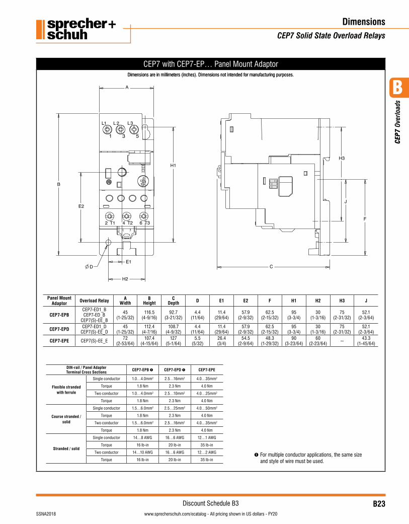
CEP7 with CEP7-EP… Panel Mount Adaptor
DimensionsCEP7 Solid State Overload Relays
Dimensions are in millimeters (inches). Dimensions not intended for manufacturing purposes.
Panel Mount Adaptor Overload Relay A
WidthB
HeightC
Depth D E1 E2 F H1 H2 H3 J
CEP7-EPBCEP7-ED1_BCEP7-ED_B
CEP7(S)-EE_B
45(1-25/32)
116.5(4-9/16)
92.7(3-21/32)
4.4(11/64)
11.4(29/64)
57.9(2-9/32)
62.5(2-15/32)
95(3-3/4)
30(1-3/16)
75(2-31/32)
52.1(2-3/64)
CEP7-EPD CEP7-ED1_DCEP7(S)-EE_D
45(1-25/32)
112.4(4-7/16)
108.7(4-9/32)
4.4(11/64)
11.4(29/64)
57.9(2-9/32)
62.5(2-15/32)
95(3-3/4)
30(1-3/16)
75(2-31/32)
52.1(2-3/64)
CEP7-EPE CEP7(S)-EE_E 72(2-53/64)
107.4(4-15/64)
127(5-1/64)
5.5(5/32)
26.4(3/4)
54.5(2-9/64)
48.3(1-29/32)
90(3-23/64)
60(2-23/64) ~ 43.3
(1-45/64)
DIN-rail / Panel Adapter Terminal Cross Sections CEP7-EPB ➊ CEP7-EPD ➊ CEP7-EPE
Flexible stranded with ferrule
Single conductor 1.0…4.0mm2 2.5…16mm2 4.0…35mm2
Torque 1.8 Nm 2.3 Nm 4.0 Nm
Two conductor 1.0…4.0mm2 2.5…10mm2 4.0…25mm2
Torque 1.8 Nm 2.3 Nm 4.0 Nm
Course stranded / solid
Single conductor 1.5…6.0mm2 2.5…25mm2 4.0…50mm2
Torque 1.8 Nm 2.3 Nm 4.0 Nm
Two conductor 1.5…6.0mm2 2.5…16mm2 4.0…35mm2
Torque 1.8 Nm 2.3 Nm 4.0 Nm
Stranded / solid
Single conductor 14…8 AWG 16…6 AWG 12…1 AWG
Torque 16 lb-in 20 lb-in 35 lb-in
Two conductor 14…10 AWG 16…6 AWG 12…2 AWG
Torque 16 lb-in 20 lb-in 35 lb-in➊ For multiple conductor applications, the same size
and style of wire must be used.
Dimensions are in millimeters (inches). Dimensions not intended for manufacturing purposes.
B
CEP
7 Ov
erlo
ads
B24visit www.sprecherschuh.com/ecatalog for pricing and the most up to date information SSNA2018
Discount Schedule B3www.sprecherschuh.com/ecatalog - All pricing shown in US dollars - FY20
F
I
J
BC
D
A
E
G
H
KL
B
I
A
K
45(1.77)
53(2.087)
G
LF
C
D
EH
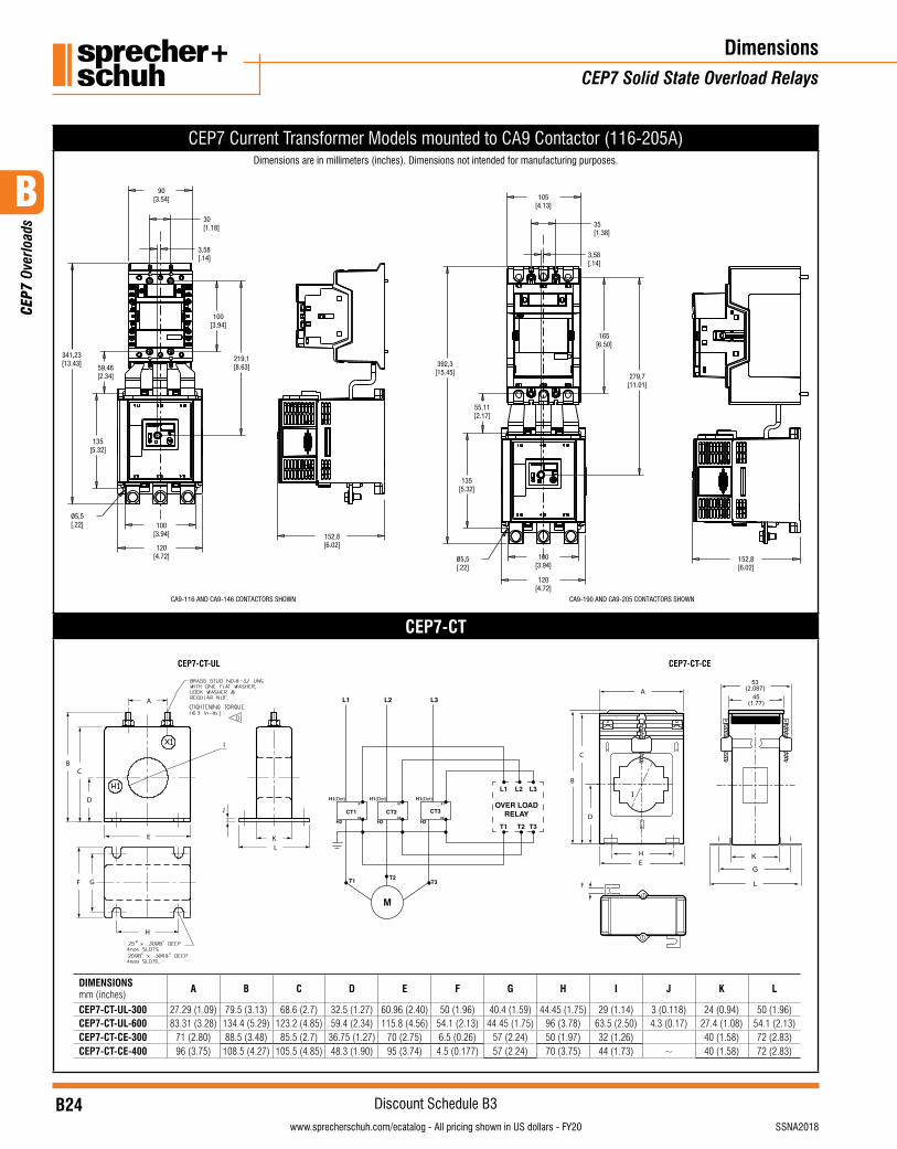
CEP7 Current Transformer Models mounted to CA9 Contactor (116-205A)Dimensions are in millimeters (inches). Dimensions not intended for manufacturing purposes.
30[1.18]
100[3.94]
135[5.32]
100[3.94]
90[3.54]
120[4.72]
341,23[13.43]
219,1[8.63]
3,58[.14]
Ø5,5[.22]
35[1.38]
165[6.50]
279,7[11.01]
3,58[.14]
100[3.94]
135[5.32]
59,46[2.34]
55,11[2.17]
120[4.72]
[.22]
105[4.13]
392,3[15.45]
152,8[6.02]
152,8[6.02]
CA9-116 AND CA9-146 CONTACTORS SHOWN CA9-190 AND CA9-205 CONTACTORS SHOWN
Ø5,5
CEP7-CT
DimensionsCEP7 Solid State Overload Relays
M
OVER LOADRELAY
L1
L1
T1 T2 T3
L2 L3
L2 L3
H1(Dot) H1(Dot) H1(Dot)
H2 H2 H2
X1 1X1X
X2X2X2CT1
T1 T2T3
CT2 CT3
DIMENSIONS mm (inches) A B C D E F G H I J K L
CEP7-CT-UL-300 27.29 (1.09) 79.5 (3.13) 68.6 (2.7) 32.5 (1.27) 60.96 (2.40) 50 (1.96) 40.4 (1.59) 44.45 (1.75) 29 (1.14) 3 (0.118) 24 (0.94) 50 (1.96)CEP7-CT-UL-600 83.31 (3.28) 134.4 (5.29) 123.2 (4.85) 59.4 (2.34) 115.8 (4.56) 54.1 (2.13) 44.45 (1.75) 96 (3.78) 63.5 (2.50) 4.3 (0.17) 27.4 (1.08) 54.1 (2.13)CEP7-CT-CE-300 71 (2.80) 88.5 (3.48) 85.5 (2.7) 36.75 (1.27) 70 (2.75) 6.5 (0.26) 57 (2.24) 50 (1.97) 32 (1.26) 40 (1.58) 72 (2.83)CEP7-CT-CE-400 96 (3.75) 108.5 (4.27) 105.5 (4.85) 48.3 (1.90) 95 (3.74) 4.5 (0.177) 57 (2.24) 70 (3.75) 44 (1.73) ~ 40 (1.58) 72 (2.83)
CEP7-CT-CECEP7-CT-UL
B
CEP
7 Ov
erlo
ads
B25visit www.sprecherschuh.com/ecatalog for pricing and the most up to date informationSSNA2018
Discount Schedule B3www.sprecherschuh.com/ecatalog - All pricing shown in US dollars - FY20
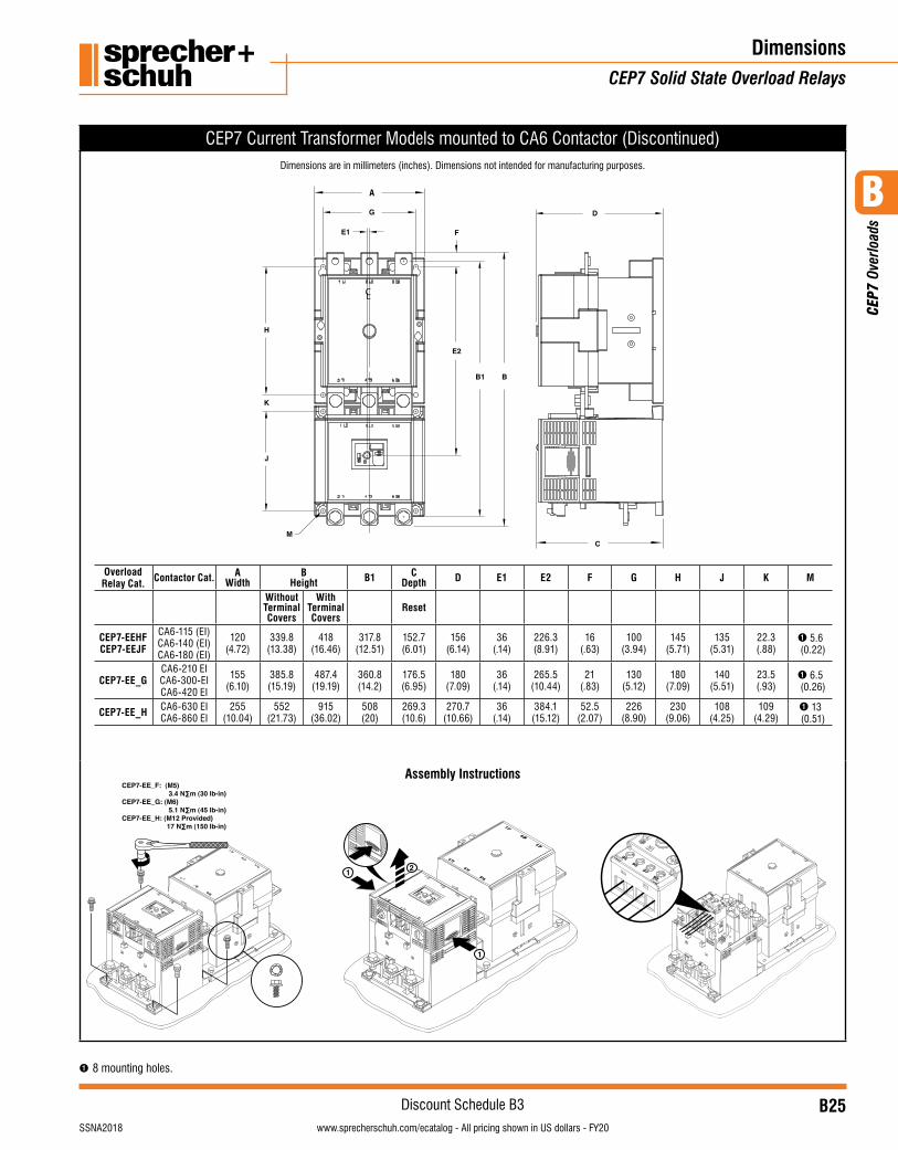
CEP7 Current Transformer Models mounted to CA6 Contactor (Discontinued)
A
Overload Relay Cat. Contactor Cat. A
WidthB
Height B1 CDepth D E1 E2 F G H J K M
Without Terminal Covers
With Terminal Covers
Reset
CEP7-EEHFCEP7-EEJF
CA6-115 (EI)CA6-140 (EI) CA6-180 (EI)
120(4.72)
339.8(13.38)
418(16.46)
317.8(12.51)
152.7 (6.01)
156(6.14)
36(.14)
226.3(8.91)
16(.63)
100(3.94)
145(5.71)
135(5.31)
22.3(.88)
➊ 5.6 (0.22)
CEP7-EE_G CA6-210 EICA6-300-EI CA6-420 EI
155(6.10)
385.8(15.19)
487.4(19.19)
360.8(14.2)
176.5(6.95)
180(7.09)
36(.14)
265.5(10.44)
21(.83)
130(5.12)
180(7.09)
140 (5.51)
23.5(.93)
➊ 6.5 (0.26)
CEP7-EE_H CA6-630 EI CA6-860 EI
255(10.04)
552(21.73)
915(36.02)
508(20)
269.3(10.6)
270.7(10.66)
36(.14)
384.1(15.12)
52.5(2.07)
226(8.90)
230(9.06)
108 (4.25)
109(4.29)
➊ 13 (0.51)
Assembly Instructions CEP7-EE_F: (M5) 3.4 N∑m (30 lb-in)CEP7-EE_G: (M6) 5.1 N∑m (45 lb-in)CEP7-EE_H: (M12 Provided) 17 N∑m (150 lb-in)
95 96
97 98
1
1
2
Dimensions are in millimeters (inches). Dimensions not intended for manufacturing purposes.
DimensionsCEP7 Solid State Overload Relays
➊ 8 mounting holes.

B
CEP
7 Ov
erlo
ads
B26visit www.sprecherschuh.com/ecatalog for pricing and the most up to date information SSNA2018
Discount Schedule B3www.sprecherschuh.com/ecatalog - All pricing shown in US dollars - FY20
DimensionsCEP7 Solid State Overload Relays
Notes