Embed Size (px)
Citation preview
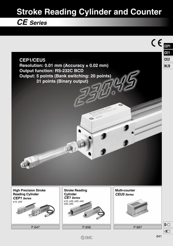
CEP1/CEU5Resolution: 0.01 mm (Accuracy ± 0.02 mm)Output function: RS-232C BCDOutput: 5 points (Bank switching: 20 points) 31 points (Binary output)
CE Series
Stroke Reading Cylinder and Counter
P.647 P.656 P.667
High Precision Stroke Reading CylinderCEP1 Seriesø12, ø20
Stroke Reading CylinderCE1 Seriesø12, ø20, ø32, ø40ø50, ø63
Multi-counterCEU5 Series
641
CEP1
CE1
CE2
ML2B
D-
-X
CE1
CEP1

Can be used in an environment where the product is exposed to fluids (water, oil,coolant, etc.)
System Configuration
High Precision Stroke Reading Cylinder (CEP1)
Stroke Reading Cylinder (CE1)
CEP1 Series CE1 Series
With special scraper as standardSpecial order (with scraper)
∗ The standard type of the CE1 series does not come with a scraper. Contact SMC since cylinders with a scraper are special orders.
Measurement is possible throughout the full stroke range.
When the counter is reset by pressing the cylinder rod to the reference plane, that point becomes the home position.
The home position can be anywherewithin the cylinder stroke.
• Resolution: 0.01 mm (Accuracy ±0.02 mm)• Special scraper now standard (IP-67)• 2 types of seal material available (Made to Order)• Power supply voltage 12 to 24 VDC
• Auto switch mounting orientation can be freely selected (3 mounting surfaces)
• Power supply voltage 12 to 24 VDC• Abundant stroke variations• Improved noise resistance
Extension cable CE1-R series
Stroke reading cylinderCE1 seriesCEP1 series
CounterCEU5
∗
• Resolution: 0.1 mm (Accuracy ±0.2 mm)
When used in an environment where the product is exposed to fluids (water, oil, coolant, etc.), the reading cylinder with a scraper is available as a special order. Contact SMC for details. (Except ø12, ø20)
Air Cylinder with Measurement Function/Stroke Reading Cylinder CE Series
Counter CEU Series
642
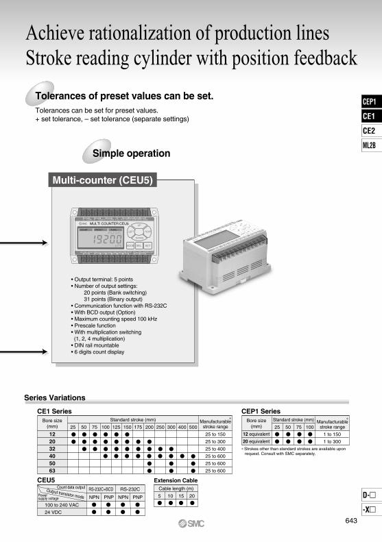
Achieve rationalization of production linesStroke reading cylinder with position feedback
Simple operation
Series Variations
CE1 Series
25 50 75 100 125 150 175 200 300 500
25 to 150
25 to 300
25 to 400
25 to 600
25 to 600
25 to 600
250 400
1 to 150
1 to 300
Standard stroke (mm)
CEP1 Series
12 equivalent
20 equivalent
25 50 75 100
Standard stroke (mm)
CEU5
100 to 240 VAC
24 VDC
NPN PNP NPN PNP
RS-232CRS-232C+BCD
Extension Cable
5 10 15 20
∗Strokes other than standard strokes are available upon request. Consult with SMC separately.
Tolerances of preset values can be set. Tolerances can be set for preset values.+ set tolerance, – set tolerance (separate settings)
122032405063
Bore size(mm)
Power supply voltage
Output transistor mode
Count data output
Manufacturablestroke range
Manufacturablestroke range
Bore size(mm)
Cable length (m)
∗ ∗
MULTI COUNTER:CEU5 A COM COM COMB DC12V GND F.G. R.S. HOLD BANK1 BANK2
COM S.STOPOUT1OUT2OUT3OUT4OUT5AC100~240V
COUNT PRESET FUNC.
SD SGRD RS-232C
UP
LEFT RIGHT
DOWN
SEL. SETMODE
• Output terminal: 5 points• Number of output settings:
20 points (Bank switching)31 points (Binary output)
• Communication function with RS-232C• With BCD output (Option)• Maximum counting speed 100 kHz• Prescale function• With multiplication switching (1, 2, 4 multiplication)
• DIN rail mountable• 6 digits count display
Multi-counter (CEU5)
643
CEP1
CE1
CE2
ML2B
D-
-X
CE1
CEP1
Application Examples
Detection of die assembly’sdeceleration point
Length/breadth discrimination
Inspection of machined holes
Measurement of dimensions Measurement of machining dimensions
Nozzle height adjustment
Detection of lifter position
Discrimination of direction
Confirmation of press-inParts inspection
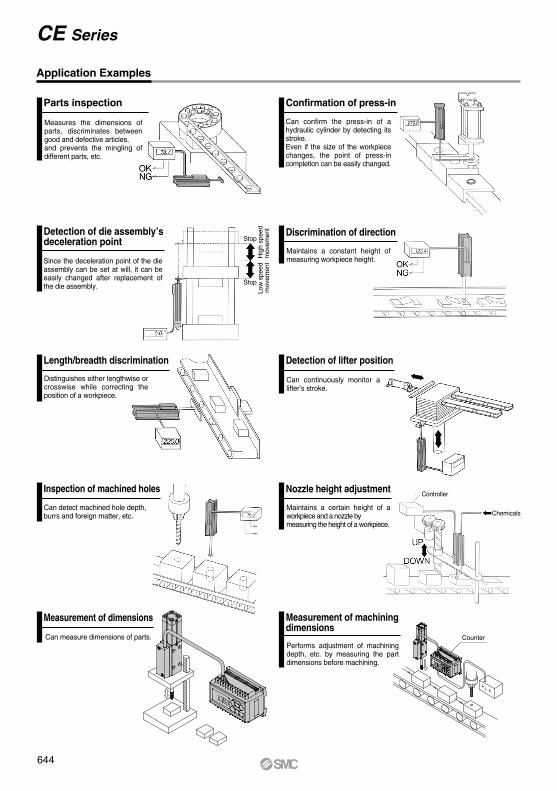
Measures the dimensions of parts, discriminates between good and defective articles, and prevents the mingling of different parts, etc.
Can confirm the press-in of a hydraulic cylinder by detecting its stroke.Even if the size of the workpiece changes, the point of press-in completion can be easily changed.
Since the deceleration point of the die assembly can be set at will, it can be easily changed after replacement of the die assembly.
Maintains a constant height of measuring workpiece height.
Can detect machined hole depth, burrs and foreign matter, etc.
Maintains a certain height of a workpiece and a nozzle by measuring the height of a workpiece.
Can continuously monitor a lifter’s stroke.
Performs adjustment of machining depth, etc. by measuring the part dimensions before machining.
CounterCan measure dimensions of parts.
Distinguishes either lengthwise or crosswise while correcting the position of a workpiece.
Controller
Chemicals
Controller
Stop
Hig
h sp
eed
mov
emen
tLo
w s
peed
mov
emen
t
Stop
644
CE Series
Measurement Principle A/B Phase Difference Output (90° phase difference output)
4 Times Multiplication Function
1 2 3
1 2 3 4 5 6 7 8 9
Counting Speed (kHz, kcps)
Accuracy
0.20.1 0.3
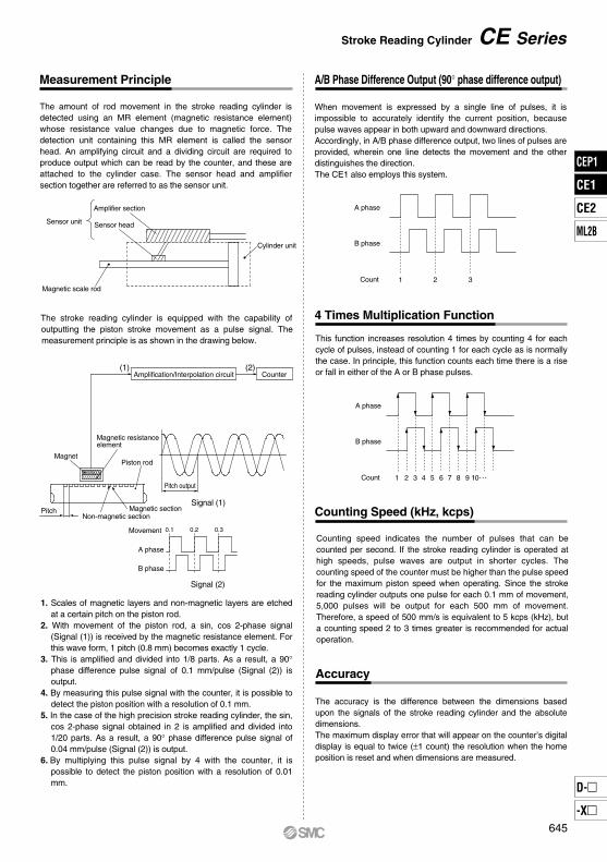
The amount of rod movement in the stroke reading cylinder is detected using an MR element (magnetic resistance element) whose resistance value changes due to magnetic force. The detection unit containing this MR element is called the sensor head. An amplifying circuit and a dividing circuit are required to produce output which can be read by the counter, and these are attached to the cylinder case. The sensor head and amplifier section together are referred to as the sensor unit.
The stroke reading cylinder is equipped with the capability of outputting the piston stroke movement as a pulse signal. The measurement principle is as shown in the drawing below.
1. Scales of magnetic layers and non-magnetic layers are etched at a certain pitch on the piston rod.
2. With movement of the piston rod, a sin, cos 2-phase signal (Signal (1)) is received by the magnetic resistance element. For this wave form, 1 pitch (0.8 mm) becomes exactly 1 cycle.
3. This is amplified and divided into 1/8 parts. As a result, a 90° phase difference pulse signal of 0.1 mm/pulse (Signal (2)) is output.
4. By measuring this pulse signal with the counter, it is possible to detect the piston position with a resolution of 0.1 mm.
5. In the case of the high precision stroke reading cylinder, the sin, cos 2-phase signal obtained in 2 is amplified and divided into 1/20 parts. As a result, a 90° phase difference pulse signal of 0.04 mm/pulse (Signal (2)) is output.
6. By multiplying this pulse signal by 4 with the counter, it is possible to detect the piston position with a resolution of 0.01 mm.
Signal (2)
A phase
Movement
B phase
Signal (1)
Pitch output
Piston rodMagnet
Non-magnetic section
Magnetic resistanceelement
Magnetic sectionPitch
(1) (2)Amplification/Interpolation circuit Counter
Sensor unit
Amplifier section
Sensor head
Magnetic scale rod
Cylinder unit
A phase
B phase
Count
A phase
B phase
Count
When movement is expressed by a single line of pulses, it is impossible to accurately identify the current position, because pulse waves appear in both upward and downward directions.Accordingly, in A/B phase difference output, two lines of pulses are provided, wherein one line detects the movement and the other distinguishes the direction.The CE1 also employs this system.
This function increases resolution 4 times by counting 4 for each cycle of pulses, instead of counting 1 for each cycle as is normally the case. In principle, this function counts each time there is a rise or fall in either of the A or B phase pulses.
Counting speed indicates the number of pulses that can be counted per second. If the stroke reading cylinder is operated at high speeds, pulse waves are output in shorter cycles. The counting speed of the counter must be higher than the pulse speed for the maximum piston speed when operating. Since the stroke reading cylinder outputs one pulse for each 0.1 mm of movement, 5,000 pulses will be output for each 500 mm of movement. Therefore, a speed of 500 mm/s is equivalent to 5 kcps (kHz), but a counting speed 2 to 3 times greater is recommended for actual operation.
The accuracy is the difference between the dimensions based upon the signals of the stroke reading cylinder and the absolute dimensions.The maximum display error that will appear on the counter’s digital display is equal to twice (±1 count) the resolution when the home position is reset and when dimensions are measured.
645
Stroke Reading Cylinder CE Series
CEP1
CE1
CE2
ML2B
D-
-X
CE1
CEP1
Mounting
Noise Counter Measures
CautionCaution
Sensor Unit
Handling of Technical Material
Effects of Noise
23 m∗
ø12
ø20 to ø32
ø40 to ø63
Bore size Allowablerotational torque
10 N·m
20 N·m
30 N·m
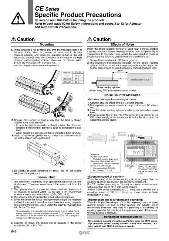
1. When screwing a nut or fitting, etc. onto the threaded section at the end of the piston rod, return the piston rod to its fully retracted position, and grasp the exposed portion of the rod across two parallel sides with a wrench. In the case of the high precision stroke reading cylinder, there are no parallel sides. Secure the workpiece with a double nut. Note) Do not apply rotational torque to the piston rod.
2. Operate the cylinder in such a way that the load is always applied in the axial direction.• In case the load is applied in a direction other than the axial
direction of the cylinder, provide a guide to constrain the load itself.
• When mounting a cylinder, centering should be done carefully.3. Avoid using the air cylinder in such a way that rotational torque
would be applied to the piston rod.
4. Be careful to avoid scratches or dents, etc. on the sliding sections of the piston rod.
1. The sensor unit is adjusted to an appropriate position at the time of shipment. Therefore, never detach the sensor unit from the body.
2. The cylinder should be protected from contact with liquids such as coolants or coolant water. Do not use in an environment where the unit is exposed to fluids. (CE1, CE2, ML2)
3. The sensor cable should not be pulled with a strong force.4. Since the sensor for stroke reading cylinder adopts the magnetic
method, it may result in malfunction if there is a strong magnetic field around the sensor. Use it under the external magnetic field with 14.5 mT or less.
This is equivalent to a magnetic field of approximately 18 cm in radius from a welding area using a welding amperage of almost 15,000 amperes. To use the system in a magnetic field that exceeds this value, use a magnetic material to shield the sensor unit.
5. Switches or relays, etc. should not be installed in the power supply line (12 to 24 VDC).
∗ When using SMC extension cable and counter.Stroke reading cylinder
Multi counter CEU5
When the stroke reading cylinder is used near a motor, welding machine or other source of noise generation, there is a possibility of miscounting. In this case, noise should be suppressed as much as possible and the following countermeasure should be taken.
1. Connect the shield wire to FG (flame ground).2. The maximum transmission distance for the stroke reading
cylinder is 23 m, but since the output signal is a pulse output, the sensor cable should be wired separately from other power lines.
1. Connect only the shield wire to FG (frame ground).2. Use a power source separate from large motors and AC valves,
etc.3. Run the stroke reading cylinder’s cable away from other power
lines.4. Install a noise filter in the 100 VAC power line, a varistor in the
DC power supply of the sensor cable and a ferritic core in the signal line (sensor cable).
Methods of dealing with noise are given below.
Earth ground
Whi
te
Blue
Yello
w
Brow
n
Red
Blac
k
F.G
.
ReferenceVaristor: ERZV10D220
(Made by Panasonic Corporation)Noise filter: RSEL-2003W, etc.
(Made by TDK-Lambda Corporation)Ferritic core: GRFC-10, etc.
(Manufactured by KITAGAWA INDUSTRIES CO., LTD.)
If sources of noise generation (motors, AC type valves, relays, etc.) are connected on the secondary side of the noise filter, the filter will have no effect.
<Counting speed of counter>When the speed of the stroke reading cylinder is greater than the counting speed of the counter, the counter will miscount.For CE1 (when measuring to 0.1 mm), a counter should be used with a counting speed of 10 kHz (kcps) or more.And for CEP1 (when measuring to 0.01 mm), use a counter with a counting speed of 50 kHz (kcps) or more when 4 times multiplication is input.
<Malfunction due to lurching and bounding>When lurching or bounding occurs at the beginning or end of stroke reading cylinder, or due to other causes, the cylinder speed momentarily increases, and there is a possibility of exceeding the counting speed of the counter or the response speed of the sensor, thereby causing a miscount.
The operation manuals should be read before using the CEP1 series high precision stroke reading cylinder, CEU5 multi counter, CE1 scale cylinder and CEU1 3 point preset counter.
CE SeriesSpecific Product PrecautionsBe sure to read this before handling the products. Refer to back page 50 for Safety Instructions and pages 3 to 12 for Actuator and Auto Switch Precautions.
Ferritic core
MULTI COUNTER:CEU5 A COM COM COMB DC12V GND F.G. R.S. HOLD BANK1 BANK2
COM S.STOPOUT1 OUT2 OUT3 OUT4 OUT5AC100~240V
COUNT PRESET FUNC.
SD SGRD RS-232C
UP
LEFT RIGHT
DOWN
SEL. SETMODE
Varister
Noise filter
646

How to Order
BCEP1
Mounting typeBLF
High precision stroke reading cylinder
50
ø12 mm equivalentø20 mm equivalent
Bore size1220
12
ConnectorNilZ
0.5 m3 m
Sensor cable lengthNilL
Auto switchNil Without auto switch (Built-in magnet)
∗ For the applicable auto switch model, refer to the table below.
2 pcs. 1 pc.
“n” pcs.
Number of auto switchesNilSn
Applicable counter
CEU5 series
Mounting Bracket Part No.Cylinder part no.
CEP112CEP120
Foot
CEP1–L12
CEP1–L20
Rod side flange
CEP1–F12
CEP1–F20CE1 R 05Cable length
5 m10 m15 m20 m
05101520
SuffixExtension cable
Extension cable & connectorNilC
M9BW
A96V
A93V∗2
A90V
M9NVM9PVM9BV
M9NWVM9PWVM9BWV
M9NAV∗1
M9PAV∗1
M9BAV∗1
A96
A93A90
M9NM9PM9B
M9NWM9PWM9BW
M9NA∗1
M9PA∗1
M9BA∗1
Type Special function
Grommet24 V
24 V
2-wire
Grommet
Electricalentry
Load voltageWiring
(Output)Pre-wiredconnector Applicable load
DC AC
Auto switch model Lead wire length (m)
Perpendicular In-line 0.5(Nil)
1(M)
3(L)Ind
icator
light
100 V100 V or less
5(Z)
Relay,PLC
Relay,PLC
5 V
12 V
5 V, 12 V
12 V
5 V, 12 V
12 V
5 V, 12 V
12 V
Applicable Auto Switches/Refer to pages 941 to 1067 for further information on auto switches.
IC circuit
IC circuit
IC circuit
IC circuit
IC circuit
3-wire (NPN)3-wire (PNP)
2-wire3-wire (NPN)3-wire (PNP)
2-wire3-wire (NPN)3-wire (PNP)
2-wire3-wire
(NPN equivalent)
Yes
Yes
No
Diagnostic indication(2-color indicator)
Water resistant(2-color indicator)
Sol
id s
tate
aut
o sw
itch
Reed
auto
switc
h
∗ Solid state auto switches marked with “ ” are produced upon receipt of order.∗ Lead wire length symbols: 0.5 m ·········· Nil (Example) M9NW 1 m ·········· M (Example) M9NWM 3 m ·········· L (Example) M9NWL 5 m ·········· Z (Example) M9NWZ
∗ Refer to page 655 for details on other applicable auto switches than listed above.∗ For details about auto switches with pre-wired connector, refer to pages 1014 and 1015.∗ Auto switches are shipped together (not assembled).
Direct mounting rod side tapped typeFoot type
Rod side flange type
Standard cylinder stroke (mm)Refer to “Standard Stroke” on page 648.
With connectorWithout connector<Made to Order>
<Option>
Fluororubber seals: -XC22(Example) CEP1B12-100-M9N-XC22
Extension cable
∗1 Water resistant type auto switches can be mounted on the above models, but in such case SMC cannot guarantee water resistance. Consult with SMC regarding water resistant types with the above model numbers.
∗2 1 m type lead wire is only applicable to D-A93.
High Precision Stroke Reading CylinderNon-rotating Piston Type
CEP1 Seriesø12, ø20
Made to OrderRefer to page 648 for details.
Note) CE-compliant: When connecting to a multi-counter (CEU5-D, power supply voltage 24 VDC).Refer to the multi-counter operation manual for details.
Note)
RoHS
647
CEP1
CE1
CE2
ML2B
D-
-X
CE1
CEP1
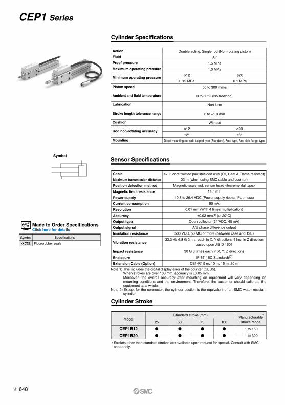
Cylinder Specifications
ø12
0.15 MPa
ø20
0.1 MPa
ø12
±2°
ø20
±3°
ø7, 6 core twisted pair shielded wire (Oil, Heat & Flame resistant)
Sensor Specifications
Cylinder Stroke
Model
CEP1B12
CEP1B20
Standard stroke (mm)Manufacturable
stroke range25 50 75 100
1 to 150
1 to 300
Symbol
∗Strokes other than standard strokes are available upon request for special. Consult with SMC separately.
-XC22 Fluororubber seals
Symbol Specifications
∗
Note 1) This includes the digital display error of the counter (CEU5).When strokes are over 100 mm, accuracy is ±0.05 mm.Moreover, the overall accuracy after mounting on equipment will vary depending on mounting conditions and the environment. Therefore, the customer should calibrate the equipment as a whole.
Note 2) Except for the connector, the cylinder section is the equivalent of an SMC water resistant cylinder.
Cable
Maximum transmission distance
Position detection method
Magnetic field resistance
Power supply
Current consumption
Resolution
Accuracy
Output type
Output signal
Insulation resistance
Vibration resistance
Impact resistance
Enclosure
Extension Cable (Option)
Double acting, Single rod (Non-rotating piston)
Air
1.5 MPa
1.0 MPa
50 to 300 mm/s
0 to 60°C (No freezing)
Non-lube
0 to +1.0 mm
Without
Direct mounting rod side tapped type (Standard), Foot type, Rod side flange type
Action
Fluid
Proof pressure
Maximum operating pressure
Minimum operating pressure
Piston speed
Ambient and fluid temperature
Lubrication
Stroke length tolerance range
Cushion
Rod non-rotating accuracy
Mounting
23 m (when using SMC cable and counter)
Magnetic scale rod, sensor head <Incremental type>
14.5 mT
10.8 to 26.4 VDC (Power supply ripple: 1% or less)
50 mA
0.01 mm (With 4 times multiplication)
±0.02 mm(1) (at 20°C)
Open collector (24 VDC, 40 mA)
A/B phase difference output
500 VDC, 50 MΩ or more (between case and 12E)
33.3 Hz 6.8 G 2 hrs. each in X, Y directions 4 hrs. in Z directionbased upon JIS D 1601
30 G 3 times each in X, Y, Z directions
IP-67 (IEC Standard)(2)
CE1-R∗ 5 m, 10 m, 15 m, 20 m
Made to Order SpecificationsClick here for details
648
CEP1 Series
A

Weight (Sensor cable length 0.5 m, With connector, Without mounting bracket (both ends tapped))
Applicable bore size (mm)
1220
Part no.
DA00032
DA00040
d
M5 x 0.8
M8 x 1.25
H
3
5
B
8
13
C
9.2
15.0
D
7.8
12.5
(mm)
12
20
Cylinder stroke (mm)
25
0.36
0.56
50
0.4
0.62
75
0.44
0.68
100
0.48
0.74
(kg)
Note) For the type with a sensor cable length of 0.5m and without connector (CE1-Z), 40g is subtracted from the weight shown above.For the type with a sensor cable length of 3m and connector (CE1-L), add 160g to the weight shown above.For the type with a sensor cable length of 3m and without connector (CE1-ZL), add 120g to the weight shown above.
Mounting Bracket
Bore size(mm)
12
0.045
0.035
20
0.1
0.045
(kg)
Note 1) Including mounting bolt.Note 2) The foot shows the weight for one set (2 pcs.).
Rod End Nut Dimensions
Auto Switch Proper Mounting Position
Regarding dimensions for the auto switch proper mounting position (at stroke end), refer to page 655.
Material ø12, 20: Steel(2 pcs. are attached as standard.)
Electrical Wiring
SignalWire color
White
Yellow
Brown
Blue
Red
Black
—
Contact signal
A
B
C
D
E
F
G
Signal name
A phase
B phase
COM (0 V)
COM (0 V)
+12 to 24 V
0 V
Shield
G
F
DC
B
A
E
H
0.04
Stroke reading cylinder
0.08 0.12
B
C
d
D
H
30°
Output typeThe output signal of the high precision stroke reading cylinder is A/B phase difference output (open collector output) as shown in the figure below.The relation between the movement distance and the signal output of the high precision stroke reading cylinder is that for each 0.04 mm of movement a one pulse signal is output to both output terminals A and B. In order to measure with a discrimination of 0.01 mm, a counter with a 4 times multiplication function (CEU5) is required.
A phase output
B phase output
Stroke reading cylindermovement in mm
(White)
(Yellow)
Connector pin arrangement
A phase(White)
B phase(Yellow)
Output circuit of stroke reading cylinder
COM (blue, brown)(0 V)
Input/OutputThe input/output of the stroke reading cylinder is performed by a ø7 shielded twisted pair wire from the sensor section plus a connector.
CEP1 SeriesHigh Precision Stroke Reading Cylinder
Non-rotating Piston Type
Rod side flange (F)
Foot (L)
649
CEP1
CE1
CE2
ML2B
D-
-X
CEP1
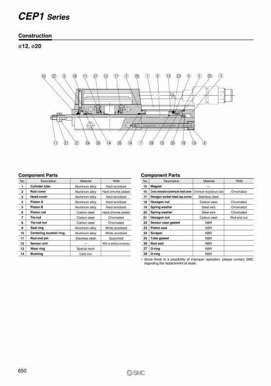
Construction
1
2
3
4
5
6
7
8
9
10
11
12
13
14
Aluminum alloy
Aluminum alloy
Aluminum alloy
Aluminum alloy
Aluminum alloy
Carbon steel
Carbon steel
Carbon steel
Aluminum alloy
Aluminum alloy
Stainless steel
—
Special resin
Cast iron
Hard anodized
Hard chrome plated
Hard anodized
Hard anodized
Hard anodized
Hard chrome plated
Chromated
Chromated
White anodized
White anodized
Quenched
With or without connector
Cylinder tube
Rod cover
Head cover
Piston A
Piston B
Piston rod
Tie-rod
Tie-rod nut
Seal ring
Centering location ring
Rod end pin
Sensor unit
Wear ring
Bushing
22
23
24
25
26
27
28
Component Parts Component Parts
15
16
17
18
19
20
21
—
Chromium molybdenum steel
Stainless steel
Carbon steel
Steel wire
Steel wire
Carbon steel
NBR
NBR
NBR
NBR
NBR
NBR
NBR
Chromated
Chromated
Chromated
Chromated
Rod end nut
Magnet
Cross recessed countersunk head screw
Hexagon socket head cap screw
Hexagon nut
Spring washer
Spring washer
Hexagon nut
Sensor case gasket
Piston seal
Scraper
Tube gasket
Rod seal
O-ring
O-ring
ø12, ø20
Description Material NoteNo. Description Material NoteNo.
∗ Since there is a possibility of improper operation, please contact SMC regarding the replacement of seals.
!0 @2 !6o !7 !7@7 !2 w @5 q y !3 @3 r t @5 e
!1 @1 @1 @6@6@4 !4!4 u @8 !5 @0 !9!8 i
650
CEP1 Series
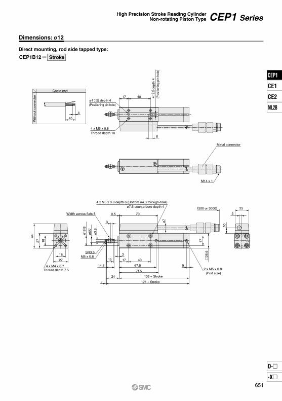
CEP1B12
Cable end
45
4
26
.6
17
5
71.5
103 + Stroke
127 + Stroke
67.5
4017
3
13
14.5
2
24
ø7
2 x M5 x 0.8
4 x M5 x 0.8 depth 6 (Bottom ø4.3 through-hole)
700.5
3
ø18f
8
ø6f7
ø3.8
SR3.5M5 x 0.8
4 x M4 x 0.7
27
18
44
27 18
Direct mounting, rod side tapped type:
Stroke
With
out c
onne
ctor
(Port size)
ø7.5 counterbore depth 4
Width across flats 8
Thread depth 7.5
M14 x 1
Metal connector
(500 or 3000)
5
25
10
17
6
40
4 x M5 x 0.8Thread depth 10
+ 0.05 + 0.02 ø4 depth 4
(Positioning pin hole)
+ 0
.05
+ 0
.02
4
dept
h 4
(Pos
ition
ing
pin
hole
)
Dimensions: ø12
CEP1 SeriesHigh Precision Stroke Reading Cylinder
Non-rotating Piston Type
651
CEP1
CE1
CE2
ML2B
D-
-X
CEP1

CEP1L12
17
3.527
47.5
51
40
2718
5.538
6
504 x ø4.5
Foot type:
Stroke
CEP1F12
Rod side flange type:
Stroke
+ 0
.05
+ 0
.02
4 (P
ositi
onin
g pi
n ho
le)
+ 0.05 + 0.02 ø4
(Positioning pin hole)
5466
5.5
13
40
25
6
4 x ø4.5
+ 0
.05
+ 0
.02
4 (P
ositi
onin
g pi
n ho
le)
Dimensions: ø12
652
CEP1 Series

Dimensions: ø20
Cable end
4
45
35
.6
23
7 2 x M5 x 0.8
ø7
74
114 + Stroke
145 + Stroke
70
40183
18
20
2
31
701.5
5
ø22
f8
ø10
f7
ø6
SR6M8 x 1.25
4 x M5 x 0.8
36
23
53
36 23
Width across flats 13
CEP1B20
Direct mounting, rod side tapped type:
Stroke
5
25
10
With
out c
onne
ctor
4 x M6 x 1.0 depth 6.5 (Bottom ø5.3 through-hole)ø9.5 counterbore depth 5.5
(Port size)Thread depth 10
Metal connector
M14 x 1
(500 or 3000)
18 40
6
+ 0.05 + 0.02 ø4 depth 4
(Positioning pin hole)
4 x M6 x 1.0Thread depth 12
+ 0
.05
+ 0
.02
4
dept
h 4
(Pos
ition
ing
pin
hole
)
CEP1 SeriesHigh Precision Stroke Reading Cylinder
Non-rotating Piston Type
653
CEP1
CE1
CE2
ML2B
D-
-X
CEP1
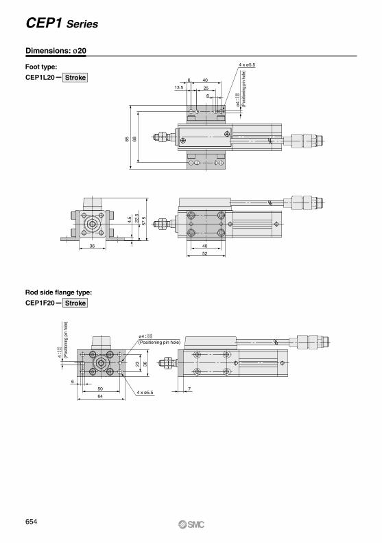
22.5
4.5
57.5
52
4036
50
6
64
23 36
4 x ø5.57
CEP1L20
Foot type:
Stroke
CEP1F20
Rod side flange type:
Stroke
+ 0
.05
+ 0
.02
4 (P
ositi
onin
g pi
n ho
le)
+ 0.05 + 0.02 ø4
(Positioning pin hole)
6885
13.5 25
6
406
4 x ø5.5
+ 0
.05
+ 0
.02
ø
4(P
ositi
onin
g pi
n ho
le)
Dimensions: ø20
654
CEP1 Series
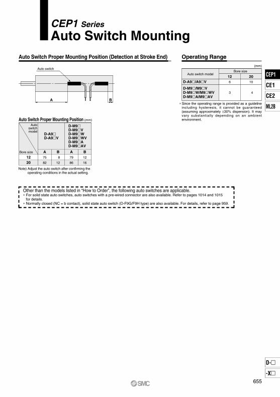
Auto Switch Proper Mounting Position (Detection at Stroke End)
A B
Auto switch
Auto Switch Proper Mounting Position
Bore size
Autoswitchmodel
D-A9D-A9V
A75
82
B 8
12
D-M9D-M9VD-M9WD-M9WVD-M9AD-M9AV
A79
86
B12
16
1220
(mm)
Operating Range
Auto switch modelBore size
126
3
2010
4
D-A9/A9V
D-M9/M9VD-M9W/M9WVD-M9A/M9AV
(mm)
Other than the models listed in “How to Order”, the following auto switches are applicable.∗ For solid state auto switches, auto switches with a pre-wired connector are also available. Refer to pages 1014 and 1015 for details.∗ Normally closed (NC = b contact), solid state auto switch (D-F9G/F9H type) are also available. For details, refer to page 959.
Note) Adjust the auto switch after confirming the operating conditions in the actual setting.
∗Since the operating range is provided as a guideline including hysteresis, it cannot be guaranteed(assuming approximately ±30% dispersion). It may vary substantially depending on an ambient environment.
655
CEP1 Series
Auto Switch Mounting
CEP1
CE1
CE2
ML2B
D-
-X
CEP1
∗1 Water resistant type auto switches can be mounted on the above models, but in such case SMC cannot guarantee water resistance.Consult with SMC regarding water resistant types with the above model numbers.
∗2 1 m type lead wire is only applicable to D-A93.
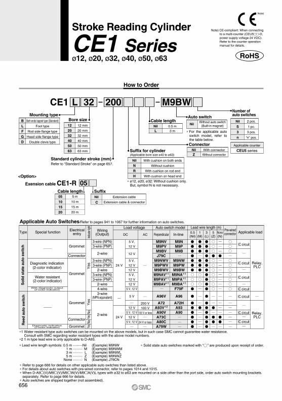
CE1 32 200
NilWithout auto switch
(Built-in magnet)
Both ends tapped type (Standard)
Foot type
Rod side flange type
Head side flange type
Double clevis type
Mounting typeBLFGD
12 mm
20 mm
32 mm
40 mm
50 mm
63 mm
Bore size122032405063
Nil
NRH
With cushion on both ends
Without cushion
With cushion on rod end
With cushion on head end
With connectorWithout connector
2 pcs.
1 pc.
3 pcs.
“n” pcs.
Auto switchNil
S
3
n
ConnectorNilZ
Applicable counter
CEU5 series
Cable length05101520
5 m
10 m
15 m
20 m
SuffixNil
C
Extension cable
Extension cable & connector
05
0.5 m3 m
NilL
Cable length
L M9BW
Grommet
Connector
Grommet
Connector
Grommet
Grommet
200 V100 V
100 V or less
24 V or less
3-wire(NPN equivalent)
2-wire
DC
24 V
24 V
5 V
12 V5 V, 12 V
12 V5 V, 12 V
5 V,12 V
12 V
5 V,12 V12 V5 V,12 V12 V
5 V, 12 V
AC
A96V
A72A93V∗2
A90VA73CA80CA79W
M9NVM9PVM9BVJ79C
M9NWVM9PWVM9BWVM9NAV∗1
M9PAV∗1
M9BAV∗1
A96
A72HA93A90
M9NM9PM9B
M9NWM9PWM9BW
M9NA∗1
M9PA∗1
M9BA∗1
F79F
Standard cylinder stroke (mm)Refer to “Standard Stroke” on page 657.
Exension cable CE1-R<Option>
∗ ø12, ø20, ø32: Without cushion only. But, symbol N is not necessary.
Suffix for cylinder(Applicable bore size ø40 to ø63)
∗ For the applicable auto switch model, refer to the table below.
Number ofauto switches
∗ Solid state auto switches marked with “ ” are produced upon receipt of order.∗ Lead wire length symbols: 0.5 m ·········· Nil (Example) M9NW 1 m ·········· M (Example) M9NWM 3 m ·········· L (Example) M9NWL 5 m ·········· Z (Example) M9NWZ None ·········· N (Example) J79CN
∗ Refer to page 666 for details on other applicable auto switches than listed above.∗ For details about auto switches with pre-wired connector, refer to pages 1014 and 1015.∗ When D-A9(V)/M9(V)/M9W(V)/M9A(V)L types with ø32 to ø63 are mounted on a side other than the port side, order auto switch mounting brackets.
separately. Refer to page 666 for details. ∗ Auto switches are shipped together (not assembled).
Type Special function Electricalentry
Load voltageWiring
(Output)Pre-wiredconnector Applicable load
Auto switch model Lead wire length (m)
Perpendicular In-line 0.5(Nil)
1(M)
3(L)Ind
icator
light
5(Z)
None(N)
IC circuit
IC circuit
IC circuit
IC circuit
IC circuit
IC circuit
IC circuit
Relay,PLC
Relay,PLC
3-wire (NPN)3-wire (PNP)
2-wire
3-wire (NPN)3-wire (PNP)
2-wire3-wire (NPN)3-wire (PNP)
2-wire4-wire
NoNo
Yes
Yes
Yes
Yes
Ree
d a
uto
sw
itch
So
lid s
tate
au
to s
witc
h
Diagnostic indication(2-color indicator)
Diagnostic indication(2-color indicator)
With diagnostic output(2-color indicator)
Water resistant(2-color indicator)
Applicable Auto Switches/Refer to pages 941 to 1067 for further information on auto switches.
How to Order
RoHS
Note)
Note) CE-compliant: When connecting to a multi-counter (CEU5-D, power supply voltage 24 VDC).Refer to the counter operation manual for details.
656
Stroke Reading Cylinder
CE1 Seriesø12, ø20, ø32, ø40, ø50, ø63
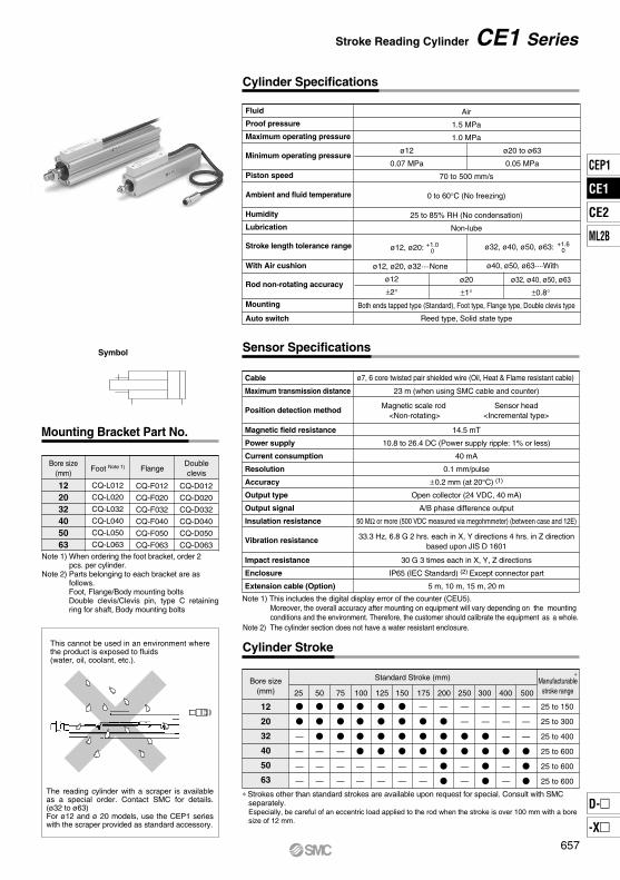
Cylinder Specifications
Air
1.5 MPa
1.0 MPa
70 to 500 mm/s
0 to 60°C (No freezing)
25 to 85% RH (No condensation)
Non-lube
ø12
0.07 MPa
ø20 to ø63
0.05 MPa
ø12
±2°ø32, ø40, ø50, ø63
±0.8°
ø12, ø20:
ø12, ø20, ø32····None
+1.00 ø32, ø40, ø50, ø63:
ø40, ø50, ø63····With
+1.60
Sensor Specifications
Cylinder Stroke
12
20
32
40
50
63
25 50 10075 125 150
25 to 150
25 to 300
25 to 400
25 to 600
25 to 600
25 to 600
175 200 250 300 400 500
Standard Stroke (mm)Bore size(mm)
Symbol
122032405063
CQ-L012
CQ-L020
CQ-L032
CQ-L040
CQ-L050
CQ-L063
CQ-F012
CQ-F020
CQ-F032
CQ-F040
CQ-F050
CQ-F063
CQ-D012
CQ-D020
CQ-D032
CQ-D040
CQ-D050
CQ-D063
Foot Note 1) FlangeBore size
(mm)Doubleclevis
Mounting Bracket Part No.
This cannot be used in an environment where the product is exposed to fluids (water, oil, coolant, etc.).
The reading cylinder with a scraper is available as a special order. Contact SMC for details. (ø32 to ø63)For ø12 and ø 20 models, use the CEP1 series with the scraper provided as standard accessory.
Note 1) When ordering the foot bracket, order 2 pcs. per cylinder.Note 2) Parts belonging to each bracket are as follows.
Foot, Flange/Body mounting boltsDouble clevis/Clevis pin, type C retaining ring for shaft, Body mounting bolts
Fluid
Proof pressure
Maximum operating pressure
Minimum operating pressure
Piston speed
Ambient and fluid temperature
Humidity
Lubrication
Stroke length tolerance range
With Air cushion
Rod non-rotating accuracy
Mounting
Auto switch
ø20
±1°
Both ends tapped type (Standard), Foot type, Flange type, Double clevis type
Reed type, Solid state type
Manufacturablestroke range
∗
∗Strokes other than standard strokes are available upon request for special. Consult with SMC separately.Especially, be careful of an eccentric load applied to the rod when the stroke is over 100 mm with a bore size of 12 mm.
Note 1) This includes the digital display error of the counter (CEU5). Moreover, the overall accuracy after mounting on equipment will vary depending on the mounting conditions and the environment. Therefore, the customer should calibrate the equipment as a whole.
Note 2) The cylinder section does not have a water resistant enclosure.
Cable
Maximum transmission distance
Position detection method
Magnetic field resistance
Power supply
Current consumption
Resolution
Accuracy
Output type
Output signal
Insulation resistance
Vibration resistance
Impact resistance
Enclosure
Extension cable (Option)
ø7, 6 core twisted pair shielded wire (Oil, Heat & Flame resistant cable)
33.3 Hz, 6.8 G 2 hrs. each in X, Y directions 4 hrs. in Z directionbased upon JIS D 1601
23 m (when using SMC cable and counter)
14.5 mT
10.8 to 26.4 DC (Power supply ripple: 1% or less)
40 mA
0.1 mm/pulse
±0.2 mm (at 20°C) (1)
Open collector (24 VDC, 40 mA)
A/B phase difference output
50 MΩ or more (500 VDC measured via megohmmeter) (between case and 12E)
30 G 3 times each in X, Y, Z directions
IP65 (IEC Standard) (2) Except connector part
5 m, 10 m, 15 m, 20 m
Magnetic scale rod <Non-rotating>
Sensor head<Incremental type>
657
Stroke Reading Cylinder CE1 Series
CEP1
CE1
CE2
ML2B
D-
-X
CE1
12
20
32
40
50
63
0.28
0.48
—
—
—
—
25
0.32
0.55
0.84
—
—
—
50
0.39
0.69
1.05
1.58
—
—
100
0.35
0.62
0.95
—
—
—
75
0.42
0.76
1.16
1.71
—
—
125
0.46
0.83
1.26
1.83
—
—
150
—
0.9
1.37
1.96
—
—
175
—
0.97
1.48
2.08
3.26
4.04
200
—
—
1.69
2.33
—
—
250
—
—
—
3.08
—
—
400
—
—
1.9
2.58
3.96
4.84
300
—
—
—
3.58
5.36
6.44
500
Cylinder stroke (mm)Bore size(mm)
A phase(White)
B phase(Yellow)
COM (blue, brown)(0 V)
Part no.
NTJ-015ANT-02 NT-04 NT-05
12
20
32 . 40
50 . 63
d
M5 x 0.8
M8 x 1.25
M14 x 1.5
M18 x 1.5
H
4
5
8
11
B
8
13
22
27
C
9.2
15.0
25.4
31.2
D
7.8
12.5
21.0
26
(kg)
(1 pc. is attached as standard.)
(mm)
B
C
d
D
H
30°
0.1
Stroke reading cylinder
0.2 0.3
A phase output
B phase output
Auto Switch Proper Mounting Position
SignalWire color
White
Yellow
Brown
Blue
Red
Black
—
Contact signal
A
B
C
D
E
F
G
Signal name
A phase
B phase
COM (0 V)
COM (0 V)
+12 to 24 V
0 V
Shield
Connector pin arrangement
G
F
DC
B
A
E
H
Output circuit of stroke reading cylinder
Regarding dimensions for the auto switch proper mounting position (at stroke end), refer to page 665.
Material ø12, 20: Steelø32 to ø63: Rolled steel
Applicable boresize (mm)
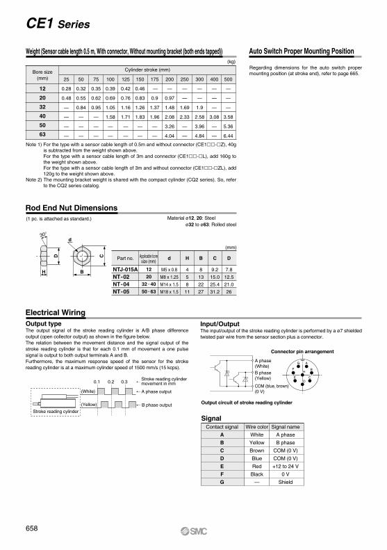
Input/OutputThe input/output of the stroke reading cylinder is performed by a ø7 shielded twisted pair wire from the sensor section plus a connector.
Output typeThe output signal of the stroke reading cylinder is A/B phase difference output (open collector output) as shown in the figure below.The relation between the movement distance and the signal output of the stroke reading cylinder is that for each 0.1 mm of movement a one pulse signal is output to both output terminals A and B.Furthermore, the maximum response speed of the sensor for the stroke reading cylinder is at a maximum cylinder speed of 1500 mm/s (15 kcps).
Stroke reading cylindermovement in mm
(White)
(Yellow)
Rod End Nut Dimensions
Electrical Wiring
Note 1) For the type with a sensor cable length of 0.5m and without connector (CE1-Z), 40g is subtracted from the weight shown above.For the type with a sensor cable length of 3m and connector (CE1-L), add 160g to the weight shown above.For the type with a sensor cable length of 3m and without connector (CE1-ZL), add 120g to the weight shown above.
Note 2) The mounting bracket weight is shared with the compact cylinder (CQ2 series). So, refer to the CQ2 series catalog.
658
Weight (Sensor cable length 0.5 m, With connector, Without mounting bracket (both ends tapped))
CE1 Series
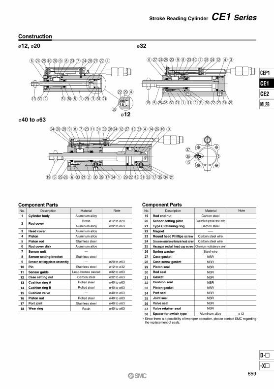
1
2
3
4
5
6
7
8
9
10
11
12
13
14
15
16
17
18
Description
Aluminum alloy
Brass
Aluminum alloy
Aluminum alloy
Aluminum alloy
Stainless steel
Aluminum alloy
—
Stainless steel
—
Stainless steel
Lead-bronze casted
Carbon steel
Rolled steel
Rolled steel
—
Rolled steel
Stainless steel
Resin
Cylinder body
Rod cover
Head cover
Piston
Piston rod
Rod cover disk
Sensor unit
Sensor setting bracket
Sensor setting piece assembly
Pin
Sensor guide
Case setting nut
Cushion ring A
Cushion ring B
Cushion valve
Piston nut
Port joint
Wear ring
Component Parts Component Parts
19
20
21
22
23
24
25
26
27
28
29
30
31
32
33
34
35
36
37
38
Carbon steel
Cold rolled special steel strip
Carbon steel
—
Carbon steel wire
Carbon steel wire
Chromium molybdenum steel
Steel wire
NBR
NBR
NBR
NBR
NBR
NBR
NBR
NBR
NBR
NBR
NBR
Aluminum alloy ø12
Rod end nut
Sensor setting plate
Type C retaining ring
Magnet
Round head Phillips screw
Cross recessed countersunk head screw
Hexagon socket head cap screw
Spring washer
Case gasket
Case screw gasket
Piston seal
Rod seal
Gasket
Cushion seal
Piston gasket
Port seal
Joint seal
Valve seal
Valve retainer seal
Spacer for switch type
ø40 to ø63
ø32
ø12 to ø20
ø32 to ø63
ø20 to ø63
ø12 to ø32
ø32 to ø63
ø32 to ø63
ø40 to ø63
ø40 to ø63
ø40 to ø63
ø40 to ø63
ø40 to ø63
ø40 to ø63
Material NoteNo. Description Material NoteNo.
∗ Since there is a possibility of improper operation, please contact SMC regarding the replacement of seals.
!9 #0w #1 #0 t q e@9 #1@1!9 t@5@6 @1#0 q !1w#1 #0@2@9 #1 @1
@7@4@8 @0 oi@3!0 u@8 @4 !2 rey@4 @8 @0!0 i@3o @4@8@7u @2 ry
r@9@2
#8
@0@4 @8 iuo @3!1 #1 #2@8@4 !2 @7 !3#3 r!4 e!6@6
!9 @5t @6 y #0w@1#0 #5 !7 #4 q @9@2!8#1 #2 !7 #5 #4 @1
#7
#6!5
Construction
ø12, ø20
Stroke Reading Cylinder CE1 Series
ø12
659
CEP1
CE1
CE2
ML2B
D-
-X
CE1
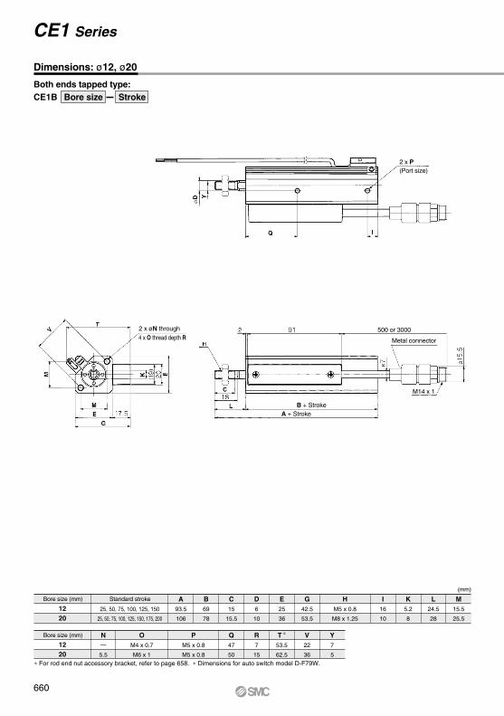
CE1BBoth ends tapped type:
1220
25, 50, 75, 100, 125, 150
25, 50, 75, 100, 125, 150, 175, 200
93.5
106
1220
—
5.5
M4 x 0.7
M6 x 1
M5 x 0.8
M5 x 0.8
69
78
15
15.5
6
10
25
36
42.5
53.5
47
50
7
15
53.5
62.5
22
36
7
5
M5 x 0.8
M8 x 1.25
16
10
5.2
8
24.5
28
15.5
25.5
A
N O P
B C D E G
Q R T ∗ V Y
H I K L M
Bore size Stroke
Bore size (mm)
Bore size (mm)
Standard stroke
∗ For rod end nut accessory bracket, refer to page 658. ∗ Dimensions for auto switch model D-F79W.
(mm)
(Port size)2 x P
500 or 3000
Metal connector
M14 x 1
B + StrokeA + Stroke
4 x O thread depth R2 x øN through
Dimensions: ø12, ø20
CE1 Series
660
Bore size(mm)
1220
Foot typeCommon Rod side flange, Head side flange Double clevis type
A106
121
OM4 x 0.7
M6 x 1
LA4.5
5.8
LB8
9.2
LD4.5
6.6
LE29.5
42
LH17
24
LL2
3.2
LS85
96.4
LX34
48
LY52
66.5
LZ44
62
FD4.5
6.6
FL5.5
8
FV25
39
FX45
48
FZ55
60
Head side flange
A99
114
A113.5
133
CD5
8
CL107.5
124
CU7
12
CW14
18
CX5
8
CZ10
16
RR6
9
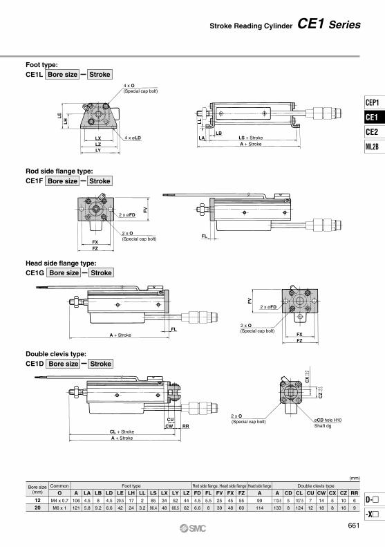
CE1LFoot type:
CE1FRod side flange type:
CE1GHead side flange type:
CE1DDouble clevis type:
4 x øLD
2 x øFD
4 x O
2 x O
LE
LH
FV
LX
FXFZ
2 x øFD
2 x O
FV
FXFZ
LZLY
2 x O
CZ
CX
(Special cap bolt)
(Special cap bolt)
Bore size Stroke
Bore size Stroke
(Special cap bolt)
(Special cap bolt)
–0.
1–
0.3
+0.
4+
0.2
øCD hole H10Shaft dg
LL
LALB
LS + StrokeA + Stroke
FL
A + StrokeFL
CL + StrokeA + Stroke
RRCU
CW
661
Stroke Reading Cylinder CE1 Series
Bore size Stroke
Bore size Stroke
(mm)
CEP1
CE1
CE2
ML2B
D-
-X
CE1
øD
I
2.5 91 500 or 3000
Q
L
X
C
H
ø7
M14 x 1
ø15
.5
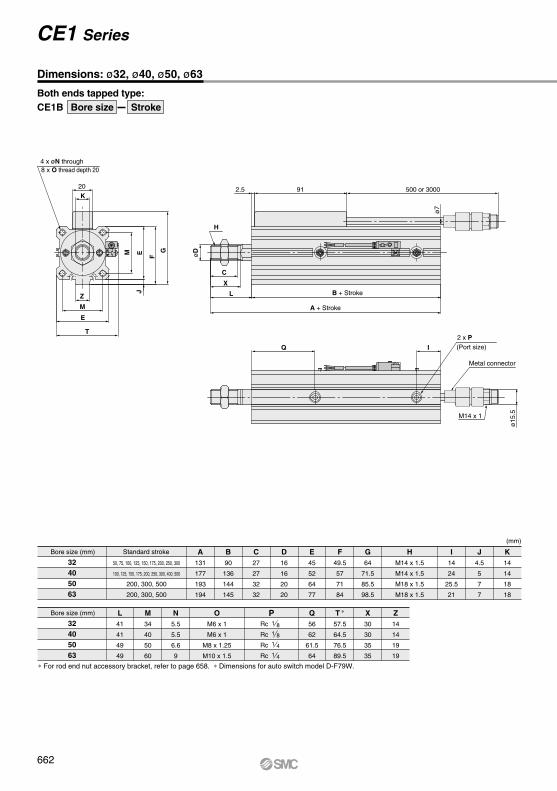
CE1BBoth ends tapped type:
32405063
50, 75, 100, 125, 150, 175, 200, 250, 300
100, 125, 150, 175, 200, 250, 300, 400, 500
200, 300, 500
200, 300, 500
A131
177
193
194
B90
136
144
145
C27
27
32
32
D16
16
20
20
E45
52
64
77
F49.5
57
71
84
G64
71.5
85.5
98.5
I14
24
25.5
21
J4.5
5
7
7
K14
14
18
18
32405063
L41
41
49
49
M34
40
50
60
N5.5
5.5
6.6
9
OM6 x 1
M6 x 1
M8 x 1.25
M10 x 1.5
Rc
Rc
Rc
Rc
Q56
62
61.5
64
T ∗
57.5
64.5
76.5
89.5
X30
30
35
35
Z14
14
19
19
HM14 x 1.5
M14 x 1.5
M18 x 1.5
M18 x 1.5
20
4 x øN through
K
Z
M
E
T
GM EJ
F
Metal connector
2 x P
A + Stroke
B + Stroke
Bore size Stroke
8 x O thread depth 20
(Port size)
Bore size (mm)
Bore size (mm)
Standard stroke
1 81 8
1 4
1 4
P
∗ For rod end nut accessory bracket, refer to page 658. ∗ Dimensions for auto switch model D-F79W.
662
Dimensions: ø32, ø40, ø50, ø63
CE1 Series
(mm)
3.2
FL
LBLA
A + Stroke
A + Stroke
LS + Stroke
A + StrokeFL
CW RR
CU
A + Stroke
CL + Stroke
Bore size(mm)
32405063
Foot type Rod side flange, Head side flange Double clevis type
A148
195.2
215.7
219.2
OM6 x 1
M6 x 1
M8 x 1.25
M10 x 1.5
LA5.8
7
8
9
LB11.2
11.2
14.7
16.2
LD6.6
6.6
9
11
LE52.5
59
71
84.5
LH30
33
39
46
LS112.4
158.4
173.4
177.4
LT∗
65
71.5
83.5
97
LX57
64
79
95
LY72.5
79.5
94
109.5
LZ71
78
95
113
FD5.5
5.5
6.6
9
FG69.5
76.5
91
107
FL8
8
9
9
FT∗
59
65.5
78
91
FV48
54
67
80
FX56
62
76
92
FZ65
72
89
108
M34
40
50
60
A139
185
202
203
Rod sideflange
A131
177
193
194
A161
209
235
238
CD10
10
14
14
CL151
199
221
224
CU14
14
20
20
CW20
22
28
30
CX18
18
22
22
CZ36
36
44
44
RR10
10
14
14
T57.5
64.5
76.5
89.5
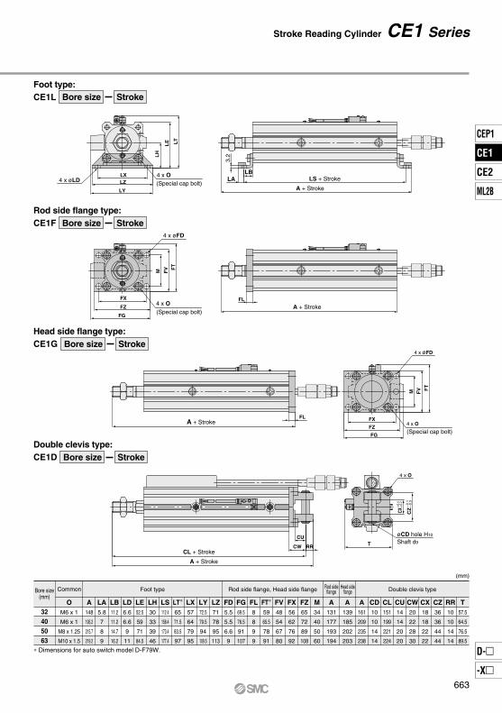
CE1LFoot type:
Bore size Stroke
Bore size Stroke
Bore size Stroke
Bore size Stroke
CE1FRod side flange type:
CE1GHead side flange type:
CE1DDouble clevis type:
4 x O4 x øLD
4 x øFD
øCD hole H10
FVM F
T
FX
FZ
FG
LXLZ
LY
FX
FZ
FG
FVM F
T
LH
LE LT
CX CZ
4 x øFD
4 x O
4 x O
4 x O
T
(Special cap bolt)
(Special cap bolt)
(Special cap bolt)
–0.
1–
0.3
+0.4
+0.2
Shaft d9
Head sideflange
∗ Dimensions for auto switch model D-F79W.
663
Common
(mm)
Stroke Reading Cylinder CE1 Series
CEP1
CE1
CE2
ML2B
D-
-X
CE1
≅U
≅U
≅U BA
BA
25
≅U
ø32 to ø63
ø12 to ø20
ø32 to ø63
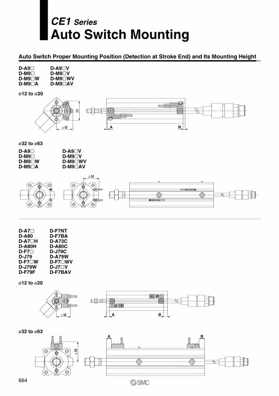
D-A7D-A80D-A7HD-A80HD-F7D-J79D-F7WD-J79WD-F79F
D-F7NTD-F7BAD-A73CD-A80CD-J79CD-A79WD-F7WVD-J7VD-F7BAV
ø12 to ø20
D-A9V D-M9VD-M9WVD-M9AV
D-A9D-M9D-M9WD-M9A
D-A9D-M9D-M9WD-M9A
D-A9VD-M9VD-M9WVD-M9AV
Auto Switch Proper Mounting Position (Detection at Stroke End) and Its Mounting Height
BA
664
CE1 Series
Auto Switch Mounting

Auto Switch Mounting Height
122032405063
U19.524.531.535 41 47.5
U20.525.532.536 42 48.5
U26.531.538.542 48 54.5
U23 28 35 38.544.551
U26 31 38 41.547.554
U22 27 34 37.543.550
U20.525.527 30.536.540
U20.525.529 32.538.542
D-A7D-A80
D-A7HD-A80HD-F7D-J79D-F7WD-J79WD-F7BAD-F79FD-F7NT
D-A73CD-A80C
D-F7VD-F7WVD-F7BAV
D-J79C D-A79WD-A9VD-M9VD-M9WVD-M9AV
(mm)
Bore size (mm)
Auto switchmodel
∗ Auto switch mounting brackets BQ2-012 are not used for sizes over ø32 of D-A9V/M9V/M9WV/M9AVL types. In that case, the above values indicate the operating range when mounted with the current auto switch installation groove.
Note) Adjust the auto switch after confirming the operating conditions in the actual setting.
122032405063
(mm)
Bore size (mm)
Auto switchmodel
D-A73D-A80 D-F7NTD-A9
D-A9V
D-M9D-M9VD-M9WD-M9WVD-M9AD-M9AV
A43.552.560.584.587.591
B12 18.522.544.549.547
D-A79W
A35.544.552.576.579.583
B 4.510.514.536.541.539
A38 47 55 79 82 85.5
B 6.513 17 39 44 41.5
A41 50 58 82 85 88.5
B 9.516 20 42 47 44.5
A37 46 54 78 81 84.5
B 5.5 12 16 38 43 40.5
D-A72/A7H/A80HD-A73C/A80C/F7D-F79F/J79/F7VD-J79C/F7WD-J79W/F7WVD-F7BAV/F7BA
A38.547.555 79.582.586
B7
13.517.539.544.542
Auto Switch Proper Mounting Position
No. of autoswitchesmounted
1 pc.
2 pcs.
5
5
5
10
10
15
15 (5)
15 (5)
15
20
20 (10)
20 (15)
(mm)
D-M9VD-F7VD-J79C
D-A9VD-A7D-A80D-A73CD-A80C
D-M9WVD-M9AVD-F7WVD-F7BAVL
D-M9D-F7D-J79
15 (10)
15
D-M9WD-M9A
15 (5)
15 (10)
D-A7HD-A80H D-A79W
D-F7WD-J79WD-F7BAD-F79FD-F7NT
10 (5)
10
D-A9
Note) The dimensions stated in ( ) shows the minimum stroke for the auto switch mounting when the auto switch does not project from the end surface of the cylinder body and hinder the lead wire bending space. (Refer to the figure below.)Order auto switches and auto switch mounting brackets separately.
Auto switch modelBore size (mm)
7
2.5
9
4
9.5
6 6 6 6.5
9.5 9.5 11.5
12 20 32 40 50 63D-A9(V)
D-A79W
(mm)
D-A7(H)(C)D-A80(H)(C)
D-F7(V)D-J79(C)D-F7W(V)D-F7BA(V)D-F7NTD-F79F
9.5 12 12 11 10 12
11.5 13 13 14 14 16
4 5.5 6 6 6 6.5
D-M9(V)D-M9W(V)D-M9A(V)
Auto Switch Proper Mounting Position (Detection at Stroke End) and Its Mounting Height
∗ Since the operating range is provided as a guideline including hysteresis, it cannot be guaranteed (assuming approximately ±30% dispersion). It may vary substantially depending on an ambient environment. 665
Operating Range
Minimum Auto Switch Mounting Stroke
Auto Switch Mounting CE1 Series
CEP1
CE1
CE2
ML2B
D-
-X
CE1
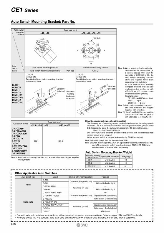
Note 1) When a compact auto switch is mounted on the three sides (A, B and C above) other than the port side of CE132 to 50, the auto switch mounting brackets above are required. Order them separately from cylinders.(It is the same as when mounting compact cylinders with an auto switch mounting rail, but not with CE163 to 100 compact auto switch installation groove.)Example order:
CE1B32-100-M9BW ······ 1 unitBQ-2 ······ 2 pcs.BQ2-012 ······ 2 pcs.
Note 2) Auto switch mounting brackets and auto switches are shipped together with cylinders.
Note 3) D-A9 and D-A9V auto switches cannot be used with the product with a bore size of ø12 (CE112).
Auto Switch Mounting Bracket: Part No.
D-A9D-A9VD-M9D-M9VD-M9WD-M9WVD-M9AD-M9AV
Auto switchmounting surface
Auto switchmodel
Bore size (mm)
q BQ-1w BQ2-012Two kinds of auto switch mounting brackets are used as a set.
Auto switch mounting surface
Auto switch mounting rail side only
ø12, ø20
q
w
Auto switch mounting surface
Port side
Auto switchmounting
brackets arenot required.
q BQ-2w BQ2-012Two kinds of auto switch mounting brackets are used as a set.
A, B, C
ø32, ø40, ø50, ø63
q
w
Set screw(not used)
Port side
B
C A
Set screw(not used)
[Mounting screw set made of stainless steel]The following set of mounting screws made of stainless steel (including nuts) is available. Use it in accordance with the operating environment. (Please order BQ-2 separately, since the auto switch spacer (for BQ-2) is not included.)
BBA2: For D-A7/A8/F7/J7 typesD-F7BA/F7BAV auto switches are set on the cylinder with the stainless steel screws above when shipped.When an auto switch is shipped independently, BBA2 is attached.
Bore size (mm)Auto switch model
ø12 to ø20 ø32
Note 4) Auto switch mounting brackets and auto switches are shipped together with cylinders.
Note 5) Refer to page 1051 for the details of BBA2.Note 6) When mounting D-M9A(V) on a port other than the ports for ø32, ø40
and ø50, order auto switch mounting brackets BQ2-012S, BQ-2 and stainless steel screw set BBA2 separately.
ø40 to ø63
D-A7/A80 D-A73C/A80CD-A7H/A80HD-A79WD-F7/J79D-F7VD-J79CD-F7W/J79WD-F7WVD-F7BA/F7BAVD-F79F/F7NT
BQ-1 BQ-2
Auto Switch Mounting Bracket Weight
ø12 to ø20
ø32 to ø63
ø12 to ø63
1.5
1.5
5
Auto switch mountingbracket part no.BQ-1
BQ-2
BQ2-012
Applicable bore size Weight (g)
Other Applicable Auto Switches
∗ For solid state auto switches, auto switches with a pre-wired connector are also available. Refer to pages 1014 and 1015 for details.∗ Normally closed (NC = b contact), solid state auto switch (D-F9G/F9H type) are also available. For details, refer to page 959.
Auto switch type Model FeaturesElectrical entry (Fetching direction)
D-A73
D-A80
D-A73H, A76H
D-A80H
D-F7NV, F7PV, F7BV
D-F7NWV, F7BWV
D-F7BAVL
D-F79, F7P, J79
D-F79W, F7PW, J79W
D-F7BA
D-F7NT
—
Without indicator light
—
Without indicator light
—
Diagnostic indication (2-color indicator)
Water resistant (2-color indicator)
—
Diagnostic indication (2-color indicator)
Water resistant (2-color indicator)
With timer
Grommet (Perpendicular)
Grommet (In-line)
Grommet (Perpendicular)
Grommet (In-line)
Reed
Solid state
666
CE1 Series
How to Order
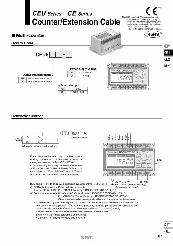
Connection Method
Multi-counter
CEU5
Power supply voltage
External outputNil
B
RS-232C
RS-232C + BCD
Nil
D100 to 240 VAC
24 VDCOutput transistor modeNil
PNPN open collector output
PNP open collector output
MULTI COUNTER:CEU5 A COM COM COMB 12 VDC GND F.G. R.S. HOLD BANK1 BANK2
COM S.STOPOUT1OUT2OUT3OUT4OUT5100 to 240 VAC
COUNT PRESET FUNC.
SD SGRD RS-232C
UP
LEFT RIGHT
DOWN
SEL. SETMODE
MULTI COUNTER:CEU5 A COM COM COMB 12 VDC GND F.G. R.S. HOLD BANK1 BANK2
COM S.STOPOUT1OUT2OUT3OUT4OUT5100 to 240 VAC
COUNT PRESET FUNC.
SD SGRD RS-232C
UP
LEFT RIGHT
DOWN
SEL. SETMODE
BCD
RS-232C
High precision stroke reading cylinder
Extension cable
If the distance between high precision stroke reading cylinder and multi-counter is over 23 meter, use transmission box. (CE1-H0374)When changing the wiring combination of White- A/Blue-COM and Yellow B/Brown-COM to the combination of White B/Blue-COM and Yellow- A/Brown-COM, the counting direction reverses.
BCD output (Refer to page 676.) function is available only for CEU5B-.(1) BCD output connector: D-Sub half pitch connector (Built in CEU5B-D) D x 10M-36S (Made by HIROSE ELECTRIC CO., LTD.)(2) Applicable connectors: D x 30AM-36P (Plug: Made by HIROSE ELECTRIC CO., LTD.) ∗
D x 30M-36-CV (Cover: Made by HIROSE ELECTRIC CO., LTD.)∗
Other interchangeable commercial cables with connectors can be also used. ∗ Pressure welding tools are required to connect the connector (plug, cover) models listed above
and cables (order separately). The following products, including pre-assembled connectors and cables, are also available. Contact the manufacturer (Misumi Corporation) directly.SHPT-H-A-36-∗: Male connector on one end, cable cut off on one endSHPT-HH-A-36-∗: Male connectors on both ends∗ 0.2 to 50 (This shows the cable length. Unit: m)
Whi
te
Blu
e
Yel
low
Bro
wn
Red
Bla
ck
F.G
.
• OUT1 to OUT 5• OUT1 to OUT20 (Bank switching)• Binary output (31 points)
RoHS
Note)
Note) CE-compliant: When connecting to a stroke reading cylinder (CE1), a high precision stroke reading cylinder (CEP1) and a stroke reading cylinder with brake (CE2). (CEU5-D type)Refer to the operation manual for details.
CEU Series CE Series
Counter/Extension Cable
667
CEP1
CE1
CE2
ML2B
D-
-X
CE1

Model
Type
Mounting
Operating system
Operation mode
Reset system
Display system
Number of digits
Memory holding Storage medium
Input signal type
Count input
Pulse signal system
Counting speed
Control signal input
Sensor power supply
Output signal type
Preset output configuration
Output type
Output delay time
Communication system
Output transistor mode
Power supply voltage
Power consumption
Withstand voltage
Insulation resistance
Ambient temperature
Ambient humidity
Noise resistance
Shock resistance
Impact resistance
Weight
CEU5 CEU5-D CEU5P CEU5P-D CEU5B CEU5B-D CEU5PB CEU5PB-D
Multi-counter
Surface mounting (DIN rail or Screw stop)
Adding - subtracting type
Operating mode, Data setting mode, Function setting mode
External reset terminal
LCD (With back light)
6 digits
Setting value (always held), Count value (Hold/Non-hold switching), E2ROM (Warning display after writing approx. 800,000 times: E2FUL)
Count input, Control signal input (Reset, Hold, Bank selection)
No-voltage pulse input
90° phase difference input ∗1/ UP/DOWN separate input ∗2
100 kHz ∗1
Voltage input (12 VDC or 24 VDC)
10.8 to 13.2 VDC, 60 mA
Compare/Hold/One-shot (100 ms fixed pulse)
Separate 5 point output/Binary code output
5 ms or less (for normal output)/60 ms or less (Binary output)
RS-232C
NPN open collectorMax 30 VDC, 50 mA
NPN open collectorMax 30 VDC, 50 mA ∗3
PNP open collectorMax 30 VDC, 50 mA
PNP open collectorMax 30 VDC, 50 mA ∗3
90 to 264 VAC
20 VA or less
21.6 to 26.4 VDC
10 W or less
90 to 264 VAC
20 VA or less
21.6 to 26.4 VDC
10 W or less
90 to 264 VAC
20 VA or less
21.6 to 26.4 VDC
10 W or less
90 to 264 VAC
20 VA or less
21.6 to 26.4 VDC
10 W or less
0 to +50°C (No freezing)
35 to 85% RH (No condensation)
Square wave noise from a noise simulator (pulse duration 1 µs) between power supply terminals ±2000 V, I/O line ±600 V
Endurance 10 to 55 Hz; Amplitude 0.75 mm; X, Y, Z for 2 hours each
Endurance 10 G; X, Y, Z directions, 3 times each
350 g or less
∗1) 90° phase difference input
A :B :C :D : t : 10 µsec or more required
Between case and AC line: 1500 VAC for 1 min.Between case and signal ground: 500 VAC for 1 min.
Between case and AC line: 50 MΩ or more (500 VDC measured via megohmmeter)
Preset output, Cylinder stop output, BCD outputPreset output, Cylinder stop output
Multi-counter/Dimensions
MULTI COUNTER:CEU5 A COM COM COMB 12 VDC GND F.G. R.S. HOLD BANK1 BANK2
COM S.STOPOUT1OUT2OUT3OUT4OUT5100 to 240 VAC
COUNT PRESET FUNC.
SD SGRD RS-232C
UP
LEFT RIGHT
DOWN
SEL. SETMODE
104
107
24 x M3 x 0.5
4 x ø4.5
BCD output connector
33.5
125
59
64
56 35.5
(DIN
rai
l mou
ntin
g)
804
A
I
J
B
t
C D
2.5 µsec or more required
Counting input pulse duration
A phase
B phase
∗ 3) 15 mA when BCD is output (Refer to page 676.)
Counting speed f = = = 100000 Hz
∗ 2) UP/DOWN input Input wave form conditions: At a maximum of 100 kHz, the UP/DOWN wave form should be as shown below.
+12 V±10%
UPpulse
+12 V±10%
DOWNpulse
1t
110 x 10–6
≅ 100 kHz
668
Multi-counter/Specifications
CEU Series
CEU5 Control signal input
COM
1 kΩ
2.2 kΩ
or
(Select Reset/Hold/Bank)
Power supply(24 or 12 VDC)
Control signal input
Load
Load
MaxDC30V, 50mA
OUT1
OUT2
COM
COM
OUT5
COM
Load
Load
Load
MaxDC30V, 50mA
OUT1
OUT2
COM
COM
OUT5
COM
Load
Connection
method
ModelNPN transistor output PNP transistor output
CEU5- CEU5P-
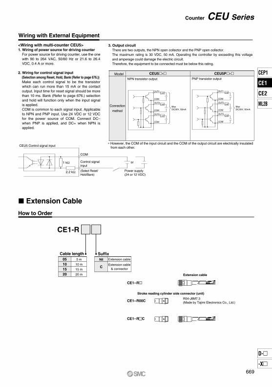
Wiring with External Equipment
∗ However, the COM of the input circuit and the COM of the output circuit are electrically insulated from each other.
<Wiring with multi-counter CEU5>1. Wiring of power source for driving counter
For power source for driving counter, use the one with 90 to 264 VAC, 50/60 Hz or 21.6 to 26.4 VDC, 0.4 A or more.
2. Wiring for control signal input (Selection among Reset, Hold, Bank (Refer to page 676.))
Make each control signal to be the transistor which can run more than 15 mA or the contact output. Input time for reset signal should be more than 10 ms. Bank (Refer to page 676.) selection and hold will function only when the input signal is applied.COM is common to each signal input. Applicable to NPN and PNP input. Use 24 VDC or 12 VDC for the power source of COM. Connect DC– when PNP is applied, and DC+ when NPN is applied.
3. Output circuitThere are two outputs, the NPN open collector and the PNP open collector. The maximum rating is 30 VDC, 50 mA. Operating the controller by exceeding this voltage and amperage could damage the electric circuit. Therefore, the equipment to be connected must be below this rating.
How to Order
Extension Cable
CE1-R
Cable length05101520
5 m
10 m
15 m
20 m
SuffixNil
C
Extension cable
Extension cable& connector
R04-J8M7.3(Made by Tajimi Electronics Co., Ltd.)
CE1–R
CE1–R00C
CE1–R C
Extension cable
Stroke reading cylinder side connector (unit)
669
Counter CEU Series
CEP1
CE1
CE2
ML2B
D-
-X
CE1
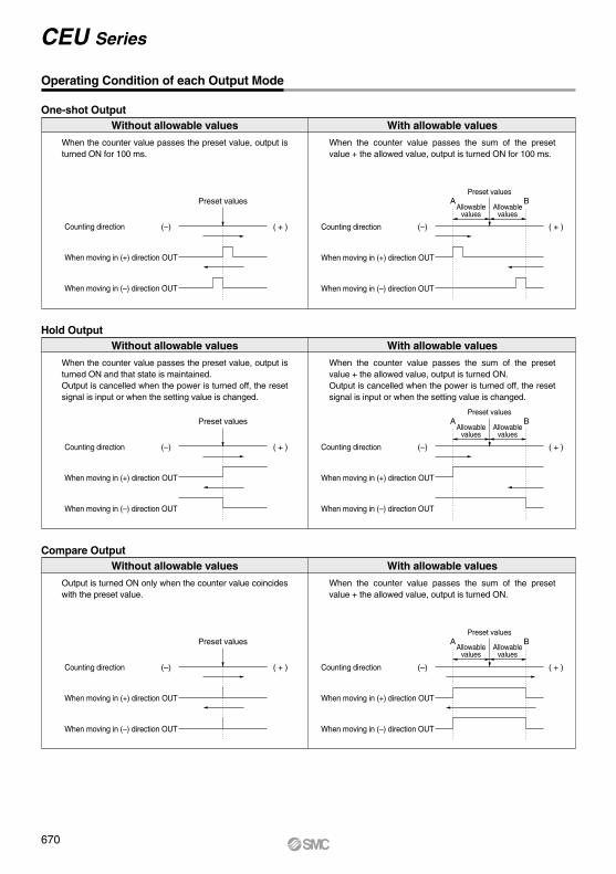
One-shot OutputWith allowable valuesWithout allowable values
When the counter value passes the preset value, output is turned ON for 100 ms.
When the counter value passes the sum of the preset value + the allowed value, output is turned ON for 100 ms.
Hold OutputWith allowable valuesWithout allowable values
When the counter value passes the preset value, output is turned ON and that state is maintained.Output is cancelled when the power is turned off, the reset signal is input or when the setting value is changed.
When the counter value passes the sum of the preset value + the allowed value, output is turned ON.Output is cancelled when the power is turned off, the reset signal is input or when the setting value is changed.
Compare OutputWith allowable valuesWithout allowable values
Output is turned ON only when the counter value coincides with the preset value.
When the counter value passes the sum of the preset value + the allowed value, output is turned ON.
( + ) (–)
Preset values
Counting direction
When moving in (+) direction OUT
When moving in (–) direction OUT
( + ) (–)
Preset values
Counting direction
When moving in (+) direction OUT
When moving in (–) direction OUT
( + ) (–)
Preset values
Counting direction
When moving in (+) direction OUT
When moving in (–) direction OUT
( + ) (–)
Preset values
Allowablevalues
Allowablevalues
A B
Counting direction
When moving in (+) direction OUT
When moving in (–) direction OUT
( + ) (–)
Preset values
Allowablevalues
Allowablevalues
A B
Counting direction
When moving in (+) direction OUT
When moving in (–) direction OUT
( + ) (–)
Preset values
Allowablevalues
Allowablevalues
A B
Counting direction
When moving in (+) direction OUT
When moving in (–) direction OUT
670
Operating Condition of each Output Mode
CEU Series
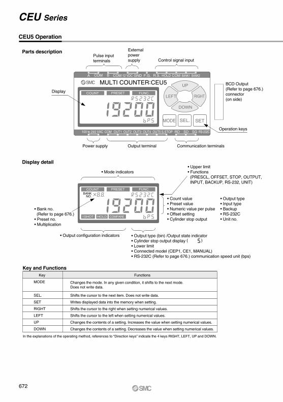
Display detail
Key and Functions
MULTI COUNTER:CEU5 A COM COM COMB 12 VDC GND F.G. R.S. HOLD BANK1 BANK2
COM S.STOPOUT1 OUT2 OUT3 OUT4 OUT5100 to 240 VAC
COUNT PRESET FUNC.
COUNT PRESET FUNC.BANK
NO.
1SHOT HOLD COMPARE
SD SGRD RS-232C
UP
LEFT RIGHT
DOWN
SEL. SETMODE
( )
Key
MODE
SEL.
SET
RIGHT
LEFT
UP
DOWN
Functions
Changes the mode. In any given condition, it shifts to the next mode. Does not write data.
Shifts the cursor to the next item. Does not write data.
Writes displayed data into the memory when setting.
Shifts the cursor to the right when setting numerical values.
Shifts the cursor to the left when setting numerical values.
Changes the contents of a setting. Increases the value when setting numerical values.
Changes the contents of a setting. Decreases the value when setting numerical values.
In the explanations of the operating method, references to “Direction keys” indicate the 4 keys RIGHT, LEFT, UP and DOWN.
Display
Operation keys
BCD Output (Refer to page 676.)connector(on side)
Pulse inputterminals
Power supply Output terminal Communication terminals
Control signal input
Externalpowersupply
• Mode indicators
• Output configuration indicators
• Count value• Preset value• Numeric value per pulse• Offset setting• Cylinder stop output
• Output type• Input type• Backup• RS-232C• Unit no.
• Upper limit• Functions(PRESCL, OFFSET, STOP, OUTPUT,INPUT, BACKUP, RS-232, UNIT)
• Bank no. (Refer to page 676.)• Preset no.• Multiplication
• Output type (bin) /Output state indicator • Cylinder stop output display• Lower limit• Connected model (CEP1, CE1, MANUAL) • RS-232C (Refer to page 676.) communication speed unit (bps)
CEU5 Operation
672
CEU Series
Parts description

1. Explanation of display in count mode
2. Setting of preset mode
Selection of preset No.
• Select a preset number from 1 to 31 with the UP/DOWN keys.• Shift to the next item with the SEL. key.
Setting the preset values
• Shift the digits with the LEFT/RIGHT keys, and increase or decrease the numerical values with the UP/DOWN keys.
• Shift to the next item with the SEL. key.
Setting the upper limit tolerance
• Set numerical values in the same way with the direction keys.• When ± is selected, the lower limit display is cleared and ± setting
is possible.• Shift to the next item with the SEL. key.
Setting the lower limit tolerance
• Set numerical values in the same way with the direction keys.• When ± is selected in the upper limit setting , this item is not
displayed.• Shift to the next item with the SEL. key.
Setting the output configuration
• Switch to 1SHOT, HOLD or COMPARE with the UP/DOWN keys.• Store the setting with the SET key.• The SEL. key only shifts to another item without storing the setting.
Normal output display Binary output display
Mode cycle using mode key
MODE key
MODE key
MODE key
SEL. key
SEL. key
SEL. key
SEL. key
SET. key
Basic Operation
COUNT
BANK
1SHOT
NO.
PRESET
Displays current output bank (Refer to page 676.)
Displays output state of each OUT terminal
COUNT
NO.
Displays only when matched with preset
Display of binary output selection.
NO.
PRESET
1SHOT
NO.
PRESET
1SHOT
NO.
PRESET
1SHOT
NO.
PRESET
(1)
(2)
(3)
(4)
(5)
COMPARE
1. Count mode
2. Preset mode
3. Function mode
• SET key : In any of the conditions (1) through (5), this writes the displaydata into the memory and shifts to (1).
• SEL. key : Shifts to the next item, but does not write data.• MODE key : In any given condition, this shifts to the next mode, but does
not write data.• Direction keys : LEFT/RIGHT keys shift the digits, and UP/DOWN keys
increase or decrease numerical values.
673
Counter CEU Series
CEP1
CE1
CE2
ML2B
D-
-X
CE1

3. Explanation of settings in the function mode
• The offset setting mode is selected by pressing the SEL. key while OFFSET is flashing.
• Set numerical values with the direction keys.• Store the setting with the SET key.• The SEL. key only shifts the cursor without storing
the setting.
Offset
Prescale
UP
UP
DOWN
SEL. key
SEL. key
SEL. key
SEL. key
SET key
SEL. key
FUNC.
FUNC.
3-1
3-2
FUNC.
FUNC.
FUNC.
FUNC.
FUNC.
(1)
(2)
(3)
(4)
(5)
Item name
• The setting mode for stand-by time until stop output is commanded is selected by pressing the SEL. key while STOP is flashing.
• Set numerical values with the direction keys.• The unit is 0.1 sec.• Store the setting with the SET key.• The SEL. key only shifts the cursor without storing the
setting.
Stop output
UP
DOWN
SEL. keyFUNC.
3-3FUNC.
If the UP/DOWN keys are pressed when an item name is flashing , it shifts to another setting item. When the SEL. key is pressed, the cursor shifts and it is possible to change the content of the setting for the item which is being displayed.
• The prescale setting mode is selected by pressing the SEL. key while PRESCL is flashing.
Selection of connected model
• Select CEP1, CE1 or manual with the UP/DOWN keys.• Select CEP1, CE1: Store the setting with the SET key and return to (1).• Select manual: Shifts to the next item when the SEL. key is pressed.
Setting the multiplication function
• Select x1, x2 or x4 with the UP/DOWN keys.x4 indicates multiplication by 4.
• Shift to the next item with the SEL. key.
Setting the prescale value
• Set the number to be added for each count.• Shift the digits with the LEFT/RIGHT keys, and increase or decrease
the numerical values with the UP/DOWN keys.• Shift to the next item with the SEL. key.
Setting the decimal point position
• Shift the position of the decimal point with the LEFT/RIGHT keys.• Store the setting with the SET key.• The SEL. key only shifts the cursor without storing the setting.
674
CEU Series
CEU5 Operation
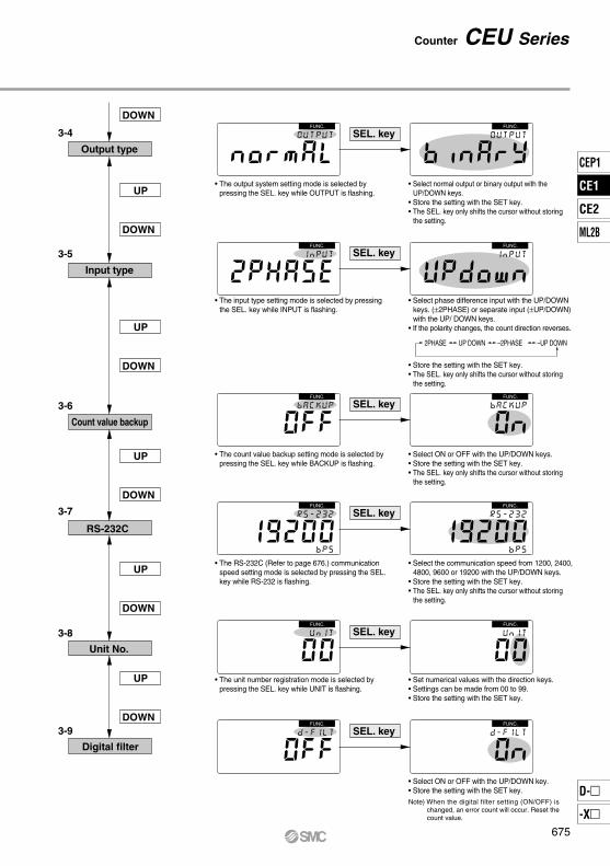
RS-232C
Unit No.
UP
DOWN
DOWN
UP
DOWN
UP
DOWN
UP
DOWN
Output type
3-4
3-5
Count value backup
3-6
3-7
3-8
SEL. keyFUNC. FUNC.
SEL. keyFUNC. FUNC.
SEL. keyFUNC. FUNC.
SEL. keyFUNC. FUNC.
SEL. keyFUNC. FUNC.
Input type
Digital filter
3-9
• Select ON or OFF with the UP/DOWN key.• Store the setting with the SET key.
SEL. keyFUNC. FUNC.
2PHASE UP DOWN –2PHASE –UP DOWN
Note) When the digital filter setting (ON/OFF) is changed, an error count will occur. Reset the count value.
UP
DOWN
• The output system setting mode is selected by pressing the SEL. key while OUTPUT is flashing.
• Select normal output or binary output with the UP/DOWN keys.
• Store the setting with the SET key.• The SEL. key only shifts the cursor without storing
the setting.
• The input type setting mode is selected by pressing the SEL. key while INPUT is flashing.
• Select phase difference input with the UP/DOWN keys. (±2PHASE) or separate input (±UP/DOWN) with the UP/ DOWN keys.
• If the polarity changes, the count direction reverses.
• Store the setting with the SET key.• The SEL. key only shifts the cursor without storing
the setting.
• The count value backup setting mode is selected by pressing the SEL. key while BACKUP is flashing.
• Select ON or OFF with the UP/DOWN keys.• Store the setting with the SET key.• The SEL. key only shifts the cursor without storing
the setting.
• The RS-232C (Refer to page 676.) communication speed setting mode is selected by pressing the SEL. key while RS-232 is flashing.
• Select the communication speed from 1200, 2400, 4800, 9600 or 19200 with the UP/DOWN keys.
• Store the setting with the SET key.• The SEL. key only shifts the cursor without storing
the setting.
• The unit number registration mode is selected by pressing the SEL. key while UNIT is flashing.
• Set numerical values with the direction keys.• Settings can be made from 00 to 99.• Store the setting with the SET key.
675
Counter CEU Series
CEP1
CE1
CE2
ML2B
D-
-X
CE1
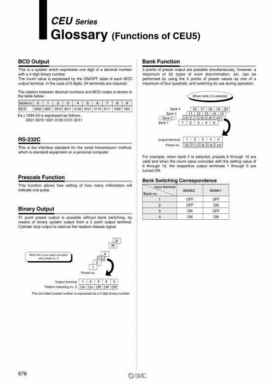
This is the interface standard for the serial transmission method, which is standard equipment on a personal computer.
31 point preset output is possible without bank switching, by means of binary system output from a 5 point output terminal. Cylinder stop output is used as the readout release signal.
5 points of preset output are possible simultaneously, however, a maximum of 20 types of work discrimination, etc. can be performed by using the 5 points of preset values as one of a maximum of four quadrats, and switching its use during operation.
For example, when bank 2 is selected, presets 6 through 10 are valid and when the count value coincides with the setting value of 6 through 10, the respective output terminals 1 through 5 are turned ON.
16 17 18 19 2011 12 13 14 15
6 7 8 9 10Bank 1
6 7 8 9 10
Bank 2Bank 3
Bank 4
When bank 2 is selected
On
1 2 3 4 5
On Off Off Off
3130
43
When the count value coincides with preset no. 3.
The relation between decimal numbers and BCD codes is shown in the table below.
Ex.) 1294.53 is expressed as follows.0001 0010 1001 0100 0101 0011
Decimal no.
BCD
0
0000
1
0001
2
0010
3
0011
4
0100
5
0101
6
0110
7
0111
8
1000
9
1001
Bank Switching Correspondence
Bank no.
1
2
3
4
OFF
OFF
ON
ON
OFF
ON
OFF
ON
Input terminalBANK2 BANK1
21
Preset no.
This function allows free setting of how many millimeters will indicate one pulse.
1
1 2 3 4 5
2 3 4 5
This is a system which expresses one digit of a decimal number with a 4 digit binary number.The count value is expressed by the ON/OFF state of each BCD output terminal. In the case of 6 digits, 24 terminals are required.
BCD Output
Prescale Function
RS-232C
Bank Function
Binary Output
CEU Series
Glossary (Functions of CEU5)
Output terminal
Pattern indicating no. 3
The coincident preset number is expressed as a 5 digit binary number.
Output terminal
Preset no.
676
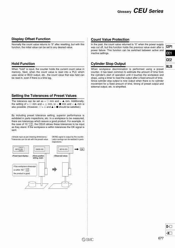
The tolerance can be set as + mm and − mm. Additionally, the setting of + mm and + mm, or − mm and − mm is also possible. (However, > and > should be satisfied.)
In the past, the count value returned to “0” when the power supply was cut off, but this function holds the previous value even after a power failure. This function can be switched between active and inactive settings.
When workpiece discrimination is performed using a preset counter, it has been common to estimate the amount of time from the cylinder's start of operation until it touches the workpiece and stops, using a timer to read the output after a fixed amount of time.Since cylinder stop output is now output when there is no cylinder movement for a fixed amount of time, timing of preset output and external output, etc. is simplified.
Normally the count value returns to “0” after resetting, but with this function, the initial value can be set to any desired value.
When “hold” is input, the counter holds the current count value in memory. Next, when the count value is read into a PLC which uses serial or BCD output, etc., the count value that was held can be read in, even if there is a time lag.
0000.000010.00+ 0000.05
– 0000.020010.03
<Simple input as per drawing dimensions>Tolerances can be set with the preset value.
OK/NG signal is output by the counter.Labor savings can be realized in parts inspections.
OK
<Observed value><Home positionsetting, reset>
<Preset input display>
Display Offset Function
Hold Function
Setting the Tolerances of Preset Values
Cylinder Stop Output
By including preset tolerance setting, superior performance is exhibited in parts inspections, etc. In a workpiece to be measured, there are tolerances which assure a good product. For example, in the case of 10 , the CEU5 allows these tolerances to be input as they stand. If the workpiece is within tolerances the OK signal is sent.
+ 0.05– 0.02
+ 0.05– 0.02
If the workpiece dimension
is within ,
the product is good.
10
677
Glossary CEU Series
Count Value Protection
CEP1
CE1
CE2
ML2B
D-
-X
CE1


![Unbenannt-1 - | Stepcraft · MID - Maximum infeed depth per cycle [mm] Revolution per minute of the HFS [1000x n/min.] Horizontal feed speed (X-/Y-direction) [mm/s] Vertical speed](https://img.pdfslide.us/doc/110x75/5b9fc66a09d3f2385c8c4480/unbenannt-1-stepcraft-mid-maximum-infeed-depth-per-cycle-mm-revolution.jpg)