Embed Size (px)
Citation preview

Centrifuge User Manual
Copyright 2017
C0336 C0336R

This manual was prepared with special care. LABNET INTERNATIONAL may change the manual at any time and without notice because of improvements, typographical errors, inaccuracies of current information or improvements
to facilities.
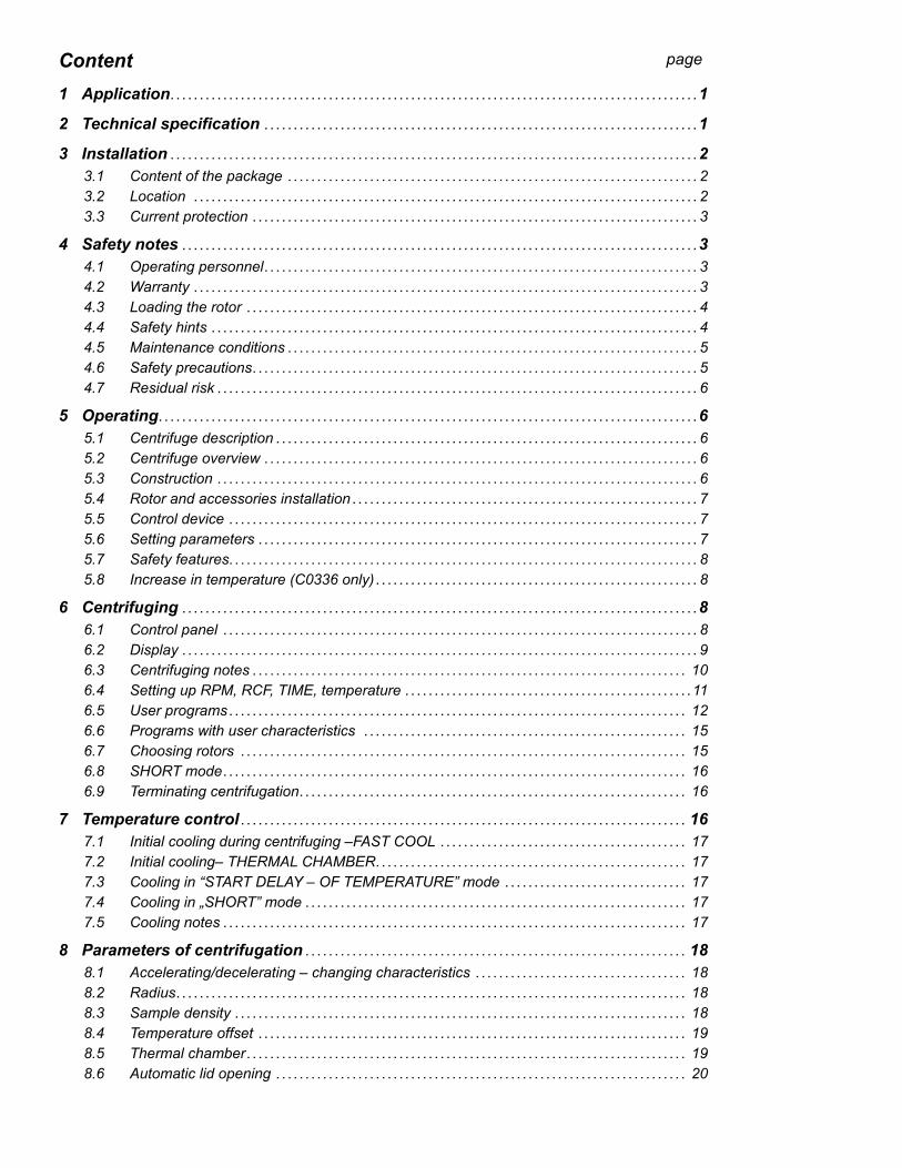
Content1 Application . . . . . . . . . . . . . . . . . . . . . . . . . . . . . . . . . . . . . . . . . . . . . . . . . . . . . . . . . . . . . . . . . . . . . . . . . . . . . . . . . . . . . . . . . .1
2 Technical specification . . . . . . . . . . . . . . . . . . . . . . . . . . . . . . . . . . . . . . . . . . . . . . . . . . . . . . . . . . . . . . . . . . . . . . . . . .1
3 Installation . . . . . . . . . . . . . . . . . . . . . . . . . . . . . . . . . . . . . . . . . . . . . . . . . . . . . . . . . . . . . . . . . . . . . . . . . . . . . . . . . . . . . . . . . .23.1 Content of the package . . . . . . . . . . . . . . . . . . . . . . . . . . . . . . . . . . . . . . . . . . . . . . . . . . . . . . . . . . . . . . . . . . . . . . 23.2 Location . . . . . . . . . . . . . . . . . . . . . . . . . . . . . . . . . . . . . . . . . . . . . . . . . . . . . . . . . . . . . . . . . . . . . . . . . . . . . . . . . . . . . . 23.3 Current protection . . . . . . . . . . . . . . . . . . . . . . . . . . . . . . . . . . . . . . . . . . . . . . . . . . . . . . . . . . . . . . . . . . . . . . . . . . . . 3
4 Safety notes . . . . . . . . . . . . . . . . . . . . . . . . . . . . . . . . . . . . . . . . . . . . . . . . . . . . . . . . . . . . . . . . . . . . . . . . . . . . . . . . . . . . . . . .34.1 Operating personnel . . . . . . . . . . . . . . . . . . . . . . . . . . . . . . . . . . . . . . . . . . . . . . . . . . . . . . . . . . . . . . . . . . . . . . . . . . 34.2 Warranty . . . . . . . . . . . . . . . . . . . . . . . . . . . . . . . . . . . . . . . . . . . . . . . . . . . . . . . . . . . . . . . . . . . . . . . . . . . . . . . . . . . . . . 34.3 Loading the rotor . . . . . . . . . . . . . . . . . . . . . . . . . . . . . . . . . . . . . . . . . . . . . . . . . . . . . . . . . . . . . . . . . . . . . . . . . . . . . 44.4 Safety hints . . . . . . . . . . . . . . . . . . . . . . . . . . . . . . . . . . . . . . . . . . . . . . . . . . . . . . . . . . . . . . . . . . . . . . . . . . . . . . . . . . . 44.5 Maintenance conditions . . . . . . . . . . . . . . . . . . . . . . . . . . . . . . . . . . . . . . . . . . . . . . . . . . . . . . . . . . . . . . . . . . . . . . 54.6 Safety precautions . . . . . . . . . . . . . . . . . . . . . . . . . . . . . . . . . . . . . . . . . . . . . . . . . . . . . . . . . . . . . . . . . . . . . . . . . . . . 54.7 Residual risk . . . . . . . . . . . . . . . . . . . . . . . . . . . . . . . . . . . . . . . . . . . . . . . . . . . . . . . . . . . . . . . . . . . . . . . . . . . . . . . . . . 6
5 Operating . . . . . . . . . . . . . . . . . . . . . . . . . . . . . . . . . . . . . . . . . . . . . . . . . . . . . . . . . . . . . . . . . . . . . . . . . . . . . . . . . . . . . . . . . . . .65.1 Centrifuge description . . . . . . . . . . . . . . . . . . . . . . . . . . . . . . . . . . . . . . . . . . . . . . . . . . . . . . . . . . . . . . . . . . . . . . . . 65.2 Centrifuge overview . . . . . . . . . . . . . . . . . . . . . . . . . . . . . . . . . . . . . . . . . . . . . . . . . . . . . . . . . . . . . . . . . . . . . . . . . . 65.3 Construction . . . . . . . . . . . . . . . . . . . . . . . . . . . . . . . . . . . . . . . . . . . . . . . . . . . . . . . . . . . . . . . . . . . . . . . . . . . . . . . . . . 65.4 Rotor and accessories installation . . . . . . . . . . . . . . . . . . . . . . . . . . . . . . . . . . . . . . . . . . . . . . . . . . . . . . . . . . . 75.5 Control device . . . . . . . . . . . . . . . . . . . . . . . . . . . . . . . . . . . . . . . . . . . . . . . . . . . . . . . . . . . . . . . . . . . . . . . . . . . . . . . . 75.6 Setting parameters . . . . . . . . . . . . . . . . . . . . . . . . . . . . . . . . . . . . . . . . . . . . . . . . . . . . . . . . . . . . . . . . . . . . . . . . . . . 75.7 Safety features. . . . . . . . . . . . . . . . . . . . . . . . . . . . . . . . . . . . . . . . . . . . . . . . . . . . . . . . . . . . . . . . . . . . . . . . . . . . . . . . 85.8 Increase in temperature (C0336 only) . . . . . . . . . . . . . . . . . . . . . . . . . . . . . . . . . . . . . . . . . . . . . . . . . . . . . . . 8
6 Centrifuging . . . . . . . . . . . . . . . . . . . . . . . . . . . . . . . . . . . . . . . . . . . . . . . . . . . . . . . . . . . . . . . . . . . . . . . . . . . . . . . . . . . . . . . .86.1 Control panel . . . . . . . . . . . . . . . . . . . . . . . . . . . . . . . . . . . . . . . . . . . . . . . . . . . . . . . . . . . . . . . . . . . . . . . . . . . . . . . . . 86.2 Display . . . . . . . . . . . . . . . . . . . . . . . . . . . . . . . . . . . . . . . . . . . . . . . . . . . . . . . . . . . . . . . . . . . . . . . . . . . . . . . . . . . . . . . . 96.3 Centrifuging notes . . . . . . . . . . . . . . . . . . . . . . . . . . . . . . . . . . . . . . . . . . . . . . . . . . . . . . . . . . . . . . . . . . . . . . . . . . 106.4 Setting up RPM, RCF, TIME, temperature . . . . . . . . . . . . . . . . . . . . . . . . . . . . . . . . . . . . . . . . . . . . . . . . .116.5 User programs . . . . . . . . . . . . . . . . . . . . . . . . . . . . . . . . . . . . . . . . . . . . . . . . . . . . . . . . . . . . . . . . . . . . . . . . . . . . . . 126.6 Programs with user characteristics . . . . . . . . . . . . . . . . . . . . . . . . . . . . . . . . . . . . . . . . . . . . . . . . . . . . . . . 156.7 Choosing rotors . . . . . . . . . . . . . . . . . . . . . . . . . . . . . . . . . . . . . . . . . . . . . . . . . . . . . . . . . . . . . . . . . . . . . . . . . . . . 156.8 SHORT mode . . . . . . . . . . . . . . . . . . . . . . . . . . . . . . . . . . . . . . . . . . . . . . . . . . . . . . . . . . . . . . . . . . . . . . . . . . . . . . . 166.9 Terminating centrifugation . . . . . . . . . . . . . . . . . . . . . . . . . . . . . . . . . . . . . . . . . . . . . . . . . . . . . . . . . . . . . . . . . . 16
7 Temperature control . . . . . . . . . . . . . . . . . . . . . . . . . . . . . . . . . . . . . . . . . . . . . . . . . . . . . . . . . . . . . . . . . . . . . . . . . . . . 167.1 Initial cooling during centrifuging –FAST COOL . . . . . . . . . . . . . . . . . . . . . . . . . . . . . . . . . . . . . . . . . . 177.2 Initial cooling– THERMAL CHAMBER . . . . . . . . . . . . . . . . . . . . . . . . . . . . . . . . . . . . . . . . . . . . . . . . . . . . . 177.3 Cooling in “START DELAY – OF TEMPERATURE” mode . . . . . . . . . . . . . . . . . . . . . . . . . . . . . . . 177.4 Cooling in „SHORT” mode . . . . . . . . . . . . . . . . . . . . . . . . . . . . . . . . . . . . . . . . . . . . . . . . . . . . . . . . . . . . . . . . . 177.5 Cooling notes . . . . . . . . . . . . . . . . . . . . . . . . . . . . . . . . . . . . . . . . . . . . . . . . . . . . . . . . . . . . . . . . . . . . . . . . . . . . . . . 17
8 Parameters of centrifugation . . . . . . . . . . . . . . . . . . . . . . . . . . . . . . . . . . . . . . . . . . . . . . . . . . . . . . . . . . . . . . . . . 188.1 Accelerating/decelerating – changing characteristics . . . . . . . . . . . . . . . . . . . . . . . . . . . . . . . . . . . . 188.2 Radius . . . . . . . . . . . . . . . . . . . . . . . . . . . . . . . . . . . . . . . . . . . . . . . . . . . . . . . . . . . . . . . . . . . . . . . . . . . . . . . . . . . . . . . 188.3 Sample density . . . . . . . . . . . . . . . . . . . . . . . . . . . . . . . . . . . . . . . . . . . . . . . . . . . . . . . . . . . . . . . . . . . . . . . . . . . . . 188.4 Temperature offset . . . . . . . . . . . . . . . . . . . . . . . . . . . . . . . . . . . . . . . . . . . . . . . . . . . . . . . . . . . . . . . . . . . . . . . . . 198.5 Thermal chamber . . . . . . . . . . . . . . . . . . . . . . . . . . . . . . . . . . . . . . . . . . . . . . . . . . . . . . . . . . . . . . . . . . . . . . . . . . . 198.6 Automatic lid opening . . . . . . . . . . . . . . . . . . . . . . . . . . . . . . . . . . . . . . . . . . . . . . . . . . . . . . . . . . . . . . . . . . . . . . 20
page

8.7 Start delay - of time . . . . . . . . . . . . . . . . . . . . . . . . . . . . . . . . . . . . . . . . . . . . . . . . . . . . . . . . . . . . . . . . . . . . . . . . . 208.8 Start delay – of temperature . . . . . . . . . . . . . . . . . . . . . . . . . . . . . . . . . . . . . . . . . . . . . . . . . . . . . . . . . . . . . . . 208.9 Errors . . . . . . . . . . . . . . . . . . . . . . . . . . . . . . . . . . . . . . . . . . . . . . . . . . . . . . . . . . . . . . . . . . . . . . . . . . . . . . . . . . . . . . . . 218.10 Temporarily disabled functions . . . . . . . . . . . . . . . . . . . . . . . . . . . . . . . . . . . . . . . . . . . . . . . . . . . . . . . . . . . . . 228.11 Unbalance . . . . . . . . . . . . . . . . . . . . . . . . . . . . . . . . . . . . . . . . . . . . . . . . . . . . . . . . . . . . . . . . . . . . . . . . . . . . . . . . . . 228.12 Screen saver . . . . . . . . . . . . . . . . . . . . . . . . . . . . . . . . . . . . . . . . . . . . . . . . . . . . . . . . . . . . . . . . . . . . . . . . . . . . . . . . 238.13 Visual alarm . . . . . . . . . . . . . . . . . . . . . . . . . . . . . . . . . . . . . . . . . . . . . . . . . . . . . . . . . . . . . . . . . . . . . . . . . . . . . . . . . 238.14 Types of main screen . . . . . . . . . . . . . . . . . . . . . . . . . . . . . . . . . . . . . . . . . . . . . . . . . . . . . . . . . . . . . . . . . . . . . . . 238.14.1 Switching the basic display to simplified screen . . . . . . . . . . . . . . . . . . . . . . . . . . . . . . . . . . . . . . . . . . 238.14.2 Switching the simplified screen to basic display . . . . . . . . . . . . . . . . . . . . . . . . . . . . . . . . . . . . . . . . . . 238.15 Rotating time . . . . . . . . . . . . . . . . . . . . . . . . . . . . . . . . . . . . . . . . . . . . . . . . . . . . . . . . . . . . . . . . . . . . . . . . . . . . . . . . 248.16 Sounds . . . . . . . . . . . . . . . . . . . . . . . . . . . . . . . . . . . . . . . . . . . . . . . . . . . . . . . . . . . . . . . . . . . . . . . . . . . . . . . . . . . . . . 248.17 Time/date . . . . . . . . . . . . . . . . . . . . . . . . . . . . . . . . . . . . . . . . . . . . . . . . . . . . . . . . . . . . . . . . . . . . . . . . . . . . . . . . . . . 248.18 Language choosing . . . . . . . . . . . . . . . . . . . . . . . . . . . . . . . . . . . . . . . . . . . . . . . . . . . . . . . . . . . . . . . . . . . . . . . . 258.19 Other . . . . . . . . . . . . . . . . . . . . . . . . . . . . . . . . . . . . . . . . . . . . . . . . . . . . . . . . . . . . . . . . . . . . . . . . . . . . . . . . . . . . . . . . 258.20 Password protection . . . . . . . . . . . . . . . . . . . . . . . . . . . . . . . . . . . . . . . . . . . . . . . . . . . . . . . . . . . . . . . . . . . . . . . . 268.21 Total work time . . . . . . . . . . . . . . . . . . . . . . . . . . . . . . . . . . . . . . . . . . . . . . . . . . . . . . . . . . . . . . . . . . . . . . . . . . . . . 278.22 Diagnostics . . . . . . . . . . . . . . . . . . . . . . . . . . . . . . . . . . . . . . . . . . . . . . . . . . . . . . . . . . . . . . . . . . . . . . . . . . . . . . . . . 278.23 Factory settings . . . . . . . . . . . . . . . . . . . . . . . . . . . . . . . . . . . . . . . . . . . . . . . . . . . . . . . . . . . . . . . . . . . . . . . . . . . . 278.24 Rotor runtime . . . . . . . . . . . . . . . . . . . . . . . . . . . . . . . . . . . . . . . . . . . . . . . . . . . . . . . . . . . . . . . . . . . . . . . . . . . . . . 278.25 Cycles history . . . . . . . . . . . . . . . . . . . . . . . . . . . . . . . . . . . . . . . . . . . . . . . . . . . . . . . . . . . . . . . . . . . . . . . . . . . . . . 278.26 Manufacturer’s details . . . . . . . . . . . . . . . . . . . . . . . . . . . . . . . . . . . . . . . . . . . . . . . . . . . . . . . . . . . . . . . . . . . . . 27
9 Maintenance . . . . . . . . . . . . . . . . . . . . . . . . . . . . . . . . . . . . . . . . . . . . . . . . . . . . . . . . . . . . . . . . . . . . . . . . . . . . . . . . . . . . . . 289.1 Cleaning of the centrifuge . . . . . . . . . . . . . . . . . . . . . . . . . . . . . . . . . . . . . . . . . . . . . . . . . . . . . . . . . . . . . . . . . . 289.2 Maintenance of centrifuge elements . . . . . . . . . . . . . . . . . . . . . . . . . . . . . . . . . . . . . . . . . . . . . . . . . . . . . . . 289.3 Sterilization . . . . . . . . . . . . . . . . . . . . . . . . . . . . . . . . . . . . . . . . . . . . . . . . . . . . . . . . . . . . . . . . . . . . . . . . . . . . . . . . . 299.3.1 Autoclaving . . . . . . . . . . . . . . . . . . . . . . . . . . . . . . . . . . . . . . . . . . . . . . . . . . . . . . . . . . . . . . . . . . . . . . . . . . . . . . . . . 299.4 Chemical resistance . . . . . . . . . . . . . . . . . . . . . . . . . . . . . . . . . . . . . . . . . . . . . . . . . . . . . . . . . . . . . . . . . . . . . . . . 30
10 Troubleshooting . . . . . . . . . . . . . . . . . . . . . . . . . . . . . . . . . . . . . . . . . . . . . . . . . . . . . . . . . . . . . . . . . . . . . . . . . . . . . . . . . 3110.1 Emergency cover release . . . . . . . . . . . . . . . . . . . . . . . . . . . . . . . . . . . . . . . . . . . . . . . . . . . . . . . . . . . . . . . . . . 32
Appendix A Equipment Disposal - European Regulations . . . . . . . . . . . . . . . . . . . . . . . . . . . . . . . . . . . . . . . . . . . . . . . . 32
Symbols and Conventions . . . . . . . . . . . . . . . . . . . . . . . . . . . . . . . . . . . . . . . . . . . . . . . . . . . . . . . . . . . . . . . . . . . . . . . . 32
Limited Warranty . . . . . . . . . . . . . . . . . . . . . . . . . . . . . . . . . . . . . . . . . . . . . . . . . . . . . . . . . . . . . . . . . . . . . . . . . . . . . . . . . . . . 33
NOMOGRAM . . . . . . . . . . . . . . . . . . . . . . . . . . . . . . . . . . . . . . . . . . . . . . . . . . . . . . . . . . . . . . . . . . . . . . . . . . . . . . . . . . . . . . . . . 34

Centrifuge user manual | 1
1 ApplicationCentrifuges are used for separation samples taken from people’s, animal’s and plant’s components of different densi-ties, under the influence of the centrifugal force, to provide information about their biological state (C0336 – ventilated, C0336R– with cooling).Its construction ensures easy operation, safe work and wide range of applications at laboratories engaged in routine medical analyses, biochemical research works etc.This centrifuge is not biotight and therefore during centrifugation of preparations requiring biotightness one has to use closed and sealed containers and rotors. In the centrifuge, it is prohibited to centrifuge caustic, inflammable and explosive preparations.
2 Technical specificationmanufacturer LABNET INTERNATIONALtype C0336 C0336Rmains voltage (L1+N+PE) 230V 120V 230V 120V
10% ±5% 10% ±5%mains frequency 50/60Hz 50Hz 60Hz 60Hzconnected load (max.) 250W 600Wovercurrent protection T 4A T 10Acooling medium - R507 (CFC/HCFC free)capacity (max.) 500 mlspeed – RPM 90 * 18000 rpm (step 1 rpm)force – RCF 24270 x g (step 1 x g)kinetic energy (max.) 8800 Nmrunning time 00:00:01 ÷ 99:59:59 – [hours, min., sec] (step 1s)time counting since start button is pressed / since preselected speed is reachedshort-time operation mode – SHORT yes continuous operation mode – HOLD yesuser programs 100adjustable temperature - -20 ÷ 40*C* (step 1°C)initial cooling (Fast Cool) no yesguaranteed temperature with max. rotor speed - ≤4*C
cooling/heating without centrifuging no/no yes/nocooling/heating with centrifuging no/no yes/noacceleration (ACEL) 10 linear curvesdeceleration (DECEL) 10 linear curvesprogrammable non-linear curves:acceleration 10deceleration 10USB communication yesElectromagnetic compatibility according to EN 61326-2-6:2006ambient conditions PN-EN 61010-1 p.1.4.1set-up site indoors onlyambient temperature 2° ÷ 40*Chumidity (maximum relative humidity) < 80%excess-voltage category II EN 61010-1pollution degree 2 EN 61010-1safety area 300 mm

2 | Centrifuge user manual
Degree of protection: (according to PN-IEC 34-5) IP 21 IP 20
dimensions: height (H) 320 mmwidth (W) 365 mmdepth (D) 495 mm 660 mmwith open cover (Hoc) 665 mmnoise level 56 dBweight 230V 28 kg 47 kgweight 120V 29,5 kg 50,7 kg
* time and possibility of obtaining a set temperature is dependent on multiple factors, including: rotor type, established RPM, ambient temperature; accuracy: - ±1*C appropriate for place of temperature sensor.
Menu languages: POLISH, ENGLISH, GERMAN, SPANISH, ITALIAN, PORTUGUESE, RUSSIAN, SWEDISH, FRENCH (without national characters).
3 InstallationOpen the package. Remove the box containing the accessories. Take out centrifuge from the container. Keep the box and packing materials in case of service shipping.
3.1 Content of the package name qty (pcs.)centrifuge C0336 1complete clamp 1spanner for the rotor 1emergency opening of the coverpower cord 230V / 120V 1Fuse WTA T 4A 250V / WTA T10A 250V 2petroleum jelly 20ml 1USB A-A cable 1user manual 1
3.2 Location • The device is heavy, so lifting and carrying the centrifuge can lead to back injuries. Risk of injury
while lifting and carrying heavy loads.• Lifting and transporting of the centrifuge should be done with a sufficient number of helpers. Use
a transport aid for transporting the centrifuge.• The device should be lifted by the underside in the vicinity of the its feet and placed directly on
a suitable lab table.

Centrifuge user manual | 3
• Ensure safe location.• The centrifuge shall not be located near source of heat and shall not be subjected to direct sunlight.• Centrifuge should be flat-leveled. Effect of leveling shall be ensured by stable and flat-leveled table
top for the centrifuge.• Centrifuge should be set horizontally on a rigid base.• It is necessary to ensure a ventilation zone of the minimum 30cm round the centrifuge from every
direction. Do not veil ventilation holes!• Table for centrifuge should possess safety zone of the minimum 30cm round the centrifuge from
every direction (safety needs in case of malfunction according to EN 61010-020.• Table for centrifuge should be free of contaminants before locating of centrifuge.• Passed parameters of the centrifuge are referring to the above named temperatures (see 2. Technical
specification). • At the change of the place from cold to warm one, condensation of water will occur inside the cen-
trifuge. It is important then that sufficient time be provided for drying the centrifuge prior to starting the centrifuge again (min. 4 hours).
• Do not position the centrifuge so that it is difficult to operate the power switch• Supply voltage given on the rating plate has to be consistent with local supply voltage. LABNET
INTERNATIONAL laboratory centrifuges are 1st safety class devices and they are provided with the three-core cable with the plug resistant to dynamic loadings. Mains socket shall be provided with the safety pin.
• It is recommended to install emergency cut-out that shall be located far from the centrifuge, near the exit or beyond the room.
• Before switching on, check whether the centrifuge is connected to power supply correctly. It is obligatory to use only power cord recommended by manufacturer.
• Before using check whether the device is correctly installed.
3.3 Current protectionThe centrifuge is equipped with thermal current protection. Fuse is situated in the plug-in socket unit at back wall of the centrifuge.
4 Safety notes
4.1 Operating personnel• Laboratory centrifuge can be operated by laboratory personnel after getting acquainted with user
manual.• User manual shall be always held near the centrifuge.• The centrifuge cannot be misused.• If the centrifuge is used in a manner not specified by the manufacturer, the protection provided by
the device may be impaired.
4.2 Warranty • Warranty period amounts to minimum 24 months (unless otherwise specified in the purchase docu-
ments). • The service life of the centrifuge specified by the manufacturer amounts to 10 years.• Manufacturer reserves the right to make technical changes in manufactured products.• Maximum period of storage of not used centrifuge amounts to 1 year. After this period, a service
authorized by manufacturer should carry out technical inspection of the centrifuge.

4 | Centrifuge user manual
4.3 Loading the rotor• Laboratory centrifuge can be operated by laboratory personnel after getting acquainted with user
manual.• User manual shall be always held near the centrifuge.• The centrifuge cannot be misused.
CORRECT
CORRECT
WRONG
WRONG• It is necessary to insert test tubes symmetrically on the opposite sides.FILLING TUBES• Fill test tubes outside the centrifuge.• Please pay special attention to the quality and proper thickness of the glass test tubes walls. Those
shall be test tubes for centrifuges.• Fill test tubes outside the centrifuge.
4.4 Safety hintsROTORS MAINTENANCE• Lubricate the swing-out rotor journal pins.• Use only accessories in good condition.• Protect equipment against corrosion using accurate preventive maintenance.HS ACCESSORIES MAINTENANCE• HS accessories maintenance.• Make sure that rubber O-rings are lightly coated with silicone grease. HAZARDOUS MATERIALS• Accessories are not biotight. For centrifuging infectious materials, it is necessary to use hermetically
closed tubes meeting demands of biotightness, in order to prevent germs migration into the centrifuge and beyond it.
• It is not allowed to subject to centrifugation toxic materials with damaged leak proof seals of the rotor or test-tube. Proper disinfection procedures have to be carried out when dangerous substances contaminated the centrifuge or its accessories.

Centrifuge user manual | 5
EXPLOSIVE AND COMBUSTIBLE MATERIALS• It is not allowed to centrifuge explosive and inflammable materials.• It is not allowed to centrifuge substances prone to reacting in result of supplying high energy during
centrifugation. The centrifuge cannot be operated in explosion-endangered areas• It is not allowed to centrifuge materials capable of generating inflammable or explosive mixtures
when subjected to air.
4.5 Maintenance conditionsSTART-UP• Prior to switching the centrifuge on, one shall read carefully all sections of this instruction in order to
ensure smooth operation and avoid damages of this device or its accessories.• In order to protect the centrifuge against unbalance, fill in the test tubes up to the same weight.TRANSPORTATION• Centrifuge must not be transported with the rotor mounted on the shaft.GENERAL HINTS• One must use original rotors, test-tubes and spare parts only.• In case of faulty operation of the centrifuge one shall ask for assistance of service of LABNET
INTERNATIONAL company or its authorized representatives.• It is not allowed to switch the centrifuge on if it is not installed properly or rotor is not fitted correctly.CENTRIFUGES SUBSTANCES• It isn’t allowed to exceed load limit set by the manufacturer. Rotors are intended for fluids of average
homogeneous density equal to 1,2 g/cm3 or smaller when centrifugation is carried out at maximum speed. When fluids of higher density shall be used, then it is necessary to change density of centrifuges sample in PARAM/DENSITY field.
4.6 Safety precautionsFor safety reasons, inspections of the centrifuge carried out by the authorized service at least once a year after the period of warranty. The reason for more frequent inspections could be corrosion inducing environment. Examina-tions should end with issuing report of validation that checks on the technical state of the laboratory centrifuge. It is being recommended to establish document where every repairs and reviews are being registered. Both these documents should be stored in the place of use of the centrifuge.
INSPECTION PROCEDURES CARRIED OUT BY THE OPERATOROperator has to pay special attention to the fact that the centrifuge parts of key importance due to safety reasons are not damaged. This remark is specifically important as for:• Centrifuge accessories and especially structural changes, corrosion, preliminary cracks, abrasion
of metal parts.• Screw joints. • Inspection of the rotor assembly. • Inspection of bioseals of the buckets if such are used. • Control of execution of the guarantee yearly technical inspection of the centrifugeOnly the manufacturer-specified holders, included in the equipment list, as well as centrifuge capillar-ies, which diameter, length and durability are suitable, should be used for spinning in this centrifuge. The use of equipment made by other manufacturers should be consulted with the manufacturer of the centrifuge. • It is not allowed to lift or shift the centrifuge during operation, and rest on it.• It is not allowed to stay in the safety zone within 30 cm distance around the centrifuge neither leave
within this zone some things, e.g. glass vessels.• It is not allowed to put any objects on the centrifuge.COVER OPENING• It isn’t allowed to open the cover manually in emergency procedure when rotor is still turning.

6 | Centrifuge user manual
ROTORS• It is not allowed to use the rotors and round carriers with signs of corrosion or other mechanical
defects.• It is not allowed to centrifuge highly corrosive substances which may cause material impairment and
lower mechanical properties of rotor and round carriers.• It isn’t allowed to use rotors and accessories not admitted by the manufacturer. Let to use commercial
glass and plastic test tubes, which are destined to centrifuging in this laboratory centrifuge. Oneshould absolutely not use poor quality elements. Cracking of glass vessels and test tubes couldresult in dangerous vibration of the centrifuge.
• It is not allowed to carry out centrifugation with the rotor caps taken off or not driven tight.
4.7 Residual riskThe centrifuge is built according to the state-of-the-art and the recognized safety regulations. Nevertheless, still remain some level of residual risk due to improper operation and malfunctions. It is possible to decrease residual risk by strictly applying user manual conditions and correcting malfunction which could threaten safety, immediately.
5 Operating
5.1 Centrifuge descriptionNew generation of LABNET INTERNATIONAL laboratory centrifuges is provided with state-of-the-art micropro-cessor control systems, very durable and quiet asynchronous brushless motors and accessories consistent with requirements of the present-day user.
5.2 Centrifuge overview
Fig.2. Right side of centrifuge
Fig.1. General view
6
5
4
3
2
1
1. Power switch2. USB3. Control panel4. Point of emergency lid opening5. Lid6. Inspection glass
Fig.3. Assembly of angle rotor
1. Motor axle2. Rotor3. Rotor lid4. Complete clamp
4
2
3
1
21
Fig.4. Mains socket back of the centrifuge
1. Main socket2. Fuse socket
5.3 Construction The centrifuge has rigid self-supporting structure. Housing was made of sheet aluminum, back made of steel sheet. Front and cover was made of ABS type plastic. Cover is fixed on steel axles of hinges and from the front it

Centrifuge user manual | 7
is locked with two electromagnetic locks blocking possible opening during centrifugation. Rotation chamber casing was made of thick steel sheet. The rotation chamber bowl is made of stainless steel sheet. Rotors and containers are from aluminum, lids from polycarbonate and reductive inserts from the polypropylene.
5.4 Rotor and accessories installation• Connect the centrifuge to the mains (master switch on the back side of the centrifuge).• Turn on the centrifuge (button on the side of the centrifuge). • Open the cover of the centrifuge by pressing the COVER key (see section Centrifuging/Control Panel). Prior
to putting the rotor in, one has to check if the rotating chamber is free of impurities, e.g., such as dust, glass splinters, residues of fluids that must be taken away.
• One shall fit the rotor on the motor shaft driving it home on the cone.• Screw-in the bolt for fixing the rotor (clockwise) and screw it tightly home with the supplied spanner for the rotor. • Swing-out rotors have to be provided with the buckets in all seats. One should remember that every buckets
swings individually. Bucket suspension studs should be lubricated periodically with petroleum jelly. • In case of rotors designed with the cover they must not be used without it. Rotor covers must be closed exactly.
Rotor covers ensure smaller drags of the rotors, proper setting of the test-tubes and airtight sealing. • One should use only buckets intended for selected types of the rotor.• Fill test tubes outside the centrifuge. • In case of centrifuging in an angle rotor, test tubes (buckets) have to be filled properly in order to prevent from
pouring fluids during centrifuging.
Tubes must be filled so that the material does not escape from the reservoir during centrifugation.
liquid
centrifugal force
One shall fill tubes according to formula:Max liquid level < Tube height – Internal tube diameter/2Internal tube diameter
Max
liqu
id le
vel
Tube
hei
ght
Observe the manufacturer’s restrictions about the filling of the test tube.
It is recommended to equalize vessels loads as much as possible in order to ensure minimal vibrations during operation.
• In order to prolong lifetime of the rotor and gaskets rotors shall be lubricated with the maintenance oil, while gaskets and threaded parts shall be lubricated with the petroleum jelly.
• For replacement of the rotor one shall unscrew clamping and then grab the rotor with both hands at opposite sides, taking it away from drive shaft by pulling it up.
5.5 Control deviceThe microprocessor control unit of the centrifuge ensures broad possibilities of providing, realization and reading of work parameters.
5.6 Setting parametersData setting and read-out system forms hermetically closed keyboard with distinctly accessible operation points. Easily readable displays signaling individual performed operations facilitate operator’s programming and recording of parameters and condition of the centrifuge. The centrifuge is provided with the USB interface that enables connection of the centrifuge to external PC unit with the printer and recording the centrifugation parameters.

8 | Centrifuge user manual
5.7 Safety featuresCover lockThe centrifuge can be started only with properly closed cover. While, the cover can be opened only after stop-ping the rotor. In case of emergency opening of the cover during operation, the centrifuge will be immediately switched-off and the rotor will brake till complete stopping.Unbalance detectingWhen loads of opposite buckets or carriers in rotors are unbalanced, the drive will be switched-off during accelera-tion or operation of the centrifuge – and the error message will be displayed.Rotor verification and checking compatibility with loaded programDirectly after starting centrifuging, a unit verifies the type of the rotor applied and in the case of its incompatibility with the type indicated in the application or absence of the rotor, the spinning process shall be stopped with simultaneous displaying the error message. The conformity of the type of the rotor is signaled with a single audible signal. In case auto identification (see 9.8 Other) option is checked, proper rotor will be automatically chosen, without user engagement. Rest state inspectionOpening of the centrifuge’s cover is possible only with the rotor in the state of rest. When the rotor is being stopped, the STOP diode is on and goes off when it is stopped. (Excepting emergency cover opening) – see p. TROUBLESHOOTING.Checking of excessive temperatureIf temperature in rotation chamber exceeds 50°C (C0336) / 65°C (C0336R) caused by, for example, malfunction of cooling system, drive will be switched off and error message will be displayed. The reboot is only possible after chilling device.
5.8 Increase in temperature (C0336 only)In uncooled centrifuges, the temperature in the rotor chamber, rotor and sample can increase to above 40°C, based on the run time, g-force (RCF)/speed and ambient temperature.
6 CentrifugingPower switching ON/OFF is carried out with master switch situated on the side wall of the centrifuge. All settings on the centrifuge are done by means of the control panel.
6.1 Control panelThe control panel placed on the front casing serves the purpose of controlling centrifuge operation.

Centrifuge user manual | 9
Control panel► ► SHORT1 short-time centrifuging► START start centrifugation run
STOP2 end centrifugation run
COVER cover opening
FAST COOL start fast cooling mode
BACK RPM/RCF
exit the current menu / cancelling switching between rpm display mode and rcf display mode
▲ UP navigation in menu / increasing values▼ DOWN navigation in menu / decreasing values◄ LEFT navigation in menu► RIGHT navigation in menu
SET SET changing parameters / confirming changes1 the centrifuge is working as long as the key is pressed2 first-time pressing press – will make stopping centrifuging with acceleration characteristics set in the current
program (confirm message with pressing STOP or BACK key), second-time pressing – will make the centrifuging as fast as possible (quickest characteristic). During setting of the parameters, it serves for exiting zones on the primary screen without introducing changes.
6.2 DisplayThe display is located in the centre of the control panel. The main screen variants are presented below.MAIN SCREEN
C0336
C0336R
SPEED rotor speed assigned/measuredRCF centrifugal force assigned/measuredTIME centrifuging time assigned/measuredTEMP temperature assigned/measured
PROG –– program no.11199 / ––––– rotor no.
PARAM parameters of the centrifugeMENU configuration menu
changing values user acc/dec curves (ACC/DEC 10-19)
density > 1,2 g/cm3
counting time down (decreasing) counting time up (increasing)
Cooling to the desired temperature

10 | Centrifuge user manual
centrifuging centrifuging (with automatic cover opening)
rotor stopped / closed cover rotor stopped / opened lid
stopping rotor fastest decelerating
identifying rotor
thermal chamber
temperature delay
time delay
drop-down list
temporarily disabled
locked
time counting (blinking)
disabled option active option
6.3 Centrifuging notes• Connect the centrifuge to the mains (master switch on left side of the centrifuge).• Open the cover of the centrifuge by pressing the COVER key. Prior to putting the rotor in, one has to check if
the rotating chamber is free of impurities, e.g. such as dust, glass splinters, residues of fluids that must be taken away.
• One shall fit the rotor on the motor shaft driving it home on the cone.
Fitting the rotor too shallow will result in lack of identification of the rotor after start of the centrifuge, displaying the error message and stopping the centrifuge.
• Screw-in the bolt for fixing the rotor (clockwise) and screw it tightly home with the supplied spanner for the rotor. • Swing-out rotors have to be provided with the buckets in all seats. One should remember that every buckets
swings individually. Bucket suspension studs should be lubricated periodically with petroleum jelly. • In case of rotors designed with the cover they must not be used without it. Rotor covers must be closed exactly.
Rotor covers ensure smaller drags of the rotors, proper setting of the test-tubes and airtight sealing. • One should use only buckets intended for selected types of the rotor.• Fill test tubes outside the centrifuge. • Put on or screw the caps on vessels and rotors (if applicable). • In case of centrifuging in an angle rotor, test tubes (buckets) have to be filled properly in order to avoid overflows.
Centrifuge will tolerate small weight differences occurring during loading of rotors. However, it is recommended to equalize vessels loads as much as possible in order to ensure minimal vibrations during operation. When the centrifuge is started with large imbalance, the unbalance control system will switch-off the drive system and error signal will be transmitted. On the monitoring panel, error message will be displayed.
• In order to prolong lifetime of the gaskets and threaded parts shall be lubricated with the petroleum jelly • For replacement of the rotor one shall unscrew clamping and then grab the rotor with both hands at opposite
sides, taking it away from drive shaft by pulling it up.

Centrifuge user manual | 11
6.4 Setting up RPM, RCF, TIME, temperatureOn the main screen, it is possible to set:rotating speed - RPM SPEED relative centrifugal force RCFcentrifuging time TIMEcentrifuging temperature TEMP (R only)
Exemplary change of SPEED setting:
• Press SET (to enter edit mode).• With ▲▼◄► keys mark SPEED fold (blinking).
• Press SET.• Choose demanded order of magnitude
by pressing ◄►, e.g.: 926 (9 - blinking).• Set demanded value by pressing ▲▼.• Repeat above two steps for other orders of magnitude. • Confirm set value by pressing SET.• Leave edit mode by pressing BACK.
Exemplary change of RCF setting:
• Press SET (to enter edit mode).• With ▲▼◄► keys mark RCF fold (blinking).
• Press SET.• Choose demanded order of magnitude
by pressing ◄►, e.g.: 926 (9 - blinking).• Set demanded value by pressing ▲▼.• Repeat above two steps for other orders of magnitude. • Confirm set value by pressing SET.• Leave edit mode by pressing BACK.
Exemplary change of TIME setting:
• Press SET (to enter edit mode).• With ▲▼◄► keys mark TIME fold (blinking).
• Press SET.• Choose demanded order of magnitude
by pressing ◄►, e.g.: 13:18:00 (1 - blinking).• Set demanded value by pressing ▲▼.• Repeat above two steps for other orders of magnitude. • Confirm set value by pressing SET.• Leave edit mode by pressing BACK.

12 | Centrifuge user manual
Exemplary change of TEMP setting:
• Press SET (to enter edit mode).• With ▲▼◄► keys mark TEMP fold (blinking).
• Press SET.• Set demanded value by pressing ▲▼.• Confirm set value by pressing SET.• Leave edit mode by pressing BACK.
Changing parameters during run
There is a possibility to change parameters: SPEED, RCF, TIME, TEMP during centrifuging. Such modifications give in currently running program. Modification during run is repre-sented by PROG –– symbol.
Detailed description of setting values (e.g. TIME).
• Press SET (to enter edit mode).• With ▲▼◄► keys mark TIME fold (blinking).
0 0 : 0 2 : 11[hh : mm : ss]
e.g.:• centrifuging time – 2 minutes 11 seconds
• Press SET.• Choose “hours”, “minutes” or “seconds” by pressing ◄►, e.g.:
00:07:00 (00 - blinking).• Set demanded value by pressing ▲▼.• Repeat above two steps to set demanded time. • Confirm set value by pressing SET.• Leave edit mode by pressing BACK.
set value
current value (most significant digits)
HOLD mode
continuous operation mode
• To run centrifuging in HOLD mode set 00:00:00 time.• To end centrifuging in HOLD mode press STOP.
6.5 User programs
After switching centrifuge on, program that was used in previous session is being loaded.
Modification during run is represented by PROG – – symbol.
Choosing program:
Centrifuge user manual | 13
• Press SET.• With ▲▼◄► keys mark PROG – – zone (blinking).• Press SET.The program list is displayed.
• With ▲▼ keys choose demanded program number. (marked by ).
• Confirm by pressing SET - the selection frame is displayed
• With ▲▼ keys choose one of four possibilities: LOAD, SAVE, DELETE, NEW:
– currently loaded program.
• LOAD – load program,
• SAVE – save settings as a program (confirm by selecting YES and pressing SET)
• DELETE – delete program (confirm by selecting YES)
NEW – load default parameters:• TEMPERATURE: +20°C,• SPEED: 2000 RPM,• TIME: 2 min.
User acceleration/deceleration characteristics
CURVES – create acceleration or deceleration characteristics
• With ▲▼ keys choose saved program for which you intend to create the acceleration or deceleration characteristics (marked with symbol ).
• Press SET - the selection frame is displayed.
• With ▲▼ keys choose ACCELERATION to create accelera-tion characteristics or DECELERATION to create deceleration characteristics
• Confirm selection by pressing SET.
Acceleration characteristic PROG / CURVES / ACCELERATIONAfter choosing PROG → CURVES → ACCELERATION the window of the characteristics wizard will be displayed:Current acceleration characteristic connected with the loaded program will be displayed on the screen.

14 | Centrifuge user manual
NO. section no. (max. 4)TIME total acceleration time
SPEED final RPMACC:12 characteristic’s no. (10-19)
In the first moment, the EXIT field is marked (the message is blinking). Pressing the SET key will cause returning to the PROG → CURVES fold, without making changes in the acceleration characteristics.
„1” SECTIONAfter setting the time the device will proceed to setting the speed of the given section of characteristics (the set value TIME + SPEED blinks). With UP and DOWN keys one should set the speed value and press the SET key.The set speed value is limited by the maximum speed of the rotor connected with the edited program. After the end of programming the speed, the graphical displaying of the section (of all sections) will occur TIME+SPEED of the user’s acceleration characteristics.After programming the section 1, there is a possibility to program the next section, number 2:
„2” SECTIONProgramming of new section possible (the whole line 2 is blinking). Programming as in the case of section 1. It is possible also to abandon the programming: with UP/DOWN keys choose the OK option (it will blink) and save (press the SET) only the accelera-tion characteristics of 1 section with TIME/SPEED parameters described in the line 1.
The minimal speed of the next section of acceleration characteristics is equal to the speed of the already programmed previous section.
„3” SECTION
Programming of new section possible (the whole line 3 is blinking). Programming as in the case of section 1. It is possible also to abandon the programming: with UP/DOWN keys choose the EXIT option (it will blink) and save (press the SET) only the accelera-tion characteristics of 2 section with TIME/SPEED parameters described in the line 1 and 2.
„4” SECTIONProgramming of new section possible (the whole line 4 is blink-ing). Programming as in the case of section 1. It is possible also to abandon the programming: with ▲▼ keys choose the OK option (it will blink) and save (press the SET) only the accelera-tion characteristics of 3 section with TIME/SPEED parameters described in the line 1, 2 and 3.
Repeated attempt to program already programmed sections of the acceleration characteristics will cause beginning of programming of the whole acceleration characteristics once again (with settings of the program loaded to edition.Deceleration characteristic PROG / CURVES / DECELERATIONAfter choosing CONFIG → CURVES → DECELERATION the window of the characteristics wizard will be displayed:Default deceleration characteristics connected with the loaded program will be displayed on the screen. Creating of deceleration characteristics takes place a little differently than acceleration characteristics
NO. section no. (max. 4)TIME total acceleration time
SPEED final RPMDEC:10 characteristic’s no. (10-19)
In the first moment, the EXIT field is marked (the message is blinking). Pressing the SET key will cause returning to the PROG → CURVES, without making changes in the deceleration characteristics.
„1” SECTION

Centrifuge user manual | 15
To edit the deceleration characteristics, one should mark the section of characteristics with ▲▼ key (the whole TIME+SPEED line will begin to blink; at this stage, it is only one section, with the number 1) and then press the SET key. The device will proceed to setting the characteristics’ section time (only the set TIME value is blinking). With ▲▼ keys, one should set the required time value and press the SET key.In order to compete the creation of the deceleration curve it is necessary for the speed of the last of programmed sections of the curve to be equal = 0. Otherwise the curves wizard will not enable the end of programming (it will be impossible to select the OK option).After programming the section 1, there is a possibility to program the next section, number 2:
„2” SECTION
New section programming possible (the whole line 2 is blinking). Programming as in the case of the section 1. To stop creating the deceleration curve at the stage of two sections, it is necessary to set the speed in section 2 to 0 and press the SET key.
The maximum speed of the next section of deceleration characteristic is equal to the speed programmed already of the previous section.
„3” SECTION
New section programming possible (the whole line 3 is blinking). Programming as in the case of the section 1. To stop creating the deceleration curve at the stage of three sections, it is necessary to set the speed in section 3 to 0 and press the SET key.
„4” SECTION
New section programming possible (the whole line 4 is blinking). Programming as in the case of the section 1. If speed of the last section=0, it is possible to save the created characteristics by choosing the OK option with ▲▼ keys and pressing the SET key.
Repeated attempt to program already programmed sections of the acceleration characteristics will cause beginning of programming of the whole deceleration characteristics once again (with settings of the program loaded to edition).
6.6 Programs with user characteristics Loading a modified program in the CURVES fold is signaled by the icon on the main screen:
Icon signals that program with user acceleration/deceleration characteristics are loaded.
It is not possible to change parameters (speed, rotor no. and others) during run, when program with user charac-teristic is loaded. Changing these parameters is possible in PARAM/ ACCELERATION, PARAM/DECELERATION.
6.7 Choosing rotors Loading a modified program in the CURVES fold is signaled by the icon on the main screen:
• Press SET.• With ▲▼◄► keys mark 11199 / ––––– zone.• Press SET.
• With ▲▼ keys mark choose demanded rotor.• Confirm by pressing SET.

16 | Centrifuge user manual
6.8 SHORT modeSHORT mode• In SHORT mode the centrifuge is working as long as the ►► (SHORT) key is pressed or when set
time is over.• Centrifuging ends when the SHORT key is released.
6.9 Terminating centrifugationSTOPPING CENTRIFUGATION CYCLE• When preselected time is reached, centrifugation will end automatically
x1
• Pressing STOP for the first time will stop centrifuging with the characteristic set in loaded program. Confirm message by pressing STOP or SET.
x2
• Pressing STOP second time will stop centrifuging with the fastest characteristic.
7 Temperature control
C0336R only
Centrifuge is equipped with ecological refrigerating system with temperature control. During centrifugation, there may appear differences in temperature on the display and temperature of the samples in the rotor. It depends on thermal conductivity of the rotor, and samples and centrifugation time.Exemplary change of TEMP setting:
• Press SET (to enter edit mode).• With ▲▼◄► keys mark TEMP fold (blinking). • Press SET.
• Set demanded value by pressing ▲▼.• Confirm set value by pressing SET.• Leave edit mode by pressing BACK.
• Cooling is indicated by a symbol (blinking).

Centrifuge user manual | 17
7.1 Initial cooling during centrifuging –FAST COOL
• The parameters allowable to change at FAST COOL mode:• temperature (lower than current temperature shown by centrifuge)• In order to centrifuge reduced temperature samples (e.g., storage in the external refrigerator)
centrifuge chamber, rotor and centrifuge container must be pre-cooling to the predetermined temperature. It causes minimalization of temperature differences.
• Initial cooling may be activated by FAST COOL key (lid must be closed – rotor is spinning at FAST COOL mode)
• When FAST COOL mode is active, cooling system automatically set proper parameters to obtain demanded temperature the fastest way.
FAST COOL mode is marked by symbol blinking in the right upper side of display.
It is possible to exit FAST COOL mode at any time by pressing STOP key. Interruption of the function is signaled by a mes-sage.
7.2 Initial cooling– THERMAL CHAMBERPARAM → THERMAL CHAMBER
0 RPM
• There is possible to run centrifuge in THERMAL CHAMBER mode - cooling for R (rotor is at standstill).• How to enable THERMAL CHAMBER is described in Parameters of centrifugation chapter.
7.3 Cooling in “START DELAY – OF TEMPERATURE” modePARAM → START DELAY – OF TEMPERATURE
2500 RPM
• Centrifuging process will start, when preselected temperature is reached.• How to enable run START DELAY – OF TEMPERATURE function is described in Parameters of
centrifugation chapter.
7.4 Cooling in „SHORT” modeSHORT mode• Cooling features are available in SHORT mode.• How to enable run centrifugation in SHORT mode
is described in Centrifugation/SHORT mode.
7.5 Cooling notesCentrifuges with cooling (C0336R) is equipped with an efficient cooling system. It allows obtaining selected temperatures in the chamber even at maximum spin speed or fast obtaining desired temperatures (e.g. 4ºC and 36ºC). Note that time and possibility of obtaining a set temperature is dependent on multiple factors, including: the power of the cooling system, the shape of the rotor, the rotor speed, ambient temperature, etc. The accuracy of the temperature stability of ± 1ºC is determined by the installation place of the temperature sensor.

18 | Centrifuge user manual
8 Parameters of centrifugation
• Press SET.• With ▲▼◄► keys select PARAM. • Press SET.
ACCELERATION chosen acc. characteristic (0-the fastest, 9-the slowest)DECELERATION chosen dec. characteristic (0-the fastest, 9-the slowest)
RADIUS [mm] current rotor radius [mm]DENSITY (g/cm3) sample density [g/cm3]
TEMP. OFFSET (OC) value of temperature correctionTH.CH. DELAY (min) delay between set thermal chamber mode and start it
THERMAL CHAMBER cooling of the chamber without centrifugingAUT. LID OPEN opening cover after centrifuging automaticallySTART DELAY starting delayed (after pressing START)
8.1 Accelerating/decelerating – changing characteristics• ACCELERATION – 10 linear accelerating characteristics
assigned to every rotor (0 ÷ 9),• DECELERATION – 10 linear decelerating characteristics
assigned to every rotor (0 ÷ 9).
8.2 Radius• RADIUS [mm] - control of the radius of the rotor within the
range from Rmin to Rmax. Avalaible values depends on chosen rotor, see ––––– / ––––– (LIST OF ROTORS fold).
• To change the rotor radius select RADIUS [mm] with ▲▼ keys. [MM].
• Press SET.• Set demanded value by pressing ▲▼.
When radius is changed is activated, symbol is visible on the screen.Reducing of the rotor radius (and the resulting change of displayed RCF value) applies until switching off the power supply of the centrifuge or setting the Rmax maximum radius once again (loading the program does not change this setting!).
8.3 Sample density• DENSITY (g/cm3) – default density is set to 1,2 g/cm3 To change the density (possible values 1,2÷9,9 g/cm3):• Via ▲▼ keys select DENSITY (g/cm3)• Press SET. • Set demanded value by pressing ▲▼.

Centrifuge user manual | 19
When density is changed, symbol is visible on the screen. Increasing density of the sample above 1,2 g/cm3 (and limiting of the maximum speed of centrifuging resulting from it) applies until switching off power supply of the centrifuge or setting the device back to 1,2 g/cm3.
8.4 Temperature offset• With▲▼keys select TEMP. OFFSET.• Press SET.• Use the ▲ ▼ keys to select the difference between the
temperature that the cooling system will aim for, and set temperature. Confirm selection by pressing SET.
Attention!The use of the offset cannot extend the temperature range achieved by the centrifuge.Function descriptionAt a set temperature of 20ºC and the set offset value equal to -5ºC, cooling system will actually strive to reach 15ºC. With a setpoint temperature of 20ºC and a set offset value of 5ºC the system will actually try to reach 25ºC. The temperature displayed on the main screen is corrected for offset value.Offset can be selected range from -20ºC to 20ºC.
Activation of the function is signaled on the main screen with
or depending on the offset value sign.
8.5 Thermal chamber
C0336R only
without centrifuging THERMAL CHAMBER• With ▲▼◄► keys select THERMAL CHAMBER. • Press SET (to turn on/off).• With ▲▼ keys select temperature value.Set demanded value by pressing ▲▼.• When THERMAL CHAMBER function is activated,
symbol is visible on the screen. • Changing temperature from the main screen is not possible.• Opening cover terminates THERMAL CHAMBER function
(closing cover back turns it on).• If THERMAL CHAMBER is turned on (in PARAM fold) and centrifugation completes,
THERMAL CHAMBER will activate itself.• THEMRAL CHAMBER can be only activated when any other program is not running.

20 | Centrifuge user manual
8.6 Automatic lid openingAutomatic lid opening OPEN LID AFTER RUN
• When centrifuge process is finished, cover will be opened automatically.
• When centrifuging is terminated by pressing STOP, opening cover is possible by pressing COVER.
• symbol means that OPEN LID AFTER RUN is active.
8.7 Start delay - of timeStart centrifuging since prese-lected delay is reached. STARY DELAY / OF TIME
• With ▲▼ keys select START DELAY. Press SET.• Start delay can be set from 0 : 0 0 : 0 1 to 9 : 5 9 : 5 9.• With ▲▼ keys select OF TIME. Press SET.• Press ▼, then ► select time zone (e.g. 0 : 0 0 : 4 2).• With ▲▼ keys set demanded value.Confirm by pressing SET.
• When START DELAY function is activated, symbol is visible on the screen.
START DELAY / OF TIME function cannot be run when START DELAY / OF TEMP. is activated.
8.8 Start delay – of temperature
C0336R only
Start centrifuging since prese-lected temperature is reached. START DELAY / OF TEMP
• With ▲▼ keys select START DELAY. Press SET.• With ▲▼ keys select OF TEMP. Press SET.• With ◄► keys select temperature zone. • With ▲▼ keys set demanded value.
• When START DELAY – OF TEMPERATURE is turned on,
symbol is visible on the screen.
When the function is active, the speed can be reduced to the optimum values for the FAST COOL function, when the set speed is lower than the optimum value, the rotor rotates at the set speedSTART DELAY / OF TEMP. function cannot be run when START DELAY / OF TIME is activated.

Centrifuge user manual | 21
8.9 ErrorsEnd of centrifuging – manual mode
Centrifuging may be stopped at the any moment via the STOP key. The information message: CYCLE CANCELLED will be displayed.
End of centrifuging – normal mode
Stopping centrifuging in accordance the set time causes generating multiton audible signals (after stopping the rotor) and displaying the message FINISH OF CENTRIFUGING
Additional messages
In case of power shortage while centrifuging, after repeated switch-ing it on, the following error screen will be displayed:SUPPLY DECAY WHILE CENTRIFUGING
After operating for 2000 hours, after every switching on the cen-trifuge the error screen is being displayed with information about the necessity to carry out servicing activities.After pressing the SET key, the device proceeds to the main screen and the device may operate.
Identified number of the installed rotor is not compatible with the number of rotor remembered in program
Rotor is braking (only when centrifuge was switched off during rotor running).
After pressing SET or STOP, the device returns to the main screen.
Screen messages that may occur during operation.MESSAGE EXPLANATION
“SPEED OF ROTOR”“IDENTIFICATION <> 90 RPM”
SPEED OF ROTOR IDENTIFICATION <> 90 RPM
“IMBALANCE FAST STOP!”“PLEASE REMOVE CAUSE”
“THEN RESTART”UNBALANCE DETECTED
“NO ROTOR OR IDENTIFICATION”“SENSOR DAMAGED!”
ERROR OF ROTOR IDENTIFICATION {LIMIT OF 6 SEC. IS OVER}
“INCORRECT ROTOR NUMBER!” ROTOR’S ID NOT CORRECT“WRONG DIRECTION OF ROTATION”
“OR UNKNOWN ROTOR!”WRONG DIRECTION OF ROTATION / UNKNOWN
ROTOR“PLEASE CLOSE THE LID”
“HAND!”CLOSING THE LID MANUALLY
“ROTOR STOPPING!”“Please wait...”
INITIALIZING AFTER MAINS FAILURE WITH ROTATING ROTOR
“CYCLE’S ABORTED!” CENTRIFUGING ENDED BECAUSE OF PRESSING STOP
“CYCLE’S FINISHED” CENTRIFUGING ENDED {WITHOUT ERRORS}

22 | Centrifuge user manual
Emergency messages In case of emergency messages (centrifuge is not working properly) contact the manufacturer’s authorized service center.
MESSAGE“OVERHEATING MOTOR!”
“INVERTER ERROR!”"INVERTER SERIAL BUS ERROR!""TEMPERATURE SENSOR ERROR""PRESSURE CONTROL FAILURE!"
"OPENING COVER in RUN!""SPEED METER ERROR"
"I2C BUS ERROR""OVERHEATING CENTRIFUGE!"
"ROTOR OVERSPEED !""COVER LOCK MALFUNCTION!"
“WORKING 2000 HOURS:”“CALL SERVICE FOR”
8.10 Temporarily disabled functionsFunctions written below can be temporarily disabled.
THERMAL CHAMBER
SPEED RCF TIME TEMP PROG –– ––––– / ––––– PARAM MENU● ● ● ○ ● ● ● ●
During run SPEED RCF TIME TEMP PROG –– ––––– / ––––– PARAM MENUPROG 99 ○ ○ ○ ○ ○ ○ ○ ●ACC/DEC
10-19 ○ ○ ● ● ○ ○ ● ●
Standstill SPEED RCF TIME TEMP PROG –– ––––– / ––––– PARAM MENUPROG 99 ○ ○ ○ ○ ● ○ ○ ●ACC/DEC
10-19 ○ ○ ● ● ● ○ ● ●
● available ○ disabled
8.11 UnbalanceThe centrifuge is provided with the rotor unbalance sensor and when it will be activated, centrifugation process will be stopped through fast braking and at the same time an error message will be displayed. Cancellation of this error is possible only through pressing BACK key after stopping of the rotor.One must check if rotor was correctly loaded, close the cover and once more start the program. In order to protect the rotor against beating in opposite areas of the rotor, it has to be provided with identically filled buckets, carriers, test-tubes etc. for getting the best balance possible (see section 4.3).Then close the cover and restart the program.
Unbalance causes noise and vibrations during operation, and adversely affects power transmission system (motor, shock absorbers). The better balance, the smoother will be the centrifuge operation and therefore longer life of usage of the driveline. Moreover, the ideal separation level is then obtained, as already separated constituents would not be moved up by vibration.
Emergency stopIn any moment of centrifuging it is possible interrupt the process and fast stop the rotor. Single-time pressing of the STOP key will make centrifuging stop with acceleration characteristics set in the program (after pressing the SET or STOP key, the device returns to the main screen). Pressing and holding it up to 1s will make the centrifuging quick stop.

Centrifuge user manual | 23
8.12 Screen saverSetting time of screen saver CONFIG / SCREEN
• Press SET.• With ▲▼◄► keys select SCREENSAVER. • Press SET.• With ▲▼ keys select demanded value from 1 to 60 minutes.• Mark selection by pressing SET.• Leave the menu by pressing BACK.
8.13 Visual alarmVisual alarm CONFIG / SCREEN MODE
• Via ▲▼ keys choose VISUAL ALARM • Mark it by pressing SET.VISUAL ALARM cause blinking screen after ending of centrifuging or after error occurring.
8.14 Types of main screenDefault setting is BASIC DISPLAY. To switch to SIMPLIFIED SCREEN, follow the rules in section 9.3.1.Types of main screen BASIC DISPLAY SIMPLIFIED SCREEN
8.14.1 Switching the basic display to simplified screen• Press SET (to enter edit mode).• Via▲▼◄► keys select MENU (blinking). • Press SET.• Via◄► keys select CONFIGURATION tab.• Press SET.• Via◄► keys select SCREEN tab.• Press SET.• Via◄► keys select BASIC DISPLAY tab.• Press SET.• Leave menu Via BACK key.
8.14.2 Switching the simplified screen to basic display
Press the BACK button for 1 sec. to return to the basic display (a short menu is displayed on the screen), then:

24 | Centrifuge user manual
• Via ▲▼ keys select MENU (blinking).• Press SET.• Via◄► keys select CONFIGURATION tab.• Press SET.• Via◄► keys select SCREEN tab.• Press SET.• Via◄► keys select SIMPLIFIED SCREEN tab.• Press SET.• Leave menu Via BACK key.
8.15 Rotating timeMENU/CONFIGURATION/ RUNTIME
• Via ▲▼ choose demanded option.• Mark it by pressing SET.
Counting since:
COUNTING SINCE ROTOR IS IDENTIFIEDCOUNTING FROM ASSIGNED SPEED
Presenting mode:
COUNTING DOWNCOUNTING UP
8.16 SoundsSwitching ON/OFF short audible signals accompanying every pressing of any key. MENU/CONFIGURATION/ BUZZER
• With ▲▼ keys select demanded option.• Mark selection by pressing SET.
Warning signals are always switched on.
8.17 Time/dateSetting up time and date MENU/CONFIGURATION/ DATE/TIME
• Via keys ◄► mark DATE/TIME field (blinking).• Press SET.• Via◄► keys choose demanded value.• Via ▲▼ keys change chosen value.• Confirm by pressing SET.• Repeat above steps for other values.• Press BACK.
Set date and time are still active even after restart of centrifuge.

Centrifuge user manual | 25
8.18 Language choosing Changing menu language MENU/CONFIGURATION/ LANGUAGE
• Via▲▼ keys choose demanded menu language• Mark it by pressing SET.
8.19 OtherInformation about the running time of the centrifuge MENU/CONFIGURATION/ OTHER
After operating for 2000 hours, after every switching on the centrifuge the error screen is being displayed with information about the necessity to carry out servicing activities.Warning message can be disabled. In order to it follow the instructions below:• Via ▲▼ keys choose• WARNING: WORKING 2000 HOURS.
• Press SET ( change to ).
The CYCLE WARNING MESSAGE is turned off by default.
Rotor automatic identification MENU/CONFIGURATION/ OTHERThanks to the automatic rotor identification, the centrifuge auto-matically identifies the rotor in the chamber. Rotor identification is indicated by the message.When the function is deactivated, it is necessary to manually select the desired rotor as described in “6.7 Choosing rotors”.The AUTOMATIC IDENTIF. is turned on by default.To enable the function:• Via ▲▼ keys choose
AUTOMATIC IDENTIF.
• Press SET ( change to ).
Choice of temperature unit MENU/CONFIGURATION/ OTHERThe TEMPERATURE in °C is turned on by default.To change the temperature unit:• Via ▲▼ keys select unit • Confirm by pressing SET.
TEMPERATURE IN °C TEMPERATURE IN °F

26 | Centrifuge user manual
8.20 Password protectionSetting up password MENU / PASSWORDTo prevent from an unauthorized use, a PASSWORD can be set.Note: No PASSWORD is set by default.The PASSWORD can be set as follows when the rotor is at a standstill.
• Press the ▲▼ keys until “PASSWORD”: blinks. • Press SET.• Press ►• With ◄► keys set the valid 1000s place of the PASSWORD.
e.g.,: 1xxx. With ▲▼ keys set correct value.• Repeat above steps for all places.• Press SET.
• As a confirmation repeat instructions described above.
When the PASSWORD is set, the Key sign is displayed in the CODE zone. It is also displayed in the main menu (lower right corner of the screen).
From then on, access to the MENU is possible after entering the password.In case of incorrect password, it will show message: ACCESS DENIED!
To delete the PASSWORD, “0000” must be set. If the PASSWORD is forgotten, the emergency code “7654” should be used to clear password and remove all locks.
Setting up locks• With ▲▼ keys choose a lock.• Mark a lock by pressing SET.• Repeat above steps for desired locks.• Leave menu with BACK key.
Disabled* descriptionSAVE PROGRAM SAVE button • no programs can be saved
DELETE PROGRAM DELETE button• no programs can be deleted• saving programs on position where
one was already stored is disabled
CHANGE PARAMETERS
fields: SPEED
RCF TIME TEMP
PROG–– ––––– / –––––
PARAM PROG
• parameters cannot be modified
LOAD PROGRAM LOAD button • no programs can be called upSTART KEY START key • centrifugation cannot be started
* Executing disabled procedures is only possible after entering the correct

Centrifuge user manual | 27
8.21 Total work time Total working time of centrifuge CONFIGURATION / CYCLES
In the CYCLES menu the following statistics are displayed:• total working (centrifugation) time• working cycles counter
8.22 Diagnostics Information about errors arisen in working of the centrifuge (service field). CONFIGURATION / DIAGNOSTICS
Intended for service purposes!In any moment, it is possible to delete the contents of the field.• Via ▲▼ keys choose demanded error.• Press SET.• Confirm by pressing YES or refuse by pressing NO.
8.23 Factory settings Restoring factory settings. MENU/ FACTORY SETTINGSAll settings of user programs will be deleted.
• Via ◄► keys choose YES or NO.• Confirm by pressing SET.
8.24 Rotor runtime Information about the time of centrifuging and of the quantity of the working cycles of each rotor. The table also contains icons warning of the duty of execution of valida-tion.
CONFIGURATION / ROTOR CYCLE
• The list can be scrolled using ▲▼ keys.• To exit press SET key.Symbols: – more than 100 cycles left – less than 100 cycles left – worn rotor
8.25 Cycles history Information concerning parameters of last 10 centrifuging cycles. CONFIGURATION / 10-CYCLES
• Number of cycle can be changed by ◄► keys.• The list can be scrolled using ▲▼ keys.• To exit press SET/BACK key.
8.26 Manufacturer’s details Information about the type of the centrifuge, firmware version, and contact details. CONFIGURATION / CONTACT US
• The list can be scrolled using ▲▼ keys.• To exit press BACK key.

28 | Centrifuge user manual
9 Maintenance
9.1 Cleaning of the centrifugeAttention! • Pull the mains plug before cleaning.• Before any cleaning or decontamination process other than that is recommended by the manufacturer,
the user has to ask the manufacturer if the planned process does not damage the device.• For cleaning, water with soap or other water soluble mild detergent shall be used. • One should avoid corrosive and aggressive substances. It is prohibited to use alkaline solutions,
inflammable solvents or agents containing abrasive particles.• Do not lubricate the centrifuge motor shaft.• The unused centrifuge should have cover opened.Once a week• Using wiping cloth, remove condensate or residues of the products from the rotor chamber.Once a month• Check the rotor clamping thread. In case of damage, replaced it. • Check the centrifuging chamber whether it is damaged. In case of damage it cannot be longer put
into operation. Notify Service Center.
9.2 Maintenance of centrifuge elements• The rotor pins shall be always lubricated with petroleum jelly.• In this way, the uniform deflection of the buckets and quiet centrifuge operation is ensured.
Cleaning of the accessories• In order to ensure safe operation, one shall carry out in regular way periodical maintenance of the
accessories.• Rotors, buckets and round carriers have to withstand high stresses originating from the centrifugal
force. Chemical reactions as well as corrosion (combination of variable pressure and chemical reactions) can cause destruction of metals. Hard to observe surface cracks increase gradually and weaken material without visible symptoms.
Wipe rotor’s pins clean and dry with a paper towel after approx. 400 uses, cleaning or/and autoclav-ing and then lubricate socket with the petroleum jelly.• In case of observation of surface damage, crevice or other change, as well as the corrosion,
the given part (rotor, bucket, etc.) shall be immediately replaced.• Clamping rotor, containers and reducer inserts must be cleaned regularly to prevent corrosion.• Cleaning of the accessories shall be carried out outside of the centrifuge once every week or still
better after each use. For cleaning them one should use neutral agent of pH value 6÷8. It is forbidden to use alkaline agent of pH > 8. Then, those parts shall be dried using soft fabric or in the chamber drier at ca. 50°C.
• Angle rotor should be placed on a fabric with holes facing down, for effective drying.• Do not use bleach on plastic parts of the rotor.• In this way, the useful service life of the device is substantially increased and susceptibility to cor-
rosion is diminished. Accurate maintenance increases the service life as well and protects against premature rotor failures.
Do not use bleach on plastic parts of the rotor.According to laboratory standards, minimize the immersion time in each solution.• Especially prone to the corrosion are parts made of aluminum. • Corrosion and damages resulting from insufficient maintenance could not be subject of claims
lodged against the manufacturer.• The unused rotor should have the lid removed.
HS accessories maintenance.• Check the general condition of seals.• Make sure that rubber O-rings are lightly coated with silicone grease. Use high vacuum grease. • The rotor pins shall be always lubricated with petroleum jelly.

Centrifuge user manual | 29
9.3 SterilizationPlastics - legend to abbreviations
PS polystyrene ECTFE ethylene/chlorotrifluoroethyleneSAN styrene-acrylonitrile ETFE ethylene/tetrafluoroethylene
PMMA polymethyl methacrylate PTFE polytetrafluoroethylenePC polycarbonate FEP tetrafluoroethylene/perfluoropropylene
PVC polyvinyl chloride PFA tetrafluoroethylene/perfluoroalkylvinyletherPOM acetal Polyoxymethylenel FKM fluorocarbon rubber
PE-LD low density polyethylene EPDM ethylene propylene dienePE-HD high density polyethylene NR natural rubber
PP polypropylene SI silicon rubberPMP polymethylpentene
One can use all standard disinfectants. Centrifuges and devices are made of different materials, one should consider their variety.
radiation β radiation γ 25 kGy
C2H4O(ethylene oxide)
formalin, ethanol
PS ● ○ ●SAN ○ ● ●
PMMA ● ○ ●PC ● ● ●
PVC ○ ● ●POM ● ● ●
PE-LD ● ● ●PE-HD ● ● ●
PP ● ● ●PMP ● ● ●
ECTFE, ETFE ○ ● ●PTFE ○ ● ●
FEP, PFA ○ ● ●FKM ○ ● ●
EPDM ○ ● ●NR ○ ● ●SI ○ ● ●
● may be used ○ cannot be usedIn the centrifuge, disinfectants and cleaning agents generally used in medical care should be used (e.g. Aerode-sina-2000, Lysoformin 3000, Melseptol, Melsept SF, Sanepidex, Cutasept F).
9.3.1 Autoclaving• Rotors, buckets and round carriers can be sterilized in autoclave with temperature 121°C during 20 min (215
kPa), unless otherwise specified in the OPTIONAL ACCESSORY.• During sterilization (autoclaved) by means of steam one should to consider temperature resistance of individual
materials.• Deformation of the accessories (carriers or lids made of plastic) may occur during autoclaving.• Do not autoclave disposable materials (e.g. tubes, cyto-container).• The life of the accessory depends on the frequency of autoclaving and use.• Autoclaving reduce lifespan of plastic and mechanical components. PC tubes can become useless.• Pressure in closed containers can cause plastic deformation or explosion.• Prior to autoclaving the rotors and accessories, thoroughly wash and rinse with distilled water.• Never exceed the permissible autoclaving temperature and time.• If you want to keep the hermetic seals, replace the sealing rings after each autoclave.

30 | Centrifuge user manual
Chemical resistance of plasticsautoclaving
121 °C, 20 minautoclaving
121 °C, 20 minPS ○ PMP ●
SAN ○ ECTFE, ETFE ●
PMMA ○ PTFE ●PC ● FEP, PFA ●
PVC ○1) FKM ●POM ● EPDM ●
PE-LD ○ NR ○PE-HD ○ SI ●
PP ●○ may be used ● cannot be used1) Except PVC hoses which are resistant to the steam sterilization in the temperature 121 °C.
9.4 Chemical resistanceChemical resistance of plastics
alde
hyde
s
cycl
ic a
lcoh
ols
este
rs
ethe
r
keto
nes
stro
ng o
r co
ncen
trat
ed
acid
s
wea
k or
di
lute
d ac
ids
oxid
izin
g su
bsta
nces
cycl
ic
hydr
ocar
bons
ahs
halo
id
hydr
ocar
bons
alka
lis
PS ○ ● ○ ○ ○ ○/● ○/● ○ ○ ○ ○ ●SAN ○ ● ○ ○ ○ ○ ○/● ○ ○ ○ ○ ●
PMMA ○/● ● ○ ○ ○ ○ ○/● ○ ○/● ○ ○ ○PC ○/● ● ○ ○ ○ ○ ○/● ○ ○/● ○ ○ ○
PVC ○ ● ○ ○ ○ ● ● ○ ● ○ ○ ●POM ○/● ● ○ ● ● ○ ○ ○ ● ● ● ●
PE-LD ● ● ● ○/● ● ● ○ ● ● ● ●PE-HD ● ● ○/● ○/● ○/● ● ● ○ ● ○/● ○/● ●
PP ● ● ○/● ○/● ○/● ● ● ○ ● ○/● ○/● ●PMP ○/● ● ○/● ○/● ● ● ○ ○/● ○ ○ ●
ECTFE ETFE ● ● ● ● ○ ● ● ● ● ● ● ●
PTFE FEP PFA
● ● ● ● ● ● ● ● ● ● ● ●
FKM ● ○ ○ ○ ○ ○ ● ○/● ○/● ○/● ○/● ○/●EPDM ● ● ○/● ○ ○/● ● ● ○/● ○ ○ ○ ●
NR ○/● ● ○/● ○ ○ ○ ○/● ○ ○ ○ ○ ●SI ○/● ● ○/● ○ ○ ○ ○/● ○ ○ ○ ○ ○/●
● very good Permanent action of the substance does not cause damage through 30 days. The material is able to be resistant through years
○/● good to limited
Continuous action of the substance causes insignificant and partly reversible damage through the period of 7-30 days (e.g. puffing up, softening, reduced mechanical durability, discoloring).
○ limitedThe material should not have the continuous contact with the substance. The immediate occurrence of damage is possible (e.g. the loss of mechanical durability, deformation, discoloring, bursting, and dissolving).
Centrifuge user manual | 31
Rubber inserts shall be exactly cleaned or possibly replaced. Centrifuges and accessories are made of different materials. Do not use bleach on plastic parts of the rotor.
DANGER!Accessories are not biotight. For centrifuging infectious materials it is necessary to use hermetically closed tubes meeting demands of biotightness, in order to prevent germs migration into the centrifuge and beyond it.
User is responsible for proper disinfections of the centrifuge, if some dangerous material was spilled inside or outside of the centrifuge. During the above mentioned works one must wear safety gloves.
10 TroubleshootingMajority of faults could be removed by switching the centrifuge OFF and then ON. After switching the centrifuge ON, there shall be displayed parameters of the recently implemented program and sound signals comprising four succes-sive tones shall be generated. In case of short-duration power failure the centrifuge terminates the cycle and displays PROGRAM ERROR code.
problem question remedy
Centrifuge does not startIs supply cable plugged into mains? Plugs supply cable correctly. Is master switch ON? Switch ON power supply.
Motor error is displayed Call service.
Centrifuge does not start (indications are proof for cycle in progress and motor does not start)
Is symbol displayed?Wait till rotor stops and the symbol goes off.
Is symbol displayed?Close cover.
symbol must switch off.
Is symbol blinking?Centrifugation cycle in progress, press STOP key or wait till cycle ends.
Centrifuge does not accelerate(unbalance error)
Unequal rotor load. Centrifuge load shall be balanced.Inclined centrifuge. Centrifuge shall be leveled.Faulty drive (mechanical damage). Call service.Was centrifuge displaced during operation.
Switch ON the centrifuge again after opening and closing the cover.
(motor error)
After stopping error rotor message is displayed
Check if rotor number in started pro-gram is consistent with the number of the rotor installed in the centrifuge.
Centrifuge does not recognize the rotor and does not stop.
Check rotor status (if there are coding magnets inserted)
It is not possible to open the cover
symbol on the display is blinking, after pressing COVER key single tone is audible
Rotor is still rotating. Wait for stop-ping of the rotor and displaying of the
symbol.The sensor is connected correctly, and the error is still applying. Call service.
Mains failure during runThe message will be displayed on the display about the decay of ten-sion.
Wait for stopping of the rotor, clear the error by pressing the SET key.
Temperature sensor error The overheating message will be displayed.
Switch the centrifuge OFF, then ON.Call service.
Error of the exceeding the tem-perature (50°C) in the chamber
The overheating message will be displayed Call service.

32 | Centrifuge user manual
10.1 Emergency cover releaseEMERGENCY COVER RELEASEIn case of e.g. mains failure it is possible to open cover manually. At first, one must be sure that rotor is not in the move (use inspection glass). On the left-hand side of the casing there is a lock. Insert emergency opening key (17642) into the lock and turn it counterclockwise.
CAUTION! The cover can be open the emergency only when the rotor is at rest. You should check this by see inside the centrifuge using the viewfinder provided in the lid.
Appendix A Equipment Disposal - European Regulations
According to Directive 2012/19/EU of the European Parliament and of the Council of 4 July 2012 on waste electrical and electronic equipment (WEEE), the centrifuge is marked with the crossed-out wheeled bin and must not be disposed of with domestic waste.
Consequently, the buyer shall follow the instructions for reuse and recycling of waste electronic and electrical equipment (WEEE) provided with the products and available at the following link: www.corning.com/weee
According to Directive 2006/66/EC of 6 September 2006 “on batteries and accumulators and waste batteries and accumu-lators” as amended, batteries must be collected separately to achieve a high level of recycling. They shall only be disposed of in accordance with national legislation.
Symbols and ConventionsThe following chart is an illustrated glossary of the symbols that may be used inthis manual or on the product.
WARNING!Warning of potential injury or health risk.
DANGER!Risk of electric shock with potential for severe injury or death as a consequence.
DANGER!Biohazard with potential for risk to health or death as a consequence.
DANGER!Risk of explosion with potential for severe injury or death as a consequence.

Centrifuge user manual | 33
Limited WarrantyCorning Incorporated (Corning) warrants that this product will be free from defects in material and workmanship for a period of two (2) years from date of purchase. This warranty is valid only if the product is used for its intended purpose and within the guidelines specified in the supplied instruction manual.Should this product require service, contact Corning Customer Service department at 1.800.492.1110 or 978.492.1110 to receive a return authorization number and shipping instructions. Products received without proper authorization will be returned. All items returned for service should be sent postage prepaid in the original packaging or other suitable carton, and padded to avoid damage. Corning will not be responsible for damage incurred by improper packaging. Corning may elect for on site service for larger equipment.This warranty does not cover damage caused by accident, neglect, misuse, improper service, natural forces, or other causes not arising from defects in original material or workmanship. This warranty does not cover motor brushes, fuses, light bulbs, batteries, or damage to paint or finish. Claims for transit damage should be filed with the transportation carrier.ALL WARRANTIES INCLUDING THE IMPLIED WARRANTY OF MERCHANTABILITY AND FITNESS FOR A PARTICULAR PURPOSE ARE LIMITED IN DURATION OF 24 MONTHS FROM THE ORIGINAL DATE OF PURCHASE.
CORNING’S SOLE OBLIGATION UNDER THIS WARRANTY IS LIMITED TO THE REPAIR OR REPLACEMENT, AT CORN-ING’S DISCRETION, OF A DEFECTIVE PRODUCT. CORNING IS NOT LIABLE FOR INCIDENTAL OR CONSEQUENTIAL DAMAGE, COMMERCIAL LOSS, OR ANY OTHER DAMAGES RESULTING FROM THE USE OF THIS PRODUCT.Some states do not allow limitation on the length of implied warranties or the exclusion or limitation of incidental or conse-quential damages. This warranty gives you specific legal rights. You may have other rights which vary from state to state.
No individual may accept for, or on behalf of Corning, any other obligation of liability, or extend the period of this warranty.For your reference, make a note of the model and serial number, date of purchase, and supplier here.
Model No._____________________ Serial No. _________________________________________________________
Date Purchased _________________________________________________________________________________
Supplier _______________________________________________________________________________________
34 | Centrifuge user manual
NOMOGRAM

Centrifuge user manual | 35

Corning Incorporated271 County Route 64Big Flats, NY 14814
L-C0336/01/2018/I LN181000