Embed Size (px)
Citation preview

www.swagelok.com
Centr i fugal PumpsFor the Food, Beverage, Dair y, and Pharmaceutica l Industr ies
■ Stainless steel wetted components electropolished to 32 µin. (0.81 µm) Ra
■ 3-A compliant
■ Discharge rates up to 750 U.S. gal/min (375 000 lb/h)
■ Head pressure up to 315 ft (136 psig)
■ Outlet location adjusts 360°
■ Mount to standard NEMA C-face motors

� Centrifugal Pumps
Technical DataMaximum temperature—�50°F (1�1°C), based on seal material manufacturer rating.
Pump Model
Kwik-Clamp Inlet
Kwik-Clamp Outlet
Nominal Max
Impeller Size
Nominal Max Discharge
U.S. gal/min (lb/h)
Nominal Max Head Pressure
ft (psig)
1750 r/min 3500 r/min 1750 r/min 3500 r/min
JF114 1 1/� in. 4 in. 50 (�5 000) 105 (5� 500) 17 (7.4) 71 (30.7)
JF118 1 1/� in. 8 in. 90 (45 000) 185 (9� 500) 64 (�7.7) �55 (110)
JF�16 � in. 1 1/� in. 6 in. 85 (4� 500) �05 (10� 500) 39 (16.9) 150 (65.0)
JF3�6 3 in. � in. 6 in. 170 (�5 000) 330 (165 000) 4� (18.�) 160 (69.3)
JF3�8 3 in. � in. 8 in. 170 (�5 000) 350 (175 000) 73 (31.6) �85 (1�3)
JF438 4 in. 3 in. 8 in. 400 (�00 000) 750 (375 000) 80 (34.6) 315 (136)
Casing
Stub shaft
NEMA C-face adapter
Impeller nut
Impeller nut O-ring
Casing gasket
Shaft seal, shaft seal spring
Shaft guard
Impeller
Back plate
Casing clamp
Deflector
Wetted components listed in italics.➀ Impeller final trim edge and shaft seal spring
are not electropolished. ➁ Other seal materials are available. See
Options and Accessories, page 13.
ContentsFeatures . . . . . . . . . . . . . . . . . . . . . . . . . . . . . . . . . . . . . . . �
Materials of Construction. . . . . . . . . . . . . . . . . . . . . . . . . . �
Technical Data . . . . . . . . . . . . . . . . . . . . . . . . . . . . . . . . . . �
Centrifugal Pump Selection . . . . . . . . . . . . . . . . . . . . . . . . 3
Net Positive Suction Head Data . . . . . . . . . . . . . . . . . . . . 4
Composite Pump Performance Envelopes . . . . . . . . . . . 6
Pump Performance Curves . . . . . . . . . . . . . . . . . . . . . . . 7
Dimensions. . . . . . . . . . . . . . . . . . . . . . . . . . . . . . . . . . . . . 10
Ordering Information . . . . . . . . . . . . . . . . . . . . . . . . . . . . . 1�
Options and Accessories . . . . . . . . . . . . . . . . . . . . . . . . . . 13
Features
■3-A compliant, clean-in-place design.
■Easy disassembly to facilitate maintenance.
■Available in six models suitable for low-viscosity fluids—up to �50 cP (0.�5 Pa·s)—such as:
■ Juice, milk, milk by-products
■ Oils, syrups, beverage, food ingredients
■ Sauces, extracts
■ Clean-in-place solutions
■ Water, deionized water
■ Cooling media.
■Tight manufacturing tolerances for quiet, efficient operation; clearance between impeller and back plate of 0.01� to 0.019 in. (0.30 to 0.48 mm).
■Inlets are sized from 1 1/� to 4 in., and outlets from 1 1/� to 3 in.
■Kwik-Clamp port connections are standard; Swagelok® TS series sanitary clamp, flanged, and threaded connections are available.
■Standard shaft seal is Type DG carbon to silicone carbide with EPDM elastomer; other seal materials are available; seal is common for all six models.
■Common parts across pump sizes minimize maintenance inventory requirements.
■Standard Baldor® TEFC or washdown 3-phase, 60 Hz, �08-�30/460 V motors meet EPACT requirements and are CE marked.
■Stainless steel adjustable legs and clear plastic shaft guard are included.
Component Material
Casing, impeller nut, impeller, shaft seal spring, back plate, stub shaft
Electropolished➀ 316 SS
Shaft seal Carbon EPDM and silicone carbide EPDM➁
Impeller nut O-ring, casing
gasket, deflectorEPDM
Casing clamp 304 SS
NEMA C-face adapter Cast iron
Shaft guard Polymethyl methacrylate
Materials of Construction

Centrifugal Pumps 3
20 40 100 400 800
10 000 20 000 50 000 100 000 200 000
152 350
26.0 60
8.7 20
13.0 30
65.0 150
200
400 000
130 300
86.6 200
43.3 100
34.6 80
21.7 50
17.3 40
60 150 300 500 650
Centrifugal Pumps catalog J-ELD-0012
Head Pressure psig ft
Discharge U.S. gal/min
lb/h
0 25 50 75 100 125
0 12 500 25 000 37 500 50 000 62 500
20
0
52.0 120
17.3 40
69.3 160
34.7 80
0 0
200
100 000
225
112 500
5
10
15
150 175
75 000 87 500
Centrifugal Pumps catalog J-ELD-0013
Centrifugal Pump Selection
Example:
60 U.S. gal/min discharge required at 100 ft head pressure.
1. The maximum head pressure available in the 1750 r/min composite pump performance envelopes graph is 80 ft, so the 3500 r/min Composite Pump Performance Envelopes graph (page 6, reproduced below) is required.
Head Pressurepsig ft
Discharge U.S. gal/min
lb/h
To select a centrifugal pump, the following data are required:
■Discharge in U.S. gallons per minute or pounds per hour
■Head pressure in feet or pounds per square inch
■Net positive suction head (NPSH) required. See Net Positive Suction Head (NPSH) Data, next page, for information about suction head pressure calculations.
Select pump speed and model from the Composite Pump Performance Envelopes on page 6.
Select impeller size and motor horsepower from the corresponding Pump Performance Curves starting on page 7.
Internet Pump Selection ToolsAn Internet Pump Selection tool is available at www.swagelok.com.
�. Find where the horizontal line for 100 ft (43.3 psig) head pressure intersects the vertical line for 60 U.S. gal/min (30 000 lb/h) discharge.
The pump selected is the JF�16 model operating at 3500 r/min.
3. See JF216 Model 3500 r/min Pump Performance Curves (page 8, reproduced above). Find where the horizontal line for 100 ft (43.3 psig) head pressure intersects the vertical line for 60 U.S. gal/min (30 000 lb/h) discharge.
4. See the impeller size curve above the intersection.
A 5.1� in. impeller is required.
5. See the horsepower marked in the shaded area.
A 5 hp motor is required.
6. See the NPSH required curve below the performance curves.
Approximately 7 ft NPSH is required.
3 hp
5 hp
NPSH required
7 1/2 hp
Impeller Diameter, in.
4.334.72
5.125.515.71
JF118JF328
JF216
JF114
JF326
JF438
NPSH ft

4 Centrifugal Pumps
Net Positive Suction Head (NPSH) DataTo optimize pump life and minimize pump damage potential, ensure adequate NPSH available (NPSHa). NPSHa must equal or exceed the NPSH required (NPSHr) shown at the bottom of the Pump Performance Curves graphs.
NPSHa = atmospheric pressure + elevation (minimum static head) – liquid vapor pressure – suction side line friction head
Units of measure must be the same for each component of the equation.
■Atmospheric pressure at sea level is 33.9 ft.
■Elevation is the liquid level above the center line of the pump inlet.
■Liquid vapor pressure varies with temperature; see the Liquid Vapor Pressure of Water table, next page.
■Friction head loss is calculated from tubing diameter and length and number of fittings on the suction side of the pump; see the Friction Head Loss tables, below and next page.
1/2 and 3/4 in. Tubing and Fittings
Discharge U.S. gal/min
(lb/h)
1/2 in. Tubing 0.065 in. Wall
3/4 in. Tubing 0.065 in. Wall
Tubing Elbow Tee Tubing Elbow Tee
Head Pressure Loss, ft
0.1 (50) 0.00� 0.00� 0.001 — — —
0.� (100) 0.007 0.083 0.006 0.00� — —
0.3 (150) 0.016 0.015 0.013 0.001 0.004 0.005
0.4 (�00) 0.0�7 0.0�5 0.0�4 0.00� 0.006 0.008
0.5 (�50) 0.041 0.037 0.037 0.003 0.008 0.011
0.6 (300) 0.057 0.05� 0.05� 0.005 0.013 0.015
0.7 (350) 0.076 0.068 0.07� 0.006 0.014 0.0�0
0.8 (400) 0.098 0.087 0.090 0.007 0.017 0.0�5
0.9 (450) 0.1� 0.11 0.1� 0.009 0.0�1 0.03�
1.0 (500) 0.14 0.13 0.15 0.010 0.0�5 0.038
1.5 (750) 0.34 0.30 0.3� 0.0�7 0.050 0.10
�.0 (1 000) 0.53 0.50 0.58 0.040 0.070 0.15
�.5 (1 �50) 0.8� 0.70 0.90 0.060 0.080 0.�0
3.0 (1 500) 1.1� 1.00 1.40 0.085 0.10 0.�5
4.0 (� 000) �.00 1.60 �.50 0.14 0.�0 0.40
6.0 (3 000) 4.30 3.50 5.50 0.3� 0.40 0.80
8.0 (4 000) 7.�0 5.80 10.1 0.53 0.60 1.50
10 (5 000) — 8.40 15.7 0.80 0.90 �.�0
1� (6 000) — 11.3 ��.5 1.15 1.�0 3.00
14 (7 000) — 14.7 — 1.50 1.50 3.80
16 (8 000) — 18.3 — �.00 1.85 4.70
18 (9 000) — — — �.45 �.�5 5.80
�0 (10 000) — — — �.90 �.70 7.00
�5 (1� 500) — — — 4.50 3.95 10.7
Friction Head LossLoss of head pressure due to friction for water at 70°F (�0°C) is shown in feet per foot of stainless steel tubing and in feet for sanitary elbows and tees.
Example NPSHa calculation and pump selection:
The application is to pump 70°F fresh water at a rate of 60 U.S. gal/min (30 000 lb/h) to 5 ft elevation.
■Atmospheric pressure at 1000 ft above sea level is 3�.76 ft.
■Elevation (minimum static head) is 5 ft.
■Liquid vapor pressure at 70°F is 0.84 ft.
■Suction side line friction head is 8.85 ft.
NPSHa = atmospheric pressure . . . . . . . . . 3�.76 ft + elevation . . . . . . . . . . . . . . . . . . . . 5.00 ft – liquid vapor pressure . . . . . . . . . . 0.84 ft – suction side line friction head . . . 8.85 ft
NPSHa . . . . . . . . . . . . . . . . . . . . . . . . . . . . . �8.07 ft
System flow rate and head pressure requirements are met by the JF�16 model pump operating at 3500 r/min, as shown in the Composite Pump Performance Envelopes, page 6.
Because NPSHa (�8.07 ft) is greater than NPSHr (7 ft) given in the JF216 Model 3500 r/min Pump Performance Curves, adequate NPSH is available for this application.
1 and 1 1/2 in. Tubing and Fittings
Discharge U.S. gal/min
(lb/h)
1 in. Tubing 0.049 in. Wall
1 1/2 in. Tubing 0.049 in. Wall
Tubing Elbow Tee Tubing Elbow Tee
Head Pressure Loss, ft
� (1 000) 0.010 0.010 0.10 — — —
4 (� 000) 0.0�5 0.0�0 0.�0 — — —
5 (� 500) 0.035 0.0�5 0.�5 — — —
10 (5 000) 0.1� 0.060 0.40 0.0�0 0.010 0.15
15 (7 500) 0.�5 0.10 0.80 0.040 0.0�0 0.�5
�0 (10 000) 0.43 0.�� 1.50 0.060 0.030 0.30
�5 (1� 500) 0.66 0.40 �.30 0.080 0.040 0.40
30 (15 000) 0.93 0.70 3.30 0.10 0.060 0.55
35 (17 500) 1.�� 1.�5 5.�0 0.14 0.080 0.76
40 (�0 000) — — — 0.17 0.11 1.00
45 (�� 500) — — — 0.�1 0.16 1.30
50 (�5 000) — — — 0.�5 0.�0 1.60
60 (30 000) — — — 0.34 0.35 �.�0
80 (40 000) — — — 0.57 0.76 3.70
100 (50 000) — — — 0.85 1.35 5.80
1�0 (60 000) — — — 1.18 �.05 9.10

Centrifugal Pumps 5
2 to 3 in. Tubing and Fittings
Discharge U.S. gal/min
(lb/h)
2 in. Tubing 0.065 in. Wall
2 1/2 in. Tubing 0.065 in. Wall
3 in. Tubing 0.065 in. Wall
Tubing Elbow Tee Tubing Elbow Tee Tubing Elbow Tee
Head Pressure Loss, ft
10 (5 000) 0.005 0.015 0.10 — — — — — —
15 (7 500) 0.013 0.0�0 0.15 — — — — — —
�0 (10 000) 0.0�0 0.0�5 0.�0 0.005 0.0�0 0.10 0.003 0.0�0 0.060
�5 (1� 500) 0.0�5 0.030 0.�5 0.006 0.030 0.15 0.004 0.030 0.080
30 (15 000) 0.035 0.050 0.30 0.008 0.050 0.�0 0.005 0.040 0.10
35 (17 500) 0.040 0.060 0.40 0.011 0.060 0.�5 0.006 0.050 0.13
40 (�0 000) 0.050 0.080 0.50 0.015 0.070 0.30 0.007 0.060 0.15
45 (�� 500) 0.063 0.10 0.60 0.0�0 0.090 0.35 0.008 0.065 0.18
50 (�5 000) 0.073 0.1� 0.70 0.0�� 0.10 0.40 0.010 0.070 0.�0
60 (30 000) 0.10 0.18 0.90 0.030 0.1� 0.45 0.015 0.080 0.�5
80 (40 000) 0.16 0.30 1.50 0.050 0.15 0.55 0.0�0 0.10 0.40
100 (50 000) 0.�3 0.44 �.30 0.075 0.18 0.60 0.030 0.11 0.50
1�0 (60 000) 0.3� 0.64 3.30 0.10 0.�1 1.00 0.040 0.13 0.60
140 (70 000) 0.4� 0.85 4.50 0.14 0.�3 1.�5 0.050 0.16 0.80
160 (80 000) 0.54 1.13 5.80 0.17 0.�8 1.60 0.070 0.�0 1.10
180 (90 000) 0.67 1.45 7.40 0.�0 0.31 �.00 0.080 0.�1 1.30
�00 (100 000) 0.81 1.80 9.00 0.�4 0.35 �.50 0.10 0.�6 1.60
��0 (110 000) 0.95 �.�� 11.0 0.�9 0.41 3.00 0.1� 0.30 1.90
�40 (1�0 000) 1.10 �.63 13.5 0.34 0.48 3.70 0.14 0.33 �.�0
�60 (130 000) — — — 0.39 0.53 4.50 0.16 0.39 �.50
�80 (140 000) — — — 0.45 0.61 5.30 0.19 0.4� �.80
300 (150 000) — — — 0.5� 0.70 6.�0 0.�� 0.50 3.10
350 (175 000) — — — 0.68 1.05 8.50 0.�8 0.67 4.10
400 (�00 000) — — — 0.86 1.55 11.0 0.36 0.88 5.�0
450 (��5 000) — — — 1.05 �.�5 13.5 0.44 1.10 6.60
500 (�50 000) — — — — — — 0.54 1.40 8.00
550 (�75 000) — — — — — — 0.64 1.70 9.50
600 (300 000) — — — — — — 0.75 �.05 1�.6
650 (3�5 000) — — — — — — 0.87 �.41 13.0
700 (350 000) — — — — — — 1.00 �.80 15.0
4 in. Tubing and Fittings
Discharge U.S. gal/min
(lb/h)
4 in. Tubing 0.063 in. Wall
Tubing Elbow Tee
Head Pressure Loss, ft
100 (50 000) 0.008 0.040 0.10
1�0 (60 000) 0.010 0.050 0.15
140 (70 000) 0.013 0.060 0.�0
160 (80 000) 0.015 0.070 0.�5
180 (90 000) 0.0�0 0.080 0.30
�00 (100 000) 0.0�5 0.090 0.40
��0 (110 000) 0.0�8 0.10 0.50
�40 (1�0 000) 0.035 0.11 0.55
�60 (130 000) 0.040 0.1� 0.60
�80 (140 000) 0.045 0.1� 0.65
300 (150 000) 0.050 0.13 0.70
350 (175 000) 0.070 0.15 0.90
400 (�00 000) 0.085 0.18 1.�0
450 (��5 000) 0.10 0.�0 1.40
500 (�50 000) 0.13 0.�3 1.75
550 (�75 000) 0.15 0.�7 �.10
600 (300 000) 0.18 0.30 �.50
650 (3�5 000) 0.�0 0.34 �.80
700 (350 000) 0.�3 0.40 4.30
750 (375 000) 0.�6 0.43 3.80
800 (400 000) 0.30 0.50 3.80
850 (4�5 000) 0.33 0.56 5.00
900 (450 000) 0.37 0.70 6.30
950 (475 000) 0.41 0.70 6.30
1000 (500 000) 0.45 0.80 7.00
1100 (550 000) 0.53 1.06 8.60
Friction Head LossLoss of head pressure due to friction for water at 70°F (�0°C) is shown in feet per foot of stainless steel tubing and in feet for sanitary elbows and tees.
Pump Sizing Conversions
Flow (Discharge)Pounds per hour (lb/h) = gallons per minute (U.S. gal/min) 3 500
Pressure1 atmosphere (atm) = 14.7 psi = 33.9 ft H�O = �9.9 in. Hg
1 psi = �.309 ft H�O = �.041 in. Hg
Liquid Vapor Pressure of Water
Temperature °F
Absolute Vapor Pressure of
Water, ft Temperature
°F
Absolute Vapor Pressure of
Water, ft
60 0.60 150 8.75
70 0.84 160 11.�
80 1.17 170 14.�
90 1.6� 180 17.8
100 �.�0 190 ��.3
110 �.97 �00 �7.6
1�0 3.95 �05 30.6
130 5.�0 �10 34.0
140 6.78 �1� 35.4

6 Centrifugal Pumps
20 40 100 400 800
10 000 20 000 50 000 100 000 200 000
152 350
26.0 60
8.7 20
13.0 30
65.0 150
200
400 000
130 300
86.6 200
43.3 100
34.6 80
21.7 50
17.3 40
60 150 300 500 650
Centrifugal Pumps catalog J-ELD-0015
JF118 JF328
JF216
JF114
JF326
JF438
Head Pressure psig ft
Discharge U.S. gal/min
lb/h
10 20 40 100 400
5000 10 000 20 000 30 000 50 000
60
200 000
34.6 80
2.2 5
17.3 40
26.0 60
21.7 50
13.0 30
8.7 20
4.3 10
150 250200 300
100 000
Centrifugal Pumps catalog J-ELD-0016
JF118JF328
JF216
JF114
JF326
JF438
Head Pressure psig ft
Discharge U.S. gal/min
lb/h
3500 r/min1750 r/min
Composite Pump Performance Envelopes

Centrifugal Pumps 7
Pump Performance CurvesBased on tests with clear water at 68°F (�0°C). Tolerance is ±5-%.
0 10 20 30 40 50
0 5000 10 000 15 000 20 000 25 000
4
2
0
8.7 20
6.5 15
4.3 10
2.2 5
00
Centrifugal Pumps catalog J-ELD-0017
JF114 Model—1 1/2 in. Inlet and Outlet
1750 r/minHead Pressurepsig ft
Discharge U.S. gal/min
lb/h
1/4 hp
NPSH required
0 20 40 60 80 100
0 10 000 20 000 30 000 40 000 50 000
30
0
34.6 80
26.0 60
17.3 40
8.6 20
00
30.3 70
21.7 50
13.0 30
4.3 10
120
60 000
20
10
Centrifugal Pumps catalog J-ELD-0023
Head Pressurepsig ft
Discharge U.S. gal/min
lb/h
1/2 hp
1 hp
1 1/2 hp
NPSH required
2 hp
Impeller Diameter, in. 3.74 2.954.13 3.35
0 20 40 60 80 100
0 10 000 20 000 30 000 40 000 50 000
7.5
0
26.0 60
17.3 40
8.6 20
00
30.3 70
21.7 50
13.0 30
4.3 10
2.5
5.0
Centrifugal Pumps catalog J-ELD-0020
JF118 Model—1 1/2 in. Inlet and Outlet
1750 r/minHead Pressurepsig ft
Discharge U.S. gal/min
lb/h
1/2 hp
NPSH required
0
0
80
40 000
120
60 000
160
80 000 100 000
10
20040
20 000
30
0
20
104 240
86.6 200
52.0 120
00
280121
34.6 80
69.3 160
17.3 40
Centrifugal Pumps catalog J-ELD-0025
Head Pressurepsig ft
Discharge U.S. gal/min
lb/h
5 hp
10 hp
NPSH required
7 1/2 hp1 hp
Impeller Diameter, in. 7.09 5.517.87 6.30
1 1/2 hp
NPSH ft
NPSH ft
NPSH ft
NPSH ft
3500 r/min
3500 r/min

8 Centrifugal Pumps
Pump Performance CurvesBased on tests with clear water at 68°F (�0°C). Tolerance is ±5-%.
0 25 50 75 125 150
0 12 500 25 000 37 000 50 000 62 500
4
2
0
21.7 50
13.0
8.7
4.3
0
17.3
175100
75 000 87 500
30
20
10
0
40
Centrifugal Pumps catalog J-ELD-0019
JF326 Model—3 in. Inlet, 2 in. Outlet
1750 r/minHead Pressure psig ft
Discharge U.S. gal/min
lb/h
NPSH required
0 50 100 150 200
0 50 000 75 000 100 000 125 000
10
250
25 000
69.3 160
52.0 120
34.6 80
0
20086.6
17.3 40
0 20
0
300
150 000 175 000
350
Centrifugal Pumps catalog J-ELD-0024
Head Pressure psig ft
Discharge U.S. gal/min
lb/h
7 1/2 hp
10 hp
15 hp
NPSH required
Impeller Diameter, in. 5.32 4.535.71 4.92
1 hp
1 1/2 hp2 hp
0 20 40 60 80 100
0 20 000 30 000 40 000 50 000
17.3 40
13.0 30
8.7 20
4.3 10
00
10 000
4
2
0
6
Centrifugal Pumps catalog J-ELD-0018
JF216 Model—2 in. Inlet, 1 1/2 in. Outlet
1750 r/minHead Pressure psig ft
Discharge U.S. gal/min
lb/h
1/2 hp
NPSH required
0 25 50 75 100 125
0 12 500 25 000 37 500 50 000 62 500
20
0
52.0 120
17.3 40
69.3 160
34.6 80
0 0
200
100 000
225
112 500
5
10
15
150 175
75 000 87 500
Centrifugal Pumps catalog J-ELD-0087
Head Pressurepsig ft
Discharge U.S. gal/min
lb/h
3 hp
5 hp
NPSH required
7 1/2 hp
3/4 hp
Impeller Diameter, in. 5.12 4.335.51 4.725.71
NPSH ft
NPSH ft
NPSH ft
NPSH ft
3500 r/min
3500 r/min

Centrifugal Pumps 9
0 25 50 75 100 150
0 12 500 25 000 37 500 50 000 75 000
0
34.6 80
26.0 60
17.3 40
8.7 20
00
30.3 70
21.7 50
13.0 30
4.3 10
125
62 500
175
87 500
5
2 1
3 4
Centrifugal Pumps catalog J-ELD-0021
JF328 Model—3 in. Inlet, 2 in. Outlet
1750 r/min
0 50 100 150 200 250
0 25 000 50 000 75 000 100 000 125 000
5
0
300
150 000
350 400
175 000 200 000
450
225 000
34.6 80
39.0 90
26.0 60
17.3 40
8.7 20
30.3 70
21.7 50
13.0 30
4.3 10
00
Centrifugal Pumps catalog J-ELD-0022
JF438 Model—4 in. Inlet, 3 in. Outlet
1750 r/minHead Pressure psig ft
Discharge U.S. gal/min
lb/h
1 1/2 hp
NPSH required 20
0
0 100 200 300 400 500
0 50 000 100 000 150 000 200 000 250 000
600
300 000
700 800
350 000 400 000
121 280
86.6 200
52.0 120
17.3 40
104 240
69.3 160
34.6 80
0 0
156 360
139 320
Centrifugal Pumps catalog J-ELD-0027
Head Pressure psig ft
Discharge U.S. gal/min
lb/h
NPSH required
2 hp
Impeller Diameter, in. 7.09 5.517.48 6.307.99
Head Pressure psig ft
Discharge U.S. gal/min
lb/h
1 1/2 hp
NPSH required
0 50 100 150 200 250
0 25 000 50 000 75 000 100 000 125 000
20
0
300
150 000
350 400
175 000 200 000
121 280
86.6 200
52.0 120
17.3 40
104 240
69.3 160
34.6 80
0 0
139 320
Centrifugal Pumps catalog J-ELD-0026
Head Pressure psig ft
Discharge U.S. gal/min
lb/h
10 hp
15 hp
NPSH required
20 hp
3 hp
Impeller Diameter, in. 7.09 6.307.48 6.697.87 5.515.91
1 hp
2 hp25 hp
30 hp
3 hp 5 hp
10 hp
15 hp
20 hp25 hp
30 hp 40
hp50 hp
NPSH ft
NPSH ft
NPSH ft
NPSH ft
Pump Performance CurvesBased on tests with clear water at 68°F (�0°C). Tolerance is ±5-%.
3500 r/min
3500 r/min
10 Centrifugal Pumps
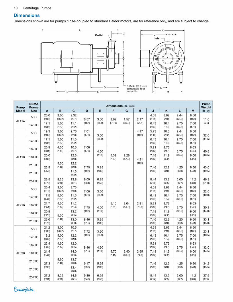
DimensionsDimensions shown are for pumps close-coupled to standard Baldor motors, are for reference only, and are subject to change.
F
A
E
G
D
CB
J H
K
L
M
InletOutlet
�.75 in. (69.8 mm), adjustable foot turned in
Pump Model
NEMA Frame Size
Dimensions, in. (mm) Pump Weight lb (kg)A B C D E F G H J K L M
JF114 56C �0.0
(508) 3.00 (76.�)
9.3� (�37) 6.57
(167) 3.50 (88.9)
3.6� (91.9)
1.57 (39.9)
�.17 (55.1)
4.53 (115)
8.6� (�19)
�.44 (6�.0)
6.50 (165) 11.0
(5.0) 145TC 17.1
(434) 5.00 (1�7)
11.1 (�8�)
6.43 (163)
10.4 (164)
�.75 (69.8)
7.00 (178)
JF118
56C 19.3 (490)
3.00 (76.�)
9.76 (�48)
7.01 (178) 3.50
(88.9)
5.39 (137)
�.�8 (57.9)
4.17 (106)
5.73 (146)
10.3 (�6�)
�.44 (6�.0)
6.50 (165) 3�.0
(14.5) 145TC 17.1
(434) 5.00 (1�7)
11.5 (�9�)
7.00 (178)
4.�1 (107)
6.43 (163)
10.4 (164)
�.75 (69.8)
7.00 (178)
18�TC �0.9 (531)
4.50 (114)
10.5 (�67) 4.50
(114)
5.�1 (13�)
9.73 (�47) 3.75
(95.�)
8.63 (340) 40.8
(18.5) 184TC �0.0
(508)
5.50 (140)
1�.5 (318)
7.18 (18�)
11.9 (30�)
9.00 (��9)
�13TC �5.9 (658)
1�.� (310) 7.75
(197) 5.�5 (133)
7.46 (189)
1�.� (310)
4.�5 (108)
9.50 (�41)
43.0 (19.5)
�15TC 11.5 (�9�)
�54TC �6.5 (673)
8.�5 (�10)
13.8 (351)
9.09 (�31)
6.�5 (159)
8.44 (�14)
13.� (335)
5.00 (1�7)
11.� (�84)
46.3 (�1.0)
JF�16
56C �0.4 (518)
3.00 (76.�)
9.75 (�48) 7.00
(178) 3.50 (88.9)
5.15 (131)
�.04 (51.8)
�.91 (73.9)
4.53 (115)
8.6� (�19)
�.44 (6�.0)
6.50 (165) ��.0
(10.0) 145TC 17.5
(444) 5.00 (1�7)
11.5 (�9�)
6.43 (163)
10.4 (164)
�.75 (69.8)
7.00 (178)
18�TC �1.7 (551)
4.50 (114)
11.� (�84) 7.75
(197) 4.50 (114)
5.�1 (13�)
9.73 (�47) 3.75
(95.�)
8.63 (340) 30.9
(14.0) 184TC �0.8
(5�8) 5.50 (140)
13.� (335)
7.18 (18�)
11.9 (30�)
9.00 (��9)
�13TC �6.6 (676)
13.0 (330)
8.46 (�15)
5.�5 (133)
7.46 (189)
1�.� (310)
4.�5 (108)
9.50 (�41)
33.1 (15.0)
JF3�6
56C �1.� (538)
3.00 (76.�)
10.5 (�67) 7.7�
(196) 3.50 (88.9)
5.70 (145)
�.40 (61.0)
�.95 (74.9)
4.53 (115)
8.6� (�19)
�.44 (6�.0)
6.50 (165) �3.1
(10.5) 145TC 18.�
(46�) 5.00 (1�7)
1�.� (310)
6.43 (163)
10.4 (164)
�.75 (69.8)
7.00 (178)
18�TC ��.4 (569)
4.50 (114)
1�.0 (305) 8.46
(�15) 4.50 (114)
5.�1 (13�)
9.73 (�47) 3.75
(95.�)
8.63 (340) 3�.0
(14.5) 184TC �1.4
(544)
5.50 (140)
14.0 (356)
7.18 (18�)
11.9 (30�)
9.00 (��9)
�13TC �7.3 (693)
13.7 (348) 9.17
(�33) 5.�5 (133)
7.46 (189)
1�.� (310)
4.�5 (108)
9.50 (�41)
34.� (15.5)
�15TC 13.4 (340)
�54TC �7.� (691)
8.�5 (�10)
14.6 (371)
9.80 (�49)
6.�5 (159)
8.44 (�14)
13.� (335)
5.00 (1�7)
11.� (�84)
37.5 (17.0)

Centrifugal Pumps 11
Standard Baldor Motors3-phase, 60 Hz, �08-�30/460 V
1750 r/min
Motor Size hp
NEMA Frame Size
Weight, lb (kg)
TEFC Washdown 1/3 56C ��.0 (10.0) —
1/� 56C ��.0 (10.0) 34.0 (15.4)
3/4 56C �6.0 (11.8) 37.0 (16.8)
1 56C 31.0 (14.1) 40.0 (18.1)
1 1/� 56C 35.0 (15.9) —
145TC 44.0 (�0.0) 51.0 (�3.1)
� 145TC 47.0 (31.3) 49.0 (��.�)
3 18�TC 74.0 (33.6)
5 184TC 81.0 (36.7) 84.0 (38.1)
7 1/� �13TC 185 (83.9) 131 (59.4)
10 �15TC 190 (86.�) 143 (64.9)
3500 r/min
Motor Size hp
NEMA Frame Size
Weight, lb (kg)
TEFC Washdown 1/� 56C — 30.0 (13.6)
3/4 56C ��.0 (10.0) 3�.0 (14.5)
1 56C �4.0 (10.9) 3�.0 (14.5)
1 1/� 56C 39.0 (17.7) 35.0 (15.9)
� 145TC 46.0 (�0.9) 44.0 (�0.0)
3 145TC 55.0 (�4.9) 53.0 (�4.0)
5 184TC 76.0 (34.5) 77.0 (34.9)
7 1/� 184TC 94.0 (4�.6) —
�13TC 97.0 (44.0) 104 (47.�)
3500 r/min
Motor Size hp
NEMA Frame Size
Weight, lb (kg)
TEFC Washdown 10 �15TC 1�7 (57.6) 131 (59.4)
15�15TC 167 (75.8) —
�54TC — 195 (88.5)
�0 �56TC �70 (1��) �74 (1�4)
�5 �84TSC 361 (164) —
30 �86TSC 383 (174) —
40 3�4TSC 486 (��0) —
50 3�6TSC 595 (�70) —
Pump Model
NEMA Frame Size
Dimensions, in. (mm) Pump Weight lb (kg)A B C D E F G H J K L M
JF3�8
145TC 19.4 (493)
5.00 (1�7)
1�.4 (315)
7.91 (�01)
3.50 (88.9)
6.4� (163)
3.03 (77.0)
4.09 (104)
6.43 (163)
10.4 (164)
�.75 (69.8)
7.00 (178)
35.3 (16.0)
18�TC ��.6 (574)
4.50 (114)
1�.� (310) 8.66
(��0) 4.50 (114)
5.�1 (13�)
9.73 (�47) 3.75
(95.�)
8.63 (�19) 44.1
(�0.0) 184TC �1.7
(551)
5.50 (140)
14.� (361)
7.18 (18�)
11.9 (30�)
9.00 (��9)
�13TC �7.5 (698)
13.9 (353) 9.37
(�38) 5.�5 (133)
7.46 (189)
1�.� (310)
4.�5 (108)
9.50 (�41)
4.63 (�1.0)
�15TC 13.6 (345)
�54TC �7.4 (696)
8.�5 (�10) 14.8
(376)
10.0 (�54)
6.�5 (159)
8.44 (�14)
13.� (335) 5.00
(1�7) 11.� (�84)
49.6 (18.5)
�56TC �9.8 (757)
10.0 (�54)
8.99 (��8)
14.7 (373)
�84TSC 33.4 (848)
9.50 (�41) 15.0
(381) 7.00 (178)
13.1 (333)
�0.8 (5�8) 5.50
(140) 1�.8 (3�5)
54.0 (�4.5)
�86TSC 11.0 (�79)
�0.5 (5�1)
3�4TSC 34.0 (864)
10.5 (�67)
19.5 (495)
10.5 (�67)
8.00 (�03)
14.6 (371)
�3.1 (587)
6.50 (165)
16.0 (406)
65.0 (�9.5)
JF438
18�TC 19.9 (505)
4.50 (114) 13.4
(340) 7.87 (�00)
4.50 (114)
7.�4 (184)
�.�0 (55.9)
3.74 (95.0)
5.�1 (13�)
9.73 (�47) 3.75
(95.�)
8.63 (�19) 48.5
(��.0) 184TC �0.9
(531)
5.50 (140)
7.18 (18�)
11.9 (30�)
9.00 (��9)
�13TC �6.7 (678)
13.1 (333) 8.58
(�18) 5.�5 (133)
7.46 (189)
1�.� (310)
4.�5 (108)
9.50 (�41)
50.7 (�3.0)
�15TC 1�.8 (3�5)
�54TC �6.6 (676)
8.�5 (�10) 14.0
(356)
9.�1 (�34)
6.�5 (159)
8.44 (�14)
13.� (335) 5.00
(1�7) 11.� (�84)
55.1 (�5.0)
�56TC �9.0 (737)
10.0 (�54)
8.99 (��8)
14.7 (373)
�84TSC 3�.6 (8�8)
9.50 (�41) 14.�
(361) 7.00 (178)
13.1 (333)
�0.8 (5�8) 5.50
(140) 1�.8 (3�5)
59.6 (�7.0)
�86TSC 11.0 (�79)
�0.5 (5�1)
3�4TSC 33.� (843)
10.5 (�67) 18.7
(475) 9.69 (�46)
8.00 (�03)
14.6 (371)
�3.1 (587)
6.�5 (159)
16.0 (406)
71.6 (3�.5)
3�6TSC 34.7 (881)
1�.0 (305)

Centrifugal Pumps 1�
Ordering Information
JF 216 M DG 18T - S 00 S E 06 S T S 08 A B C D - E F G H J K L M N
Typical Ordering NumberBuild centrifugal pump ordering number by combining the designators in the sequence shown below.
ModelKwik-Clamp Port Connection Sizes Inlet Outlet 114 = 1 1/� in. 1 1/� in. 118 = 1 1/� in. 1 1/� in. 216 = � in. 1 1/� in. 326 = 3 in. � in. 328 = 3 in. � in. 438 = 4 in. 3 in.
A
Casing Connection M = Sanitary clamp W = Weld
B
Shaft Seal Single mechanicalC
Motor Adapter Kit, NEMA Frame
56T = 56C 14T = 145TC 18T = 18�TC and 184TC 21T = �13TC and �15TC 25T = �54TC and �56TC 28T = �84TSC and �86TSC 32T = 3�4TSC and 3�6TSC
D
Tri-Leg Kit S = Stationary tri-leg assembly N = None
E
Casing Drain 00 = No casing drain DH = 1/� in. Kwik-Clamp,
horizontal mount DV = 1/� in. Kwik-Clamp,
vertical mount
F
Shaft Seal Material S = Carbon to silicone carbide 1 = Silicone carbide to silicone
carbide
G
Elastomer Material E = EPDM V = Fluorocarbon FKM
H
Internal Wetted Components Surface Roughness, Ra
3� µin. (0.81 µm)
K
Motor EnclosureLeave blank if no motor ordered. T = TEFC W = TEFC-washdown duty E = Explosion proof
L
Motor Electrical RequirementsLeave blank if no motor ordered. Phase Hz V S = 3 60 �30/460 B = 3 60 �08 C = 3 60 575 D = 1 60 115 E = 1 60 �30 F = 3 50 190/380 G = 3 50 380/460 H = 3 50 ��0/380/440 J = 3 50 ��0/380/415
M
Motor SizeLeave blank if no motor ordered.TEFC Enclosure hp r/min Frame 01 = 1/3 1750 56C 02 = 1/� 1750 56C 03 = 3/4 1750 56C 04 = 3/4 3500 56C 05 = 1 1750 56C 06 = 1 3500 56C 07 = 1 1/� 1750 56C 08 = 1 1/� 3500 56C 09 = 1 1/� 1750 145TC 10 = � 1750 145TC 11 = � 3500 145TC 12 = 3 1750 18�TC 13 = 3 3500 145TC 14 = 5 1750 184TC 15 = 5 3500 184TC 16 = 7 1/� 1750 �13TC 17 = 7 1/� 3500 184TC 18 = 7 1/� 3500 �13TC 19 = 10 1750 �15TC 20 = 10 3500 �15TC 21 = 15 3500 �15TC 22 = �0 3500 �56TC 23 = �5 3500 �84TSC 24 = 30 3500 �86TSC 25 = 40 3500 3�4TSC 26 = 50 3500 3�6TSC
Washdown Enclosure hp r/min Frame 27 = 1/� 1750 56C 28 = 1/� 3500 56C 29 = 3/4 1750 56C 30 = 3/4 3500 56C 31 = 1 1750 56C 32 = 1 3500 56C 33 = 1 1/� 1750 145TC 34 = 1 1/� 3500 56C 35 = � 1750 145TC 36 = � 3500 145TC 37 = 3 1750 18�TC 38 = 3 3500 145TC 39 = 5 1750 184TC 40 = 5 3500 184TC 41 = 7 1/� 1750 �13TC 42 = 7 1/� 3500 �13TC 43 = 10 1750 �15TC 44 = 10 3500 �15TC 45 = 15 3500 �54TC 46 = �0 3500 �56TC
N
01 = �.95 (74.9) 02 = 3.15 (80.0) 03 = 3.35 (85.1) 04 = 3.55 (90.�) 05 = 3.75 (95.3) 06 = 3.95 (100) 07 = 4.15 (105) 08 = 4.35 (110) 09 = 4.55 (116) 10 = 4.75 (1�1) 11 = 4.95 (1�6) 12 = 5.15 (131) 13 = 5.35 (136)
14 = 5.55 (141) 15 = 5.75 (146) 16 = 5.95 (151) 17 = 6.15 (156) 18 = 6.35 (161) 19 = 6.55 (166) 20 = 6.75 (171) 21 = 6.95 (177) 22 = 7.15 (18�) 23 = 7.35 (187) 24 = 7.55 (19�) 25 = 7.75 (197) 26 = 7.99 (�03)
Impeller Size,➀ in. (mm)J
➀ Nominal maximum impeller sizes: ■ JF114 model—4 in. ■ JF�16 and JF3�6 models—6 in. ■ JF118, JF3�8, and JF438 models—8 in.
For material and motor component options, contact your authorized Swagelok sales and service representative.
Certain component combinations may not be available; contact your authorized Swagelok representative for more information.

13 Centrifugal Pumps
Options and AccessoriesContact your authorized Swagelok representative for information about:
■Single mechanical seal options
■ Tungsten carbide to silicone carbide with fluorocarbon FKM
■Port connection options
■ Acme (bevel-seat) threads
■ Male and female NPT threads
■ Flanges
■ Tube butt welds
■ Adapters
■Enhanced inside-diameter surface finishes—15 µin. (0.38 µm) Ra electropolished
■Material test reports for all wetted stainless steel components
■Casing drains
■ Optional locations
■Motor options
■ Single-phase 60 Hz, 110/1�0 V
■ Explosion proof (various class and division ratings)
■ Premium efficiency
■ All stainless steel
■ Inverter duty for high turn-down ratios
■Variable-speed, alternating-current motor drives
Enclosure options
■ Chassis mount (panel mount)
■ NEMA1, NEMA4 and 1�, NEMA4X
■Water-for-injection (WFI) pumps
Standard
■ Material test reports for all wetted stainless steel components
■ 15 µin. (0.38 µm) Ra electropolished inside diameter
■ Surface finish certification
■ Casing drain
■ Double mechanical seals (silicone carbide with EPDM)
Optional
■ Seal flush piping and accessories

Safe Product SelectionWhen selecting a product, the total system design must be considered to ensure safe, trouble-free performance. Function, material compatibility, adequate ratings, proper installation, operation, and maintenance are the responsibilities of the system designer and user.
Caution: Do not mix or interchange pump parts with those of other manufacturers.
Warranty InformationSwagelok products are backed by The Swagelok Limited Lifetime Warranty. For a copy, visit swagelok.com or contact your authorized Swagelok representative.
Swagelok—TM Swagelok Company Baldor—TM Baldor Electric Company© �003, �004, �007, �008 Swagelok CompanyPrinted in U.S.A., GLIAugust �008, R3MS-03-04