Embed Size (px)
Citation preview
Bopp & Reuther Messtechnik GmbH
Am Neuen Rheinhafen 4
67346 Speyer - Germany
Phone: +49 (6232) 657 - 0
Fax: +49 (6232) 657 - 505
www.bopp-reuther.de
Dimensions, weights and other
technical data are subject to changes.
Printed in the
Federal Republic of Germany
A-EN-03661-00RevD
Latest Mod. 09/2009
1 of 10
Centrifugal Gas Separator
ZGA
Operating Manual
ZGA Centrifugal Gas Separator
Page 2 of 10 Bopp & Reuther Messtechnik GmbH
Table of Contents
1 IDENTIFICATION ...................................................................................................................................... 3
1.1 SUPPLIER/MANUFACTURER 3
1.2 TYPE OF PRODUCT 3
1.3 NAME OF PRODUCT 3
1.4 DATE OF RELEASE 3
1.5 VERSION NO. 3
2 AREA OF APPLICATION .......................................................................................................................... 3
3 SYSTEM DESIGN ..................................................................................................................................... 3
4. TECHNICAL DATA ................................................................................................................................... 4
4.1 OPERATING TEMPERATURE 4
4.2 NOMINAL PRESSURE: 4
4.3 PRESSURE DROP AND THROUGHPUT 4
5 CONSTRUCTIVE DESIGN ....................................................................................................................... 4
5.1 MODEL/DIMENSIONS 4
5.2 WEIGHTS 6
5.3 MATERIALS 7
5.4 PORT AND SIGHT GLASS POSITIONS 8
6 CERTIFICATES AND APPROVALS ......................................................................................................... 8
7 ORDER INFORMATION ........................................................................................................................... 8
8 STANDARDS AND DIRECTIVES ............................................................................................................. 8
9 COMMISSIONING AND OPERATION ...................................................................................................... 8
10 SAFETY INFORMATION ........................................................................................................................ 9
11 DISPOSAL AND DECOMMISSIONING .................................................................................................. 9
12 MAINTENANCE ...................................................................................................................................... 9
13 REPAIRS ................................................................................................................................................. 9
14 SERVICE ADDRESSES........................................................................................................................ 10
ZGA Centrifugal Gas Separator
Bopp & Reuther Messtechnik GmbH Page 3 of 10
1 Identification
1.1 Supplier/Manufacturer
Bopp & Reuther Messtechnik GmbH
1.2 Type of Product
ZGA centrifugal gas separator with float-deaeration
device and sight glass
1.3 Name of Product
ZGA Centrifugal Gas Separator
1.4 Date of Release
September 2009
1.5 Version No.
A-EN-03661-00RevD
2 Area of Application
In order to prevent measuring errors caused by free
air or gas when using volumetric meters to
measure liquid quantity, gas separators are
installed in front of the meter (forward flow) for
liquids with a dynamic viscosity of < 20 mPa.s (at
20°C).
The German weights and measures regulations
(Eichordnung) specify the use of gas separators for
liquids up to 20 mPas in measuring systems with
pump operation which are subject to calibration.
Centrifugal gas separators in connection with oval
wheel meters comply with the regulations for the
calibration of measuring systems in Germany and
other countries.
Bopp & Reuther centrifugal gas separators have
EEC qualification approval and are therefore
approved for EEC initial calibration.
3 System Design
The gas separator is made of a welded pressure
vessel with an integrated automatic float-deaeration
device. For liquid gas measuring systems, it is also
possible to use gas separators with an orifice plate
installed between 2 valves in the degassing or
return pipe (to the storage tank). The orifice plate is
designed to allow a backflow of max. 5%. The
valves are sealed in an open position. The liquid
enters tangentially at the upper port, resulting in a
swirling flow inside the gas separator. This swirling
motion is sustained by the tangential outgoing
liquid at the outlet port.
The distribution of pressure in the swirling flow
causes any air or gas to escape via the ventilating
valve.
The direction of flow is indicated by an arrow on the
inlet port. The sight glass is used to monitor the
float and the liquid.
A sign attached to the gas separator specifically
indicates two important points:
The maximum flow rate permitted by the
German Board of Weights and Measures.
Only draw liquid when it is visible in the
sight glass. Throttle if foam forms.
Furthermore, a lead seal at the information sign is
used to fix a calibration mark after measuring
system calibration.
The gas separator can also be equipped with a
level limit switch or level indicator.
ZGA Centrifugal Gas Separator
Page 4 of 10 Bopp & Reuther Messtechnik GmbH
4. Technical Data
4.1 Operating Temperature
Standard: -10 to max. +100 °C
Low temperature model
(-140 to -10 °C) on request
4.2 Nominal Pressure:
PN 10, 16, 25 and 40
PN 63 and 100 on request
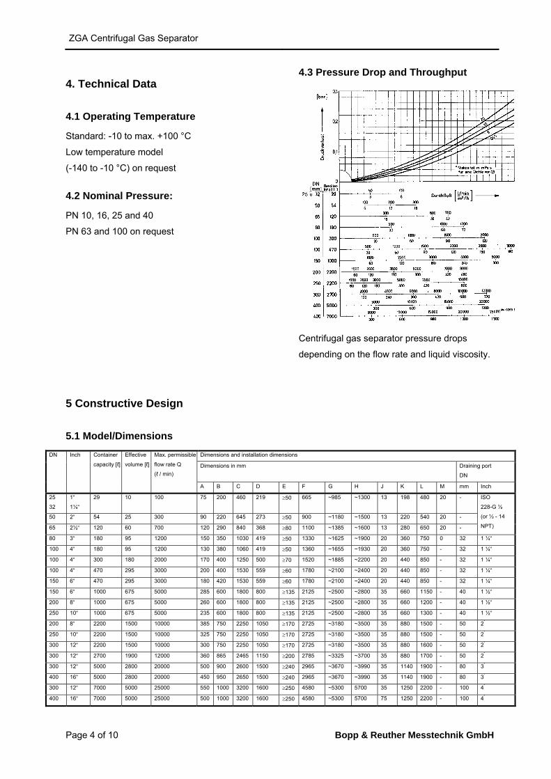
4.3 Pressure Drop and Throughput
Centrifugal gas separator pressure drops
depending on the flow rate and liquid viscosity.
5 Constructive Design
5.1 Model/Dimensions
DN Inch Container
capacity [ℓ]
Effective
volume [ℓ]
Max. permissible.
flow rate Q
(ℓ / min)
Dimensions and installation dimensions
Dimensions in mm Draining port
DN
A B C D E F G H J K L M mm Inch
25
32
1“
1¼“
29 10 100 75 200 460 219 50 665 ~985 ~1300 13 198 480 20 - ISO
228-G ½
(or ½ - 14
NPT)
50 2“ 54 25 300 90 220 645 273 50 900 ~1180 ~1500 13 220 540 20 -
65 2½“ 120 60 700 120 290 840 368 80 1100 ~1385 ~1600 13 280 650 20 -
80 3“ 180 95 1200 150 350 1030 419 50 1330 ~1625 ~1900 20 360 750 0 32 1 ¼“
100 4“ 180 95 1200 130 380 1060 419 50 1360 ~1655 ~1930 20 360 750 - 32 1 ¼“
100 4“ 300 180 2000 170 400 1250 500 70 1520 ~1885 ~2200 20 440 850 - 32 1 ¼“
100 4“ 470 295 3000 200 400 1530 559 60 1780 ~2100 ~2400 20 440 850 - 32 1 ¼“
150 6“ 470 295 3000 180 420 1530 559 60 1780 ~2100 ~2400 20 440 850 - 32 1 ¼“
150 6“ 1000 675 5000 285 600 1800 800 135 2125 ~2500 ~2800 35 660 1150 - 40 1 ½“
200 8“ 1000 675 5000 260 600 1800 800 135 2125 ~2500 ~2800 35 660 1200 - 40 1 ½“
250 10“ 1000 675 5000 235 600 1800 800 135 2125 ~2500 ~2800 35 660 1300 - 40 1 ½“
200 8“ 2200 1500 10000 385 750 2250 1050 170 2725 ~3180 ~3500 35 880 1500 - 50 2“
250 10“ 2200 1500 10000 325 750 2250 1050 170 2725 ~3180 ~3500 35 880 1500 - 50 2“
300 12“ 2200 1500 10000 300 750 2250 1050 170 2725 ~3180 ~3500 35 880 1600 - 50 2“
300 12“ 2700 1900 12000 360 865 2465 1150 200 2785 ~3325 ~3700 35 880 1700 - 50 2“
300 12“ 5000 2800 20000 500 900 2600 1500 240 2965 ~3670 ~3990 35 1140 1900 - 80 3“
400 16“ 5000 2800 20000 450 950 2650 1500 240 2965 ~3670 ~3990 35 1140 1900 - 80 3“
300 12“ 7000 5000 25000 550 1000 3200 1600 250 4580 ~5300 5700 35 1250 2200 - 100 4“
400 16“ 7000 5000 25000 500 1000 3200 1600 250 4580 ~5300 5700 75 1250 2200 - 100 4“
ZGA Centrifugal Gas Separator
Bopp & Reuther Messtechnik GmbH Page 5 of 10
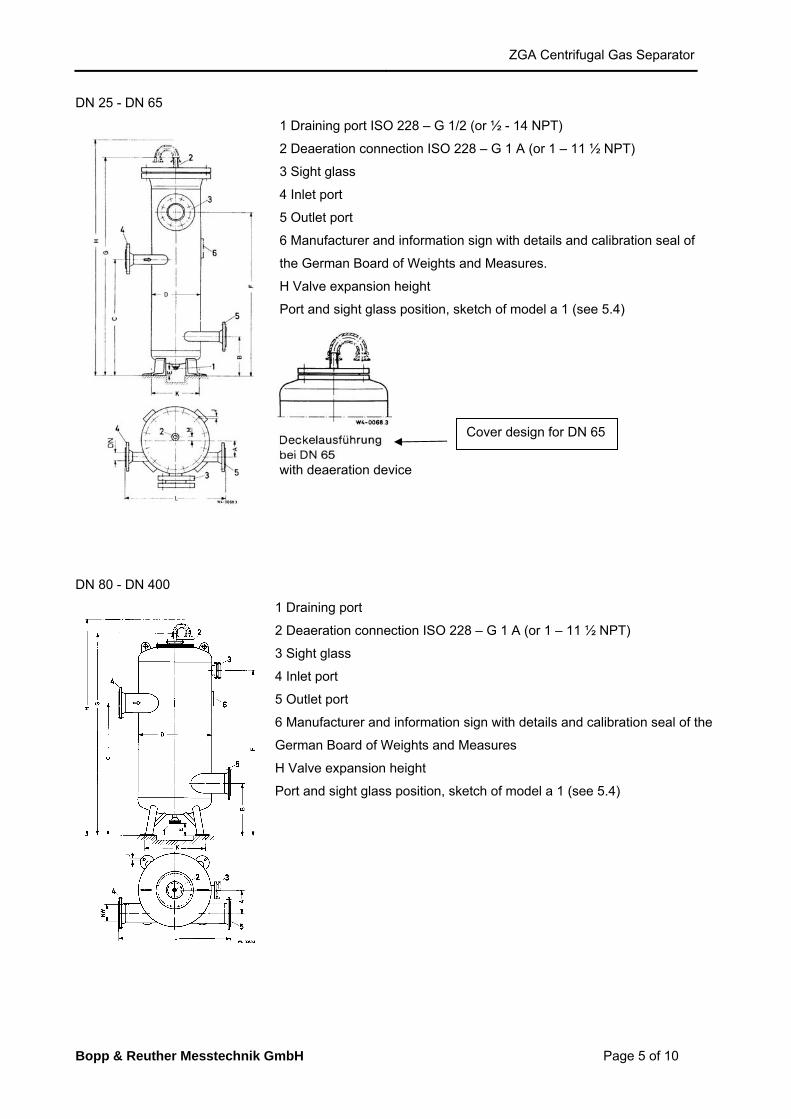
DN 25 - DN 65
1 Draining port ISO 228 – G 1/2 (or ½ - 14 NPT)
2 Deaeration connection ISO 228 – G 1 A (or 1 – 11 ½ NPT)
3 Sight glass
4 Inlet port
5 Outlet port
6 Manufacturer and information sign with details and calibration seal of
the German Board of Weights and Measures.
H Valve expansion height
Port and sight glass position, sketch of model a 1 (see 5.4)
with deaeration device
DN 80 - DN 400
1 Draining port
2 Deaeration connection ISO 228 – G 1 A (or 1 – 11 ½ NPT)
3 Sight glass
4 Inlet port
5 Outlet port
6 Manufacturer and information sign with details and calibration seal of the
German Board of Weights and Measures
H Valve expansion height
Port and sight glass position, sketch of model a 1 (see 5.4)
Cover design for DN 65
ZGA Centrifugal Gas Separator
Page 6 of 10 Bopp & Reuther Messtechnik GmbH
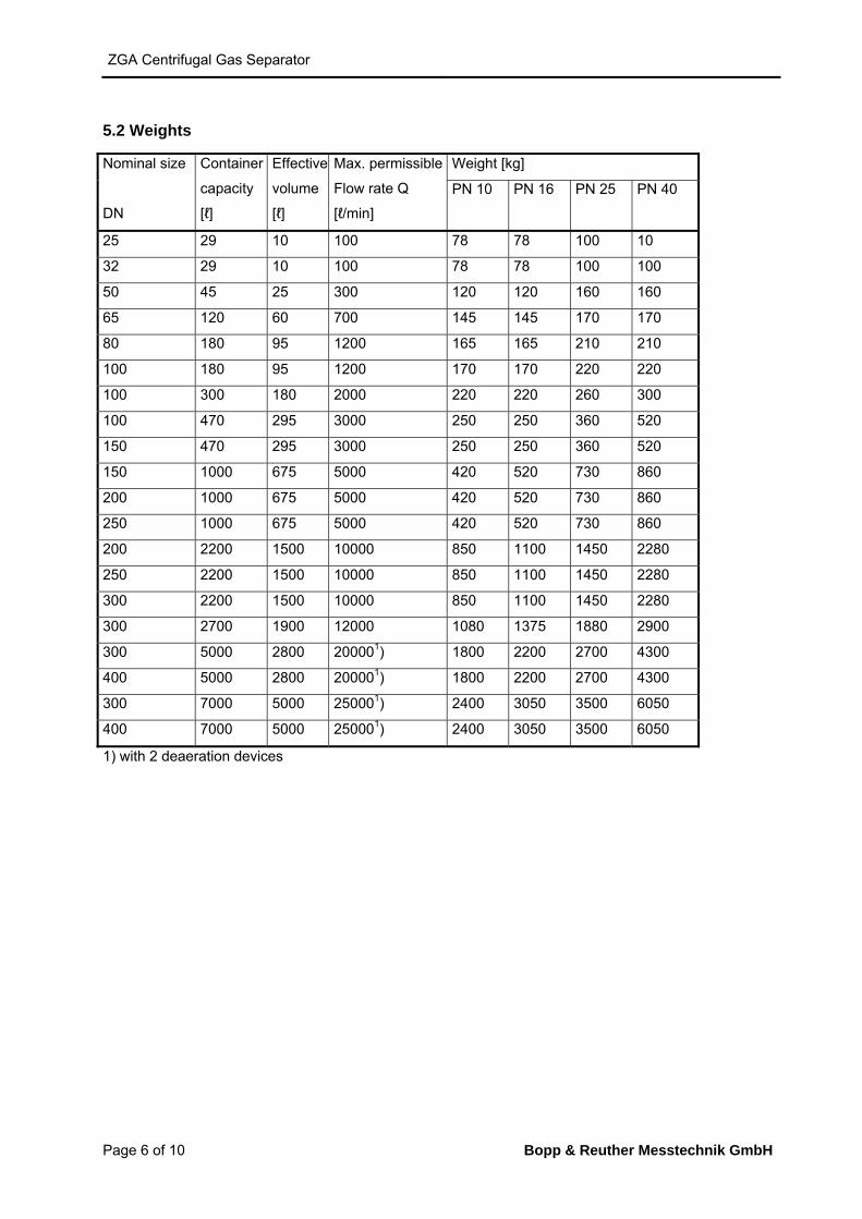
5.2 Weights
Nominal size
DN
Container
capacity
[ℓ]
Effective
volume
[ℓ]
Max. permissible
Flow rate Q
[ℓ/min]
Weight [kg]
PN 10 PN 16 PN 25 PN 40
25 29 10 100 78 78 100 10
32 29 10 100 78 78 100 100
50 45 25 300 120 120 160 160
65 120 60 700 145 145 170 170
80 180 95 1200 165 165 210 210
100 180 95 1200 170 170 220 220
100 300 180 2000 220 220 260 300
100 470 295 3000 250 250 360 520
150 470 295 3000 250 250 360 520
150 1000 675 5000 420 520 730 860
200 1000 675 5000 420 520 730 860
250 1000 675 5000 420 520 730 860
200 2200 1500 10000 850 1100 1450 2280
250 2200 1500 10000 850 1100 1450 2280
300 2200 1500 10000 850 1100 1450 2280
300 2700 1900 12000 1080 1375 1880 2900
300 5000 2800 200001) 1800 2200 2700 4300
400 5000 2800 200001) 1800 2200 2700 4300
300 7000 5000 250001) 2400 3050 3500 6050
400 7000 5000 250001) 2400 3050 3500 6050
1) with 2 deaeration devices
ZGA Centrifugal Gas Separator
Bopp & Reuther Messtechnik GmbH Page 7 of 10
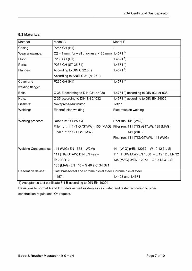
5.3 Materials
Material Model A Model F
Casing:
Wear allowance:
P265 GH (HII)
C2 = 1 mm (for wall thickness < 30 mm)
-
1.4571 1)
Floor:
Ports:
Flanges:
P265 GH (HII)
P235 GH (ST 35.8 I)
According to DIN C 22.8 1)
According to ANSI C 21 (A105 1)
1.4571 1)
1.4571 1)
1.4571 1)
Cover and
welding flange:
P265 GH (HII) 1.4571 1)
Bolts: C 35 E according to DIN 931 or 938 1.4751 1) according to DIN 931 or 938
Nuts:
Gaskets:
C 35 according to DIN EN 24032
Novapress-Multi/Viton
1.4571 1) according to DIN EN 24032
Teflon
Welding:
Welding process:
Welding Consumables:
Electrofusion welding
Root run: 141 (WIG)
Filler run: 111 (TIG /GTAW), 135 (MAG)
Final run: 111 (TIG/GTAW)
141 (WIG) EN 1668 – W2Mo
111 (TIG/GTAW) DIN EN 499 –
E420RR12
135 (MAG) EN 440 – G 46 2 C G4 Si 1
Electrofusion welding
Root run: 141 (WIG)
Filler run: 111 (TIG /GTAW), 135 (MAG)
141 (WIG)
Final run: 111 (TIG/GTAW), 141 (WIG)
141 (WIG) prEN 12072 – W 19 12 3 L Si
111 (TIG/GTAW) EN 1600 – E 19 12 3 LR 32
135 (MAG) 9rEN 12072 – G 19 12 3 L Si
Deaeration device: Cast brass/steel and chrome nickel steel
1.4571
Chrome nickel steel
1.4408 and 1.4571
1) Acceptance test certificate 3.1 B according to DIN EN 10204
Deviations to normal A and F models as well as devices calculated and tested according to other
construction regulations: On request.
ZGA Centrifugal Gas Separator
Page 8 of 10 Bopp & Reuther Messtechnik GmbH
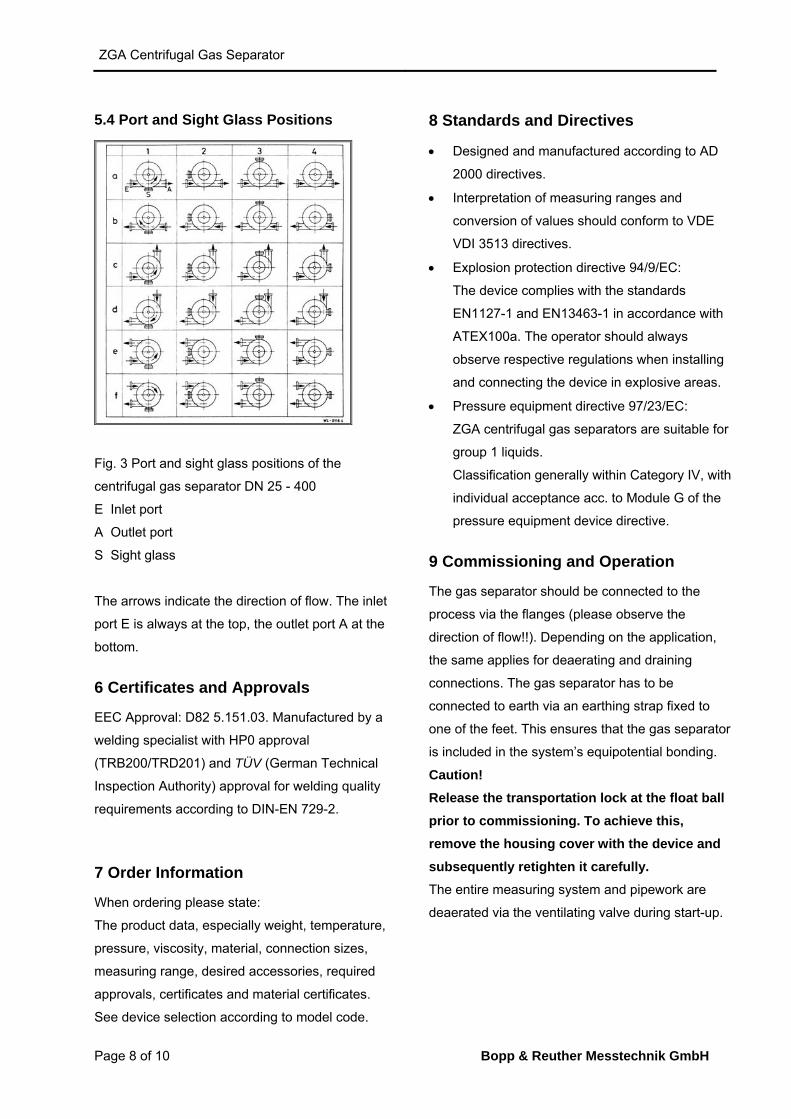
5.4 Port and Sight Glass Positions
Fig. 3 Port and sight glass positions of the
centrifugal gas separator DN 25 - 400
E Inlet port
A Outlet port
S Sight glass
The arrows indicate the direction of flow. The inlet
port E is always at the top, the outlet port A at the
bottom.
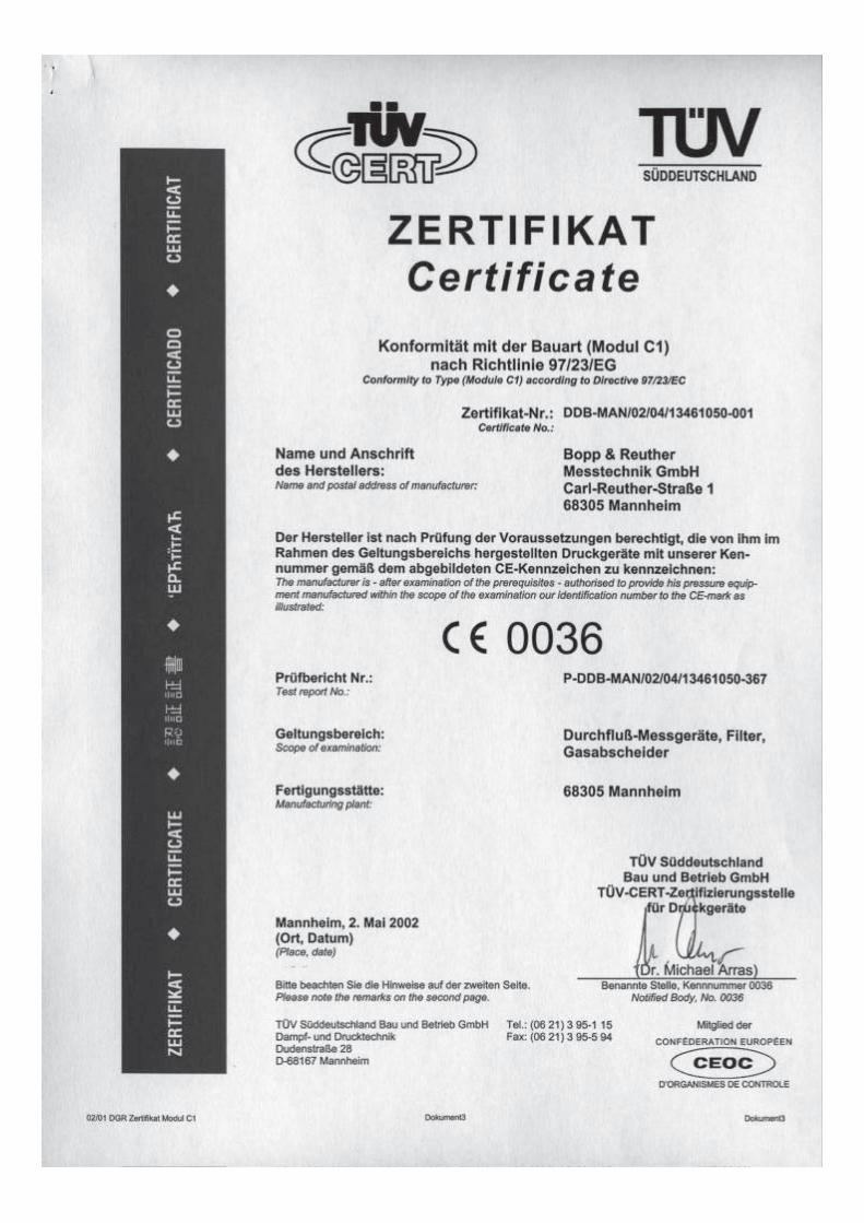
6 Certificates and Approvals
EEC Approval: D82 5.151.03. Manufactured by a
welding specialist with HP0 approval
(TRB200/TRD201) and TÜV (German Technical
Inspection Authority) approval for welding quality
requirements according to DIN-EN 729-2.
7 Order Information
When ordering please state:
The product data, especially weight, temperature,
pressure, viscosity, material, connection sizes,
measuring range, desired accessories, required
approvals, certificates and material certificates.
See device selection according to model code.
8 Standards and Directives
Designed and manufactured according to AD
2000 directives.
Interpretation of measuring ranges and
conversion of values should conform to VDE
VDI 3513 directives.
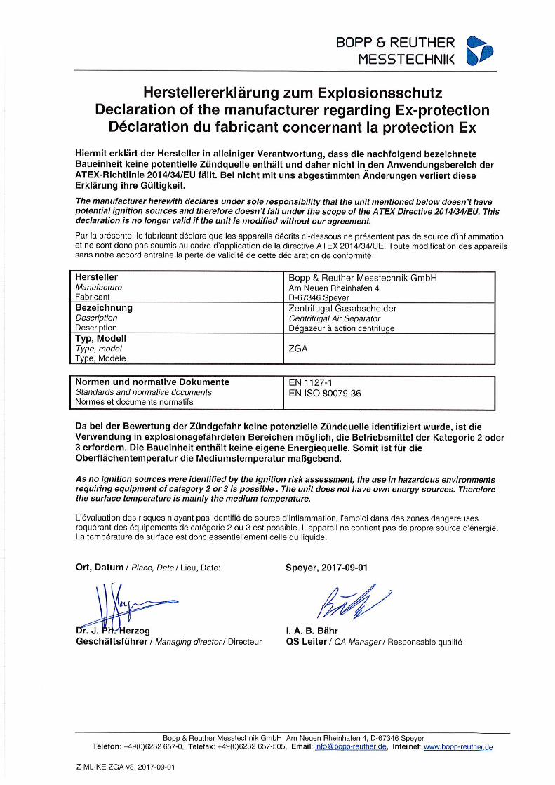
Explosion protection directive 94/9/EC:
The device complies with the standards
EN1127-1 and EN13463-1 in accordance with
ATEX100a. The operator should always
observe respective regulations when installing
and connecting the device in explosive areas.
Pressure equipment directive 97/23/EC:
ZGA centrifugal gas separators are suitable for
group 1 liquids.
Classification generally within Category IV, with
individual acceptance acc. to Module G of the
pressure equipment device directive.
9 Commissioning and Operation
The gas separator should be connected to the
process via the flanges (please observe the
direction of flow!!). Depending on the application,
the same applies for deaerating and draining
connections. The gas separator has to be
connected to earth via an earthing strap fixed to
one of the feet. This ensures that the gas separator
is included in the system’s equipotential bonding.
Caution!
Release the transportation lock at the float ball
prior to commissioning. To achieve this,
remove the housing cover with the device and
subsequently retighten it carefully.
The entire measuring system and pipework are
deaerated via the ventilating valve during start-up.
ZGA Centrifugal Gas Separator
Bopp & Reuther Messtechnik GmbH Page 9 of 10
10 Safety Information
The centrifugal gas separator should only be used
for its intended area of application (see 2). Always
observe the pressure and temperature limits stated
on the type plate as well as all other technical data
and safety information during device installation,
commissioning and operation.
Always observe national and international
regulations concerning the operation of devices
and systems under pressure.
Prior to installation, the operator has to ensure that
the pressure bearing parts have not been damaged
during transportation.
The devices have to be installed, operated and
serviced by qualified personnel. The operator has
the responsibility to ensure that the personnel have
received sufficient and appropriate training. In
cause of doubt, please contact the manufacturer.
Only measure liquids to which the materials of the
pressure bearing elements are resistant.
Only release flanges, connections for deaerating or
draining purposes, or the sight glass when the
devices are depressurised.
Only use the original spare parts specified by the
manufacturer when replacing components. In the
case of non-compliance, warranty shall not apply.
Carefully select gaskets or sealing elements
according to the operating instruction specifications
(see 5.3).
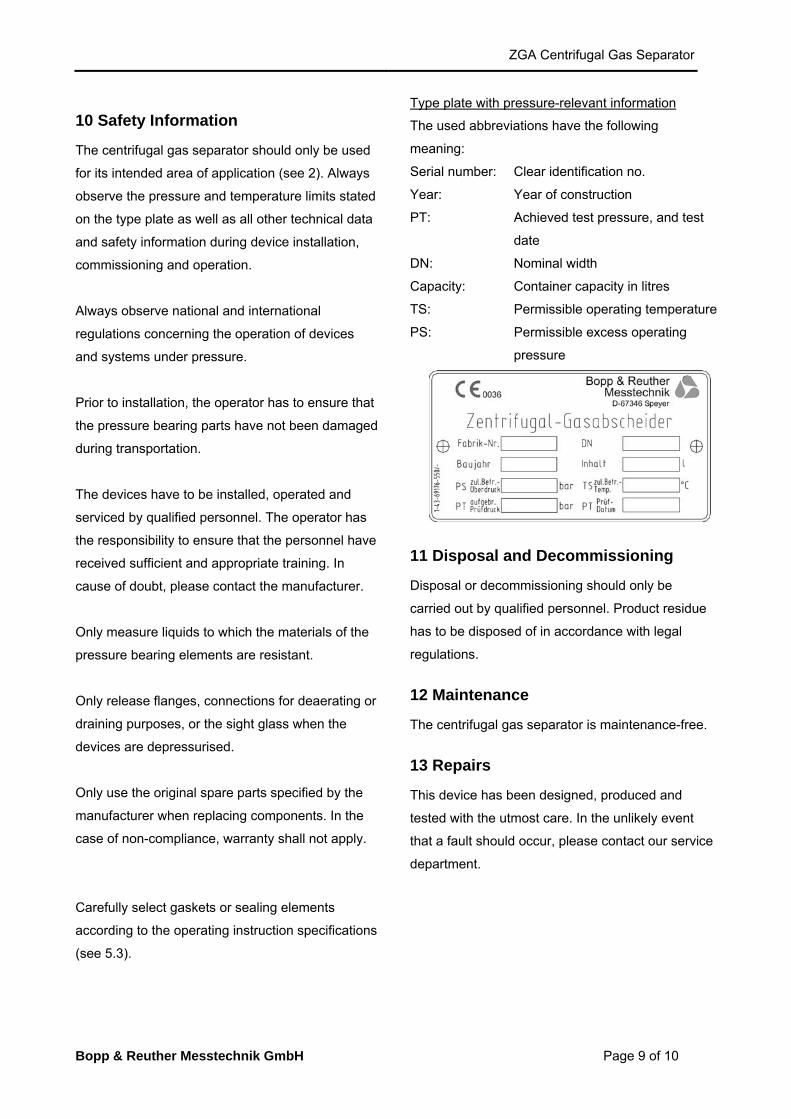
Type plate with pressure-relevant information
The used abbreviations have the following
meaning:
Serial number: Clear identification no.
Year: Year of construction
PT: Achieved test pressure, and test
date
DN: Nominal width
Capacity: Container capacity in litres
TS: Permissible operating temperature
PS: Permissible excess operating
pressure
11 Disposal and Decommissioning
Disposal or decommissioning should only be
carried out by qualified personnel. Product residue
has to be disposed of in accordance with legal
regulations.
12 Maintenance
The centrifugal gas separator is maintenance-free.
13 Repairs
This device has been designed, produced and
tested with the utmost care. In the unlikely event
that a fault should occur, please contact our service
department.
Bopp & Reuther Messtechnik GmbH
Am Neuen Rheinhafen 4
67346 Speyer - Germany
Phone: +49 (6232) 657 - 0
Fax: +49 (6232) 657 - 505
www.bopp-reuther.de
Dimensions, weights and other
technical data are subject to changes.
Printed in the
Federal Republic of Germany
A-EN-03661-00RevD
Latest Mod. 09/2009
10 of 10
14 Service Addresses
Bopp & Reuther Messtechnik GmbH
Service
Am Neuen Rheinhafen 4
D-67346 Speyer
Phone: +49 (6232) 657-402
Fax: +49 (6232) 657 561
Bopp & Reuther Messtechnik GmbH
Münchener Str. 23
D-85123 Karlskron
Industrial Estate Brautlach, on the B 13
Phone: +49 (8450) 928330
Fax: +49 (8450) 928332