Embed Size (px)
Citation preview

Wolter GmbH+Co KG Am Wasen 11D-76316 Malsch-Vö.Telefon 07204 / 9201-0Telefax 07204 / 9201-11http://www.wolterfans.de M08.6
Radialventilatoren- keilriemengetrieben- ein- und zweiseitig saugend- mit vor- und rückwerts-
gekrümmten Schaufeln
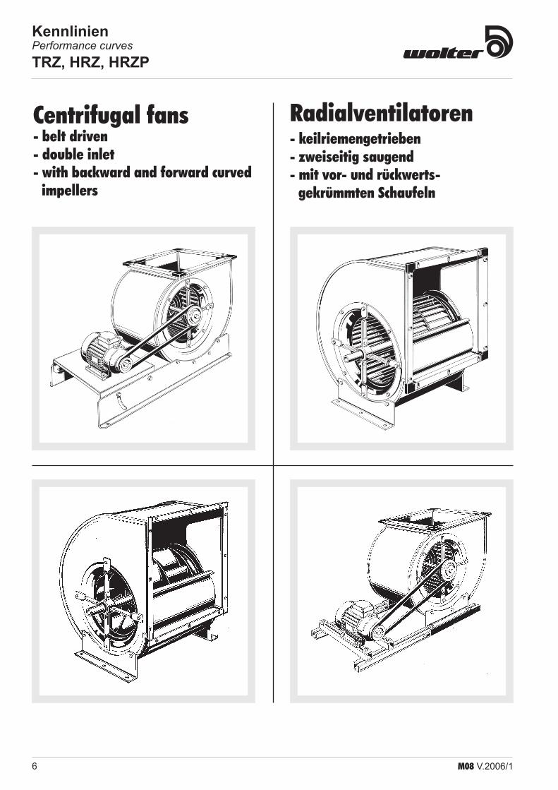
Centrifugal fans- belt driven- double inlet - single inlet- with backward and forward curved
impellers

Symbole und FormelzeichenSymbols and technical formula symbols
Größe Symbol Benennung Designation Einheit
Unit
A Querschnittsfläche Cross-section m²
c Strömungsgeschwindigkeit Flow speed m/s
C400V Betriebskondensator Capacitor µF
D2 Durchmesser des Laufrades Impeller diameter m
d Rohrdurchmesser Pipe diameter m
dg gleichwertiger Durchmesser Equivalent diameter m
g Fallbeschleunigung Gravitational speed acceleration m/s²
IN Nennstrom Rated current A
IA / IN Verhältnis Anlaufstrom zu Nennstrom Ratio of starting current to rated current
D I Stromanstieg bei Teilspannung Current increase in component voltage area %
l Rohr- bzw. Kanallänge Pipe or channel length m
LPA A-bewerteter Schalldruckpegel Sound pressure level A-weighted dB(A)
LWA A-bewerteter Schalleistungspegel Sound power level A-weighted dB(A)
LWA2 Schalleistungspegel zur Umgebung Sound power level to surrounding dB(A)
LWA3 Ansaugkanalschalleistungspegel Inlet sound power level induct dB(A)
LWA4 Ausblaskanalschalleistungspegel Outlet sound power level induct dB(A)
LWA5 Freiansaug-Schalleistungspegel Inlet sound power level unducted dB(A)
LWA6 Freiausblas-Schalleistungspegel Outlet sound power level unducted dB(A)
n Drehzahl Speed 1/min (bzw. 1/s)
P1 Motoraufnahmeleistung motor power consumption kW (bzw. W)
pst (pfa) statischer Druck Static pressure Pa
∆ pst Differenz der statischen Drücke Differential static pressure Pa
D pfa min erforderlicher statischer Mindestgegendruck min. required counter pressure Pa
pd dynamischer Druck Dynamic pressure Pa
pd2 dynamischer Druck am Ventilatoraustritt Dynamic pressure at fan outlet Pa
∆ pd Differenz der statischen Drücke Differential dynamic pressure Pa
pt Gesamtdruck Total pressure Pa
∆ pt Differenz der Gesamtdrücke Difference of total pressures Pa
T Kelvin-Temperatur Temperature in Kelvin K
t Celsius-Temperatur Temperature in Celsius °C
tR max. zulässige Fördertemperatur max. permissable medium temperature °C
u2 Umfangsgeschwindigkeit des Laufrades (außen) Circumferential speed of the impeller (outside) m/s
V .
Volumenstrom Volume flow m³/h (bzw. m³/s)
ρ Dichte des Fördermediums Density of medium kg/m³
η Wirkungsgrad Efficiency -
ϕ Volumenzahl Volume number -
ψ Druckzahl Pressure number -
ζ Widerstandsbeiwert Coefficient of drag -
λR Rohr- bzw. Kanalreibungsbeiwert Coefficient of friction of channel or pipe -
Symbol Bedeutung / Meaning Symbol Bedeutung / Meaning Symbol Bedeutung / Meaning
5-Stufen-Steuergerät, transformatorisch5-step transformer control
DrehzahlumschalterSpeed control switch
SchaltplanWiring diagram
Steuergerät, stufenlos, transformatorischContinuously adjustable transformer control
GeräteausschalterOff-Switch
explosionsgeschütztflame proof
Steuergerät, stufenlos, elektronischContinuously adjustable electronic control
GewichtWeight
AbmessungenDimensions
MotorschutzschalterMotor protection switch
SchutzartProtection class
ZubehörAccessories

1M08 V.2006/1
Table of Content . . . . . . . . . . . . . . . . . . . . . . . . . . . . . . 1
Technical description . . . . . . . . . . . . . . . . . . . . . . . . . . 2General information . . . . . . . . . . . . . . . . . . . . . . . . . . 2Fan casings . . . . . . . . . . . . . . . . . . . . . . . . . . . . . . . . 2Impellers . . . . . . . . . . . . . . . . . . . . . . . . . . . . . . . . . . 2Shaped inlets . . . . . . . . . . . . . . . . . . . . . . . . . . . . . . . 3Shafts . . . . . . . . . . . . . . . . . . . . . . . . . . . . . . . . . . . . 3Bearings . . . . . . . . . . . . . . . . . . . . . . . . . . . . . . . . . . 3Fan type code . . . . . . . . . . . . . . . . . . . . . . . . . . . . . . 3Sound levels . . . . . . . . . . . . . . . . . . . . . . . . . . . . . . . 4Performance curves . . . . . . . . . . . . . . . . . . . . . . . . . 5
Performance curves . . . . . . . . . . . . . . . . . . . . . . . . . . . 6TRZ, HRZ, HRZP . . . . . . . . . . . . . . . . . . . . . . . . . . . . 6
Dimensions . . . . . . . . . . . . . . . . . . . . . . . . . . . . . . . . . 42TRZ, HRZ, HRZP . . . . . . . . . . . . . . . . . . . . . . . . . . . 42
Performance curves . . . . . . . . . . . . . . . . . . . . . . . . . . 53TRE, HRE . . . . . . . . . . . . . . . . . . . . . . . . . . . . . . . . . 53
Dimensions . . . . . . . . . . . . . . . . . . . . . . . . . . . . . . . . . 84TRE, HRE . . . . . . . . . . . . . . . . . . . . . . . . . . . . . . . . . 84
Performance curves . . . . . . . . . . . . . . . . . . . . . . . . . 100TRZ 215 . . . . . . . . . . . . . . . . . . . . . . . . . . . . . . . . . 100
Dimensions . . . . . . . . . . . . . . . . . . . . . . . . . . . . . . . . 101TRZ 215 . . . . . . . . . . . . . . . . . . . . . . . . . . . . . . . . . 101
Technical Informations . . . . . . . . . . . . . . . . . . . . . . . . 102Fan Laws - Proportional Laws . . . . . . . . . . . . . . . . 102
Coordination fan plant . . . . . . . . . . . . . . . . . . . . . . . . 1031. Characteristic Fan Curve . . . . . . . . . . . . . . . . . 1032. Characteristic Curve of the Plant (Resistance Parabola) . . . . . . . . . . . . . . . . . . . . . 1033. Coordination between Fan and Plant . . . . . . . . 103
Operating and maintenance instructions TRZ / TRE and HRZ / HRE . . . . . . . . . . . . . . . . . . . 104
Symbols and technical formula symbols . . . . . . . . . . 105
Inhaltsverzeichnis . . . . . . . . . . . . . . . . . . . . . . . . . . . . . 1
Technische Beschreibung . . . . . . . . . . . . . . . . . . . . . . . 2Allgemeines . . . . . . . . . . . . . . . . . . . . . . . . . . . . . . . . 2Gehäuse . . . . . . . . . . . . . . . . . . . . . . . . . . . . . . . . . . 2Laufräder . . . . . . . . . . . . . . . . . . . . . . . . . . . . . . . . . . 2Einströmdüsen . . . . . . . . . . . . . . . . . . . . . . . . . . . . . 3Wellen . . . . . . . . . . . . . . . . . . . . . . . . . . . . . . . . . . . . 3Lager . . . . . . . . . . . . . . . . . . . . . . . . . . . . . . . . . . . . . 3Typenschlüssel . . . . . . . . . . . . . . . . . . . . . . . . . . . . . 3Geräusche . . . . . . . . . . . . . . . . . . . . . . . . . . . . . . . . . 4Kennlinien . . . . . . . . . . . . . . . . . . . . . . . . . . . . . . . . . 5
Kennlinien . . . . . . . . . . . . . . . . . . . . . . . . . . . . . . . . . . . 6TRZ, HRZ, HRZP . . . . . . . . . . . . . . . . . . . . . . . . . . . . 6
Abmessungen . . . . . . . . . . . . . . . . . . . . . . . . . . . . . . . 42TRZ, HRZ, HRZP . . . . . . . . . . . . . . . . . . . . . . . . . . . 42
Kennlinien . . . . . . . . . . . . . . . . . . . . . . . . . . . . . . . . . . 53TRE, HRE . . . . . . . . . . . . . . . . . . . . . . . . . . . . . . . . . 53
Abmessungen . . . . . . . . . . . . . . . . . . . . . . . . . . . . . . . 84TRE, HRE . . . . . . . . . . . . . . . . . . . . . . . . . . . . . . . . . 84
Kennlinien . . . . . . . . . . . . . . . . . . . . . . . . . . . . . . . . . 100TRZ 215 . . . . . . . . . . . . . . . . . . . . . . . . . . . . . . . . . 100
Abmessungen . . . . . . . . . . . . . . . . . . . . . . . . . . . . . . 101TRZ 215 . . . . . . . . . . . . . . . . . . . . . . . . . . . . . . . . . 101
Technische Informationen . . . . . . . . . . . . . . . . . . . . . 102Strömungstechnische Gesetzte für Ventilatoren . . 102
Zusammenspiel Ventilator/Anlage . . . . . . . . . . . . . . . 1031. Ventilatorkennlinie . . . . . . . . . . . . . . . . . . . . . . 1032. Anlagenkennlinie (Widerstandsparabel) . . . . . . . . . . . . . . . . . . . . . . 1033 Zusammenspiel von Ventilator und Anlage . . . . 103
Betriebs- und Wartungsanleitung TRZ / TRE und HRZ / HRE . . . . . . . . . . . . . . . . . . . . 104
Symbole und Formelzeichen . . . . . . . . . . . . . . . . . . . 105
Irrtum und technische Änderungen vorbehalten! - Subject to change without prior notice
InhaltsverzeichnisTable of Content

2 M08 V.2006/1
ImpellersThe torsion-resistant impellers guarantee a high standard of technology regarding volume flows and processing. The impellers with the shaft are sta-tically and dynamically balanced on precision machines according to quality standard Q 2.5 of VDI 2060. The stable backward curved impeller of the HRZ/HRE range is made from aluminium. HRZP is made of Polipropylen.The forward curved impellers of the TRZ/TRE range are made of galvanized steel. All impeller series guarantee highest peripheral speed. The aero dynamical design stands for the precision of these modern high efficiency impellers.
General informationThis range of Wolter fans is the result of many years of research and deve-lopment. The efficiency of all the fans is guaranteed through specific volume figures at maximum pressure differentials. Excellent performance and minimal noise levels are the features of this new fan range. The radial fans are designed for the conveyance of clean air and non-ag-gressive steam and gases at a temperature range from -30°C to +80°C (22°F to 176°F) The scrolls of backward curved HRZ/HRE range and the forward curved TRD/TRE range have identical dimensions. Computer design allows for interchange-ability of components which ultimately provides an economy product. Component dimensions are in accordance with DIN 323 section R 20 which means that the nominal size corresponds with the outside diameter of the impeller.
Fan casingsThe machine folded scroll is made of galvanized sheet metal. Predrilled holes are located in the side plates to fix mounting frames. It provides for easy installation. The outlet flanges are in accordance with international standards DIN 24193 sheet 2.
Versions of casingHigh performance radial fan with folded galvanized scroll as standard,
HRE
HRZ
HRZP
TRE
TRZ
Technische BeschreibungTechnical description
AllgemeinesWolter Ventilatoren sind das Ergebnis einer langjährigen Entwicklungsarbeit und das Produkt großer Erfahrung. Die aerodynamische Spitzenleistung aller Hochleistungs-Radial-Ventilatoren wird garantiert durch hohe spezifische Volu-menzahlen bei maximalen Druckdifferenzen. Extrem hohe Wirkungsgrade und geringe Geräusche sind die hervorragenden Merkmale aus zukunftsweisender Ökologie und Ökonomie. Die Ventilatoren eignen sich zur Förderung von reiner Luft und nicht aggres-siven Dämpfen und Gasen bei Temperaturen von -30 Grad Celsius bis +80 Grad Celsius. Die Gehäuse der Typenreihe HRZ/HRE (rückwärtsgekrümmte Schaufeln) und der Typenreihe TRDTRE (vorwärtsgekrümmte Schaufeln) haben die gleichen Abmessungen.Durch die fortschrittliche Baugruppenkonstruktion und der vollständigen Überdeckung der modemen Computer-Kennlinien ist die Austauschbarkeit problemlos.Die Baugrößen sind normgerecht nach DIN 323 Reihe R 20 abgestuft. Damit entspricht die Nenngröße dem Laufrad- Außendurchmesser und kennzeichnet die durchdachte Konstruktion.
LaufräderDie verwindungssteifen Laufräder gewährleisten einen hohen Entwicklungs-stand in Strömungstechnik und Verarbeitung. Serienmäßig werden die Lauf-räder mit eingebauter Welle auf Präzisionsmaschinen statisch und dynamisch ausgewuchtet, entsprechend der Gütestufe Q 2,5 nach VDI 2060. Das stabile Laufrad der Typenreihe HRZ/IHRE wird aus Aluminium gefertigt. Die Reihe HRZP ist aus Polipropylen.Die Trommellaufräd der Typenreihen TRZ/TRE wird aus verzinktem Stahl-blech gefertigt. Alle Ausführungen garantieren höchste Umfangsgeschwindigkeiten, sind strömungs- günstig geformt und kennzeichnen die Präzision dieser modernen Hochleistungslaufräder.
AusführungVersion
Baugröße von bissize range Beschreibung Description
00TRE/TRZ 160 ... 710HRE/HRZ 180 ... 710
ohne Zubehör without accessories
01TRE/TRZ 160 ... 710HRE/HRZ 180 ... 710
mit Normausblasflansch with standard outlet flange
02TRE/TRZ 160 ... 710HRE/HRZ 180 ... 710
ohne Ausblasflansch, mit losen Füßen
without outlet flange, with remov-able feet
03TRE/TRZ 160 ... 710HRE/HRZ 180 ... 710
mit Normausblasflansch, mit losen Füßen
with standard outlet flange and removable feet
04TRE/TRZ 200 ... 710HRE/HRZ 200 ... 710
ohne Ausblasflansch. mit ver-zinktem Rechteckrahmen
without outlet flange, with galva-nized rectangular frame
05TRE/TRZ 200 ... 710HRE/HRZ 200 ... 710
mit Normausblasflansch, mit ver-zinktem Rechteckrahmen
with standard outlet flange, with galvanized rectangular frame
06TRE/TRZ 710 ... 1000HRE/HRZ 710 ... 1000
ohne Ausblasflansch, mit Rechteck-rahmen in Schweißkonstruktion
without outlet flange, with welded rectangular frame
07TRE/TRZ 710 ... 1000HRE/HRZ 710 ... 1000
mit Normausblasflansch, mit Recht-eckrahmen in Schweißkonstruktion
with standard outlet flange with welded rectangular frame
GehäuseDie gefalzten Spiral-Gehäuse werden serienmäßig aus verzinktem Stahlblech hergestellt. Zur Anbringung von Füßen und Rahmen sind Befestigungsboh-rungen in den Seitenböden angebracht, gleichzeitig dienen diese für eine bauseitige Verbindung. Neue Erkenntnisse der modemen Verbindungstechnik wurden bei den Ausblasflanschen bedacht. Die Anschlussmaße für ange-brachte Ausblasflansche entsprechen DIN 24193, Blatt 2.
GehäuseausführungsvariantenHochleistungs-Radial-Ventilator, Spiralgehäuse, gefalzt, verzinkt, Standard-ausführung,

3M08 V.2006/1
Fan type code
Shaped inletsThe aerodynamically shaped inlets are bolted in and guarantee a perfect inlet stream onto the impeller.lnlets for the type HRZ/HRE are made in series of galvanized sheet metal.lnlets for the Type TRZ sizes 160-355, for the type TRE sizes 200-355 are made in series of polyamide 6.6.From sizes 400-1000 inlets are made of galvanized sheet metal Sendzimir.
ShaftsAll precision shafts are trued and have a smooth finish. Both shaft ends have as a standard feature diameters complying with DIN 748, sheet 1 and a groove (DIN 6885, sheet 1) with locking spring. A wax coating provides protection against corrosion of this precision engineered shaft.
BearingsThe low noise precision ball bearings are designed for a theoretical life of at least 20.000 working hours. Limiting values for speed and power are indicated on the characteristic curves and should not be exceeded. Long term quality is safeguarded when general assembly and service guidelines for V-belt drives are adhered to.
TRZ 160-71 0 / TRE 200-630 HRZ 180-710 / HRE 200-630 The grooved ball bearings in the harmonic strut housings are completely sealed and maintenance free. Unavoidable alignment errors in the sheet metal casing are compensated by the spherical outer ring. The insulating rubber rings absorbing vibration and structure-born noise are temperature and chemical resistant and electrical conductors. The rugged sealing rings and the inner rings of the bearings are galvanized. The flexible bearing cage is made from polyamide. The bearing is attached to the shaft by means of an eccentric tension ring. In order to guarantee the bearing seat is free from play and to avoid corrosion of the tension ring it is sealed with a liquid synthetic.
TRZ / TRE 71 0-1 000 HRZ / HRE 710-1000 The grooved ball bearings in the rugged cast-iron casings are completely sealed and maintenance free. Unavoidable alignment errors are compensated by the spherical outer ring. The one-piece bearing housing conforms to DIN 626 Part 213 (ISO 3228) and allows full utilization of the carrying capacity of the mounted regulating bearing.All housings are equipped with lubricating bore holes for the possibility of secondary lubrication. As protection the lubricating bore holes are closed with a synthetic stopper. For corrosion reasons the rugged sealing rings and the bearing inner ring are galvanized. The flexible bearing cage is made of polyamide. The bearing is attached to the shaft by means of an eccentric tension ring. In order to guarantee the bearing fit is free from play and to avoid corrosion of the tension ring it is sealed with a liquid synthetic.
Typenschlüssel
T R E 05 280Laufraddurchmesser . . . . . . . . . . . . . . impeller diameter
160 ... 1000Gehäuseausführung . . . . . . . . . . . . . . casing version
00 ... 07 B = Montagebock . . . . . . . . . . . mounting block
Flutigkeit . . . . . . . . . . . . . . . . . . . . . . . . numbers of inlet E = einflutig . . . . . . . . . . . . . . . . single inlet Z = zweiflutig . . . . . . . . . . . . . . . double inlet
Radialventilator . . . . . . . . . . . . . . . . . . radial fanLaufradtype . . . . . . . . . . . . . . . . . . . . . impeller type
H = rückwärts gekrümmt . . . . . . backward curved blades T = vorwärts gekrümmt . . . . . . . vorward curved blade
TRZ 160-710 / TRE 200-630 HRZ 180-710 / HRE 200-630 Die Rillenkugellager in den harmonischen Strebengehäusen sind vollkommen abgedichtet und wartungsfrei. Unvermeidbare Fluchtungsfehler im Stahl-blechgehäuse werden durch den kugelförmigen Außenring ausgeglichen. Die Schwingungsdämpfenden und Körperschallisolierenden Gummidämmringe sind temperaturbeständig, elektrisch leitend und chemisch gut beständig. Aus Korrosionsgründen sind die stabilen Dichtungsringe und der Lagerinnen-ring verzinkt, der elastische Lagerkäfig besteht aus Polyamid. Das Lager wird mit einem Exzenter-Spannring auf der Welle befestigt. Um einen spielfreien Lagersitz zu gewährleisten und um Passungsrostbildung zu vermeiden, wird dieser Ring zusätzlich mit einem Flüssigkunststoff verklebt.
EinströmdüsenDie eingeschraubten Einströmdüsen sind aerodynamisch geformt und ge-währleisten eine optimale Anströmung des Laufrades.Die Einströmdüsen der Typenreihe HRZ/IHRE sind serienmäßig aus send-zimir-verzinktem Stahlblech. Düsen der Typenreihe TRZ sind serienmäßig von Baugröße 160-355 aus Polyamid 6.6. (Typenreihe TRE Baugr.200-355) Ab Baugröße 400-1000 bestehen die Düsen aus sendzimir-verzinktem Stahlblech.
WellenDie Präzisionswellen sind serienmäßig schlagfrei gerichtet und geschliffen. Zur Aufnahme von Keilriemenscheiben haben beide Wellenenden standardmäßig genormte Durchmesser nach DIN 748, B1.1 und eine Passfedernute nach DIN 6885, BI. 1 mit Passfeder.Der wachsartige Schutzanstrich nach der Montage ist ein sicherer Korrosi-onsschutz für die aufwendige Welle.
Technische BeschreibungTechnical description
LagerDie geräuschgeprüften Präzisionskugellager sind grundsätzlich für eine theo-retische Lebensdauer von mindestens 20.000 Betriebsstunden ausgelegt. Die Grenzwerte für die Antriebsleistung sind in den Kennfeldern angegeben, damit die zulässigen Lagerbelastungen nicht überschritten werden. Bei Einhaltung der allgemeinen Montage- und Servicerichtlinien für Riemenantriebe wird die Langzeitqualität gesichert.
TRZ / TRE 710-1000 HRZ / HRE 710-1000 Die Rillenkugellager in den stabilen Gussgehäusen sind vollkommen ab-gedichtet und wartungsfrei. Unvermeidbare Fluchtungsfehler werden durch den kugelförmigen Außenring ausgeglichen. Die ungeteilten Lagergehäuse entsprechen der DIN 626 Teil 213 (ISO 3228) und erlauben die volle Ausnut-zung der Tragfähigkeit der montierten Einstellager.Um eine nachträgliche Schmierung zu ermöglichen, sind alle Gehäuse mit einer Nachschmierbohrung versehen. Zum Schutz sind die Schmierbohrungen mit einem Kunststoffstopfen verschlossen. Aus Korrosionsgründen sind die stabilen Dichtungsringe und der Lagerinnen-ring verzinkt, der elastische Lagerkäfig besteht aus Polyamid. Das Lager wird mit einem Exzenter-Spannring auf der Welle befestigt. Um einen spielfreien Lagersitz zu gewähr- leisten und um Passungsrostbildung zu vermeiden, wird dieser Ring zusätzlich mit einem Flüssigkunststoff verklebt.
4 M08 V.2006/1
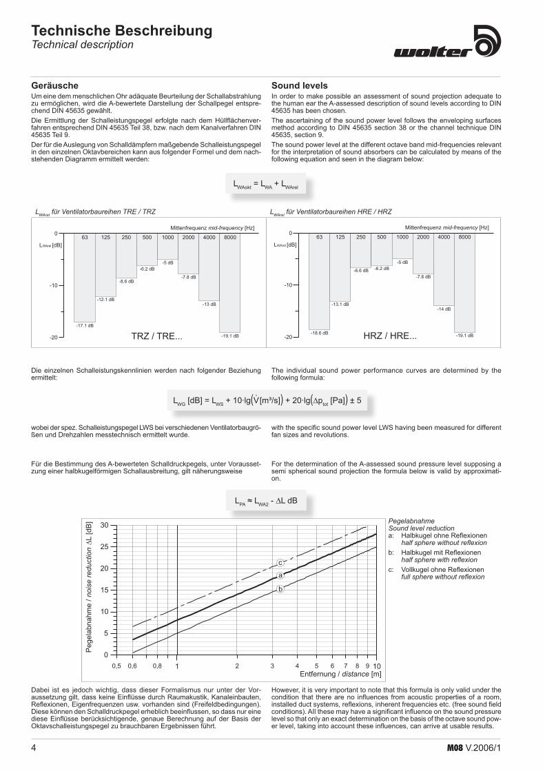
Sound levelsIn order to make possible an assessment of sound projection adequate to the human ear the A-assessed description of sound levels according to DIN 45635 has been chosen.The ascertaining of the sound power level follows the enveloping surfaces method according to DIN 45635 section 38 or the channel technique DIN 45635, section 9.The sound power level at the different octave band mid-frequencies relevant for the interpretation of sound absorbers can be calculated by means of the following equation and seen in the diagram below:
The individual sound power performance curves are determined by the following formula:
with the specific sound power level LWS having been measured for different fan sizes and revolutions.
For the determination of the A-assessed sound pressure level supposing a semi spherical sound projection the formula below is valid by approximati-on.
However, it is very important to note that this formula is only valid under the condition that there are no influences from acoustic properties of a room, installed duct systems, reflexions, inherent frequencies etc. (free sound field conditions). AIl these may have a significant influence on the sound pressure level so that only an exact determination on the basis of the octave sound pow-er level, taking into account these influences, can arrive at usable results.
GeräuscheUm eine dem menschlichen Ohr adäquate Beurteilung der Schallabstrahlung zu ermöglichen, wird die A-bewertete Darstellung der Schallpegel entspre-chend DIN 45635 gewählt.Die Ermittlung der Schalleistungspegel erfolgte nach dem Hüllflächenver-fahren entsprechend DIN 45635 Teil 38, bzw. nach dem Kanalverfahren DIN 45635 Teil 9.Der für die Auslegung von Schalldämpfern maßgebende Schalleistungspegel in den einzelnen Oktavbereichen kann aus folgender Formel und dem nach-stehenden Diagramm ermittelt werden:
Technische BeschreibungTechnical description
LWG [dB] = LWS + 10·lg(V . [m³/s]) + 20·lg(∆ptot [Pa]) ± 5
LWAokt = LWA + LWArel
Die einzelnen Schalleistungskennlinien werden nach folgender Beziehung ermittelt:
wobei der spez. Schalleistungspegel LWS bei verschiedenen Ventilatorbaugrö-ßen und Drehzahlen messtechnisch ermittelt wurde.
LPA ≈ LWA2 - DL dB
Für die Bestimmung des A-bewerteten Schalldruckpegels, unter Vorausset-zung einer halbkugelförmigen Schallausbreitung, gilt näherungsweise
Dabei ist es jedoch wichtig, dass dieser Formalismus nur unter der Vor-aussetzung gilt, dass keine Einflüsse durch Raumakustik, Kanaleinbauten, Reflexionen, Eigenfrequenzen usw. vorhanden sind (Freifeldbedingungen). Diese können den Schalldruckpegel erheblich beeinflussen, so dass nur eine diese Einflüsse berücksichtigende, genaue Berechnung auf der Basis der Oktavschalleistungspegel zu brauchbaren Ergebnissen führt.
LWArel für Ventilatorbaureihen TRE / TRZ LWArel für Ventilatorbaureihen HRE / HRZ
-17.1 dB
-12.1 dB
-8.6 dB
-6.2 dB-5 dB
-7.8 dB
-13 dB
-19.1 dB
63 125 250 500 1000 2000 4000 8000Mittenfrequenz [Hz]mid-frequency
-20
-10
0
LWArel [dB]
T ...RZ / TRE H ...RZ / HRE-18.6 dB
-13.1 dB
-6.6 dB -6.2 dB
-5 dB
-7.8 dB
-14 dB
-19.1 dB
63 125 250 500 1000 2000 4000 8000
Mittenfrequenz [Hz]mid-frequency
-20
-10
0
LWArel [dB]
0,5 0,6 0,8 2 3 4 5 6 7 8 91 10
0
5
10
15
20
25
30
Entfernung / [m]distance
Pegela
bnahm
e/
nois
ere
duct
ion
a
b
L[d
B]
c
Pegelabnahme Sound level reduction
Halbkugel ohne Reflexionen half sphere without reflexionHalbkugel mit Reflexionen half sphere with reflexionVollkugel ohne Reflexionen full sphere without reflexion
a:
b:
c:

5M08 V.2006/1
The performance curves provided in this catalogue were measured according to DIN 24 163 (BS 848) in a test chamber.The sketch below shows the principle set up of the test chamber.
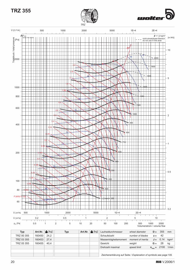
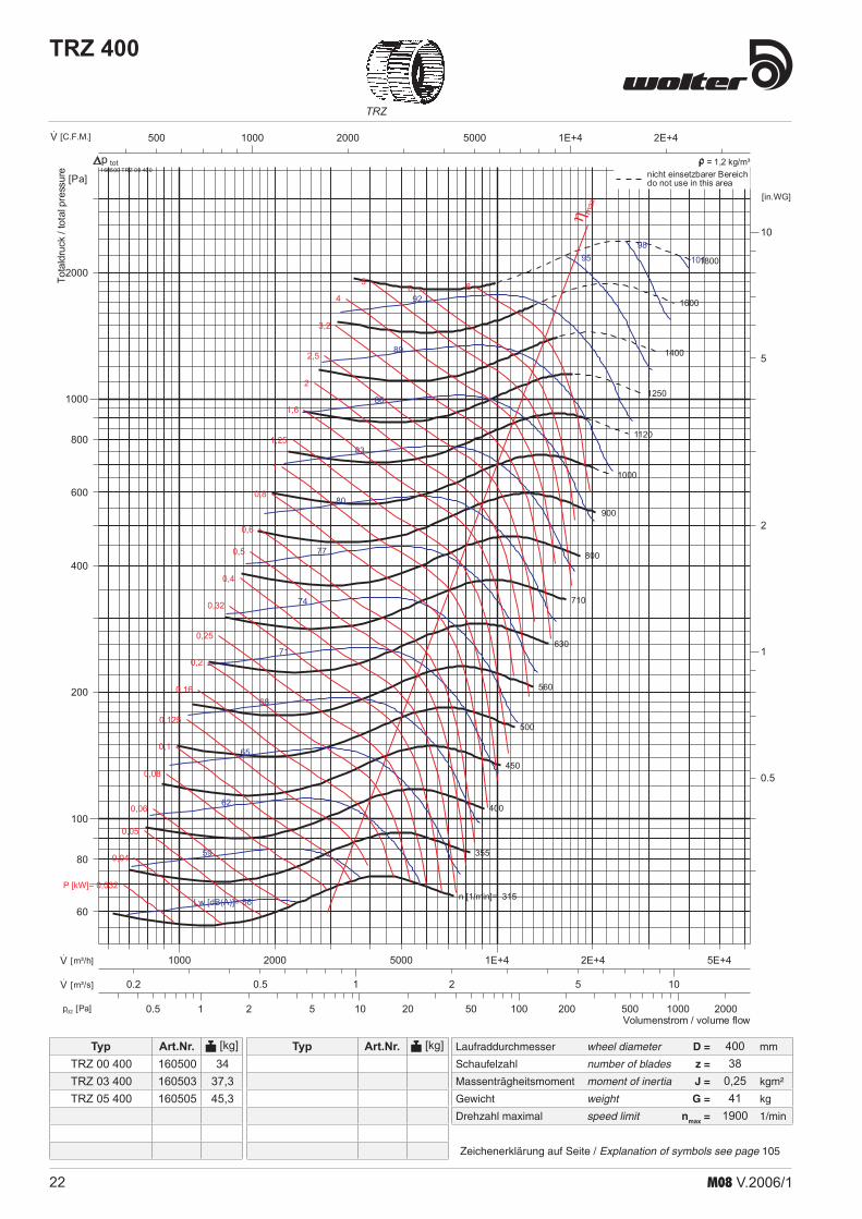
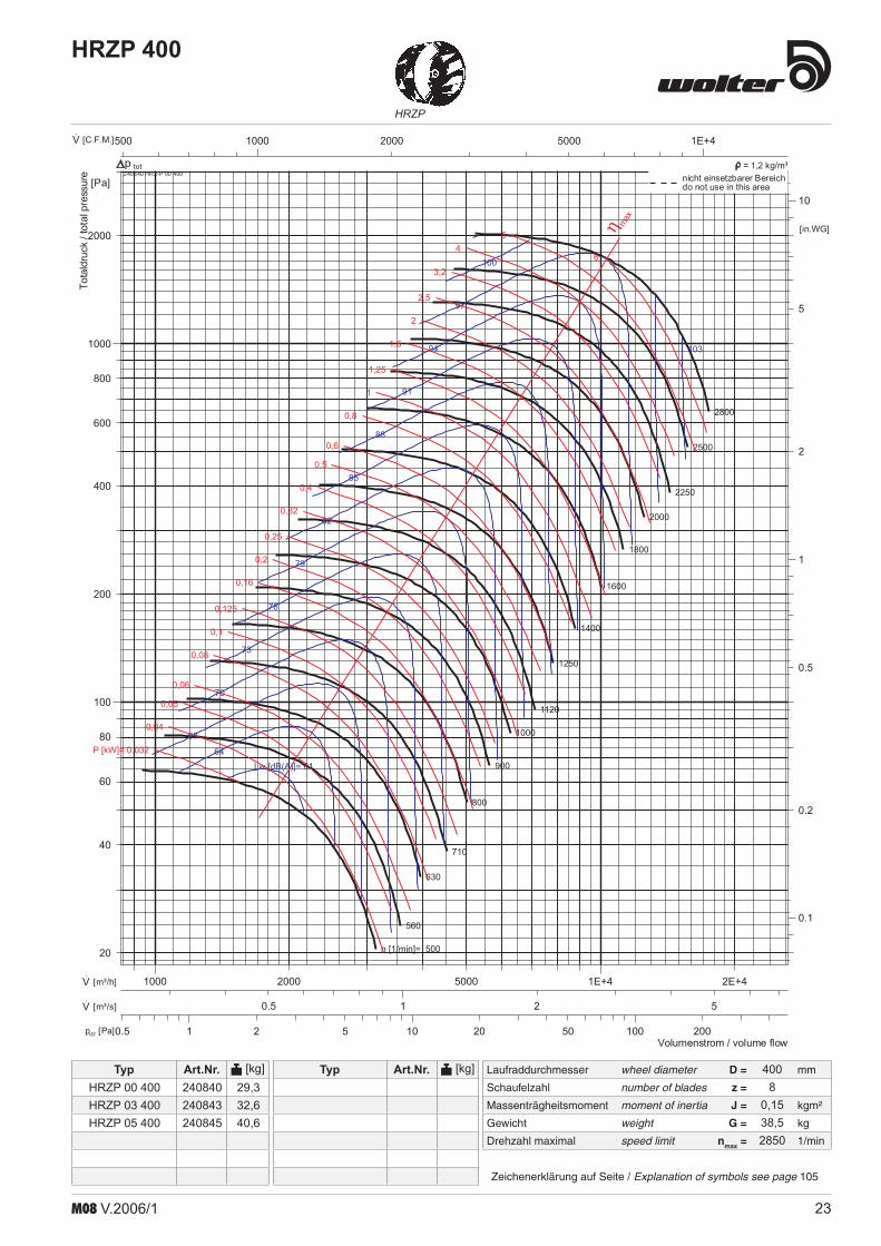
Performance curvesThe performance curves have been established using the inlet test method in the test chamber according to DIN 24 163, mounting position B (free inlet, outlet connected). The curves indicate as a function of the volume flow:
the total pressure increase D ptot. for constant speed(heave black lines)constant lines of shaft power PW (red Lines)constant lines of sound power level LWA (blue lines)
All values relate to an air density:ρ1 = 1,2 kg/m³ at 20°CThe dynamic pressure pd2 and the flow speed c2 respectively stated in the diagrams refer to the flange cross section of the outlet connection pieces.
•••
The acceleration time of the fan can be calculated by the following equati-on:
In case the acceleration time ta is greater than the maximum acceleration time given by the motor manufacturer or the safety switch of the motor reacts during the period of acceleration, then a more powerful motor or a safety switch for heavy-duty acceleration must be used.
200 400 600 800 1000
14
16
18
20
22
kW[%
]
TRZ/TREHRZ/HRE
Baugröße (Laufraddurchmesser) [mm] size (impeller diameter) [mm]
kW = Korrekturfaktor Wellenleistung . . . correction factor for shaft power
ta = Anlaufzeit in s . . . . . . . . . . . . . . . . acceleration time in secondsJ = Massenträgheitsmoment in kg/m² . mass moment of inertia in kg/m²n = Drehzahl des Ventilators in 1/min . nominal speed of the fan in 1/minP = Motorleistung in kW . . . . . . . . . . . . motor rating in kW
Motor powerTo compensate transmission losses when determining the motor rating required it is necessary to increase the shaft performance taken from the performance curve according to the following diagram. By doing so losses at the inlet and V-belt drive as well as mistakes when determining the operation point and possible temperature variations is ac-counted for. Furthermore it must be checked whether the acceleration time of the fan does not exceed the maximum acceleration time of the motor.
1 Inlet nozzle with pressure taps2 Changeover, attachment3 damper with airflow rectifier4 draging riddles5 airflow rectifier6 measuring chamber with door7 pressure display Dpd with pressure taps8 pressure display Dpfa with pressure taps at test item
1 2 3 2 4
5 6
7 8
Die in diesem Katalog abgedruckten Kennlinien wurden auf einem Kammer-prüfstand entsprechend der DIN 24163 gemessen.Die untenstehende Abbildung zeigt den prinzipiellen Aufbau des Prüfstan-des.
Technische BeschreibungTechnical description
KennlinienDie Kennlinien wurden mit einem saugseitigen Kammerprüfstand entsprechend der DIN 24 163 in Einbauart D (frei saugend, druckseitig angeschlossen) aufgenommen. Sie zeigen jeweils als Funktion des Volumenstromes:
die totale Druckerhöhung D ptot für konstante Drehzahlen (dicke schwarze Linien)Konstantenlinie der Wellenleistung PW (rote Linien)Konstantenlinie des Schalleistungspegels LWA (blaue Linien)
Sämtliche Werte beziehen sich auf eine Dichte des Fördermediums von: ρ1 = 1,2 kg/m³ bei 20°CDer in den Diagrammen angegebene dynamische Druck pd2 bzw. die Strö-mungsgeschwindigkeit c2 beziehen sich auf den Flanschquerschnitt des Austrittsstutzens.
•
••
Die Ventilatoranlaufzeit kann mit folgender Formel berechnet werden
Ergibt sich eine Anlaufzeit ta die größer ist als die vom Motorhersteller genannte max. Anlaufzeit oder spricht innerhalb der Anlaufzeit der Motorschutzschal-ter an, muss ein stärkerer Motor bzw. ein Schutzschalter für Schweranlauf eingesetzt werden.
ta = 8 · J · n²
____ P · 10-6
P = PW · (1 + kW ___
100 )
MotorleistungUm die Übertragungsverluste auszugleichen, ist für die Bestimmung der er-forderlichen Motorleistung die aus der Kennlinie abgelesene Wellenleistung entsprechend dem nachfolgenden Diagramm zu erhöhen. Damit sind die Eintrittsverluste, Riemenantriebsverluste, Fehler bei der Betriebspunktbestimmung und eventuelle Temperaturschwankungen be-rücksichtigt.Außerdem muss überprüft werden, ob die Anlaufzeit des Ventilators die max. Anlaufzeit des Motors nicht überschreitet.
1 Einlauf-Meßdüse mit Druckentnahme2 Übergangsstücke, Anschlußstück3 Drosselvorrichtung mit Strömungsgleichrichter4 Bremssiebe5 Strömungsgleichrichter6 Meßkammer mit Türe7 Wirkdruckanzeige Dpd mit Druckentnahmestelle8 Druckanzeige Dpfa mit Druckentnahmestelle Prüfling
6 M08 V.2006/1
Radialventilatoren- keilriemengetrieben- zweiseitig saugend- mit vor- und rückwerts-
gekrümmten Schaufeln
Centrifugal fans- belt driven- double inlet- with backward and forward curved
impellers
KennlinienPerformance curvesTRZ, HRZ, HRZP

7M08 V.2006/1
TRZ
Laufraddurchmesser wheel diameter D = mm
Schaufelzahl number of blades z =
Massenträgheitsmoment moment of inertia J = kgm²
Gewicht weight G = kg
Drehzahl maximal speed limit nmax = 1/min
Typ Art.Nr. [kg]
Zeichenerklärung auf Seite / Explanation of symbols see page 105
Typ Art.Nr. [kg]
TRZ 160
1 10 100 10002 5 20 50 200 500 20000.5pd2 [Pa]
100 1000200 500 2000 5000·V [C.F.M.]
0.1 10.2 0.5 20.05·V [m³/s]
100 1000 1E+4200 500 2000 5000·V [m³/h]
1
10
2
5
0.5
0.2
[in.WG]
100
1000
200
400
600
800
2000
80
60
[Pa]
n [1/min]= 800
900
1000
1120
1250
1400
1600
1800
2000
2250
2500
2800
3150
3550
4000
4500
Lw [dB(A)]= 47
50
53
56
59
62
65
68
71
74
77
80
83
86
8992
P [kW]= 0,005
0,006
0,008
0,01
0,013
0,016
0,02
0,025
0,032
0,04
0,05
0,06
0,08
0,1
0,125
0,16
0,2
0,25
0,32
0,4
0,5
0,6
0,8 1 1,251,6
22,5
3,2 4
η max
Volumenstrom / volume flow
Totaldruck
/totalpressure 160100 TRZ 00 160
totnicht einsetzbarer Bereichdo not use in this area
p = 1,2 kg/m³
TRZ 00 160TRZ 03 160
160100160103
55,6
16036
0,0047
7000

8 M08 V.2006/1
TRZ
Laufraddurchmesser wheel diameter D = mm
Schaufelzahl number of blades z =
Massenträgheitsmoment moment of inertia J = kgm²
Gewicht weight G = kg
Drehzahl maximal speed limit nmax = 1/min
Typ Art.Nr. [kg]
Zeichenerklärung auf Seite / Explanation of symbols see page 105
Typ Art.Nr. [kg]
TRZ 180
1 10 100 10002 5 20 50 200 500 20000.5pd2 [Pa]
100 1000200 500 2000 5000·V [C.F.M.]
0.1 10.2 0.5 20.05·V [m³/s]
1000 1E+42000 5000500200·V [m³/h]
1
10
2
5
0.5
0.2
[in.WG]
100
1000
200
400
600
800
2000
80
60
[Pa]
n [1/min]= 710
800
900
1000
1120
1250
1400
1600
1800
2000
2250
2500
2800
3150
3550
4000
Lw [dB(A)]= 48
51
54
57
60
63
66
69
72
75
78
81
84
87
9093
P [kW]= 0,006
0,008
0,01
0,013
0,016
0,02
0,025
0,032
0,04
0,05
0,06
0,08
0,1
0,125
0,16
0,2
0,25
0,32
0,4
0,5
0,6
0,8
11,25 1,6
22,5
3,24
η max
Volumenstrom / volume flow
Totaldruck
/totalpressure 160150 TRZ 00 180
totnicht einsetzbarer Bereichdo not use in this area
p = 1,2 kg/m³
18040
0,00728,7
4200
TRZ 00 180TRZ 03 180
160150160153
66,8

9M08 V.2006/1
Laufraddurchmesser wheel diameter D = mm
Schaufelzahl number of blades z =
Massenträgheitsmoment moment of inertia J = kgm²
Gewicht weight G = kg
Drehzahl maximal speed limit nmax = 1/min
Typ Art.Nr. [kg]
Zeichenerklärung auf Seite / Explanation of symbols see page 105
Typ Art.Nr. [kg]
HRZP
HRZP 180
1 10 1002 5 20 50 2000.5pd2 [Pa]
100 1000200 500 2000·V [C.F.M.]
0.1 10.2 0.50.05·V [m³/s]
1000 2000500200·V [m³/h]
0.1
1
10
0.2
0.5
2
5
0.05
[in.WG]
10
100
1000
20
40
60
80
200
400
600
800
2000
8
[Pa]
n [1/min]= 1120
1250
1400
1600
1800 2000
2250
2500
28003150
35504000
4500
5000
56006300
Lw [dB(A)]= 51
54
57
60
63
66
69
72
75
78
81
84
87
90
93
P [kW]= 0,006
0,008
0,01
0,013
0,016
0,02
0,025
0,032
0,04
0,05
0,06
0,08
0,1
0,125
0,16
0,2
0,25
0,32
0,4
0,5
0,6
0,8
1
1,25
η max
Volumenstrom / volume flow
Totaldruck
/totalpressure 240140 HRZ-P 00 180
totnicht einsetzbarer Bereichdo not use in this area
p = 1,2 kg/m³
HRZP 00 180HRZP 03 180
240140240143
6,16,9
1808
0,0056,8
7000

10 M08 V.2006/1
TRZ
Laufraddurchmesser wheel diameter D = mm
Schaufelzahl number of blades z =
Massenträgheitsmoment moment of inertia J = kgm²
Gewicht weight G = kg
Drehzahl maximal speed limit nmax = 1/min
Typ Art.Nr. [kg]
Zeichenerklärung auf Seite / Explanation of symbols see page 105
Typ Art.Nr. [kg]
TRZ 200
1 10 100 10002 5 20 50 200 500 20000.5pd2 [Pa]
100 1000200 500 2000 5000·V [C.F.M.]
0.1 10.2 0.5 20.05·V [m³/s]
1000 1E+42000 5000500200·V [m³/h]
1
10
2
5
0.5
0.2
[in.WG]
100
1000
200
400
600
800
2000
80
60
[Pa]
n [1/min]= 630
710
800
900
1000
1120
1250
1400
1600
1800
2000
2250
2500
2800
3150
3550
Lw [dB(A)]= 49
52
55
58
61
64
67
70
73
76
79
82
85
8891
94
P [kW]= 0,008
0,01
0,013
0,016
0,02
0,025
0,032
0,04
0,05
0,06
0,08
0,1
0,125
0,16
0,2
0,25
0,32
0,4
0,5
0,6
0,8
1
1,251,6 2
2,53,2
4
η max
Volumenstrom / volume flow
Totaldruck
/totalpressure 160200 TRZ 00 200
totnicht einsetzbarer Bereichdo not use in this area
p = 1,2 kg/m³
20038
0,019,5
3900
TRZ 00 200TRZ 03 200TRZ 05 200
160200160203160205
7,48,25
10,05
11M08 V.2006/1
Laufraddurchmesser wheel diameter D = mm
Schaufelzahl number of blades z =
Massenträgheitsmoment moment of inertia J = kgm²
Gewicht weight G = kg
Drehzahl maximal speed limit nmax = 1/min
Typ Art.Nr. [kg]
Zeichenerklärung auf Seite / Explanation of symbols see page 105
Typ Art.Nr. [kg]
HRZP
1 10 1002 5 20 50 2000.5pd2 [Pa]
1000 2000500200·V [C.F.M.]
0.1 10.2 0.5·V [m³/s]
1000 2000 5000500200·V [m³/h]
0.1
1
10
0.2
0.5
2
5
[in.WG]
100
1000
200
400
600
800
2000
80
60
40
20
[Pa]
n [1/min]= 1000
1120
1250
1400
1600
1800
2000
2250
2500
2800
3150
3550
4000
4500
5000
5600
Lw [dB(A)]= 53
5659
62
65
68
71
74
77
80
83
86
89
92
95
98
P [kW]= 0,006
0,008
0,01
0,013
0,016
0,02
0,025
0,032
0,04
0,05
0,06
0,08
0,1
0,125
0,16
0,2
0,25
0,32
0,4
0,5
0,6
0,8
1
1,25
η max
Volumenstrom / volume flow
Totaldruck
/totalpressure 240240 HRZ-P 00 200
totnicht einsetzbarer Bereichdo not use in this area
p = 1,2 kg/m³
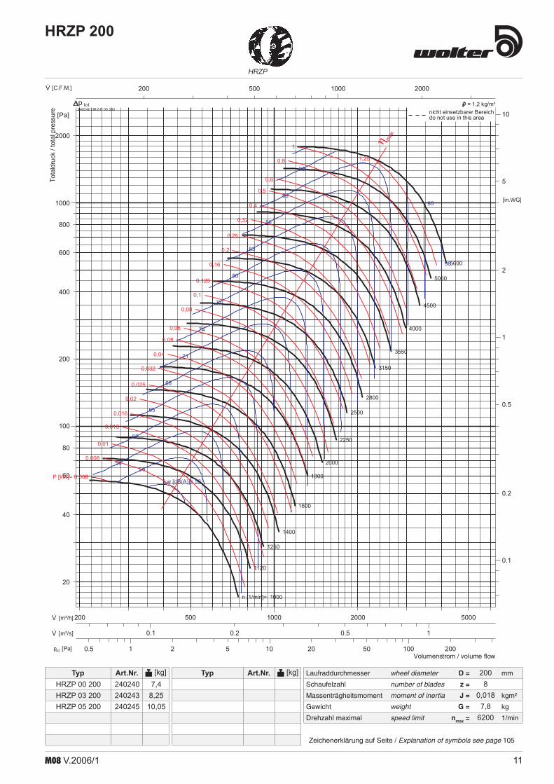
HRZP 200
HRZP 00 200HRZP 03 200HRZP 05 200
240240240243240245
7,48,25
10,05
2008
0,0187,8
6200

12 M08 V.2006/1
TRZ
Laufraddurchmesser wheel diameter D = mm
Schaufelzahl number of blades z =
Massenträgheitsmoment moment of inertia J = kgm²
Gewicht weight G = kg
Drehzahl maximal speed limit nmax = 1/min
Typ Art.Nr. [kg]
Zeichenerklärung auf Seite / Explanation of symbols see page 105
Typ Art.Nr. [kg]
TRZ 225
1 10 100 10002 5 20 50 200 500 20000.5pd2 [Pa]
1000 1E+42000 5000500200·V [C.F.M.]
0.1 10.2 0.5 2 50.05·V [m³/s]
1000 1E+42000 5000500200·V [m³/h]
1
10
2
5
0.5
0.2
[in.WG]
100
1000
200
400
600
800
2000
80
60
[Pa]
n [1/min]= 560
630
710
800
900
1000
1120
1250
1400
1600
1800
2000
2250
2500
2800
3150
Lw [dB(A)]= 50
53
56
59
62
65
68
71
74
77
80
83
86
8992
95
P [kW]= 0,01
0,013
0,016
0,02
0,025
0,032
0,04
0,05
0,06
0,08
0,1
0,125
0,16
0,2
0,25
0,32
0,4
0,5
0,6
0,8
1
1,25
1,62 2,5
3,24
5
η max
Volumenstrom / volume flow
Totaldruck
/totalpressure 160250 TRZ 00 225
totnicht einsetzbarer Bereichdo not use in this area
p = 1,2 kg/m³
22542
0,01912
3400
TRZ 00 225TRZ 03 225TRZ 05 225
160250160253160255
8,89,711,9
13M08 V.2006/1
Laufraddurchmesser wheel diameter D = mm
Schaufelzahl number of blades z =
Massenträgheitsmoment moment of inertia J = kgm²
Gewicht weight G = kg
Drehzahl maximal speed limit nmax = 1/min
Typ Art.Nr. [kg]
Zeichenerklärung auf Seite / Explanation of symbols see page 105
Typ Art.Nr. [kg]
HRZP
HRZP 225
1 10 1002 5 20 50 200 500pd2 [Pa]
1000 2000 5000500200·V [C.F.M.]
0.1 10.2 0.5 2·V [m³/s]
1000 2000 5000500·V [m³/h]
0.1
1
10
0.2
0.5
2
5
[in.WG]
100
1000
200
400
600
800
2000
80
60
40
20
[Pa]
n [1/min]= 1000
1120
1250
1400
1600
1800
2000
2250
2500
2800
3150
3550
4000
4500
5000
5600
Lw [dB(A)]= 57
6063
66
69
72
75
78
81
84
87
90
93
96
99
P [kW]= 0,013
0,016
0,02
0,025
0,032
0,04
0,05
0,06
0,08
0,1
0,125
0,16
0,2
0,25
0,32
0,4
0,5
0,6
0,8
1
1,25
1,62
2,5
η max
Volumenstrom / volume flow
Totaldruck
/totalpressure 240340 HRZ-P 00 225
totnicht einsetzbarer Bereichdo not use in this area
p = 1,2 kg/m³
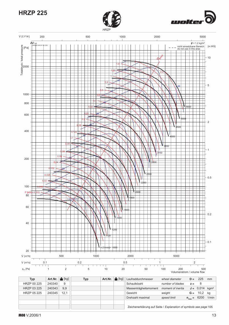
HRZP 00 225HRZP 03 225HRZP 05 225
240340240343240345
99,9
12,1
2258
0,01410,26200

14 M08 V.2006/1
TRZ
Laufraddurchmesser wheel diameter D = mm
Schaufelzahl number of blades z =
Massenträgheitsmoment moment of inertia J = kgm²
Gewicht weight G = kg
Drehzahl maximal speed limit nmax = 1/min
Typ Art.Nr. [kg]
Zeichenerklärung auf Seite / Explanation of symbols see page 105
Typ Art.Nr. [kg]
TRZ 250
1 10 100 10002 5 20 50 200 500 20000.5pd2 [Pa]
1000 1E+42000 5000500200·V [C.F.M.]
0.1 10.2 0.5 2 5·V [m³/s]
1000 1E+42000 5000 2E+4500·V [m³/h]
1
10
2
5
0.5
0.2
[in.WG]
100
1000
200
400
600
800
2000
80
60
[Pa]
n [1/min]= 500
560
630
710
800
900
1000
1120
1250
1400
1600
1800
2000
2250
2500
2800
Lw [dB(A)]= 51
54
57
60
63
66
69
72
75
78
81
84
87
9093
96
P [kW]= 0,01
0,013
0,016
0,02
0,025
0,032
0,04
0,05
0,06
0,08
0,1
0,125
0,16
0,2
0,25
0,32
0,4
0,5
0,6
0,8
1
1,25
1,6 2 2,5 3,24
56
η max
Volumenstrom / volume flow
Totaldruck
/totalpressure 160300 TRZ 00 250
totnicht einsetzbarer Bereichdo not use in this area
p = 1,2 kg/m³
25038
0,0313,83000
TRZ 00 250TRZ 03 250TRZ 05 250
160300160303160305
1112
14,2

15M08 V.2006/1
Laufraddurchmesser wheel diameter D = mm
Schaufelzahl number of blades z =
Massenträgheitsmoment moment of inertia J = kgm²
Gewicht weight G = kg
Drehzahl maximal speed limit nmax = 1/min
Typ Art.Nr. [kg]
Zeichenerklärung auf Seite / Explanation of symbols see page 105
Typ Art.Nr. [kg]
HRZP
HRZP 250
1 10 1002 5 20 50 200 500pd2 [Pa]
1000 2000 5000500·V [C.F.M.]
1 20.50.2·V [m³/s]
1000 1E+42000 5000500·V [m³/h]
0.1
1
10
0.2
0.5
2
5
[in.WG]
100
1000
200
400
600
800
2000
4000
80
60
40
[Pa]
n [1/min]= 1000
1120
1250
1400
1600
1800
2000
2250
2500
2800
3150
3550
4000
4500
5000
5600
Lw [dB(A)]= 60
6366
69
72
75
78
81
84
87
90
93
96
99
102
105
P [kW]= 0,02
0,025
0,032
0,04
0,05
0,06
0,08
0,1
0,125
0,16
0,2
0,25
0,32
0,4
0,5
0,6
0,8
1
1,25
1,6
2
2,5
3,24
η max
Volumenstrom / volume flow
Totaldruck
/totalpressure 240440 HRZ-P 00 250
totnicht einsetzbarer Bereichdo not use in this area
p = 1,2 kg/m³
HRZP 00 250HRZP 03 250HRZP 05 250
240440240443240445
10,511,513,7
2508
0,0212
5800

16 M08 V.2006/1
TRZ
Laufraddurchmesser wheel diameter D = mm
Schaufelzahl number of blades z =
Massenträgheitsmoment moment of inertia J = kgm²
Gewicht weight G = kg
Drehzahl maximal speed limit nmax = 1/min
Typ Art.Nr. [kg]
Zeichenerklärung auf Seite / Explanation of symbols see page 105
Typ Art.Nr. [kg]
TRZ 280
1 10 100 10002 5 20 50 200 500 20000.5pd2 [Pa]
1000 1E+42000 5000500200·V [C.F.M.]
0.1 10.2 0.5 2 5·V [m³/s]
1000 1E+42000 5000 2E+4500·V [m³/h]
1
10
2
5
0.5
0.2
[in.WG]
100
1000
200
400
600
800
2000
80
60
[Pa]
n [1/min]= 450
500
560
630
710
800
900
1000
1120
1250
1400
1600
1800
2000
2250
2500
Lw [dB(A)]= 52
55
58
61
64
67
70
73
76
79
82
85
88
9194
97
P [kW]= 0,013
0,016
0,02
0,025
0,032
0,04
0,05
0,06
0,08
0,1
0,125
0,16
0,2
0,25
0,32
0,4
0,5
0,6
0,8
1
1,25
1,6
2 2,5 3,2 45
68
η max
Volumenstrom / volume flow
Totaldruck/totalpressure 160350 TRZ 00 280
totnicht einsetzbarer Bereichdo not use in this area
p = 1,2 kg/m³
28042
0,05518,52800
TRZ 00 280TRZ 03 280TRZ 05 280
160350160353160355
14,816,720,1

17M08 V.2006/1
Laufraddurchmesser wheel diameter D = mm
Schaufelzahl number of blades z =
Massenträgheitsmoment moment of inertia J = kgm²
Gewicht weight G = kg
Drehzahl maximal speed limit nmax = 1/min
Typ Art.Nr. [kg]
Zeichenerklärung auf Seite / Explanation of symbols see page 105
Typ Art.Nr. [kg]
HRZP
HRZP 280
1 10 1002 5 20 50 200 500pd2 [Pa]
1000 2000 5000500·V [C.F.M.]
1 20.50.2·V [m³/s]
1000 1E+42000 5000500·V [m³/h]
0.1
1
10
0.2
0.5
2
5
[in.WG]
100
1000
200
400
600
800
2000
80
60
40
[Pa]
n [1/min]= 800
900
1000
1120
1250
1400
1600
1800
2000
2250
2500
2800
3150
3550
4000
4500
Lw [dB(A)]= 60
6366
69
72
75
78
81
84
87
90
93
96
99
102
105
P [kW]= 0,02
0,025
0,032
0,04
0,05
0,06
0,08
0,1
0,125
0,16
0,2
0,25
0,32
0,4
0,5
0,6
0,8
1
1,25
1,6
2
2,5
3,2 4
5
η max
Volumenstrom / volume flow
Totaldruck
/totalpressure 240540 HRZ-P 00 280
totnicht einsetzbarer Bereichdo not use in this area
p = 1,2 kg/m³
HRZP 00 280HRZP 03 280HRZP 05 280
240540240543240545
14,416,319,7
2808
0,03416,84700

18 M08 V.2006/1
TRZ
Laufraddurchmesser wheel diameter D = mm
Schaufelzahl number of blades z =
Massenträgheitsmoment moment of inertia J = kgm²
Gewicht weight G = kg
Drehzahl maximal speed limit nmax = 1/min
Typ Art.Nr. [kg]
Zeichenerklärung auf Seite / Explanation of symbols see page 105
Typ Art.Nr. [kg]
TRZ 315
1 10 100 10002 5 20 50 200 500 20000.5pd2 [Pa]
1000 1E+42000 5000 2E+4500·V [C.F.M.]
0.1 1 100.2 0.5 2 5·V [m³/s]
1000 1E+42000 5000 2E+4500·V [m³/h]
1
10
2
5
0.5
0.2
[in.WG]
100
1000
200
400
600
800
2000
80
60
[Pa]
n [1/min]= 400
450
500
560
630
710
800
900
1000
1120
1250
1400
1600
1800
2000
2250
Lw [dB(A)]= 53
56
59
62
65
68
71
74
77
80
83
86
89
92
9598
P [kW]= 0,016
0,02
0,025
0,032
0,04
0,05
0,06
0,08
0,1
0,125
0,16
0,2
0,25
0,32
0,4
0,5
0,6
0,8
1
1,25
1,6
2
2,53,2 4 5
6
8
η max
Volumenstrom / volume flow
Totaldruck/totalpressure 160400 TRZ 00 315
totnicht einsetzbarer Bereichdo not use in this area
p = 1,2 kg/m³
31538
0,0822,52400
TRZ 00 315TRZ 03 315TRZ 05 315
160400160403160405
18,420,4525,45

19M08 V.2006/1
Laufraddurchmesser wheel diameter D = mm
Schaufelzahl number of blades z =
Massenträgheitsmoment moment of inertia J = kgm²
Gewicht weight G = kg
Drehzahl maximal speed limit nmax = 1/min
Typ Art.Nr. [kg]
Zeichenerklärung auf Seite / Explanation of symbols see page 105
Typ Art.Nr. [kg]
HRZP
HRZP 315
1 10 1002 5 20 50 2000.5pd2 [Pa]
1000 2000 5000500·V [C.F.M.]
1 20.50.2·V [m³/s]
1000 1E+42000 5000·V [m³/h]
0.1
1
10
0.2
0.5
2
5
[in.WG]
100
1000
200
400
600
800
2000
80
60
40
20
[Pa]
n [1/min]= 630
710
800
900
1000
1120
1250
1400
1600
1800
2000
2250
2500
2800
3150
3550
Lw [dB(A)]= 5962
65
68
71
74
77
80
83
86
89
92
95
98
101
P [kW]= 0,02
0,025
0,032
0,04
0,05
0,06
0,08
0,1
0,125
0,16
0,2
0,25
0,32
0,4
0,5
0,6
0,8
1
1,25
1,6
2
2,53,2
4
η max
Volumenstrom / volume flow
Totaldruck/totalpressure 240640 HRZ-P 00 315
totnicht einsetzbarer Bereichdo not use in this area
p = 1,2 kg/m³
3158
0,0521
3700
HRZP 00 315HRZP 03 315HRZP 05 315
240640240643240645
1820,0525,05
20 M08 V.2006/1
TRZ
Laufraddurchmesser wheel diameter D = mm
Schaufelzahl number of blades z =
Massenträgheitsmoment moment of inertia J = kgm²
Gewicht weight G = kg
Drehzahl maximal speed limit nmax = 1/min
Typ Art.Nr. [kg]
Zeichenerklärung auf Seite / Explanation of symbols see page 105
Typ Art.Nr. [kg]
TRZ 355
1 10 100 10002 5 20 50 200 500 20000.5pd2 [Pa]
1000 1E+42000 5000 2E+4500·V [C.F.M.]
1 102 50.50.2·V [m³/s]
1000 1E+42000 5000 2E+4500·V [m³/h]
1
10
2
5
0.5
0.2
[in.WG]
100
1000
200
400
600
800
2000
80
60
[Pa]
n [1/min]= 355
400
450
500
560
630
710
800
900
1000
1120
1250
1400
1600
1800
2000
Lw [dB(A)]= 55
58
61
64
67
70
73
76
79
82
85
88
91
9497
P [kW]= 0,025
0,032
0,04
0,05
0,06
0,08
0,1
0,125
0,16
0,2
0,25
0,32
0,4
0,5
0,6
0,8
1
1,25
1,6
2
2,5
3,24 5 6
8
η max
Volumenstrom / volume flow
Totaldruck/totalpressure 160450 TRZ 00 355
totnicht einsetzbarer Bereichdo not use in this area
p = 1,2 kg/m³
TRZ 00 355TRZ 03 355TRZ 05 355
160450160453160455
24,227,440,4
35542
0,1428
2100

21M08 V.2006/1
Laufraddurchmesser wheel diameter D = mm
Schaufelzahl number of blades z =
Massenträgheitsmoment moment of inertia J = kgm²
Gewicht weight G = kg
Drehzahl maximal speed limit nmax = 1/min
Typ Art.Nr. [kg]
Zeichenerklärung auf Seite / Explanation of symbols see page 105
Typ Art.Nr. [kg]
HRZP
HRZP 355
1 10 1002 5 20 50 200 5000.5pd2 [Pa]
1000 1E+42000 5000500·V [C.F.M.]
1 2 50.50.2·V [m³/s]
1000 1E+42000 5000 2E+4·V [m³/h]
0.1
1
10
0.2
0.5
2
5
[in.WG]
100
1000
200
400
600
800
2000
80
60
40
20
[Pa]
n [1/min]= 560
630
710
800
900
1000
1120
1250
1400
1600
1800
2000
2250
2500
2800
3150
Lw [dB(A)]= 60
6366
69
72
75
78
81
84
87
90
93
96
99
102
P [kW]= 0,025
0,032
0,04
0,05
0,06
0,08
0,1
0,125
0,16
0,2
0,25
0,32
0,4
0,5
0,6
0,8
1
1,25
1,6
2
2,5
3,24
5
η max
Volumenstrom / volume flow
Totaldruck/totalpressure 240740 HRZ-P 00 355
totnicht einsetzbarer Bereichdo not use in this area
p = 1,2 kg/m³
3558
0,126,53400
HRZP 00 355HRZP 03 355HRZP 05 355
240740240743240745
24,127,340,5
22 M08 V.2006/1
TRZ
Laufraddurchmesser wheel diameter D = mm
Schaufelzahl number of blades z =
Massenträgheitsmoment moment of inertia J = kgm²
Gewicht weight G = kg
Drehzahl maximal speed limit nmax = 1/min
Typ Art.Nr. [kg]
Zeichenerklärung auf Seite / Explanation of symbols see page 105
Typ Art.Nr. [kg]
TRZ 400
1 10 100 10002 5 20 50 200 500 20000.5pd2 [Pa]
1000 1E+42000 5000 2E+4500·V [C.F.M.]
1 102 50.50.2·V [m³/s]
1000 1E+42000 5000 2E+4 5E+4·V [m³/h]
1
10
2
5
0.5
[in.WG]
100
1000
200
400
600
800
2000
80
60
[Pa]
n [1/min]= 315
355
400
450
500
560
630
710
800
900
1000
1120
1250
1400
1600
1800
Lw [dB(A)]= 56
59
62
65
68
71
74
77
80
83
86
89
92
9598
101
P [kW]= 0,032
0,04
0,05
0,06
0,08
0,1
0,125
0,16
0,2
0,25
0,32
0,4
0,5
0,6
0,8
1
1,25
1,6
2
2,5
3,2
4
56 8
η max
Volumenstrom / volume flow
Totaldruck
/totalpressure 160500 TRZ 00 400
totnicht einsetzbarer Bereichdo not use in this area
p = 1,2 kg/m³
TRZ 00 400TRZ 03 400TRZ 05 400
160500160503160505
3437,345,3
40038
0,2541
1900
23M08 V.2006/1
Laufraddurchmesser wheel diameter D = mm
Schaufelzahl number of blades z =
Massenträgheitsmoment moment of inertia J = kgm²
Gewicht weight G = kg
Drehzahl maximal speed limit nmax = 1/min
Typ Art.Nr. [kg]
Zeichenerklärung auf Seite / Explanation of symbols see page 105
Typ Art.Nr. [kg]
HRZP
HRZP 400
1 10 1002 5 20 50 2000.5pd2 [Pa]
1000 1E+42000 5000500·V [C.F.M.]
1 2 50.5·V [m³/s]
1000 1E+42000 5000 2E+4·V [m³/h]
0.1
1
10
0.2
0.5
2
5
[in.WG]
100
1000
200
400
600
800
2000
80
60
40
20
[Pa]
n [1/min]= 500
560
630
710
800
900
1000
1120
1250
1400
1600
1800
2000
2250
2500
2800
Lw [dB(A)]= 6164
67
70
73
76
79
82
85
88
91
94
97
100
103
P [kW]= 0,032
0,04
0,05
0,06
0,08
0,1
0,125
0,16
0,2
0,25
0,32
0,4
0,5
0,6
0,8
1
1,25
1,6
2
2,5
3,2
45
6
η max
Volumenstrom / volume flow
Totaldruck
/totalpressure 240840 HRZ-P 00 400
totnicht einsetzbarer Bereichdo not use in this area
p = 1,2 kg/m³
4008
0,1538,52850
HRZP 00 400HRZP 03 400HRZP 05 400
240840240843240845
29,332,640,6

24 M08 V.2006/1
TRZ
Laufraddurchmesser wheel diameter D = mm
Schaufelzahl number of blades z =
Massenträgheitsmoment moment of inertia J = kgm²
Gewicht weight G = kg
Drehzahl maximal speed limit nmax = 1/min
Typ Art.Nr. [kg]
Zeichenerklärung auf Seite / Explanation of symbols see page 105
Typ Art.Nr. [kg]
TRZ 450
1 10 100 10002 5 20 50 200 500 20000.5pd2 [Pa]
1000 1E+42000 5000 2E+4500·V [C.F.M.]
1 102 5 200.50.2·V [m³/s]
1000 1E+42000 5000 2E+4 5E+4·V [m³/h]
1
10
2
5
0.5
[in.WG]
100
1000
200
400
600
800
2000
80
60
[Pa]
n [1/min]= 280
315
355
400
450
500
560
630
710
800
900
1000
1120
1250
1400
1600
Lw [dB(A)]= 57
60
63
66
69
72
75
78
81
84
87
90
93
9699
102
P [kW]= 0,032
0,04
0,05
0,06
0,08
0,1
0,125
0,16
0,2
0,25
0,32
0,4
0,5
0,6
0,8
1
1,25
1,6
2
2,5
3,2
4
5
68 10
η max
Volumenstrom / volume flow
Totaldruck
/totalpressure 160550 TRZ 00 450
totnicht einsetzbarer Bereichdo not use in this area
p = 1,2 kg/m³
TRZ 00 450TRZ 03 450TRZ 05 450
160550160553160555
44,849,8558,25
45042
0,37549
1700

25M08 V.2006/1
Laufraddurchmesser wheel diameter D = mm
Schaufelzahl number of blades z =
Massenträgheitsmoment moment of inertia J = kgm²
Gewicht weight G = kg
Drehzahl maximal speed limit nmax = 1/min
Typ Art.Nr. [kg]
Zeichenerklärung auf Seite / Explanation of symbols see page 105
Typ Art.Nr. [kg]
HRZP
HRZP 450
1 10 1002 5 20 50 200pd2 [Pa]
1000 1E+42000 5000·V [C.F.M.]
1 2 50.5·V [m³/s]
1E+4 2E+450002000·V [m³/h]
0.1
1
10
0.2
0.5
2
5
[in.WG]
100
1000
200
400
600
800
2000
80
60
40
20
[Pa]
n [1/min]= 450
500
560
630
710
800
900
1000
1120
1250
1400
1600
1800
2000
2250
2500
Lw [dB(A)]= 62
6568
71
74
77
80
83
86
89
92
95
98
101
104
P [kW]= 0,04
0,05
0,06
0,08
0,1
0,125
0,16
0,2
0,25
0,32
0,4
0,5
0,6
0,8
1
1,25
1,6
2
2,5
3,2
4
5
6
8
η max
Volumenstrom / volume flow
Totaldruck
/totalpressure 240940 HRZ-P 00 450
totnicht einsetzbarer Bereichdo not use in this area
p = 1,2 kg/m³
4508
0,5345
2500
HRZP 00 450HRZP 03 450HRZP 05 450
240940240943240945
4045,0553,45

26 M08 V.2006/1
TRZ
Laufraddurchmesser wheel diameter D = mm
Schaufelzahl number of blades z =
Massenträgheitsmoment moment of inertia J = kgm²
Gewicht weight G = kg
Drehzahl maximal speed limit nmax = 1/min
Typ Art.Nr. [kg]
Zeichenerklärung auf Seite / Explanation of symbols see page 105
Typ Art.Nr. [kg]
TRZ 500
1 10 100 10002 5 20 50 200 500 20000.5pd2 [Pa]
1000 1E+42000 5000 2E+4 5E+4·V [C.F.M.]
1 102 5 200.5·V [m³/s]
1000 1E+42000 5000 2E+4 5E+4·V [m³/h]
1
10
2
5
0.5
[in.WG]
100
1000
200
400
600
800
2000
80
60
[Pa]
n [1/min]= 250
280
315
355
400
450
500
560
630
710
800
900
1000
1120
1250
1400
Lw [dB(A)]= 58
61
64
67
70
73
76
79
82
85
88
91
94
97100
P [kW]= 0,04
0,05
0,06
0,08
0,1
0,125
0,16
0,2
0,25
0,32
0,4
0,5
0,6
0,8
1
1,25
1,6
2
2,5
3,2
4
5
6 8 10
η max
Volumenstrom / volume flow
Totaldruck
/totalpressure 160600 TRZ 00 500
totnicht einsetzbarer Bereichdo not use in this area
p = 1,2 kg/m³
TRZ 00 500TRZ 03 500TRZ 05 500
160600160603160605
59,264,484,8
500380,863
1500

27M08 V.2006/1
Laufraddurchmesser wheel diameter D = mm
Schaufelzahl number of blades z =
Massenträgheitsmoment moment of inertia J = kgm²
Gewicht weight G = kg
Drehzahl maximal speed limit nmax = 1/min
Typ Art.Nr. [kg]
Zeichenerklärung auf Seite / Explanation of symbols see page 105
Typ Art.Nr. [kg]
HRZ
HRZ 500
1 10 100 10002 5 20 50 200 5000.50.2pd2 [Pa]
1000 1E+42000 5000 2E+4500·V [C.F.M.]
1 102 50.50.2·V [m³/s]
1000 1E+42000 5000 2E+4 5E+4·V [m³/h]
1
10
2
5
20
0.5
0.2
[in.WG]
100
1000
200
400
600
800
2000
4000
80
60
40
[Pa]
n [1/min]= 500
560
630
710
800
900
1000
1120
1250
1400
1600
1800
2000
2250
2500
2800
Lw [dB(A)]= 62
65
68
71
74
77
80
83
86
89
92
95
98
101
104
107
P [kW]= 0,04
0,05
0,06
0,08
0,1
0,125
0,16
0,2
0,25
0,32
0,4
0,5
0,6
0,8
1
1,25
1,6
2
2,5
3,2
4
5
6 8 10 12,5 16 20
η max
Volumenstrom / volume flow
Totaldruck
/totalpressure 240600 HRZ 00 500
totnicht einsetzbarer Bereichdo not use in this area
p = 1,2 kg/m³
50010
0,55257
2800
HRZ 00 500HRZ 03 500HRZ 05 500
240600240603240605
49,454,675

28 M08 V.2006/1
TRZ
Laufraddurchmesser wheel diameter D = mm
Schaufelzahl number of blades z =
Massenträgheitsmoment moment of inertia J = kgm²
Gewicht weight G = kg
Drehzahl maximal speed limit nmax = 1/min
Typ Art.Nr. [kg]
Zeichenerklärung auf Seite / Explanation of symbols see page 105
Typ Art.Nr. [kg]
TRZ 560
1 10 100 10002 5 20 50 200 5000.50.2pd2 [Pa]
1000 1E+42000 5000 2E+4 5E+4·V [C.F.M.]
1 102 5 200.5·V [m³/s]
1000 1E+4 1E+52000 5000 2E+4 5E+4·V [m³/h]
1
10
2
5
0.5
0.2
[in.WG]
100
1000
200
400
600
800
2000
80
60
[Pa]
n [1/min]= 200
225
250
280
315
355
400
450
500
560
630
710
800
900
1000
1120
Lw [dB(A)]= 56
59
62
65
68
71
74
77
80
83
86
89
92
9598
101
P [kW]= 0,04
0,05
0,06
0,08
0,1
0,125
0,16
0,2
0,25
0,32
0,4
0,5
0,6
0,8
1
1,25
1,6
2
2,5
3,2
4
5
68 10
12,5
η max
Volumenstrom / volume flow
Totaldruck
/totalpressure 160650 TRZ 00 560
totnicht einsetzbarer Bereichdo not use in this area
p = 1,2 kg/m³
TRZ 00 560TRZ 03 560TRZ 05 560
160650160653160655
74,681,9
104,9
56042
1,3382
1200

29M08 V.2006/1
Laufraddurchmesser wheel diameter D = mm
Schaufelzahl number of blades z =
Massenträgheitsmoment moment of inertia J = kgm²
Gewicht weight G = kg
Drehzahl maximal speed limit nmax = 1/min
Typ Art.Nr. [kg]
Zeichenerklärung auf Seite / Explanation of symbols see page 105
Typ Art.Nr. [kg]
HRZ
HRZ 560
1 10 100 10002 5 20 50 200 5000.50.2pd2 [Pa]
1000 1E+42000 5000 2E+4·V [C.F.M.]
1 102 5 200.5·V [m³/s]
1000 1E+42000 5000 2E+4 5E+4·V [m³/h]
1
10
2
5
20
0.5
0.2
[in.WG]
100
1000
200
400
600
800
2000
4000
80
60
40
[Pa]
n [1/min]= 450
500
560
630
710
800
900
1000
1120
1250
1400
1600
1800
2000
2250
2500
Lw [dB(A)]= 64
67
70
73
76
79
82
85
88
91
94
97
100
103
106
109
P [kW]= 0,05
0,06
0,08
0,1
0,125
0,16
0,2
0,25
0,32
0,4
0,5
0,6
0,8
1
1,25
1,6
2
2,5
3,2
4
5
6
8 10 12,5 16 20 25
η max
Volumenstrom / volume flow
Totaldruck
/totalpressure 240650 HRZ 00 560
totnicht einsetzbarer Bereichdo not use in this area
p = 1,2 kg/m³
56010
1,11673
2500
HRZ 00 560HRZ 03 560HRZ 05 560
240650240653240655
677391

30 M08 V.2006/1
TRZ
Laufraddurchmesser wheel diameter D = mm
Schaufelzahl number of blades z =
Massenträgheitsmoment moment of inertia J = kgm²
Gewicht weight G = kg
Drehzahl maximal speed limit nmax = 1/min
Typ Art.Nr. [kg]
Zeichenerklärung auf Seite / Explanation of symbols see page 105
Typ Art.Nr. [kg]
TRZ 630
1 10 100 10002 5 20 50 200 5000.50.2pd2 [Pa]
1000 1E+42000 5000 2E+4 5E+4·V [C.F.M.]
1 102 5 200.5·V [m³/s]
1E+4 1E+52E+4 5E+450002000·V [m³/h]
1
2
5
0.5
0.2
[in.WG]
100
1000
200
400
600
800
2000
80
60
40
[Pa]
n [1/min]= 160
180
200
225
250
280
315
355
400
450
500
560
630
710
800
900
Lw [dB(A)]= 55
58
61
64
67
70
73
76
79
82
85
88
91
9497
100
P [kW]= 0,032
0,04
0,05
0,06
0,08
0,1
0,125
0,16
0,2
0,25
0,32
0,4
0,5
0,6
0,8
1
1,25
1,6
2
2,5
3,2
4
56
8 1012,5
η max
Volumenstrom / volume flow
Totaldruck
/totalpressure 160700 TRZ 00 630
totnicht einsetzbarer Bereichdo not use in this area
p = 1,2 kg/m³
TRZ 00 630TRZ 03 630TRZ 05 630
160700160703160705
97,4104,5126
630382,3105950

31M08 V.2006/1
Laufraddurchmesser wheel diameter D = mm
Schaufelzahl number of blades z =
Massenträgheitsmoment moment of inertia J = kgm²
Gewicht weight G = kg
Drehzahl maximal speed limit nmax = 1/min
Typ Art.Nr. [kg]
Zeichenerklärung auf Seite / Explanation of symbols see page 105
Typ Art.Nr. [kg]
HRZ
HRZ 630
1 10 1002 5 20 50 200 5000.50.2pd2 [Pa]
1000 1E+42000 5000 2E+4 5E+4·V [C.F.M.]
1 102 5 200.5·V [m³/s]
1E+4 2E+4 5E+450002000·V [m³/h]
1
10
2
5
20
0.5
0.2
[in.WG]
100
1000
200
400
600
800
2000
4000
80
60
40
[Pa]
n [1/min]= 400
450
500
560
630
710
800
900
1000
1120
1250
1400
1600
1800
2000
2250
Lw [dB(A)]= 65
68
71
74
77
80
83
86
89
92
95
98
101
104
107
110
P [kW]= 0,06
0,08
0,1
0,125
0,16
0,2
0,25
0,32
0,4
0,5
0,6
0,8
1
1,25
1,6
2
2,5
3,2
4
5
6
8
1012,5 16 20 25 η m
ax
Volumenstrom / volume flow
Totaldruck
/totalpressure 240700 HRZ 00 630
totnicht einsetzbarer Bereichdo not use in this area
p = 1,2 kg/m³
63010
1,6196
2200
HRZ 00 630HRZ 03 630HRZ 05 630
240700240703240705
82,689,7111,2

32 M08 V.2006/1
TRZ
Laufraddurchmesser wheel diameter D = mm
Schaufelzahl number of blades z =
Massenträgheitsmoment moment of inertia J = kgm²
Gewicht weight G = kg
Drehzahl maximal speed limit nmax = 1/min
Typ Art.Nr. [kg]
Zeichenerklärung auf Seite / Explanation of symbols see page 105
Typ Art.Nr. [kg]
TRZ 71000-05
1 10 100 10002 5 20 50 200 5000.50.2pd2 [Pa]
1000 1E+42000 5000 2E+4 5E+4·V [C.F.M.]
1 102 5 200.5·V [m³/s]
1E+4 1E+52E+4 5E+450002000·V [m³/h]
1
2
5
0.5
0.2
[in.WG]
100
1000
200
400
600
800
80
60
40
[Pa]
n [1/min]= 125
140
160
180
200
225
250
280
315
355
400
450
500
560
630
710
Lw [dB(A)]= 53
56
59
62
65
68
71
74
77
80
83
86
89
92
9598
P [kW]= 0,032
0,04
0,05
0,06
0,08
0,1
0,125
0,16
0,2
0,25
0,32
0,4
0,5
0,6
0,8
1
1,25
1,6
2
2,5
3,2
4
56 8
1012,5
η max
Volumenstrom / volume flow
Totaldruck
/totalpressure 160750 TRZ 00 710
totnicht einsetzbarer Bereichdo not use in this area
p = 1,2 kg/m³
TRZ 00 710TRZ 03 710TRZ 05 710TRZ 07 710
160750160753160755160757
0000
71042
3,75152750

33M08 V.2006/1
Laufraddurchmesser wheel diameter D = mm
Schaufelzahl number of blades z =
Massenträgheitsmoment moment of inertia J = kgm²
Gewicht weight G = kg
Drehzahl maximal speed limit nmax = 1/min
Typ Art.Nr. [kg]
Zeichenerklärung auf Seite / Explanation of symbols see page 105
Typ Art.Nr. [kg]
HRZ
HRZ 71000-05
0.1 1 10 1000.2 0.5 2 5 20 50 200 500pd2 [Pa]
1000 1E+42000 5000 2E+4 5E+4·V [C.F.M.]
1 102 5 200.5·V [m³/s]
1E+4 2E+4 5E+450002000·V [m³/h]
0.1
1
10
0.2
0.5
2
5[in.WG]
100
1000
200
400
600
800
2000
80
60
40
20
[Pa]
n [1/min]= 250
280
315
355
400
450
500
560
630
710
800
900
1000
1120
1250
1400
Lw [dB(A)]= 58
61
64
67
70
73
76
79
82
85
88
91
94
97
100
103
P [kW]= 0,032
0,04
0,05
0,06
0,08
0,1
0,125
0,16
0,2
0,25
0,32
0,4
0,5
0,6
0,8
1
1,25
1,6
2
2,5
3,2
4
5 6 8 10 12,5
16
η max
Volumenstrom / volume flow
Totaldruck
/totalpressure 240750 HRZ 00 710
totnicht einsetzbarer Bereichdo not use in this area
p = 1,2 kg/m³
71010
2,625139
1400
HRZ 00 710HRZ 03 710HRZ 05 710HRZ 07 710
240750240753240755240757
135139163165

34 M08 V.2006/1
TRZ
Laufraddurchmesser wheel diameter D = mm
Schaufelzahl number of blades z =
Massenträgheitsmoment moment of inertia J = kgm²
Gewicht weight G = kg
Drehzahl maximal speed limit nmax = 1/min
Typ Art.Nr. [kg]
Zeichenerklärung auf Seite / Explanation of symbols see page 105
Typ Art.Nr. [kg]
TRZ 71006-07
1 10 100 10002 5 20 50 200 5000.50.2pd2 [Pa]
1000 1E+42000 5000 2E+4 5E+4·V [C.F.M.]
1 102 5 200.5·V [m³/s]
1E+4 1E+52E+4 5E+450002000·V [m³/h]
1
2
5
0.5
0.2
[in.WG]
100
1000
200
400
600
800
2000
80
60
40
[Pa]
n [1/min]= 140
160
180
200
225
250
280
315
355
400
450
500
560
630
710
800
Lw [dB(A)]= 56
59
62
65
68
71
74
77
80
83
86
89
92
9598
101
P [kW]= 0,04
0,05
0,06
0,08
0,1
0,125
0,16
0,2
0,25
0,32
0,4
0,5
0,6
0,8
1
1,25
1,6
2
2,5
3,2
4
5
6
8 10 12,516
20
η max
Volumenstrom / volume flow
Totaldruck
/totalpressure 160757 TRZ 07 710
totnicht einsetzbarer Bereichdo not use in this area
p = 1,2 kg/m³
TRZ 00 710TRZ 03 710TRZ 05 710TRZ 07 710
160750160753160755160757
0000
71042
3,75204850

35M08 V.2006/1
Laufraddurchmesser wheel diameter D = mm
Schaufelzahl number of blades z =
Massenträgheitsmoment moment of inertia J = kgm²
Gewicht weight G = kg
Drehzahl maximal speed limit nmax = 1/min
Typ Art.Nr. [kg]
Zeichenerklärung auf Seite / Explanation of symbols see page 105
Typ Art.Nr. [kg]
HRZ
HRZ 71006-07
0.1 1 10 1000.2 0.5 2 5 20 50 200 500pd2 [Pa]
1000 1E+42000 5000 2E+4 5E+4·V [C.F.M.]
1 102 5 200.5·V [m³/s]
1E+4 2E+4 5E+450002000·V [m³/h]
0.1
1
10
0.2
0.5
2
5[in.WG]
100
1000
200
400
600
800
2000
80
60
40
[Pa]
n [1/min]= 280
315
355
400
450
500
560
630
710
800
900
1000
1120
1250
1400
1600
Lw [dB(A)]= 61
64
67
70
73
76
79
82
85
88
91
94
97
100
103
106
P [kW]= 0,04
0,05
0,06
0,08
0,1
0,125
0,16
0,2
0,25
0,32
0,4
0,5
0,6
0,8
1
1,25
1,6
2
2,5
3,2
4
5
6
8 10 12,5 16 20 η max
Volumenstrom / volume flow
Totaldruck
/totalpressure 240757 HRZ 07 710
totnicht einsetzbarer Bereichdo not use in this area
p = 1,2 kg/m³
71010
2,625165
1600
HRZ 00 710HRZ 03 710HRZ 05 710HRZ 07 710
240750240753240755240757
135139163165

36 M08 V.2006/1
TRZ
Laufraddurchmesser wheel diameter D = mm
Schaufelzahl number of blades z =
Massenträgheitsmoment moment of inertia J = kgm²
Gewicht weight G = kg
Drehzahl maximal speed limit nmax = 1/min
Typ Art.Nr. [kg]
Zeichenerklärung auf Seite / Explanation of symbols see page 105
Typ Art.Nr. [kg]
TRZ 800
1 10 100 10002 5 20 50 200 5000.50.2pd2 [Pa]
1E+4 1E+52E+4 5E+450002000·V [C.F.M.]
1 102 5 20 500.5·V [m³/s]
1E+4 1E+52E+4 5E+450002000·V [m³/h]
1
2
5
0.5
0.2
[in.WG]
100
1000
200
400
600
800
2000
80
60
40
[Pa]
n [1/min]= 125
140
160
180
200
225
250
280
315
355
400
450
500
560
630
710
Lw [dB(A)]= 57
60
63
66
69
72
75
78
81
84
87
90
93
9699
102
P [kW]= 0,05
0,06
0,08
0,1
0,125
0,16
0,2
0,25
0,32
0,4
0,5
0,6
0,8
1
1,25
1,6
2
2,5
3,2
4
5
6
810 12,5 16
2025
η max
Volumenstrom / volume flow
Totaldruck
/totalpressure 160807 TRZ 07 800
totnicht einsetzbarer Bereichdo not use in this area
p = 1,2 kg/m³
TRZ 07 800 160807 080038
5,63254750

37M08 V.2006/1
Laufraddurchmesser wheel diameter D = mm
Schaufelzahl number of blades z =
Massenträgheitsmoment moment of inertia J = kgm²
Gewicht weight G = kg
Drehzahl maximal speed limit nmax = 1/min
Typ Art.Nr. [kg]
Zeichenerklärung auf Seite / Explanation of symbols see page 105
Typ Art.Nr. [kg]
HRZ
HRZ 800
0.1 1 10 1000.2 0.5 2 5 20 50 200 500pd2 [Pa]
1000 1E+42000 5000 2E+4 5E+4·V [C.F.M.]
1 102 5 200.5·V [m³/s]
1E+4 1E+52E+4 5E+450002000·V [m³/h]
0.1
1
10
0.2
0.5
2
5
[in.WG]
100
1000
200
400
600
800
2000
80
60
40
[Pa]
n [1/min]= 250
280
315
355
400
450
500
560
630
710
800
900
1000
1120
1250
1400
Lw [dB(A)]= 62
65
68
71
74
77
80
83
86
89
92
95
98
101
104
107
P [kW]= 0,05
0,06
0,08
0,1
0,125
0,16
0,2
0,25
0,32
0,4
0,5
0,6
0,8
1
1,25
1,6
2
2,5
3,2
4
5
6
810 12,5 16 20 η m
ax
Volumenstrom / volume flow
Totaldruck
/totalpressure 240807 HRZ 07 800
totnicht einsetzbarer Bereichdo not use in this area
p = 1,2 kg/m³
HRZ 07 800 240807 24080010
3,941 240
1400

38 M08 V.2006/1
TRZ
Laufraddurchmesser wheel diameter D = mm
Schaufelzahl number of blades z =
Massenträgheitsmoment moment of inertia J = kgm²
Gewicht weight G = kg
Drehzahl maximal speed limit nmax = 1/min
Typ Art.Nr. [kg]
Zeichenerklärung auf Seite / Explanation of symbols see page 105
Typ Art.Nr. [kg]
TRZ 900
1 10 100 10002 5 20 50 200 5000.50.2pd2 [Pa]
1E+4 1E+52E+4 5E+450002000·V [C.F.M.]
1 102 5 20 50·V [m³/s]
1E+4 1E+52E+4 5E+4 2E+55000·V [m³/h]
1
2
5
0.5
0.2
[in.WG]
100
1000
200
400
600
800
2000
80
60
40
[Pa]
n [1/min]= 112
125
140
160
180
200
225
250
280
315
355
400
450
500
560
630
Lw [dB(A)]= 58
61
64
67
70
73
76
79
82
85
88
91
94
97100
103
P [kW]= 0,08
0,1
0,125
0,16
0,2
0,25
0,32
0,4
0,5
0,6
0,8
1
1,25
1,6
2
2,5
3,2
4
5
6
8
1012,5
16 2025
32
η max
Volumenstrom / volume flow
Totaldruck/totalpressure 160857 TRZ 07 900
totnicht einsetzbarer Bereichdo not use in this area
p = 1,2 kg/m³
90042
8,87304650
TRZ 07 900 160857 0

39M08 V.2006/1
Laufraddurchmesser wheel diameter D = mm
Schaufelzahl number of blades z =
Massenträgheitsmoment moment of inertia J = kgm²
Gewicht weight G = kg
Drehzahl maximal speed limit nmax = 1/min
Typ Art.Nr. [kg]
Zeichenerklärung auf Seite / Explanation of symbols see page 105
Typ Art.Nr. [kg]
HRZ
HRZ 900
1 10 1002 5 20 50 200 5000.50.2pd2 [Pa]
1E+4 1E+52E+4 5E+450002000·V [C.F.M.]
1 102 5 20·V [m³/s]
1E+4 1E+52E+4 5E+45000·V [m³/h]
1
10
2
5
0.5
0.2
[in.WG]
100
1000
200
400
600
800
2000
4000
80
60
40
[Pa]
n [1/min]= 250
280
315
355
400
450
500
560
630
710
800
900
1000
1120
1250
1400
Lw [dB(A)]= 66
69
72
75
78
81
84
87
90
93
96
99
102
105
108
111
P [kW]= 0,1
0,125
0,16
0,2
0,25
0,32
0,4
0,5
0,6
0,8
1
1,25
1,6
2
2,5
3,2
4
5
6
8
10
12,5
16 20 25 32 4050
η max
Volumenstrom / volume flow
Totaldruck/totalpressure 240857 HRZ 07 900
totnicht einsetzbarer Bereichdo not use in this area
p = 1,2 kg/m³
HRZ 07 900 240857 29090010
6,209290
1400
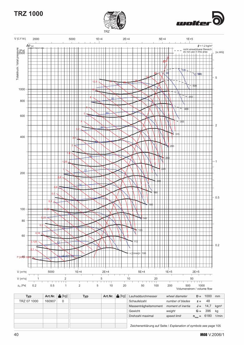
40 M08 V.2006/1
TRZ
Laufraddurchmesser wheel diameter D = mm
Schaufelzahl number of blades z =
Massenträgheitsmoment moment of inertia J = kgm²
Gewicht weight G = kg
Drehzahl maximal speed limit nmax = 1/min
Typ Art.Nr. [kg]
Zeichenerklärung auf Seite / Explanation of symbols see page 105
Typ Art.Nr. [kg]
TRZ 1000
1 10 100 10002 5 20 50 200 5000.50.2pd2 [Pa]
1E+4 1E+52E+4 5E+450002000·V [C.F.M.]
1 102 5 20 50·V [m³/s]
1E+4 1E+52E+4 5E+4 2E+55000·V [m³/h]
1
2
5
0.5
0.2
[in.WG]
100
1000
200
400
600
800
2000
80
60
40
[Pa]
n [1/min]= 100
112
125
140
160
180
200
225
250
280
315
355
400
450
500
560
Lw [dB(A)]= 59
62
65
68
71
74
77
80
83
86
89
92
95
98101
104
P [kW]= 0,08
0,1
0,125
0,16
0,2
0,25
0,32
0,4
0,5
0,6
0,8
1
1,25
1,6
2
2,5
3,2
4
5
6
8
10
12,5 16 20 2532
40
η max
Volumenstrom / volume flow
Totaldruck
/totalpressure 160907 TRZ 07 1000
totnicht einsetzbarer Bereichdo not use in this area
p = 1,2 kg/m³
100048
14,7396
6180
TRZ 07 1000 160907 0

41M08 V.2006/1
Laufraddurchmesser wheel diameter D = mm
Schaufelzahl number of blades z =
Massenträgheitsmoment moment of inertia J = kgm²
Gewicht weight G = kg
Drehzahl maximal speed limit nmax = 1/min
Typ Art.Nr. [kg]
Zeichenerklärung auf Seite / Explanation of symbols see page 105
Typ Art.Nr. [kg]
HRZ
HRZ 1000
1 10 100 10002 5 20 50 200 5000.50.2pd2 [Pa]
1E+4 1E+52E+4 5E+450002000·V [C.F.M.]
1 102 5 20 50·V [m³/s]
1E+4 1E+52E+4 5E+4 2E+55000·V [m³/h]
1
10
2
5
20
0.5
0.2
[in.WG]
100
1000
200
400
600
800
2000
4000
80
60
40
[Pa]
n [1/min]= 250
280
315
355
400
450
500
560
630
710
800
900
1000
1120
1250
1400
Lw [dB(A)]= 69
72
75
78
81
84
87
90
93
96
99
102
105
108
111
114
P [kW]= 0,16
0,2
0,25
0,32
0,4
0,5
0,6
0,8
1
1,25
1,6
2
2,5
3,2
4
5
6
8
10
12,5
16
20
25 32 40 η max
Volumenstrom / volume flow
Totaldruck
/totalpressure 240907 HRZ 07 1000
totnicht einsetzbarer Bereichdo not use in this area
p = 1,2 kg/m³
HRZ 07 1000 240907 3711000
1010,29371
1300

42 M08 V.2006/1
HRZTRZ HRZP
Maß- und Konstruktionsänderungen, dem technischen Fortschritt dienend, bleiben uns vorbehalten.We reserve the right to alter measurements without notice in case of technical improvements .
freies Wellenende
nutzbares Wellenende
n
f
h6d
h
p
C1
A3 A3
H1
H2
L5L6
H6
H5
Baugröße A A3 B B3 C C1 C2 C3 d H1 H2 H5 H6 h L5 L6 n p ØZ size [mm] [mm] [mm] [mm] [mm] [mm] [mm] [mm] [mm] [mm] [mm] [mm] [mm] [mm] [mm] [mm] [mm] [mm] [mm] 160 200 202 100 102 229 345 20 128 183 71 125 22,5 302 150 45 6 7 180 224 226 112 114 253 390 20 143 204 81 142 22,5 333 163 55 6 7 200 250 252 125 127 279 425 207,5 232,5 20 157 226 89 157 22,5 363 175 60 6 7 225 280 282 140 142 309 455 225 250 20 176 253 101 177 22,5 401 191 60 6 7 250 315 317 158 160 344 490 245 270 20 194 279 111 196 22,5 438 207 60 6 7 280 355 357 178 180 389 525 275 300 25 216 312 123 220 28 483 225 57 8 10 315 400 402 200 202 434 565 295 320 25 241 350 138 246 28 536 247 55 8 10 355 450 452 225 227 494 655 335 360 30 271 393 156 279 33 597 272 69 8 10 400 500 502 250 252 544 710 363 388 30 304 441 180 315 33 666 302 74 8 10 450 560 562 280 282 604 780 405 430 35 341 495 204 354 38 742 333 76 10 12 500 630 632 315 317 674 860 440,5 465,5 35 377 549 222 393 38 815 363 81 10 12 560 710 712 355 357 764 975 509,5 534,5 40 421 613 247 440 43 911 405 95 12 15 630 800 802 400 402 854 1065 554,0 579 40 473 689 278 493 43 1017 449 95 12 15 710 900 902 450 452 964 1210 619 644 50 532 775 314 552 53,3 1138 499 117 14 17
TRZ 00HRZ 00HRZP 00
RD = rechtsdrehend / clockwise LG = linksdrehend / anti-clockwise
Der Drehsinn wird durch Blick von der Antriebsseite bestimmt. / The direction of rotation is defined by vue on the side of drive .
RD 0 RD 90 RD 180 RD 270 LG 0 LG 90 LG 180 LG 270
AbmessungenDimensionsTRZ, HRZ, HRZP

43M08 V.2006/1
HRZTRZ HRZP
AbmessungenDimensionsTRZ, HRZ, HRZP
Maß- und Konstruktionsänderungen, dem technischen Fortschritt dienend, bleiben uns vorbehalten.We reserve the right to alter measurements without notice in case of technical improvements
freies Wellenende
nutzbares Wellenende
n
f
h6d
h
p
efx
125
Ø10X15
A2
A1
ØZ
CC1
AA1
A2 A
fx125e
L1
L3
H
H2
L7
H1
ØZLH
5
H8
H6
H9
Baugröße A A1 A2 A3 B B1 B2 C C1 C2 C3 d e e1 f fx125 f1x125 size [mm] [mm] [mm] [mm] [mm] [mm] [mm] [mm] [mm] [mm] [mm] [mm] [mm] [mm] [mm] 160 200 226 256 202 229 345 20 113 40 - - 180 224 250 280 226 253 390 20 125 40 - - 200 250 276 306 252 125 151 181 279 425 154 232,5 20 138 75,5 40 - - 225 280 306 336 282 140 166 196 309 455 169 250 20 153 133 40 - - 250 315 341 371 317 160 186 216 344 490 189 270 20 108 93 40 2 - 280 355 381 411 357 180 206 236 389 525 214 300 25 128 103 50 2 - 315 400 426 456 402 200 226 256 434 565 234 320 25 150,5 113 50 2 - 355 450 476 506 452 224 250 280 494 655 268 360 30 50,5 125 60 3 - 400 500 526 556 502 250 276 306 544 710 294 388 30 75,5 138 60 3 - 450 560 586 616 562 280 306 336 604 780 324 430 35 105,5 153 65 3 - 500 630 656 686 632 315 341 371 674 860 359 465,5 35 140,5 108 65 3 2 560 710 736 766 712 355 381 411 764 975 409 534,5 40 55,6 128 80 5 2 630 800 826 856 802 400 426 456 854 1065 454 579 40 100,5 150,5 80 5 2 710 900 926 956 902 964 1210 514 50 150,5 100 5
TRZ 03HRZ 03HRZP 03
Baugröße H H1 H2 H5 H6 H8 H9 h L L1 L3 L7 n p ØZ size [mm] [mm] [mm] [mm] [mm] [mm] [mm] [mm] [mm] [mm] [mm] [mm] [mm] [mm] [mm] [mm] 160 359 128 183 71 125 158 212 22,5 180 154 306 158 45 6 7 180 394 143 204 81 142 172 232 22,5 180 167 337 172 55 6 7 200 433 157 226 89 157 189 253 22,5 214 179 367 192 60 6 7 225 476 176 253 101 177 205 282 22,5 214 195 405 212 60 6 7 250 515 194 279 111 196 218 307 22,5 214 211 442 235 60 6 7 280 573 216 312 123 220 243 338 28 280 229 487 262 57 8 10 315 635 241 350 138 246 268 377 28 280 251 540 290 55 8 10 355 692 271 393 156 279 281 418 33 355 276 601 327 69 8 10 400 768 304 441 180 315 309 469 33 355 306 670 366 74 8 10 450 879 341 495 204 354 346 528 38 450 337 746 415 76 10 12 500 951 377 549 222 393 385 578 38 450 367 819 458 81 10 12 560 1055 421 613 247 440 424 642 43 500 409 915 510 95 12 15 630 1182 473 689 278 493 476 715 43 560 453 1021 579 95 12 15 710 1334 532 775 314 552 541 807 53,3 630 503 1142 646 117 14 17

44 M08 V.2006/1
HRZTRZ HRZP
AbmessungenDimensionsTRZ, HRZ, HRZP
Maß- und Konstruktionsänderungen, dem technischen Fortschritt dienend, bleiben uns vorbehalten.We reserve the right to alter measurements without notice in case of technical improvements .
freies Wellenende
nutzbares Wellenende
n
f
h6d
h
p
efx
125
Ø10X15
A2
A1
ØZ
C1
AA1
A2 A
fx125e
CC6
L1L3
H4
H2
H1
H6
H5
H
L4 L2
L5 L
H7
TRZ 05HRZ 05HRZP 05
Baugröße A A1 A2 A3 B B1 B2 C C1 C2 C3 C4 C5 C6 d e e1 size [mm] [mm] [mm] [mm] [mm] [mm] [mm] [mm] [mm] [mm] [mm] [mm] [mm] [mm] [mm] [mm] [mm] 200 250 276 306 252 125 151 181 279 425 154 232,5 179 425 20 138 75,5 225 280 306 336 282 140 166 196 309 455 169 250 194 334 20 153 133 250 315 341 371 317 160 186 216 344 490 189 270 214 369 20 108 93 280 355 381 411 357 180 206 236 389 525 214 300 244 419 25 128 103 315 400 426 456 402 200 226 256 434 565 234 320 264 464 25 150,5 113 355 450 476 506 452 224 250 280 494 655 268 360 308 534 30 50,5 125 400 500 526 556 502 250 276 306 544 710 294 388 334 584 30 75,5 138 450 560 586 616 562 280 306 336 604 780 324 430 364 640 35 105,5 153 500 630 656 686 632 315 341 371 674 860 359 465,5 399 714 35 140,5 108 560 710 736 766 712 355 381 411 764 975 409 534,5 459 814 40 55,6 128 630 800 826 856 802 400 426 456 854 1065 454 579 504 904 40 100,5 150,5 710 900 926 956 902 450 476 506 964 1210 514 664,0 554 1004 50 150,5 50,5
Baugröße f fx125 f1x125 H H1 H2 H3 H4 H5 H6 H7 h L L1 L2 L3 L4 L5 n p ØZ size [mm] [mm] [mm] [mm] [mm] [mm] [mm] [mm] [mm] [mm] [mm] [mm] [mm] [mm] [mm] [mm] [mm] [mm] [mm] 200 40 - - 400 157 226 224 89 157 80 23 224 179 188 367 132 48 60 6 7 225 40 - - 446 176 253 224 101 177 103 23 224 195 210 405 146 66 60 6 7 250 40 2 - 491 194 279 224 111 196 125 23 224 211 231 442 161 84 60 6 7 280 50 2 - 545 216 312 280 123 220 124 28 280 229 258 487 185 82 57 8 10 315 50 2 - 608 241 350 280 138 246 156 28 280 251 289 540 204 107 55 8 10 355 60 3 - 681 271 393 355 156 279 155 33 355 276 325 601 227 99 69 8 10 400 60 3 - 762 304 441 355 180 315 195 33 355 306 366 670 249 130 74 8 10 450 65 3 - 854 341 495 450 204 354 193 38 450 337 409 746 273 116 76 10 12 500 65 3 2 943 377 549 450 222 393 238 38 450 367 452 819 300 151 81 10 12 560 80 5 2 1052 421 613 500 247 440 267 43 500 409 506 915 337 172 95 12 15 630 80 5 2 1179 473 689 560 278 493 301 43 560 453 568 1021 370 189 95 12 15 710 100 5 3 1324 532 775 630 314 552 339 53 630 503 639 1142 413 211 117 14 17
RD = rechtsdrehend/ clockwise LG = linksdrehend/ anti-clockwise / rotation anti-horaire
Der Drehsinn wird durch Blick von der Antriebsseite bestimmt. / The direction of rotation is defined by vue on the side of drive .
RD 0 RD 90 RD 180 RD 270 LG 0 LG 90 LG 180 LG 270
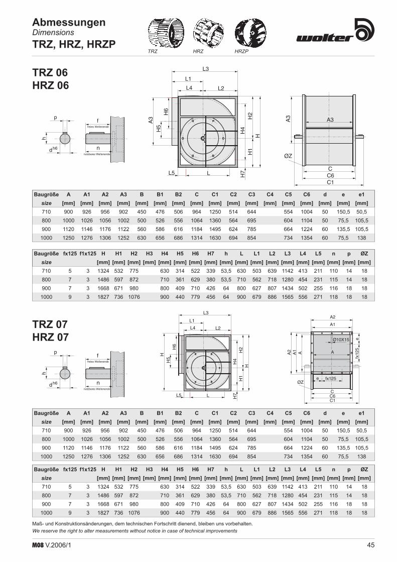
45M08 V.2006/1
HRZTRZ HRZP
AbmessungenDimensionsTRZ, HRZ, HRZP
Maß- und Konstruktionsänderungen, dem technischen Fortschritt dienend, bleiben uns vorbehalten.We reserve the right to alter measurements without notice in case of technical improvements
freies Wellenende
nutzbares Wellenende
n
f
h6d
h
p A3
ØZ
C6C
C1
A3
L5
H4
H2
H1
H
H6
H5
L
L4 L2
H7
A3
L1
L3TRZ 06HRZ 06
Baugröße A A1 A2 A3 B B1 B2 C C1 C2 C3 C4 C5 C6 d e e1 size [mm] [mm] [mm] [mm] [mm] [mm] [mm] [mm] [mm] [mm] [mm] [mm] [mm] [mm] [mm] [mm] [mm] 710 900 926 956 902 450 476 506 964 1250 514 644 554 1004 50 150,5 50,5 800 1000 1026 1056 1002 500 526 556 1064 1360 564 695 604 1104 50 75,5 105,5 900 1120 1146 1176 1122 560 586 616 1184 1495 624 785 664 1224 60 135,5 105,5 1000 1250 1276 1306 1252 630 656 686 1314 1630 694 854 734 1354 60 75,5 138
Baugröße fx125 f1x125 H H1 H2 H3 H4 H5 H6 H7 h L L1 L2 L3 L4 L5 n p ØZ size [mm] [mm] [mm] [mm] [mm] [mm] [mm] [mm] [mm] [mm] [mm] [mm] [mm] [mm] [mm] [mm] [mm] [mm] 710 5 3 1324 532 775 630 314 522 339 53,5 630 503 639 1142 413 211 110 14 18 800 7 3 1486 597 872 710 361 629 380 53,5 710 562 718 1280 454 231 115 14 18 900 7 3 1668 671 980 800 409 710 426 64 800 627 807 1434 502 255 116 18 18 1000 9 3 1827 736 1076 900 440 779 456 64 900 679 886 1565 556 271 118 18 18
freies Wellenende
nutzbares Wellenende
n
f
h6d
h
pe
fx12
5
Ø10X15
A2
A1
ØZ
C1
AA1
A2 A
fx125e
CC6L5
H4
H2
H1
H
H6
H5
L
L4 L2
H7
H
L1
L3
TRZ 07HRZ 07
Baugröße A A1 A2 A3 B B1 B2 C C1 C2 C3 C4 C5 C6 d e e1 size [mm] [mm] [mm] [mm] [mm] [mm] [mm] [mm] [mm] [mm] [mm] [mm] [mm] [mm] [mm] [mm] [mm] 710 900 926 956 902 450 476 506 964 1250 514 644 554 1004 50 150,5 50,5 800 1000 1026 1056 1002 500 526 556 1064 1360 564 695 604 1104 50 75,5 105,5 900 1120 1146 1176 1122 560 586 616 1184 1495 624 785 664 1224 60 135,5 105,5 1000 1250 1276 1306 1252 630 656 686 1314 1630 694 854 734 1354 60 75,5 138
Baugröße fx125 f1x125 H H1 H2 H3 H4 H5 H6 H7 h L L1 L2 L3 L4 L5 n p ØZ size [mm] [mm] [mm] [mm] [mm] [mm] [mm] [mm] [mm] [mm] [mm] [mm] [mm] [mm] [mm] [mm] [mm] [mm] 710 5 3 1324 532 775 630 314 522 339 53,5 630 503 639 1142 413 211 110 14 18 800 7 3 1486 597 872 710 361 629 380 53,5 710 562 718 1280 454 231 115 14 18 900 7 3 1668 671 980 800 409 710 426 64 800 627 807 1434 502 255 116 18 18 1000 9 3 1827 736 1076 900 440 779 456 64 900 679 886 1565 556 271 118 18 18

46 M08 V.2006/1
HRZTRZ HRZP
AbmessungenDimensionsTRZ, HRZ, HRZP
Maß- und Konstruktionsänderungen, dem technischen Fortschritt dienend, bleiben uns vorbehalten.We reserve the right to alter measurements without notice in case of technical improvements .
Baugröße max.Motor L e1 e2 H BZ CZ x1 y d H1 H2 H3 G W
size max. motor [mm] [mm] [mm] [mm] [mm] [mm] [mm] [mm] [mm] [mm] [mm] [mm] [mm] [mm] [kg] 160 112M 560 150 200 98 258 230 578 14 10,5 123 158 229 154 260 4,0 180 112M 560 150 200 98 282 254 578 14 10,5 123 172 253 167 270 4,2 200 112M 640 170 230 108 308 280 658 14 10,5 133 189 278 179 310 4,5 225 112M 640 170 230 108 338 310 658 14 10,5 133 205 306 195 320 5,0 250 132S 640 170 230 108 373 345 658 14 10,5 133 218 329 211 340 5,8 280 132S 750 207 243 105 417 387 768 15 10,5 130 243 366 229 400 7,0 315 132S 750 207 243 105 462 432 768 15 10,5 130 268 406 241 415 7,3 355 132S 880 250 260 133 532 492 918 20 12 158 281 437 276 480 14,4 400 132S 880 250 260 133 582 542 918 20 12 158 309 489 306 505 14,8 450 132S 1065 300 300 188 642 602 1103 20 12 213 346 550 337 590 16,5 500 132S 1065 300 300 188 712 672 1103 20 12 213 385 607 367 600 17,0
Grundrahmen mit MotorwippeBase frame with motor bracketCadre de base avec fixation mobile pour moteur
CZ
BZ
W G
H2
H3
HH1
e1
L
x1
d
RD = rechtsdrehend/ clockwise LG = linksdrehend/ anti-clockwise
Der Drehsinn wird durch Blick von der Antriebsseite bestimmt. / The direction of rotation is defined by vue on the side of drive .
RD 0 RD 90 RD 180 RD 270 LG 0 LG 90 LG 180 LG 270

47M08 V.2006/1
HRZTRZ HRZP
AbmessungenDimensionsTRZ, HRZ, HRZP
Maß- und Konstruktionsänderungen, dem technischen Fortschritt dienend, bleiben uns vorbehalten.We reserve the right to alter measurements without notice in case of technical improvements
hv3x
l1
me1e2
e3e4
d3
Baugröße max.Motor d3 e1 e2 e3 e4 l1 m h v3 x size max. motor [mm] [mm] [mm] [mm] [mm] [mm] [mm] [mm] [mm] [mm] 710 250M 18 25 650 1250 1875 1900 100 175 1024 961 800 250M 18 25 650 1350 1975 2000 100 175 1124 1071 900 280 18 25 910 1590 2475 2500 100 175 1244 1194 1000 280 18 25 910 1890 2775 2800 100 175 1374 1331
Positionsmaße (e1-e4) zur Befestigung von Schwin-gungsdämpfern.Motorgröße bei Bestellung angeben.
e1-e4 fixing position of vibration damper.Motor size is to be specified when ordering.
hv3x
d3
e
y1 y1
l1
m
f
Baugröße max.Motor d3 e f l1 m h v3 x y1
size max. motor [mm] [mm] [mm] [mm] [mm] [mm] [mm] [mm] [mm] [kg] 280 132M 12 1050 28 1120 28 96 442 382 140 7,0 315 132M 12 1050 28 1120 28 96 486 436 140 7,3 355 160M 12 1180 50 1250 40 120 554 494 177,5 14,4 400 160M 12 1180 50 1250 40 120 608 549 177,5 14,8 450 160L 12 1330 50 1400 40 120 670 611 225 16,5 500 160L 12 1330 50 1400 40 120 740 681 225 17,0 560 180M 15 1530 50 1600 40 (60) 120 (140) 838 768 250 30,5 630 180L 15 1530 50 1600 40 (60) 120 (140) 924 854 280 31,6
Grundrahmen mit Motorschlitten, leichte Ausführung.Base frame with motor slide, light duty .Cadre de base avec glissière de moteur, modè-le léger .
Grundrahmen mit Motorschlitten, schwere Ausführung.Base frame with motor slide, heavy duty .

48 M08 V.2006/1
HRZTRZ HRZP
AbmessungenDimensionsTRZ, HRZ, HRZP
Maß- und Konstruktionsänderungen, dem technischen Fortschritt dienend, bleiben uns vorbehalten.We reserve the right to alter measurements without notice in case of technical improvements .
x
v3
m h
l 2
Baugröße max.Motor l2 h m v3 x
size max. motor [mm] [mm] [mm] [mm] [mm] [kg] 200 90S 313 89 28 324 282 1,8 225 90L 348 89 28 354 314 2,0 250 100L 384 89 28 389 348 2,2 280 100L 433 89 28 439 392 4,1 315 100L 481 89 28 484 436 4,5 355 112M 541 89 28 554 494 9,0 400 112M 606 89 28 604 548 10,0 450 132S 674 160 40 660 610 11,0 500 132M 743 160 40 734 680 12,2 560 160M 837 160 40 834 768 21,5 630 160M 935 160 40 924 854 23,8 710 160L 1049 184 60 1024 961 33,5 800 180M 1174 184 60 1124 1071 37,2 900 180L 1313 184 60 1244 1194 41,2 1000 200L 1444 184 60 1394 1331 45,5
Motorbefestigung RechteckrahmenScroll mounted base frame
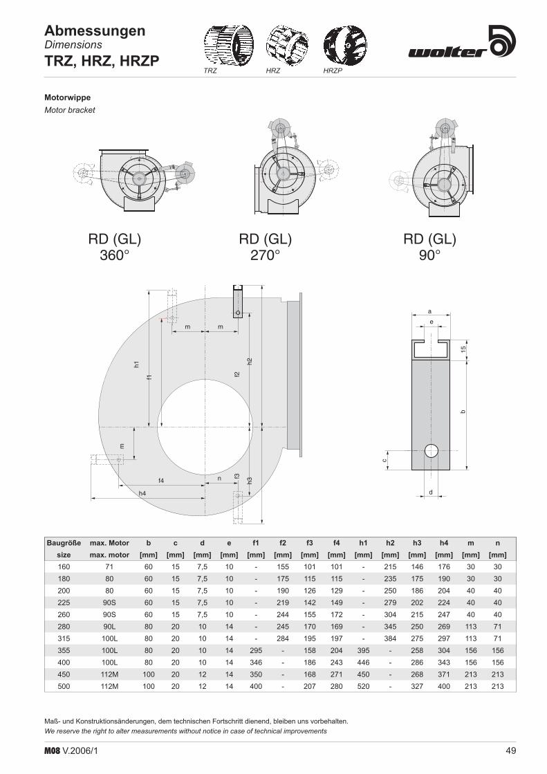
49M08 V.2006/1
HRZTRZ HRZP
AbmessungenDimensionsTRZ, HRZ, HRZP
Maß- und Konstruktionsänderungen, dem technischen Fortschritt dienend, bleiben uns vorbehalten.We reserve the right to alter measurements without notice in case of technical improvements
m m
m
n
f1 f2
h2h1
f4
h4
h3
f3RD (GL)
360°RD (GL)
270°RD (GL)
90°
e
a
15b
c
d
Baugröße max. Motor b c d e f1 f2 f3 f4 h1 h2 h3 h4 m n size max. motor [mm] [mm] [mm] [mm] [mm] [mm] [mm] [mm] [mm] [mm] [mm] [mm] [mm] [mm] 160 71 60 15 7,5 10 - 155 101 101 - 215 146 176 30 30 180 80 60 15 7,5 10 - 175 115 115 - 235 175 190 30 30 200 80 60 15 7,5 10 - 190 126 129 - 250 186 204 40 40 225 90S 60 15 7,5 10 - 219 142 149 - 279 202 224 40 40 260 90S 60 15 7,5 10 - 244 155 172 - 304 215 247 40 40 280 90L 80 20 10 14 - 245 170 169 - 345 250 269 113 71 315 100L 80 20 10 14 - 284 195 197 - 384 275 297 113 71 355 100L 80 20 10 14 295 - 158 204 395 - 258 304 156 156 400 100L 80 20 10 14 346 - 186 243 446 - 286 343 156 156 450 112M 100 20 12 14 350 - 168 271 450 - 268 371 213 213 500 112M 100 20 12 14 400 - 207 280 520 - 327 400 213 213
MotorwippeMotor bracket
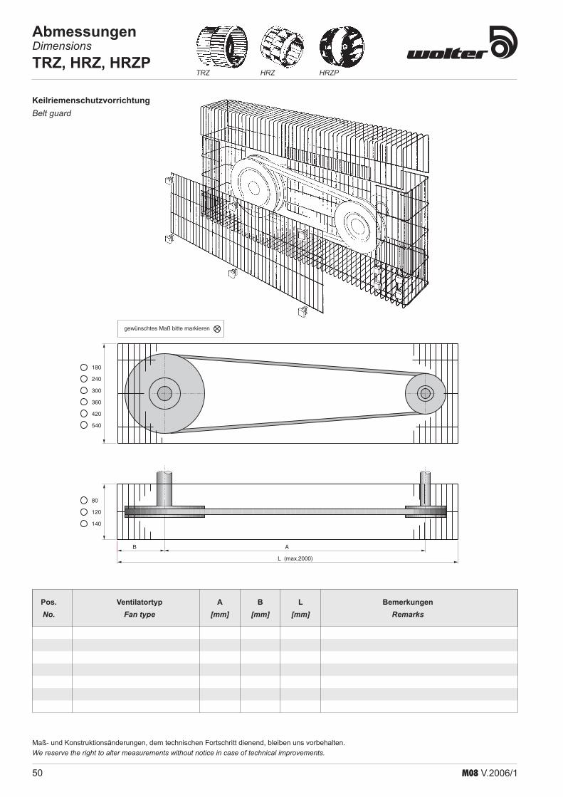
50 M08 V.2006/1
HRZTRZ HRZP
AbmessungenDimensionsTRZ, HRZ, HRZP
Maß- und Konstruktionsänderungen, dem technischen Fortschritt dienend, bleiben uns vorbehalten.We reserve the right to alter measurements without notice in case of technical improvements .
B A
L (max.2000)
180
240
300
360
420
540
80
120
140
gewünschtes Maß bitte markieren
KeilriemenschutzvorrichtungBelt guard
Pos. Ventilatortyp A B L Bemerkungen No. Fan type [mm] [mm] [mm] Remarks

51M08 V.2006/1
HRZTRZ HRZP
AbmessungenDimensionsTRZ, HRZ, HRZP
Maß- und Konstruktionsänderungen, dem technischen Fortschritt dienend, bleiben uns vorbehalten.We reserve the right to alter measurements without notice in case of technical improvements
VentilatorseitenbodenFan side plate
Baugröße A B C F1 F2 F3 G1 G2 G3 G4 X1 X2 X3 Y1 Y2 Y3 *
size [mm] [mm] [mm] [mm] [mm] [mm] [mm] [mm] [mm] [mm] [mm] [mm] [mm] [mm] [mm] [mm] [mm]
160 30 30 30 - - - 155 101 101 101 121 92 67 92 67 92 Ø 6,3
180 30 30 30 - - - 175 115 115 115 141 92 81 92 81 92 Ø 6,3
200 40 40 40 202 163 134 190 129 126 126 155 110 91 110 94 110 Ø 6,3
225 40 40 40 229 185 152 219 149 142 142 184 110 107 110 114 110 Ø 6,3
260 40 40 40 256 208 171 244 172 155 155 209 110 120 110 137 110 Ø 6,3
280 113 113 71 287 233 191 245 169 150 170 - - - - - - Ø 8
315 113 113 71 323 263 215 284 197 175 195 - - - - - - Ø 8
355 156 156 156 364 295 241 295 204 158 158 197,5 - - 197,5 - - Ø 8
400 156 156 156 411 336 275 346 243 186 186 220 - - 220 - - Ø 8
450 213 213 213 466 379 311 350 271 168 168 245 - - 245 - - M 8
500 213 213 213 519 423 349 400 280 207 207 270 - - 270 - - M 8
560 235 235 235 581 472 389 494 362 276 276 305 - - 305 - - M 12
630 235 235 235 656 535 441 567 431 328 328 340 - - 340 - - M 12
710 265 265 265 737 601 496 637 476 371 371 377,5 - - 377,5 - - M 12
Ab Baugröße 200 sind Maße für die Ausführungen TRE/HRE indentisch.For sizes 200 up to 710 dimensions for models TRE/HRE are identical .
*
**
*
**
*
**
*
**
C BY3
G2F2
A BY1 Y2
F1
G1
X1
F3 G4
AB
X3
X2
G3
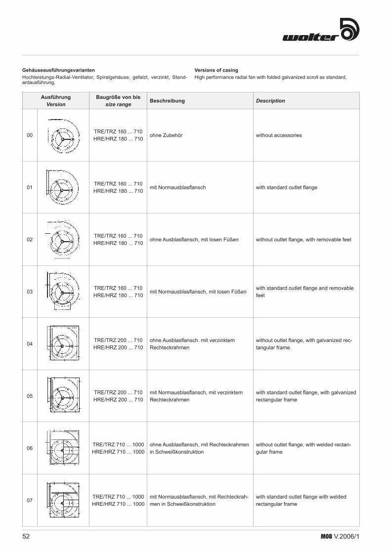
52 M08 V.2006/1
Versions of casingHigh performance radial fan with folded galvanized scroll as standard,
AusführungVersion
Baugröße von bissize range Beschreibung Description
00TRE/TRZ 160 ... 710HRE/HRZ 180 ... 710
ohne Zubehör without accessories
01TRE/TRZ 160 ... 710HRE/HRZ 180 ... 710
mit Normausblasflansch with standard outlet flange
02TRE/TRZ 160 ... 710HRE/HRZ 180 ... 710
ohne Ausblasflansch, mit losen Füßen without outlet flange, with removable feet
03TRE/TRZ 160 ... 710HRE/HRZ 180 ... 710
mit Normausblasflansch, mit losen Füßen with standard outlet flange and removable feet
04TRE/TRZ 200 ... 710HRE/HRZ 200 ... 710
ohne Ausblasflansch. mit verzinktem Rechteckrahmen
without outlet flange, with galvanized rec-tangular frame
05TRE/TRZ 200 ... 710HRE/HRZ 200 ... 710
mit Normausblasflansch, mit verzinktem Rechteckrahmen
with standard outlet flange, with galvanized rectangular frame
06TRE/TRZ 710 ... 1000HRE/HRZ 710 ... 1000
ohne Ausblasflansch, mit Rechteckrahmen in Schweißkonstruktion
without outlet flange, with welded rectan-gular frame
07TRE/TRZ 710 ... 1000HRE/HRZ 710 ... 1000
mit Normausblasflansch, mit Rechteckrah-men in Schweißkonstruktion
with standard outlet flange with welded rectangular frame
GehäuseausführungsvariantenHochleistungs-Radial-Ventilator, Spiralgehäuse, gefalzt, verzinkt, Stand-ardausführung,

53M08 V.2006/1
Radialventilatoren- keilriemengetrieben- einseitig saugend- mit vor- und rückwerts-
gekrümmten Schaufeln
Centrifugal fans- belt driven- single inlet- with backward and forward curved
impellers
KennlinienPerformance curvesTRE, HRE
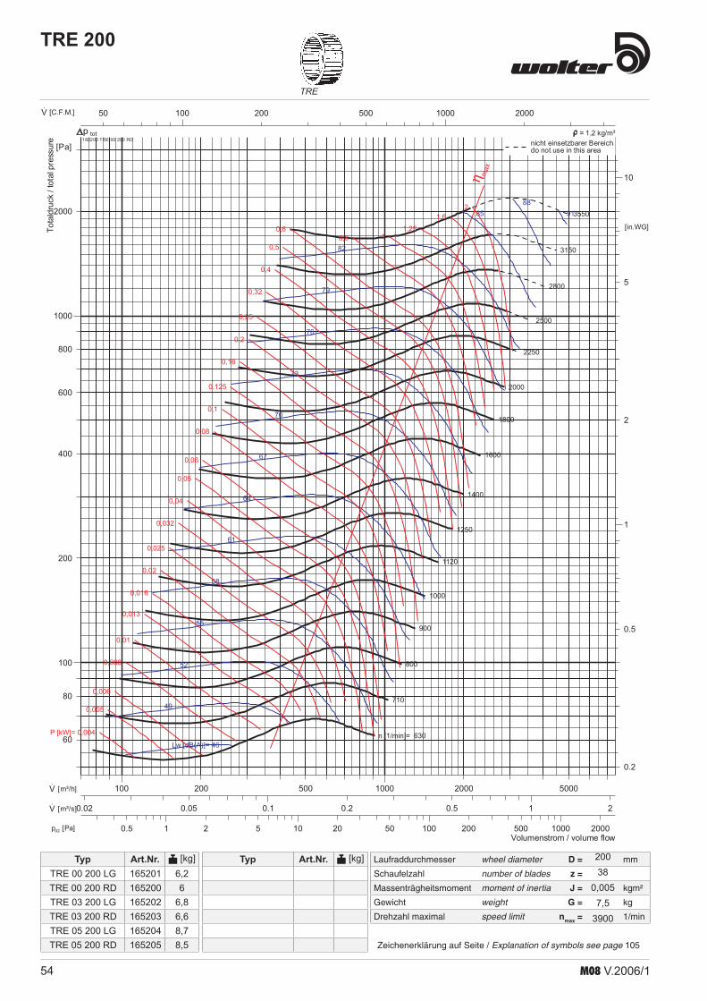
54 M08 V.2006/1
Laufraddurchmesser wheel diameter D = mm
Schaufelzahl number of blades z =
Massenträgheitsmoment moment of inertia J = kgm²
Gewicht weight G = kg
Drehzahl maximal speed limit nmax = 1/min
TRE
Typ Art.Nr. [kg]
Zeichenerklärung auf Seite / Explanation of symbols see page 105
Typ Art.Nr. [kg]
TRE 200
1 10 100 10002 5 20 50 200 500 20000.5pd2 [Pa]
100 1000200 500 200050·V [C.F.M.]
0.1 10.2 0.5 20.050.02·V [m³/s]
100 1000200 500 2000 5000·V [m³/h]
1
10
2
5
0.5
0.2
[in.WG]
100
1000
200
400
600
800
2000
80
60
[Pa]
n [1/min]= 630
710
800
900
1000
1120
1250
1400
1600
1800
2000
2250
2500
2800
3150
3550
Lw [dB(A)]= 46
49
52
55
58
61
64
67
70
73
76
79
82
8588
91
P [kW]= 0,004
0,005
0,006
0,008
0,01
0,013
0,016
0,02
0,025
0,032
0,04
0,05
0,06
0,08
0,1
0,125
0,16
0,2
0,25
0,32
0,4
0,5
0,60,8 1
1,251,6
2
η max
Volumenstrom / volume flow
Totaldruck
/totalpressure 165200 TRE 00 200 RD
totnicht einsetzbarer Bereichdo not use in this area
p = 1,2 kg/m³
TRE 00 200 LGTRE 00 200 RDTRE 03 200 LGTRE 03 200 RDTRE 05 200 LGTRE 05 200 RD
165201165200165202165203165204165205
6,26
6,86,68,78,5
20038
0,0057,5
3900

55M08 V.2006/1
HRE
Laufraddurchmesser wheel diameter D = mm
Schaufelzahl number of blades z =
Massenträgheitsmoment moment of inertia J = kgm²
Gewicht weight G = kg
Drehzahl maximal speed limit nmax = 1/min
Typ Art.Nr. [kg]
Zeichenerklärung auf Seite / Explanation of symbols see page 105
Typ Art.Nr. [kg]
HRE 200
1 10 1002 5 20 50 200 5000.50.2pd2 [Pa]
100 1000200 500 200050·V [C.F.M.]
0.1 10.2 0.50.050.02·V [m³/s]
100 1000200 500 2000·V [m³/h]
0.1
1
10
0.2
0.5
2
5
[in.WG]
100
1000
200
400
600
800
2000
80
60
40
[Pa]
n [1/min]= 1120
1250
1400
1600
1800
2000
2250
2500
2800
3150
3550
4000
4500
5000
5600
6300
Lw [dB(A)]= 47
50
53
56
59
62
65
68
71
74
77
80
83
86
89
92
P [kW]= 0,002
0,0025
0,0032
0,004
0,005
0,006
0,008
0,01
0,013
0,016
0,02
0,025
0,032
0,04
0,05
0,06
0,08
0,1
0,125
0,16
0,2
0,25
0,32 0,4 0,5 0,6 0,8 1 η max
Volumenstrom / volume flow
Totaldruck
/totalpressure 166200 HRE 00 200 RD
totnicht einsetzbarer Bereichdo not use in this area
p = 1,2 kg/m³
20010
0,0046,9
7000
HRE 00 200 RDHRE 00 200 LGHRE 03 200 LGHRE 03 200 RDHRE 05 200 LGHRE 05 200 RD
166200166201166202166203166204166205
6,26,26,86,88,78,7

56 M08 V.2006/1
Laufraddurchmesser wheel diameter D = mm
Schaufelzahl number of blades z =
Massenträgheitsmoment moment of inertia J = kgm²
Gewicht weight G = kg
Drehzahl maximal speed limit nmax = 1/min
TRE
Typ Art.Nr. [kg]
Zeichenerklärung auf Seite / Explanation of symbols see page 105
Typ Art.Nr. [kg]
TRE 225
1 10 100 10002 5 20 50 200 500 20000.5pd2 [Pa]
100 1000200 500 2000 5000·V [C.F.M.]
0.1 10.2 0.5 20.05·V [m³/s]
100 1000200 500 2000 5000·V [m³/h]
1
10
2
5
0.5
0.2
[in.WG]
100
1000
200
400
600
800
2000
80
60
[Pa]
n [1/min]= 560
630
710
800
900
1000
1120
1250
1400
1600
1800
2000
2250
2500
2800
3150
Lw [dB(A)]= 47
50
53
56
59
62
65
68
71
74
77
80
83
8689
92
P [kW]= 0,005
0,006
0,008
0,01
0,013
0,016
0,02
0,025
0,032
0,04
0,05
0,06
0,08
0,1
0,125
0,16
0,2
0,25
0,32
0,4
0,5
0,6
0,81 1,25
1,62
2,5
η max
Volumenstrom / volume flow
Totaldruck
/totalpressure 165250 TRE 00 225 RD
totnicht einsetzbarer Bereichdo not use in this area
p = 1,2 kg/m³
22542
0,00958,1
3400
TRE 00 225 LGTRE 00 225 RDTRE 03 225 LGTRE 03 225 RDTRE 05 225 LGTRE 05 225 RD
165251165250165252165253165254165255
7,27,68
8,410,210,6
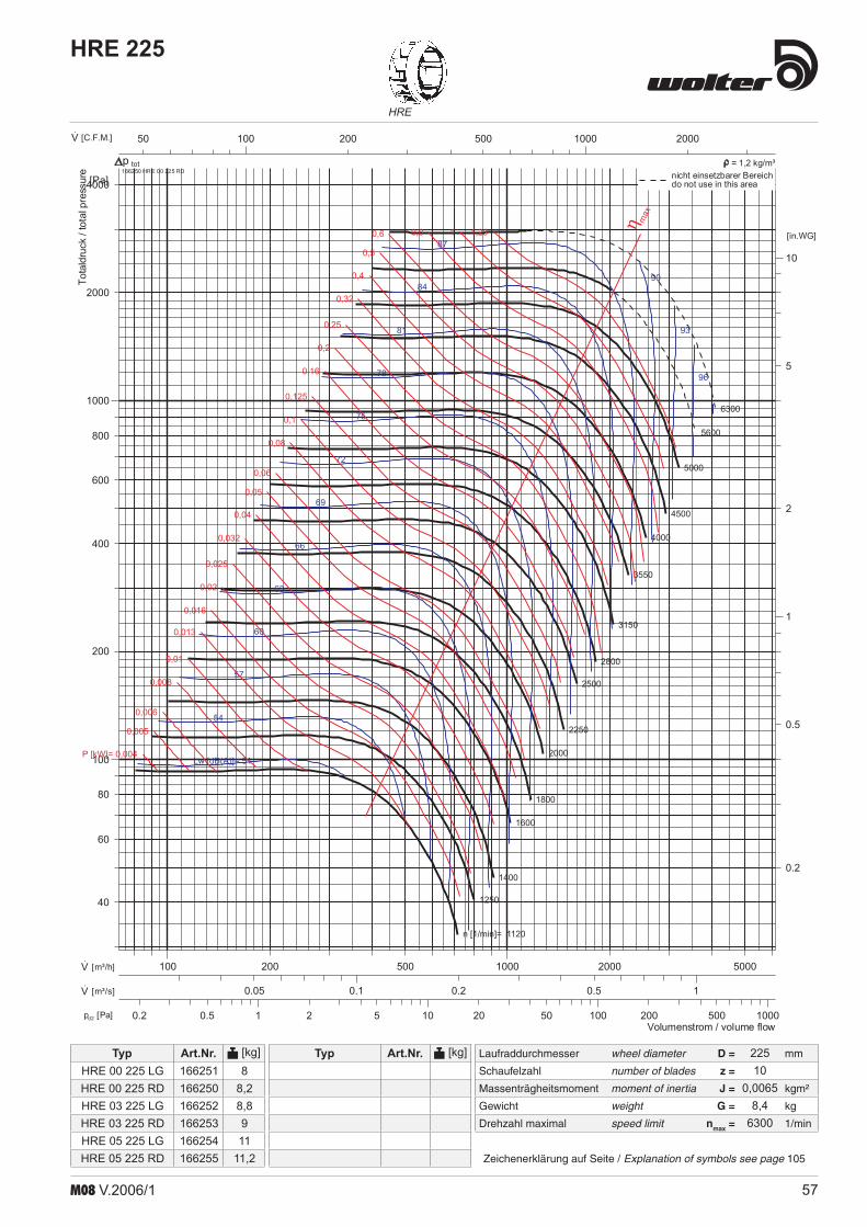
57M08 V.2006/1
HRE
Laufraddurchmesser wheel diameter D = mm
Schaufelzahl number of blades z =
Massenträgheitsmoment moment of inertia J = kgm²
Gewicht weight G = kg
Drehzahl maximal speed limit nmax = 1/min
Typ Art.Nr. [kg]
Zeichenerklärung auf Seite / Explanation of symbols see page 105
Typ Art.Nr. [kg]
HRE 225
1 10 100 10002 5 20 50 200 5000.50.2pd2 [Pa]
100 1000200 500 200050·V [C.F.M.]
0.1 10.2 0.50.05·V [m³/s]
100 1000200 500 2000 5000·V [m³/h]
1
10
2
5
0.5
0.2
[in.WG]
100
1000
200
400
600
800
2000
4000
80
60
40
[Pa]
n [1/min]= 1120
1250
1400
1600
1800
2000
2250
2500
2800
3150
3550
4000
4500
5000
5600
6300
Lw [dB(A)]= 51
54
57
60
63
66
69
72
75
78
81
84
87
90
93
96
P [kW]= 0,004
0,005
0,006
0,008
0,01
0,013
0,016
0,02
0,025
0,032
0,04
0,05
0,06
0,08
0,1
0,125
0,16
0,2
0,25
0,32
0,4
0,5
0,6 0,8 1 1,25 η max
Volumenstrom / volume flow
Totaldruck
/totalpressure 166250 HRE 00 225 RD
totnicht einsetzbarer Bereichdo not use in this area
p = 1,2 kg/m³
22510
0,00658,4
6300
HRE 00 225 LGHRE 00 225 RDHRE 03 225 LGHRE 03 225 RDHRE 05 225 LGHRE 05 225 RD
166251166250166252166253166254166255
88,28,8911
11,2

58 M08 V.2006/1
Laufraddurchmesser wheel diameter D = mm
Schaufelzahl number of blades z =
Massenträgheitsmoment moment of inertia J = kgm²
Gewicht weight G = kg
Drehzahl maximal speed limit nmax = 1/min
TRE
Typ Art.Nr. [kg]
Zeichenerklärung auf Seite / Explanation of symbols see page 105
Typ Art.Nr. [kg]
TRE 250
1 10 100 10002 5 20 50 200 500 20000.5pd2 [Pa]
100 1000200 500 2000 5000·V [C.F.M.]
0.1 10.2 0.5 20.05·V [m³/s]
1000 1E+42000 5000500200·V [m³/h]
1
10
2
5
0.5
0.2
[in.WG]
100
1000
200
400
600
800
2000
80
60
[Pa]
n [1/min]= 500
560
630
710
800
900
1000
1120
1250
1400
1600
1800
2000
2250
2500
2800
Lw [dB(A)]= 48
51
54
57
60
63
66
69
72
75
78
81
84
8790
93
P [kW]= 0,005
0,006
0,008
0,01
0,013
0,016
0,02
0,025
0,032
0,04
0,05
0,06
0,08
0,1
0,125
0,16
0,2
0,25
0,32
0,4
0,5
0,6
0,8 1 1,25 1,62
2,5
η max
Volumenstrom / volume flow
Totaldruck/totalpressure 165300 TRE 00 250 RD
totnicht einsetzbarer Bereichdo not use in this area
p = 1,2 kg/m³
25038
0,01513
3000
TRE 00 280 RDTRE 00 280 LGTRE 03 280 LGTRE 03 280 RDTRE 05 280 LGTRE 05 280 RD
165350165351165352165353165354165355
1212,213,913,717,317,1

59M08 V.2006/1
HRE
Laufraddurchmesser wheel diameter D = mm
Schaufelzahl number of blades z =
Massenträgheitsmoment moment of inertia J = kgm²
Gewicht weight G = kg
Drehzahl maximal speed limit nmax = 1/min
Typ Art.Nr. [kg]
Zeichenerklärung auf Seite / Explanation of symbols see page 105
Typ Art.Nr. [kg]
HRE 250
1 10 100 10002 5 20 50 200 5000.50.2pd2 [Pa]
100 1000200 500 2000·V [C.F.M.]
0.1 10.2 0.5 20.05·V [m³/s]
100 1000200 500 2000 5000·V [m³/h]
1
10
2
5
0.5
0.2
[in.WG]
100
1000
200
400
600
800
2000
4000
80
60
40
[Pa]
n [1/min]= 1000
1120
1250
1400
1600
1800
2000
2250
2500
2800
3150
3550
4000
4500
5000
5600
Lw [dB(A)]= 52
55
58
61
64
67
70
73
76
79
82
85
88
91
94
97
P [kW]= 0,005
0,006
0,008
0,01
0,013
0,016
0,02
0,025
0,032
0,04
0,05
0,06
0,08
0,1
0,125
0,16
0,2
0,25
0,32
0,4
0,5
0,6
0,8 1 1,25 1,6 2 η max
Volumenstrom / volume flow
Totaldruck/totalpressure 166300 HRE 00 250 RD
totnicht einsetzbarer Bereichdo not use in this area
p = 1,2 kg/m³
25010
0,01059,3
5600
HRE 00 250 LGHRE 00 250 RDHRE 03 250 LGHRE 03 250 RDHRE 05 250 LGHRE 05 250 RD
166301166300166302166303166304166305
8,68,69,59,511,711,7

60 M08 V.2006/1
Laufraddurchmesser wheel diameter D = mm
Schaufelzahl number of blades z =
Massenträgheitsmoment moment of inertia J = kgm²
Gewicht weight G = kg
Drehzahl maximal speed limit nmax = 1/min
TRE
Typ Art.Nr. [kg]
Zeichenerklärung auf Seite / Explanation of symbols see page 105
Typ Art.Nr. [kg]
TRE 280
1 10 100 10002 5 20 50 200 500 20000.5pd2 [Pa]
100 1000200 500 2000 5000·V [C.F.M.]
0.1 10.2 0.5 20.05·V [m³/s]
1000 1E+42000 5000500200·V [m³/h]
1
10
2
5
0.5
0.2
[in.WG]
100
1000
200
400
600
800
2000
80
60
[Pa]
n [1/min]= 450
500
560
630
710
800
900
1000
1120
1250
1400
1600
1800
2000
2250
2500
Lw [dB(A)]= 49
52
55
58
61
64
67
70
73
76
79
82
85
8891
94
P [kW]= 0,008
0,01
0,013
0,016
0,02
0,025
0,032
0,04
0,05
0,06
0,08
0,1
0,125
0,16
0,2
0,25
0,32
0,4
0,5
0,6
0,8
1 1,25 1,6 22,5
3,24
η max
Volumenstrom / volume flow
Totaldruck/totalpressure 165350 TRE 00 280 RD
totnicht einsetzbarer Bereichdo not use in this area
p = 1,2 kg/m³
28042
0,027513
2800
TRE 00 280 RDTRE 00 280 LGTRE 03 280 LGTRE 03 280 RDTRE 05 280 LGTRE 05 280 RD
165350165351165352165353165354165355
1212,213,913,717,317,1

61M08 V.2006/1
HRE
Laufraddurchmesser wheel diameter D = mm
Schaufelzahl number of blades z =
Massenträgheitsmoment moment of inertia J = kgm²
Gewicht weight G = kg
Drehzahl maximal speed limit nmax = 1/min
Typ Art.Nr. [kg]
Zeichenerklärung auf Seite / Explanation of symbols see page 105
Typ Art.Nr. [kg]
HRE 280
1 10 100 10002 5 20 50 200 5000.50.2pd2 [Pa]
100 1000200 500 2000 5000·V [C.F.M.]
0.1 10.2 0.5 20.05·V [m³/s]
1000 2000 5000500200·V [m³/h]
1
10
2
5
0.5
0.2
[in.WG]
100
1000
200
400
600
800
2000
4000
80
60
40
[Pa]
n [1/min]= 900
1000
1120
1250
1400
1600
1800
2000
2250
2500
2800
3150
3550
4000
4500
5000
Lw [dB(A)]= 54
57
60
63
66
69
72
75
78
81
84
87
90
93
96
99
P [kW]= 0,006
0,008
0,01
0,013
0,016
0,02
0,025
0,032
0,04
0,05
0,06
0,08
0,1
0,125
0,16
0,2
0,25
0,32
0,4
0,5
0,6
0,8
1 1,25 1,6 2 2,5 η max
Volumenstrom / volume flow
Totaldruck/totalpressure 166350 HRE 00 280 RD
totnicht einsetzbarer Bereichdo not use in this area
p = 1,2 kg/m³
28010
0,018512,75000
HRE 00 280 LGHRE 00 280 RDHRE 03 280 LGHRE 03 280 RDHRE 05 280 LGHRE 05 280 RD
166351166350166352166353166354166355
11,811,613,513,216,916,7

62 M08 V.2006/1
Laufraddurchmesser wheel diameter D = mm
Schaufelzahl number of blades z =
Massenträgheitsmoment moment of inertia J = kgm²
Gewicht weight G = kg
Drehzahl maximal speed limit nmax = 1/min
TRE
Typ Art.Nr. [kg]
Zeichenerklärung auf Seite / Explanation of symbols see page 105
Typ Art.Nr. [kg]
TRE 315
1 10 100 10002 5 20 50 200 500 20000.5pd2 [Pa]
1000 1E+42000 5000500200·V [C.F.M.]
0.1 10.2 0.5 2 50.05·V [m³/s]
1000 1E+42000 5000500200·V [m³/h]
1
10
2
5
0.5
0.2
[in.WG]
100
1000
200
400
600
800
2000
80
60
[Pa]
n [1/min]= 400
450
500
560
630
710
800
900
1000
1120
1250
1400
1600
1800
2000
2250
Lw [dB(A)]= 50
53
56
59
62
65
68
71
74
77
80
83
86
89
9295
P [kW]= 0,008
0,01
0,013
0,016
0,02
0,025
0,032
0,04
0,05
0,06
0,08
0,1
0,125
0,16
0,2
0,25
0,32
0,4
0,5
0,6
0,8
1
1,251,6 2 2,5
3,24
η max
Volumenstrom / volume flow
Totaldruck/totalpressure 165400 TRE 00 315 RD
totnicht einsetzbarer Bereichdo not use in this area
p = 1,2 kg/m³
TRE 00 315 LGTRE 00 315 RDTRE 03 315 LGTRE 03 315 RDTRE 05 315 LGTRE 05 315 RD
165401165400165402165403165404165405
14,614,616,416,421,421,4
31538
0,0416,22400
TREB 315 LG 0°TREB 315 LG 270°TREB 315 LG 90°TREB 315 RD 0°
TREB 315 RD 90°TREB 315 RD 270°
168004168006168005168001168002168003

63M08 V.2006/1
HRE
Laufraddurchmesser wheel diameter D = mm
Schaufelzahl number of blades z =
Massenträgheitsmoment moment of inertia J = kgm²
Gewicht weight G = kg
Drehzahl maximal speed limit nmax = 1/min
Typ Art.Nr. [kg]
Zeichenerklärung auf Seite / Explanation of symbols see page 105
Typ Art.Nr. [kg]
HRE 315
1 10 1002 5 20 50 200 5000.50.2pd2 [Pa]
100 1000200 500 2000 5000·V [C.F.M.]
0.1 10.2 0.5 20.05·V [m³/s]
1000 1E+42000 5000500200·V [m³/h]
1
10
2
5
0.5
0.2
[in.WG]
100
1000
200
400
600
800
2000
4000
80
60
40
[Pa]
n [1/min]= 800
900
1000
1120
1250
1400
1600
1800
2000
2250
2500
2800
3150
3550
4000
4500
Lw [dB(A)]= 55
58
61
64
67
70
73
76
79
82
85
88
91
94
97
100
P [kW]= 0,008
0,01
0,013
0,016
0,02
0,025
0,032
0,04
0,05
0,06
0,08
0,1
0,125
0,16
0,2
0,25
0,32
0,4
0,5
0,6
0,8
1
1,25 1,6 2 2,5 η max
Volumenstrom / volume flow
Totaldruck/totalpressure 166400 HRE 00 315 RD
totnicht einsetzbarer Bereichdo not use in this area
p = 1,2 kg/m³
31510
0,02815,14500
HRE 00 315 LGHRE 00 315 RDHRE 03 315 LGHRE 03 315 RDHRE 05 315 LGHRE 05 315 RD
HREB 315 LG 0°HREB 315 LG 270°HREB 315 LG 90°HREB 315 RD 0°
HREB 315 RD 90°HREB 315 RD 270°
166401166400166402166403166404166405
168103168105168104168100168101168102
14,214,216162121
0

64 M08 V.2006/1
Laufraddurchmesser wheel diameter D = mm
Schaufelzahl number of blades z =
Massenträgheitsmoment moment of inertia J = kgm²
Gewicht weight G = kg
Drehzahl maximal speed limit nmax = 1/min
TRE
Typ Art.Nr. [kg]
Zeichenerklärung auf Seite / Explanation of symbols see page 105
Typ Art.Nr. [kg]
TRE 355
1 10 100 10002 5 20 50 200 500 20000.5pd2 [Pa]
1000 1E+42000 5000500200·V [C.F.M.]
0.1 10.2 0.5 2 5·V [m³/s]
1000 1E+42000 5000 2E+4500·V [m³/h]
1
10
2
5
0.5
0.2
[in.WG]
100
1000
200
400
600
800
2000
80
60
[Pa]
n [1/min]= 355
400
450
500
560
630
710
800
900
1000
1120
1250
1400
1600
1800
2000
Lw [dB(A)]= 52
55
58
61
64
67
70
73
76
79
82
85
88
9194
P [kW]= 0,013
0,016
0,02
0,025
0,032
0,04
0,05
0,06
0,08
0,1
0,125
0,16
0,2
0,25
0,32
0,4
0,5
0,6
0,8
1
1,25
1,62
2,5 3,24
η max
Volumenstrom / volume flow
Totaldruck/totalpressure 165450 TRE 00 355 RD
totnicht einsetzbarer Bereichdo not use in this area
p = 1,2 kg/m³
35542
0,0718,52100
TRE 00 355 RDTRE 00 355 LGTRE 03 355 LGTRE 03 355 RDTRE 05 355 LGTRE 05 355 RD
TREB 355 RD 0°TREB 355 RD 90°
TREB 355 RD 270°TREB 355 LG 0°
TREB 355 LG 90°TREB 355 LG 270°
165450165451165452165453165454165455
168007168008168009168010168011168012
18,62023
21,636
34,7
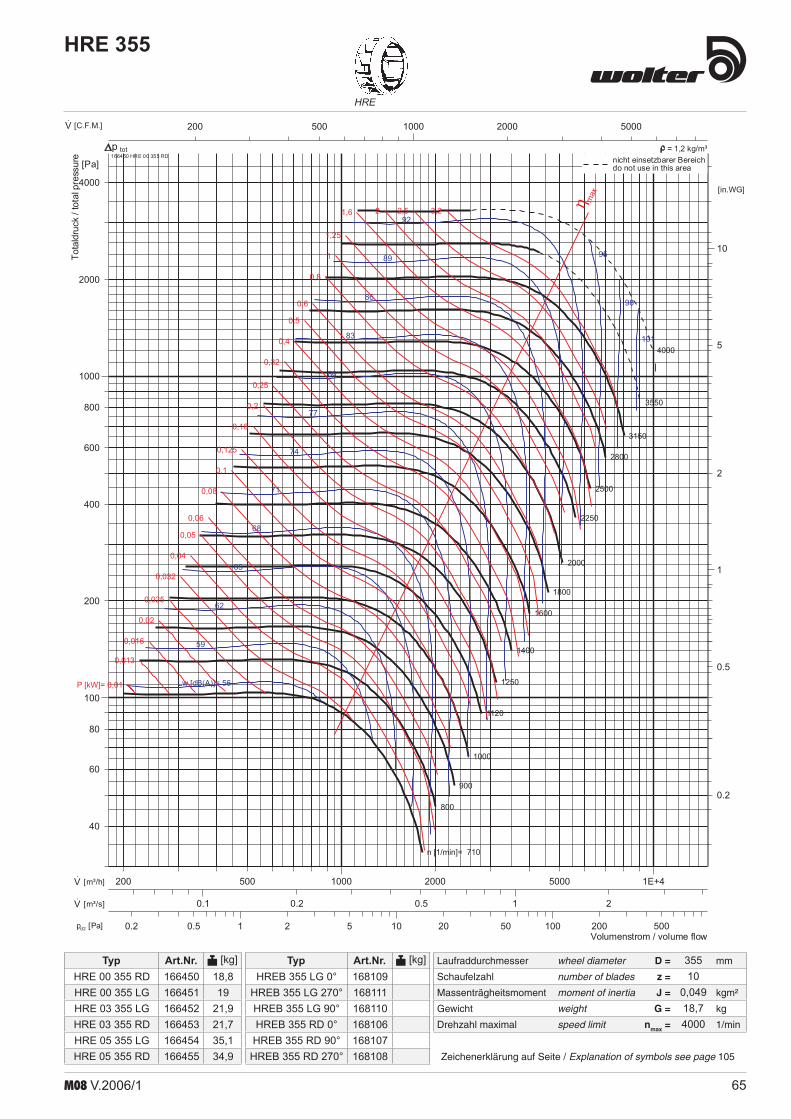
65M08 V.2006/1
HRE
Laufraddurchmesser wheel diameter D = mm
Schaufelzahl number of blades z =
Massenträgheitsmoment moment of inertia J = kgm²
Gewicht weight G = kg
Drehzahl maximal speed limit nmax = 1/min
Typ Art.Nr. [kg]
Zeichenerklärung auf Seite / Explanation of symbols see page 105
Typ Art.Nr. [kg]
HRE 355
1 10 1002 5 20 50 200 5000.50.2pd2 [Pa]
1000 2000 5000500200·V [C.F.M.]
0.1 10.2 0.5 2·V [m³/s]
1000 1E+42000 5000500200·V [m³/h]
1
10
2
5
0.5
0.2
[in.WG]
100
1000
200
400
600
800
2000
4000
80
60
40
[Pa]
n [1/min]= 710
800
900
1000
1120
1250
1400
1600
1800
2000
2250
2500
2800
3150
3550
4000
Lw [dB(A)]= 56
59
62
65
68
71
74
77
80
83
86
89
92
95
98
101
P [kW]= 0,01
0,013
0,016
0,02
0,025
0,032
0,04
0,05
0,06
0,08
0,1
0,125
0,16
0,2
0,25
0,32
0,4
0,5
0,6
0,8
1
1,25
1,6 2 2,5 3,2 η max
Volumenstrom / volume flow
Totaldruck/totalpressure 166450 HRE 00 355 RD
totnicht einsetzbarer Bereichdo not use in this area
p = 1,2 kg/m³
35510
0,04918,74000
HRE 00 355 RDHRE 00 355 LGHRE 03 355 LGHRE 03 355 RDHRE 05 355 LGHRE 05 355 RD
HREB 355 LG 0°HREB 355 LG 270°HREB 355 LG 90°HREB 355 RD 0°
HREB 355 RD 90°HREB 355 RD 270°
166450166451166452166453166454166455
168109168111168110168106168107168108
18,819
21,921,735,134,9

66 M08 V.2006/1
Laufraddurchmesser wheel diameter D = mm
Schaufelzahl number of blades z =
Massenträgheitsmoment moment of inertia J = kgm²
Gewicht weight G = kg
Drehzahl maximal speed limit nmax = 1/min
TRE
Typ Art.Nr. [kg]
Zeichenerklärung auf Seite / Explanation of symbols see page 105
Typ Art.Nr. [kg]
TRE 400
1 10 100 10002 5 20 50 200 500 20000.5pd2 [Pa]
1000 1E+42000 5000500200·V [C.F.M.]
0.1 10.2 0.5 2 5·V [m³/s]
1000 1E+42000 5000 2E+4500·V [m³/h]
1
10
2
5
0.5
[in.WG]
100
1000
200
400
600
800
2000
80
60
[Pa]
n [1/min]= 315
355
400
450
500
560
630
710
800
900
1000
1120
1250
1400
1600
1800
Lw [dB(A)]= 53
56
59
62
65
68
71
74
77
80
83
86
89
9295
98
P [kW]= 0,013
0,016
0,02
0,025
0,032
0,04
0,05
0,06
0,08
0,1
0,125
0,16
0,2
0,25
0,32
0,4
0,5
0,6
0,8
1
1,25
1,6
2
2,53,2 4
η max
Volumenstrom / volume flow
Totaldruck/totalpressure 165500 TRE 00 400 RD
totnicht einsetzbarer Bereichdo not use in this area
p = 1,2 kg/m³
40038
0,12526,81900
TRE 00 400 LGTRE 00 400 RDTRE 03 400 LGTRE 03 400 RDTRE 05 400 LGTRE 05 400 RD
TREB 400 LG 0°TREB 400 LG 270°TREB 400 LG 90°TREB 400 RD 0°
TREB 400 RD 90°TREB 400 RD 270°
165501165500165502165503165504165505
168016168018168017168013168014168015
25,626,828,629,836
37,8

67M08 V.2006/1
HRE
Laufraddurchmesser wheel diameter D = mm
Schaufelzahl number of blades z =
Massenträgheitsmoment moment of inertia J = kgm²
Gewicht weight G = kg
Drehzahl maximal speed limit nmax = 1/min
Typ Art.Nr. [kg]
Zeichenerklärung auf Seite / Explanation of symbols see page 105
Typ Art.Nr. [kg]
HRE 400
1 10 100 10002 5 20 50 200 5000.50.2pd2 [Pa]
1000 1E+42000 5000500200·V [C.F.M.]
0.1 10.2 0.5 2 5·V [m³/s]
1000 1E+42000 5000500·V [m³/h]
1
10
2
5
20
0.5
0.2
[in.WG]
100
1000
200
400
600
800
2000
4000
80
60
40
[Pa]
n [1/min]= 630
710
800
900
1000
1120
1250
1400
1600
1800
2000
2250
2500
2800
3150
3550
Lw [dB(A)]= 57
60
63
66
69
72
75
78
81
84
87
90
93
96
99
102
P [kW]= 0,013
0,016
0,02
0,025
0,032
0,04
0,05
0,06
0,08
0,1
0,125
0,16
0,2
0,25
0,32
0,4
0,5
0,6
0,8
1
1,25
1,6
2 2,5 3,2 4 5 η max
Volumenstrom / volume flow
Totaldruck/totalpressure 166500 HRE 00 400 RD
totnicht einsetzbarer Bereichdo not use in this area
p = 1,2 kg/m³
40010
0,0824,33500
HRE 00 400 LGHRE 00 400 RDHRE 03 400 LGHRE 03 400 RDHRE 05 400 LGHRE 05 400 RD
HREB 400 RD 0°HREB 400 RD 90°
HREB 400 RD 270°HREB 400 LG 0°
HREB 400 LG 90°HREB 400 LG 270°
166501166500166502166503166504166505
168112168113168114168115168116168117
26,422,429,425,437,433,4

68 M08 V.2006/1
Laufraddurchmesser wheel diameter D = mm
Schaufelzahl number of blades z =
Massenträgheitsmoment moment of inertia J = kgm²
Gewicht weight G = kg
Drehzahl maximal speed limit nmax = 1/min
TRE
Typ Art.Nr. [kg]
Zeichenerklärung auf Seite / Explanation of symbols see page 105
Typ Art.Nr. [kg]
TRE 450
1 10 100 10002 5 20 50 200 500 20000.5pd2 [Pa]
1000 1E+42000 5000 2E+4500·V [C.F.M.]
0.1 1 100.2 0.5 2 5·V [m³/s]
1000 1E+42000 5000 2E+4500·V [m³/h]
1
10
2
5
0.5
[in.WG]
100
1000
200
400
600
800
2000
80
60
[Pa]
n [1/min]= 280
315
355
400
450
500
560
630
710
800
900
1000
1120
1250
1400
1600
Lw [dB(A)]= 54
57
60
63
66
69
72
75
78
81
84
87
90
9396
99
P [kW]= 0,016
0,02
0,025
0,032
0,04
0,05
0,06
0,08
0,1
0,125
0,16
0,2
0,25
0,32
0,4
0,5
0,6
0,8
1
1,25
1,6
2
2,5
3,24 5
η max
Volumenstrom / volume flow
Totaldruck/totalpressure 165550 TRE 00 450 RD
totnicht einsetzbarer Bereichdo not use in this area
p = 1,2 kg/m³
45042
0,187530,51700
TRE 00 450 RDTRE 00 450 LGTRE 03 450 LGTRE 03 450 RDTRE 05 450 LGTRE 05 450 RD
TREB 450 LG 0°TREB 450 LG 270°TREB 450 LG 90°TREB 450 RD 0°
TREB 450 RD 90°TREB 450 RD 270°
165550165551165552165553165554165555
168022168024168023168019168020168021
36,436,240,841
49,249,4

69M08 V.2006/1
HRE
Laufraddurchmesser wheel diameter D = mm
Schaufelzahl number of blades z =
Massenträgheitsmoment moment of inertia J = kgm²
Gewicht weight G = kg
Drehzahl maximal speed limit nmax = 1/min
Typ Art.Nr. [kg]
Zeichenerklärung auf Seite / Explanation of symbols see page 105
Typ Art.Nr. [kg]
TRE 450
1 10 100 10002 5 20 50 200 5000.50.2pd2 [Pa]
1000 1E+42000 5000500200·V [C.F.M.]
0.1 10.2 0.5 2 5·V [m³/s]
1000 1E+42000 5000 2E+4500·V [m³/h]
1
10
2
5
20
0.5
0.2
[in.WG]
100
1000
200
400
600
800
2000
4000
80
60
40
[Pa]
n [1/min]= 560
630
710
800
900
1000
1120
1250
1400
1600
1800
2000
2250
2500
2800
3150
Lw [dB(A)]= 59
62
65
68
71
74
77
80
83
86
89
92
95
98
101
104
P [kW]= 0,016
0,02
0,025
0,032
0,04
0,05
0,06
0,08
0,1
0,125
0,16
0,2
0,25
0,32
0,4
0,5
0,6
0,8
1
1,25
1,6
2
2,53,2 4 5 6 8 η m
ax
Volumenstrom / volume flow
Totaldruck/totalpressure 166550 HRE 00 450 RD
totnicht einsetzbarer Bereichdo not use in this area
p = 1,2 kg/m³
45010
0,129527,83200
HRE 00 450 RDHRE 00 450 LGHRE 03 450 LGHRE 03 450 RDHRE 05 450 LGHRE 05 450 RD
HREB 450 LG 0°HREB 450 LG 270°HREB 450 LG 90°HREB 450 RD 0°
HREB 450 RD 90°HREB 450 RD 270°
166550166551166552166553166554166555
168121168123168122168118168119168120
3232,837,436,845,845

70 M08 V.2006/1
Laufraddurchmesser wheel diameter D = mm
Schaufelzahl number of blades z =
Massenträgheitsmoment moment of inertia J = kgm²
Gewicht weight G = kg
Drehzahl maximal speed limit nmax = 1/min
TRE
Typ Art.Nr. [kg]
Zeichenerklärung auf Seite / Explanation of symbols see page 105
Typ Art.Nr. [kg]
TRE 500
1 10 100 10002 5 20 50 200 500 20000.5pd2 [Pa]
1000 1E+42000 5000 2E+4500·V [C.F.M.]
1 102 50.50.2·V [m³/s]
1000 1E+42000 5000 2E+4500·V [m³/h]
1
10
2
5
0.5
0.2
[in.WG]
100
1000
200
400
600
800
2000
80
60
[Pa]
n [1/min]= 250
280
315
355
400
450
500
560
630
710
800
900
1000
1120
1250
1400
Lw [dB(A)]= 55
58
61
64
67
70
73
76
79
82
85
88
91
9497
P [kW]= 0,02
0,025
0,032
0,04
0,05
0,06
0,08
0,1
0,125
0,16
0,2
0,25
0,32
0,4
0,5
0,6
0,8
1
1,25
1,6
2
2,5
3,2 4 5
η max
Volumenstrom / volume flow
Totaldruck
/totalpressure 165600 TRE 00 500 RD
totnicht einsetzbarer Bereichdo not use in this area
p = 1,2 kg/m³
500380,4
44,11500
TRE 00 500 LGTRE 00 500 RDTRE 03 500 LGTRE 03 500 RDTRE 05 500 LGTRE 05 500 RD
TREB 500 RD 0°TREB 500 RD 90°
TREB 500 RD 270°TREB 500 LG 0°
TREB 500 LG 90°TREB 500 LG 270°
165601165600165602165603165604165605
168025168026168027168028168029168030
43,444,448,249,278,679,6

71M08 V.2006/1
HRE
Laufraddurchmesser wheel diameter D = mm
Schaufelzahl number of blades z =
Massenträgheitsmoment moment of inertia J = kgm²
Gewicht weight G = kg
Drehzahl maximal speed limit nmax = 1/min
Typ Art.Nr. [kg]
Zeichenerklärung auf Seite / Explanation of symbols see page 105
Typ Art.Nr. [kg]
HRE 500
1 10 100 10002 5 20 50 200 5000.50.2pd2 [Pa]
1000 1E+42000 5000500·V [C.F.M.]
0.1 10.2 0.5 2 5·V [m³/s]
1000 1E+42000 5000 2E+4500·V [m³/h]
1
10
2
5
20
0.5
0.2
[in.WG]
100
1000
200
400
600
800
2000
4000
80
60
40
[Pa]
n [1/min]= 500
560
630
710
800
900
1000
1120
1250
1400
1600
1800
2000
2250
2500
2800
Lw [dB(A)]= 59
62
65
68
71
74
77
80
83
86
89
92
95
98
101
104
P [kW]= 0,02
0,025
0,032
0,04
0,05
0,06
0,08
0,1
0,125
0,16
0,2
0,25
0,32
0,4
0,5
0,6
0,8
1
1,25
1,6
2
2,5
3,2 4 5 6 8 10
η max
Volumenstrom / volume flow
Totaldruck
/totalpressure 166600 HRE 00 500 RD
totnicht einsetzbarer Bereichdo not use in this area
p = 1,2 kg/m³
50010
0,27654,22800
HRE 00 500 LGHRE 00 500 RDHRE 03 500 LGHRE 03 500 RDHRE 05 500 LGHRE 05 500 RD
HREB 500 LG 0°HREB 500 LG 270°HREB 500 LG 90°HREB 500 RD 0°
HREB 500 RD 90°HREB 500 RD 270°
166601166600166602166603166604166605
168127168129168128168124168125168126
39,839,444,644,265
64,6

72 M08 V.2006/1
Laufraddurchmesser wheel diameter D = mm
Schaufelzahl number of blades z =
Massenträgheitsmoment moment of inertia J = kgm²
Gewicht weight G = kg
Drehzahl maximal speed limit nmax = 1/min
TRE
Typ Art.Nr. [kg]
Zeichenerklärung auf Seite / Explanation of symbols see page 105
Typ Art.Nr. [kg]
TRE 560
1 10 100 10002 5 20 50 200 5000.50.2pd2 [Pa]
1000 1E+42000 5000 2E+4500·V [C.F.M.]
1 102 50.50.2·V [m³/s]
1000 1E+42000 5000 2E+4 5E+4500·V [m³/h]
1
10
2
5
0.5
0.2
[in.WG]
100
1000
200
400
600
800
2000
80
60
[Pa]
n [1/min]= 200
225
250
280
315
355
400
450
500
560
630
710
800
900
1000
1120
Lw [dB(A)]= 53
56
59
62
65
68
71
74
77
80
83
86
89
9295
98
P [kW]= 0,02
0,025
0,032
0,04
0,05
0,06
0,08
0,1
0,125
0,16
0,2
0,25
0,32
0,4
0,5
0,6
0,8
1
1,25
1,6
2
2,5
3,24 5
6
η max
Volumenstrom / volume flow
Totaldruck
/totalpressure 165650 TRE 00 560 RD
totnicht einsetzbarer Bereichdo not use in this area
p = 1,2 kg/m³
56042
0,66561,41200
TRE 00 560 LGTRE 00 560 RDTRE 03 560 LGTRE 03 560 RDTRE 05 560 LGTRE 05 560 RD
TREB 560 LG 0°TREB 560 LG 270°TREB 560 LG 90°TREB 560 RD 0°
TREB 560 RD 90°TREB 560 RD 270°
165651165650165652165653165654165655
168034168036168035168031168032168033
60,660,667679090

73M08 V.2006/1
HRE
Laufraddurchmesser wheel diameter D = mm
Schaufelzahl number of blades z =
Massenträgheitsmoment moment of inertia J = kgm²
Gewicht weight G = kg
Drehzahl maximal speed limit nmax = 1/min
Typ Art.Nr. [kg]
Zeichenerklärung auf Seite / Explanation of symbols see page 105
Typ Art.Nr. [kg]
HRE 560
1 10 1002 5 20 50 200 5000.50.2pd2 [Pa]
1000 1E+42000 5000 2E+4500·V [C.F.M.]
1 102 50.50.2·V [m³/s]
1000 1E+42000 5000 2E+4500·V [m³/h]
1
10
2
5
20
0.5
0.2
[in.WG]
100
1000
200
400
600
800
2000
4000
80
60
40
[Pa]
n [1/min]= 450
500
560
630
710
800
900
1000
1120
1250
1400
1600
1800
2000
2250
2500
Lw [dB(A)]= 61
64
67
70
73
76
79
82
85
88
91
94
97
100
103
106
P [kW]= 0,025
0,032
0,04
0,05
0,06
0,08
0,1
0,125
0,16
0,2
0,25
0,32
0,4
0,5
0,6
0,8
1
1,25
1,6
2
2,5
3,2
4 5 6 8 10 12,5
η max
Volumenstrom / volume flow
Totaldruck
/totalpressure 166650 HRE 00 560 RD
totnicht einsetzbarer Bereichdo not use in this area
p = 1,2 kg/m³
56010
0,55871,92500
HRE 00 560 RDHRE 00 560 LGHRE 03 560 LGHRE 03 560 RDHRE 05 560 LGHRE 05 560 RD
HREB 560 RD 0°HREB 560 RD 90°
HREB 560 RD 270°HREB 560 LG 0°
HREB 560 LG 90°HREB 560 LG 270°
166650166651166652166653166654166655
168130168131168132168133168134168135
56,653,659,462,47070

74 M08 V.2006/1
Laufraddurchmesser wheel diameter D = mm
Schaufelzahl number of blades z =
Massenträgheitsmoment moment of inertia J = kgm²
Gewicht weight G = kg
Drehzahl maximal speed limit nmax = 1/min
TRE
Typ Art.Nr. [kg]
Zeichenerklärung auf Seite / Explanation of symbols see page 105
Typ Art.Nr. [kg]
TRE 630
1 10 100 10002 5 20 50 200 5000.50.2pd2 [Pa]
1000 1E+42000 5000 2E+4500·V [C.F.M.]
1 102 50.50.2·V [m³/s]
1000 1E+42000 5000 2E+4 5E+4·V [m³/h]
1
2
5
0.5
0.2
[in.WG]
100
1000
200
400
600
800
2000
80
60
40
[Pa]
n [1/min]= 160
180
200
225
250
280
315
355
400
450
500
560
630
710
800
900
Lw [dB(A)]= 52
55
58
61
64
67
70
73
76
79
82
85
88
9194
97
P [kW]= 0,016
0,02
0,025
0,032
0,04
0,05
0,06
0,08
0,1
0,125
0,16
0,2
0,25
0,32
0,4
0,5
0,6
0,8
1
1,25
1,6
2
2,53,2 4 5
6
η max
Volumenstrom / volume flow
Totaldruck/totalpressure 165700 TRE 00 630 RD
totnicht einsetzbarer Bereichdo not use in this area
p = 1,2 kg/m³
630 38
1,1574,8950
TRE 00 630 LGTRE 00 630 RDTRE 03 630 LGTRE 03 630 RDTRE 05 630 LGTRE 05 630 RD
TREB 630 LG 0°TREB 630 LG 270°TREB 630 LG 90°TREB 630 RD 0°
TREB 630 RD 90°TREB 630 RD 270°
165701165700165702165703165704165705
168040168042168041168037168038168039
7373
79,579,5101101

75M08 V.2006/1
HRE
Laufraddurchmesser wheel diameter D = mm
Schaufelzahl number of blades z =
Massenträgheitsmoment moment of inertia J = kgm²
Gewicht weight G = kg
Drehzahl maximal speed limit nmax = 1/min
Typ Art.Nr. [kg]
Zeichenerklärung auf Seite / Explanation of symbols see page 105
Typ Art.Nr. [kg]
HRE 630
1 10 100 10002 5 20 50 200 5000.50.2pd2 [Pa]
1000 1E+42000 5000 2E+4500·V [C.F.M.]
1 102 50.50.2·V [m³/s]
1000 1E+42000 5000 2E+4·V [m³/h]
1
10
2
5
20
0.5
0.2
[in.WG]
100
1000
200
400
600
800
2000
4000
80
60
40
[Pa]
n [1/min]= 400
450
500
560
630
710
800
900
1000
1120
1250
1400
1600
1800
2000
2250
Lw [dB(A)]= 62
65
68
71
74
77
80
83
86
89
92
95
98
101
104
107
P [kW]= 0,032
0,04
0,05
0,06
0,08
0,1
0,125
0,16
0,2
0,25
0,32
0,4
0,5
0,6
0,8
1
1,25
1,6
2
2,5
3,2
4
56 8 10 12,5 η m
ax
Volumenstrom / volume flow
Totaldruck/totalpressure 166700 HRE 00 630 RD
totnicht einsetzbarer Bereichdo not use in this area
p = 1,2 kg/m³
63010
0,80587,62200
HRE 00 630 LGHRE 00 630 RDHRE 03 630 LGHRE 03 630 RDHRE 05 630 LGHRE 05 630 RD
HREB 630 LG 0°HREB 630 LG 270°HREB 630 LG 90°HREB 630 RD 0°
HREB 630 RD 90°HREB 630 RD 270°
166701166700166702166703166704166705
168139168141168140168136168137168138
73,473,679,981,1
101,4101,6

76 M08 V.2006/1
Laufraddurchmesser wheel diameter D = mm
Schaufelzahl number of blades z =
Massenträgheitsmoment moment of inertia J = kgm²
Gewicht weight G = kg
Drehzahl maximal speed limit nmax = 1/min
TRE
Typ Art.Nr. [kg]
Zeichenerklärung auf Seite / Explanation of symbols see page 105
Typ Art.Nr. [kg]
TRE 710
1 10 100 10002 5 20 50 200 5000.50.2pd2 [Pa]
1000 1E+42000 5000 2E+4500·V [C.F.M.]
1 102 5 200.50.2·V [m³/s]
1000 1E+42000 5000 2E+4 5E+4·V [m³/h]
1
2
5
0.5
0.2
[in.WG]
100
1000
200
400
600
800
2000
80
60
40
[Pa]
n [1/min]= 140
160
180
200
225
250
280
315
355
400
450
500
560
630
710
800
Lw [dB(A)]= 53
56
59
62
65
68
71
74
77
80
83
86
89
9295
98
P [kW]= 0,02
0,025
0,032
0,04
0,05
0,06
0,08
0,1
0,125
0,16
0,2
0,25
0,32
0,4
0,5
0,6
0,8
1
1,25
1,6
2
2,5
3,24 5 6
810
η max
Volumenstrom / volume flow
Totaldruck/totalpressure 165757 TRE 07 710 RD
totnicht einsetzbarer Bereichdo not use in this area
p = 1,2 kg/m³
71042
1,875162850
TRE 07 710 LGTRE 07 710 RD
TREB 710 RD 0°TREB 710 RD 90°
TREB 710 RD 270°TREB 710 LG 0°
TREB 710 LG 90°TREB 710 LG 270°
165756165757
168043168044168045168046168047168048
162162

77M08 V.2006/1
HRE
Laufraddurchmesser wheel diameter D = mm
Schaufelzahl number of blades z =
Massenträgheitsmoment moment of inertia J = kgm²
Gewicht weight G = kg
Drehzahl maximal speed limit nmax = 1/min
Typ Art.Nr. [kg]
Zeichenerklärung auf Seite / Explanation of symbols see page 105
Typ Art.Nr. [kg]
HRE 710
0.1 1 10 1000.2 0.5 2 5 20 50 200 500pd2 [Pa]
1000 1E+42000 5000 2E+4500·V [C.F.M.]
1 102 50.50.2·V [m³/s]
1000 1E+42000 5000 2E+4·V [m³/h]
0.1
1
10
0.2
0.5
2
5[in.WG]
100
1000
200
400
600
800
2000
80
60
40
[Pa]
n [1/min]= 280
315
355
400
450
500
560
630
710
800
900
1000
1120
1250
1400
1600
Lw [dB(A)]= 58
61
64
67
70
73
76
79
82
85
88
91
94
97
100
103
P [kW]= 0,02
0,025
0,032
0,04
0,05
0,06
0,08
0,1
0,125
0,16
0,2
0,25
0,32
0,4
0,5
0,6
0,8
1
1,25
1,6
2
2,5
3,24 5 6 8 10 η m
ax
Volumenstrom / volume flow
Totaldruck/totalpressure 166757 HRE 07 710 RD
totnicht einsetzbarer Bereichdo not use in this area
p = 1,2 kg/m³
71010
1,3125182
1600
HRE 07 710 LGHRE 07 710 RD
HREB 710 LG 0°HREB 710 LG 270°HREB 710 LG 90°HREB 710 RD 0°
HREB 710 RD 90°HREB 710 RD 270°
166756166757
168145168147168146168142168143168144
150150
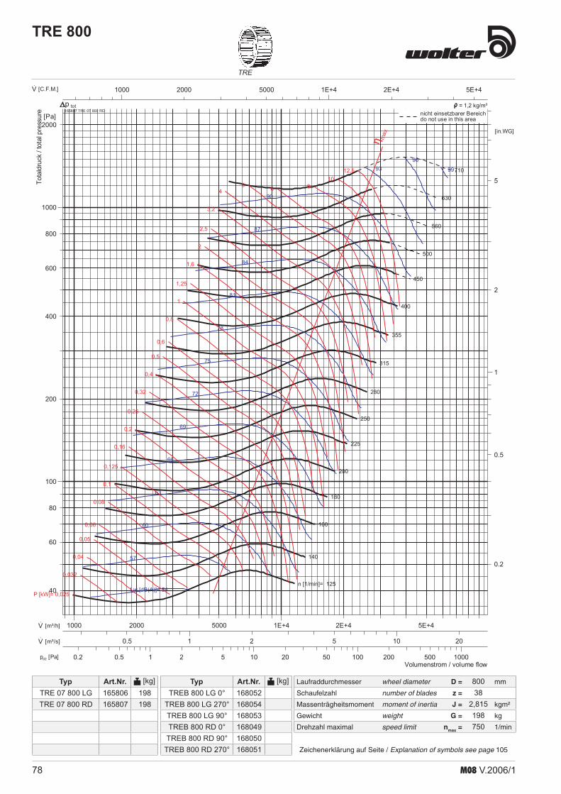
78 M08 V.2006/1
Laufraddurchmesser wheel diameter D = mm
Schaufelzahl number of blades z =
Massenträgheitsmoment moment of inertia J = kgm²
Gewicht weight G = kg
Drehzahl maximal speed limit nmax = 1/min
TRE
Typ Art.Nr. [kg]
Zeichenerklärung auf Seite / Explanation of symbols see page 105
Typ Art.Nr. [kg]
TRE 800
1 10 100 10002 5 20 50 200 5000.50.2pd2 [Pa]
1000 1E+42000 5000 2E+4 5E+4·V [C.F.M.]
1 102 5 200.5·V [m³/s]
1000 1E+42000 5000 2E+4 5E+4·V [m³/h]
1
2
5
0.5
0.2
[in.WG]
100
1000
200
400
600
800
2000
80
60
40
[Pa]
n [1/min]= 125
140
160
180
200
225
250
280
315
355
400
450
500
560
630
710
Lw [dB(A)]= 54
57
60
63
66
69
72
75
78
81
84
87
90
9396
99
P [kW]= 0,025
0,032
0,04
0,05
0,06
0,08
0,1
0,125
0,16
0,2
0,25
0,32
0,4
0,5
0,6
0,8
1
1,25
1,6
2
2,5
3,2
45 6 8
1012,5
η max
Volumenstrom / volume flow
Totaldruck/totalpressure 165807 TRE 07 800 RD
totnicht einsetzbarer Bereichdo not use in this area
p = 1,2 kg/m³
80038
2,815198750
TRE 07 800 LGTRE 07 800 RD
TREB 800 LG 0°TREB 800 LG 270°TREB 800 LG 90°TREB 800 RD 0°
TREB 800 RD 90°TREB 800 RD 270°
165806165807
168052168054168053168049168050168051
198198

79M08 V.2006/1
HRE
Laufraddurchmesser wheel diameter D = mm
Schaufelzahl number of blades z =
Massenträgheitsmoment moment of inertia J = kgm²
Gewicht weight G = kg
Drehzahl maximal speed limit nmax = 1/min
Typ Art.Nr. [kg]
Zeichenerklärung auf Seite / Explanation of symbols see page 105
Typ Art.Nr. [kg]
HRE 800
0.1 1 10 1000.2 0.5 2 5 20 50 200 500pd2 [Pa]
1000 1E+42000 5000 2E+4500·V [C.F.M.]
1 102 50.5·V [m³/s]
1000 1E+42000 5000 2E+4 5E+4·V [m³/h]
0.1
1
10
0.2
0.5
2
5
[in.WG]
100
1000
200
400
600
800
2000
80
60
40
[Pa]
n [1/min]= 250
280
315
355
400
450
500
560
630
710
800
900
1000
1120
1250
1400
Lw [dB(A)]= 59
62
65
68
71
74
77
80
83
86
89
92
95
98
101
104
P [kW]= 0,025
0,032
0,04
0,05
0,06
0,08
0,1
0,125
0,16
0,2
0,25
0,32
0,4
0,5
0,6
0,8
1
1,25
1,6
2
2,5
3,2
45 6 8 10 η m
ax
Volumenstrom / volume flow
Totaldruck/totalpressure 166807 HRE 07 800 RD
totnicht einsetzbarer Bereichdo not use in this area
p = 1,2 kg/m³
8010
1,9705201
1400
HRE 07 800 LGHRE 07 800 RD
HREB 800 RD 0°HREB 800 RD 90°
HREB 800 RD 270°HREB 800 LG 0°
HREB 800 LG 90°HREB 800 LG 270°
166806166807
168148168149168150168151168152168153
195195

80 M08 V.2006/1
Laufraddurchmesser wheel diameter D = mm
Schaufelzahl number of blades z =
Massenträgheitsmoment moment of inertia J = kgm²
Gewicht weight G = kg
Drehzahl maximal speed limit nmax = 1/min
TRE
Typ Art.Nr. [kg]
Zeichenerklärung auf Seite / Explanation of symbols see page 105
Typ Art.Nr. [kg]
TRE 900
1 10 100 10002 5 20 50 200 5000.50.2pd2 [Pa]
1000 1E+42000 5000 2E+4 5E+4·V [C.F.M.]
1 102 5 200.5·V [m³/s]
1E+4 1E+52E+4 5E+450002000·V [m³/h]
1
2
5
0.5
0.2
[in.WG]
100
1000
200
400
600
800
2000
80
60
40
[Pa]
n [1/min]= 112
125
140
160
180
200
225
250
280
315
355
400
450
500
560
630
Lw [dB(A)]= 55
58
61
64
67
70
73
76
79
82
85
88
91
9497
100
P [kW]= 0,032
0,04
0,05
0,06
0,08
0,1
0,125
0,16
0,2
0,25
0,32
0,4
0,5
0,6
0,8
1
1,25
1,6
2
2,5
3,2
4
56
8 1012,5
16
η max
Volumenstrom / volume flow
Totaldruck
/totalpressure 165857 TRE 07 900 RD
totnicht einsetzbarer Bereichdo not use in this area
p = 1,2 kg/m³
90042
4,435246650
TRE 07 900 LGTRE 07 900 RD
TREB 900 LG 0°TREB 900 LG 270°TREB 900 LG 90°TREB 900 RD 0°
TREB 900 RD 90°TREB 900 RD 270°
165856165857
168058168060168059168055168056168057
246246

81M08 V.2006/1
HRE
Laufraddurchmesser wheel diameter D = mm
Schaufelzahl number of blades z =
Massenträgheitsmoment moment of inertia J = kgm²
Gewicht weight G = kg
Drehzahl maximal speed limit nmax = 1/min
Typ Art.Nr. [kg]
Zeichenerklärung auf Seite / Explanation of symbols see page 105
Typ Art.Nr. [kg]
HRE 900
1 10 1002 5 20 50 200 5000.50.2pd2 [Pa]
1000 1E+42000 5000 2E+4 5E+4·V [C.F.M.]
1 102 5 200.5·V [m³/s]
1E+4 2E+4 5E+450002000·V [m³/h]
0.1
1
10
0.2
0.5
2
5
[in.WG]
100
1000
200
400
600
800
2000
4000
80
60
40
20
[Pa]
n [1/min]= 250280
315
355
400
450
500560
630
710
800
900
10001120
1250
1400
Lw [dB(A)]= 63
66
69
72
75
78
81
84
87
90
93
96
99
102
105
108
P [kW]= 0,05
0,06
0,08
0,1
0,125
0,16
0,2
0,25
0,32
0,4
0,5
0,6
0,8
1
1,25
1,6
2
2,5
3,2
4
5
6
8 10 12,5 16 2025
η max
Volumenstrom / volume flow
Totaldruck
/totalpressure 166857 HRE 07 900 RD
totnicht einsetzbarer Bereichdo not use in this area
p = 1,2 kg/m³
90010
3,1045273
1400
HRE 07 900 LGHRE 07 900 RD
HREB 900 LG 0°HREB 900 LG 270°HREB 900 LG 90°HREB 900 RD 0°
HREB 900 RD 90°HREB 900 RD 270°
166856166857
168157168159168158168154168155168156
240240

82 M08 V.2006/1
Laufraddurchmesser wheel diameter D = mm
Schaufelzahl number of blades z =
Massenträgheitsmoment moment of inertia J = kgm²
Gewicht weight G = kg
Drehzahl maximal speed limit nmax = 1/min
TRE
Typ Art.Nr. [kg]
Zeichenerklärung auf Seite / Explanation of symbols see page 105
Typ Art.Nr. [kg]
TRE 1000
1 10 100 10002 5 20 50 200 5000.50.2pd2 [Pa]
1000 1E+42000 5000 2E+4 5E+4·V [C.F.M.]
1 102 5 200.5·V [m³/s]
1E+4 1E+52E+4 5E+450002000·V [m³/h]
1
2
5
0.5
0.2
[in.WG]
100
1000
200
400
600
800
2000
80
60
40
[Pa]
n [1/min]= 100
112
125
140
160
180
200
225
250
280
315
355
400
450
500
560
Lw [dB(A)]= 56
59
62
65
68
71
74
77
80
83
86
89
92
9598
101
P [kW]= 0,04
0,05
0,06
0,08
0,1
0,125
0,16
0,2
0,25
0,32
0,4
0,5
0,6
0,8
1
1,25
1,6
2
2,5
3,2
4
5
68 10 12,5
1620
η max
Volumenstrom / volume flow
Totaldruck/totalpressure 165907 TRE 07 1000 RD
totnicht einsetzbarer Bereichdo not use in this area
p = 1,2 kg/m³
TRE 07 1000 LGTRE 07 1000 RD
165906165907
288288
100048
7,35288600
TREB 1000 LG 0°TREB 1000 LG 270°TREB 1000 LG 90°TREB 1000 RD 0°
TREB 1000 RD 90°TREB 1000 RD 270°
168064168066168065168061168062168063

83M08 V.2006/1
HRE
Laufraddurchmesser wheel diameter D = mm
Schaufelzahl number of blades z =
Massenträgheitsmoment moment of inertia J = kgm²
Gewicht weight G = kg
Drehzahl maximal speed limit nmax = 1/min
Typ Art.Nr. [kg]
Zeichenerklärung auf Seite / Explanation of symbols see page 105
Typ Art.Nr. [kg]
HRE 1000
1 10 100 10002 5 20 50 200 5000.50.2pd2 [Pa]
1000 1E+42000 5000 2E+4 5E+4·V [C.F.M.]
1 102 5 200.5·V [m³/s]
1E+4 1E+52E+4 5E+450002000·V [m³/h]
0.1
1
10
0.2
0.5
2
5
20
[in.WG]
100
1000
200
400
600
800
2000
4000
80
60
40
[Pa]
n [1/min]= 250280
315
355
400
450
500560
630
710
800
900
10001120
1250
1400
Lw [dB(A)]= 66
69
72
75
78
81
84
87
90
93
96
99
102
105
108
111
P [kW]= 0,08
0,1
0,125
0,16
0,2
0,25
0,32
0,4
0,5
0,6
0,8
1
1,25
1,6
2
2,5
3,2
4
5
6
8
10
12,5 16 20 η max
Volumenstrom / volume flow
Totaldruck/totalpressure 166907 HRE 07 1000 RD
totnicht einsetzbarer Bereichdo not use in this area
p = 1,2 kg/m³
10010
5,145331
1300
HRE 07 1000 LGHRE 07 1000 RD
HREB 1000 RD 0°HREB 1000 RD 90°
HREB 1000 RD 270°HREB 1000 LG 0°
HREB 1000 LG 90°HREB 1000 LG 270°
166906166907
168160168161168162168163168164168165
331331

84 M08 V.2006/1
HRETRE
Maß- und Konstruktionsänderungen, dem technischen Fortschritt dienend, bleiben uns vorbehalten.We reserve the right to alter measurements without notice in case of technical improvements .
AbmessungenDimensionsTRE, HRE
freies Wellenende
nutzbares Wellenende
n
f
h6d
h
p
A3 B3
C3
H1
H2
L5L6
H6
H5
Baugröße A A3 B B3 C C1 C2 C3 d H1 H2 H5 H6 h L5 L6 n p ØZ size [mm] [mm] [mm] [mm] [mm] [mm] [mm] [mm] [mm] [mm] [mm] [mm] [mm] [mm] [mm] [mm] [mm] [mm] [mm] 160 200 202 100 102 229 345 20 128 183 71 125 22,5 302 150 45 6 7 180 224 226 112 114 253 390 20 143 204 81 142 22,5 333 163 55 6 7 200 250 252 125 127 279 425 207,5 232,5 20 157 226 89 157 22,5 363 175 60 6 7 225 280 282 140 142 309 455 225 250 20 176 253 101 177 22,5 401 191 60 6 7 250 315 317 158 160 344 490 245 270 20 194 279 111 196 22,5 438 207 60 6 7 280 355 357 178 180 389 525 275 300 25 216 312 123 220 28 483 225 57 8 10 315 400 402 200 202 434 565 295 320 25 241 350 138 246 28 536 247 55 8 10 355 450 452 225 227 494 655 335 360 30 271 393 156 279 33 597 272 69 8 10 400 500 502 250 252 544 710 363 388 30 304 441 180 315 33 666 302 74 8 10 450 560 562 280 282 604 780 405 430 35 341 495 204 354 38 742 333 76 10 12 500 630 632 315 317 674 860 440,5 465,5 35 377 549 222 393 38 815 363 81 10 12 560 710 712 355 357 764 975 509,5 534,5 40 421 613 247 440 43 911 405 95 12 15 630 800 802 400 402 854 1065 554,0 579 40 473 689 278 493 43 1017 449 95 12 15 710 900 902 450 452 964 1210 619 644 50 532 775 314 552 53,3 1138 499 117 14 17
TRE 00HRE 00
RD = rechtsdrehend/ clockwise LG = linksdrehend/ anti-clockwise
Der Drehsinn wird durch Blick von der Antriebsseite bestimmt. / The direction of rotation is defined by vue on the side of drive .
RD 0 RD 90 RD 180 RD 270 LG 0 LG 90 LG 180 LG 270
AbmessungenDimensionsTRE, HRE

85M08 V.2006/1
HRETRE
Maß- und Konstruktionsänderungen, dem technischen Fortschritt dienend, bleiben uns vorbehalten.We reserve the right to alter measurements without notice in case of technical improvements
AbmessungenDimensionsTRE, HRE
freies Wellenende
nutzbares Wellenende
n
f
h6d
h
p
ØZ
AA1
A2 B
B2
B1
fx12
5e
e1 f1x1
25
C2C3
L1
L3
H
H2
L7
H1
ØZL
H5
H8
H6
H9
Baugröße A A1 A2 A3 B B1 B2 C C1 C2 C3 d e e1 f fx125 f1x125 size [mm] [mm] [mm] [mm] [mm] [mm] [mm] [mm] [mm] [mm] [mm] [mm] [mm] [mm] [mm] 160 200 226 256 202 229 345 20 113 40 - - 180 224 250 280 226 253 390 20 125 40 - - 200 250 276 306 252 125 151 181 279 425 154 232,5 20 138 75,5 40 - - 225 280 306 336 282 140 166 196 309 455 169 250 20 153 133 40 - - 250 315 341 371 317 160 186 216 344 490 189 270 20 108 93 40 2 - 280 355 381 411 357 180 206 236 389 525 214 300 25 128 103 50 2 - 315 400 426 456 402 200 226 256 434 565 234 320 25 150,5 113 50 2 - 355 450 476 506 452 224 250 280 494 655 268 360 30 50,5 125 60 3 - 400 500 526 556 502 250 276 306 544 710 294 388 30 75,5 138 60 3 - 450 560 586 616 562 280 306 336 604 780 324 430 35 105,5 153 65 3 - 500 630 656 686 632 315 341 371 674 860 359 465,5 35 140,5 108 65 3 2 560 710 736 766 712 355 381 411 764 975 409 534,5 40 55,6 128 80 5 2 630 800 826 856 802 400 426 456 854 1065 454 579 40 100,5 150,5 80 5 2 710 900 926 956 902 964 1210 514 50 150,5 100 5
TRE 03HRE 03
Baugröße H H1 H2 H5 H6 H8 H9 h L L1 L3 L7 n p ØZ size [mm] [mm] [mm] [mm] [mm] [mm] [mm] [mm] [mm] [mm] [mm] [mm] [mm] [mm] [mm] [mm] 160 359 128 183 71 125 158 212 22,5 180 154 306 158 45 6 7 180 394 143 204 81 142 172 232 22,5 180 167 337 172 55 6 7 200 433 157 226 89 157 189 253 22,5 214 179 367 192 60 6 7 225 476 176 253 101 177 205 282 22,5 214 195 405 212 60 6 7 250 515 194 279 111 196 218 307 22,5 214 211 442 235 60 6 7 280 573 216 312 123 220 243 338 28 280 229 487 262 57 8 10 315 635 241 350 138 246 268 377 28 280 251 540 290 55 8 10 355 692 271 393 156 279 281 418 33 355 276 601 327 69 8 10 400 768 304 441 180 315 309 469 33 355 306 670 366 74 8 10 450 879 341 495 204 354 346 528 38 450 337 746 415 76 10 12 500 951 377 549 222 393 385 578 38 450 367 819 458 81 10 12 560 1055 421 613 247 440 424 642 43 500 409 915 510 95 12 15 630 1182 473 689 278 493 476 715 43 560 453 1021 579 95 12 15 710 1334 532 775 314 552 541 807 53,3 630 503 1142 646 117 14 17

86 M08 V.2006/1
HRETRE
Maß- und Konstruktionsänderungen, dem technischen Fortschritt dienend, bleiben uns vorbehalten.We reserve the right to alter measurements without notice in case of technical improvements .
AbmessungenDimensionsTRE, HRE
freies Wellenende
nutzbares Wellenende
n
f
h6d
h
p
ØZ
AA1
A2 B
B2
B1
fx12
5e
e1 f1x1
25
C3
C2C5
L1L3
H4
H2
H1
H6
H5
H
L4 L2
L5 L
H7
TRE 05HRE 05
Baugröße A A1 A2 A3 B B1 B2 C C1 C2 C3 C4 C5 C6 d e e1 size [mm] [mm] [mm] [mm] [mm] [mm] [mm] [mm] [mm] [mm] [mm] [mm] [mm] [mm] [mm] [mm] [mm] 200 250 276 306 252 125 151 181 279 425 154 232,5 179 425 20 138 75,5 225 280 306 336 282 140 166 196 309 455 169 250 194 334 20 153 133 250 315 341 371 317 160 186 216 344 490 189 270 214 369 20 108 93 280 355 381 411 357 180 206 236 389 525 214 300 244 419 25 128 103 315 400 426 456 402 200 226 256 434 565 234 320 264 464 25 150,5 113 355 450 476 506 452 224 250 280 494 655 268 360 308 534 30 50,5 125 400 500 526 556 502 250 276 306 544 710 294 388 334 584 30 75,5 138 450 560 586 616 562 280 306 336 604 780 324 430 364 640 35 105,5 153 500 630 656 686 632 315 341 371 674 860 359 465,5 399 714 35 140,5 108 560 710 736 766 712 355 381 411 764 975 409 534,5 459 814 40 55,6 128 630 800 826 856 802 400 426 456 854 1065 454 579 504 904 40 100,5 150,5 710 900 926 956 902 450 476 506 964 1210 514 664,0 554 1004 50 150,5 50,5
Baugröße f fx125 f1x125 H H1 H2 H3 H4 H5 H6 H7 h L L1 L2 L3 L4 L5 n p ØZ size [mm] [mm] [mm] [mm] [mm] [mm] [mm] [mm] [mm] [mm] [mm] [mm] [mm] [mm] [mm] [mm] [mm] [mm] [mm] 200 40 - - 400 157 226 224 89 157 80 23 224 179 188 367 132 48 60 6 7 225 40 - - 446 176 253 224 101 177 103 23 224 195 210 405 146 66 60 6 7 250 40 2 - 491 194 279 224 111 196 125 23 224 211 231 442 161 84 60 6 7 280 50 2 - 545 216 312 280 123 220 124 28 280 229 258 487 185 82 57 8 10 315 50 2 - 608 241 350 280 138 246 156 28 280 251 289 540 204 107 55 8 10 355 60 3 - 681 271 393 355 156 279 155 33 355 276 325 601 227 99 69 8 10 400 60 3 - 762 304 441 355 180 315 195 33 355 306 366 670 249 130 74 8 10 450 65 3 - 854 341 495 450 204 354 193 38 450 337 409 746 273 116 76 10 12 500 65 3 2 943 377 549 450 222 393 238 38 450 367 452 819 300 151 81 10 12 560 80 5 2 1052 421 613 500 247 440 267 43 500 409 506 915 337 172 95 12 15 630 80 5 2 1179 473 689 560 278 493 301 43 560 453 568 1021 370 189 95 12 15 710 100 5 3 1324 532 775 630 314 552 339 53 630 503 639 1142 413 211 117 14 17
RD = rechtsdrehend/ clockwise LG = linksdrehend/ anti-clockwise
Der Drehsinn wird durch Blick von der Antriebsseite bestimmt. / The direction of rotation is defined by vue on the side of drive .
RD 0 RD 90 RD 180 RD 270 LG 0 LG 90 LG 180 LG 270

87M08 V.2006/1
HRETRE
Maß- und Konstruktionsänderungen, dem technischen Fortschritt dienend, bleiben uns vorbehalten.We reserve the right to alter measurements without notice in case of technical improvements
AbmessungenDimensionsTRE, HRE
freies Wellenende
nutzbares Wellenende
n
f
h6d
h
p
A3
ØZ
B3
C2C5
L5
H4
H2
H1
H
H6
H5
L
L4 L2
H7
A3
L1
L3TRE 06HRE 06
Baugröße A A1 A2 A3 B B1 B2 C C1 C2 C3 C4 C5 C6 d e e1 size [mm] [mm] [mm] [mm] [mm] [mm] [mm] [mm] [mm] [mm] [mm] [mm] [mm] [mm] [mm] [mm] [mm] 710 900 926 956 902 450 476 506 964 1250 514 644 554 1004 50 150,5 50,5 800 1000 1026 1056 1002 500 526 556 1064 1360 564 695 604 1104 50 75,5 105,5 900 1120 1146 1176 1122 560 586 616 1184 1495 624 785 664 1224 60 135,5 105,5 1000 1250 1276 1306 1252 630 656 686 1314 1630 694 854 734 1354 60 75,5 138
Baugröße fx125 f1x125 H H1 H2 H3 H4 H5 H6 H7 h L L1 L2 L3 L4 L5 n p ØZ size [mm] [mm] [mm] [mm] [mm] [mm] [mm] [mm] [mm] [mm] [mm] [mm] [mm] [mm] [mm] [mm] [mm] [mm] 710 5 3 1324 532 775 630 314 522 339 53,5 630 503 639 1142 413 211 110 14 18 800 7 3 1486 597 872 710 361 629 380 53,5 710 562 718 1280 454 231 115 14 18 900 7 3 1668 671 980 800 409 710 426 64 800 627 807 1434 502 255 116 18 18 1000 9 3 1827 736 1076 900 440 779 456 64 900 679 886 1565 556 271 118 18 18
freies Wellenende
nutzbares Wellenende
n
f
h6d
h
p
ØZ
AA1
A2 B
B2
B1
fx12
5e
e1 f1x1
25
C3
C2C5L5
H4
H2
H1
H
H6
H5
L
L4 L2
H7
H
L1
L3
TRE 07HRE 07
Baugröße A A1 A2 A3 B B1 B2 C C1 C2 C3 C4 C5 C6 d e e1 size [mm] [mm] [mm] [mm] [mm] [mm] [mm] [mm] [mm] [mm] [mm] [mm] [mm] [mm] [mm] [mm] [mm] 710 900 926 956 902 450 476 506 964 1250 514 644 554 1004 50 150,5 50,5 800 1000 1026 1056 1002 500 526 556 1064 1360 564 695 604 1104 50 75,5 105,5 900 1120 1146 1176 1122 560 586 616 1184 1495 624 785 664 1224 60 135,5 105,5 1000 1250 1276 1306 1252 630 656 686 1314 1630 694 854 734 1354 60 75,5 138
Baugröße fx125 f1x125 H H1 H2 H3 H4 H5 H6 H7 h L L1 L2 L3 L4 L5 n p ØZ size [mm] [mm] [mm] [mm] [mm] [mm] [mm] [mm] [mm] [mm] [mm] [mm] [mm] [mm] [mm] [mm] [mm] [mm] 710 5 3 1324 532 775 630 314 522 339 53,5 630 503 639 1142 413 211 110 14 18 800 7 3 1486 597 872 710 361 629 380 53,5 710 562 718 1280 454 231 115 14 18 900 7 3 1668 671 980 800 409 710 426 64 800 627 807 1434 502 255 116 18 18 1000 9 3 1827 736 1076 900 440 779 456 64 900 679 886 1565 556 271 118 18 18

88 M08 V.2006/1
HRETRE
Maß- und Konstruktionsänderungen, dem technischen Fortschritt dienend, bleiben uns vorbehalten.We reserve the right to alter measurements without notice in case of technical improvements .
AbmessungenDimensionsTRE, HRE
Baugröße max.Motor L e1 e2 H BE CE x1 y d H1 H2 H3 G W
size max. motor [mm] [mm] [mm] [mm] [mm] [mm] [mm] [mm] [mm] [mm] [mm] [mm] [mm] [mm] [kg] 200 112M 640 170 230 108 183 155 658 14 10,5 133 189 278 179 310 4,5 225 112M 640 170 230 108 198 170 658 14 10,5 133 205 306 195 320 5,0 250 132S 640 170 230 108 218 190 658 14 10,5 133 218 329 211 340 5,8 280 132S 750 207 243 105 242 212 768 15 10,5 130 243 366 229 400 7,0 315 132S 750 207 243 105 262 232 768 15 10,5 130 268 406 241 415 7,3 355 132S 880 250 260 133 306 266 918 20 12 158 281 437 276 480 14,4 400 132S 880 250 260 133 332 292 918 20 12 158 309 489 306 505 14,8 450 132S 1065 300 300 188 362 322 1103 20 12 213 346 550 337 590 16,5 500 132S 1065 300 300 188 397 357 1103 20 12 213 385 607 367 600 17,0
Grundrahmen mit MotorwippeBase frame with motor bracket
CEBE
W G
H2
H3
HH1
e1
L
x1
d
RD = rechtsdrehend/ clockwise LG = linksdrehend/ anti-clockwise
Der Drehsinn wird durch Blick von der Antriebsseite bestimmt. / The direction of rotation is defined by vue on the side of drive .
RD 0 RD 90 RD 180 RD 270 LG 0 LG 90 LG 180 LG 270
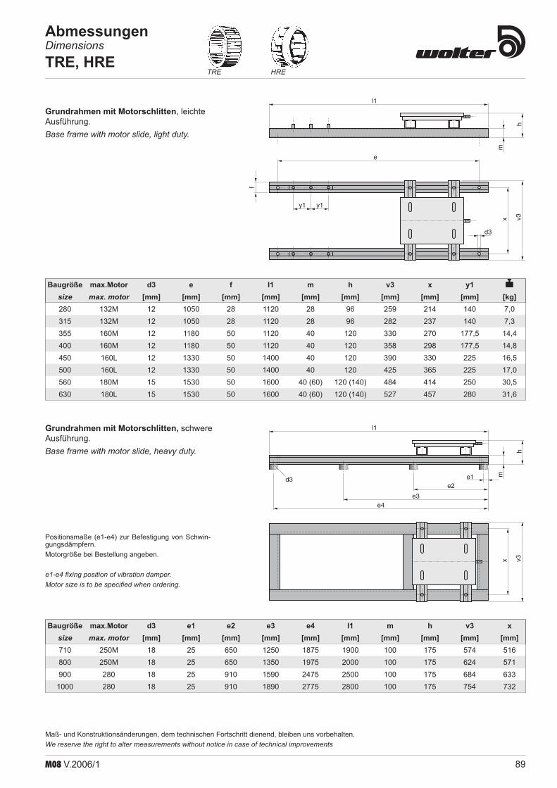
89M08 V.2006/1
HRETRE
Maß- und Konstruktionsänderungen, dem technischen Fortschritt dienend, bleiben uns vorbehalten.We reserve the right to alter measurements without notice in case of technical improvements
AbmessungenDimensionsTRE, HRE
hv3x
l1
me1e2
e3e4
d3
Baugröße max.Motor d3 e1 e2 e3 e4 l1 m h v3 x size max. motor [mm] [mm] [mm] [mm] [mm] [mm] [mm] [mm] [mm] [mm] 710 250M 18 25 650 1250 1875 1900 100 175 574 516 800 250M 18 25 650 1350 1975 2000 100 175 624 571 900 280 18 25 910 1590 2475 2500 100 175 684 633 1000 280 18 25 910 1890 2775 2800 100 175 754 732
Positionsmaße (e1-e4) zur Befestigung von Schwin-gungsdämpfern.Motorgröße bei Bestellung angeben.
e1-e4 fixing position of vibration damper.Motor size is to be specified when ordering.
hv3x
d3
e
y1 y1
l1
m
f
Baugröße max.Motor d3 e f l1 m h v3 x y1
size max. motor [mm] [mm] [mm] [mm] [mm] [mm] [mm] [mm] [mm] [kg] 280 132M 12 1050 28 1120 28 96 259 214 140 7,0 315 132M 12 1050 28 1120 28 96 282 237 140 7,3 355 160M 12 1180 50 1120 40 120 330 270 177,5 14,4 400 160M 12 1180 50 1120 40 120 358 298 177,5 14,8 450 160L 12 1330 50 1400 40 120 390 330 225 16,5 500 160L 12 1330 50 1400 40 120 425 365 225 17,0 560 180M 15 1530 50 1600 40 (60) 120 (140) 484 414 250 30,5 630 180L 15 1530 50 1600 40 (60) 120 (140) 527 457 280 31,6
Grundrahmen mit Motorschlitten, leichte Ausführung.Base frame with motor slide, light duty .
Grundrahmen mit Motorschlitten, schwere Ausführung.Base frame with motor slide, heavy duty .

90 M08 V.2006/1
HRETRE
Maß- und Konstruktionsänderungen, dem technischen Fortschritt dienend, bleiben uns vorbehalten.We reserve the right to alter measurements without notice in case of technical improvements .
AbmessungenDimensionsTRE, HRE
x
v3
m h
l 2
Baugröße max.Motor l2 h m v3 x
size max. motor [mm] [mm] [mm] [mm] [mm] [kg] 200 90S 313 89 28 199 157 1,8 225 90L 348 89 28 214 172 2,0 250 100L 384 89 28 234 190 2,2 280 100L 433 89 28 264 214 4,1 315 100L 481 89 28 284 237 4,5 355 112M 541 89 28 328 270 9,0 400 112M 606 89 28 354 298 10,0 450 132S 674 160 40 384 330 11,0 500 132M 743 160 40 419 365 12,2 560 160M 837 160 40 497 414 21,5 630 160M 935 160 40 524 457 23,8 710 160L 1049 184 60 574 516 33,5 800 180M 1174 184 60 624 571 37,2 900 180L 1313 184 60 684 633 41,2 1000 200L 1444 184 60 754 732 45,5
Motorbefestigung RechteckrahmenScroll mounted base frame

91M08 V.2006/1
HRETRE
Maß- und Konstruktionsänderungen, dem technischen Fortschritt dienend, bleiben uns vorbehalten.We reserve the right to alter measurements without notice in case of technical improvements
AbmessungenDimensionsTRE, HRE
m m
m
n
f1 f2
h2h1
f4
h4
h3
f3RD (GL)
360°RD (GL)
270°RD (GL)
90°
e
a
15b
c
d
Baugröße max. Motor b c d e f1 f2 f3 f4 h1 h2 h3 h4 m n size max. motor [mm] [mm] [mm] [mm] [mm] [mm] [mm] [mm] [mm] [mm] [mm] [mm] [mm] [mm] 160 71 60 15 7,5 10 155 101 101 215 146 176 30 30 180 80 60 15 7,5 10 175 115 115 235 175 190 30 30 200 80 60 15 7,5 10 190 126 129 250 186 204 40 40 225 90S 60 15 7,5 10 219 142 149 279 202 224 40 40 260 90S 60 15 7,5 10 244 155 172 304 215 247 40 40 280 90L 80 20 10 14 245 170 169 345 250 269 113 71 315 100L 80 20 10 14 284 195 197 384 275 297 113 71 355 100L 80 20 10 14 295 158 204 395 258 304 156 156 400 100L 80 20 10 14 346 186 243 446 286 343 156 156 450 112M 100 20 12 14 350 168 271 450 268 371 213 213 500 112M 100 20 12 14 400 207 280 520 327 400 213 213
MotorwippeMotor bracket
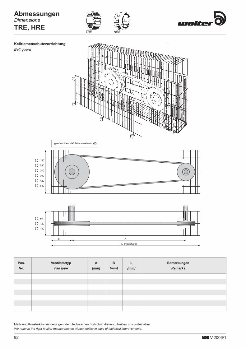
92 M08 V.2006/1
HRETRE
Maß- und Konstruktionsänderungen, dem technischen Fortschritt dienend, bleiben uns vorbehalten.We reserve the right to alter measurements without notice in case of technical improvements .
AbmessungenDimensionsTRE, HRE
B A
L (max.2000)
180
240
300
360
420
540
80
120
140
gewünschtes Maß bitte markieren
KeilriemenschutzvorrichtungBelt guard
Pos. Ventilatortyp A B L Bemerkungen No. Fan type [mm] [mm] [mm] Remarks
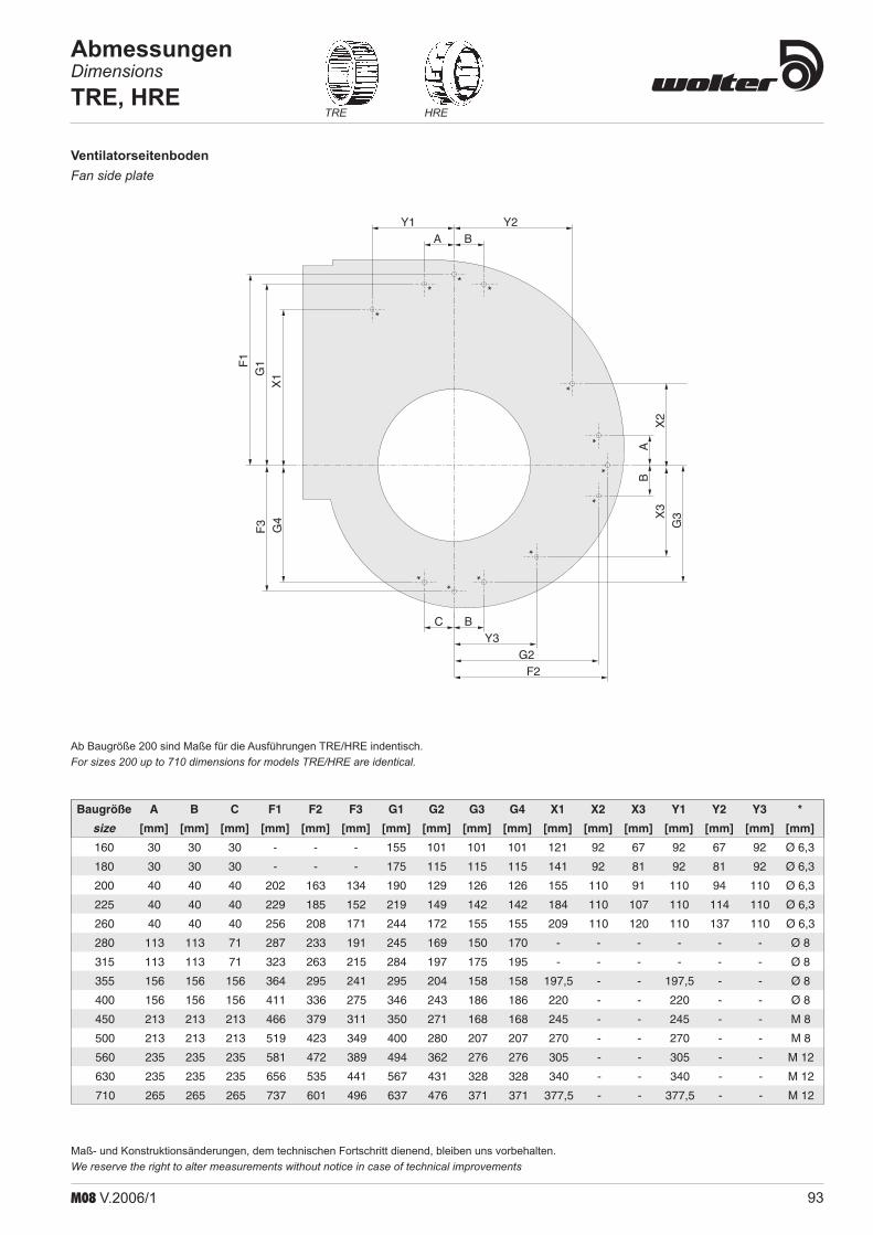
93M08 V.2006/1
HRETRE
Maß- und Konstruktionsänderungen, dem technischen Fortschritt dienend, bleiben uns vorbehalten.We reserve the right to alter measurements without notice in case of technical improvements
AbmessungenDimensionsTRE, HRE
VentilatorseitenbodenFan side plate
Baugröße A B C F1 F2 F3 G1 G2 G3 G4 X1 X2 X3 Y1 Y2 Y3 *
size [mm] [mm] [mm] [mm] [mm] [mm] [mm] [mm] [mm] [mm] [mm] [mm] [mm] [mm] [mm] [mm] [mm]
160 30 30 30 - - - 155 101 101 101 121 92 67 92 67 92 Ø 6,3
180 30 30 30 - - - 175 115 115 115 141 92 81 92 81 92 Ø 6,3
200 40 40 40 202 163 134 190 129 126 126 155 110 91 110 94 110 Ø 6,3
225 40 40 40 229 185 152 219 149 142 142 184 110 107 110 114 110 Ø 6,3
260 40 40 40 256 208 171 244 172 155 155 209 110 120 110 137 110 Ø 6,3
280 113 113 71 287 233 191 245 169 150 170 - - - - - - Ø 8
315 113 113 71 323 263 215 284 197 175 195 - - - - - - Ø 8
355 156 156 156 364 295 241 295 204 158 158 197,5 - - 197,5 - - Ø 8
400 156 156 156 411 336 275 346 243 186 186 220 - - 220 - - Ø 8
450 213 213 213 466 379 311 350 271 168 168 245 - - 245 - - M 8
500 213 213 213 519 423 349 400 280 207 207 270 - - 270 - - M 8
560 235 235 235 581 472 389 494 362 276 276 305 - - 305 - - M 12
630 235 235 235 656 535 441 567 431 328 328 340 - - 340 - - M 12
710 265 265 265 737 601 496 637 476 371 371 377,5 - - 377,5 - - M 12
Ab Baugröße 200 sind Maße für die Ausführungen TRE/HRE indentisch.For sizes 200 up to 710 dimensions for models TRE/HRE are identical .
*
**
*
**
*
**
*
**
C BY3
G2F2
A BY1 Y2
F1
G1
X1
F3 G4
AB
X3
X2
G3

94 M08 V.2006/1
HRETRE
Maß- und Konstruktionsänderungen, dem technischen Fortschritt dienend, bleiben uns vorbehalten.We reserve the right to alter measurements without notice in case of technical improvements .
AbmessungenDimensionsTRE, HRE
AbmessungenDimensionsTREB, HREB
J
A
H
E
M
N O
B
C
a1 zxa2 a1
d2
G
LK
I
S
DIN 6885 T1
d
T
U
10
Baugröße A B C E G H I J K L M N O S T U a1 d zxa2 d2size [mm] [mm] [mm] [mm] [mm] [mm] [mm] [mm] [mm] [mm] [mm] [mm] [mm] [mm] [mm] [mm] [mm] [mm] [mm] [mm]315 640 584 565 315 400 200 821 216 350 445 584 200 344 50 8 28 20 25h6 3x200 10,5355 695 664 623 347 450 224 899 302 393 480 676 230 406 50 8 33 20 30h6 3x216 10,5400 722 760 693 388 500 250 952 302 441 485 731 256 435 50 8 33 20 30h6 4x170 10,5450 868 850 768 432 560 280 1126 401 495 605 793 288 465 60 10 38 20 35h6 5x165 10,5500 893 950 842 476 630 315 1176 426 548 605 863 323 495 60 10 38 22,5 35h6 5x169 13560 1103 964 965 525 710 355 1409 470 613 770 903 363 495 80 12 43 37,5 40h6 5x205 13630 1253 1044 1041 588 800 400 1600 470 689 885 960 408 507 80 12 43 22,5 40h6 5x241 13
TREB 315-630 / 0°HREB 315-630 / 0°
d=18mm
AG 55020
580
20
20225
225
F
B
20
D EC
20
20
= =
100
H
LK R
N
O
M
I
P
S
DIN 6885 T1
d
T
U
10
Baugröße A B C D E F G H I K L M N O P Rsize [mm] [mm] [mm] [mm] [mm] [mm] [mm] [mm] [mm] [mm] [mm] [mm] [mm] [mm] [mm] [mm]710 1800 1084 1307 339 630 534 500 1407 314 792 1025 739 1084 1174 900 450800 2000 1134 1469 380 710 584 597 1569 361 889 1128 818 1134 1224 1000 500900 2200 1194 1651 426 800 644 705 1751 409 997 1220 907 1194 1284 1120 560
1000 2370 1264 1812 456 900 714 801 1912 440 1091 1294 986 1264 1354 1250 630
TREB 710-1000 / 0°HREB 710-1000 / 0°
RD 0 LG 0
Grundrahmen und Motorschlitten gehören zum Lieferumfang.Basic frame and motor slide are included in the fan unit .
RD 0 LG 0

95M08 V.2006/1
HRETRE
Maß- und Konstruktionsänderungen, dem technischen Fortschritt dienend, bleiben uns vorbehalten.We reserve the right to alter measurements without notice in case of technical improvements
AbmessungenDimensionsTRE, HRE
AbmessungenDimensionsTREB, HREB
A
K L H
G
E
M
N O
B
C
I
a1 a1
d2J S
DIN 6885 T1
d
T
U
10
z x a2
Baugröße A B C E G H I J K L M N O S T U a1 d zxa2 d2size [mm] [mm] [mm] [mm] [mm] [mm] [mm] [mm] [mm] [mm] [mm] [mm] [mm] [mm] [mm] [mm] [mm] [mm] [mm] [mm]315 640 584 684 315 400 200 456 216 251 445 584 200 344 50 8 28 20 25h6 3x200 10,5355 695 664 760 347 450 224 507 302 276 480 676 230 406 50 8 33 20 30h6 3x216 10,5400 722 760 848 388 500 250 570 302 306 485 731 256 435 50 8 33 20 30h6 4x170 10,5450 868 850 946 432 560 280 638 401 337 605 793 288 465 60 10 38 20 35h6 5x165 10,5500 893 950 1043 476 630 315 700 426 367 605 863 323 495 60 10 38 22,5 35h6 5x169 13560 1103 964 1157 525 710 355 774 470 409 770 903 363 495 80 12 43 37,5 40h6 5x205 13630 1253 1044 1295 588 800 400 867 470 453 885 960 408 507 80 12 43 22,5 40h6 5x241 13
TREB 315-630 / 90°HREB 315-630 / 90°
AG 550
B
F
20D E E
C
20
225
225
20
20 580
20
20
d=18mm
100
I
H
LK R
S
DIN 6885 T1
d
T
U
10
M
P
NO
TREB 710-1000 / 90°HREB 710-1000 / 90°
Baugröße A B C D E F G H I K L M N O P Rsize [mm] [mm] [mm] [mm] [mm] [mm] [mm] [mm] [mm] [mm] [mm] [mm] [mm] [mm] [mm] [mm]710 1545 1084 1052 211 315 534 138 1424 846 503 1132 632 1084 1174 900 450800 1703 1134 1172 231 355 584 179 1586 958 562 1249 697 1134 1224 1000 500900 1860 1194 1309 255 400 644 227 1768 1080 627 1358 771 1194 1284 1120 560
1000 2000 1264 1442 271 450 714 291 1927 1176 679 1444 836 1264 1354 1250 630
Grundrahmen und Motorschlitten gehören zum Lieferumfang.Basic frame and motor slide are included in the fan unit .
RD 90 LG 90
RD 90 LG 90

96 M08 V.2006/1
HRETRE
Maß- und Konstruktionsänderungen, dem technischen Fortschritt dienend, bleiben uns vorbehalten.We reserve the right to alter measurements without notice in case of technical improvements .
AbmessungenDimensionsTRE, HRE
AbmessungenDimensionsTREB, HREB
H
G
E
M
N O
B
J
Aa1 zxa2 a1
d2
I
C
LK
S
DIN 6885 T1
d
T
U
10
Baugröße A B C E G H I J K L M N O S T U a1 d zxa2 d2size [mm] [mm] [mm] [mm] [mm] [mm] [mm] [mm] [mm] [mm] [mm] [mm] [mm] [mm] [mm] [mm] [mm] [mm] [mm] [mm]315 640 584 614 375 400 200 228 280 251 445 584 200 344 50 8 28 20 25h6 3x200 10,5355 695 664 683 415 450 224 253 355 276 480 676 230 406 50 8 33 20 30h6 3x216 10,5400 722 760 768 466 500 250 278 355 306 485 731 256 435 50 8 33 20 30h6 4x170 10,5450 868 850 863 525 560 280 308 450 337 605 793 288 465 60 10 38 20 35h6 5x165 10,5500 893 950 949 575 630 315 343 450 367 605 863 323 495 60 10 38 22,5 35h6 5x169 13560 1103 964 1057 639 710 355 383 560 409 770 903 363 495 80 12 43 37,5 40h6 5x205 13630 1253 1044 1182 712 800 400 428 560 453 885 960 408 507 80 12 43 22,5 40h6 5x241 13
TREB 315-630 / 270°HREB 315-630 / 270°
M
P
N
OA100
R
I
H
LK
I
S
DIN 6885 T1
d
T
U
10
A
G 550
B
F
20D E E
C
20
225
225
20
20 580
20
20
d=18mm
Baugröße A B C D E F G H I K L M N O P Rsize [mm] [mm] [mm] [mm] [mm] [mm] [mm] [mm] [mm] [mm] [mm] [mm] [mm] [mm] [mm] [mm]710 1545 1084 1052 211 315 534 138 1407 461 503 1132 875 1084 1174 900 450800 1703 1134 1172 231 355 584 179 1569 511 562 1249 972 1134 1224 1000 500900 1860 1194 1309 255 400 644 227 1751 571 627 1358 1080 1194 1284 1120 560
1000 2000 1264 1442 271 450 714 291 1912 636 679 1444 1176 1264 1354 1250 630
TREB 710-1000 / 270°HREB 710-1000 / 270°
RD 270 LG 270
Grundrahmen und Motorschlitten gehören zum Lieferumfang.Basic frame and motor slide are included in the fan unit .Cadre de base et glissière de moteur sont compris .
RD 270 LG 270

97M08 V.2006/1
HRETRE
Maß- und Konstruktionsänderungen, dem technischen Fortschritt dienend, bleiben uns vorbehalten.We reserve the right to alter measurements without notice in case of technical improvements
AbmessungenDimensionsTRE, HRE
30 130BB2
A A2
efx
125A1
e1 f1x125B1
d10x15mm
30 130
da di
zxd
dl
d
Baugröße A A1 A2 B B1 B2 e e1 fx125 f1x125size [mm] [mm] [mm] [mm] [mm] [mm] [mm] [mm] [mm] [mm]160 200 226 256 100 126 156 113 - - -180 224 250 280 112 138 168 125 - - -200 250 276 306 125 151 181 138 75,5 - -225 280 306 336 140 166 196 153 83 - -250 315 341 371 160 186 216 108 93 1 -280 355 381 411 180 206 236 128 103 1 -315 400 426 456 200 226 256 150,5 113 1 -355 450 476 506 224 250 280 50,5 125 3 -400 500 526 556 250 276 306 75,5 138 3 -450 560 586 616 280 306 336 105,5 153 3 -500 630 656 686 315 3410 371 140,5 108 3 1560 710 736 766 355 381 411 55,5 128 5 1630 800 826 856 400 426 456 100,5 150,5 5 1710 900 926 956 450 476 506 450,5 50,5 5 3800 1000 1026 1056 500 526 556 75,5 105,5 7 3900 1120 1164 1176 560 586 616 135,5 105,5 7 3
1000 1250 1276 1306 630 656 686 75,5 138 9 3
Baugröße da dl di d zxdsize [mm] [mm] [mm] [mm] [mm]160 193 183 164 7 6x7180 215 202 183 7 6x7200 255 234 205 7 6x7225 279 259 229 7 6x7250 306 286 256 7 6x7280 348 320 288 10 8x10315 382 356 320 10 8x10355 421 395 361 10 8x10400 464 438 404 10 12x10450 513 487 453 10 12x10500 567 541 507 10 12x10560 639 605 569 12 16x12630 708 674 638 12 16x12710 785 751 715 14 16x14800 875 837 801 14 24x14900 975 934 898 14 24x14
1000 1080 1043 1007 14 24x14
Elastische Stutzen saugseitig (ASS, ASF)Flexible connection inletConnection flexible de côté d’entrée
Elastische Stutzen druckseitig (ABS, ABF)Flexible connection outletConnection flexible de côté de sortie

98 M08 V.2006/1
HRETRE
Maß- und Konstruktionsänderungen, dem technischen Fortschritt dienend, bleiben uns vorbehalten.We reserve the right to alter measurements without notice in case of technical improvements .
AbmessungenDimensionsTRE, HRE
d1l1
ht
Ø D
d2
FederschwingungsdämpferSpring isolators
GummischwingungsdämpferRubber isolators
Type Nennbereich type range type [N] - SN 5 115 - 285 FSD 2 SN 6 175 - 435 FSD 3 SN 7 285 - 650 FSD 4 SD 4 475 - 1200 FSD 5 SD 5 720 - 1700 FSD 6 SD 6 1130 - 2700 FSD 7 SD 7 1815 - 3800
Type d1 d2 D h l1 t type [mm] [mm] [mm] [mm] [mm] [mm] G 15 M 6 M 6 25 15 18,5 6 G 30/1+2 M 8 M 8 40 30 24,5 7 G 30/3-5 M 10 M 10 50 30 34 8,8 G 40/1+2 M 16 M 16 100 40 43 17,5 G 55/1+2 M 12 M 12 75 55 37 11,5
Schwingungdämpfer nur auf Druck und nicht auf Zug belasten!Use vibration dampers only with compression and never use with traction charge!
M 10
1195
120150
129461
Ø 44Ø 70
für SN - Typenfür SD - Typen
(Höhe ohneLast für
SN - Typen) (Höhe ohneLast für
SD - Typen)
99M08 V.2006/1
BescheinigungenCertificats
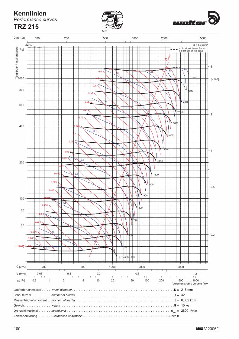
100 M08 V.2006/1
Laufraddruchmesser . . . . . wheel diameter . . . . . . . . . . . . . . . . . . . . . . . . . . . . . . . . . . . . . . . . . . . . . . . . . . . . . . . . . . . . .D =
Schaufelzahl . . . . . . . . . . . number of blades . . . . . . . . . . . . . . . . . . . . . . . . . . . . . . . . . . . . . . . . . . . . . . . . . . . . . . . . . . . z =
Massenträgheitsmoment . moment of inertia . . . . . . . . . . . . . . . . . . . . . . . . . . . . . . . . . . . . . . . . . . . . . . . . . . . . . . . . . . . J =
Gewicht . . . . . . . . . . . . . . . weight . . . . . . . . . . . . . . . . . . . . . . . . . . . . . . . . . . . . . . . . . . . . . . . . . . . . . . . . . . . . . . . . . . .G =
Drehzahl maximal . . . . . . . speed limit . . . . . . . . . . . . . . . . . . . . . . . . . . . . . . . . . . . . . . . . . . . . . . . . . . . . . . . . . . . . . . nmax =
Zeichenerklärung . . . . . . . Explanation of symbols . . . . . . . . . . . . . . . . . . . . . . . . . . . . . . . . . . . . . . . . . . . . . . . . . . . Seite 8
TRZ
1 10 100 10002 5 20 50 200 5000.5pd2 [Pa]
100 1000200 500 2000 5000·V [C.F.M.]
0.1 10.2 0.5 20.05·V [m³/s]
1000 2000 5000500200·V [m³/h]
1
2
5
0.5
0.2
[in.WG]
100
1000
200
400
600
800
80
60
40
[Pa]
n [1/min]= 500
560
630
710
800
900
1000
1120
1250
1400
1600
1800
2000
2250
2500
2800
Lw [dB(A)]= 45
48
51
54
57
60
63
66
69
72
75
78
81 8487 90
P [kW]= 0,004
0,005
0,006
0,008
0,01
0,013
0,016
0,02
0,025
0,032
0,04
0,05
0,06
0,08
0,1
0,125
0,16
0,2
0,25
0,32
0,4
0,5
0,60,8 1 1,25 1,6 2 2,5
η max
Volumenstrom / volume flow
Totaldruck
/totalpressure 160230 TRZ 05 215
totnicht einsetzbarer Bereichdo not use in this area
p = 1,2 kg/m³
KennlinienPerformance curvesTRZ 215
215 mm420,062 kgm²10 kg2800 1/min

101M08 V.2006/1
HRZTRZ HRZP
Maß- und Konstruktionsänderungen, dem technischen Fortschritt dienend, bleiben uns vorbehalten.We reserve the right to alter measurements without notice in case of technical improvements
160
291
30
9 x 15
83305140
295326
351484
164
134
195
220
305
2 x
10019
432
5
6
Ø20h6
125
60
2 x 100
2800/min
2600/min
2400/min
2200/min
2000/min
1700/min
1000/min
3000/min
Volumenstrom/ air flow V [m³/h]·
stat
isch
e D
ruck
erhö
hung
/p
[Pa]
stat
ic p
ress
ure
Dst
at
0 1000 2000 3000 4000 5000
0
100
200
300
400
500
600
700
800
900
1000
1100
1200
Ventilator TRZ 215
25030
0
Einbaubreite B nach Kundenwunsch
H=
310
295
164
351
a
Einbaueinheit TRZD 215Unit TRZD 215 Kennlinie der Einbaueinheit TRZD 215 in Abluftgerät AGF800
Performance curve of TRZD 215 mounted in extract unit AGF800
nicht im grauen Bereich einsetzendot not use within the grey area
Motor Leistung Drehzahl a B x H min.
Motor Power Speed [mm] [mm]
B3 80-2 1,1 2850 min-1 570 630 x 310
B3 90S-2 1,5 2850 min-1 600 760 x 310
AbmessungenDimensionsTRZ 215

102 M08 V.2006/1
Pressure (all) ≈ (rotational speed)2
•
Power absorbed ≈ (rotational speed)3
•
Size change - constant speed (for geometrically similar fans only)
Pressure ≈ (impeller Diameter)2•
Power absorbed ≈ (impeller Di-ameter)5
•
Density change - constant speed - constant size
Pressure ≈ Density•
Power absorbed ≈ Density•
PressureDynamic Pressure [Pa]•
whereby: ρ = air density in [kg/m³]v = air velocity in [m/s]
Speed change - constant size
Volume flow ≈ rotational speed• Volume flow ≈ (impeller Diame-ter)3
•
Volume flow no change•
Total pressure•
Absorbed power - calculation in duty point
Fan Laws - Proportional Laws
Here are some usefull informations and fan laws:Nachstehend finden Sie einige nützliche Hinweise und Gesetzmäßigkeiten beim Umgang mit Ventilatoren:
die Drücke ändern sich mit der 2. Potenz zum Drehzahlverhältnis
•
der Kraftbedarf ändert sich in der 3. Potenz zum Drehzahlverhältnis
•
Veränderter Ventilatordurch-messer (nur für geometrisch ähnliche Ventilatoren) bei gleichbleibender Drehzahl
die Pressung ändert sich in der 2. Potenz zum Durchmesserver-hältnis
•
der Kraftbedarf ändert sich in der 5. Potenz zum Durchmesserver-hältnis
•
Veränderung der Luftdichte bei unveränderter Drehzahl und gleichem Durchmesser
der Kraftbedarf ändert sich pro-portional zur veränderten Luft-dichte
•
Druckdynamische Druck [Pa]•
wobei: ρ = Luftdichte in [kg/m³]v = Luftgeschwindigkeit im Venti-
lator in [m/s]
Veränderte Drehzahl bei glei-chem Ventilatordurchmesser
die Pressung ändert sich proportio-nal zur veränderten Luftdichte
•
Volumenstrom ändert sich in der 3. Potenz zum Durchmesserver-hältnis
•Der Volumenstrom ändert sich pro-portional zum Drehzahlverhältnis
•
Volumenstrom bleibt gleich•
Gesamtdruck•
Errechnung des Kraftbedarfs an der Welle:
Strömungstechnische Gesetzte für Ventilatoren
V2 · ___ V1
·
= n2 ___
n1
Dp1 ___
Dp2
= (
n1 ___
n2
)² = (
V1 · ___ V2
·
)²
P1 ___
P2
= (
n1 ___
n2
)3 = (
V1 · ___ V2
·
)3
pd
=
ρ __ 2
· v2
Dp1 ___
Dp2
=
ρ1 ___
ρ2
=
T2 ___
T1
V2 · ___ V1
·
= (
D2 ___
D1
)3
P1 ___
P2
= (
D1 ___
D2
)5
Dp1 ___
Dp2
= (
D1 ___
D2
)2
P1 ___
P2
=
ρ1 ___
ρ2
=
T2 ___
T1
V · = constant
pt
= pst + pd
PL [kW]= V · [m³/s] · Dpt [Pa] ______________
A2·1000
Technische InformationenTechnical Informations

103M08 V.2006/1
1. Characteristic Fan Curve This is the characteristic curve, which is determined on a test bed experimentally for every type of fan. This shows that the fan can in principle only operate on its characteristic curve, i.e. the operating point of a fan always lies on its characteristic curve.
pt
V.
2. Characteristic Curve of the Plant (Resistance Parabola) Each plant has its own characteristic curve (resistance parabola), which by advance calculation can be determined more or less exact, so that the path of the characteristic curve can be drawn with sufficient accuracy.
pt
V.
3. Coordination between Fan and Plant The operating point of the fan always lies at the intersection of characteristic fan curve and characteristic plant curve (resistance parabola). From this results the actually moved volume flow, and the actual pressure difference to be overcome by the fan; among others the characteristic fan curve V (n = const.) is given, also the char-acteristic plant curve 1, so that the operating point B1 with V
.1 and pt1 results.
Figure a) shows the conditions for a centrifugal fan wheel with backward curved blading and figure b) the conditions for a centrifugal fan wheel with forward curved blading. If the volume flow is to be throttled by DV
. to V
.2 without
reducing the fan Speed, it is generally customary to fit an additional resistance in form of a throttle valve, orifice or similar into the plant.Figs. a) and b) show that a pressure loss of the size Dpst must be fitted into the plant in order to reduce the volume flow to V
.2 . The resistance parabola 1
of the plant thus changes into 2 so that the operating point B2 follows. This shows that a fan with forward curved blading can be throttled more economically as one with back- ward curved blading. A throttling of the fan speed is to prefer to any other method for sound rea-sons.
PL [kW]= V · [m³/s] · Dpt [Pa] ______________
A2·1000
a) b)
pt
pt2
pt1
p’
st
V.
V.
2 V.
1
V.
B1
B2
1
V
2
pt
p’
st
V.
V.
2 V.
1
V.
pt2
B2
pt1B1
1
2
V
Zusammenspiel Ventilator/AnlageCoordination fan plant
1. Ventilatorkennlinie Sie ist die Kennlinie, welche auf einem Prüfstand für jeden Venti-latortyp experimentell ermittelt wird. Daraus ergibt sich, dass der Ventilator grundsätzlich nur auf seiner Kennlinie arbeiten kann, d. h. der Betriebspunkt eines Ventilators liegt immer auf seiner Kennlinie.
2. Anlagenkennlinie (Widerstandsparabel) Jeder Anlage ist ihre eigene Kennlinie zugeordnet (Widerstand-sparabel) und Iäßt sich durch Vorausberechnungen mehr oder weniger genau bestimmen, so dass der Verlauf der Kennlinie mit genügender Genauigkeit gekennzeichnet werden kann.
3 Zusammenspiel von Ventilator und AnlageDer Betriebspunkt des Ventilators ist immer der Schnittpunkt zwischen Ventila-torkennlinie und Anlagenkennlinie (Widerstandsparabel). Dadurch ergibt sich der tatsächlich geförderte Volumenstrom und die tatsächlich vom Ventilator zu überwindende Druckdifferenz; z. B. sei gegeben die Ventilatorkennlinie V (n = const.), die Anlagenkennlinie 1, so daß sich der Betriebspunkt B1 mit V
.1 und pt1 ergibt.
Abbildung a) zeigt die Verhältnisse bei einem Radialrad mit rückwärts- gekrüm-mter Beschaufelung und Abbildung b) die Verhältnisse bei einem Radiallaufrad mit vorwärtsgekrümmter Beschaufelung. Soll nun der Volumenstrom um DV
. auf V
.2 gedrosselt werden, ohne dabei die
Ventilatordrehzahl zu reduzieren, so wird meist in die Anlage ein zusätzlicher Widerstand in Form einer Drosselklappe, Blende oder ähnliches eingebaut.Aus den Abbildungen a) und b) Iäßt sich entnehmen, dass in der Anlage ein Druckverlust in der Größe Dpst eingebaut werden muss, um den Volumenstrom auf V
.2 zu verringern. Die Widerstandsparabel 1 der Anlage ändert sich somit
in 2, so dass sich der Betriebspunkt B2 ergibt. Daraus Iäßt sich entnehmen, dass ein Ventilator mit vorwärtsgekrümmter Beschaufelung wirtschaftlicher zu drosseln ist als ein solcher mit rückwärts-gekrümmter Beschaufelung. Eine Drosselung über die Ventilatordrehzahl ist aus geräuschlichen Gründen jeder anderen Methode vorzuziehen.

104 M08 V.2006/1
These fans are produced on modern machines and equipment. The rotors (impellers with shaft) are carefully balanced. Each fan is controlled and tested before it leaves the factory.
Before operating the fan, please check the following thingsCheck for transportation damagesIs the fan deformed? (Bulges, casing warped)Does the impeller rotate without noise from the bearings, and without touch-ing the inlet ring?
Check for foreign substances Are there any foreign substances in the impeller or in the casing? If affirmative, it must be removed (i. e. packing material in the TRZ wheel).
Check for corrosion damagesThe fans are supplied in very good galvanized finish. If stored for a longer period under humid and aggressive ambient conditions, zinc oxidizes. This has to be removed immediately (also inside the fan).
Assembly and mounting The fan has to be mounted on the base or vibration dampers, with feet, square frame or base frame, in a way that it is not warped. The shaft has to be horizontal. Turn rotor (impeller with shaft) by hand. In case the impeller touches the inlet ring, loosen the inlet ring and refix it in a way that there is a uniform gap be-tween inlet ring and impeller (Especially important for the type HRZ 1 HRE). The fans are normally driven by a narrow belt drive. The instructions of the manufacturer of the belt drive have to be respected. The bearings are temperature resistant from -30 degree C up to +85 degree C. Depending on the location and way, how the fan is installed, different kinds of protection guards or devices could be necessary. DIN instructions or other instructions of local authorities or unions have to be respected. The speed nmax indicated on the type plate may not be exceeded!
Operation Switch on the fan for a short moment to check whether the direction of rotation is correct (See arrows at the fan casing).If incorrect, change the direction of rotation by changing the wiring. (Respect the instructions of power supply companies).
Maintenance The fans are maintenance free, only a control regarding contamination (fat, dust, etc.) has to be carried out.The bearings are sealed for life with lithium base grease, suitable for approx. 20.000 operating hours. If the fan is operated more than 20.000 hours, or in case the bearings are damaged, they have to be exchanged (if bearings with rubber sealing, also this sealing has to be exchanged - a bearing chart is attached). The bearings are equipped with a locking ring. To remove the bearing, this locking ring has to be loosened and the casing of the bearing has to be opened - then the bearing can be taken off from the cleaned and degreased shaft.Important for a constantly good performance of the fan is a clean impeller. Especially TRZ / TRE impellers have to be cleaned regularly, in case they are operated in air which is contaminated by oil, grease and colour pigments.
Belt tension Regular control of belt tension is very important. In any case, the belt tension has to be controlled after the first 100 operating hours, and then every 1000 operating hours or at least once a year. The belt tension is controlled by “press-ing the belt with the fingers” (See drawing 1). A good tension is achieved by a total bending of approx. 2-3 cm. Used belts have to be replaced by belts of the same type. Control at the same time the fixation of the belt disc at the axis and the alignment of the belt. (See drawing 2)
(Drawing 1) Belt tension bending of approx. 2-3 cm.
(Drawing 2) alignment of the belt disc.
Die Fertigung der Wolter Ventilatoren erfolgt mit modernsten Maschinen und Vorrichtungen. Die Rotoren (Schaufelrad mit Welle) werden sorgfältig ausgewuchtet. Jeder Ventilator durchläuft im Werk eine sorgfältige Endkon-trolle.
Bevor der Ventilator betrieben wird, müssen nach-folgende Punkte beachtet werden: Kontrolle auf Transportschäden Ist der Ventilator deformiert? (Beulen, Gehäuse verzogen) Lässt sich der Rotor ohne Lagergeräusche oder Schleifen des Schaufelrades an der Einströmdüse drehen?
Kontrolle auf FremdkörperÜberprüfen, ob im Schaufelrad oder im Gehäuse Fremdkörper vorhanden sind. Diese sind unbedingt zu entfernen. (z.B. Verpackungsfülle im TRZ-Schaufelrad).
Kontrolle auf Korrosionsschäden Wolter Ventilatoren werden in sehr guter verzinkter Ausführung geliefert. Durch längere Lagerung in feuchter und aggressiver Umgebung kann “Weißrost” entstehen. Dieser muss (auch im Ventilatorinnenraum) sofort entfernt werden.
Auf - und Einbau Ventilator mit Füßen, Rechteckrahmen oder Grundrahmen auf dem Unterbau oder den Schwingungsdämpfern so festschrauben, dass der Ventilator nicht verspannt wird. Die Welle muss horizontal liegen. Rotor (Welle mit Schaufelrad) von Hand drehen. Wenn das Schaufelrad an der Düse schleift, die Düse am Gehäus-eseitenboden lösen und so versetzen, dass ein gleichmäßiger Spalt zwischen Düse und Rad entsteht. (Besonders wichtig bei Typ HRZ / HRE). Der Antrieb erfolgt in der Regel über einen Schmalkeilriemenantrieb. Die Richtlinien des Riemenherstellers sind zu beachten. Die Lager sind für einen Temperaturbereich von -30°C bis +85°C ausgelegt. Je nach Aufstellungsort und -art können unterschiedliche Schutzvorrich-tungen erforderlich werden. Hier sind die Vorschriften nach DIN oder den entsprechenden Berufsgenossenschaften einzuhalten.Die auf dem Typenschild angegebene Drehzahl nmax darf nicht überschrit-ten werden!
Inbetriebnahme Ventilator nur ganz kurz einschalten und kontrollieren, ob Drehrichtung stimmt. (Drehrichtungspfeile am Gehäuseseitenboden) Gegebenenfalls die Drehrichtung durch Kabelumklemmung verändern. (Vor-schriften von EVU und EVZ beachten).
Wartung Wenn man von einer Kontrolle auf Verunreinigung (Fett. Staub u.ä.) einmal absieht, sind die Ventilatoren wartungsfrei. Die Lager haben eine Lebensdauerschmierung mit Lithiumseifenfett auf 20.000 Betriebsstunden. Bei Überschreitung dieser Betriebsstundenzahl oder bei Lagerschäden müssen die Lager ausgetauscht werden (bei Lagern mit Gummiring auch der Gummiring). Die Lager sind mit Spannringen versehen. Nach Lösen des Spannrings und 0ffnen der Lagerspeichen oder des Lagergehäuses kann das Lager über die (gesäuberte und entfettete) Welle abgezogen werden. Wichtig für eine gleichmäßig hohe Leistung des Ventilators ist ein sauberes Schaufelrad. Vor allem sind TRZ / TRE - Schaufelräder, bei öligen und mit Farbenteilen verunreinigten Fördermedien, zu reinigen.
KeilriemenspannungRegelmäßige Kontrolle der Keilriemenspannung ist die erste Voraussetzung. In jedem Fall muss die Keilriemenspannung nach den ersten 100 Drehstunden und danach alle 1000 Drehstunden oder aber minimal 1 Mal pro Jahr kontrol-liert werden. Die Keilriemenspannung wird mit einem “Fingerdruck” kontrolliert (siehe Abb 1). Die korrekte Spannung ergibt eine totale Durchbiegung von ungefähr 2 bis 3 cm.Abgenutzte Keilriemen müssen durch denselben Typ Keilriemen ausgewech-selt werden. Kontrollieren Sie gleichzeitig auch, ob die Keilriemenscheiben gut auf ihrer Achse befestigt sind und auf einer Ebene fluchten (siehe Abb. 2).
Betriebs- und Wartungsanleitung TRZ / TRE und HRZ / HREOperating and maintenance instructions TRZ / TRE and HRZ / HRE
(Abb. 1) Keilriemenspannung - Durchbeugung 2 bis 3 cm.
(Abb. 2) Riemenscheiben auf gleicher Höhe.

105M08 V.2006/1
Größe Symbol Benennung Designation Einheit
Unit
A Querschnittsfläche Cross-section m²
c Strömungsgeschwindigkeit Flow speed m/s
C400V Betriebskondensator Capacitor µF
D2 Durchmesser des Laufrades Impeller diameter m
d Rohrdurchmesser Pipe diameter m
dg gleichwertiger Durchmesser Equivalent diameter m
g Fallbeschleunigung Gravitational speed acceleration m/s²
IN Nennstrom Rated current A
IA / IN Verhältnis Anlaufstrom zu Nennstrom Ratio of starting current to rated current
D I Stromanstieg bei Teilspannung Current increase in component voltage area %
l Rohr- bzw. Kanallänge Pipe or channel length m
LPA A-bewerteter Schalldruckpegel Sound pressure level A-weighted dB(A)
LWA A-bewerteter Schalleistungspegel Sound power level A-weighted dB(A)
LWA2 Schalleistungspegel zur Umgebung Sound power level to surrounding dB(A)
LWA3 Ansaugkanalschalleistungspegel Inlet sound power level induct dB(A)
LWA4 Ausblaskanalschalleistungspegel Outlet sound power level induct dB(A)
LWA5 Freiansaug-Schalleistungspegel Inlet sound power level unducted dB(A)
LWA6 Freiausblas-Schalleistungspegel Outlet sound power level unducted dB(A)
n Drehzahl Speed 1/min (bzw. 1/s)
P1 Motoraufnahme Leistung motor power consumption kW (bzw. W)
pst (pfa) statischer Druck Static pressure Pa
∆ pst Differenz der statischen Drücke Differential static pressure Pa
D pfa min erforderlicher statischer Mindestgegendruck min. required conter pressure Pa
pd dynamischer Druck Dynamic pressure Pa
pd2 dynamischer Druck am Ventilatoraustritt Dynamic pressure at fan outlet Pa
∆ pd Differenz der statischen Drücke Differential dynamic pressure Pa
pt Gesamtdruck Total pressure Pa
∆ pt Differenz der Gesamtdrücke Difference of total pressures Pa
T Kelvin-Temperatur Temperature in Kelvin K
t Celsius-Temperatur Temperature in Celsius °C
tR max. zulässige Fördertemperatur max. permissable medium temperature °C
u2 Umfangsgeschwindigkeit des Laufrades (außen) Circumferential speed of the impeller (outside) m/s
V .
Volumenstrom Volume flow m³/h (bzw. m³/s)
ρ Dichte des Fördermediums Density of medium kg/m³
η Wirkungsgrad Efficiency -
ϕ Volumenzahl Volume number -
ψ Druckzahl Pressure number -
ζ Widerstandsbeiwert Coefficient of drag -
λR Rohr- bzw. Kanalreibungsbeiwert Coefficient of friction of channel or pipe -
Symbol Bedeutung / Meaning Symbol Bedeutung / Meaning Symbol Bedeutung / Meaning
5-Stufen-Steuergerät, transformatorisch5-step transformer control
DrehzahlumschalterSpeed control switch
SchaltplanWiring diagram
Steuergerät, stufenlos, transformatorischContinuously adjustable transformer control
GeräteausschalterOff-Switch
explosionsgeschütztflame proof
Steuergerät, stufenlos, elektronischContinuously adjustable electronic control
GewichtWeight
AbmessungenDimensions
MotorschutzschalterMotor protection switch
SchutzartProtection class
ZubehörAccessories
Symbole und FormelzeichenSymbols and technical formula symbols

Werk und Hauptverwaltung Malsch
Seit nahezu 30 Jahren entwickelt und fertigt WOLTER Ventilatoren und lüftungstechnische Geräte für den Weltmarkt. Aufgrund dieser langjährigen Erfahrung konnte das umfangreiche Lieferprogramm um zahlreiche Neuentwicklungen in den letzten Jahren erfolgreich erweitert werden.
Auf dem Klima- und Lüftungssektor hat Firma Wolter einen anerkannten Namen und wird auch gerne für besondere Ausführungen in Anspruch genommen.
WOLTER legt höchsten Wert auf innovative Technik und Qualität. Die Erfahrung der bestens ausgebildeten Mitarbeiter steht den Kunden weltweit zur Verfügung und garantiert die schnelle und sorgfältige Erledigung aller Kundenwünsche. Computergestützte Fertigung und Produktüberwachung sichern höchste Präzision in allen Bereichen.
Die beiden Produktionsstätten in Deutschland wurden im Laufe der Jahre um mehrere Montagebetriebe in Fernost erwei-tert. Das Unternehmen verfügt über Labors zur Leistungs- und Materialprüfung, Akustik und Regelungstechnik.
WOLTER-Produkte werden nach dem neuesten Stand der Technik und den weltweit anerkannten Normen, wie AMCA, BS 848, ISO 9001, DIN 24163 und PIARC 1995, gerfertigt und ge-prüft. Sie finden vielfältigen Einsatz: lüftungstechnische Anlagen, Industrie, Bergbau, Tunnelbau, Landwirtschaft, Marine etc. Durch ständige Erweiterung der Produktpalette sichert sich WOLTER eine hervorragende Position im Wettbewerb.
WOLTER-Produkte werden in vielen Länder erfolgreich eingesetzt. Eine gut geplante Vertriebs- und Serviceorganisation garantiert optimale Unterstützung bei Planung, Ausführung und Kundendienst.
Firma WOLTER bemüht sich, mehr als nur Lieferant für alle Kunden zu sein, und versteht sich schon während der Pro-jektierungsphase als kompetenter Partner.
For nearly 30 years WOLTER has developed and produced fans and ventilation equipment for the world market. This long period of experience has enabled WOLTER to successfully enlarge its range of products by numerous new developments over the past years.
In the heating and ventilation market WOLTER is a well established and renown name. More and more the company provides special designs and solutions for its clients.
High priority is given to innovative techniques and quality. Worldwide, WOLTER customers rely on the experience and knowledge of the well-trained staff that guarantees a prompt and careful execution of all demands and orders. Computer-ized production and quality control stand for highest precision in every respect.
Over the years several assembly plants were established in the Far East in addition to the two factories in Germany. Laboratories to test performance, materials, acoustics and speed controlling systems are at the company’s disposal.
WOLTER products are manufactured and checked accord-ing to the latest developments in technology and the worldwide accepted standards like AMCA, BS 848, ISO 9001, DIN 24163 and PIARC 1995. There is a wide range of possibilities to use WOLTER products: heating and ventilation systems, industry, mining, tunnel ventilation, agriculture, navy, offshore business, etc. The permanent improvement of existing products and new developments secure an outstanding position for WOLTER in the global market.
WOLTER products are successfully installed around the world. The company is represented with a well planned sales and service organisation, guaranteeing best support regarding planning, execution and after-sales service.
WOLTER wants to be more than just a supplier, WOLTER will already be a competent partner in the early project phase.

Wolter GmbH+Co KG • Am Wasen 11 • D-76316 Malsch/Germany • Tel. (+49)07204/92010 • Fax (+49)07204/920111http://www.wolterfans.de • e-mail: [email protected] PRINTED IN GERMANY 2006/04