Embed Size (px)
Citation preview
8/18/2019 Centre Pompidou Metz Final Report
http://slidepdf.com/reader/full/centre-pompidou-metz-final-report 1/19
Mikhail Grinwald and Karen Chi Lin
Project Report – Centre Pompidou-Metz (2010)
Shigeru Ban Architects Europe, Jean de Gastines Architectes, SJB Kempter Fitze AG
May, 6 2011
ARCH 3603 : Structural Systems
The Centre Pompidou-Metz was completed in May of 2010, designed by the offices of
Shigeru Ban Architects Europe and Jean de Gastines Architectes, with structural engineering by
SJB Kempter Fitze AG and digital modeling by DesigntoProduction Stuttgart. The center is a
satellite location of the Centre Georges Pompidou Paris (Renzo Piano, Richard Rodgers), a
museum of contemporary art in Metz, Alsace-Lorraine, programmed for three large exhibition
and gallery spaces, auditorium, theatre and a central forum. The programmatic parti of the
project is essential to the more formal aspects of its architecture, which become a structurally
expressive, yet fluid, aesthetic. Architecture and structure are physically and conceptually
indistinguishable. Common in much of the work of Shigeru Ban Architects, a structural module
is rigorously deployed throughout the project. Where its regularity and rigor are met by its
formal ingenuity – the roof canopy surface – structural complexity enables its unique
architecture.
ARCHITECTURAL AND STRUCTURAL INVESTIGATION
ROOF LATTICE STRUCTURE
The specific focus of both the investigation and the model was the primary timber
Glulam roof canopy and the central steel truss spire. Both act interdependently as gravity andlateral superstructure, and meet the approximately 405 foundation piles both directly and
indirectly through a concrete slab. The roof spans an area over 8,500 square meters, and is
developed as a projected grid of tessellated regular hexagons defined as a network of laminated
timber beams of uniform cross-section, 44 by fourteen centimeters and measuring over sixteen
kilometers in total length. Larger support beams travel along five effective spines, regulating the
profile of the surface and measuring sixteen meters in length with an increased structural section
of eighteen by 100 centimeters. These, more structural, members are double-curved timbers of
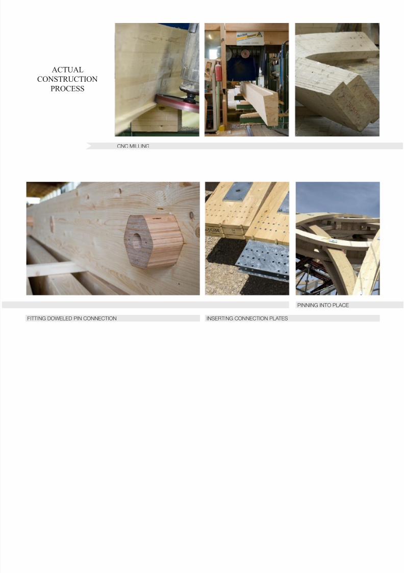
spruce sourced from Austria and Switzerland for premium structural quality. Due to the extreme
complexity of these elements, each was individually manufactured on advanced CNC-mills and
brought in partially prefabricated sections to the site. The structural integrity of the lattice,
however, is in its combination of six independent bearing layers: three sets of two Glulam beams
on each axis of the hexagonal grid and a series of rectangular cross section spacers fastened
8/18/2019 Centre Pompidou Metz Final Report
http://slidepdf.com/reader/full/centre-pompidou-metz-final-report 2/19
Grinwald, Lin 2
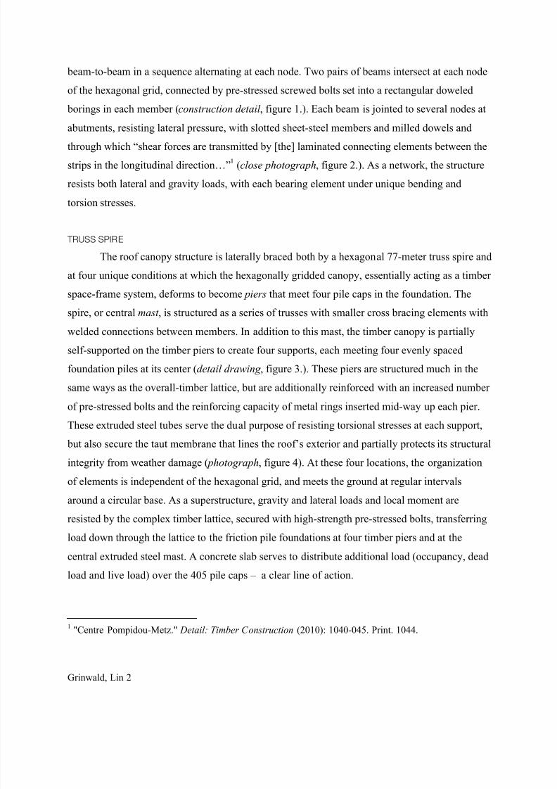
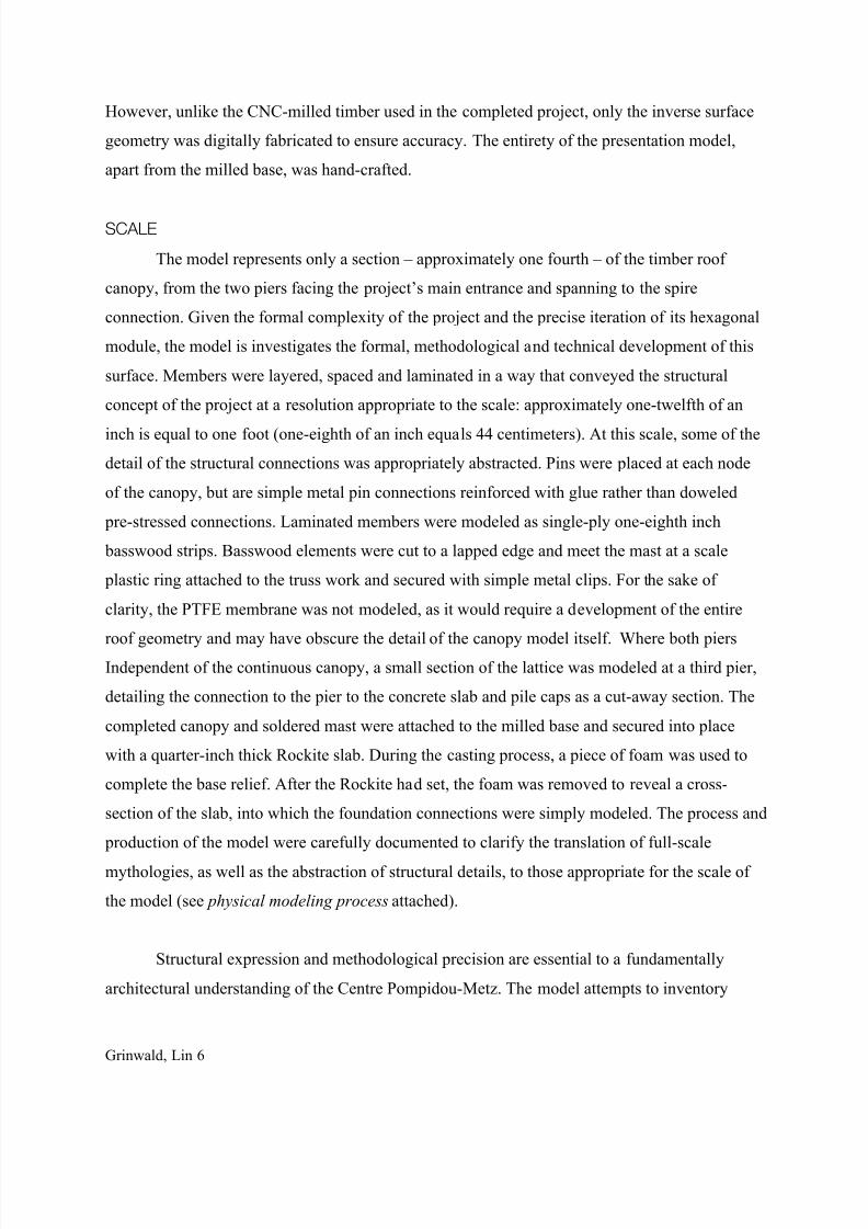
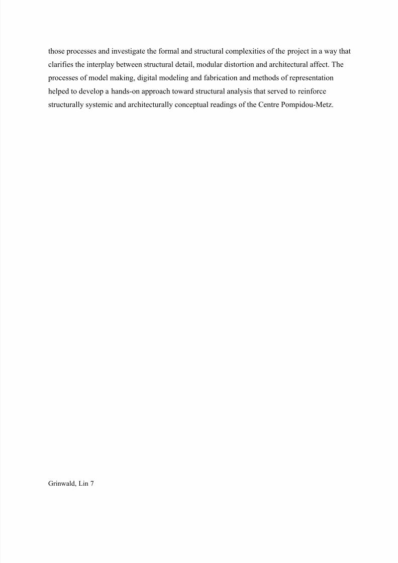
beam-to-beam in a sequence alternating at each node. Two pairs of beams intersect at each node
of the hexagonal grid, connected by pre-stressed screwed bolts set into a rectangular doweled
borings in each member (construction detail , figure 1.). Each beam is jointed to several nodes at
abutments, resisting lateral pressure, with slotted sheet-steel members and milled dowels and
through which “shear forces are transmitted by [the] laminated connecting elements between the
strips in the longitudinal direction…”1 (close photograph, figure 2.). As a network, the structure
resists both lateral and gravity loads, with each bearing element under unique bending and
torsion stresses.
TRUSS SPIRE
The roof canopy structure is laterally braced both by a hexagonal 77-meter truss spire and
at four unique conditions at which the hexagonally gridded canopy, essentially acting as a timber
space-frame system, deforms to become piers that meet four pile caps in the foundation. The
spire, or central mast , is structured as a series of trusses with smaller cross bracing elements with
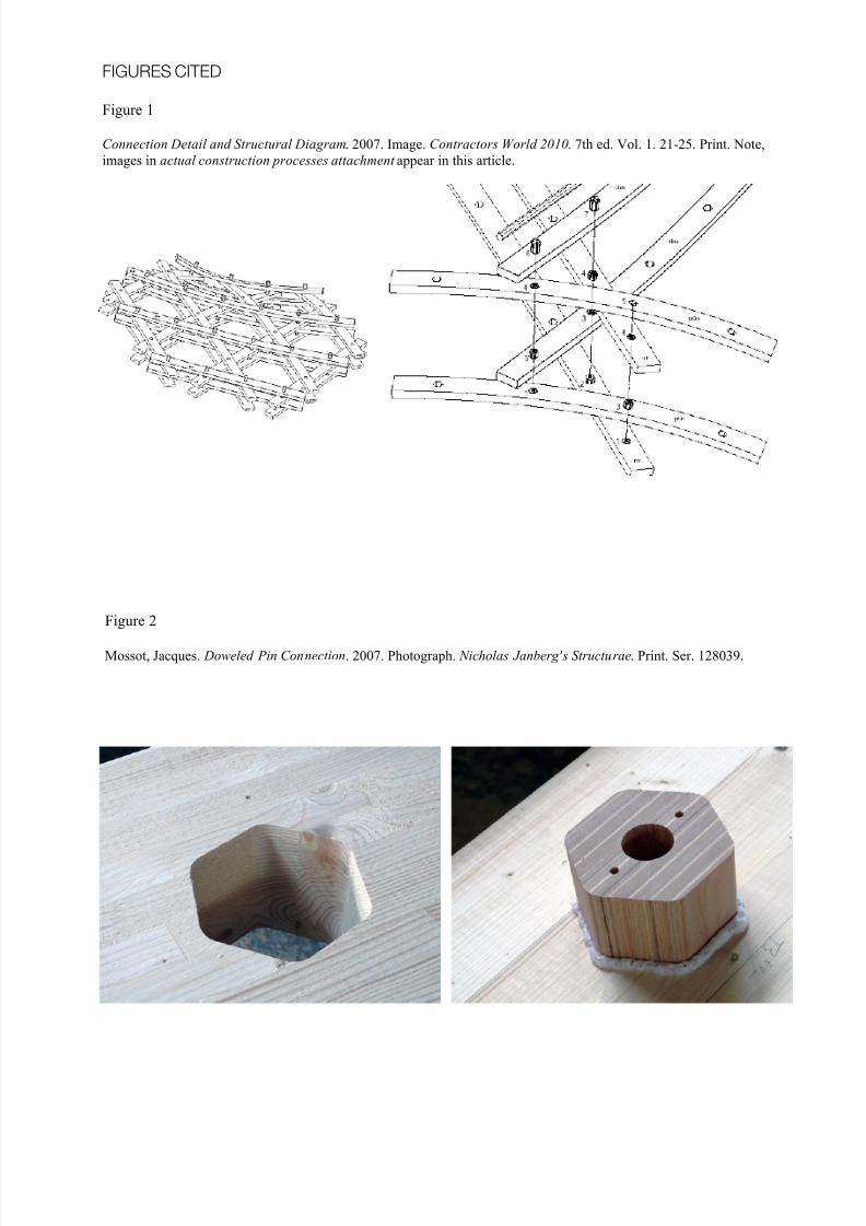
welded connections between members. In addition to this mast, the timber canopy is partially
self-supported on the timber piers to create four supports, each meeting four evenly spaced
foundation piles at its center (detail drawing , figure 3.). These piers are structured much in the
same ways as the overall-timber lattice, but are additionally reinforced with an increased number
of pre-stressed bolts and the reinforcing capacity of metal rings inserted mid-way up each pier.
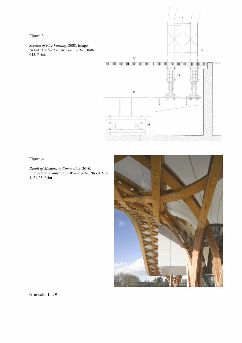
These extruded steel tubes serve the dual purpose of resisting torsional stresses at each support,
but also secure the taut membrane that lines the roof’s exterior and partially protects its structural
integrity from weather damage ( photograph, figure 4). At these four locations, the organization
of elements is independent of the hexagonal grid, and meets the ground at regular intervals
around a circular base. As a superstructure, gravity and lateral loads and local moment are
resisted by the complex timber lattice, secured with high-strength pre-stressed bolts, transferring
load down through the lattice to the friction pile foundations at four timber piers and at the
central extruded steel mast. A concrete slab serves to distribute additional load (occupancy, dead
load and live load) over the 405 pile caps – a clear line of action.
1 "Centre Pompidou-Metz." Detail: Timber Construction (2010): 1040-045. Print. 1044.
8/18/2019 Centre Pompidou Metz Final Report
http://slidepdf.com/reader/full/centre-pompidou-metz-final-report 3/19
Grinwald, Lin 3
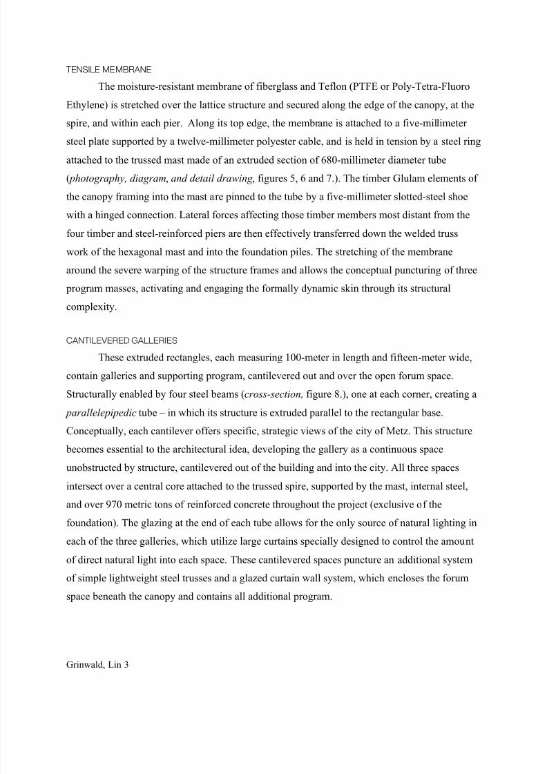
TENSILE MEMBRANE
The moisture-resistant membrane of fiberglass and Teflon (PTFE or Poly-Tetra-Fluoro
Ethylene) is stretched over the lattice structure and secured along the edge of the canopy, at the
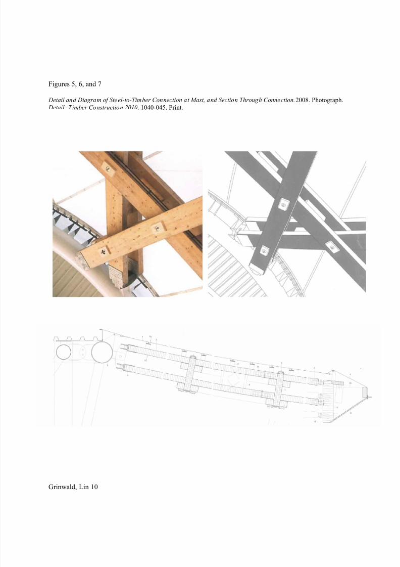
spire, and within each pier. Along its top edge, the membrane is attached to a five-millimeter
steel plate supported by a twelve-millimeter polyester cable, and is held in tension by a steel ring
attached to the trussed mast made of an extruded section of 680-millimeter diameter tube
( photography, diagram, and detail drawing , figures 5, 6 and 7.). The timber Glulam elements of
the canopy framing into the mast are pinned to the tube by a five-millimeter slotted-steel shoe
with a hinged connection. Lateral forces affecting those timber members most distant from the
four timber and steel-reinforced piers are then effectively transferred down the welded truss
work of the hexagonal mast and into the foundation piles. The stretching of the membrane
around the severe warping of the structure frames and allows the conceptual puncturing of three
program masses, activating and engaging the formally dynamic skin through its structural
complexity.
CANTILEVERED GALLERIES
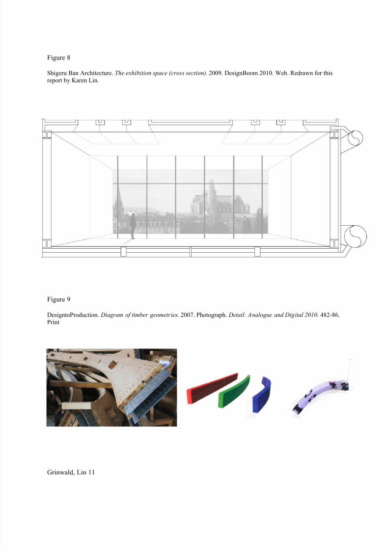
These extruded rectangles, each measuring 100-meter in length and fifteen-meter wide,
contain galleries and supporting program, cantilevered out and over the open forum space.
Structurally enabled by four steel beams (cross-section, figure 8.), one at each corner, creating a
parallelepipedic tube – in which its structure is extruded parallel to the rectangular base.
Conceptually, each cantilever offers specific, strategic views of the city of Metz. This structure
becomes essential to the architectural idea, developing the gallery as a continuous space
unobstructed by structure, cantilevered out of the building and into the city. All three spaces
intersect over a central core attached to the trussed spire, supported by the mast, internal steel,
and over 970 metric tons of reinforced concrete throughout the project (exclusive of the
foundation). The glazing at the end of each tube allows for the only source of natural lighting in
each of the three galleries, which utilize large curtains specially designed to control the amount
of direct natural light into each space. These cantilevered spaces puncture an additional system
of simple lightweight steel trusses and a glazed curtain wall system, which encloses the forum
space beneath the canopy and contains all additional program.
8/18/2019 Centre Pompidou Metz Final Report
http://slidepdf.com/reader/full/centre-pompidou-metz-final-report 4/19
Grinwald, Lin 4
PROCESSES AND METHODS OF MODELING:
The focus of the model was to accurately and precisely reproduce and investigate the
timber-lattice roof-canopy, structural mast or spire, timber-steel connections, Glulam pins and to
locate the eight foundation piles located at two of the primary piers, diagramming one of these
connections as a cut-away section detail. The program mass of the three cantilevers was formally
modeled as simple boxes and only implied the glazing in order to provide a formal context to
situate the canopy, mast and concrete slabs. Although the cantilevered, counter-weighted, system
is itself incredibly sophisticated, it is neither as structurally expressive, nor as characteristically
indicative of the project as both the mast and the canopy. The curtain wall system was omitted
from the model, as it is somewhat structurally independent of the canopy and would not develop
the clarity of the model or provide useful context or scale.
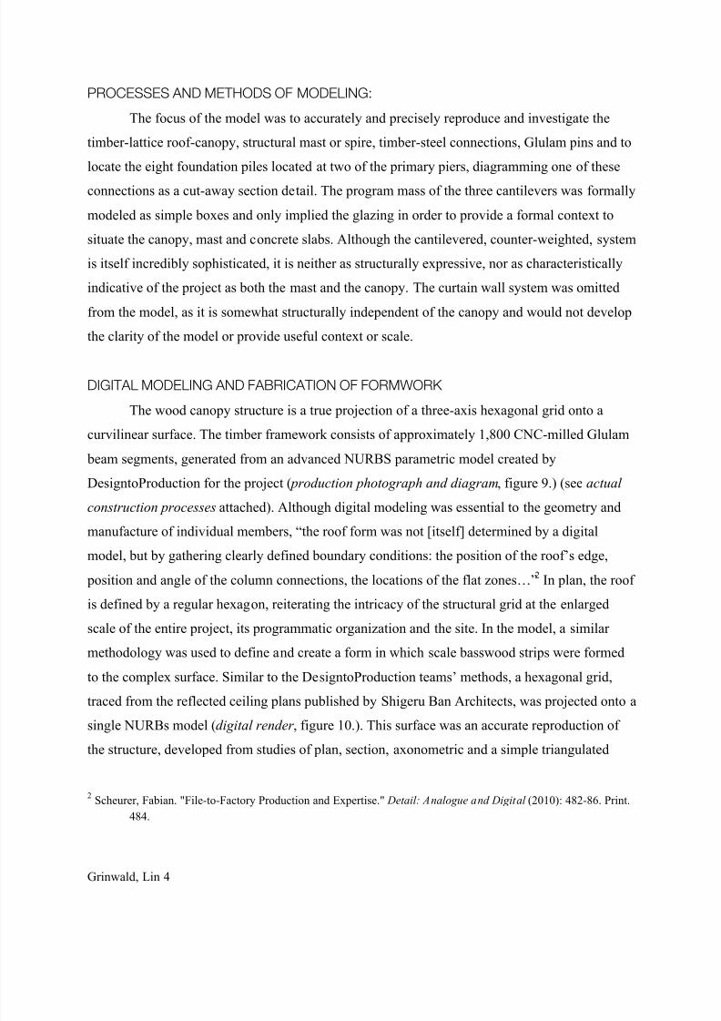
DIGITAL MODELING AND FABRICATION OF FORMWORK
The wood canopy structure is a true projection of a three-axis hexagonal grid onto a
curvilinear surface. The timber framework consists of approximately 1,800 CNC-milled Glulam
beam segments, generated from an advanced NURBS parametric model created by
DesigntoProduction for the project ( production photograph and diagram, figure 9.) (see actual
construction processes attached). Although digital modeling was essential to the geometry and
manufacture of individual members, “the roof form was not [itself] determined by a digitalmodel, but by gathering clearly defined boundary conditions: the position of the roof’s edge,
position and angle of the column connections, the locations of the flat zones…”2 In plan, the roof
is defined by a regular hexagon, reiterating the intricacy of the structural grid at the enlarged
scale of the entire project, its programmatic organization and the site. In the model, a similar
methodology was used to define and create a form in which scale basswood strips were formed
to the complex surface. Similar to the DesigntoProduction teams’ methods, a hexagonal grid,
traced from the reflected ceiling plans published by Shigeru Ban Architects, was projected onto a
single NURBs model (digital render , figure 10.). This surface was an accurate reproduction of
the structure, developed from studies of plan, section, axonometric and a simple triangulated
2 Scheurer, Fabian. "File-to-Factory Production and Expertise." Detail: Analogue and Digital (2010): 482-86. Print.
484.

8/18/2019 Centre Pompidou Metz Final Report
http://slidepdf.com/reader/full/centre-pompidou-metz-final-report 5/19
Grinwald, Lin 5
model using Rhinoceros 4.0. The regularity of the hexagonal grid deforms at the base of each
pier, and was three-dimensionally manipulated in the digital model to maintain the developed
surface according to photographic and sectional images.
This surface was patched using line-of-best-fit calculations (three-dimensional patch
commands) over the triangulated surface and between two-dimensional sections. The hexagonal
grip was then projected onto this initial surface, and then re-patched and joined to create a fluid
and continuous surface (digital render , figure 11.). This final surface was CNC-milled from a
high-density four-pound insulating foam, with one-eighth inch depressions milled to define the
doubly-curved path of each member. Where the surface became increasingly complex, a felt-tip
marker was used to CNC draw the path of each strip onto the surface, as using a convential drill
bit would damage the foam with the mill housing. The formwork was milled in two sections, and
glued together prior to assembly.
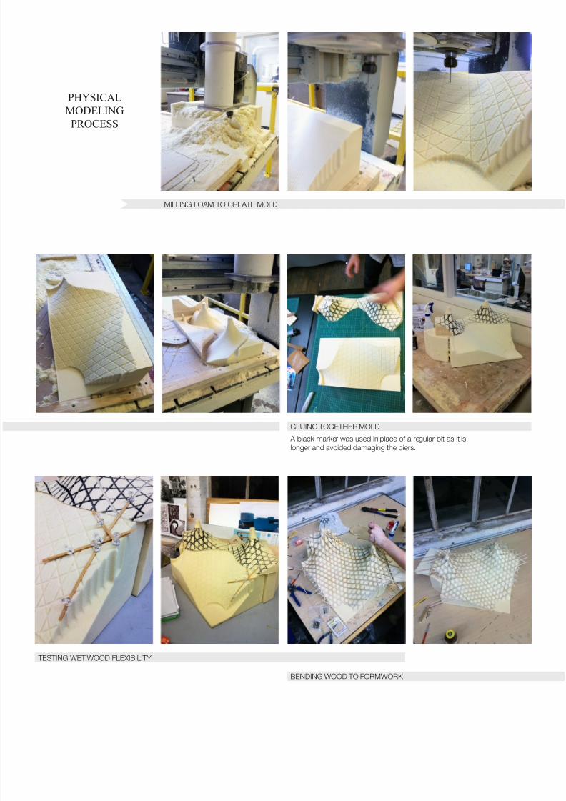
PHYSICAL MODELING
Scaled basswood strips (one-eighth inch on the long axis) were soaked in cold water for
several days to soften the wood fibers and improve the flexibility of the wood, both across the
shot and long axes to accommodate extreme double-curvature. After testing the basswood at
points of varying flexibility, strips were individually cut, sanded and glued into place, layer bylayer. At each layer, each node was pinned into the foam until it was dried into place and secured
with a small amount of wood glue. At each layer, pins were removed; the following layer was
attached and pinned back into place. Between each of the parallel layers, a series of basswood
spacers, cut and sanded to three-eights of an inch in length were individually glued alternating
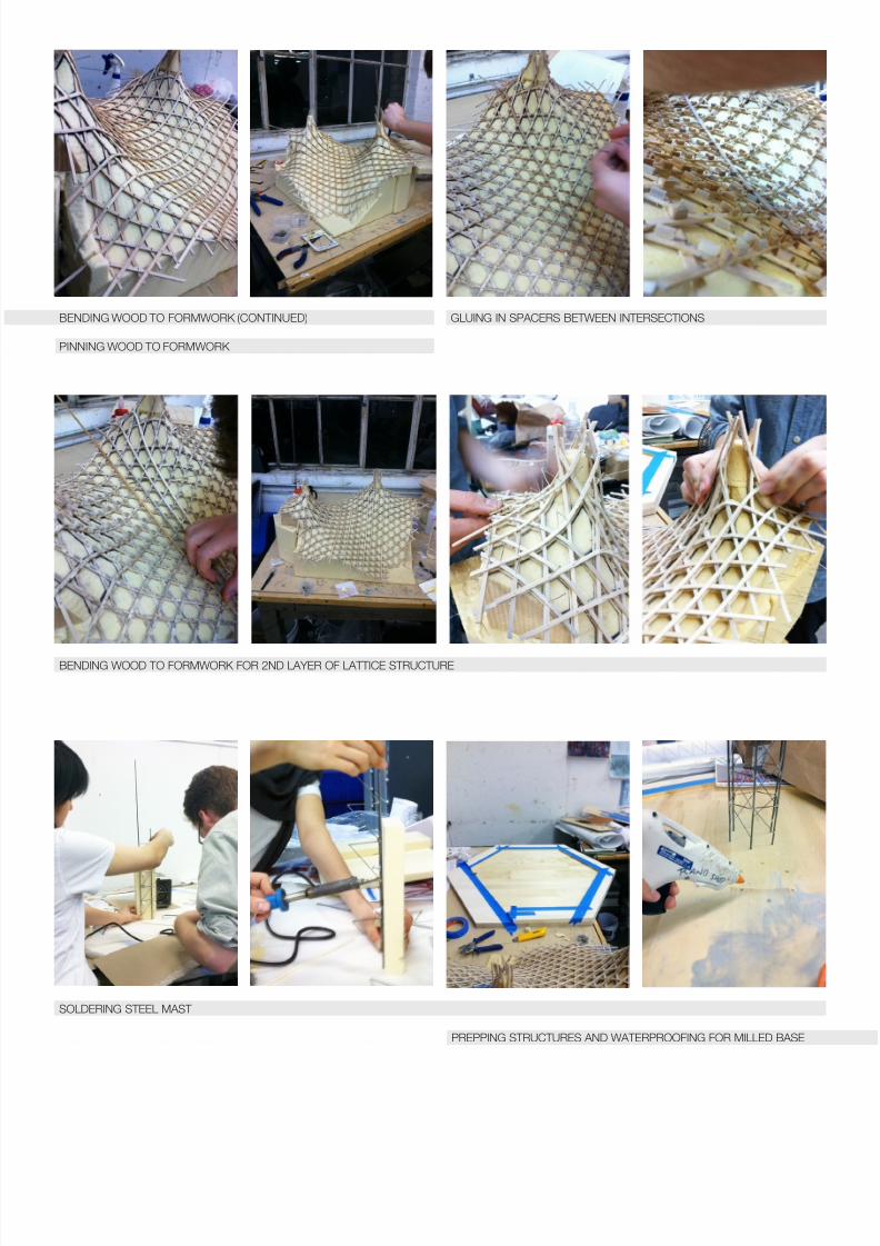
between each node, supporting the following layers. A total of six layers of basswood strips were
cut and formed to the prescribed geometry and three layers of wood spacers were glued into the
lattice. When the lattice was fully formed, inverted on the milled formwork, each pin was
removed and the canopy lifted off of the form. Pins were re-inserted into the holes at each node
and cut to the thickness of the completed canopy. To complete the structure, basswood eaves
were glued and clamped over the edge conditions and the structure was completely sanded to
smooth out irregular curvatures. Methodologically, the model-making process is very similar to
the construction at the full-scale, assembled layer by layer and secured with pin connections.
8/18/2019 Centre Pompidou Metz Final Report
http://slidepdf.com/reader/full/centre-pompidou-metz-final-report 6/19
Grinwald, Lin 6
However, unlike the CNC-milled timber used in the completed project, only the inverse surface
geometry was digitally fabricated to ensure accuracy. The entirety of the presentation model,
apart from the milled base, was hand-crafted.
SCALE
The model represents only a section – approximately one fourth – of the timber roof
canopy, from the two piers facing the project’s main entrance and spanning to the spire
connection. Given the formal complexity of the project and the precise iteration of its hexagonal
module, the model is investigates the formal, methodological and technical development of this
surface. Members were layered, spaced and laminated in a way that conveyed the structural
concept of the project at a resolution appropriate to the scale: approximately one-twelfth of an
inch is equal to one foot (one-eighth of an inch equals 44 centimeters). At this scale, some of the
detail of the structural connections was appropriately abstracted. Pins were placed at each node
of the canopy, but are simple metal pin connections reinforced with glue rather than doweled
pre-stressed connections. Laminated members were modeled as single-ply one-eighth inch
basswood strips. Basswood elements were cut to a lapped edge and meet the mast at a scale
plastic ring attached to the truss work and secured with simple metal clips. For the sake of
clarity, the PTFE membrane was not modeled, as it would require a development of the entire
roof geometry and may have obscure the detail of the canopy model itself. Where both piersIndependent of the continuous canopy, a small section of the lattice was modeled at a third pier,
detailing the connection to the pier to the concrete slab and pile caps as a cut-away section. The
completed canopy and soldered mast were attached to the milled base and secured into place
with a quarter-inch thick Rockite slab. During the casting process, a piece of foam was used to
complete the base relief. After the Rockite had set, the foam was removed to reveal a cross-
section of the slab, into which the foundation connections were simply modeled. The process and
production of the model were carefully documented to clarify the translation of full-scale
mythologies, as well as the abstraction of structural details, to those appropriate for the scale of
the model (see physical modeling process attached).
Structural expression and methodological precision are essential to a fundamentally
architectural understanding of the Centre Pompidou-Metz. The model attempts to inventory
8/18/2019 Centre Pompidou Metz Final Report
http://slidepdf.com/reader/full/centre-pompidou-metz-final-report 7/19
Grinwald, Lin 7
those processes and investigate the formal and structural complexities of the project in a way that
clarifies the interplay between structural detail, modular distortion and architectural affect. The
processes of model making, digital modeling and fabrication and methods of representation
helped to develop a hands-on approach toward structural analysis that served to reinforce
structurally systemic and architecturally conceptual readings of the Centre Pompidou-Metz.
8/18/2019 Centre Pompidou Metz Final Report
http://slidepdf.com/reader/full/centre-pompidou-metz-final-report 8/19
Grinwald, Lin 8
Figure 2
Mossot, Jacques. Doweled Pin Connection. 2007. Photograph. Nicholas Janberg's Structurae. Print. Ser. 128039.
FIGURES CITED
Figure 1
Connection Detail and Structural Diagram. 2007. Image. Contractors World 2010. 7th ed. Vol. 1. 21-25. Print. Note,
images in actual construction processes attachment appear in this article.
8/18/2019 Centre Pompidou Metz Final Report
http://slidepdf.com/reader/full/centre-pompidou-metz-final-report 9/19
Grinwald, Lin 9
Figure 3
Section of Pier Footing . 2008. Image.
Detail: Timber Construction 2010. 1040-
045. Print.
Figure 4
Detail of Membrane Connection. 2010.
Photograph. Contractors World 2010. 7th ed. Vol.
1. 21-25. Print
8/18/2019 Centre Pompidou Metz Final Report
http://slidepdf.com/reader/full/centre-pompidou-metz-final-report 10/19
Grinwald, Lin 10
Figures 5, 6, and 7
Detail and Diagram of Steel-to-Timber Connection at Mast, and Section Through Connection. 2008. Photograph. Detail: Timber Construction 2010. 1040-045. Print.
8/18/2019 Centre Pompidou Metz Final Report
http://slidepdf.com/reader/full/centre-pompidou-metz-final-report 11/19
Grinwald, Lin 11
Figure 8
Shigeru Ban Architecture. The exhibition space (cross section). 2009. DesignBoom 2010. Web. Redrawn for this
report by Karen Lin.
Figure 9
DesigntoProduction. Diagram of timber geometries. 2007. Photograph. Detail: Analogue and Digital 2010 . 482-86.

8/18/2019 Centre Pompidou Metz Final Report
http://slidepdf.com/reader/full/centre-pompidou-metz-final-report 12/19
Grinwald, Lin 12
Figure 10
DesigntoProduction. Digital Model of Parametric Surface . 2007. Image. Detail: Analogue and Digital 2010 . 482-
86. Print
Figure 11
Three-dimensional model and inverted milling file; created using Rhinoceros 4.0.
8/18/2019 Centre Pompidou Metz Final Report
http://slidepdf.com/reader/full/centre-pompidou-metz-final-report 13/19
Grinwald, Lin 13
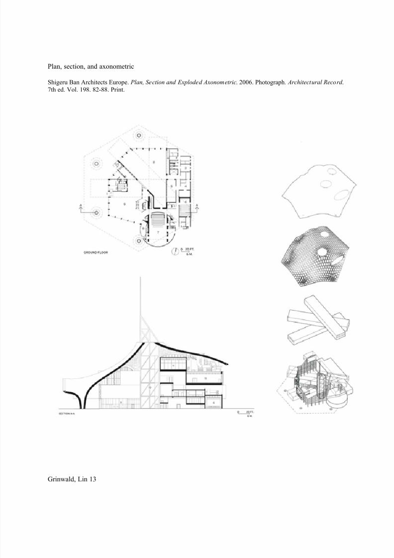
Plan, section, and axonometric
Shigeru Ban Architects Europe. Plan, Section and Exploded Axonometric. 2006. Photograph. Architectural Record .
7th ed. Vol. 198. 82-88. Print.
8/18/2019 Centre Pompidou Metz Final Report
http://slidepdf.com/reader/full/centre-pompidou-metz-final-report 14/19
ACTUAL
CONSTRUCTION
PROCESS
CNC MILLING
PINNING INTO PLACE
FITTING DOWELED PIN CONNECTION INSERTING CONNECTION PLATES
8/18/2019 Centre Pompidou Metz Final Report
http://slidepdf.com/reader/full/centre-pompidou-metz-final-report 15/19
PHYSICAL
MODELING
PROCESS
MILLING FOAM TO CREATE MOLD
GLUING TOGETHER MOLD
A black marker was used in place of a regular bit as it is
longer and avoided damaging the piers.
TESTING WET WOOD FLEXIBILITY
BENDING WOOD TO FORMWORK
8/18/2019 Centre Pompidou Metz Final Report
http://slidepdf.com/reader/full/centre-pompidou-metz-final-report 16/19
PINNING WOOD TO FORMWORK
GLUING IN SPACERS BETWEEN INTERSECTIONS
BENDING WOOD TO FORMWORK FOR 2ND LAYER OF LATTICE STRUCTURE
SOLDERING STEEL MAST
PREPPING STRUCTURES AND WATERPROOFING FOR MILLED BASE
BENDING WOOD TO FORMWORK (CONTINUED)
8/18/2019 Centre Pompidou Metz Final Report
http://slidepdf.com/reader/full/centre-pompidou-metz-final-report 17/19
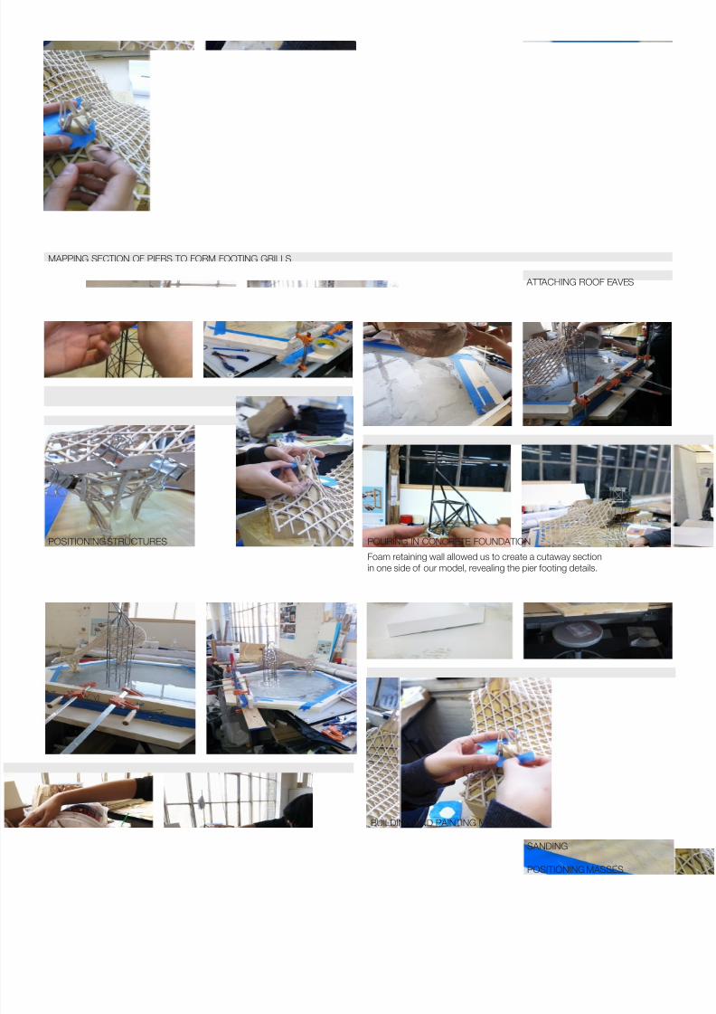
MAPPING SECTION OF PIERS TO FORM FOOTING GRILLS
POSITIONING STRUCTURES
BUILDING AND PAINTING MASSES
SANDING
POSITIONING MASSES
POURING IN CONCRETE FOUNDATION
ATTACHING ROOF EAVES
Foam retaining wall allowed us to create a cutaway section
in one side of our model, revealing the pier footing details.
8/18/2019 Centre Pompidou Metz Final Report
http://slidepdf.com/reader/full/centre-pompidou-metz-final-report 18/19
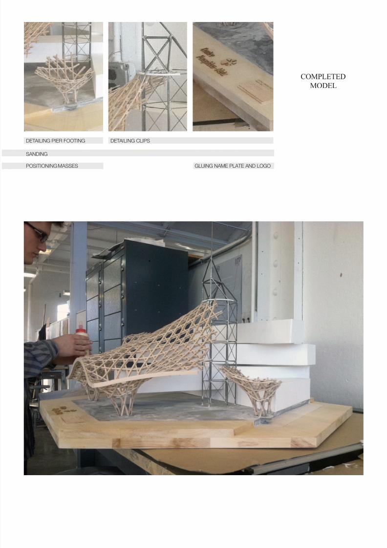
COMPLETED
MODEL
POSITIONING MASSES
DETAILING PIER FOOTING DETAILING CLIPS
GLUING NAME PLATE AND LOGO
SANDING

8/18/2019 Centre Pompidou Metz Final Report
http://slidepdf.com/reader/full/centre-pompidou-metz-final-report 19/19
WORKS CITED
Bidaine, Philippe. Centre Pompidou-Metz . Paris: Nouv. Éd. Scala, 2010. Print.
"The Building." Centre Pompidou-Metz . Web. 12 Mar. 2011. <http://www.centrepompidou-metz.fr/site/?-the-building->.
Chessa, Melina. "Centre Pompidou-Metz : Les Premières Poutres De La Charpente Bois SontPosées." Lemoniteur.fr . Le Moniteur France, 1 Apr. 2009. Web. 13 Mar. 2011.CenterPompidou-Metz : The First Beams of the Wooden Frame are Positioned
"Centre Pompidou-Metz." Detail: Timber Construction (2010): 1040-045. Print.
"Centre Pompidou Metz." Structurae. Nicolas Janberg's Structurae, 2011. Web. 12 Mar. 2011.<http://en.structurae.de/structures/data/index.cfm?id=s0012274>.
"Centre Pompidou Metz : 2008." Design to Production. Design to Production: Zurich/Stuttgart,
June 2008. Web. 11 Mar. 2011.<http://www.designtoproduction.ch/content/view/75/54/>.
"Centre Pompidou Metz - France, 2010." Shigeru Ban Architects. Web. 11 Mar. 2011.<http://www.shigerubanarchitects.com/SBA_WORKS/SBA_OTHERS/SBA_OTHERS_ 30/SBA_others_30.html>.
Contractor World, and Holzbau Amann. "France: Outstanding Architectural Design Is Challengefor Contractor." Contractors World 1.7 (2010): 21-25. Contractors World . Roger Lindley,May 2010. Web. 12 Mar. 2011.
Harris, James B., and Kevin Pui-K. Li. Masted Structures in Architecture. Oxford: Butterworth
Architecture, 1996. Print.Jodidio, Philip, and Bon Laurent. Le. Centre Pompidou - Metz . Paris: Centre Pompidou, 2008.
Print.
Jodidio, Philip, and Shigeru Ban. Shigeru Ban: Complete Works, 1985-2010. Köln: Taschen,2010. Print.
Lequeux, Emmanuelle. L'architecture Du Musée: Chefs-d'oeuvre Du XXe Siècle. Paris: BeauxArts-TTM, 2010. Print.
Moore, Rowan. "Under the Big Top." Architectural Record 198.7 (2010): 82-88. Print.
Scheurer, Fabian. "File-to-Factory Production and Expertise." Detail: Analogue and Digital (2010): 482-86. Print.


![940 Aavv (2002) [Centre Pompidou] La Révolution surréaliste.pdf](https://img.pdfslide.us/doc/110x75/55cf9d43550346d033ace110/940-aavv-2002-centre-pompidou-la-revolution-surrealistepdf.jpg)