Embed Size (px)
Citation preview
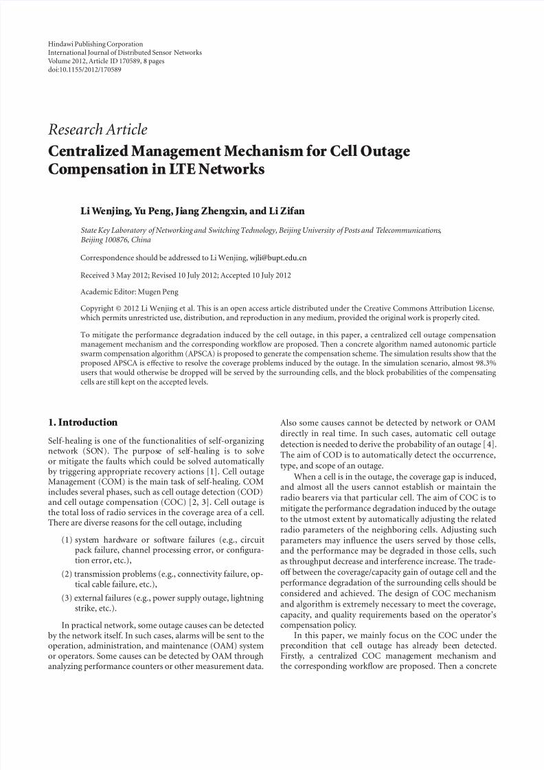
7/29/2019 CentralizedManagementMechanism for Cell Outage
http://slidepdf.com/reader/full/centralizedmanagementmechanism-for-cell-outage 1/8
Hindawi Publishing CorporationInternational Journal of Distributed Sensor NetworksVolume 2012, Article ID 170589, 8 pagesdoi:10.1155/2012/170589
Research ArticleCentralizedManagementMechanism for Cell OutageCompensation in LTENetworks
LiWenjing, Yu Peng, Jiang Zhengxin, and Li Zifan
State Key Laboratory of Networking and Switching Technology, Beijing University of Posts and Telecommunications,Beijing 100876, China
Correspondence should be addressed to Li Wenjing, [email protected]
Received 3 May 2012; Revised 10 July 2012; Accepted 10 July 2012
Academic Editor: Mugen Peng
Copyright © 2012 Li Wenjing et al. This is an open access article distributed under the Creative Commons Attribution License,which permits unrestricted use, distribution, and reproduction in any medium, provided the original work is properly cited.
To mitigate the performance degradation induced by the cell outage, in this paper, a centralized cell outage compensationmanagement mechanism and the corresponding workflow are proposed. Then a concrete algorithm named autonomic particleswarm compensation algorithm (APSCA) is proposed to generate the compensation scheme. The simulation results show that theproposed APSCA is eff ective to resolve the coverage problems induced by the outage. In the simulation scenario, almost 98.3%users that would otherwise be dropped will be served by the surrounding cells, and the block probabilities of the compensatingcells are still kept on the accepted levels.
1. Introduction
Self-healing is one of the functionalities of self-organizingnetwork (SON). The purpose of self-healing is to solveor mitigate the faults which could be solved automatically by triggering appropriate recovery actions [1]. Cell outageManagement (COM) is the main task of self-healing. COMincludes several phases, such as cell outage detection (COD)and cell outage compensation (COC) [2, 3]. Cell outage isthe total loss of radio services in the coverage area of a cell.There are diverse reasons for the cell outage, including
(1) system hardware or software failures (e.g., circuitpack failure, channel processing error, or configura-tion error, etc.),
(2) transmission problems (e.g., connectivity failure, op-tical cable failure, etc.),
(3) external failures (e.g., power supply outage, lightningstrike, etc.).
In practical network, some outage causes can be detectedby the network itself. In such cases, alarms will be sent to theoperation, administration, and maintenance (OAM) systemor operators. Some causes can be detected by OAM throughanalyzing performance counters or other measurement data.
Also some causes cannot be detected by network or OAMdirectly in real time. In such cases, automatic cell outage
detection is needed to derive the probability of an outage [4].The aim of COD is to automatically detect the occurrence,type, and scope of an outage.
When a cell is in the outage, the coverage gap is induced,and almost all the users cannot establish or maintain theradio bearers via that particular cell. The aim of COC is to
mitigate the performance degradation induced by the outageto the utmost extent by automatically adjusting the relatedradio parameters of the neighboring cells. Adjusting such
parameters may influence the users served by those cells,and the performance may be degraded in those cells, suchas throughput decrease and interference increase. The trade-off between the coverage/capacity gain of outage cell and theperformance degradation of the surrounding cells should beconsidered and achieved. The design of COC mechanism
and algorithm is extremely necessary to meet the coverage,capacity, and quality requirements based on the operator’scompensation policy.
In this paper, we mainly focus on the COC under theprecondition that cell outage has already been detected.Firstly, a centralized COC management mechanism andthe corresponding workflow are proposed. Then a concrete
7/29/2019 CentralizedManagementMechanism for Cell Outage
http://slidepdf.com/reader/full/centralizedmanagementmechanism-for-cell-outage 2/8
2 International Journal of Distributed Sensor Networks
algorithm named autonomic particle swarm compensationalgorithm (APSCA) is proposed to generate the parameteradjustment scheme. APSCA is used to compensate thecoverage gap induced by the outage while considering thebalance between coverage/capacity and quality. At last, theachieved performance eff ects are evaluated.
The rest of this paper is organized as follows. Section 2introduces the related works about COC. Section 3 proposesthe centralized COC management mechanism and corre-sponding workflow. In Section 4, the COC algorithm APSCAis described and the complexity is analyzed, followed by thesimulation results and discussion in Section 5. The paper isconcluded in Section 6, where we conclude the current work and present a prospect of the future work.
2. RelatedWorks
In 3GPP TS 32.541 [1], the general steps of automatic celloutage recovery and cell outage compensation are presented,but no any concrete COC algorithm is presented. Thenetwork parameters that can be adjusted by COC includecell reference signal transmission power P RS, antenna tiltor azimuth, uplink target received power level P 0, andmobility parameters. In paper [5], a quantitative analysis of the compensation potential of diff erent control parametersin mitigating outage-induced performance degradations inLTE networks is presented. In paper [6], a framework forautomatic cell outage management and the key compo-nents necessary to detect and compensate the outages arepresented. But no concrete compensation algorithms areproposed in [5, 6] yet.
In paper [7], an automated coverage optimization algo-rithm is proposed to optimize wireless downlink coverage inthe RAN. However, the algorithm is based on the long-termmeasurements and analysis which is suitable for the normalnetwork optimization scenario, but not suitable for the real-time cell outage compensation scenario. In papers [8–11],the algorithms, respectively, adjusting pilot power, targetreceived power density, or antenna tilt of the surroundingcells to compensate the coverage gap are proposed. But thesealgorithms are all based on the stepwise adjustment methodsin which the control parameters are consecutively adjustedstep by step. After each step the system performance shouldbe evaluated and then go to the next adjustment step until the
compensation objective is reached. The convergence speed of those stepwise adjustment algorithms is comparatively fast,but the interim parameters may not be suitable and willusually bring instability to the system.
In this paper, we present a framework for centralizedCOC management mechanism and propose a heuristic COCalgorithm for LTE networks, which is named AutonomicParticle Swarm Compensation Algorithm (APSCA). By APSCA, the final optimal parameter adjustment scheme canbe automatically generated by the centralized node. APSCAcan overcome shortcomings of the previous work, and theconvergence speed is rapid enough to meet the real-timerequirements of COC.
3. Centralized COCManagementMechanism
When a cell is out of the service, the control parametersof the surrounding cells need be adjusted to implementthe coverage compensation and guarantee the quality of network service. Several factors should be considered whenadjusting the control parameters, such as traffic load, amountof users, interference, downlink reference signal transmissionpower, uplink target received power, and antenna patterns.If the distributed COC management framework is adopted,large numbers of data need be exchanged among diff erenteNodeBs, which will greatly increase the complexity of theCOC algorithm and the difficulty of the implementation.As such, a centralized COC management framework is pro-posed in the paper. In the framework, it is the responsibility of OAM to collect and process all kinds of data and generatethe final adjustment scheme. The centralized framework ismore suitable for COC features.
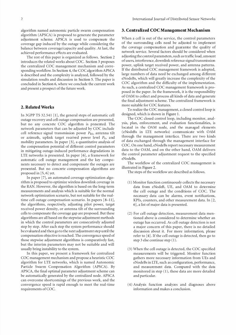
To realize the COC management, a closed control loop isdesigned, which is shown in Figure 1.
The COC closed control loop, including monitor, anal- ysis, plan, enforcement, and evaluation functionalities, islocated in the OAM node, and the managed elements(eNodeBs in LTE networks) communicate with OAMthrough the management interface. There are two kindsof data exchanged through the management interface forCOC. On one hand, eNodeBs report necessary measurementdata to the OAM, and on the other hand, OAM deliversthe control parameter adjustment request to the specifiedeNodeBs.
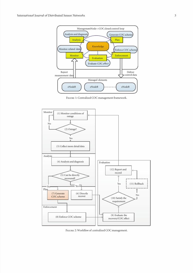
The workflow of the centralized COC management isillustrated in Figure 2.
The steps of the workflow are described as follows.
(1) Monitor function continuously collects the necessary data from eNodeB, UE, and OAM to determinethe cell outage and the conditions of COC. Thenecessary data can be alarms, event notifications,KPIs, counters, and other measurement data. In [2,6], a list of major data is presented.
(2) For cell outage detection, measurement data men-tioned above is considered to determine whether anoutage has occurred. As cell outage detection is nota major concern of this paper, there is no detaileddiscussion about it. For more information, please
refer to [4]. If the cell outage is detected, then go tostep 3 else continue step (1).
(3) When the cell outage is detected, the COC specifiedmeasurements will be triggered. Monitor functiongathers more necessary information from UEs andeNodeBs in LTE, such as configuration, performance,and measurement data. Compared with the datamonitored in step (1), these data are more detailedand particular.
(4) Analysis function analyzes and diagnoses aboveinformation and makes a conclusion.
7/29/2019 CentralizedManagementMechanism for Cell Outage
http://slidepdf.com/reader/full/centralizedmanagementmechanism-for-cell-outage 3/8
International Journal of Distributed Sensor Networks 3
Monitor
Analysis and diagnosis
Analysis
Generate COC scheme
Plan
Enforce COC scheme
Enforcement
Evaluate COC eff ect
Evaluation
Knowledge
Managed elements
Report
measurement data
Delivercontrol data
ManagementNode—COC closed control loop
eNodeBeNodeBeNodeB
Monitor-related data
Figure 1: Centralized COC management framework.
Evaluation
Enforcement
Plan
Monitor
Analysis
(1) Monitor conditions of outage
(9) Evaluate the
recovery/COC eff ect
(10) Satisfy the
requirement
(12) Report and
record
Yes
Yes
No
No
(3) Collect more detail data
YesNo
(6) Directly recover
(2) Outage?
(4) Analysis and diagnosis
(5) Can be directly
recovered?
(8) Enforce COC scheme
(7) Generate
COC scheme
(11) Rollback
Figure 2: Workflow of centralized COC management.
7/29/2019 CentralizedManagementMechanism for Cell Outage
http://slidepdf.com/reader/full/centralizedmanagementmechanism-for-cell-outage 4/8
4 International Journal of Distributed Sensor Networks
(5) If the conclusion shows that the problem can bedirectly recovered, then go to step (6); else go to step(7).
(6) The network elements directly recover the problemwhich is not discussed in this paper. When therecovery action is finished, then go to step (9).
(7) To mitigate the influence of the cell outage andguarantee the QoS of users, COC will be triggered totake appropriate actions. A COC scheme generationalgorithm named Autonomic Particle Swarm Com-pensation Algorithm (APSCA) is proposed, whichwill be discussed in detail in Section 4.
(8) After the COC scheme is generated, the enforcementfunction executes the COC scheme by deliveringthe parameter adjustment request to the specifiedeNodeBs. It should be noted that it is the eNodeBsthat really adjust the control parameters according tothe request.
(9) After recovery or COC, the evaluation functionbegins to assess the performance improvementbrought by the recovery or COC. It is necessary toclarify the criteria to evaluate to what extent thecompensation actions have reached in meeting theoptimization goals. The COC evaluation criteria aregiven in Section 4.1.
(10) If the problems are recovered or the COC meets therequirements, then go to step (12), else go to step(11).
(11) If the problems are not recovered, then execute therollback process when required.
(12) Report the COC enforcement result. OAM can record
the necessary information according to the require-ments. Then go to step (1) to continue monitoringthe related data.
4. COCAlgorithm
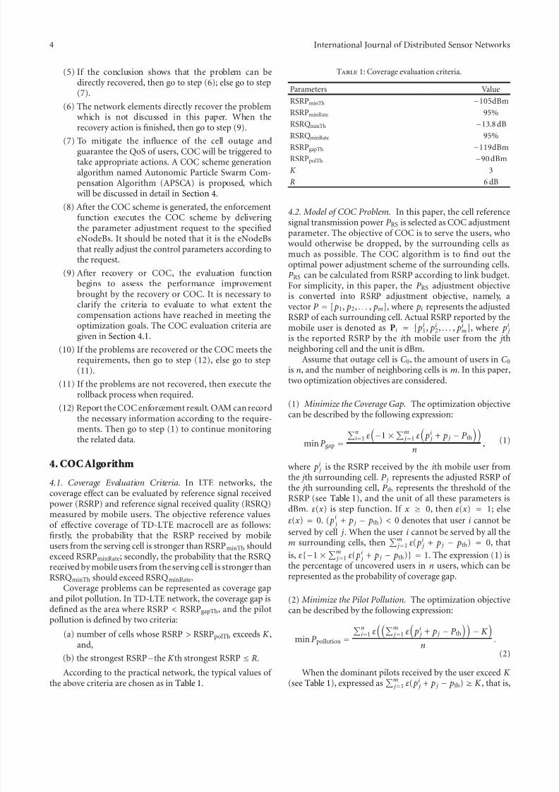
4.1. Coverage Evaluation Criteria. In LTE networks, thecoverage eff ect can be evaluated by reference signal receivedpower (RSRP) and reference signal received quality (RSRQ)measured by mobile users. The objective reference valuesof eff ective coverage of TD-LTE macrocell are as follows:firstly, the probability that the RSRP received by mobileusers from the serving cell is stronger than RSRPminTh should
exceed RSRPminRate; secondly, the probability that the RSRQreceived by mobile users from the serving cell is stronger thanRSRQminTh should exceed RSRQminRate.
Coverage problems can be represented as coverage gapand pilot pollution. In TD-LTE network, the coverage gap isdefined as the area where RSRP < RSRPgapTh, and the pilotpollution is defined by two criteria:
(a) number of cells whose RSRP > RSRPpolTh exceeds K ,and,
(b) the strongest RSRP−the K th strongest RSRP ≤ R.
According to the practical network, the typical values of the above criteria are chosen as in Table 1.
Table 1: Coverage evaluation criteria.
Parameters Value
RSRPminTh −105dBm
RSRPminRate 95%
RSRQminTh −13.8 dB
RSRQminRate 95%RSRPgapTh −119dBm
RSRPpolTh −90 dBm
K 3
R 6 dB
4.2. Model of COC Problem. In this paper, the cell referencesignal transmission power P RS is selected as COC adjustmentparameter. The objective of COC is to serve the users, whowould otherwise be dropped, by the surrounding cells asmuch as possible. The COC algorithm is to find out theoptimal power adjustment scheme of the surrounding cells.
P RS can be calculated from RSRP according to link budget.For simplicity, in this paper, the P RS adjustment objectiveis converted into RSRP adjustment objective, namely, avector P = [ p1, p2, . . . , pm], where pi represents the adjustedRSRP of each surrounding cell. Actual RSRP reported by themobile user is denoted as Pi = [ pi1, pi2, . . . , pim], where pi jis the reported RSRP by the ith mobile user from the j thneighboring cell and the unit is dBm.
Assume that outage cell is C 0, the amount of users in C 0is n, and the number of neighboring cells is m. In this paper,two optimization objectives are considered.
(1) Minimize the Coverage Gap. The optimization objective
can be described by the following expression:
minP gap =
ni=1 ε
−1 ×
m j=1 ε
pi j + p j − P th
n, (1)
where pi j is the RSRP received by the ith mobile user fromthe j th surrounding cell. P j represents the adjusted RSRP of the j th surrounding cell, P th represents the threshold of theRSRP (see Table 1), and the unit of all these parameters isdBm. ε(x ) is step function. If x ≥ 0, then ε(x ) = 1; else
ε(x ) = 0. ( pi j + p j − pth) < 0 denotes that user i cannot be
served by cell j. When the user i cannot be served by all them surrounding cells, then
m j=1 ε( pi j + p j − pth) = 0, that
is, ε{−1 ×
m j=1 ε( pi j + p j − pth)} = 1. The expression (1) isthe percentage of uncovered users in n users, which can berepresented as the probability of coverage gap.
(2) Minimize the Pilot Pollution. The optimization objectivecan be described by the following expression:
minP pollution =
ni=1 ε
m j=1 ε
pi j + p j − P th
− K
n.
(2)
When the dominant pilots received by the user exceed K (see Table 1), expressed as
m j=1 ε( pi j + p j − pth) ≥ K , that is,
7/29/2019 CentralizedManagementMechanism for Cell Outage
http://slidepdf.com/reader/full/centralizedmanagementmechanism-for-cell-outage 5/8
International Journal of Distributed Sensor Networks 5
ε{{m
j=1 ε( pi j + p j − pth)} −K } = 1. The expression (2) is thepercentage of pilot pollution users in n users, which can berepresented as the probability of pilot pollution.
According to the expressions (1) and (2), the optimiza-tion problem is a multiobjective nonlinear optimizationproblem. In the paper, an Autonomic Particle Swarm
Compensation Algorithm (APSCA) is proposed to solve it.APSCA is suitable for multiobjective optimization problemsand especially suitable for COC scenario because of the highspeed of convergence.
4.3. APSCA Description. In APSCA, the surrounding cells areregarded as particle swarm. To find the optimal referencesignal transmission powers of surrounding cells is equivalentto finding the optimal positions of particle swarm. Supposethe particle swarm includes m particles. APSCA defineseach particle in the D-dimensional space. The location andvelocity of the particles are, respectively, denoted as vector X i = (x i1, x i2, . . . , x id ) and V i = (v i1, v i2, . . . , v id ) where i =
1,2, . . . ,m. The previous best position of a single particle isdenoted as P i = ( pi1, pi2, . . . , pid ), and the previous globalbest position of the particle swarm is denoted as P g =
( p g 1, p g 2, . . . , p gd ).Before finding the best position, the particles update their
velocity and position according to the following formulae:
v id = v id · w + c1 · r pid − x id
+ c2 · r
p gd − x id
, (3)
x id = x id + v id , (4)
where w is the constant inertia factor, c1 and c2 areacceleration coefficients, and r is a random number between(0, 1). We choose expressions (1) and (2) as fitness functions
of particle i and choose the objective reference values of eff ective coverage listed in Table 1 as objective optimizationcriteria.
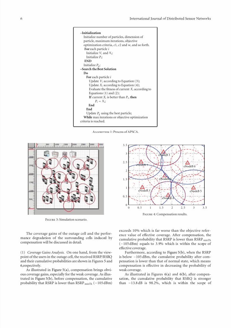
The process of APSCA is described in Algorithm 1.
4.4. Complexity Analysis of APSCA. According to the paper[12], the APSCA is convergent if the algorithm parameters(c1, c2, andw) are given appropriate values.
In APSCA, the number of particles in the swarm is mwhich denotes the number of surrounding cells, and thedimension of each particle is D. The time complexity of APSCA is calculated as follows.
(1) The time complexity of initialization is O(mD).(2) In each iteration, the time complexity to update the
location and velocity for all particles is O(mD).
(3) In each iteration, the time complexity to calculatethe fitness function is O(nmD), where n denotes thenumber of original users located in the outage area.
(4) In each iteration, the time complexity to update theoptimal particle is O(m).
(5) In each iteration, the time complexity to update theglobal optimal particle swarm is O(m).
(6) Suppose the iteration times is N ; then the total timecomplexity is represented as O[mD + N ∗ (nmD +
Table 2: Key simulation system parameters.
Parameters Value
Carrier frequency 2.6GHz
Inter-eNodeB distance 500 m
System bandwidth 20 MHz (100 RB)
Antenna mode 3 GPP 3D ModelAntenna downtilt 15◦
Channel mode Typical urban
Maximum eNodeB output power 46 dBm
Maximum UE output power 23 dBm
Path loss from Macro to UEL = 128.1 +
37.6log10 (R) (Unit of R iskm)
Std deviation of shadow fading −8 dB
Penetration loss 20dB
UE density across macrocells Uniform distribution
UE distribution within a macrocell Uniform distribution
Service rate of edge users 128 kbps (UL), 512 kbps(DL)
mD + 2m)] which can be approximately representedas O(NnmD), where m is not more than 7 and D isnot more than 2 in COC scenario.
Based on the previous analysis, the time efficiency of thealgorithm is high. The APSCA is suitable for the centralizedCOC management scenario.
5. Simulation andDiscussion
The compensation eff ect of the APSCA is validated in theTD-LTE scenario using Qualnet and Matlab. The simulationshows APSCA can eff ectively solve the coverage probleminduced by cell outage while the performance degradationof compensating cells can be kept on the accepted levels.
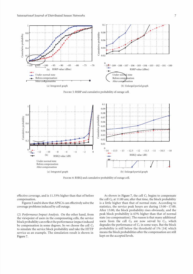
5.1. Simulation Parameters Configuration. The simulationscenario is a TD-LTE urban macrocell region of 3.5 km ×
3.5 km. Top view of simulation environment is shown inFigure 3 . In the simulation scenario, there are 7 eNodeBswith space about 500 m and about 300 users randomly scattered in the area which are not totally shown in the figure.
Refer to [13]; the key simulation system parameters areconfigured as Table 2.
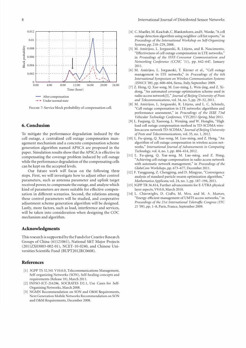
5.2. Simulation Results and Discussion. Assume thateNodeB0 (and the corresponding cell C 0) which is located inthe middle of the region is in the outage. Figure 4 shows thesimulation results of cell outage compensation by APSCA.
By calculating the simulation data, we can learn thatalmost 98.3% of the coverage area of the cell C 0 is coveredby the surrounding cells after compensation. Among thecompensating cells, cells C 3 and C 6 are the most two cells tocompensate the cell C 0, while other surrounding cells makethe minor contribution to compensation.
7/29/2019 CentralizedManagementMechanism for Cell Outage
http://slidepdf.com/reader/full/centralizedmanagementmechanism-for-cell-outage 6/8
6 International Journal of Distributed Sensor Networks
–Initialization
Initialize number of particles, dimension of particle, maximum iterations, objectiveoptimization criteria, c1 , c2 and w, and so forth.For each particle i
Initialize V i and X i ;
Initialize P i ;END
Initialize P g ;–Search the Best Solution
Do
For each particle iUpdate V i according to Equation (3);Update X i according to Equation (4);Evaluate the fitness of current X i according toEquations (1) and (2);If current X i is better than P i , then
P i = X i ;End
End
Update P g using the best particle;While max iterations or objective optimizationcriteria is reached.
Algorithm 1: Process of APSCA.
Figure 3: Simulation scenario.
The coverage gains of the outage cell and the perfor-mance degradation of the surrounding cells induced by compensation will be discussed in detail.
(1) Coverage Gains Analysis. On one hand, from the view-point of the users in the outage cell, the received RSRP/RSRQand their cumulative probabilities are shown in Figures 5 and6,respectively.
As illustrated in Figure 5(a), compensation brings obvi-ous coverage gains, especially for the weak coverage. As illus-trated in Figure 5(b), before compensation, the cumulativeprobability that RSRP is lower than RSRPminTh (−105 dBm)
0 0. 5 1 1. 5 2 2. 5 3 3. 50
0. 5
1
1. 5
2
2. 5
3
3. 5
eNodeB 0
eNodeB 1
eNodeB 2
eNodeB 3
eNodeB 4
eNodeB 5
eNodeB 6
Figure 4: Compensation results.
exceeds 10% which is far worse than the objective refer-ence value of eff ective coverage. After compensation, thecumulative probability that RSRP is lower than RSRPminTh
(−105 dBm) equals to 3.9% which is within the scope of eff ective coverage.
Furthermore, according to Figure 5(b), when the RSRPis below −105 dBm, the cumulative probability after com-pensation is lower than that of normal state, which meanscompensation is eff ective in decreasing the probability of weak coverage.
As illustrated in Figures 6(a) and 6(b), after compen-sation, the cumulative probability that RSRQ is strongerthan −13.8 dB is 98.2%, which is within the scope of
7/29/2019 CentralizedManagementMechanism for Cell Outage
http://slidepdf.com/reader/full/centralizedmanagementmechanism-for-cell-outage 7/8
International Journal of Distributed Sensor Networks 7
(b)
−110 −105 −100 −95 −90 −85 −80 −75 −700
0.2
0.4
0.6
0.8
1
C u m u
l a t i v e p r o
b a
b i l i t y
Under normal state
Before compensation
After compensation
RSRP value (dBm)
(a) Integrated graph
−110 −109 −108 −107 −106 −105 −104 −103 −102 −101 −1000
0.02
0.04
0.06
0.08
0.1
RSRP value (dBm)
C u m u l a t i v e p r o
b a
b i l i t y
Under normal state
Before compensation
After compensation
(b) Enlarged partial graph
Figure 5: RSRP and cumulative probability of outage cell.
−14 −12 −10 −8 −6 −4 −2 00
0.2
0.4
0.6
0.8
1
RSRQ value (dB)
C u m u
l a t i v e p r o
b a
b i l i t y
(b)
Under normal stateBefore compensationAfter compensation
(a) Integrated graph
−14 −13.5 −13 −12.5 −12 −11.5 −11 −10.5 −100
0.01
0.02
0.03
0.04
0.05
0.06
0.07
0.08
0.09
0.1
RSRQ value (dB)
C u m u
l a t i v e p r o
b a
b i l i t y
Under normal state
Before compensation
After compensation
(b) Enlarged partial graph
Figure 6: RSRQ and cumulative probability of outage cell.
eff ective coverage, and is 11.33% higher than that of beforecompensation.
Figures 5 and 6 show that APSCA can eff ectively solve thecoverage problems induced by cell outage.
(2) Performance Impact Analysis. On the other hand, fromthe viewpoint of users in the compensating cells, the serviceblock probability can reflect the performance impact inducedby compensation in some degrees. So we choose the cell C 3to simulate the service block probability and take the HTTPservice as an example. The simulation result is shown inFigure 7.
As shown in Figure 7, the cell C 3 begins to compensatethe cell C 0 at 11:00 am; after that time, the block probability is a little higher than that of normal state. According tostatistics, the service peak hours are during 13:00∼17:00.After 13:00, the block probability rises obviously, and thepeak block probability is 63% higher than that of normalstate (no compensation). The reason is that many additionalusers from the cell C 0 are now served by C 3, whichdegrades the performance of C 3 in some ways. But the block probability is still below the threshold of 1% [14] whichmeans the block probabilities after the compensation are stillkept on the accepted levels.
7/29/2019 CentralizedManagementMechanism for Cell Outage
http://slidepdf.com/reader/full/centralizedmanagementmechanism-for-cell-outage 8/8
8 International Journal of Distributed Sensor Networks
0:00 4:00 8:00 12:00 16:00 20:00 24:000
0.002
0.004
0.006
0.008
0.01
0.012
Time (hour)
B l o c k
p r o
b a
b i l i t y
Under normal state
After compensation
Figure 7: Service block probability of compensation cell.
6. Conclusion
To mitigate the performance degradation induced by thecell outage, a centralized cell outage compensation man-agement mechanism and a concrete compensation schemegeneration algorithm named APSCA are proposed in thepaper. Simulation results show that the APSCA is eff ective incompensating the coverage problem induced by cell outagewhile the performance degradation of the compensating cellscan be kept on the accepted levels.
Our future work will focus on the following threesteps. First, we will investigate how to adjust other controlparameters, such as antenna parameter and uplink targetreceived power, to compensate the outage, and analyze whichkind of parameters are more suitable for eff ective compen-sation in diff erent scenarios. Second, the relations amongthese control parameters will be studied, and cooperativeadjustment scheme generation algorithm will be designed.Lastly, more factors, such as load, interference and services,will be taken into consideration when designing the COCmechanism and algorithm.
Acknowledgments
This research is supported by the Funds for Creative ResearchGroups of China (61121061), National S&T Major Projects(2011ZX03003-002-01), NCET-10-0240, and Chinese Uni-versities Scientific Fund (BUPT2012RC0608).
References
[1] 3GPP TS 32.541 V10.0.0, Telecommunications Management,Self-organizing Networks (SON), Self-healing concepts andrequirements (Release 10), March 2011.
[2] INFSO-ICT-216284, SOCRATES D2.1, Use Cases for Self-Organising Networks, March 2008.
[3] NGMN Recommendation on SON and O&M Requirements,Next Generation Mobile Networks Recommendation on SONand O&M Requirements, December 2008.
[4] C. Mueller, M. Kaschub, C. Blankenhorn, andS. Wanke, “A celloutage detection algorithm using neighbor cell list reports,” inProceedings of the International Workshop on Self-Organizing Systems, pp. 218–229, 2008.
[5] M. Amirijoo, L. Jorguseski, R. Litjens, and R. Nascimento,“Eff ectiveness of cell outage compensation in LTE networks,”in Proceedings of the IEEE Consumer Communications and
Networking Conference (CCNC ’11), pp. 642–647, January 2011.
[6] M. Amirijoo, L. Jorguseski, T. Kurner et al., “Cell outagemanagement in LTE networks,” in Proceedings of the 6thInternational Symposium on Wireless Communication Systems(ISWCS ’09), pp. 600–604, Siena, Italy, September 2009.
[7] Z. Heng, Q. Xue-song, M. Luo-ming, L. Wen-jing, and Z. Xi-dong, “An automated coverage optimization scheme used inradio access network[J],” Journal of Beijing University of Postsand Telecommunications, vol. 34, no. 5, pp. 29–32, 2011.
[8] M. Amirijoo, L. Jorguseski, R. Litjens, and L. C. Schmelz,“Cell outage compensation in LTE networks: algorithms andperformance assessment,” in Proceedings of the IEEE 73rd Vehicular Technology Conference, VTC2011-Spring , May 2011.
[9] L. Fuqiang, Q. Xuesong, L. Wenjing, and W. Honglin, “Highload cell outage compensation method in TD-SCDMA wire-less access network TD-SCDMA,” Journal of Beijing University of Posts and Telecommunications, vol. 35, no. 1, 2012.
[10] L. Fu-qiang, Q. Xue-song, M. Luo-ming, and Z. Heng, “Analgorithm of cell outage compensation in wireless access net-works,” International Journal of Advancements in Computing Technology , vol. 4, no. 1, pp. 404–414, 2012.
[11] L. Fu-qiang, Q. Xue-song, M. Luo-ming, and Z. Heng,“Achieving cell outage compensation in radio access network with automatic network management,” in Proceedings of theGlobeCom Workshops, pp. 673–677, December 2011.
[12] F. Yangguang, Z. Chengping, and D. Mingyue, “Convergenceanalysis of standard particle swarm optimization algorithm,”
Mathematica Applicata, vol. 24, no. 1, pp. 187–194, 2011.[13] 3GPP TR 36.814, Further advancements for E-UTRA physical
layer aspects, V9.0.0, March 2010.[14] L. Chiaraviglio, D. Ciullo, M. Meo, and M. A. Marsan,
“Energy-efficient management of UMTS access networks,” inProceedings of the 21st International Teletra ffic Congress (ITC
21 ’09), pp. 1–8, Paris, France, September 2009.


![COD: A Cooperative Cell Outage Detection Architecture for ...ei.hust.edu.cn/professor/wangwei/Wei_files/papers/twc14...heterogeneous cellular networks are studied in [20]. Inter-cell](https://img.pdfslide.us/doc/110x75/60c2db664e1bf552270f8a2e/cod-a-cooperative-cell-outage-detection-architecture-for-eihusteducnprofessorwangweiweifilespaperstwc14.jpg)


![Cell outage management in LTE networks [.pdf]](https://img.pdfslide.us/doc/110x75/584d41631a28ab857390778d/cell-outage-management-in-lte-networks-pdf.jpg)