Embed Size (px)
Citation preview
International Journal of Scientific & Engineering Research, Volume 5, Issue 8,August-2014 191 ISSN 2229-5518
IJSER © 2014 http://www.ijser.org
Centralized Mobile Detection in Examination Hall Using Arduino Duemilanove (ATmega328)
Jawad Ahmad Dar M TECH Final Year, Department of Computer Science and Engineering,NNSS SGI, Kurukshetra University, Kurukshetra,
, Haryana,india [email protected]
Abstract— There is great need to limit the use of cell phone at particular places and at particular times. Hence, the use of intelligent mobile phone detector is guaranteed. This work concentrates in designing a system that will dictate the presence of GSM signals from an unauthorized user in restricted areas which will in turn trigger another device to restrict the user from service. The system will be able to jam GSM frequency signal upon detection to prevent the transmitted signal from getting to the users cell phone.Paper is designed to detect the mobile phone in a closed room / place. Whereas this project is aimed to detect the mobile phone where the mobile communication is strictly prohibited like Examination Hall, Hospitals, places of important meeting. As presently we don’t have any technology that should detect the use mobile phones in restricted areas like examination hall instead of checking manually pockets of students before entering in Examination hall and there is chance of having the cell phone with the person if he is not checked properly, however it would be hectic and time consuming for large number of students. so to avoid this problem, an automatic detection of cell phone is introduced. We have a mobile jammers presently used to jam the whole network but in examination hall we have to exclude the faculty members present there and want to detect only cell phone of students. Keeping in view this project mainly focus on designing the mobile detection instrument particularly in examination hall where students misuse mobile phones by making hidden calls, internet connectivity, data transfer,SMS,incomming and outgoing calls etc.I am going to design the mobile detection instrument that automatically detects the activities cell phones in E-Hall and displays this information on GUI on remote computer (administrator) interfaced with mobile detector, like detection messages, Room no, location etc we can extend it as far as we wish, we can add new dimensions to this project, like excluding cell phones of faculty members, determining exact position of detection, calculating distance between position (detected) and detector, increasing range of detection and switching from one room to another on remote computer. Firstly i design the detector to detect presence of activated signal, then I design RF transmitter and receiver to interface this detector with remote computer using arduino Duemilanove (micro controller),then I program microcontroller and design motor control for detector so that it should rotate appropriately, then I design LDR module. I put detector in examination hall, in hall we also make use of LED and buzzer and simultaneously it displays messages to administrator during any malicious activity. The moment the detector detects RF transmission signal from an activated mobile phone, it starts sounding a beep alarm and the LED blinks. The alarm continues until the signal transmission ceases, and simultaneously acknowledges system administrator at remote location
Index Terms— Cell Phone Detector, Arduino Duemilanove (Micro Controller), RF Transmitter and Receiver, Light-Dependent Resistor (LDR), Tin-can Antenna, Motor Control, Software Design.
—————————— ——————————
1 INTRODUCTION As using of mobile phones in the colleges premises and in the examination halls are restricted. It sometimes it is not possible to detect the mobile phones with the students this project will solve that problem by automatically detecting the mobile phone and gives the alarm sound automatically. This project Centralized Mobile Detection in Examination Hall using graphical LCD used colleges for detecting the using of mobile phones and gives the buzzer sound simultaneously that
information will be displayed on the graphical LCD.This handy cellophane detector can sense the presence of activated mobile cell phone from a distance of one and a half meters. Therefore it can be used to prevent use of mobile phones in examination halls, confidential rooms etc. . It is also useful for detecting the use of mobile phone for spying and unauthorized video transmission. Mobile phone detectors can be used to detect the signal on both the incoming and outgoing calls SMS and video transmission even if the phone is kept in silent mode. The moment we press the call button on our mobile phone discon-tinuous beeps on buzzer are heard with LED blinking and both of them become continuous as the call is connected and continues until the signal transmission stops. An ordinary RF detector using tuned LC circuits is not suitable for detecting
————————————————
• Jawad ahmad dar is currently pursuing M TECH (Final year) in Computer Science and Engineering fromNNSS Samalkha Group of In-stitution ,Kurukshetra University Kurukshetra Haryana, India, PH-+91-9858327774 He did B.TECH in Computer Science And Engineering from Islamic University Of Science And Technology Awantipora Kashmir in 2009.His interested areas of research are Neural Networks,Mobile com-puting, Network security, and Algorithms.
. E-mail: author- [email protected]
IJSER
International Journal of Scientific & Engineering Research, Volume 5, Issue 8,August-2014 192 ISSN 2229-5518
IJSER © 2014 http://www.ijser.org
signals in the GHz frequency band used in mobile phones. The transmission frequency of mobile phones ranges from 0.9 to 3 GHz with a wavelength of 3.3 to 10 cm. This paper describes that the project can be completed under following modules: 1. Designing mobile detector 2. Interfacing mobile detector with remote computer (admin) 3.Designing software for micro controller using embedded c language 4. Designing graphical user interface for (admin) remote com-puter 5determining exact position of detection in examination hall 6.excluding cell phones of faculty members in examination hall 7. Calculating distance between detector and the exact posi-tion. In this paper I describe the components that I have used in implementation of cell phone detector instrument are Ar-duino Duemilanove (micro controller), RF transmitter and receiver, light-dependent resistor (LDR), tin-can antenna, mo-tor control, software design . 2. PROPOSED DESIGN The detector can detect both incoming and outgoing calls, SMS and video transmission even if the mobile phone is kept in the silent mode. The moment the bug detects RF transmis-sion signal from an activated mobile phone, it starts sounding a beep alarm and the LED blinks.The alarm continues until the signal transmission ceases.An ordinary RF detector using tuned LC circuits is not suitable for detecting signals in the GHz frequency band used in mobile phones. The transmission frequency of mobile phones ranges from 0.9 to 3 GHz with a wavelength of 3.3 to 10 cm. So a circuit detecting gigahertz signals is required for a mobile detector. Here the circuit uses a 0.22μF disk capacitor (C3) to capture the RF signals from the mobile phone. The lead length of the capacitor is fixed as 18 mm with a spacing of 8 mm between the leads to get the de-sired frequency. The disk capacitor along with the leads acts as a small gigahertz loop antenna to collect the RF signals from the mobile phone. Op-amp IC CA3130 (IC1) is used in the circuit as a current-to-voltage converter with capacitor C3 connected between its inverting and non-inverting inputs. It is a CMOS version using gate-protected p-channel MOSFET transistors in the input to provide very high input impedance, very low input current and very high speed of performance. The output CMOS transistor is capable of swinging the output voltage to within 10 mV of either supply voltage terminal. Ca-pacitor C3 in conjunction with the lead inductance acts as a transmission line that intercepts the signals from the mobile phone. This capacitor creates a field, stores energy and trans-fers the stored energy in the form of minute current to the in-puts of IC1. This will upset the balanced input of IC1 and con-vert the current into the corresponding output voltage. Capac-itor C4 along with high-value resistor R1, keeps the non-inverting input stable for easy swing of the output to high state. Resistor R2 provides the discharge path for capacitor C4.
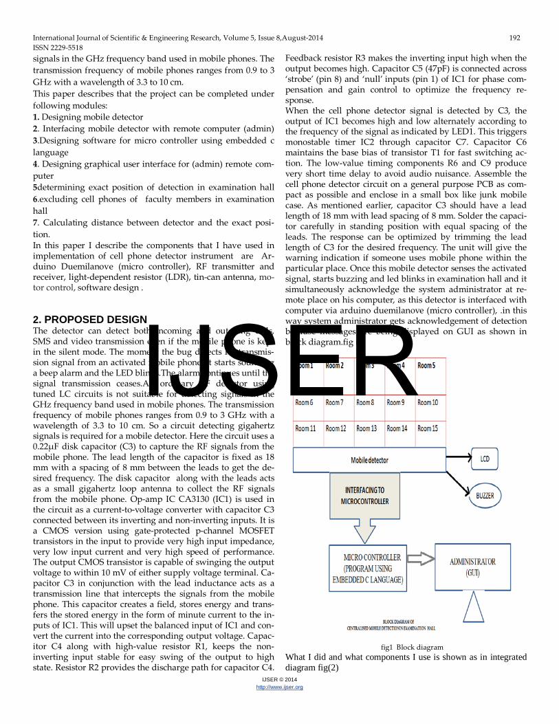
Feedback resistor R3 makes the inverting input high when the output becomes high. Capacitor C5 (47pF) is connected across ‘strobe’ (pin 8) and ‘null’ inputs (pin 1) of IC1 for phase com-pensation and gain control to optimize the frequency re-sponse. When the cell phone detector signal is detected by C3, the output of IC1 becomes high and low alternately according to the frequency of the signal as indicated by LED1. This triggers monostable timer IC2 through capacitor C7. Capacitor C6 maintains the base bias of transistor T1 for fast switching ac-tion. The low-value timing components R6 and C9 produce very short time delay to avoid audio nuisance. Assemble the cell phone detector circuit on a general purpose PCB as com-pact as possible and enclose in a small box like junk mobile case. As mentioned earlier, capacitor C3 should have a lead length of 18 mm with lead spacing of 8 mm. Solder the capaci-tor carefully in standing position with equal spacing of the leads. The response can be optimized by trimming the lead length of C3 for the desired frequency. The unit will give the warning indication if someone uses mobile phone within the particular place. Once this mobile detector senses the activated signal, starts buzzing and led blinks in examination hall and it simultaneously acknowledge the system administrator at re-mote place on his computer, as this detector is interfaced with computer via arduino duemilanove (micro controller), .in this way system administrator gets acknowledgement of detection because messages are being displayed on GUI as shown in block diagram.fig (1) fig1 Block diagram What I did and what components I use is shown as in integrated diagram fig(2)
IJSER
International Journal of Scientific & Engineering Research, Volume 5, Issue 8,August-2014 193 ISSN 2229-5518
IJSER © 2014 http://www.ijser.org
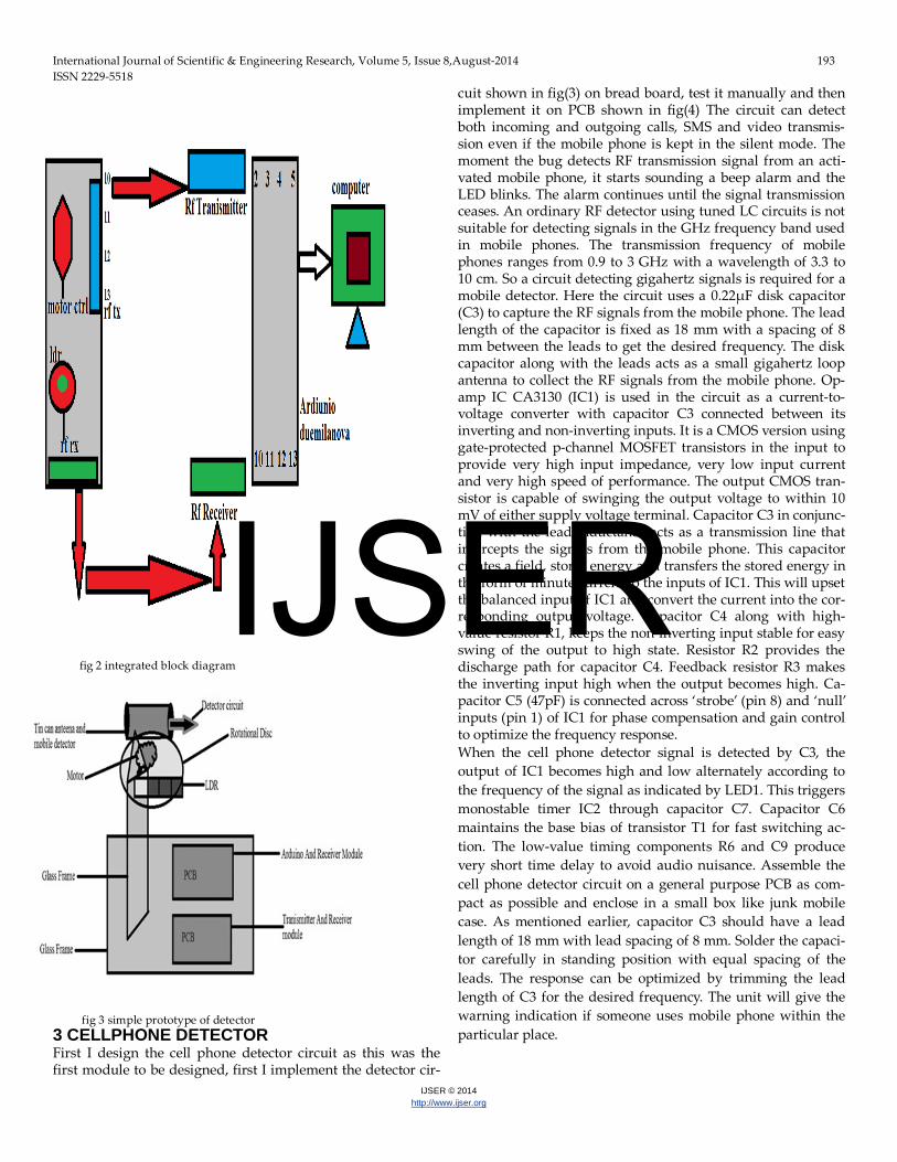
fig 2 integrated block diagram
fig 3 simple prototype of detector 3 CELLPHONE DETECTOR First I design the cell phone detector circuit as this was the first module to be designed, first I implement the detector cir-
cuit shown in fig(3) on bread board, test it manually and then implement it on PCB shown in fig(4) The circuit can detect both incoming and outgoing calls, SMS and video transmis-sion even if the mobile phone is kept in the silent mode. The moment the bug detects RF transmission signal from an acti-vated mobile phone, it starts sounding a beep alarm and the LED blinks. The alarm continues until the signal transmission ceases. An ordinary RF detector using tuned LC circuits is not suitable for detecting signals in the GHz frequency band used in mobile phones. The transmission frequency of mobile phones ranges from 0.9 to 3 GHz with a wavelength of 3.3 to 10 cm. So a circuit detecting gigahertz signals is required for a mobile detector. Here the circuit uses a 0.22μF disk capacitor (C3) to capture the RF signals from the mobile phone. The lead length of the capacitor is fixed as 18 mm with a spacing of 8 mm between the leads to get the desired frequency. The disk capacitor along with the leads acts as a small gigahertz loop antenna to collect the RF signals from the mobile phone. Op-amp IC CA3130 (IC1) is used in the circuit as a current-to-voltage converter with capacitor C3 connected between its inverting and non-inverting inputs. It is a CMOS version using gate-protected p-channel MOSFET transistors in the input to provide very high input impedance, very low input current and very high speed of performance. The output CMOS tran-sistor is capable of swinging the output voltage to within 10 mV of either supply voltage terminal. Capacitor C3 in conjunc-tion with the lead inductance acts as a transmission line that intercepts the signals from the mobile phone. This capacitor creates a field, stores energy and transfers the stored energy in the form of minute current to the inputs of IC1. This will upset the balanced input of IC1 and convert the current into the cor-responding output voltage. Capacitor C4 along with high-value resistor R1, keeps the non-inverting input stable for easy swing of the output to high state. Resistor R2 provides the discharge path for capacitor C4. Feedback resistor R3 makes the inverting input high when the output becomes high. Ca-pacitor C5 (47pF) is connected across ‘strobe’ (pin 8) and ‘null’ inputs (pin 1) of IC1 for phase compensation and gain control to optimize the frequency response. When the cell phone detector signal is detected by C3, the output of IC1 becomes high and low alternately according to the frequency of the signal as indicated by LED1. This triggers monostable timer IC2 through capacitor C7. Capacitor C6 maintains the base bias of transistor T1 for fast switching ac-tion. The low-value timing components R6 and C9 produce very short time delay to avoid audio nuisance. Assemble the cell phone detector circuit on a general purpose PCB as com-pact as possible and enclose in a small box like junk mobile case. As mentioned earlier, capacitor C3 should have a lead length of 18 mm with lead spacing of 8 mm. Solder the capaci-tor carefully in standing position with equal spacing of the leads. The response can be optimized by trimming the lead length of C3 for the desired frequency. The unit will give the warning indication if someone uses mobile phone within the particular place.
IJSER
International Journal of Scientific & Engineering Research, Volume 5, Issue 8,August-2014 194 ISSN 2229-5518
IJSER © 2014 http://www.ijser.org
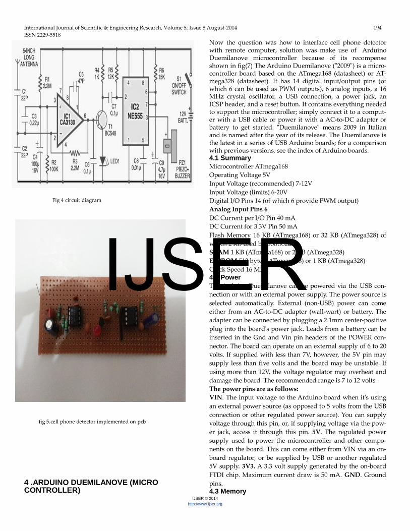
Fig 4 circuit diagram
fig 5.cell phone detector implemented on pcb 4 .ARDUINO DUEMILANOVE (MICRO CONTROLLER)
Now the question was how to interface cell phone detector with remote computer, solution was make use of Arduino Duemilanove microcontroller because of its recompense shown in fig(7) The Arduino Duemilanove ("2009") is a micro-controller board based on the ATmega168 (datasheet) or AT-mega328 (datasheet). It has 14 digital input/output pins (of which 6 can be used as PWM outputs), 6 analog inputs, a 16 MHz crystal oscillator, a USB connection, a power jack, an ICSP header, and a reset button. It contains everything needed to support the microcontroller; simply connect it to a comput-er with a USB cable or power it with a AC-to-DC adapter or battery to get started. "Duemilanove" means 2009 in Italian and is named after the year of its release. The Duemilanove is the latest in a series of USB Arduino boards; for a comparison with previous versions, see the index of Arduino boards. 4.1 Summary Microcontroller ATmega168 Operating Voltage 5V Input Voltage (recommended) 7-12V Input Voltage (limits) 6-20V Digital I/O Pins 14 (of which 6 provide PWM output) Analog Input Pins 6 DC Current per I/O Pin 40 mA DC Current for 3.3V Pin 50 mA Flash Memory 16 KB (ATmega168) or 32 KB (ATmega328) of which 2 KB used by bootloader SRAM 1 KB (ATmega168) or 2 KB (ATmega328) EEPROM 512 bytes (ATmega168) or 1 KB (ATmega328) Clock Speed 16 MHz 4.2 Power The Arduino Duemilanove can be powered via the USB con-nection or with an external power supply. The power source is selected automatically. External (non-USB) power can come either from an AC-to-DC adapter (wall-wart) or battery. The adapter can be connected by plugging a 2.1mm center-positive plug into the board's power jack. Leads from a battery can be inserted in the Gnd and Vin pin headers of the POWER con-nector. The board can operate on an external supply of 6 to 20 volts. If supplied with less than 7V, however, the 5V pin may supply less than five volts and the board may be unstable. If using more than 12V, the voltage regulator may overheat and damage the board. The recommended range is 7 to 12 volts. The power pins are as follows: VIN. The input voltage to the Arduino board when it's using an external power source (as opposed to 5 volts from the USB connection or other regulated power source). You can supply voltage through this pin, or, if supplying voltage via the pow-er jack, access it through this pin. 5V. The regulated power supply used to power the microcontroller and other compo-nents on the board. This can come either from VIN via an on-board regulator, or be supplied by USB or another regulated 5V supply. 3V3. A 3.3 volt supply generated by the on-board FTDI chip. Maximum current draw is 50 mA. GND. Ground pins. 4.3 Memory
IJSER
International Journal of Scientific & Engineering Research, Volume 5, Issue 8,August-2014 195 ISSN 2229-5518
IJSER © 2014 http://www.ijser.org
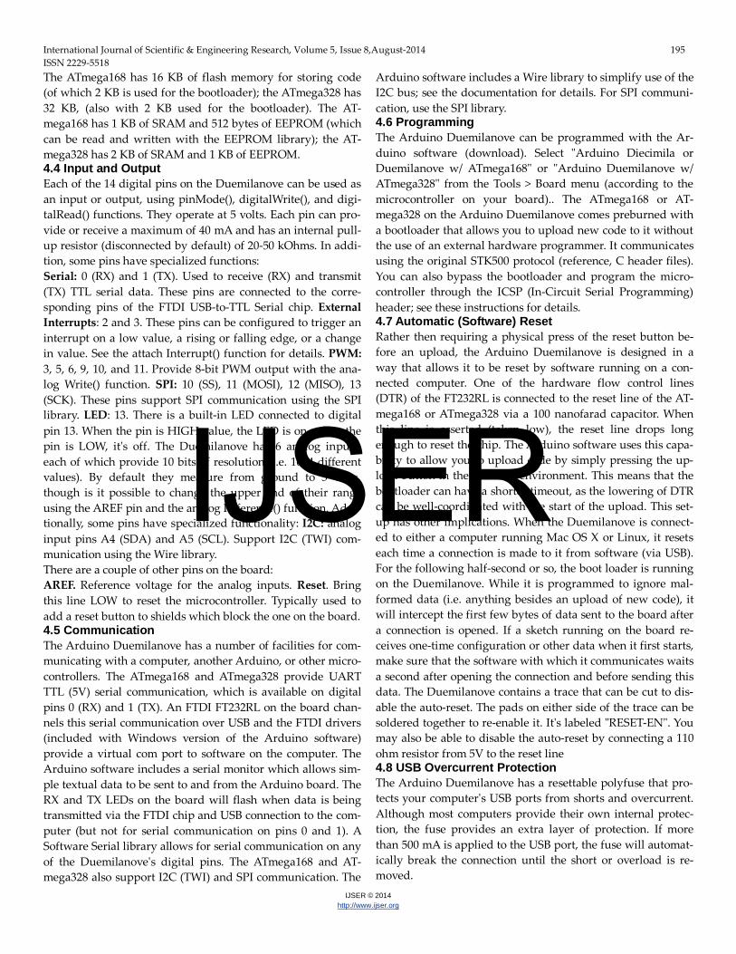
The ATmega168 has 16 KB of flash memory for storing code (of which 2 KB is used for the bootloader); the ATmega328 has 32 KB, (also with 2 KB used for the bootloader). The AT-mega168 has 1 KB of SRAM and 512 bytes of EEPROM (which can be read and written with the EEPROM library); the AT-mega328 has 2 KB of SRAM and 1 KB of EEPROM. 4.4 Input and Output Each of the 14 digital pins on the Duemilanove can be used as an input or output, using pinMode(), digitalWrite(), and digi-talRead() functions. They operate at 5 volts. Each pin can pro-vide or receive a maximum of 40 mA and has an internal pull-up resistor (disconnected by default) of 20-50 kOhms. In addi-tion, some pins have specialized functions: Serial: 0 (RX) and 1 (TX). Used to receive (RX) and transmit (TX) TTL serial data. These pins are connected to the corre-sponding pins of the FTDI USB-to-TTL Serial chip. External Interrupts: 2 and 3. These pins can be configured to trigger an interrupt on a low value, a rising or falling edge, or a change in value. See the attach Interrupt() function for details. PWM: 3, 5, 6, 9, 10, and 11. Provide 8-bit PWM output with the ana-log Write() function. SPI: 10 (SS), 11 (MOSI), 12 (MISO), 13 (SCK). These pins support SPI communication using the SPI library. LED: 13. There is a built-in LED connected to digital pin 13. When the pin is HIGH value, the LED is on, when the pin is LOW, it's off. The Duemilanove has 6 analog inputs, each of which provide 10 bits of resolution (i.e. 1024 different values). By default they measure from ground to 5 volts, though is it possible to change the upper end of their range using the AREF pin and the analog Reference() function. Addi-tionally, some pins have specialized functionality: I2C: analog input pins A4 (SDA) and A5 (SCL). Support I2C (TWI) com-munication using the Wire library. There are a couple of other pins on the board: AREF. Reference voltage for the analog inputs. Reset. Bring this line LOW to reset the microcontroller. Typically used to add a reset button to shields which block the one on the board. 4.5 Communication The Arduino Duemilanove has a number of facilities for com-municating with a computer, another Arduino, or other micro-controllers. The ATmega168 and ATmega328 provide UART TTL (5V) serial communication, which is available on digital pins 0 (RX) and 1 (TX). An FTDI FT232RL on the board chan-nels this serial communication over USB and the FTDI drivers (included with Windows version of the Arduino software) provide a virtual com port to software on the computer. The Arduino software includes a serial monitor which allows sim-ple textual data to be sent to and from the Arduino board. The RX and TX LEDs on the board will flash when data is being transmitted via the FTDI chip and USB connection to the com-puter (but not for serial communication on pins 0 and 1). A Software Serial library allows for serial communication on any of the Duemilanove's digital pins. The ATmega168 and AT-mega328 also support I2C (TWI) and SPI communication. The
Arduino software includes a Wire library to simplify use of the I2C bus; see the documentation for details. For SPI communi-cation, use the SPI library. 4.6 Programming The Arduino Duemilanove can be programmed with the Ar-duino software (download). Select "Arduino Diecimila or Duemilanove w/ ATmega168" or "Arduino Duemilanove w/ ATmega328" from the Tools > Board menu (according to the microcontroller on your board).. The ATmega168 or AT-mega328 on the Arduino Duemilanove comes preburned with a bootloader that allows you to upload new code to it without the use of an external hardware programmer. It communicates using the original STK500 protocol (reference, C header files). You can also bypass the bootloader and program the micro-controller through the ICSP (In-Circuit Serial Programming) header; see these instructions for details. 4.7 Automatic (Software) Reset Rather then requiring a physical press of the reset button be-fore an upload, the Arduino Duemilanove is designed in a way that allows it to be reset by software running on a con-nected computer. One of the hardware flow control lines (DTR) of the FT232RL is connected to the reset line of the AT-mega168 or ATmega328 via a 100 nanofarad capacitor. When this line is asserted (taken low), the reset line drops long enough to reset the chip. The Arduino software uses this capa-bility to allow you to upload code by simply pressing the up-load button in the Arduino environment. This means that the bootloader can have a shorter timeout, as the lowering of DTR can be well-coordinated with the start of the upload. This set-up has other implications. When the Duemilanove is connect-ed to either a computer running Mac OS X or Linux, it resets each time a connection is made to it from software (via USB). For the following half-second or so, the boot loader is running on the Duemilanove. While it is programmed to ignore mal-formed data (i.e. anything besides an upload of new code), it will intercept the first few bytes of data sent to the board after a connection is opened. If a sketch running on the board re-ceives one-time configuration or other data when it first starts, make sure that the software with which it communicates waits a second after opening the connection and before sending this data. The Duemilanove contains a trace that can be cut to dis-able the auto-reset. The pads on either side of the trace can be soldered together to re-enable it. It's labeled "RESET-EN". You may also be able to disable the auto-reset by connecting a 110 ohm resistor from 5V to the reset line 4.8 USB Overcurrent Protection The Arduino Duemilanove has a resettable polyfuse that pro-tects your computer's USB ports from shorts and overcurrent. Although most computers provide their own internal protec-tion, the fuse provides an extra layer of protection. If more than 500 mA is applied to the USB port, the fuse will automat-ically break the connection until the short or overload is re-moved.
IJSER
International Journal of Scientific & Engineering Research, Volume 5, Issue 8,August-2014 196 ISSN 2229-5518
IJSER © 2014 http://www.ijser.org
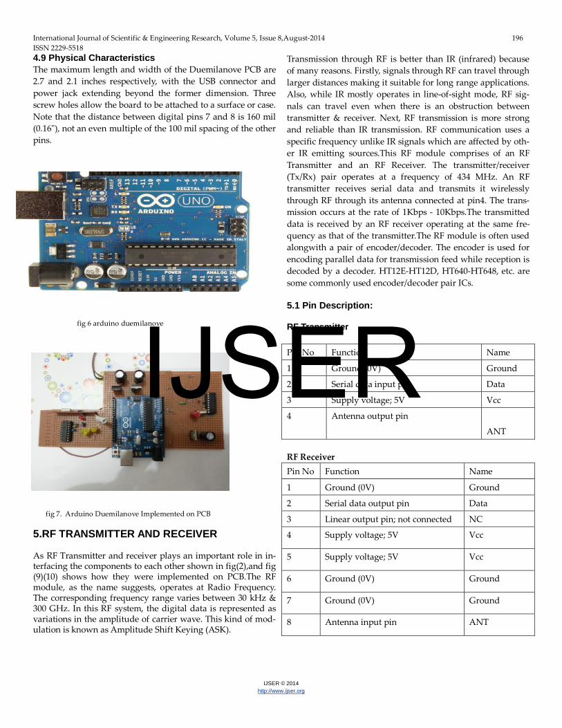
4.9 Physical Characteristics The maximum length and width of the Duemilanove PCB are 2.7 and 2.1 inches respectively, with the USB connector and power jack extending beyond the former dimension. Three screw holes allow the board to be attached to a surface or case. Note that the distance between digital pins 7 and 8 is 160 mil (0.16"), not an even multiple of the 100 mil spacing of the other pins.
fig 6 arduino duemilanove
fig 7. Arduino Duemilanove Implemented on PCB 5.RF TRANSMITTER AND RECEIVER As RF Transmitter and receiver plays an important role in in-terfacing the components to each other shown in fig(2),and fig (9)(10) shows how they were implemented on PCB.The RF module, as the name suggests, operates at Radio Frequency. The corresponding frequency range varies between 30 kHz & 300 GHz. In this RF system, the digital data is represented as variations in the amplitude of carrier wave. This kind of mod-ulation is known as Amplitude Shift Keying (ASK).
Transmission through RF is better than IR (infrared) because of many reasons. Firstly, signals through RF can travel through larger distances making it suitable for long range applications. Also, while IR mostly operates in line-of-sight mode, RF sig-nals can travel even when there is an obstruction between transmitter & receiver. Next, RF transmission is more strong and reliable than IR transmission. RF communication uses a specific frequency unlike IR signals which are affected by oth-er IR emitting sources.This RF module comprises of an RF Transmitter and an RF Receiver. The transmitter/receiver (Tx/Rx) pair operates at a frequency of 434 MHz. An RF transmitter receives serial data and transmits it wirelessly through RF through its antenna connected at pin4. The trans-mission occurs at the rate of 1Kbps - 10Kbps.The transmitted data is received by an RF receiver operating at the same fre-quency as that of the transmitter.The RF module is often used alongwith a pair of encoder/decoder. The encoder is used for encoding parallel data for transmission feed while reception is decoded by a decoder. HT12E-HT12D, HT640-HT648, etc. are some commonly used encoder/decoder pair ICs. 5.1 Pin Description: RF Transmitter Pin No Function Name
1 Ground (0V) Ground
2 Serial data input pin Data
3 Supply voltage; 5V Vcc
4 Antenna output pin
ANT RF Receiver Pin No Function Name
1 Ground (0V) Ground
2 Serial data output pin Data
3 Linear output pin; not connected NC
4 Supply voltage; 5V Vcc
5 Supply voltage; 5V Vcc
6 Ground (0V) Ground
7 Ground (0V) Ground
8 Antenna input pin ANT
IJSER

International Journal of Scientific & Engineering Research, Volume 5, Issue 8,August-2014 197 ISSN 2229-5518
IJSER © 2014 http://www.ijser.org
fig 8 RF transmitter and receiver circuit
fig 9 . RF transmitter implemented on PCB
fig 10. RF receiver implemented on PCB 6.LIGHT-DEPENDENT RESISTOR (LDR)
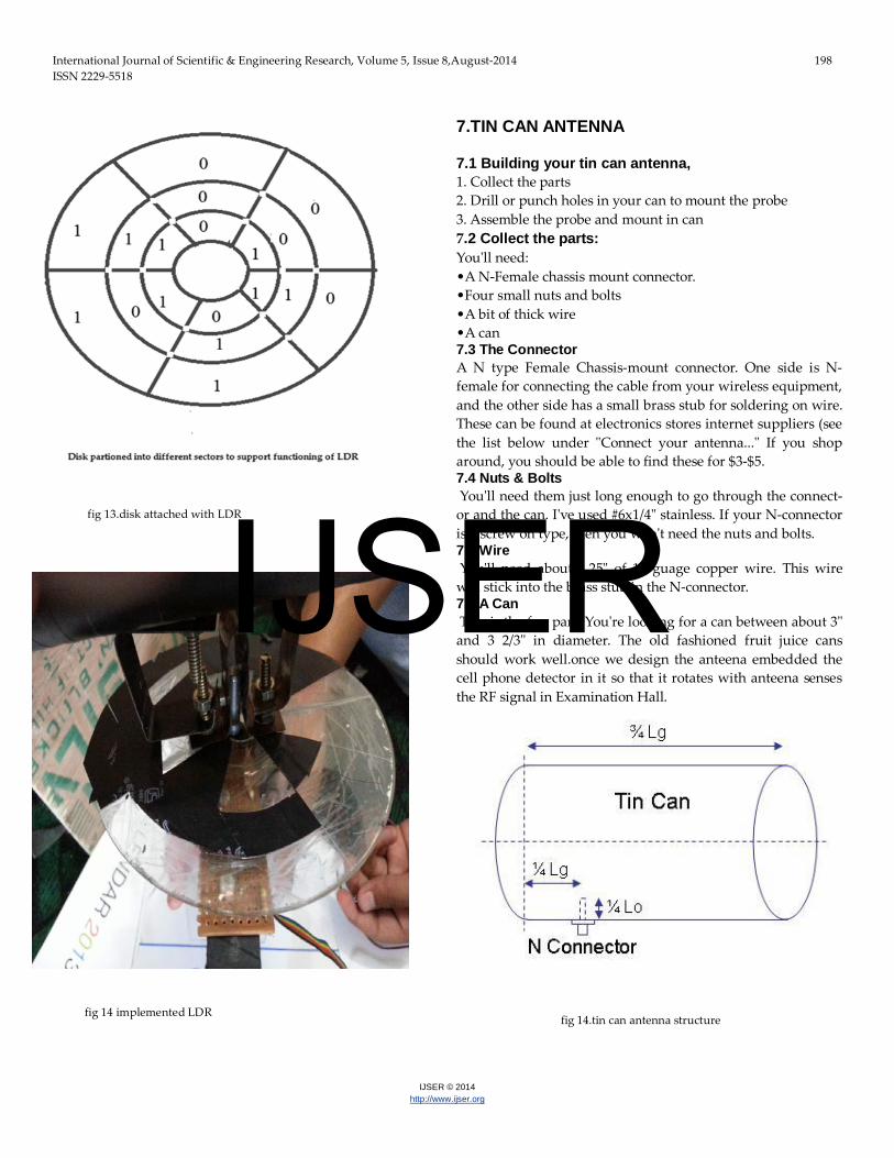
This module gives the direction to which the cell phone was detected,LDR is also interfaced with ardiunio microcontroller returns 1 and 0. A light-dependent resistor, alternatively called an LDR, photo resistor, photoconductor, or photocell, is a vari-able resistor whose value decreases with increasing incident light intensity. An LDR is made of a high-resistance semicon-ductor, often cadmium-sulfide. If light falling on the device is of high enough frequency, photons absorbed by the semiconductor give bound electrons enough energy to jump into the conduction band. The resulting free electron (and its hole partner) conduct electricity, thereby lowering resistance. A photoelectric device can be either intrinsic or extrinsic. In intrinsic devices, the only available electrons are in the valence band, and hence the photon must have enough energy texcite the electron across the entire band gap. Extrinsic devices have impurities added, which have a ground state energy closer to the conduction band - since the electrons don't have as far to jump, lower energy photons (i.e. longer wavelengths and low-er frequencies) are sufficient to trigger the device. Two of its earliest applications were as part of smoke and fire detection systems and camera light meters. Because cadmium sulfide cells are inexpensive and widely available, LDRs are still used in electronic devices that need light detection capability, such as security alarms, street lamps, and clock radios Disk is mounted above the light dependent resis-tors(LDR’s),this disk rotates along the mobile detector by mo-tor under the control of arduino duemilanove (micro control-ler).once the cell phone detector detects any wireless activity inside the examination hall, it gets stopped at that position and LDR’s return the corresponding values like 0000,0001,1111 etc ,and these values were displayed on GUI of remote com-puter.
Fig11.Light-dependentresistor
IJSER
International Journal of Scientific & Engineering Research, Volume 5, Issue 8,August-2014 198 ISSN 2229-5518
IJSER © 2014 http://www.ijser.org
fig 13.disk attached with LDR
fig 14 implemented LDR
7.TIN CAN ANTENNA 7.1 Building your tin can antenna, 1. Collect the parts 2. Drill or punch holes in your can to mount the probe 3. Assemble the probe and mount in can 7.2 Collect the parts: You'll need: •A N-Female chassis mount connector. •Four small nuts and bolts •A bit of thick wire •A can 7.3 The Connector A N type Female Chassis-mount connector. One side is N-female for connecting the cable from your wireless equipment, and the other side has a small brass stub for soldering on wire. These can be found at electronics stores internet suppliers (see the list below under "Connect your antenna..." If you shop around, you should be able to find these for $3-$5. 7.4 Nuts & Bolts You'll need them just long enough to go through the connect-or and the can. I've used #6x1/4" stainless. If your N-connector is a screw on type, then you won't need the nuts and bolts. 7.5 Wire You'll need about 1.25" of 12 guage copper wire. This wire will stick into the brass stub in the N-connector. 7.6 A Can This is the fun part. You're looking for a can between about 3" and 3 2/3" in diameter. The old fashioned fruit juice cans should work well.once we design the anteena embedded the cell phone detector in it so that it rotates with anteena senses the RF signal in Examination Hall.
fig 14.tin can antenna structure
IJSER
International Journal of Scientific & Engineering Research, Volume 5, Issue 8,August-2014 199 ISSN 2229-5518
IJSER © 2014 http://www.ijser.org
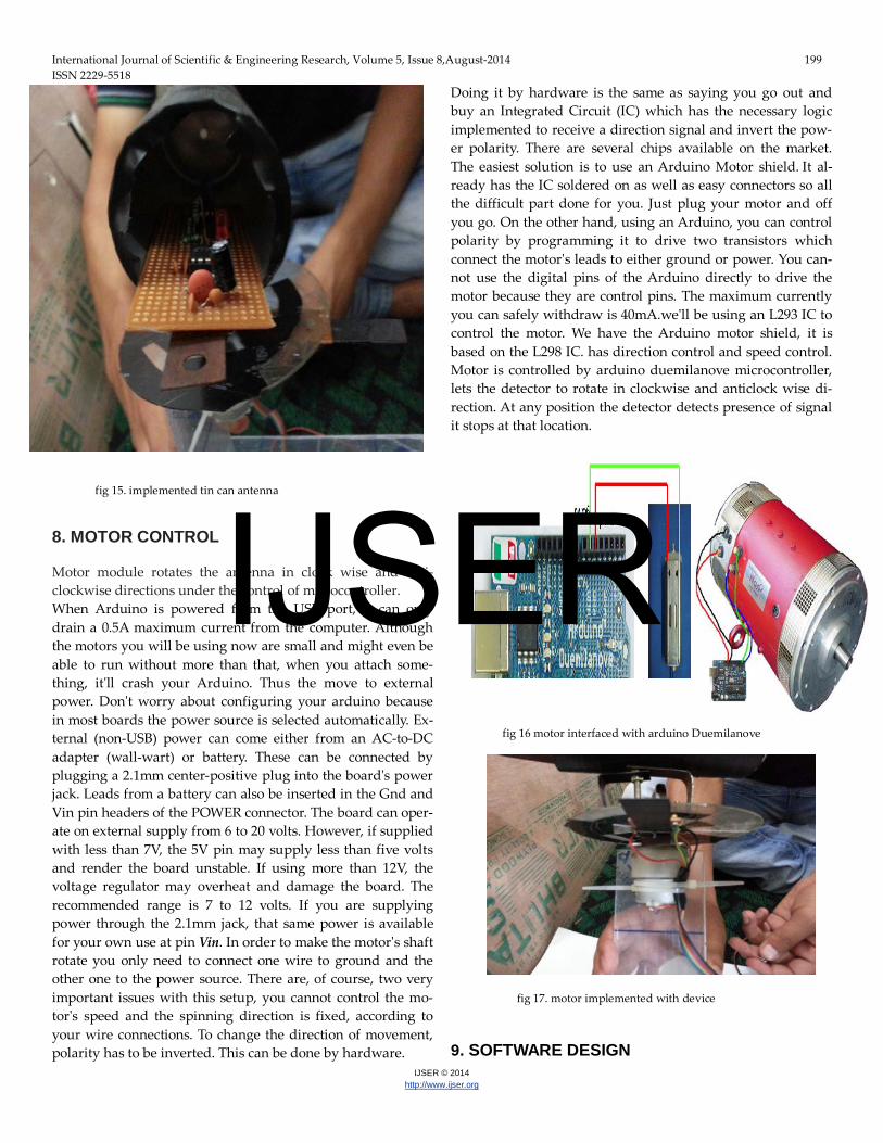
fig 15. implemented tin can antenna 8. MOTOR CONTROL Motor module rotates the antenna in clock wise and anti-clockwise directions under the control of microcontroller. When Arduino is powered from the USB port, it can only drain a 0.5A maximum current from the computer. Although the motors you will be using now are small and might even be able to run without more than that, when you attach some-thing, it'll crash your Arduino. Thus the move to external power. Don't worry about configuring your arduino because in most boards the power source is selected automatically. Ex-ternal (non-USB) power can come either from an AC-to-DC adapter (wall-wart) or battery. These can be connected by plugging a 2.1mm center-positive plug into the board's power jack. Leads from a battery can also be inserted in the Gnd and Vin pin headers of the POWER connector. The board can oper-ate on external supply from 6 to 20 volts. However, if supplied with less than 7V, the 5V pin may supply less than five volts and render the board unstable. If using more than 12V, the voltage regulator may overheat and damage the board. The recommended range is 7 to 12 volts. If you are supplying power through the 2.1mm jack, that same power is available for your own use at pin Vin. In order to make the motor's shaft rotate you only need to connect one wire to ground and the other one to the power source. There are, of course, two very important issues with this setup, you cannot control the mo-tor's speed and the spinning direction is fixed, according to your wire connections. To change the direction of movement, polarity has to be inverted. This can be done by hardware.
Doing it by hardware is the same as saying you go out and buy an Integrated Circuit (IC) which has the necessary logic implemented to receive a direction signal and invert the pow-er polarity. There are several chips available on the market. The easiest solution is to use an Arduino Motor shield. It al-ready has the IC soldered on as well as easy connectors so all the difficult part done for you. Just plug your motor and off you go. On the other hand, using an Arduino, you can control polarity by programming it to drive two transistors which connect the motor's leads to either ground or power. You can-not use the digital pins of the Arduino directly to drive the motor because they are control pins. The maximum currently you can safely withdraw is 40mA.we'll be using an L293 IC to control the motor. We have the Arduino motor shield, it is based on the L298 IC. has direction control and speed control. Motor is controlled by arduino duemilanove microcontroller, lets the detector to rotate in clockwise and anticlock wise di-rection. At any position the detector detects presence of signal it stops at that location.
fig 16 motor interfaced with arduino Duemilanove
fig 17. motor implemented with device
9. SOFTWARE DESIGN
IJSER
International Journal of Scientific & Engineering Research, Volume 5, Issue 8,August-2014 200 ISSN 2229-5518
IJSER © 2014 http://www.ijser.org
9.1 Programming The Arduino Duemilanove can be programmed with the Ar-duino software (download). Select "Arduino Diecimila or Duemilanove w/ ATmega168" or "Arduino Duemilanove w/ ATmega328" from the Tools > Board menu (according to the microcontroller on your board)..The ATmega168 or AT-mega328 on the Arduino Duemilanove comes preburned with a bootloader that allows you to upload new code to it without the use of an external hardware programmer. It communicates using the original STK500 protocol (reference, C header files). You can also bypass the boot loader and program the micro-controller through the ICSP (In-Circuit Serial Programming) header; see these instructions for details. 9.2 Automatic (Software) Reset Rather then requiring a physical press of the reset button be-fore an upload, the Arduino Duemilanove is designed in a way that allows it to be reset by software running on a con-nected computer. One of the hardware flow control lines (DTR) of the FT232RL is connected to the reset line of the AT-mega168 or ATmega328 via a 100 nanofarad capacitor. When this line is asserted (taken low), the reset line drops long enough to reset the chip. The Arduino software uses this capa-bility to allow you to upload code by simply pressing the up-load button in the Arduino environment. This means that the boot loader can have a shorter timeout, as the lowering of DTR can be well-coordinated with the start of the upload. This set-up has other implications. When the Duemilanove is connect-ed to either a computer running Mac OS X or Linux, it resets each time a connection is made to it from software (via USB). For the following half-second or so, the boot loader is running on the Duemilanove. While it is programmed to ignore mal-formed data (i.e. anything besides an upload of new code), it will intercept the first few bytes of data sent to the board after a connection is opened. If a sketch running on the board re-ceives one-time configuration or other data when it first starts, make sure that the software with which it communicates waits a second after opening the connection and before sending this data. The Duemilanove contains a trace that can be cut to dis-able the auto-reset. The pads on either side of the trace can be soldered together to re-enable it. It's labeled "RESET-EN". You may also be able to disable the auto-reset by connecting a 110 ohm resistor from 5V to the reset line; 9.3 code Constant int rx4=10; Constant int rx3=11; Constant int rx2=12; Constant int rx1=13; Constant int tx4=10; Constant int tx4=5; Constant int tx3=4;
Constant int tx2=3; Constant int tx1=2; Constant int pc 1=6; Constant int pc2=7; Constant int pc 3=8; Constant int pc4=9 int mr1=2; int mr2=3; int ml1=4; int m12=5 void setup() { pinMode (rx1, INPUT); pinMode (rx2, INPUT); pinMode (rx3, INPUT); pinMode (rx4, INPUT); pinMode (tx1, OUTPUT); pinMode (tx2, OUTPUT); pinMode (tx3,OUTPUT); pinMode (tx4, OUTPUT); pinMode (pc1, OUTPUT); pinMode (pc2, OUTPUT); pinMode (pc3, OUTPUT); pinMoSde (pc4, OUTPUT); } Void loop() { int r1=digitalRead(rx1); int r2=digitalRead(rx2); int r3=digitalRead(rx3); int r4=digitalRead(rx4); if(r4==1) { digitalWrite(tx1,LOW); digitalWrite(tx2,LOW); digitalWrite(tx3,LOW); digitalWrite(tx4,LOW); digitalWrite(pc1,r2); digitalWrite(pc2,r3); digitalWrite(pc3,r4); digitalWrite (pc4,LOW); } else { For (int i=1; i<100; i++) { digitalWrite(tx1,LOW); digitalWrite(tx2,HIGH); digitalWrite(tx3,LOW);
IJSER
International Journal of Scientific & Engineering Research, Volume 5, Issue 8,August-2014 201 ISSN 2229-5518
IJSER © 2014 http://www.ijser.org
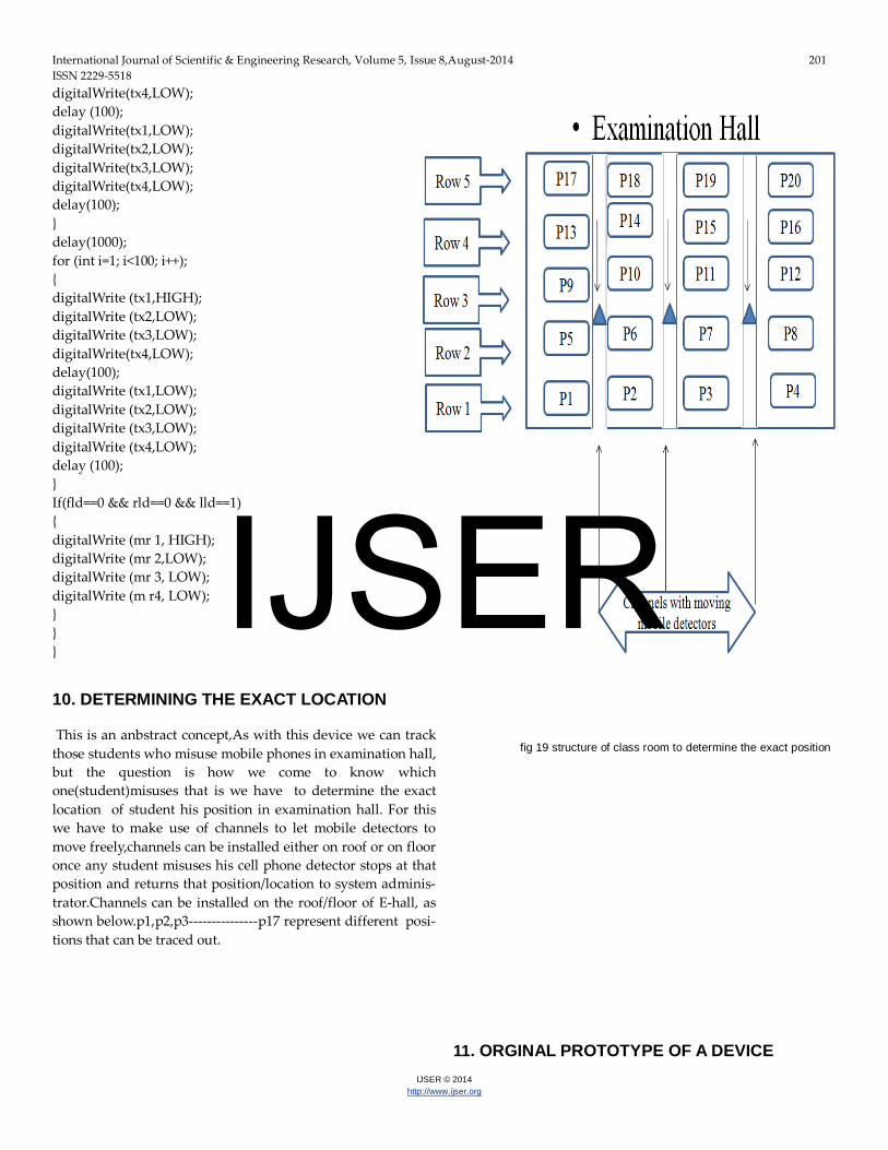
digitalWrite(tx4,LOW); delay (100); digitalWrite(tx1,LOW); digitalWrite(tx2,LOW); digitalWrite(tx3,LOW); digitalWrite(tx4,LOW); delay(100); } delay(1000); for (int i=1; i<100; i++); { digitalWrite (tx1,HIGH); digitalWrite (tx2,LOW); digitalWrite (tx3,LOW); digitalWrite(tx4,LOW); delay(100); digitalWrite (tx1,LOW); digitalWrite (tx2,LOW); digitalWrite (tx3,LOW); digitalWrite (tx4,LOW); delay (100); } If(fld==0 && rld==0 && lld==1) { digitalWrite (mr 1, HIGH); digitalWrite (mr 2,LOW); digitalWrite (mr 3, LOW); digitalWrite (m r4, LOW); } } } 10. DETERMINING THE EXACT LOCATION This is an anbstract concept,As with this device we can track those students who misuse mobile phones in examination hall, but the question is how we come to know which one(student)misuses that is we have to determine the exact location of student his position in examination hall. For this we have to make use of channels to let mobile detectors to move freely,channels can be installed either on roof or on floor once any student misuses his cell phone detector stops at that position and returns that position/location to system adminis-trator.Channels can be installed on the roof/floor of E-hall, as shown below.p1,p2,p3---------------p17 represent different posi-tions that can be traced out.
fig 19 structure of class room to determine the exact position
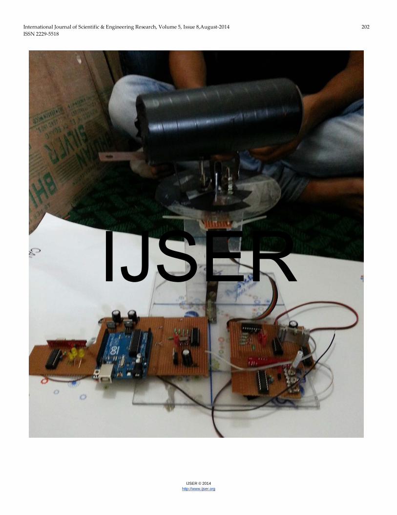
11. ORGINAL PROTOTYPE OF A DEVICE
IJSER
International Journal of Scientific & Engineering Research, Volume 5, Issue 8,August-2014 202 ISSN 2229-5518
IJSER © 2014 http://www.ijser.org
IJSER
International Journal of Scientific & Engineering Research, Volume 5, Issue 8,August-2014 203 ISSN 2229-5518
IJSER © 2014 http://www.ijser.org
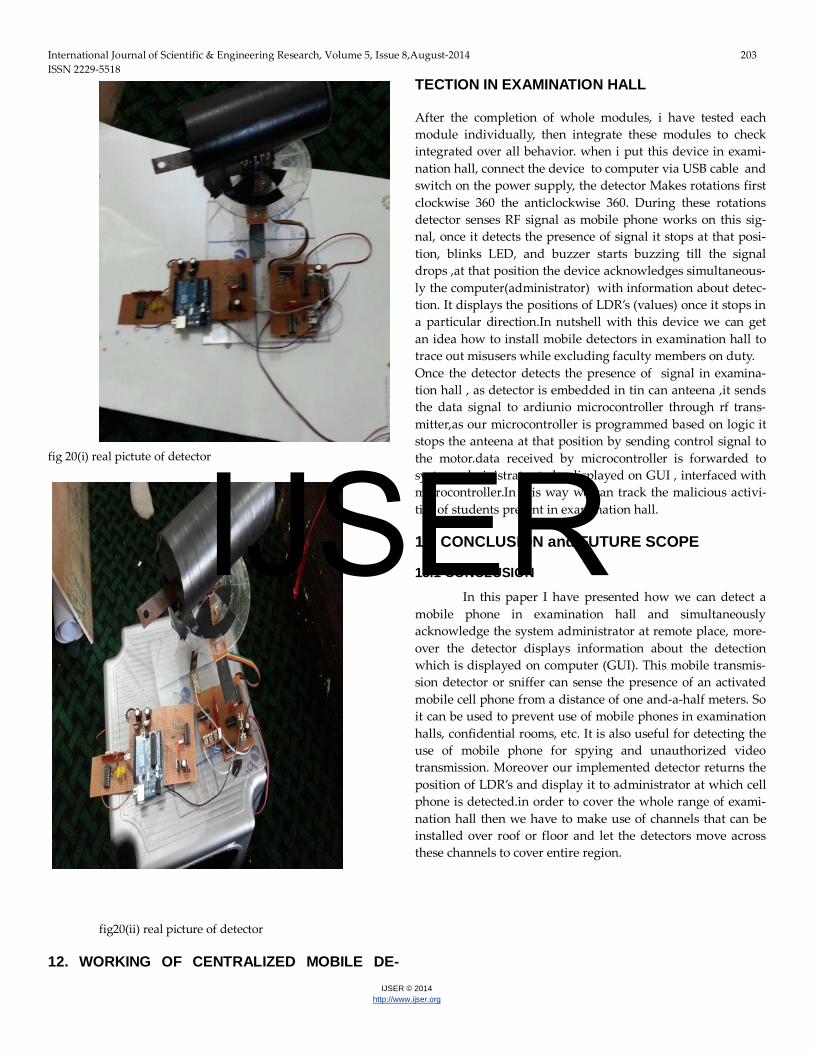
fig 20(i) real pictute of detector
fig20(ii) real picture of detector 12. WORKING OF CENTRALIZED MOBILE DE-
TECTION IN EXAMINATION HALL After the completion of whole modules, i have tested each module individually, then integrate these modules to check integrated over all behavior. when i put this device in exami-nation hall, connect the device to computer via USB cable and switch on the power supply, the detector Makes rotations first clockwise 360 the anticlockwise 360. During these rotations detector senses RF signal as mobile phone works on this sig-nal, once it detects the presence of signal it stops at that posi-tion, blinks LED, and buzzer starts buzzing till the signal drops ,at that position the device acknowledges simultaneous-ly the computer(administrator) with information about detec-tion. It displays the positions of LDR’s (values) once it stops in a particular direction.In nutshell with this device we can get an idea how to install mobile detectors in examination hall to trace out misusers while excluding faculty members on duty. Once the detector detects the presence of signal in examina-tion hall , as detector is embedded in tin can anteena ,it sends the data signal to ardiunio microcontroller through rf trans-mitter,as our microcontroller is programmed based on logic it stops the anteena at that position by sending control signal to the motor.data received by microcontroller is forwarded to system administrator to be displayed on GUI , interfaced with microcontroller.In this way we can track the malicious activi-ties of students present in examination hall. 13. CONCLUSION and FUTURE SCOPE 13.1 CONCLUSION
In this paper I have presented how we can detect a mobile phone in examination hall and simultaneously acknowledge the system administrator at remote place, more-over the detector displays information about the detection which is displayed on computer (GUI). This mobile transmis-sion detector or sniffer can sense the presence of an activated mobile cell phone from a distance of one and-a-half meters. So it can be used to prevent use of mobile phones in examination halls, confidential rooms, etc. It is also useful for detecting the use of mobile phone for spying and unauthorized video transmission. Moreover our implemented detector returns the position of LDR’s and display it to administrator at which cell phone is detected.in order to cover the whole range of exami-nation hall then we have to make use of channels that can be installed over roof or floor and let the detectors move across these channels to cover entire region.
IJSER
International Journal of Scientific & Engineering Research, Volume 5, Issue 8,August-2014 204 ISSN 2229-5518
IJSER © 2014 http://www.ijser.org
13.2 FUTURE SCOPE
We can do much research on this project based on perception of a person ,we can add new dimensions to it like, Trying to increase the detecting range of cell phone detector to few more meters for observing wide range of area. Determin-ing exact position of detection in examination hall, excluding cell phones of faculty members in examination hall so that only students can be traced out,. Calculating distance between detector and the exact position.my suggestion to readers is take onward this project as much as possible and add new dimensions to it. ACKNOWLEDGEMENT First of all I would like to thank almighty Allah(GOD), for giving me strength to complete this work.I believe that hard work is the only way to success to achieve something worthy. At the outset of this paper, I express my deep sense of grati-tude towards”Dr.Feroz Ahmad” H.O.D Electronics and Com-munication Enigineering ,Islamic university of science and technology Awantipora” Kashmir(J&K)” for allowing me the opportunity to experience dynamic professional environment and support to prepare this paper. Last but not the least, I would be thankful to all those who helped me directly or indi-rectly. Any suggestions to further improvement of this topic are most welcome.
REFERENCES [1] k.mohan dece, “novel mobile detector sensing alarming and reporting system” Arpn journal of science and technology, ISSN 2225-7217, Vol. 2, No. 1, January 2012 [2] christan c.mbaocha, “design and implementation of intel-ligent mobile phone detector” Academic Research Interna-tional, ISSN-L: 2223-9553, ISSN: 2223-9944 Vol. 3, No. 1, July 2012 [3] Mobile Phone Sniffer track down mobile phones using this handy directional finder Design by B. Kainka. [4] Applying Packets Sniffer by Ghossoon. M. W. Al-Saadoon College of Administrative Sciences, Applied Science Ass. Prof. Manager Center of D&R for Lecturer Staff , University, King-dom of Bahrain ,Manama. [5] Abdul K.A, Asa’d Nalm, Ahmed Hassan, Ayman Samier, (2008). Mobile phone intelligent jamming system. Jordan. Ahmed, J. (2006). “GSM 900 mobile jammer”, Undergrad project, JUST. [6] Ahmed, S.A., Ahmed N.R.M. (2006).” Dual band mobile jammer for GSM900andBSM1800”.Jordan.
[7] Mazda, Fraidoon. (1993). Telecommunication Engineers Ref-erence Book. 1st Ed. London: Butterworth Heinemann, [8] Mohan Kumar, D. (2008). “Mobile Bug”. Electronics for you magazine.
IJSER