Embed Size (px)
Citation preview

BANK OF OKLAHOMA (BOK) CENTER – TULSA, OK
Presented by: Darren Hartman, P.E. Thornton Tomasetti March 4, 2009

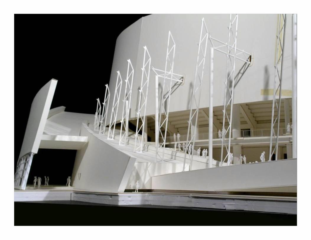
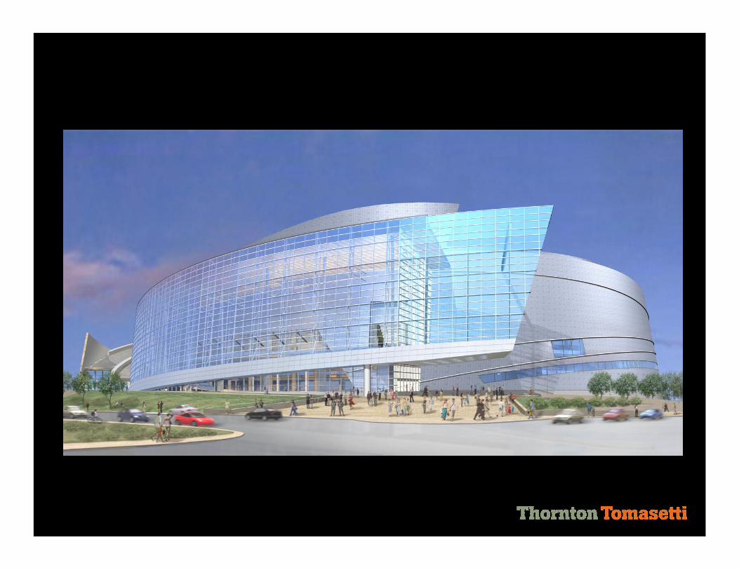
Bank of Oklahoma Center During Conception

Bank of Oklahoma Center Upon Completion
Photo Courtesy of Gayle Babcock – Architectural Imageworks, LLC
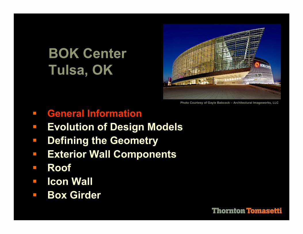
BOK Center Tulsa, OK
§ General Information § Evolution of Design Models § Defining the Geometry § Exterior Wall Components § Roof § Icon Wall § Box Girder
Photo Courtesy of Gayle Babcock – Architectural Imageworks, LLC
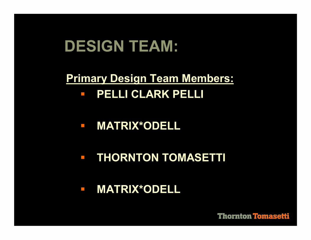
Primary Design Team Members: § PELLI CLARK PELLI
§ MATRIX*ODELL
§ THORNTON TOMASETTI
§ MATRIX*ODELL
DESIGN TEAM:

Tulsa Vision Builders: § Joint Venture between Flintco and
Manhattan
§ Construction Manager for fee and Owners rep
CONSTRUCTION TEAM:

Cost: § $178 Million Construction Cost
ARENA SPECIFICS:
Schedule: § Design Fall 2004 thru Jan 2006 § Ground Breaking August 2005 § Grand Opening August 2008

Square Footage and Capacity: § 600,000 Square Feet § Basketball – 17,620 seats § Hockey – 16,800 seats § Center Stage Concert – 17,600 seats § End Stage Concert – 13,700 seats
ARENA SPECIFICS:

BOK Center Tulsa, OK
§ General Information § Evolution of Design Models § Defining the Geometry § Exterior Wall Components § Roof § Icon Wall § Box Girder
Photo Courtesy of Gayle Babcock – Architectural Imageworks, LLC


Integration of Software: § Rhino used by Design Architects to
define building envelope § ADT used for production drawings § Tekla Structures used for steel
definition and coordination between trades
DESIGN INTEGRATION TOOLS:

Integration of Software: § Rhino § ADT § Tekla Structures § SAP § RISA
DESIGN INTEGRATION TOOLS:

BOK Center Tulsa, OK
§ General Information § Evolution of Design Models § Defining the Geometry § Exterior Wall Components § Roof § Icon Wall § Box Girder
Photo Courtesy of Gayle Babcock – Architectural Imageworks, LLC

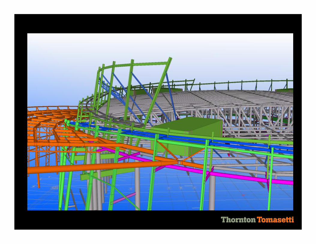
Geometry Plans: § Bowl Geometry Plan § Exterior Wall Geometry Plan – 6
distinct workpoints with varying radii, sloped in elevation, curved in plan (truncated cones)
§ Icon Wall Geometry
GEOMETRY DEFINITION:

Multiple Geometry Plans: § Bowl Geometry Plan § Exterior Wall Geometry Plan
– 6 distinct workpoints (forming truncated cones)
§ Icon Wall Geometry
COMPLEX GEOMETRY :


BOK Center Tulsa, OK
§ General Information § Evolution of Design Models § Defining the Geometry § Exterior Wall Components § Roof § Icon Wall § Box Girder
Photo Courtesy of Gayle Babcock – Architectural Imageworks, LLC

Structural System: § Structural steel columns –
slope 10 degrees from vertical
§ Exterior columns have thrust and bending requiring special design considerations
EXTERIOR WALLS:

§ Exterior Wall Framing Elevation


Selection of a Cladding System: § Stickbuilt metal stud system vs.
panelized system by Zahner
§ Schedule, erectibility concerns, interior finishes, and cladding
EXTERIOR FACADE:


BOK Center Tulsa, OK
§ General Information § Evolution of Design Models § Defining the Geometry § Exterior Wall Components § Roof § Icon Wall § Box Girder
Photo Courtesy of Gayle Babcock – Architectural Imageworks, LLC

Selection of an Optimum Roof System: § Stiff and light § Easy erection and quick erection
stability § Design flexibility for support of hung
loads and parapet braces
ARENA ROOF:
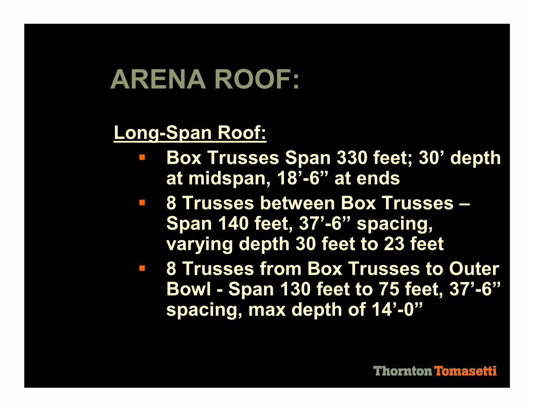
LongSpan Roof: § Box Trusses Span 330 feet; 30’ depth
at midspan, 18’6” at ends § 8 Trusses between Box Trusses –
Span 140 feet, 37’6” spacing, varying depth 30 feet to 23 feet
§ 8 Trusses from Box Trusses to Outer Bowl Span 130 feet to 75 feet, 37’6” spacing, max depth of 14’0”
ARENA ROOF:

Box Trusses
Infill Trusses

Box Trusses
Center Infill Trusses
Outer Infill Trusses
ARENA ROOF SECTION


§ 10 degree truncated cones cantilever 40 feet above main roof level
§ Braced in the plane of the wall by a continuous strut
§ Braced out of plane by diagonals connected to the high roof
Upper Parapet Walls:

§ Need .pdf of Detail 1 S324
BOK Center Tulsa, OK
§ General Information § Evolution of Design Models § Defining the Geometry § Exterior Wall Components § Roof § Icon Wall § Box Girder
Photo Courtesy of Gayle Babcock – Architectural Imageworks, LLC

§ 500 foot long architecturally exposed steel system and curtainwall
§ Vertical pipe trusses spaced at 24’ oc, 4’8” deep, spans up to 76 feet
§ Horizontal pipe trusses at 48’ oc to support the roof
§ Box beam 100’ backspan, 80’ cantilever
Icon Wall:


§ Icon Wall Framing Elevation


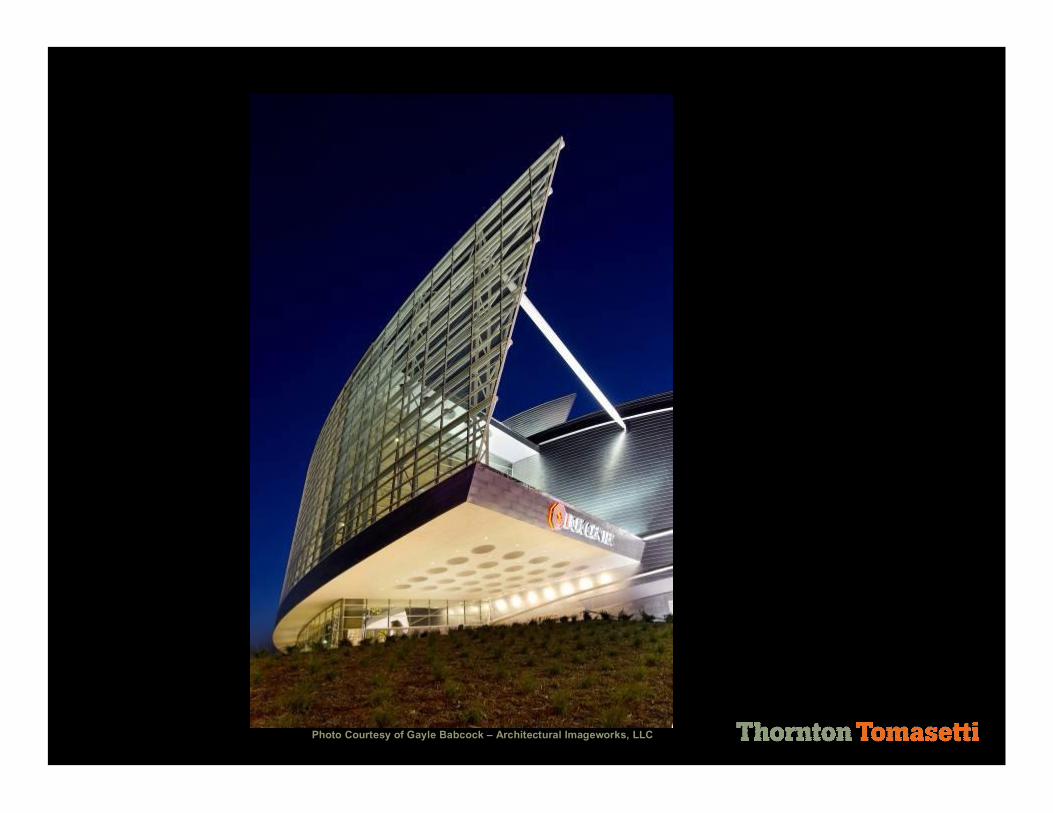
Photo Courtesy of Gayle Babcock – Architectural Imageworks, LLC


§ Designed for 110 mph 3second gust § Horizontal girts transfer load to vert. truss § Vertical truss takes load down to box
girder and up to Icon Wall roof § Icon Wall roof drags the force back to the
main structure and into the MWFRS § 30” dia pipe strut tranfers all load at the
end of the Icon Wall back to the structure
Icon Wall – Lateral Loads:

WIND
P w
P w P G P G
P G


BOK Center Tulsa, OK
§ General Information § Evolution of Design Models § Defining the Geometry § Exterior Wall Components § Roof § Icon Wall § Box Girder
Photo Courtesy of Gayle Babcock – Architectural Imageworks, LLC
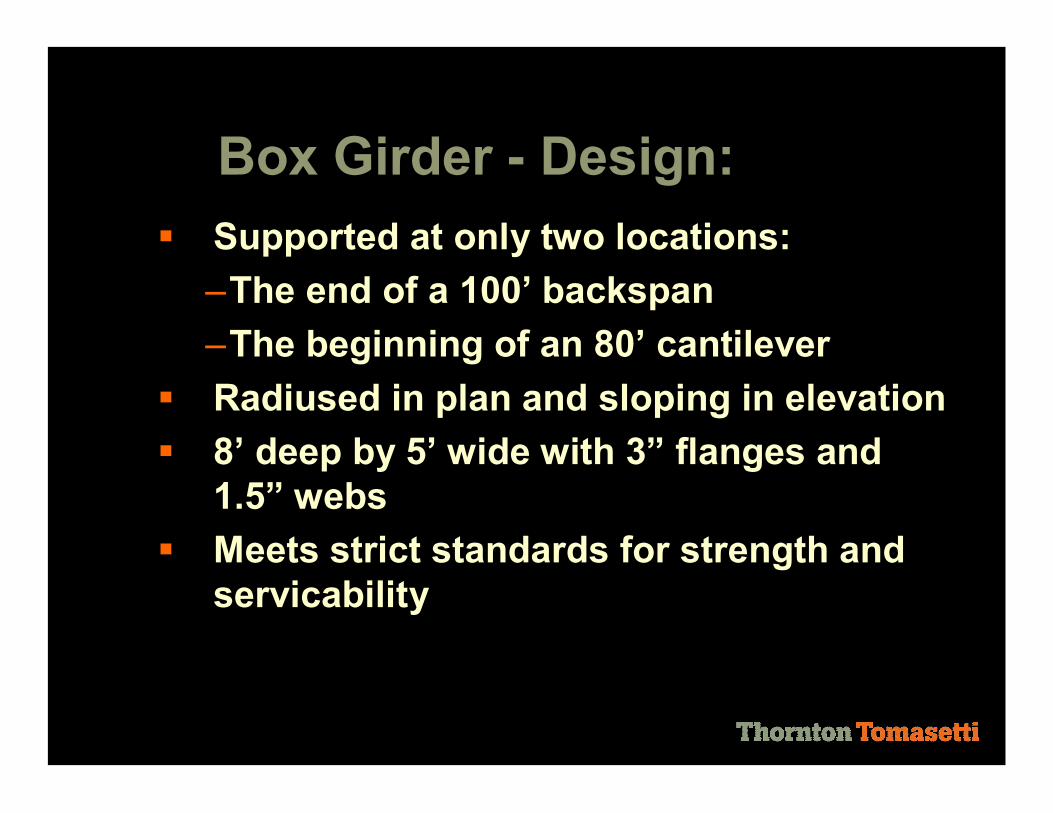
§ Supported at only two locations: –The end of a 100’ backspan –The beginning of an 80’ cantilever
§ Radiused in plan and sloping in elevation § 8’ deep by 5’ wide with 3” flanges and
1.5” webs § Meets strict standards for strength and
servicability
Box Girder Design:


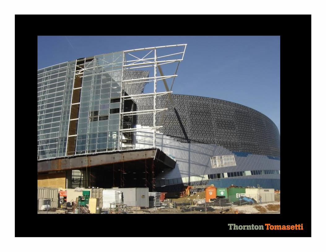
§ Shop fabricated in ~25’ segments with camber
§ Lifted into place, shored, and field welded § After verifying proper placement, shores
were removed § Tie down forces were applied to replicate
the asbuilt dead loads § Glass curtain wall was constructed § Tie downs were slowly released
Box Girder – Construction:


§ Don’t delete slide after this one – if you double click on it, it becomes a 2 minute video of the arena.


Photo Courtesy of Gayle Babcock – Architectural Imageworks, LLC

Thank you Darren R. Hartman, P.E. 912 Broadway Boulevard, Suite 100 Kansas City, MO 64105 T 816.221.7771 F 816.221.7787