Embed Size (px)
Citation preview
1
CENTER-ROLL DIVIDER CURTAIN No.’s 2081, 2082, 2084, 2085
Installation, Operation, and Maintenance Manual
© 2012 PORTER ATHLETIC, INC. ALL RIGHTS RESERVED
INST00316030 07-15-2013

2
INSTRUCTIONS: Dealer and/or Installation Supervisor,
Please give this book to the Owner/Customer
NAME OF PROJECT:
NAME OF DEALER: NAME OF INSTALLATION COMPANY:
PHONE #: PHONE #:
Porter Order Number _________________________
Date of Scheduled Shipment _________________________
Date of Substantial Completion _________________________
The gymnasium equipment for this project has been custom fabricated according to the
Owner’s/Architect’s specification. Care has been taken to fabricate and install this
equipment to provide years of safe, satisfactory use and trouble free service.
The key to satisfactory service is proper operation and care. Should any malfunctions
occur, please notify your supervisor and call your local Porter Dealer or Representative.

3
TABLE OF CONTENTS
WARRANTY INFORMATION ................................................................. 4-5 MANUAL OVERVIEW ............................................................................... 6 OPERATIONAL INSTRUCTIONS ............................................................. 8 MAINTENANCE AND INSPECTION CHECKLIST ............................... 9-12 INVENTORY AND TOOLS ...................................................................... 13 INSTALLATION INSTRUCTIONS ...................................................... 14-24 ELECTRICAL FIELD WIRING ............................................................ 25-34
DUAL MOTOR SPECIAL NOTE: These installation instructions are for single and dual motor opera-tion only with either a wall guide or torque belt arm operation. Steps that are specific to the torque belt arm installation appear in the highlighted (shaded) areas. The dual motor curtain requires drive-train components at each end to properly raise and lower the curtain. To avoid being redundant, the dual motor installation instructions will describe a detailed installation procedure at one end of the curtain only. Installation at the opposite end of the curtain will typically be the same as the first end. For this reason, the instructions for the second drive system will not be as detailed, and will typically state “repeat installation procedure at the opposite end of the curtain".

4
PORTER LIMITED PRODUCT WARRANTY Product Line: 2080 Center-roll Curtain (the “Equipment”) Porter Athletic (“Porter”) provides the below limited warranty (the “Limited Warranty”) to the original purchaser of the Equipment and only as to the facility in which the Equipment was originally installed. The Limited Warranty extends from the time the Equipment is installed by qualified installers and continues based on the timeline listed below under the terms and conditions stated below. Limited Warranty Terms and Conditions Porter warrants the Equipment against defects in material or factory workmanship which cause failure of the Equipment within the applica-ble Limited Warranty period and provided that notification of defects, together with proof of purchase, is given to Porter at [email protected] within thirty (30) days of discovery of such defect. Porter, once it confirms the existence of a covered defect will, at its sole discretion, repair or replace the defective Equipment with comparable Equipment or will provide a refund of the purchase price pro-rated over the remaining Limited Warranty period. In the event of repair or replacement, the Limited Warranty includes labor, materials, and freight during the first year of the Limited Warranty and then materials only for the balance of the Limited Warranty period based on the Limited Warranty coverage time period shown below for each category. All other costs, expenses or losses are excluded, including, but not limited to, costs for maintenance of the Equipment. The manner of fulfillment of the Limited Warranty (including investigation, timing of response, labor, and manner of shipment, if applicable) is at the sole discretion of Porter. Standard Limited Warranty Coverage Time Period 1 year - Structural Components, Mechanical Components, Electrical Components, Fabric Other components—may be covered by separate warranty, please see product information sheets Exclusions and Conditions: This limited warranty excludes and does not apply to: Damage, whether natural or manmade, including, but not limited to fire, flood, wind, lightening or other acts of nature or God. Normal maintenance items such as fuses and belts. Normal wear and tear Use for other than intended purpose or use not in accord with generally approved practices Abuse, neglect, vandalism, alterations, modifications or misuse – as determined by Porter Equipment not installed by Porter Athletic Approved Installers Natural variations occurring in product finishes are not considered defects. User attached accessories Damage caused by operation of Equipment by persons not properly trained to operate it Equipment not routinely inspected and maintained by facility personnel or operators in accordance with the Porter Operation and Maintenance Manual. In cases where repair or replacement of Equipment is deemed necessary, color or texture shall be in accord with that offered by Porter at the then current time. Porter’s liability under this Limited Warranty is limited to repair or replacement of defective Equipment or a prorated refund as described above. The sole and exclusive remedy against Porter, or its parent, affiliates, subsidiaries, or distributors shall be for the repair, replacement or prorated refund, at Porter’s sole discretion, of any defective Equipment as provided herein. IN NO EVENT SHALL PORTER OR ITS PARENT, AFFILIATES, SUBSIDIARIES, OR DISTRIBUTORS BE LIABLE FOR ANY INCIDENTAL OR CONSEQUENTIAL DAMAGES RELATING TO, ARISING OUT OF OR IN CONNEC-TION WITH THE USE OR PERFORMANCE OF THE EQUIPMENT, INCLUDING WITHOUT LIMITTION, ANY LABOR AND /OR OTHER IN-STALLATION EXPENSES INCURRED IN CONNECTION WITH THE REPLACEMENT OR REPAIR OF DEFECTIVE EQUIPMENT, EXCEPT TO THE EXTENT OTHERWISE SET FORTH HEREIN, OR ANY OTHER INDIRECT OR CONSEQUENTIAL DAMAGES OF ANY NATURE WHATSO-EVER, INCLUDING, BUT NOT LIMITED TO, LOSS OF REVENUE, PROFITS OR OPPORTUNITY.
This document constitutes Porter’s Limited Warranty in its entirety and no other provisions express or implied exist. This Limited Warranty excludes, with-out limitation, any implied warranties of merchantability or fitness for a particular purpose. Any modifications of this Limited Warranty must be in writing and signed by an officer of Porter. No other person, agent or representative of Porter or any distributor or dealer has any authority to change or modify this Limited Warranty, either verbally or in writing. Porter reserves the right to change required inspection and maintenance provisions for the Equipment from time to time and upon notification of such change, Customer must abide by those revised provisions or this limited warranty is void. Various states may have laws affecting your rights under this Limited Warranty.

5
PORTER EXTENDED LIMITED PRODUCT WARRANTY Product Line: 2080 Center-roll Curtain (the “Equipment”) Porter Athletic (“Porter”) provides the below extended limited warranty (the “Extended Limited Warranty”) to the original purchaser of the Equipment and only as to the facility in which the Equipment was originally installed. The Extended Limited Warranty extends from the time the Equipment is installed by qualified installers and continues based on the timeline listed below under the terms and conditions stated below, including, but not limited to, the required inspections and maintenance referenced below (the “Maintenance Program”). Extended Limited Warranty Terms and Conditions Porter warrants the Equipment against defects in material or factory workmanship which cause failure of the Equipment within the applica-ble Extended Limited Warranty period and provided that notification of defects, together with proof of purchase, is given to Porter at [email protected] within thirty (30) days of discovery of such defect. Porter, once it confirms the existence of a covered defect and compliance with the Maintenance Program, will, at its sole discretion, repair or replace the defective Equipment with comparable Equipment or will provide a refund of the purchase price prorated over the remaining Extended Limited Warranty period. In the event of repair or re-placement, the Extended Limited Warranty includes labor, materials, and freight during the first year of the Extended Limited Warranty and then materials only for the balance of the applicable Extended Limited Warranty based on the Extended Limited Warranty coverage time period shown below for each category. All other costs, expenses or losses are excluded, including, but not limited to, costs for maintenance of the Equipment. The manner of fulfillment of the Extended Limited Warranty (including investigation, timing of response, labor, and man-ner of shipment, if applicable) is at the sole discretion of Porter. Extended Limited Warranty Coverage Time Period 15 years – Structural Components (Structure Pipes, and Ceiling attachments) 10 years – Mechanical Components (Center Tubes, Torque Arm Straps, Saf-Straps) 5 years -- Electrical Components (Motors, Control Systems) Other components – Covered by separate warranty, please see product information sheets Exclusions and Conditions: This Extended Limited Warranty excludes and does not apply to Equipment not properly inspected or maintained by a Porter certified inspector at least annually in accordance with the Maintenance Program set forth in the current Porter Installation, Operation and Maintenance Manual for Basketball Backstops of the series covering the involved Equipment which is delivered with the product, is available on line at www.porterathletic.com, or which may be ordered from Por-ter. Damage, whether natural or manmade, including, but not limited to fire, flood, wind, lightening or other acts of nature or God. Normal maintenance items such as fuses and belts. Normal wear and tear Use for other than intended purpose or use not in accord with generally approved practices Abuse, neglect, vandalism, alterations, modifications or misuse – as determined by Porter Equipment not installed by Porter Athletic Approved Installers Natural variations occurring in product finishes are not considered defects. User attached accessories Damage caused by operation of Equipment by persons not properly trained to operate it Equipment not routinely inspected and maintained by facility personnel or operators in accordance with the Porter Operation and Maintenance Manual. In cases where repair or replacement of Equipment is deemed necessary, color or texture shall be in accord with that offered by Porter at the then current time. Porter’s liability under this Extended Limited Warranty is limited to repair or replacement of defective Equipment or a prorated refund as described above. The sole and exclusive remedy against Porter, or its parent, affiliates subsidiaries, or distributors shall be for the repair, replacement or prorated refund, at Porter’s sole discretion, of any defective Equipment as provided herein. IN NO EVENT SHALL PORTER OR ITS PARENT, AFFILIATES, SUBSIDIAR-IES, OR DISTRIBUTORS BE LIABLE FOR ANY INCIDENTAL OR CONSEQUENTIAL DAMAGES RELATING TO, ARISING OUT OF OR IN CONNECTION WITH THE USE OR PERFORMANCE OF THE EQUIPMENT, INCLUDING WITHOUT LIMITTION, ANY LABOR AND /OR OTH-ER INSTALLATION EXPENSES INCURRED IN CONNECTION WITH THE REPLACEMENT OR REPAIR OF DEFECTIVE EQUIPMENT, EX-CEPT TO THE EXTENT OTHERWISE SET FORTH HEREIN, OR ANY OTHER INDIRECT OR CONSEQUENTIAL DAMAGES OF ANY NATURE WHATSOEVER, INCLUDING, BUT NOT LIMITED TO, LOSS OF REVENUE, PROFITS OR OPPORTUNITY. This document constitutes Porter’s Extended Limited Warranty in its entirety and no other provisions express or implied exist. This Extended Limited War-ranty excludes, without limitation, any implied warranties of merchantability or fitness for a particular purpose. Any modifications of this Extended Limited Warranty must be in writing and signed by an officer of Porter. No other person, agent or representative of Porter or any distributor or dealer has any author-ity to change or modify this Extended Limited Warranty, either verbally or in writing. Porter reserves the right to change required inspection and maintenance provisions for the Equipment from time to time and upon notification of such change, Customer must abide by those revised provisions or this Extended Limited Warranty is void. Various states may have laws affecting your rights under this Extended Limited Warranty.

6
MODEL No. 2080 CENTER-ROLL® DIVIDER CURTAINS OVERVIEW OF MANUAL
This manual has been prepared to assist you with the installation, operation and maintenance of the No. 2080 Center-Roll® Divider Curtains. Enclosed in this manual is an inspection list for your equipment, including operational information. We recommend that you read this manual to become familiar with the operation of the No. 2080 Center-Roll® Divider Curtains, and then assign it to the person responsible for the maintenance and inspection program. If you need additional copies of this manual, please let us know. The safest equipment can be damaged when used by the untrained. We suggest that qualified personnel supervise all utilized equipment. For ease of administering this maintenance program, we suggest that your equipment be numbered, and a file maintained on its location, name of manufacturer, original item number, date of purchase, and maintenance performed. This will be useful when ordering replacement parts and keeping track of maintenance. Defective equipment must be marked "DO NOT USE", and the circuit breaker must be turned off and also tagged "DO NOT USE", until replacement or repairs are completed. Inspections should be performed periodically, depending upon the nature of the equipment and its use. When the equipment is exposed to heavy use, special inspections should be made in addition to the normal maintenance program. At the minimum, a yearly inspection of the system is recommended. Any structural and/or electrical deviation from the Porter installation manuals and drawings, without written authorization, will void all warranties.
WARNING
READ ALL INSTRUCTIONS THOROUGHLY BEFORE ATTEMPTING TO OPERATE THIS EQUIPMENT. FAILURE TO COMPLY WITH THE FOLLOWING INSTRUCTIONS AND WARNINGS MAY RESULT IN SERIOUS INJURIES AND/OR PROPERTY DAMAGE.

7
LIABILITY
Liability is not only an issue with the installation and maintenance of this product, but it also extends to the proper operation by the end user. The operational instructions must be read and understood before operating this equipment! This manual for the model No. 2080 Center-Roll Divider Curtains, which provides explicit examples of a variation of overhead attachments, is meant to serve as a general guideline only, for the safe installation of this product. Variables must be taken into consideration which are outside of Porter's control, including, but not limited to, steel joist variations which include splice plate interference, web panel point attachments if specified by the architect, conduit interference, HVAC and sprinkler interference, non-grouted cells of block walls, spacing and frequency of wall ties, appropriate selection of wall anchors for the given wall composition, proper installation of said anchors, embed depth of the anchors, etc. It is Porter's explicit requirement that this product be installed in a safe and secure manner. Any structural deviation from Porter installation drawings without written authorization will void all warranties. Contact the factory immediately should such a condition exist, necessitating a design revision. All anchor and fastening methodology is to comply with the International Conference of Building Officials (ICBO), the Uniform Building Code (UBC), the Industrial Fastener Institute (IFI), and all state regulatory agencies, such as The Division of the State Architect (DSA) in California.
General Hardware Guidelines
Do not substitute hardware without written authorization from the factory.
Minimum Grade 5 hardware is to be utilized at all attachments, unless specified otherwise. Refer to the specific part drawing in this manual for the proper grade of hardware.
On eyebolt applications, a turned eye is not acceptable. Utilize forged eyebolts or, if necessary, a turned eye that is welded closed.
Do not substitute for the factory-supplied cable and cable clamps. The quality of the 1/8" cable and clamps can vary widely from different manufacturers, and are not all suited for curtain applications.
All “S” hook connections must be crimped closed.
All Nicopress® clamps must be installed utilizing the proper tool and technique listed in this manual, ensuring a “worn” tool is NOT used. Nicopress® clamps must be copper. Never use aluminum clamps.

8
MODEL NO. 2080 CENTER ROLL DIVIDER CURTAIN OPERATIONAL INSTRUCTIONS
The Model No. 2080 Center-Roll® divider curtain is powered by a 110-volt electric torque motor assembly, which develops forces. This equipment is only to be operated by qualified personnel to avoid structural damage or possible injury to the operator and other individuals in the gymnasium. Caution should be exerted at all times for safety reasons, keeping the following guidelines in mind: ONLY authorized, TRAINED personnel are to operate the 2080 Divider Curtain. Authorized
personnel is defined as an individual (or individuals) who is at least 21 years of age, has witnessed the proper operation of the unit, and is sanctioned by the facility as being responsible for the operation of the divider curtain.
The key switch or Powr-Touch® pad, which controls the divider curtain, must be flush mounted
on the wall, located in full view of the operator, and not directly beneath the equipment. Always make sure the area below the divider curtain and in the path of travel is clear of all
individuals when raising and lowering the unit. The divider curtain may be raised or lowered by placing the “UP” OR “DOWN” key into the key
switch, and turning as indicated on the switch cover plate. Refer to the separate Powr-Touch® manual for the key pad type operation.
The key that operates the unit should be retained at all times by a designated authorized person,
or kept in a lock box. Make sure that the key is never left in the key switch unattended! It is critical the operator visually monitor the area around the curtain through the entire raising
and lowering travel cycles, making certain no one is at or near the curtain travel. Pay particular attention to the unit as it nears a limit switch cut-off juncture. If the limits are not stopping the curtain at the “DOWN” position with minimal cable slack, or allowing the curtain to raise higher than the top of the curtain fabric, contact your Porter representative immediately.
Again the safest equipment can be damaged when used by the untrained. It is imperative the procedures set forth in this manual are strictly observed. Note: The key switch must be labeled with the following operational instructions, as shown. If your key switch is not labeled properly, contact your Porter dealer immediately.
WARNING
ENTRAPMENT OR EQUIPMENT FAILURE.

9
MODEL NO. 2080 MAINTENANCE CHECK LIST
Porter recommends a maintenance inspection take place at least once a year by a Porter Certified Inspector, using the attached check list. Porter recommends the same check list be used as a guide for additional inspections by facility personnel or operators every 6 months. Any abnormal movement or sound during operation is cause for an immediate and thorough inspection. The annual inspection by a Porter Certified Inspector is required to maintain the extended limited warranty.
1. GENERAL Before inspecting, be certain to follow all OSHA guidelines concerning the use of scaffolds and lifts. The proximity of the scaffold or lift to the curtain must be of adequate distance to provide working clearance, so as not to have the curtain contact the lift during operational checks. Make certain the Porter key switch, Powr-Touch® pad, or control system are not substituted and is located within full view (but not beneath) the divider curtain. Check the walls in close proximity to the curtain for any type of protrusion that may interfere with the raising or lowering of the unit (i.e., new scoreboard, chinning bars, etc.).
2. TORQUE MOTOR ASSEMBLY
The electric torque motor is permanently lubricated, maintenance free and designed for long life. The torque motor itself does not require any type of scheduled inspection. However, the electric cord or other attached components should be inspected periodically for proper alignment, damage, or wear.
3. WALL GUIDE TRACK AND BRACKET ASSEMBLY (NO. 2081 AND 2084)
Annually inspect the wall guide track and bracket assembly. Inspect the guide track for rigid attachment to wall, and ensuring that all mounting bolts are tight. Check the wall bracket assembly rollers for excessive wear and hardware for tightness. In addition, check the spring clamp ring for positive motor attachment.
4. TORQUE ARM ASSEMBLY (NO. 2082 AND 2085)
Visually inspect the torque arm belt edges for excessive fabric wear, fraying, or cuts. Observe the operation of the torque arm. Ensure the assembly operates smoothly, and that the belt is centered on guide roller the entire duration of its operation. Lubricate the torque arm bearings annually with a high temperature bearing grease, or when audible signs of operation indicate a need for lubrication. In addition, check the spring clamp ring for positive motor attachment. Ensure the strap travels vertically above the arm and is free of damage, kinks, or wrinkles.
5. RETRACTABLE CORD REEL ASSEMBLY The cord reel assembly must be visually inspected annually, paying particular attention to the retracting cords integrity. Inspect the outer jacket of the cords for cuts, abrasion marks, or other signs of damage. Also, check the electrical connectors for tightness. Ensure the connector tightly grips the cord. If any problems are noted, replace the suspected components immediately. Failure to replace damaged electrical components could lead to an electrical short causing damage to equipment and injury to others.

10
6. CENTER-ROLL®
BATTEN TUBE
All splice locations and rivet fasteners are to be inspected for structural integrity. Ensure the splices are tight with no noticeable free play between the batten tubes. Inspect each splice rivet for a tight secure connection and for flush fit with batten tube. In addition, carefully inspect the rivets securing the motor drive to the batten tube, also checking that the rivets are tight with no free play or protrusions.
7. UPPER AND LOWER CURTAIN SUPPORT TUBES Inspect both upper and lower support tubes (inside curtain pockets), ensuring that the tubes are in line and not separating at the splice locations. Ensure that the lower support tube is secured to the bottom pocket at each end. Make sure the screws are in place and that the tube is approximately flush with the fabric edge at each end. A pipe cap should also be in place at each end of the lower support tube to prevent damage to the curtain fabric.
8. SUPERSTRUCTURE Visually inspect all super structure and connections for any sign of abnormal deflection or structural cracks. Check all hardware to confirm it is present and secure.
9. TOP TUBE SUPPORTS Check that the top tube of the curtain has all of the supports still attached and secure. Ensure all connections are closed and that the top tube is still level. Adjust as necessary.
10. CURTAIN FABRIC Inspect the curtain for any tears or holes in the fabric. Additional fabric can be obtained through Porter Athletic, to be used for patching. Industrial vinyl cement will easily bond the vinyl patch to the curtain. Also, check the fabric for signs of tearing or loosening at the seams. Check grommets at all pull�up lines. The fabric may be cleaned with a mild solution of soap cleaner and water, or Power Foam sold by Rigmar Industries of Elk Grove Village, Illinois (1-800-323-0779).

11
2080 DIVIDER CURTAIN INSPECTION REPORT
The following page should be copied and returned to Porter Athletic by a Porter Certified Inspector after each inspection.
Porter Order Number _________________________
Project Name _________________________
Name of Selling Dealer _________________________
Date of Scheduled Shipment _________________________
Date of Substantial Completion _________________________
(Information should be found on the first page of Installation manual)
Inspecting Company Name ___________________________________________
Porter Certified Inspector Name ____________________________________________
Inspection Date ____________________________________________
Summary of Inspected Equipment, Include any replaced, repaired, damaged, or worn
parts.___________________________________________________________________
_______________________________________________________________________
_______________________________________________________________________
_______________________________________________________________________
_______________________________________________________________________
_______________________________________________________________________
_______________________________________________________________________
_______________________________________________________________________
_______________________________________________________________________
_______________________________________________________________________
_______________________________________________________________________
_______________________________________________________________________
_______________________________________________________________________
Please attach the checklist of each equipment inspected
12
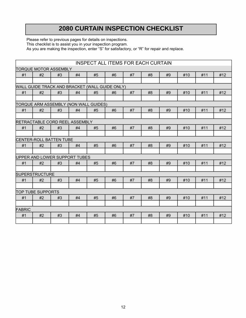
2080 CURTAIN INSPECTION CHECKLIST
Please refer to previous pages for details on inspections. This checklist is to assist you in your inspection program. As you are making the inspection, enter “S” for satisfactory, or “R” for repair and replace.
INSPECT ALL ITEMS FOR EACH CURTAIN TORQUE MOTOR ASSEMBLY
#1 #2 #3 #4 #5 #6 #7 #8 #9 #10 #11 #12
WALL GUIDE TRACK AND BRACKET (WALL GUIDE ONLY)
#1 #2 #3 #4 #5 #6 #7 #8 #9 #10 #11 #12
TORQUE ARM ASSEMBLY (NON WALL GUIDES)
#1 #2 #3 #4 #5 #6 #7 #8 #9 #10 #11 #12
RETRACTABLE CORD REEL ASSEMBLY
#1 #2 #3 #4 #5 #6 #7 #8 #9 #10 #11 #12
CENTER-ROLL BATTEN TUBE
#1 #2 #3 #4 #5 #6 #7 #8 #9 #10 #11 #12
UPPER AND LOWER SUPPORT TUBES
#1 #2 #3 #4 #5 #6 #7 #8 #9 #10 #11 #12
SUPERSTRUCTURE
#1 #2 #3 #4 #5 #6 #7 #8 #9 #10 #11 #12
TOP TUBE SUPPORTS
#1 #2 #3 #4 #5 #6 #7 #8 #9 #10 #11 #12
FABRIC
#1 #2 #3 #4 #5 #6 #7 #8 #9 #10 #11 #12

13
INVENTORY AND INSPECTION
Inventory parts listed on the packing list to ensure parts required are accounted for. Inspect all
components for possible shipping damage. Report any shortages to Porter’s Customer Service
Department immediately. On visible freight damage, sign as damaged, and file a freight damage
claim with the carrier immediately. Failure to report shortages or hidden freight damage directly to
Porter’s Customer Service Department within three working days will place the financial burden for
the missing or replacement parts with the installer or general contractor.
PREPARATION OF ASSEMBLY AREA
Moving the curtain after assembly is both difficult and awkward. For that reason, the assembly of the
curtain should take place below or near the curtain overhead support location. The floor should be
protected with a suitable material, covering the entire length of the curtain in the assembly area to
prevent damage to the floor or curtain. In addition, the floor and the covering must be free of any
debris generated from assembly procedures prior to fabric installation.
TOOLS / EQUIPMENT REQUIRED
To Be Provided by the Installer:
Pop Rivet Gun
Scissors
Wire Fish Tape
Electric Drill
13/64” Dia. Drill Bit
1/2” Dia. Countersink Bit
Standard Tool Set
DUAL MOTOR SPECIAL NOTE: These installation instructions are for single and dual motor operation only with either a wall guide or torque belt arm operation. Steps that are specific to the torque belt arm installation appear in the highlighted (shaded) areas. The dual motor curtain requires drive-train components at each end to properly raise and lower the curtain. To avoid being redundant, the dual motor installation instructions will describe a detailed installation procedure at one end of the curtain only. Installation at the opposite end of the curtain will typically be the same as the first end. For this reason, the instructions for the second drive system will not be as detailed, and will typically state “repeat installation procedure at the opposite end of the curtain".

6
2. PREPARATION OF ASSEMBLY AREA
Moving the curtain after assembly is both difficult and awkward. For that reason, the assembly of the curtain should take place below or
near the curtain overhead support location. The floor should be protected with a suitable covering the entire length of the curtain in the
assembly area to prevent damage to the floor or curtain. In addition, the floor and the covering must be free of any debris generated from
assembly procedures prior to fabric panel installation.
3. BATTEN TUBE ASSEMBLY
Begin by referring to the installation drawing for the batten tube section dimensions/layout. Assemble batten tubes per dimensions
utilizing the 2’-10” lg. splice tube at each connection location. A total of twelve (12) pop rivets are used to connect the batten tubes at each
splice location. Begin assembly, by inserting splice tube 1’-5” into batten tube end. Drill one (1) 13/64” dia. hole as shown in Figure A.
Countersink the hole to sufficiently recess the pop rivet head. Install one (1) pop rivet. Drill the remaining five (5) holes as dimensioned.
Install five (5) pop rivets. Repeat procedure for the other end of the splice at that location, and at the other batten tube connection
locations.
FIGURE A Batten Tube with Splice Tube Inserted Connecting Batten Tubes at Splice Location
BATTEN TUBE END VIEW
POP RIVET/SPLICE DETAIL
1'-5" 1'-5"
8 1/2"
1'-0" 2 1/2"
DRILLING LOCATION
GROOVES
DRILLING LOCATION
GROOVES
2'-10" LG. SPLICE TUBE
DRILLING LOCATION
GROOVES
BATTEN TUBE
POP RIVET
ALTERNATE RIVET QUANTITY AT
EACH GROOVE. SPACE RIVETS
ACCORDINGLY PER DETAIL ABOVE.
TWO RIVETS
ONE RIVET
ONE RIVET
TWO RIVETS

7
4. BATTEN TUBE INSPECTION
Inspect batten tube cable slots for metal shavings that may have accumulated in the batten tube cable slot. Remove all shavings or other
debris from the slots and other areas of the batten tube. At this time, double-check all pop rivets for protrusions and connection locations
for alignment and smoothness. All rough edges or protrusions must be removed, or they will leave indentations or cuts in the fabric.
Verify the batten tube length by referencing the installation drawing dimension, trim excess length if required.
5. FABRIC INSTALLATION
Fabric installation requires a minimum of two people for installing the upper and lower curtain panels to the batten tube - One person to
pull the panel through the cord slot, and the other person to help guide the panel into the cord slot. If pulling the panel requires more than
a moderate amount of force, a solution of soap and water can be applied to the panel cord pocket to reduce the friction. This solution is
best applied to the panel as it is pulled through the cord slot and/or applied into the batten tube cord slot. In addition, care must be
exercised at the batten tube splice locations. The curtain panel must slide freely at all the splice joints. If the curtain panel snags at a
splice, correct the problem before proceeding further.
Determine the best location for fabric installation. Install one fabric panel at a time. Lay down the accordion folded fabric panel with the
panel’s cord pocket parallel to the cable slot at one end of the batten tube. Typically, the extruded cord is longer than the curtain panel.
Do not cut the cord to size until after the panel is pulled through the cord slot. Begin by sliding the panel cord into the batten tube’s cord
slot. See Figure B. Continue pulling the panel completely into/through the cord slot until the curtain panel edge is near the opposite end of
the batten tube. Refer to the installation drawing for edge of curtain to end of batten tube reference dimensions. At this time, cut the panel
cord flush with the end of the batten tube. Hint: Slide panel slightly in each direction to facilitate cutting the cord. Ensure that the cord
does not protrude from the end of the batten tube. Repeat for other fabric panel.
Preparing Fabric Panel for Installation Sliding Fabric Panel into Batten Tube Cable Slot
FIGURE B
6. PREPARING UPPER SUPPORT TUBE POCKET
Refer to the installation drawing for anchor point spacing. Mark curtain upper support tube pocket at each anchor point. Using scissors or
a utility knife, make semi-circle cutouts at each point. See cutout detail below.
Cutout Detail
2"
4"
UPPER SUPPORT
TUBE
TYPICAL UPPER PANEL
POCKET CUTOUTPIPE HANGER

8
7. SUPPORT TUBE ASSEMBLY
Refer to installation drawing for upper support tube length. Determine if space permits the upper support tube to be pre-assembled prior to
installation in the curtain pocket. Otherwise, the support tubes should be assembled one section at a time as they are pushed through the
curtain pocket. The instructions below assume the support tubes can be assembled outside the curtain pocket, and slid in afterwards as a
unit.
Refer to the installation drawing for dimension/details on upper support tubes. Start upper support tube assembly by inserting the swaged
end of first tube completely into the plain end of the second tube. Drill two (2) 13/64” dia. holes and secure the connection with two (2)
pop rivets. See Fig. C. Repeat the above steps for the other connections. After assembly, simply slide the end of the assembled support
tube into the upper curtain panel pocket. To facilitate the installation, slip the curtain support hanger assemblies around the upper support
as the tube slides past each upper pocket cutout. If necessary, cut the end of the tube assembly per the installation drawing, after the upper
support tube assembly is installed in the curtain pocket.
The lower support tube assembly can be installed in the curtain lower pocket before or after the curtain is suspended. Installing the support
tube assembly before the curtain is raised will increase the effort required to raise the curtain to the support structure. For this reason, if
space allows, it is advised that the lower support tube be installed after the curtain is suspended.
The lower support tube is assembled in the same manner as the upper support tube, with the exception of the weighted end sections. The
weighted end sections must be positioned at each motor end for torque arm installations only. Note: Wall guide installations do not
require a weight system. In addition, the weighted sections must not be altered. They must remain as full uncut sections. Only the
intermediate support tubes can be cut. Thus, the complete length (same length as curtain) of the support tube assembly must be calculated
before the tubes can be installed. After assembly, simply slide the support tube assembly into the lower curtain panel pocket. Secure the
tube to the lower pocket at each end with bolt. See pocket detail below.
FIGURE C
Lower Pocket Detail
DETAIL "I"3/16" DIA. POP RIVET
3/16" DIA. POP RIVETPLAIN END OF
SUPPORT TUBE
DETAIL "K"
1 5/16" DIA.
PIPE CAP LOWER SUPPORT
TUBE
GROMMET
LOWER PANEL
LOWER CURTAIN
PANEL
INSTALLER NOTE: SECURE TUBE TO
LOWER POCKET WITH SELF DRILLING,
SELF TAPPING SCREW AS SHOWN.
9
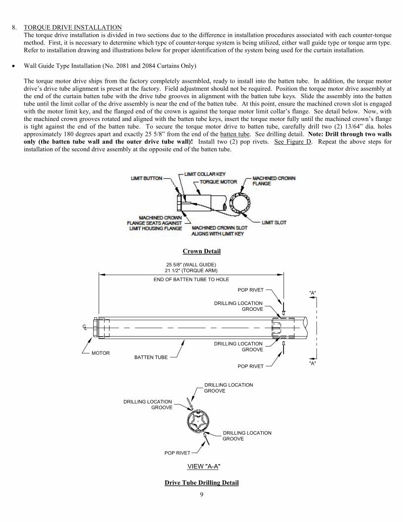
8. TORQUE DRIVE INSTALLATION
The torque drive installation is divided in two sections due to the difference in installation procedures associated with each counter-torque
method. First, it is necessary to determine which type of counter-torque system is being utilized, either wall guide type or torque arm type.
Refer to installation drawing and illustrations below for proper identification of the system being used for the curtain installation.
� Wall Guide Type Installation (No. 2081 and 2084 Curtains Only)
The torque motor drive ships from the factory completely assembled, ready to install into the batten tube. In addition, the torque motor
drive’s drive tube alignment is preset at the factory. Field adjustment should not be required. Position the torque motor drive assembly at
the end of the curtain batten tube with the drive tube grooves in alignment with the batten tube keys. Slide the assembly into the batten
tube until the limit collar of the drive assembly is near the end of the batten tube. At this point, ensure the machined crown slot is engaged
with the motor limit key, and the flanged end of the crown is against the torque motor limit collar’s flange. See detail below. Now, with
the machined crown grooves rotated and aligned with the batten tube keys, insert the torque motor fully until the machined crown’s flange
is tight against the end of the batten tube. To secure the torque motor drive to batten tube, carefully drill two (2) 13/64” dia. holes
approximately 180 degrees apart and exactly 25 5/8” from the end of the batten tube. See drilling detail. Note: Drill through two walls
only (the batten tube wall and the outer drive tube wall)! Install two (2) pop rivets. See Figure D. Repeat the above steps for
installation of the second drive assembly at the opposite end of the batten tube.
Crown Detail
Drive Tube Drilling Detail
LIMIT SLOT
LIMIT BUTTON
MACHINED CROWN
FLANGE SEATS AGAINST
LIMIT HOUSING FLANGE MACHINED CROWN SLOT
ALIGNS WITH LIMIT KEY
MACHINED CROWN
FLANGETORQUE MOTOR
LIMIT COLLAR KEY
LC
"A"
"A"
25 5/8" (WALL GUIDE)
21 1/2" (TORQUE ARM)
END OF BATTEN TUBE TO HOLE
POP RIVET
DRILLING LOCATION
GROOVE
DRILLING LOCATION
GROOVE
POP RIVET
MOTORBATTEN TUBE
DRILLING LOCATION
GROOVE
POP RIVET
DRILLING LOCATION
GROOVE
DRILLING LOCATION
GROOVE
VIEW "A-A"

10
Machined Crown Installed on Motor Motor with Drive Tube Installed Torque Motor Installed in Batten Tube
FIGURE D
� Torque Arm Type Installation (No. 2082 and 2085 Curtains Only)
Torque arm drive assembly installation can be performed after the curtain is suspended, but if space limitations do not provide adequate
clearance when the curtain is suspended, the torque arm drive assembly must be installed prior to hanging the curtain. Regardless of when
the installation takes place, the installation procedure is identical. The instructions below cover the entire torque arm drive installation
procedure. The installer must determine when the torque arm drive installation is to take place.
Before proceeding with the assembly and installation of the torque arm drive assembly; refer to the installation drawing for mounting
location and torque arm cantilever orientation. Note: The torque arms must cantilever in the same direction! The torque arm drive
ships from the factory completely assembled, ready to install into the batten tube, with the exception of the torque arm strap. The strap is
not routed through the spacers and not dead wrapped on the torque arm drum at the factory. These steps must be performed later. In
addition, the torque drive’s drive tube alignment is preset at the factory. Field adjustment should not be required. To install the torque arm
drive into the batten tube, align the drive tube grooves with the mating keys of the batten tube. Gradually insert the assembly into the
batten tube. While pushing the assembly into the batten tube, ensure the torque arm sleeve grooves are aligned with the batten tube keys.
Push the torque arm drive into the batten tube until the assembly is fully seated against the batten tube end. To secure torque motor drive
to batten tube, carefully drill two (2) 13/64” dia. holes approximately 180 degrees apart and 21 1/2” from the end of the batten tube. See
drilling detail on Page 9. Note: Drill through two walls only (the batten tube wall and the outer drive tube wall)! Install two (2) pop
rivets. See Figure E. Repeat the above steps for installation of the second motor assembly at the opposite end of the batten tube.
Typical Torque Arm Drive Assembly
FIGURE E

11
9. TORQUE MOTOR EXTENSION CORD
A custom extension cord with a pre-wired 4-prong plug at one end, and plain (cut) end at the other (requires field wiring) is provided with
each dual motor curtain. The cord is required to connect the motor synchronizer unit to the cord reel assembly at the opposite end of the
curtain. The cord is installed in the curtain upper support tube with the 4-prong plug located at motor synchronizer end of the curtain.
Refer to motor synchronizer section for the mounting location. Prior to hoisting the curtain to the overhead structure, use a wire fish tape
to pull the plain end of the extension cord through the upper support tube. Note: Ensure the pre-wired 4-prong plug is located at the
synchronizer end of the curtain. Pull the cord through the tube slowly and carefully without snagging the cord at the splice points. After
pulling the cord through the upper support tube, allow the extra cord length to hang from the end of the upper support tube. Do not cut the
cord at this time. The cord should be cut and connector terminated after the curtain is hanging from the support structure. Allow adequate
cord length for proper connection to the cord reel plug. Refer to the wiring diagram at the back of this manual to terminate the wires to the
connector properly.
8. WALL GUIDE TRACK INSTALLATION (No. 2081 and 2084 Curtains Only)
Note: The following instructions assume that the wall surface is plumb, and free of protrusions, or defects. In addition, the wall
must be capable of withstanding the lateral forces generated by the curtain operation.
Refer to installation drawing for wall guide track mounting location. Wall guide tracks should be installed prior to hanging the curtain.
The wall guide track centerline is based on curtain centerline. Referencing the curtain centerline, mark the wall at the proposed top of
track location (typically the attachment height of the curtain). Refer to the installation drawing for the bottom of track location. Then,
using the top of track mark on the wall, suspend a plumb bob to mark wall for the bottom of track location. Anchor the track to the wall
with 3/8" diameter (minimum) hardware, and appropriate anchors (not provided). Refer to recommended anchor spacing illustration
below. Repeat above steps for track at opposite end of the curtain.
For installations that require more than one section of wall guide track, it is necessary that the track sections mate perfectly (without
misalignment). Failure to align wall guide track sections properly can lead to curtain operation malfunction
Wall Guide Track Detail
11. HOISTING AND ANCHORING THE CURTAIN
Depending on anchoring conditions, it may be necessary to install supplemental support hardware to existing structure prior to raising the
curtain. Refer to the installation drawing for details.
WALL GUIDE TRACK ANCHORED
TO WALL WITH SUITABLE ANCHORS
(ANCHORS PROVIDED BY OTHERS)
TYPICAL C.M.U. WALL
"A"
LOCATE WALL ANCHORS
PER WALL SECTION DETAIL
(ANCHORS BY OTHERS).
TR
AC
K L
EN
GT
H (
SE
E I
NS
TA
LL
AT
ION
DR
AW
ING
)
4'-0
"± O
.C. M
AX
IMU
M A
NC
HO
R S
PA
CIN
G
3"
SEE INSTALLATION
DRAWING
BOTTOM OF TRACK
TOP OF TRACK
"A"SEE INSTALLATION
DRAWING
3"
3/8" DIA. ANCHORS RECOMMENDED.
HOLES TO BE DRILLED IN FIELD. THE
FACE OF TRACK IS DESIGNED WITH
A CONTINUOUS GROOVE FOR DRILLING.
TORQUE BRACKET SLOT
WALL GUIDE TRACK
SECTION "A-A"

12
The recommended method of raising the curtain to the support structure is by utilizing the Porter No. 02080-INS installation kit. The kit
consists of a set of rope, pulleys, clamps and rope ratchet mechanisms. The kit provides a block and tackle type mechanical advantage,
along with a ratchet type lock to prevent the curtain from falling while it is being raised. Start raising the curtain slowly and evenly,
continue raising the curtain until the upper support tube hangers can be attached to the support steel. Anchor the curtain with the provided
hangers and hardware. Make adjustments as required to level the curtain properly. Refer to the installation drawing for reference
dimensions. See Figure F
FIGURE F
Rope Hoist Rigging Detail
CURTAIN UPPER
SUPPORT TUBE
ROPE RATCHET
ASSEMBLY
PULLEY
PIPE CLAMP
ROPE & RATCHET ATTACH
TO OVERHEAD SUPPORT
3/8" DIA. ROPE
PULL-UP END
OF ROPE

13
12. TORQUE MOTOR SYNCHRONIZER PANEL (Dual Motor Curtains Only)
A motor synchronizer unit is provided with all dual motor curtains. The unit allows the curtain torque motors to start and stop
simultaneously and operate at the same speed. In addition, the synchronizer simplifies torque motor limit switch setting. Only one
motor’s set of limits requires setting, the opposite motor does not need to be set. The synchronizer panel also utilizes quick disconnect
receptacles for power reel connection, and a low voltage external terminal strip for keyswitch wire termination. The location of the
synchronizer panel is important. It should be located within 3’-0” of a power reel assembly at one end of the curtain, and within 3’-0” of
the power source junction box. Coordinate installation location in field.
13. CORD REEL MOUNTING
The retractable cord reel assembly is located at each end of the curtain. The cord reel assembly is typically attached to the support
structure with the retractable cord directly above and in line with the motor counter-torque device’s electric junction box. If conditions
allow, the optimum mounting height for the cord reel assembly is above the plane of the curtain upper support tube, but not more than 32’-
0” above the curtain batten tube. Mounting brackets and hardware are provided for typical attachments. Refer to the installation drawing
for details. Note: Failure to mount the cord reel assembly as recommended will increase the curtain storage dimension.
CORD REEL ASSEMBLY
14. TORQUE ARM BELT TIE-OFF (No. 2082 nad 2085 Curtains Only) The torque arm belt is attached either to the overhead steel or to a provided cantilever arm weldment at each end of the curtain. Regardless
of attachment method, the position of the belt tie-off is critical. The belt must be attached directly above (preferably above the curtain
attachment height) and in line with the outer edge of the torque arm roller. See installation drawing for specific details.
Before proceeding with the belt attachment, verify that the torque arm assembly drums have an equal number of dead wraps, and that the belt clamp plate is at the same rotation point. Note: a minimum of two (2) dead wraps is required. Next, wrap the belt around the tie-off
and secure with the provided belt buckle. Refer to the detail below for proper attachment. Trim excess belt length.
BELT BUCKLE DETAIL
1. LOOP BELT THROUGH BUCKLE AS
SHOWN. LEAVE ABOUT 18" - 24" OF
EXTRA BELT PAST BUCKLE.
2. WRAP BELT AROUND TIE-OFF AND
ROUTE BELT BACK TO BUCKLE.
3. LOOP BELT BACK THROUGH BUCKLE
UNDER PREVIOUSLY ROUTED BELT.
ADJUST EXCESS BELT LENGTH AND
BUCKLE POSITION IF NECESSARY.
18" - 24"
ROUTE TO BUCKLE
FROM TORQUE ARM

14
15. CORD REEL ELECTRIC CONNECTION
Before the cord reel assembly can be used, it is necessary to pre-tension the reel assembly’s spring. This is accomplished by performing
the following: when facing the outer flange of the assembly, with the cord wound on the drum, rotate the reel and cord together no more
than two (2) revolutions in a clockwise direction. Now, without releasing the tension, pull the retractable cord down to counter-torque
assembly’s junction box. Ensure that the reel cord is in line with the junction box and counter-torque assembly. Caution: Do not allow
the cord to retract without restraining the retraction speed. Doing so can damage the spring motor, and may cause improper cord
operation. Connect the cord to the top junction box knockout using the provided SJO cord connectors and conduit locknuts. Inside the
junction box, tie a loose knot in the cord to prevent the cord from pulling out of the junction box. Hand tighten the SJO cord connector
friction nut until it grips the cable securely. See Figure G. Repeat the above steps for the electrical connection at the opposite end of the
batten tube.
16. TORQUE MOTOR ELECTRIC CONNECTION
The torque motor connects very easily to the cord reel power source with color coded quick connect wire terminals. Note: It is critical
that the torque motor cord is routed without contacting the rotating batten tube. The cord is positioned through the torque motor
side cord keeper, then down and around to the bottom knockout of the counter-torque’s junction box. Use the provided SJO cord connector
and conduit locknut. Hand tighten the SJO cord connector friction nut until it grips the cable securely. Connect the quick connect
terminals to matching color of the mating power reel quick connect terminals. See Figure G. Install junction box cover. Repeat the above
steps for the electrical connection at the opposite end of the batten tube.
FIGURE G 17. INITIAL CURTAIN OPERATION
Plug the cord reel assembly at one end of the curtain directly into one of the synchronizer panel receptacles. Plug the extension cord
(which runs through the curtain upper support tube) into the other receptacle on the synchronizer panel. Now, at the opposite end of the
curtain, plug the cord reel 4-prong plug into the extension cord connector. If the power source receptacle has not been installed, an electric
operation test kit (02080-PWR) is available from Porter. Next, remove the yellow plastic limit switch cover and push the torque motor
limit switches in the down and locked position. See Figure H. Refer to the specific counter-torque style for the operational test procedure.
Caution: Until the torque motor limits are set, caution must be exercised when operating the curtain.
FIGURE H
15
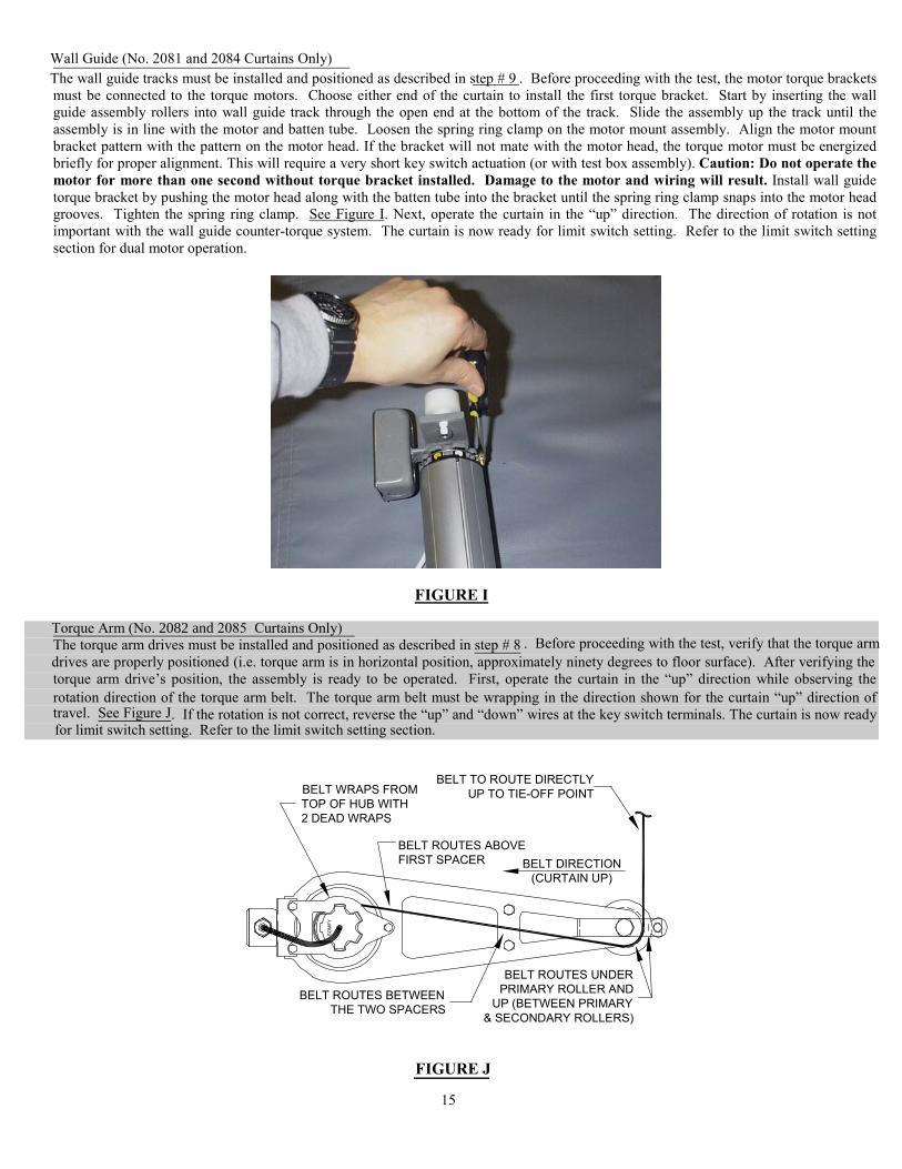
Wall Guide (No. 2081 and 2084 Curtains Only)
The wall guide tracks must be installed and positioned as described in step # 9 . Before proceeding with the test, the motor torque brackets
must be connected to the torque motors. Choose either end of the curtain to install the first torque bracket. Start by inserting the wall
guide assembly rollers into wall guide track through the open end at the bottom of the track. Slide the assembly up the track until the
assembly is in line with the motor and batten tube. Loosen the spring ring clamp on the motor mount assembly. Align the motor mount
bracket pattern with the pattern on the motor head. If the bracket will not mate with the motor head, the torque motor must be energized
briefly for proper alignment. This will require a very short key switch actuation (or with test box assembly). Caution: Do not operate the
motor for more than one second without torque bracket installed. Damage to the motor and wiring will result. Install wall guide
torque bracket by pushing the motor head along with the batten tube into the bracket until the spring ring clamp snaps into the motor head
grooves. Tighten the spring ring clamp. See Figure I. Next, operate the curtain in the “up” direction. The direction of rotation is not
important with the wall guide counter-torque system. The curtain is now ready for limit switch setting. Refer to the limit switch setting
section for dual motor operation.
FIGURE I Torque Arm (No. 2082 and 2085 Curtains Only)
The torque arm drives must be installed and positioned as described in step # 8 . Before proceeding with the test, verify that the torque arm
drives are properly positioned (i.e. torque arm is in horizontal position, approximately ninety degrees to floor surface). After verifying the
torque arm drive’s position, the assembly is ready to be operated. First, operate the curtain in the “up” direction while observing the
rotation direction of the torque arm belt. The torque arm belt must be wrapping in the direction shown for the curtain “up” direction of travel. See Figure J. If the rotation is not correct, reverse the “up” and “down” wires at the key switch terminals. The curtain is now ready for limit switch setting. Refer to the limit switch setting section.
FIGURE J
BELT ROUTES ABOVE
FIRST SPACER
SO
MF
Y
BELT ROUTES BETWEEN
THE TWO SPACERS
BELT WRAPS FROM
TOP OF HUB WITH
2 DEAD WRAPS
BELT ROUTES UNDER
PRIMARY ROLLER AND
UP (BETWEEN PRIMARY
& SECONDARY ROLLERS)
BELT TO ROUTE DIRECTLY
UP TO TIE-OFF POINT
BELT DIRECTION
(CURTAIN UP)

16
18. LIMIT SWITCH SETTING
The dual motor curtain requires that only one motor’s limit switch assembly is set. The second motor’s limit switch buttons are to remain
in the depressed position (no adjustment is necessary). Typically the limits on the torque motor closest to the synchronizer panel are
adjusted. Obviously, field conditions can vary, so for that reason, the torque motor that is more easily accessible should be the one that is
set.
The torque motor limits are quickly and easily set by simply depressing and releasing the torque motor limit switches, but first it will be
necessary to determine which limit switch stops a direction of operation. This is accomplished by performing the following test. Remove
the limit switch protective cover. Depress one switch and release it (switch is now up). Turn the key switch key in one direction. If the
curtain does not operate, the switch released controls that direction of travel. On the other hand if the curtain operates, the other limit
switch controls that direction of travel. Reset the limit previously released by pushing it down (switch is now down). Now, the limits are
ready to be set. To set the “up” limit, carefully raise the curtain to the desired up position or before the curtain comes in contact with the
overhead structure or hardware, then simply depress the switch (switch is now up) that controls the “up” direction of travel. The “up” limit
is now set. To set the “down” limit, lower the curtain until the curtain is completely down (batten tube slots are vertical), then depress the
switch (switch is now up) that controls the “down” direction of travel. The “down” limit is now set. Reinstall the limit switch protective
cover.
19. CURTAIN OPERATIONAL TEST
The curtain operation must be fully tested after installation to confirm that the limit switches and other curtain components are functioning
properly. It is imperative that this test is performed to assure safe and reliable performance for many years to come.
Note: The curtain torque motor is not a continuous duty motor. A thermal overload device will shut down the motor after four
minutes (approximately two cycles of operation). The thermal overload will automatically reset when the motor has cooled. To test the curtain “up” limit, turn the key at the key switch in the up direction (as noted on the key switch faceplate label). The curtain
should start raising (rolling) up until the “up“ limit automatically stops the direction of operation. Caution: Be prepared to manually
stop the curtain operation, if the limit switch does not stop the direction of travel automatically. If the “up” limit switch does not
stop the direction of travel at the desired location, reset the “up” limit according to step 18. Repeat the above steps to test the “down” limit
setting. Next, operate the curtain in either direction of travel. While operating the curtain, observe the curtain counter-torque assembly for
proper operation. The wall guide assembly (No. 2084 curtains only) should operate quietly, and without binding or catching on track
splices (if applicable). The torque arm (No. 2085 curtains only) should operate smoothly with the belt wrapping evenly on the drum while
centered (in the groove) under the guide roller. The belt must track inside the roller groove when the curtain is operating up or down. If
the belt does not track properly, ensure the belt tie-off point or curtain system is plumb. Adjust if necessary. After observing and testing
the initial operation of the curtain, operate the curtain several more cycles to confirm proper operation.
MODEL No. 2080 CENTER-ROLL® DIVIDER CURTAIN
MAINTENANCE INSTRUCTIONS
The Model No. 2080 Center-Roll® divider curtain is designed to operate for many years without any significant service performed.
Depending upon the usage of the unit, it is recommended that at least an annual inspection be made, at which time the following steps
should be taken:
1. GENERAL
Make certain the Porter key switch is not substituted and is located within full view (but not beneath) the divider curtain. Check the walls
in close proximity to the curtain for any type of protrusion that may interfere with the raising or lowering of the unit (i.e., new scoreboard,
chinning bars, etc.).
2. TORQUE MOTOR ASSEMBLY
The electric torque motor is permanently lubricated, maintenance free and designed for long life. The torque motor itself does not require
any type of scheduled inspection. However, the electric cord or other attached components should be inspected periodically for proper
alignment, damage, or wear.

25
2080 ELECTRICAL BREAKDOWN 120V
TYPE 2081
WALL GUIDE 1 MOTOR 2082
TORQUE BELT 1 MOTOR 2084
WALL GUIDE 2 MOTORS 2085
TORQUE BELT 2 MOTORS
KEY SWITCH
NOTE: FOR MULTI-
PLE SWITCHES ADD A MULTIPLE GANG SWITCHES,
RECEPTACLES, AND COVER PLATE
IN A SEPARATE LINE ITEM
ELEC00199300 (TUBE MOTOR ASSY W/ CORD REEL & CARRIAGE (120V) Includes: - (1) ELEC00199200 TUBE MO-TOR DRIVE ASSY. W/ STEEL CROWN 4 TERM. - (1) ELEC00185100 REEL AS-SEMBLY ELEC. CORD RETRAC-TOR 4 TERM XELE00791112 (1 WINCH PER
SWITCH) Includes: - (1) ELEC00042100 4 WIRE RECEPTACLE - (1) ELEC000470G0 SURFACE COVR 4PRG - (1) ELEC00086000 SWITCH ASBLY.
ELEC00214200 (TORQUE ARM DRIVE ASSY W/ CORD REEL & BELT)
Includes: - (1) ELEC00199000 TUBE MO-TOR ASSY WI4 TERMINALS - (1) ELEC00185100 REEL AS-SEMBLY ELEC. CORD RETRAC-TOR XELE00791112 (1 WINCH PER
SWITCH) Includes: - (1) ELEC00042100 4 WIRE RECEPTACLE - (1) ELEC000470G0 SURFACE COVR 4PRG - (1) ELEC00086000 SWITCH ASBLY.
(2) ELEC00199300 (TUBE MO-TOR ASSY W/ CORD REEL & CARRIAGE (120V)
Includes: - (1) ELEC00199200 TUBE MO-TOR DRIVE ASSY W/ STEEL CROWN 4 TERM. - (1) ELEC00185100 REEL AS-SEMBLY ELEC. CORD RETRAC-TOR 4 TERM ELEC00189100
(SYNCHRONIZER ASSEM-BLY- 110 VOLT)
ELEC00064000 (3-WIRE TWIST-
LOCK RECEPTACLE) ELEC001260G0 (1/2" DEEP
SURFACE COVER FOR 3 PRONG)
ELEC00086000 (SWITCH ASBLY) ELEC00248XXX (POWER CORD
ASSY. XXX FT LONG) ELEC00209000 (LOCKING CON-
NECTOR)
(2) ELEC00214200 (TORQUE ARM DRIVE ASSY W/ CORD REEL & BELT)
Includes: - (1) ELEC00199000 TUBE MO-TOR ASSY MOTOR WITH 4 TERMINALS - (1) ELEC00185100 REEL AS-SEMBLY ELEC. CORD RETRAC-TOR
ELEC00189100
(SYNCHRONIZER ASSEM-BLY- 110 VOLT)
ELEC00064000 (3-WIRE TWIST-
LOCK RECEPTACLE) ELEC001260G0 (1/2" DEEP
SURFACE COVER FOR 3 PRONG)
ELEC00086000 (SWITCH
ASBLY) ELEC00248XXX (POWER CORD
ASSY. XXX FT LONG) ELEC00209000 (LOCKING
CONNECTOR)
SPORTSONIC II
NOTE: ALL SPORTSONIC TRANSMITTER
(12002100) ARE TO BE ADDED IN A SEPARATE LINE
ITEM
ELEC00199300 (TUBE MOTOR ASSY W/ CORD REEL & CARRIAGE (120V)
Includes: - (1) ELEC00199200 TUBE MO-TOR DRIVE ASSY. W/ STEEL CROWN 4 TERM. - (1) ELEC00185100 REEL AS-SEMBLY ELEC. CORD RETRAC-TOR 4 TERM 12002200 (SPORTSONIC II
RECEIVER KIT) Includes: - (1) ELEC00064000 3-WIRE TWIST-LOCK RECEPTACLE - (1) ELEC001260G0 1/2" DEEP SURFACE COVER FOR 3 PRONG - (2) ELEC00221002 CABLE TIE 14" LG - (1) XELC12002200 SPORTSON-IC II GAMA
ELEC00214200 (TORQUE ARM DRIVE ASSY W/ CORD REEL & BELT)
Includes: - (1) ELEC00199000 TUBE MO-TOR ASSY WI4 TERMINALS - (1) ELEC00185100 REEL AS-SEMBLY ELEC. CORD RETRAC-TOR 12002200 (SPORTSONIC II
RECEIVER KIT) Includes: - (1) ELEC00064000 3-WIRE TWIST-LOCK RECEPTACLE - (1) ELEC001260G0 1/2" DEEP SURFACE COVER FOR 3 PRONG - (2) ELEC00221002 CABLE TIE 14" LG - (1) XELC12002200 SPORTSON-IC II GAMA
(2) ELEC00199300 (TUBE MO-TOR ASSY W/ CORD REEL & CARRIAGE (120V)
Includes: - (1) ELEC00199200 TUBE MO-TOR DRIVE ASSY W/ STEEL CROWN 4 TERM. - (1) ELEC00185100 REEL AS-SEMBLY ELEC. CORD RETRAC-TOR 4 TERM ELEC00189100
(SYNCHRONIZER ASSEMBLY- 110 VOLT)
ELEC00064000 (3-WIRE TWIST-
LOCK RECEPTACLE) ELEC001260G0 (1/2" DEEP
SURFACE COVER FOR 3 PRONG)
XELC12002300 (SPORTSONIC II
RECEIVER W/ KEY INPUT) ELEC00248XXX (POWER CORD
ASSY. XXX FT LONG) ELEC00209000 (LOCKING CON-
NECTOR)
(2) ELEC00214200 (TORQUE ARM DRIVE ASSY W/ CORD REEL & BELT)
Includes: - (1) ELEC00199000 TUBE MO-TOR ASSY MOTOR WITH 4 TERMINALS - (1) ELEC00185100 REEL AS-SEMBLY ELEC. CORD RETRAC-TOR
ELEC00189100
(SYNCHRONIZER ASSEMBLY- 110 VOLT)
ELEC00064000 (3-WIRE TWIST-
LOCK RECEPTACLE) ELEC001260G0 (1/2" DEEP
SURFACE COVER FOR 3 PRONG)
XELC12002300 (SPORTSONIC II
RECEIVER W/ KEY INPUT) ELEC00248XXX (POWER CORD
ASSY. XXX FT LONG) ELEC00209000 (LOCKING
CONNECTOR)
SPORTSONIC II W/ KEY SWITCH
NOTE: ALL
SPORTSONIC TRANSMITTER
(12002100) ARE TO BE ADDED IN A SEPARATE LINE
ITEM
ELEC00199300 (TUBE MOTOR ASSY W/ CORD REEL & CARRIAGE (120V)
Includes: - (1) ELEC00199200 TUBE MO-TOR DRIVE ASSY. W/ STEEL CROWN 4 TERM. - (1) ELEC00185100 REEL AS-SEMBLY ELEC. CORD RETRAC-TOR 4 TERM 12002250 (SPORTSONIC II
RECEIVER W/KEY INPUT KIT)
Includes: - (1) ELEC00064000 3-WIRE TWIST-LOCK RECEPTACLE - (1) ELEC001260G0 1/2" DEEP SURFACE COVER - (1) ELEC00086000 KEY SWITCH ASSY. - (2) ELEC00221002 CABLE TIE 14" LG - (1) XELC12002210 SPORTSON-IC II W/KEY GAMA XELE00791112 (KEY SWITCH W/
HOOK UP 1 MOTOR PER SWITCH)
ELEC00042100 (4 WIRE RECEP-
TACLE) ELEC000470G0 (1|2" SURFACE
COVER FOR 4 PRONG)
ELEC00214200 (TORQUE ARM DRIVE ASSY W/ CORD REEL & BELT)
Includes: - (1) ELEC00199000 TUBE MO-TOR ASSY WI4 TERMINALS - (1) ELEC00185100 REEL AS-SEMBLY ELEC. CORD RETRAC-TOR 12002250 (SPORTSONIC II
RECEIVER W/KEY INPUT KIT)
Includes: - (1) ELEC00064000 3-WIRE TWIST-LOCK RECEPTACLE - (1) ELEC001260G0 1/2" DEEP SURFACE COVER - (1) ELEC00086000 KEY SWITCH ASSY. - (2) ELEC00221002 CABLE TIE 14" LG - (1) XELC12002210 SPORTSON-IC II W/KEY GAMA XELE00791112 (KEY SWITCH W/
HOOK UP 1 MOTOR PER SWITCH)
ELEC00042100 (4 WIRE RECEP-
TACLE) ELEC000470G0 (1|2" SURFACE COVER FOR 4 PRONG)
(2) ELEC00199300 (TUBE MO-TOR ASSY W/ CORD REEL & CARRIAGE (120V)
Includes: - (1) ELEC00199200 TUBE MO-TOR DRIVE ASSY W/ STEEL CROWN 4 TERM. - (1) ELEC00185100 REEL AS-SEMBLY ELEC. CORD RETRAC-TOR 4 TERM ELEC00189100
(SYNCHRONIZER ASSEMBLY- 110 VOLT)
ELEC00064000 (3-WIRE TWIST-
LOCK RECEPTACLE) ELEC001260G0 (1/2" DEEP
SURFACE COVER FOR 3 PRONG)
XELC12002300 (SPORTSONIC II
RECEIVER W/ KEY INPUT) ELEC00248XXX (POWER CORD
ASSY. XXX FT LONG) ELEC00209000 (LOCKING CON-
NECTOR) ELEC00086000 (KEY SWITCH
ASSY.)
(2) ELEC00214200 (TORQUE ARM DRIVE ASSY W/ CORD REEL & BELT)
Includes: - (1) ELEC00199000 TUBE MO-TOR ASSY MOTOR WITH 4 TERMINALS - (1) ELEC00185100 REEL AS-SEMBLY ELEC. CORD RETRAC-TOR
ELEC00189100
(SYNCHRONIZER ASSEMBLY- 110 VOLT)
ELEC00064000 (3-WIRE TWIST-
LOCK RECEPTACLE) ELEC001260G0 (1/2" DEEP
SURFACE COVER FOR 3 PRONG)
XELC12002300 (SPORTSONIC II
RECEIVER W/ KEY INPUT) ELEC00248XXX (POWER CORD
ASSY. XXX FT LONG) ELEC00209000 (LOCKING
CONNECTOR) ELEC00086000 (KEY SWITCH
ASSY.)

26
2080 ELECTRICAL BREAKDOWN 120V CONTINUED
TYPE 2081
WALL GUIDE 1 MOTOR 2082
TORQUE BELT 1 MOTOR 2084
WALL GUIDE 2 MOTORS 2085
TORQUE BELT 2 MOTORS
POWR TOUCH 2.5
NOTE: THE TOTAL
QUANTITY OF CONTROL PANELS
(12555200) AND TOUCHPADS
(92555100) ARE TO BE ADDED AS A SEPARATE LINE
ITEM
(1) ELEC00199300 (TUBE MO-TOR ASSY W/ CORD REEL & CARRIAGE (120V) Includes: - (1) ELEC00199200 TUBE MO-TOR DRIVE ASSY. W/ STEEL CROWN 4 TERM. - (1) ELEC00185100 REEL ASSEMBLY ELEC. CORD RE-TRACTOR 4 TERM (1) ELEC00042100 (4-WIRE RECEPTACLE) (1) ELEC000470G0 (1/2" DEEP SURFACE COVER FOR 4 PRONG)
(1) ELEC00214200 (TORQUE ARM DRIVE ASSY W/CORD REEL & BELT) Includes: - (1) ELEC00199000 TUBE MO-TOR ASSY WI4 TERMINALS - (1) ELEC00185100 REEL AS-SEMBLY ELEC. CORD RETRAC-TOR (1) ELEC00042100 (4-WIRE RECEPTACLE) (1) ELEC000470G0 (1/2" DEEP SURFACE COVER FOR 4 PRONG)
(2) ELEC00199300 (TUBE MO-TOR ASSY W/ CORD REEL & CARRIAGE (120V) Includes: - (1) ELEC00199200 TUBE MOTOR DRIVE ASSY W/ STEEL CROWN 4 TERM. - (1) ELEC00185100 REEL AS-SEMBLY ELEC. CORD RETRAC-TOR 4 TERM (1) ELEC00189100 (SYNCHRONIZER ASSEMBLY- 110 VOLT) (1) ELEC00064000 (3-WIRE TWIST-LOCK RECEPTACLE) (1) ELEC001260G0 (1/2" DEEP SURFACE COVER FOR 3 PRONG) (1) ELEC00248XXX (POWER CORD ASBLY XXX FT LONG) (1) ELEC00209000 (LOCKING CONNECTOR)
(2) ELEC00214200 (TORQUE ARM DRIVE ASSY W/CORD REEL & BELT) Includes: - (1) ELEC00199000 TUBE MO-TOR ASSY MOTOR WITH 4 TERMINALS - (1) ELEC00185100 REEL AS-SEMBLY ELEC. CORD RETRAC-TOR
(1) ELEC00189100 (SYNCHRONIZER ASSEMBLY- 110 VOLT) (1) ELEC00064000 (3-WIRE TWIST-LOCK RECEPTACLE) (1) ELEC001260G0 (1/2" DEEP SURFACE COVER FOR 3 PRONG) (1) ELEC00248XXX (POWER CORD ASBLY XXX FT LONG) (1) ELEC00209000 (LOCKING CONNECTOR)
POWR TOUCH LCD
NOTE: THE TOTAL
QUANTITY OF CONTROL PANELS
(12600200) AND TOUCHPADS
(92500060) ARE TO BE ADDED AS A SEPARATE LINE
ITEM
(1) ELEC00199300 (TUBE MO-TOR ASSY W/ CORD REEL & CARRIAGE (120V) Includes: - (1) ELEC00199200 TUBE MO-TOR DRIVE ASSY. W/ STEEL CROWN 4 TERM. - (1) ELEC00185100 REEL ASSEMBLY ELEC. CORD RE-TRACTOR 4 TERM (1) ELEC00042100 (4-WIRE RECEPTACLE) (1) ELEC000470G0 (1/2" DEEP SURFACE COVER FOR 4 PRONG)
(1) ELEC00214200 (TORQUE ARM DRIVE ASSY W/CORD REEL & BELT) Includes: - (1) ELEC00199000 TUBE MO-TOR ASSY WI4 TERMINALS - (1) ELEC00185100 REEL AS-SEMBLY ELEC. CORD RETRAC-TOR (1) ELEC00042100 (4-WIRE RECEPTACLE) (1) ELEC000470G0 (1/2" DEEP SURFACE COVER FOR 4 PRONG)
(2) ELEC00199300 (TUBE MO-TOR ASSY W/ CORD REEL & CARRIAGE (120V) Includes: - (1) ELEC00199200 TUBE MOTOR DRIVE ASSY W/ STEEL CROWN 4 TERM. - (1) ELEC00185100 REEL AS-SEMBLY ELEC. CORD RETRAC-TOR 4 TERM (1) ELEC00189100 (SYNCHRONIZER ASSEMBLY- 110 VOLT) (1) ELEC00064000 (3-WIRE TWIST-LOCK RECEPTACLE) (1) ELEC001260G0 (1/2" DEEP SURFACE COVER FOR 3 PRONG) (1) ELEC00248XXX (POWER CORD ASBLY XXX FT LONG) (1) ELEC00209000 (LOCKING CONNECTOR)
(2) ELEC00214200 (TORQUE ARM DRIVE ASSY W/CORD REEL & BELT) Includes: - (1) ELEC00199000 TUBE MO-TOR ASSY MOTOR WITH 4 TERMINALS - (1) ELEC00185100 REEL AS-SEMBLY ELEC. CORD RETRAC-TOR
(1) ELEC00189100 (SYNCHRONIZER ASSEMBLY- 110 VOLT) (1) ELEC00064000 (3-WIRE TWIST-LOCK RECEPTACLE) (1) ELEC001260G0 (1/2" DEEP SURFACE COVER FOR 3 PRONG) (1) ELEC00248XXX (POWER CORD ASBLY XXX FT LONG) (1) ELEC00209000 (LOCKING CONNECTOR)

27
ELECTRIC WINCH FIELD WIRING DETAILS AND REQUIREMENTS (SINGLE MOTOR)

28
ELECTRIC MOTOR SYNCHRONIZER / KEY SWITCH WIRING DETAILS AND REQUIREMENTS (DUAL MOTOR)

29
FIELD WIRING DETAIL FOR CENTER-ROLL CURTAIN KEY SWITCH OPERATION SINGLE MOTOR
30
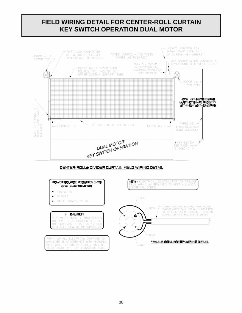
FIELD WIRING DETAIL FOR CENTER-ROLL CURTAIN KEY SWITCH OPERATION DUAL MOTOR

31
FIELD WIRING DETAIL FOR CENTER-ROLL CURTAIN SPORTSONIC II OPERATION SINGLE MOTOR

32
FIELD WIRING DETAIL FOR CENTER-ROLL CURTAIN SPORTSONIC II OPERATION DUAL MOTOR

33
FIELD WIRING DETAIL FOR CENTER-ROLL CURTAIN POWR-TOUCH OPERATION SINGLE MOTOR

34
FIELD WIRING DETAIL FOR CENTER-ROLL CURTAIN POWR-TOUCH OPERATION DUAL MOTOR

35
THIS WARNING IS GIVEN IN COMPLIANCE WITH CALIFORNIA’S PROPOSITION 65:
WARNING This product contains chemicals known to the
State of California to cause cancer, birth defects
THIS PRINT IS THE PROPERTY OF PORTER ATHLETIC EQUIPMENT COMPANY AND MAY NOT BE REPRODUCED WITHOUT WRITTEN PERMISSION

36
INSTALLER NOTES