Embed Size (px)
Citation preview
Center for Reliable Computing
TECHNICALREPORT
Diversity Techniques for Concurrent Error Detection
Subhasish Mitra
00-7 Center for Reliable ComputingGates Building 2A, Room 236Computer Systems Laboratory
June 2000 Dept. of Electrical Engineering and Computer ScienceStanford University
Stanford, California 94305
Abstract:This technical report contains the text of Subhasish Mitra’s PhD thesis “Diversity
Techniques for Concurrent Error Detection.”
Funding:This research was supported by the Advanced Research Projects Agency under
Contract No. DABT63-97-C-0024.
Copyright © 2000 by Subhasish Mitra.All rights reserved, including the right to reproduce this report, or portions thereof, in any
form.
ii
DIVERSITY TECHNIQUES FORCONCURRENT ERROR DETECTION
A DISSERTATION
SUBMITTED TO THE DEPARTMENT OF ELECTRICAL ENGINEERING
AND THE COMMITTEE ON GRADUATE STUDIES
OF STANFORD UNIVERSITY
IN PARTIAL FULFILLMENT OF THE REQUIREMENTS
FOR THE DEGREE OF
DOCTOR OF PHILOSOPHY
By
Subhasish Mitra
May 2000

iii
Copyright © by Subhasish Mitra 2000
All Rights Reserved

iv
I certify that I have read this dissertation and that in my opinion it is fully adequate, in
scope and quality, as a dissertation for the degree of Doctor of Philosophy.
_________________________________
Edward J. McCluskey (Principal Advisor)
I certify that I have read this dissertation and that in my opinion it is fully adequate, in
scope and quality, as a dissertation for the degree of Doctor of Philosophy.
_________________________________
Giovanni De Micheli
I certify that I have read this dissertation and that in my opinion it is fully adequate, in
scope and quality, as a dissertation for the degree of Doctor of Philosophy.
_________________________________
Bernard Widrow
Approved for the University Committee on Graduate Studies
_________________________________

v
To my parents
For their love, affection and support
“Thou hast made me endless, such is thy pleasure. This frail vessel thou emptiest again
and again, and fillest it ever with fresh life.
This little flute of a reed thou hast carried over hills and dales, and hast breathed
through it melodies eternally new.
At the immortal touch of thy hands my little heart loses its limits in joy and gives birth to
utterance ineffable.
Thy infinite gifts come to me only on these very small hands of mine. Ages pass, and still
thou pourest, and still there is room to fill.”
- Rabindranath Tagore
- Gitanjali (Song Offerings)
vi
ABSTRACT
Concurrent error detection (CED) techniques are widely used to ensure data
integrity in digital systems. Data integrity guarantees that the system outputs are either
correct or an error is indicated when incorrect outputs are produced. This dissertation
presents the results of theoretical and simulation studies of various CED techniques. The
CED schemes studied are based on diverse duplication, simple duplication of identical
implementations, and error-detection techniques like parity checking. The study aimed at
(1) a quantitative comparison of the effectiveness of different CED schemes, and (2)
developing design techniques for efficient concurrent error detection.
A CED scheme based on diverse duplication compares the outputs of two
different implementations of the same function and indicates an error when a mismatch
occurs. The idea of such a CED technique is derived from the general concept of design
diversity. The conventional notion of design diversity is qualitative and relies on
independent generation of different implementations. In this dissertation, a metric to
quantify design diversity is presented and used for analyzing CED schemes based on
diverse duplication.
A comparative study of different CED schemes by means of simulation
experiments and theoretical analysis concludes that, in the worst-case, diverse duplication
provides significantly better data integrity against multiple failures compared to other
CED schemes. This result is especially significant in the context of Common-Mode
Failures (CMFs). CMFs undermine the data integrity of any system with CED and
belong to a special class of multiple failures whose probability of occurrence can be as
high as that of single failures.
New techniques and synthesis algorithms have been developed for the first time to
efficiently design systems based on diverse duplication. New fault models for CMFs are
proposed and the possible failure mechanisms for the modeled CMFs are analyzed. In
addition, techniques for designing CED-based systems with guaranteed data integrity in
the presence of modeled CMFs are described.
vii
ACKNOWLEDGMENTS
I am deeply grateful to my advisor, Prof. Edward J. McCluskey, for his constant
guidance, support, and encouragement throughout my years at Stanford. He modeled the
qualities of an ideal teacher and an outstanding researcher that I aspire to emulate in my
career. I would also like to thank Mrs. Lois Thornhill McCluskey.
I would like to thank Prof. Bruce Wooley, my associate advisor, Prof. Bernard
Widrow, my committee chairman, for reading my dissertation, and Prof. Giovanni
DeMicheli for many interesting discussions and also for agreeing to be the fourth
member of my committee.
I would like to thank my colleagues (RATs) at the Center for Reliable Computing
(CRC) for helpful discussions, and companionship through the years: Mehmet Apaydin,
LaNae Avra, Jonathan Chang, Santiago Fernandez-Gomez, Vlad Friedman, Robert
Huang, Rajesh Kamath, Chat Khunpitiluck, Moon-jung Kim, Wern-Yan Koe, James Li,
Siyad Ma, Samy Makar, Rob Norwood, Nahmsuk Oh, Nirmal Saxena, Philip Shirvani,
Rudy Tan, Nur Touba, Chao-wen Tseng, Sanjay Wattal, Yoonjin Yoon and Catherine
Yu. Special thanks to Dr. Nirmal Saxena for his advice and guidance. I also thank
Siegrid Munda for her administrative support. Thanks to my professors at Stanford and
the CRC visitors Prof. Jacob Abraham, Prof. Bella Bose, Prof. Miroslaw Malek, Prof.
Mohammed Niamat and Prof. Dhiraj Pradhan for many interesting discussions.
I wish to thank my professors (especially, Prof. P. Bhattacharya, Prof. T. K. Dey,
Prof. A. K. Majumdar, Prof. P. Pal Chaudhuri, Prof. D. Sarkar of Indian Institute of
Technology, Kharagpur and Prof. D. Ghosh Dastidar and Prof. R. Dattagupta of Jadavpur
University, Calcutta) and teachers in India. I would also wish to thank my friends for
their support over the years that ranged from useful advice to frequent invitations over the
weekends. Thanks to Prof. P. Banerjee and Dr. R. K. Roy for their support during the
application process for my graduate studies in the United States.
I am very grateful to my parents for their continued love, support and
encouragement. I dedicate this thesis to them. I also thank my relatives and family-
friends in India for their continuing encouragement and support.
My research work at Stanford was supported by Defense Advanced Research
Projects Agency (DARPA) under Contract No. DABT63-94-C-0045 and DABT63-97-C-
0024.
viii
TABLE OF CONTENTS
Abstract........................................................................................................................ vi
Acknowledgments ....................................................................................................... vii
Table of Contents....................................................................................................... viii
List of Figures .............................................................................................................. xi
List of Tables............................................................................................................... xii
Chapter 1: Introduction ............................................................................................... 1
1.1 Background........................................................................................................... 1
1.2 A Brief Background on Concurrent Error Detection .............................................. 3
1.3 Concurrent Error detection and Diversity .............................................................. 5
1.4 Contributions ........................................................................................................ 7
1.5 Outline ................................................................................................................ 10
Chapter 2: A Design Diversity Metric and Analysis of Redundant Systems............ 11
2.1 D: A Design Diversity Metric.............................................................................. 11
2.2 Reliability Analysis............................................................................................. 13
2.3 Results Demonstrating the Effectiveness of Diversity.......................................... 17
2.4 Conclusions ........................................................................................................ 18
Chapter 3: Comparison of Various Concurrent Error Detection Techniques......... 19
3.1 Concurrent Error Detection ................................................................................. 19
3.2 An Overview of Various Concurrent Error Detection Techniques ....................... 20
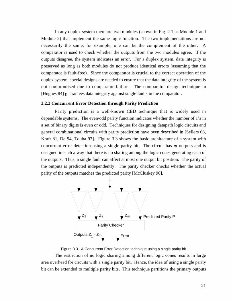
3.2.1 Concurrent Error Detection using Duplex Systems ....................................... 20
3.2.2 Concurrent Error Detection through Parity Prediction................................... 21
3.2.3 Concurrent Error Detection using Unidirectional Error Detecting Codes ...... 22
3.3 Vulnerability to Multiple Failures and CMFs: Simulation Results ....................... 24
3.4 Conclusions ........................................................................................................ 29
Chapter 4: Self-Testability of Duplex Systems .......................................................... 30
4.1 Self-Testability.................................................................................................... 30
ix
4.2 Identification of Non-Self-Testable Fault Pairs .................................................... 31
4.3 Self-Testability Enhancement Using Test Points.................................................. 32
4.3.1 Control Test Points ....................................................................................... 32
4.3.2 Observation Test Points ................................................................................ 34
4.4 Simulation Results............................................................................................... 35
4.5 Conclusions......................................................................................................... 36
Chapter 5: Combinational Logic Synthesis Techniques for Diversity ...................... 37
5.1 Problem Formulation........................................................................................... 37
5.2 Two-level Logic Synthesis .................................................................................. 38
5.3 Multi-level Logic Synthesis ................................................................................. 40
5.3.1 Single-Cube Extraction ................................................................................. 40
5.3.2 Double-Cube Extraction ............................................................................... 41
5.3.3 Re-substitution.............................................................................................. 42
5.3.4 Elimination ................................................................................................... 42
5.3.5 Simplification ............................................................................................... 42
5.4 Conclusions......................................................................................................... 43
Chapter 6: Common-Mode Failure Models and Redundant System Design............ 44
6.1 Common-Mode Fault Models .............................................................................. 44
6.2 Redundant System Design ................................................................................... 45
6.2.1 Redundant Systems Protected Against IR-CMF-1......................................... 45
6.2.2 Redundant Systems Protected Against IR-CMF-2......................................... 48
6.3 Conclusions......................................................................................................... 50
Chapter 7: Concluding Remarks................................................................................ 51
Publications from this Dissertation ............................................................................ 53
References.................................................................................................................... 54
Appendix A: Common-Mode Failures in Redundant VLSI Systems: A Survey ..........
(To appear in the IEEE Transactions on Reliability, 2000)
Appendix B: A Design Diversity Metric and Analysis of Redundant Systems .............
(Technical Report, CRC-TR-99-4, Center for Reliable Computing, Stanford University:http://crc.stanford.edu. An extended version of "A Design Diversity Metric andReliability Analysis of Redundant Systems," Proceedings of International TestConference, pp. 662-671, 1999)
x
Appendix C: Which Concurrent Error Detection Scheme to Choose ?
(To appear in the Proceedings of International Test Conference, 2000)
Appendix D: Fault Escapes In Duplex Systems
(Technical Report, CRC TR-00-1, Center for Reliable Computing, Stanford University:http://crc.stanford.edu. An extended version of "Fault Escapes in Duplex Systems,"Proceedings of VLSI Test Symposium, pp. 453-458, 2000)
Appendix E: Combinational Logic Synthesis For Diversity In Duplex Systems
(To appear in the Proceedings of International Test Conference, 2000)
Appendix F: Word-Voter: A New Voter Design For Triple Modular Redundant
Systems
(An extended version of "Word-Voter: A New Voter Design for Triple ModularRedundant Systems," Proceedings of VLSI Test Symposium, pp. 465-470, 2000)
Appendix G: Design of Redundant Systems Protected Against Common-Mode
Failures
(Technical Report, CRC-TR-00-2, Center for Reliable Computing, Stanford University,2000 http://crc.stanford.edu)
xi
LIST OF FIGURESFigure 1.1. General architecture of a concurrent error detection scheme .........................4
Figure 1.2. A Duplex System for Concurrent Error Detection.........................................6
Figure 2.1. Example of diversity................................................................................... 12
Figure 2.2. A discrete time model of the system ........................................................... 13
Figure 2.3. Common-Mode failure affecting both modules of a duplex system............. 14
Figure 2.4. Data integrity of a duplex system against common-mode failures ............... 15
Figure 2.5. Effect of diversity vs. time (for common-mode failures) ............................. 15
Figure 3.1. General architecture of concurrent error detection………………………….20
Figure 3.2. A Duplex System ....................................................................................... 20
Figure 3.3. A Concurrent Error Detection technique using a single parity bit................ 21
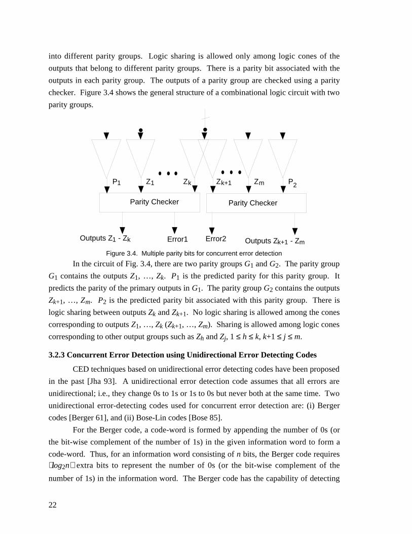
Figure 3.4. Multiple parity bits for concurrent error detection....................................... 22
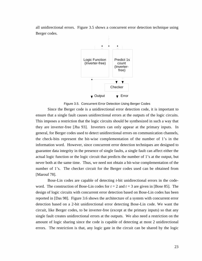
Figure 3.5. Concurrent Error Detection Using Berger Codes ........................................ 23
Figure 3.6. Concurrent error detection using Bose-Lin codes........................................ 24Figure 3.7. Venn diagram showing yi,j and zi,j ............................................................. 25
Figure 3.8. Systems with CED...................................................................................... 28
Figure 4.1. Control Test Points ..................................................................................... 33
Figure 4.2. Applications with testing phases ................................................................. 34
Figure 5.1. Illustration of Single-Cube extraction ......................................................... 41
Figure 5.2. Illustration of double-cube extraction ......................................................... 41
Figure 6.1. Conventional TMR..................................................................................... 46
Figure 6.2. TMR implementation protected against IR-CMF-1..................................... 46
Figure 6.3. The basic scheme for the second module in a duplex system....................... 49
xii
LIST OF TABLES
Table 2.1. Simulation results........................................................................................ 18
Table 3.1. Comparison of area overhead of different CED schemes ............................. 24
Table 3.2. Detection probability of erroneous outputs for different CED schemes ........ 26
Table 3.3. Improvement of detection probability of incorrect outputs using diverse
duplication over other schemes ............................................................................. 27
Table 4.1. Self-testing properties of duplex systems..................................................... 31
Table 4.2. Comparison of control and observation test points....................................... 34
Table 4.3. Test points for 100% self-testability ............................................................ 35
Table 4.4. Execution time using different techniques on Sun Ultra-Sparc-2.................. 36Table 6.1 Truth tables (a) Network N (b) Network N1 (c) Network N2......................... 47
Table 6.2. An example logic function........................................................................... 48
Table 6.3. Transformation T ........................................................................................ 50Table 6.4. Specification of N2....................................................................................... 49

xiii

1
Chapter 1
Introduction
1.1 Background
Dependability is one of the keys to business success. An Internet search on the
keyword “dependability” reveals that quality, integrity and dependability are among the
key selling points (in diverse sectors like aeronautics, avionics, pharmaceuticals, service
providers as well as automobile, chemical, computer hardware and software, electrical,
mechanical, medical equipment industry) for demonstrating the competitive advantages
of various products or services over others. Dependability can be defined as “the ability
to deliver highest quality product or service to the customer over a product life-cycle.”1
In a nutshell, dependability is one of the key areas in which a customer of a product or
service expects significant ROI (Return On Investment).
Since the inception of digital electronics, dependability has been an area of active
interest in the computer engineering community. The use of dependability features like
error-control coding and redundancy techniques in digital systems dates back to the
1950’s. Since then dependability techniques have been incorporated for a wide range of
applications, mainly in telephone switching networks, mainframe computers and servers,
military equipment, nuclear power plants, avionics and aircraft control systems. Today,
digital electronic components are used almost everywhere from the satellites in the space,
nuclear reactors, aircrafts, pace-makers, cars and computer servers to consumer goods
like phones, digital watches, video games, washing machines and dish-washers.
Anomalous behavior of these electronic components can have dangerous implications
leading to catastrophic accidents and even possible loss of human life. Hence, these
components must be “dependable”. At this point, it must be emphasized that the intended
system application determines its dependability requirements. As observed in
[McCluskey 85], since computers are used in a vast variety of applications, reliability
requirements vary tremendously. McCluskey uses the following two extreme examples
to illustrate the point: “For very low cost systems such as digital watches, small
calculators or games, the dependability requirements are minimal. The products are
expected to operate for a reasonable time after purchase. At the opposite extreme are
1 We got this definition from an Internet web-site that no longer exists.
2
systems like nuclear power plants or active control systems for civil aircraft in which
errors can cause loss of human life.”
Many publications on dependable computing can be obtained from archival
journals (e.g., the IEEE Transactions on Computers, IEEE Transactions on Reliability,
etc.), conference proceedings (e.g., Fault Tolerant Computing Symposium, International
Test Conference, etc.), text books (e.g. [Wakerly 78][Siewiorek 92], [Pradhan 96], etc.)
and the web pages of many research groups (e.g., Stanford Center for Reliable
Computing http://crc.stanford.edu, Center for Reliable and High Performance Computing
http://crhc.uiuc.edu).
One way to guarantee 100% dependability of computer systems is to produce
perfect hardware and software. However, this is not feasible. Even in a hypothetical
situation where perfect hardware or software can be shipped to the customer, there are
numerous sources (e.g., radiation, EMI, power-supply disturbances, noise, etc.) of system
errors in the field. For example, a survey on radiation induced failures in computer
electronics is available in [Ziegler 96]. In addition, the problems of various noise
sources, coupling effects and soft-errors are becoming even more critical in the era of
nanometer (Very Deep Sub-micron) technology [EE Times 99]; tackling these problems
with less aggressive design rules affects system performance, reducing expected revenue.
Thus, any system guaranteeing high dependability must be able to provide quality service
in the presence of errors that can affect the system in operation. A recent article in IEEE
Computer observes that the computer industry and computer research must focus on
availability, maintainability and scalability of computer systems; performance should be
less of an emphasis [Hennessy 99]. In addition, for emerging future technologies like
molecular computing [Collier 99] dependability will be a major cause of concern. This
concern has been expressed in many articles on molecular computing, including
[Peterson 00][Quinlan 99][Wall Street 99].
Some of the major components of dependability are reliability, availability,
testability, maintainability, data integrity and fault-tolerance. Reliability is the ability to
continue correct operation and is estimated by the probability that a system will survive
to time t. Availability is defined as the probability that a system is operational at time t
under maintenance. Testability can be defined as the ease of detecting and locating the
presence of a fault. Maintainability estimates the ease of repairing a system after a
failure. Data integrity is the property which ensures that the system outputs are either
correct or an error indication is generated when incorrect outputs are produced. In the
fault-tolerance literature, this is also referred to as the fault-secure property. The ability
to continue correct operation after a failure is called fault-tolerance.
3
The problem of assuring the required dependability of a digital electronic system
can be broadly classified into the following three different categories.
• Verification: It must be ensured that the system (hardware and software) design is
correct and free from design errors and bugs. For example, any error in the design of
electronic controllers used in cars must be identified and fixed. The problem of
design verification belongs to this category.
• Testing for manufacturing defects: For hardware designs, the manufactured parts
must be tested after fabrication [Abramovici 90][Needham 91]. This is because no
fabrication process is perfect and defects are introduced during manufacture. It is
undesirable to use these defective parts for designing systems (e.g., in motor cars,
pace-makers, etc.). Some of these defective parts can be identified during the testing
phase. However, some parts may have latent defects or weaknesses (also called
flaws) that may cause the part to fail (permanently or intermittently) in the field.
These defects are the sources of early-life failures (also called infant mortality).
Reliability screening techniques [Hnatek 95][Hao 93][Chang 96][Gulati 93] can be
used to reduce the number of shipped parts with these latent defects.
• Failure detection and recovery in the field: In addition to latent defects that can cause
intermittent failures, there are many sources of failures during system operation in the
field. The effects of these failures can be temporary or permanent. For systems with
high dependability, it is important to be able to detect errors affecting the system in
operation so that appropriate action can be initiated. For example, for satellites in the
space or air-craft control systems, field failures can have catastrophic consequences
(e.g., loss of human lives) or can cause huge monetary losses.
Concurrent error detection (CED) is a technique that checks the system operation
on-line to detect the presence of any temporary or permanent failure. The primary
objective of any CED technique is to make a system dependable against field failures.
The primary focus of this dissertation is on concurrent error detection.
1.2 A Brief Background on Concurrent Error Detection
Concurrent error detection (CED) techniques have been widely used in
commercial digital systems since the 1960’s. Almost all CED techniques function
according to the following principle: Let us suppose that the system under consideration
realizes a function f and produces output f(i) in response to an input sequence i. A CED
scheme generally contains another unit which predicts some special characteristic of the
system-output f(i) for every input sequence i. Finally, a checker unit checks whether the
4
special characteristic of the output actually produced by the system in response to input
sequence i is the same as the one predicted and produces an error signal when a
mismatch occurs. Some examples of the characteristics of f(i) are f(i) itself, its parity
(indicating whether the number of 1’s in an output word is even or odd), 1’s count, 0’s
count, transition count, residue modulo a fixed number, etc. For a detailed explanation of
these techniques please refer to Appendix C. The architecture of a general CED scheme
is shown in Fig. 1.1. Any CED scheme is characterized by the class of failures in the
presence of which the system data integrity is preserved.
Input
Function f Output Characteristic Predictor
Output
Predicted Output Characteristic
Checker
Error
Figure 1.1. General architecture of a concurrent error detection scheme
CED techniques have been used for both combinational and sequential logic
modules. The basic objectives behind the use of concurrent error detection are: (1)
detection of errors as early as possible so that corrective action can be initiated before
data corruption; and (2) identifying the Field Replaceable Unit (FRU) (e.g., a chip or
board). An overview of the CED techniques used in IBM mainframes from 1960’s to
1981 have been reported in [Hsiao 81]. For example, in the IBM 7030 system, parity
checking was used for the dataflow paths and a CED scheme based on modulo-3 residue
codes was used for floating point arithmetic. In addition, CED techniques based on
parity prediction and duplication were used. CED techniques have also been used in the
IBM S/360, IBM Enterprise System/9000 Type 9021 processors, IBM S/390 consisting
of G4 CMOS processor chip, the HP Enterprise server, VAX 8600 and systems from
companies like Tandem (Compaq), Hitachi, Sperry/Univac and many other companies.
While many publications are available on IBM systems, information on CED techniques
5
used by other companies can be obtained by searching for patents from the IBM patent
server (http://womplex.patents.ibm.com). In the IBM 9021 system, concurrent error
detection based on parity prediction was used for adders, counters, shifters, comparators,
etc. and for some sequential control logic modules; residue codes (modulo-3) were used
for a high-speed multiplier; for combinational control logic, hardware duplication was
used [Chen 92]. In the IBM S/390 system [Webb 97], the instruction unit and the
execution unit are duplicated in toto on the G4 CMOS processor chip. The execution unit
consists of the fixed-point (binary adder, BCD adder, bit-rotator, mask generator, bit-wise
logical and merge elements) and the floating-point units. For the VAX-8600 case,
mainly parity prediction has been used for concurrent error detection in the ALU and the
floating-point units [Siewiorek 92].
In [Siewiorek 92], an overview of different CED techniques used for general-
purpose processors and high-availability systems are presented. Among the high-
availability systems, CED techniques based on duplication and parity prediction have
been used in the AT&T telephone switching processors, and systems from Tandem and
Stratus.
In this dissertation, the problem of concurrent error detection is studied in the
context of reliable reconfigurable systems [Saxena 00]. Systems designed using Field
Programmable Gate Arrays (FPGAs) (from companies like Actel, Altera, Atmel, Xilinx)
or special processors (from companies like Chameleon Systems
http://www.chameleonsystems.com) are examples of reconfigurable systems. The
hardware available in these systems can be programmed in the field depending on the
application to be executed. The reconfigurability of these systems can be utilized to
obtain reliability by detecting the presence of errors using CED techniques, locating the
faulty parts and reconfiguring the system for the given application so that the faulty parts
are not used. For a reconfigurable system, the Field Replaceable Unit (FRU) is not the
entire chip or board, but only a small part of the reconfigurable system (e.g., logic blocks
or interconnection switches in FPGAs). With such a fine granularity of the FRU, it is
important to incorporate CED techniques at the module level for the combinational or
sequential logic circuits implemented on a reconfigurable system.
1.3 Concurrent Error detection and Diversity
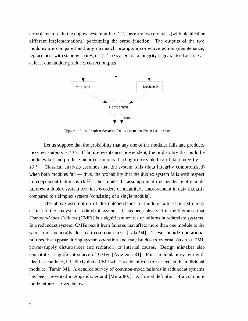
Any CED technique introduces some redundancy into the system. Duplication in
the form of self-checking pairs is the simplest form of redundancy that can be used for
concurrent error detection. Figure 1.2 illustrates the use of duplication for concurrent
6
error detection. In the duplex system in Fig. 1.2, there are two modules (with identical or
different implementations) performing the same function. The outputs of the two
modules are compared and any mismatch prompts a corrective action (maintenance,
replacement with standby spares, etc.). The system data integrity is guaranteed as long as
at least one module produces correct outputs.
Module 1 Module 2
Comparator
Error
Figure 1.2. A Duplex System for Concurrent Error Detection
Let us suppose that the probability that any one of the modules fails and produces
incorrect outputs is 10-6. If failure events are independent, the probability that both the
modules fail and produce incorrect outputs (leading to possible loss of data integrity) is
10-12. Classical analysis assumes that the system fails (data integrity compromised)
when both modules fail — thus, the probability that the duplex system fails with respect
to independent failures is 10-12. Thus, under the assumption of independence of module
failures, a duplex system provides 6 orders of magnitude improvement in data integrity
compared to a simplex system (consisting of a single module).
The above assumption of the independence of module failures is extremely
critical to the analysis of redundant systems. It has been observed in the literature that
Common-Mode Failures (CMFs) is a significant source of failures in redundant systems.
In a redundant system, CMFs result from failures that affect more than one module at the
same time, generally due to a common cause [Lala 94]. These include operational
failures that appear during system operation and may be due to external (such as EMI,
power-supply disturbances and radiation) or internal causes. Design mistakes also
constitute a significant source of CMFs [Avizienis 84]. For a redundant system with
identical modules, it is likely that a CMF will have identical error effects in the individual
modules [Tamir 84]. A detailed survey of common-mode failures in redundant systems
has been presented in Appendix A and [Mitra 00c]. A formal definition of a common-
mode failure is given below.
7
“A common-mode failure (CMF) is the result of an event(s) which, because of
dependencies, causes a coincidence of failure states of components in two or more
separate channels of a redundancy system, leading to the defined system failing to
perform its intended function” [sic][Watson 79].
For a duplex system with two identical modules, if the CMF probability is 10-7,
then the probability that the duplex system fails is 10-7. Thus, the simple addition of
redundancy through replication does not help protect the system against CMFs.
A natural component of the study of common-mode failures is the study of
diversity. As early as 1970, diversity was identified as an effective antidote for common-
mode failures [Jacobs 70]. However, the major thrust was on incorporating diversity at
various steps in the design of a nuclear reactor control. Design diversity was proposed in
[Avizienis 77] to protect redundant computing systems against common-mode failures.
Design Diversity is an approach in which the hardware and software elements that are to
be used for multiple computations (in a redundant system) are not just replicated, but are
independently generated to meet a system's requirements [Avizienis 84]. Thus, the basic
idea behind using design diversity is that, with different implementations, the error
effects of a CMF will possibly be different so that error detection is possible.
The concept of design diversity has been used in both software and hardware
systems. N-version programming [Chen 78] is a technique in which three different
versions of the same software (generated independently) are used to design a redundant
software system. In addition to N-version programming, there are other diversity
techniques (e.g., data diversity, functional diversity, etc.) for protecting redundant
software systems against common-mode failures. A comprehensive report on these
techniques is given in Appendix A. Hardware design diversity has been used in the past
to design redundant hardware systems. Examples of systems using hardware design
diversity include the Primary Flight Computer (PFC) system of Boeing 777 [Riter 95],
the space shuttle, Airbus 320 [Briere 93] and many other commercial systems. For the
Boeing 777, three different processors with different architectures (from AMD, Intel and
Motorola) are used in the PFC system.
1.4 Contributions
From the previous discussion, it is clear that the concept of diversity is qualitative.
This means, given two diverse duplex systems, for example, there is no way to tell which
one should be used so that the system data integrity is maximized. Thus, as pointed out
in [Littlewood 96], there is a need to answer questions such as: “what is diversity? Are
8
these designs more diverse than those? How diverse are these two designs?” In the
literature, these questions are not answered clearly; the need for answering these
questions has also been expressed in [Tamir 84].
This dissertation presents a metric for design diversity. The metric is very simple
and can be applied to both hardware and software systems. It has also been shown that
the metric can be used to perform reliability and availability analysis of redundant
systems to quantify the gains obtained from using diversity in redundant systems. Thus,
for the first time, it is possible to make quantitative comparisons among different diverse
redundant systems.
With the new concept of a diversity metric, it is possible to quantify the
vulnerability of diverse duplex systems to multiple failures and CMFs. In this
dissertation, the concept of the diversity metric has been used to quantify the
vulnerability of other popular CED schemes (e.g., parity checking) to multiple failures
and CMFs. While these CED techniques have been well-known for many years and the
problem of multiple failures and CMFs affecting these schemes has been acknowledged,
there has been no systematic study comparing the vulnerability of these CED schemes to
these failures. Almost all earlier studies considered only the area overhead as a criterion
for comparing these different CED schemes. A study (using computer simulations and
theoretical analysis) was conducted, for the first time, to compare different CED schemes
based on their area overhead and their vulnerability to multiple failures and CMFs. The
study reveals that diverse duplication provides significantly better protection (data
integrity) against multiple failures and CMFs compared to other CED techniques.
It has been observed earlier that the conventional notion of diversity relies on
“independent” generation of “different” implementations. However, with the help of the
diversity metric, it is possible to develop algorithms for synthesizing “different”
implementations in order to guarantee that the diversity is maximized. New synthesis
algorithms for designing two-level and multi-level combinational logic circuits, using
diversity as a component of the cost function during synthesis, have been presented in
this dissertation.
While diversity can provide some protection against multiple failures and CMFs,
it is well-known that the data integrity of a diverse duplex system is not guaranteed in the
presence of these failures. Thus, it is important to detect these failures so that appropriate
actions can be initiated. New test point insertion techniques for detecting multiple
failures (CMFs constitute a subset of multiple failures) in duplex systems have been
developed in this dissertation. The proposed algorithm developed for implementing these
techniques show orders of magnitude improvement over a conventional exact algorithm
9
with minimal loss in the accuracy of the results. Moreover, the approximate algorithm is
very flexible, its execution time can be tuned according to user requirements (accuracy,
processing time, etc.), and it is pessimistic. This guarantees that all fault pairs (and
hence, CMFs) can be detected with minimal overhead.
Finally, new CMF models have been proposed for the first time. While numerous
publications discuss the problem of CMFs, the absence of CMF models impedes research
progress in this field. Special techniques for designing redundant systems that guarantee
full protection against the modeled CMFs have been presented in this dissertation.
While redundancy based on duplication is useful for concurrent error detection,
Triple Modular Redundancy (TMR) is widely used for masking faults during system
operation. A TMR system contains three modules (with the same or different
implementations) performing the same function and their outputs are connected to a
majority voter. The majority voter produces the system outputs. A new voter design for
TMR systems has been developed in this dissertation. The advantages of the new voter
design over conventional voters in enhancing the data integrity of TMR systems have
also been demonstrated.
The major contributions of this dissertation are:
• A metric for quantifying diversity in redundant systems has been developed for the
first time. Such a metric permits quantitative comparisons of different redundant
systems.
• Reliability and availability of redundant systems using this metric have been
analyzed.
• The idea of the diversity metric has been extended to quantify the vulnerability of
different CED techniques to multiple failures and CMFs.
• A study comparing the advantages and disadvantages (e.g., area overhead,
vulnerability to multiple failures and CMFs) of different CED techniques has been
presented. The comparative study quantifies the advantages of diverse duplication
techniques over other CED schemes.
• Test point insertion techniques that guarantee detection of multiple failures and CMFs
in duplex systems have been developed.
• New combinational logic synthesis algorithms have been formulated for designing
duplex systems in order to maximize the gains obtained from diversity.
• A thorough characterization of common-mode failures in redundant systems has been
developed.
• A new voter design for Triple Modular Redundant systems has been developed.
Simulation results demonstrate that the data integrity of TMR systems with the new
10
voter is at least an order of magnitude better than that of TMR systems with
conventional voters.
• New CMF models have been proposed and techniques for designing redundant
systems protected against modeled CMFs have been described.
1.5 Outline
Chapter 2 presents the design diversity metric and reliability analysis of redundant
systems. Chapter 3 presents a study conducted to compare different concurrent error
detection techniques based on their area overhead and their vulnerability to multiple
failures and CMFs. Techniques that guarantee 100% detection of multiple and common-
mode failures in duplex systems are developed in Chapter 4. Chapter 5 presents
combinational logic synthesis techniques for diversity. Fault models for CMFs and
techniques to design redundant systems protected against modeled CMFs are proposed in
Chapter 6. Chapter 7 concludes this dissertation.
11
Chapter 2
A Design Diversity Metric and Analysis of RedundantSystems
Design diversity has long been used to protect redundant systems against
common-mode failures (CMFs). In [Avizienis 84], design diversity was defined as “the
independent generation of two or more software or hardware elements to satisfy a given
requirement”. The conventional notion of diversity is qualitative and does not provide a
basis to compare reliabilities of two diverse systems. For quantitative analysis, a metric
for design diversity is needed. In this chapter, a metric to quantify diversity among
several designs has been presented. Based on this metric, analytical models have been
derived to perform reliability and availability analysis of redundant systems. A detailed
discussion and the simulation results can be found in Appendix B.
2.1 D: A Design Diversity Metric
Assume that we are given two implementations (logic networks) of a logicfunction, an input probability distribution and faults fi and fj that occur in the first and the
second implementations, respectively. The diversity di,j with respect to the fault pair (fi,
fj) is the conditional probability that the two implementations do not produce identical
errors, given that faults fi and fj have occurred [Mitra 99a].
For a given fault model, the design diversity metric, D, between two designs is the
expected value of the diversity with respect to different fault pairs. Mathematically, wehave D = P f f di j i j
f fi j
( , ) ,( , )∑ , where P (fi, fj) is the probability of the fault pair (fi, fj).
D is the probability that the two implementations either produce error-free outputs
or produce different error patterns on their outputs in the presence of faults affecting the
two implementations.
Consider any combinational logic function with n inputs and a single output. The
fault model considered is such, that a combinational circuit remains combinational in the
presence of the fault. Let us consider two implementations (N1 and N2) of the given
combinational logic function.
12
The joint detectability, ki,j, of a fault pair (fi, fj) is the number of input patterns that detect
both fi and fj. This definition follows from the idea of detectability developed in
[McCluskey 88].
Assuming all input patterns are equally likely, di,j = 1 -ki j
n,
2.
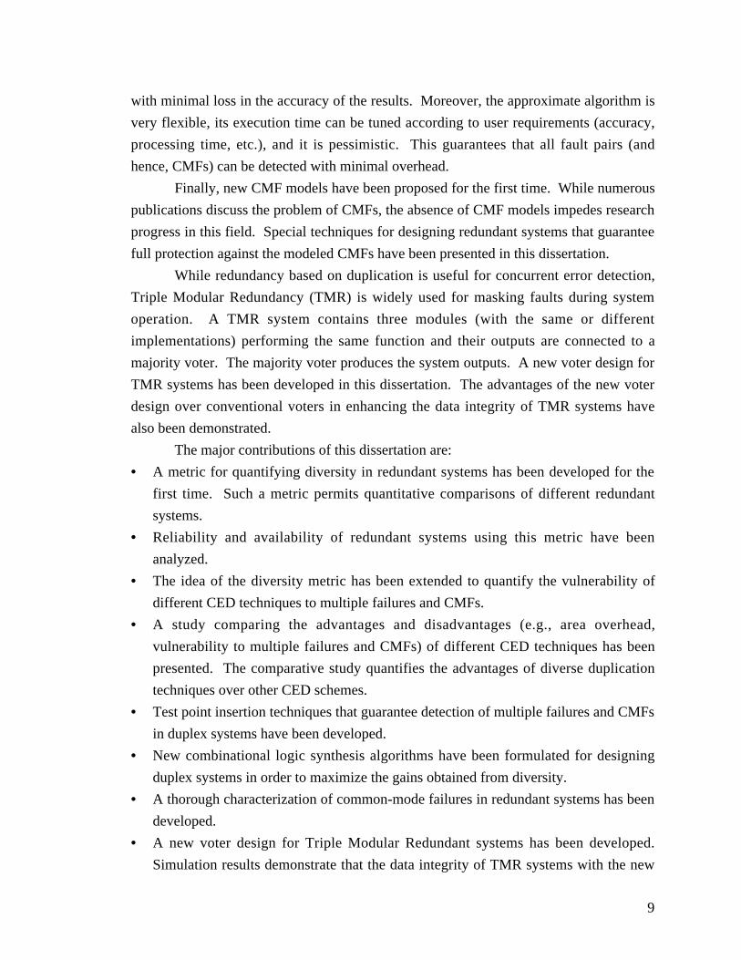
For example, consider the two implementations of the logic function Z = AB + AC
shown in Fig. 2.1.
& &
+
AB C
Z
W
+
&
CB A
Z
Y
(a) (b)Figure 2.1. Example of diversity
Consider the fault f1 = w stuck-at-0 in the implementation of Fig. 2.1a and the
fault f2 = y stuck-at-0 in the implementation of Fig. 2.1b. The set of input combinations
that detect f1 is {ABC = 101}. The set of input combinations that detect f2 is {ABC =
111, 101, 110}. It is clear that ABC = 101 is the only input combination that detects both
f1 and f2. Hence, the joint detectability k1,2 of the fault pair (f1, f2) is 1. If a duplex system
consisting of the two implementations in Fig. 2.1 is affected by the fault pair (f1, f2), then
ABC = 101 is the only input combination for which both implementations will produce
identical errors. If we assume that all input combinations are equally likely, then the d1,2
for the fault pair (f1, f2) is 118
78
− = .
The di,j’s generate a diversity profile for the two implementations with respect to a
fault model. Consider a duplex system consisting of the two implementations under
consideration. In response to any input combination, the implementations can produce
one of the following cases at their outputs: (1) Both of them produce correct outputs. (2)
One of them produces the correct output and the other produces an incorrect output. (3)
Both of them produce the same incorrect value.
For the first case, the duplex system will produce correct outputs. For the second
case, the system will report a mismatch so that appropriate recovery actions can be taken.
13
However, for the third case, the system will produce an incorrect output without reporting
a mismatch — thus, for the third case, the system data integrity of the system is not
preserved.
Assuming all fault pairs are equally probable and there are m fault pairs (fi, fj),
then the D metric for the two implementations is: D = 1m
di ji j
,,∑ .
The above illustration of the design diversity metric can also be extended to
multiple-output combinational logic circuits (shown in Appendix B), sequential circuits,
software programs and for redundant systems with more than two modules. For small or
medium-sized systems, the exact value of the diversity metric can be calculated manually
or using computer programs. For large systems, the value can be estimated by using
simulation techniques.
2.2 Analysis
Analysis of redundant systems using the design diversity metric has been reported
in detail in Appendix B and [Mitra 99a]. This section presents some important results
obtained from the analysis.
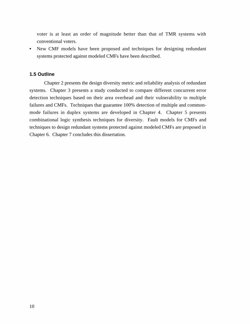
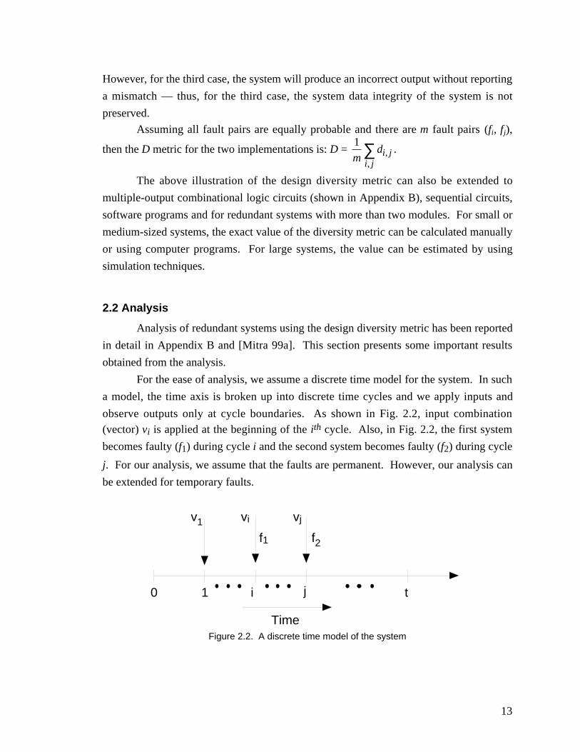
For the ease of analysis, we assume a discrete time model for the system. In such
a model, the time axis is broken up into discrete time cycles and we apply inputs and
observe outputs only at cycle boundaries. As shown in Fig. 2.2, input combination(vector) vi is applied at the beginning of the ith cycle. Also, in Fig. 2.2, the first system
becomes faulty (f1) during cycle i and the second system becomes faulty (f2) during cycle
j. For our analysis, we assume that the faults are permanent. However, our analysis can
be extended for temporary faults.
0 1 i j t
Time
v1 vi vj
f1 f2
Figure 2.2. A discrete time model of the system
14
Time
1 i i+1 t
f1 f2
d1,2 d1,2 d1,2
0
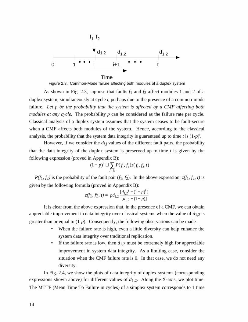
Figure 2.3. Common-Mode failure affecting both modules of a duplex system
As shown in Fig. 2.3, suppose that faults f1 and f2 affect modules 1 and 2 of a
duplex system, simultaneously at cycle i, perhaps due to the presence of a common-mode
failure. Let p be the probability that the system is affected by a CMF affecting both
modules at any cycle. The probability p can be considered as the failure rate per cycle.
Classical analysis of a duplex system assumes that the system ceases to be fault-secure
when a CMF affects both modules of the system. Hence, according to the classical
analysis, the probability that the system data integrity is guaranteed up to time t is (1-p)t.However, if we consider the di,j values of the different fault pairs, the probability
that the data integrity of the duplex system is preserved up to time t is given by the
following expression (proved in Appendix B):
( ) ( , ) ( , , ),
1 1 2 1 2
1 2
− + ∑p P f f z f f tt
f f
P(f1, f2) is the probability of the fault pair (f1, f2). In the above expression, z(f1, f2, t) is
given by the following formula (proved in Appendix B):
z(f1, f2, t) = pdd p
d p
t t
1 21 2
1 2
1
1,,
,
[ ( ) ]
[ ( )]
− −− −
It is clear from the above expression that, in the presence of a CMF, we can obtainappreciable improvement in data integrity over classical systems when the value of d1,2 is
greater than or equal to (1-p). Consequently, the following observations can be made
• When the failure rate is high, even a little diversity can help enhance the
system data integrity over traditional replication.• If the failure rate is low, then d1,2 must be extremely high for appreciable
improvement in system data integrity. As a limiting case, consider the
situation when the CMF failure rate is 0. In that case, we do not need any
diversity.
In Fig. 2.4, we show the plots of data integrity of duplex systems (correspondingexpressions shown above) for different values of d1,2. Along the X-axis, we plot time.
The MTTF (Mean Time To Failure in cycles) of a simplex system corresponds to 1 time
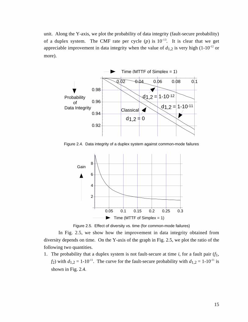
15
unit. Along the Y-axis, we plot the probability of data integrity (fault-secure probability)
of a duplex system. The CMF rate per cycle (p) is 10-13. It is clear that we getappreciable improvement in data integrity when the value of d1,2 is very high (1-10-12 or
more).
Time (MTTF of Simplex = 1)
Probability ofData Integrity
0.02 0.04 0.06 0.08 0.1
0.92
0.94
0.96
0.98
Classical
d1,2 = 1-10-12
d1,2 = 1-10-11
d1,2 = 0
Figure 2.4. Data integrity of a duplex system against common-mode failures
Time (MTTF of Simplex = 1)
Gain
0.05 0.1 0.15 0.2 0.25 0.3
2
4
6
8
Figure 2.5. Effect of diversity vs. time (for common-mode failures)
In Fig. 2.5, we show how the improvement in data integrity obtained from
diversity depends on time. On the Y-axis of the graph in Fig. 2.5, we plot the ratio of the
following two quantities.1. The probability that a duplex system is not fault-secure at time i, for a fault pair (f1,
f2) with d1,2 = 1-10-11. The curve for the fault-secure probability with d1,2 = 1-10-11 is
shown in Fig. 2.4.
16
2. The probability that a duplex system is not fault-secure at time i, for fault pair (f1, f2)
with d1,2 = 1-10-12. The curve for the fault-secure probability with d1,2 = 1-10-12 is
also shown in Fig. 2.4. The failure rate per cycle is 10-13.
We call this ratio the gain. This quantity gives us a measure of the data integrityimprovement obtained by using the second duplex system (with d1,2 = 1-10-12) instead of
the first (d1,2 = 1-10-11). Along the X-axis, we plot time.
As Fig. 2.5 shows, the gain obtained from diversity diminishes with time. For
some applications (e.g., control hardware for aircraft landing), the system may be used
only for a certain amount of time; this period of operation of the system is called the
mission time of the system. From the graph in Fig. 2.5 we can conclude that if the
mission time (time of operation) of the system is short, we can obtain around an order of
magnitude improvement in data integrity by using a diverse duplex system. However, if
the mission time is too long, we may not get any improvement in data integrity by using
diversity. Thus, our analysis technique enables us to derive relationships among the data
integrity of a duplex system, the diversity incorporated to protect the system against
common-mode failures and the mission time. Hence, our design diversity metric is a
very fundamental property and can be used to understand different trade-offs associated
with the design of dependable systems using redundancy.
The importance between data integrity analysis and the system mission time is
demonstrated using the following example. Consider two duplex systems A and B. Let
us suppose that system A and B contain identical and diverse implementations of the
same logic function, respectively. Suppose that the analysis of data integrity
improvement (similar to the curve in Fig. 2.5) shows that the gain value is around 10when the mission time is T1 but decreases to 1 at mission time equal to T2. This implies
that, for applications with mission time less than or equal to T1, the system data integrity
obtained by using system B (diverse) will be an order of magnitude better than system A.However, if the mission time of the application is greater than T2, there will be no gain in
data integrity by choosing system B over system A. This can probably mean that neither
system is worth using and we must design another system with sufficient diversity to
obtain significant data integrity improvement for such long mission time. Another
alternative is to reduce the mission time and periodically test and/or checkpoint the
system.
The design diversity metric can be used to perform availability analysis of duplex
systems in the presence of CMFs [Mitra 99b]. These analysis techniques have been
reported in Appendix B.
17
2.3 Results Demonstrating the Effectiveness of Diversity
In order to quantify the effectiveness of diversity in redundant systems, we
present some results obtained through computer simulations. We considered
combinational logic circuits from the MCNC benchmark suite for simulation purposes.
For generating different designs, we synthesized logic circuits after applying multi-level
optimizations using the rugged script available in sis [Sentovich 92]. We subsequently
mapped the multi-level logic circuits to the LSI Logic G-10p technology library [LSI 96].
Next, we complemented the outputs in the truth tables of the benchmark circuits to
generate new truth tables. We used the same synthesis procedure for these new truth
tables. Finally, we added inverters at the outputs of the new designs obtained.
Since we did not find any data on common-mode failure mechanisms, we
performed the following sets of experiments to estimate the effect of diversity in the
presence of common-mode failures. In a duplex system with identical implementations,
we can find a one-to-one correspondence between the leads of the two copies. Hence, forthese duplicated systems, we injected single stuck-at fault pairs (f1, f2) such that f1 and f2
affect lead i of Module 1 and Module 2, respectively. This corresponds to a worst-casescenario. Note that, in the presence of f1 and f2, the two modules behave exactly in the
same way. Hence, they can be called common-mode faults. In the presence of these
faults, the two implementations never produce different erroneous outputs; hence, thepresence of these faults cannot be detected. Let us suppose that the faults f1 and f2,
resulting from a CMF, affect the two implementations of the duplex system at cycle c.
The data-corruption latency is defined to be the number of cycles from c until both
implementations produce the same erroneous output. The idea of data-corruption latency
similar to the concept of error-latency defined in [Shedletsky 76]. For the benchmark
circuits, we calculated the data corruption latency for these common-mode faults using
exhaustive simulation (the formula is derived in Appendix B).
For duplex systems with different implementations, we cannot establish a one-to-one correspondence between the leads of the two copies. Hence, for each fault f1 in
Module 1, we found the fault f2 in Module 2 with the minimum value of the data
corruption latency using exhaustive simulation. Hence, the fault pair (f1, f2) is called the
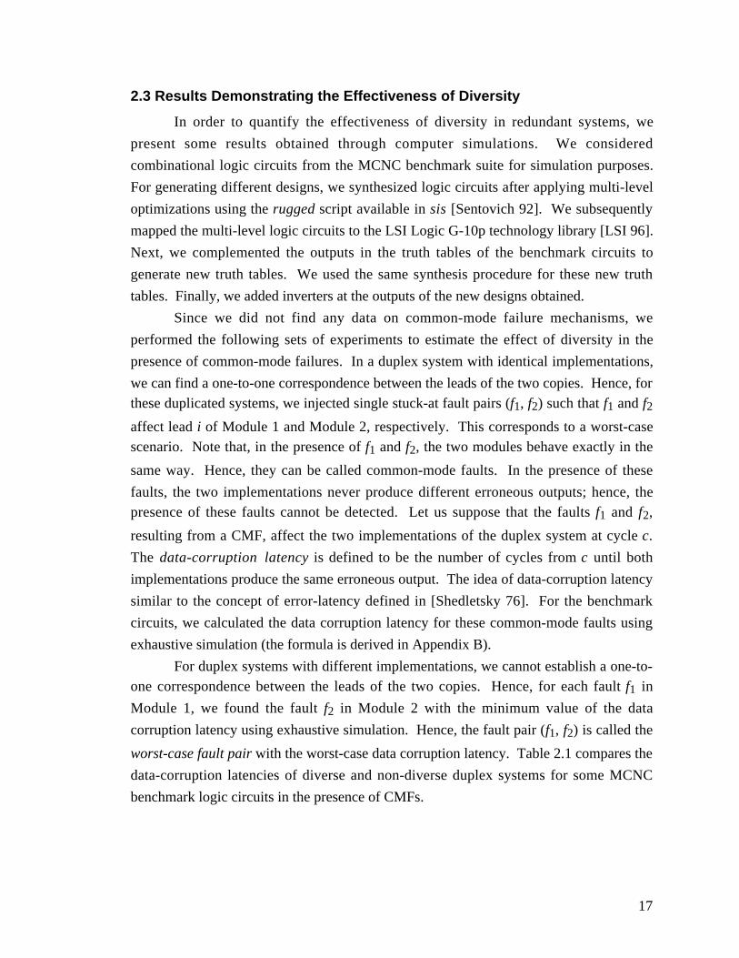
worst-case fault pair with the worst-case data corruption latency. Table 2.1 compares the
data-corruption latencies of diverse and non-diverse duplex systems for some MCNC
benchmark logic circuits in the presence of CMFs.
18
Table 2.1. Simulation resultsCircuitName
Duplex SystemType
Worst Data-CorruptionLatency (cycles)
Z5xp1 Identical 10Diverse 1711
clip Identical 35Diverse 372
inc Identical 16Diverse 1645
rd84 Identical 21Diverse 301
The results in Table 2.1 show a distinct advantage in using different
implementations over non-diverse designs for common-mode faults. This is because the
worst-case data-corruption latency of a CMF in a diverse duplex system is at least an
order of magnitude greater than that of a CMF in a duplex system with identical
implementations. It may be argued that a system may produce an error signal before
producing corrupt outputs; in that case, the system data integrity will be preserved. As
mentioned earlier in this section, this scenario cannot happen in the presence of a CMF in
a duplex system with identical implementations (assuming that a CMF affects identical
leads in both modules for a duplex system with identical implementations); it can only
happen in the presence of CMFs in diverse duplex systems. Hence, the results in Table
2.1 are pessimistic for diverse duplex systems.
2.4 Conclusions
The conventional concept of design diversity is qualitative and does not provide a
basis to compare the reliabilities of two diverse systems. For the first time, a metric has
been developed to quantify diversity among several designs. Analytical models for
reliability and availability analysis using the design diversity metric have been derived.
In this chapter, the analysis technique has been used to quantify the data integrity of
duplex systems with diversity. The analysis shows simple relationships among system
data integrity, design diversity, system failure rate, and mission time. Since CMFs can be
viewed as worst-case multiple module failures, the above observations can be made for
multiple module failures in redundant systems.
19
Chapter 3
Comparison of Various Concurrent Error DetectionTechniques
As observed in Chapter 1, concurrent error detection (CED) techniques are widely
used to enhance system dependability [Sellers 68, Kraft 81, Wakerly 78, Chen 92,
Pradhan 96]. Conventional CED techniques are based on hardware duplication (duplex
systems) and error-detection codes (e.g., parity codes). In this chapter, we present
quantitative results to compare six CED schemes based on their area overhead and their
vulnerability to multiple and common-mode failures. Complete details of our analysis
technique and the simulation results are presented in Appendix C.
3.1 Concurrent Error Detection
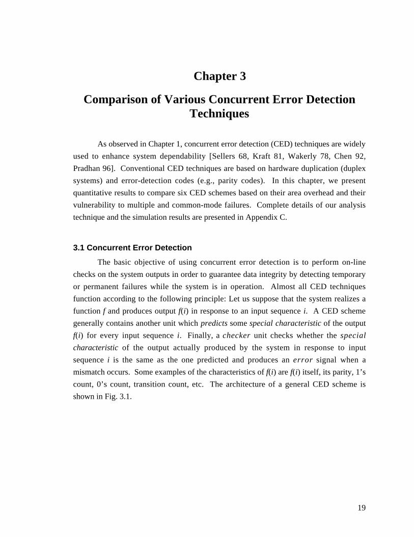
The basic objective of using concurrent error detection is to perform on-line
checks on the system outputs in order to guarantee data integrity by detecting temporary
or permanent failures while the system is in operation. Almost all CED techniques
function according to the following principle: Let us suppose that the system realizes a
function f and produces output f(i) in response to an input sequence i. A CED scheme
generally contains another unit which predicts some special characteristic of the output
f(i) for every input sequence i. Finally, a checker unit checks whether the special
characteristic of the output actually produced by the system in response to input
sequence i is the same as the one predicted and produces an error signal when a
mismatch occurs. Some examples of the characteristics of f(i) are f(i) itself, its parity, 1’s
count, 0’s count, transition count, etc. The architecture of a general CED scheme is
shown in Fig. 3.1.
20
Input
Function f Output Characteristic Predictor
Output
Predicted Output Characteristic
Checker
Error
Figure 3.1. General architecture of a concurrent error detection scheme
3.2 An Overview of Various Concurrent Error Detection Techniques
In this section, we present a brief overview of several CED schemes based on
duplication, parity prediction, Berger codes and Bose-Lin codes. These techniques are
very general and can be applied to any system, unlike some other application-specific
error detection techniques like inverse checking [Sellers 68], assertion checking
[Mahmood 84] and algorithm-based fault tolerance [Huang 84].
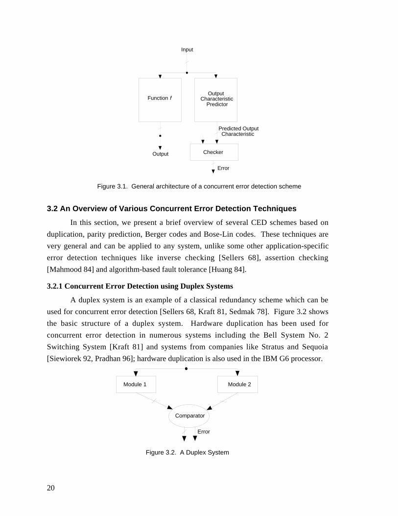
3.2.1 Concurrent Error Detection using Duplex Systems
A duplex system is an example of a classical redundancy scheme which can be
used for concurrent error detection [Sellers 68, Kraft 81, Sedmak 78]. Figure 3.2 shows
the basic structure of a duplex system. Hardware duplication has been used for
concurrent error detection in numerous systems including the Bell System No. 2
Switching System [Kraft 81] and systems from companies like Stratus and Sequoia
[Siewiorek 92, Pradhan 96]; hardware duplication is also used in the IBM G6 processor.
Module 1 Module 2
Comparator
Error
Figure 3.2. A Duplex System
21
In any duplex system there are two modules (shown in Fig. 2.1 as Module 1 and
Module 2) that implement the same logic function. The two implementations are not
necessarily the same; for example, one can be the complement of the other. A
comparator is used to check whether the outputs from the two modules agree. If the
outputs disagree, the system indicates an error. For a duplex system, data integrity is
preserved as long as both modules do not produce identical errors (assuming that the
comparator is fault-free). Since the comparator is crucial to the correct operation of the
duplex system, special designs are needed to ensure that the data integrity of the system is
not compromised due to comparator failure. The comparator design technique in
[Hughes 84] guarantees data integrity against single faults in the comparator.
3.2.2 Concurrent Error Detection through Parity Prediction
Parity prediction is a well-known CED technique that is widely used in
dependable systems. The even/odd parity function indicates whether the number of 1’s in
a set of binary digits is even or odd. Techniques for designing datapath logic circuits and
general combinational circuits with parity prediction have been described in [Sellers 68,
Kraft 81, De 94, Touba 97]. Figure 3.3 shows the basic architecture of a system with
concurrent error detection using a single parity bit. The circuit has m outputs and is
designed in such a way that there is no sharing among the logic cones generating each of
the outputs. Thus, a single fault can affect at most one output bit position. The parity of
the outputs is predicted independently. The parity checker checks whether the actual
parity of the outputs matches the predicted parity [McCluskey 90].
Z1 Z2 Zm Predicted Parity P
Parity Checker
ErrorOutputs Z1 - Zm
Figure 3.3. A Concurrent Error Detection technique using a single parity bit
The restriction of no logic sharing among different logic cones results in large
area overhead for circuits with a single parity bit. Hence, the idea of using a single parity
bit can be extended to multiple parity bits. This technique partitions the primary outputs
22
into different parity groups. Logic sharing is allowed only among logic cones of the
outputs that belong to different parity groups. There is a parity bit associated with the
outputs in each parity group. The outputs of a parity group are checked using a parity
checker. Figure 3.4 shows the general structure of a combinational logic circuit with two
parity groups.
Z1 Zm
Parity Checker
P1
Outputs Z1 - Zk
Zk Zk+1 P2
Parity Checker
Outputs Zk+1 - ZmError1 Error2
Figure 3.4. Multiple parity bits for concurrent error detection
In the circuit of Fig. 3.4, there are two parity groups G1 and G2. The parity group
G1 contains the outputs Z1, …, Zk. P1 is the predicted parity for this parity group. It
predicts the parity of the primary outputs in G1. The parity group G2 contains the outputs
Zk+1, …, Zm. P2 is the predicted parity bit associated with this parity group. There is
logic sharing between outputs Zk and Zk+1. No logic sharing is allowed among the cones
corresponding to outputs Z1, …, Zk (Zk+1, …, Zm). Sharing is allowed among logic cones
corresponding to other output groups such as Zh and Zj, 1 ≤ h ≤ k, k+1 ≤ j ≤ m.
3.2.3 Concurrent Error Detection using Unidirectional Error Detecting Codes
CED techniques based on unidirectional error detecting codes have been proposed
in the past [Jha 93]. A unidirectional error detection code assumes that all errors are
unidirectional; i.e., they change 0s to 1s or 1s to 0s but never both at the same time. Two
unidirectional error-detecting codes used for concurrent error detection are: (i) Berger
codes [Berger 61], and (ii) Bose-Lin codes [Bose 85].
For the Berger code, a code-word is formed by appending the number of 0s (or
the bit-wise complement of the number of 1s) in the given information word to form a
code-word. Thus, for an information word consisting of n bits, the Berger code requires log2n extra bits to represent the number of 0s (or the bit-wise complement of the
number of 1s) in the information word. The Berger code has the capability of detecting
23
all unidirectional errors. Figure 3.5 shows a concurrent error detection technique using
Berger codes.
Output
Logic Function (Inverter-free)
Predict 1s count(Inverter- free)
Checker
Error
Figure 3.5. Concurrent Error Detection Using Berger Codes
Since the Berger code is a unidirectional error detection code, it is important to
ensure that a single fault causes unidirectional errors at the outputs of the logic circuits.
This imposes a restriction that the logic circuits should be synthesized in such a way that
they are inverter-free [Jha 93]. Inverters can only appear at the primary inputs. In
general, for Berger codes used to detect unidirectional errors on communication channels,
the check-bits represent the bit-wise complementation of the number of 1’s in the
information word. However, since concurrent error detection techniques are designed to
guarantee data integrity in the presence of single faults, a single fault can affect either the
actual logic function or the logic circuit that predicts the number of 1’s at the output, but
never both at the same time. Thus, we need not obtain a bit-wise complementation of the
number of 1’s. The checker circuit for the Berger codes used can be obtained from
[Marouf 78].
Bose-Lin codes are capable of detecting t-bit unidirectional errors in the code-
word. The construction of Bose-Lin codes for t = 2 and t = 3 are given in [Bose 85]. The
design of logic circuits with concurrent error detection based on Bose-Lin codes has been
reported in [Das 98]. Figure 3.6 shows the architecture of a system with concurrent error
detection based on a 2-bit unidirectional error detecting Bose-Lin code. We want the
circuit, like Berger codes, to be inverter-free (except at the primary inputs) so that any
single fault creates unidirectional errors at the outputs. We also need a restriction on the
amount of logic sharing since the code is capable of detecting at most 2 unidirectional
errors. The restriction is that, any logic gate in the circuit can be shared by the logic
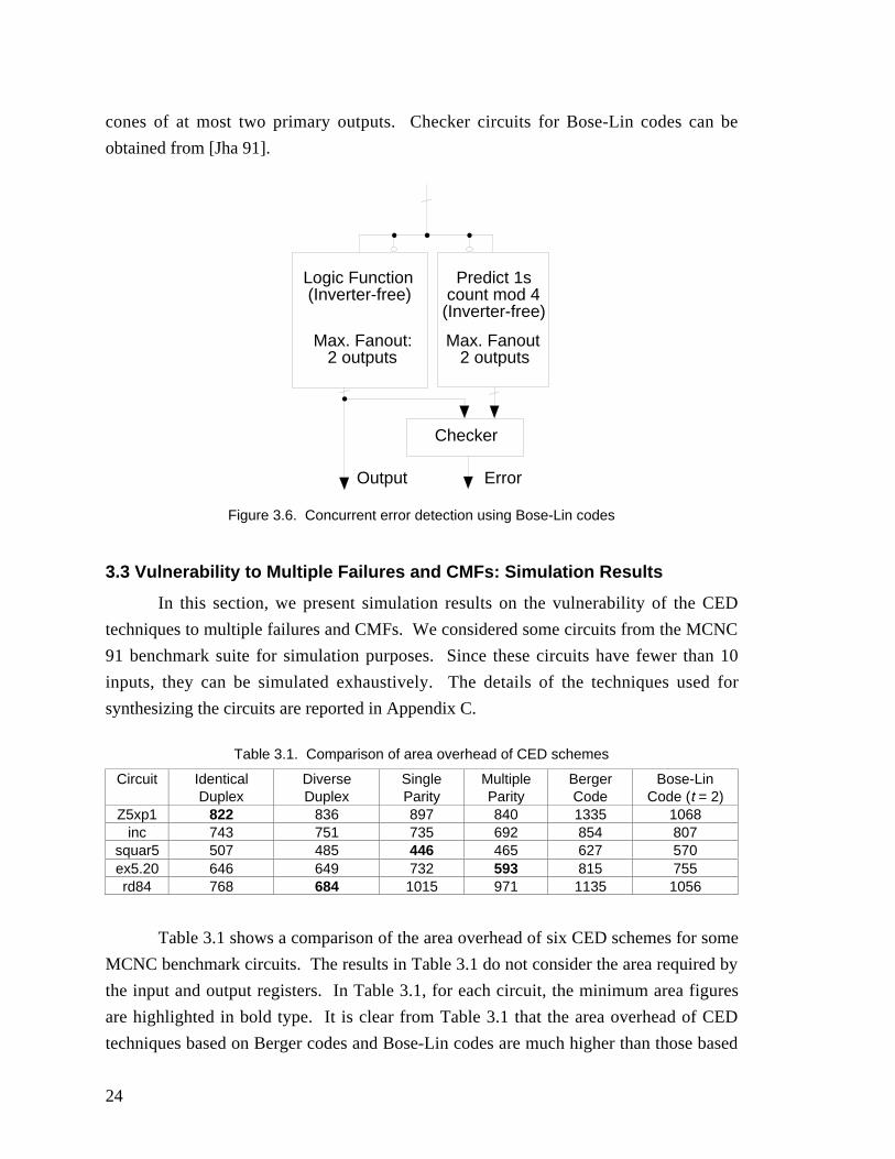
24
cones of at most two primary outputs. Checker circuits for Bose-Lin codes can be
obtained from [Jha 91].
Output
Logic Function (Inverter-free)
Predict 1s count mod 4 (Inverter-free)
Checker
Error
Max. Fanout: 2 outputs
Max. Fanout 2 outputs
Figure 3.6. Concurrent error detection using Bose-Lin codes
3.3 Vulnerability to Multiple Failures and CMFs: Simulation Results
In this section, we present simulation results on the vulnerability of the CED
techniques to multiple failures and CMFs. We considered some circuits from the MCNC
91 benchmark suite for simulation purposes. Since these circuits have fewer than 10
inputs, they can be simulated exhaustively. The details of the techniques used for
synthesizing the circuits are reported in Appendix C.
Table 3.1. Comparison of area overhead of CED schemes
Circuit IdenticalDuplex
DiverseDuplex
SingleParity
MultipleParity
BergerCode
Bose-LinCode (t = 2)
Z5xp1 822 836 897 840 1335 1068inc 743 751 735 692 854 807
squar5 507 485 446 465 627 570ex5.20 646 649 732 593 815 755rd84 768 684 1015 971 1135 1056
Table 3.1 shows a comparison of the area overhead of six CED schemes for some
MCNC benchmark circuits. The results in Table 3.1 do not consider the area required by
the input and output registers. In Table 3.1, for each circuit, the minimum area figures
are highlighted in bold type. It is clear from Table 3.1 that the area overhead of CED
techniques based on Berger codes and Bose-Lin codes are much higher than those based
25
on parity prediction or duplication. A similar observation has been made by earlier
researchers [Zeng 99]. Hence, for the rest of the chapter, we will focus mainly on a
comparative analysis of CED techniques based on duplication and parity prediction.
In dependable systems, it is realistic to assume that corrective action is initiated
after the system generates an error signal. Thus, for any system with concurrent error
detection, data integrity is guaranteed as long as the system does not produce an
undetected corrupt output before indicating the presence of an error. In the following
discussion, we focus on systems consisting of combinational logic circuits. However, the
entire discussion can be extended for sequential logic circuits.
The probability that the data integrity of a combinational logic system isguaranteed up to time t in the presence of a fault pair (fi, fj) is derived in the following
way. Let us suppose that the probability that the system produces correct outputs in thepresence of (fi, fj) is yi,j. The probability that the system produces incorrect outputs that
can be detected is zi,j. Figure 3.7 shows a Venn diagram that can be used to explain the
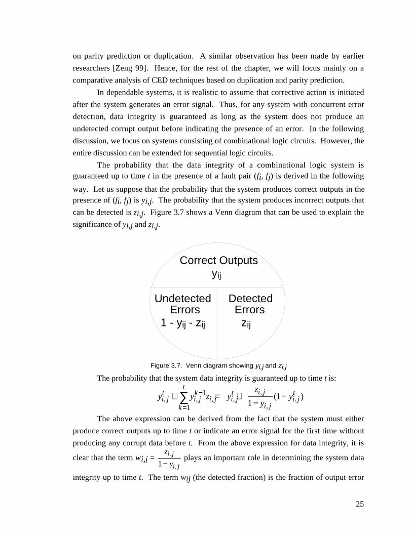
significance of yi,j and zi,j.
Correct Outputsyij
Detected Errors
zij
Undetected Errors1 - yij - zij
Figure 3.7. Venn diagram showing yi,j and zi,j
The probability that the system data integrity is guaranteed up to time t is:
y y z yz
yyi j
ti jk
i jk
t
i jt i j
i ji jt
, , , ,,
,.( )+ = +
−−−
=∑ 1
1 11
The above expression can be derived from the fact that the system must either
produce correct outputs up to time t or indicate an error signal for the first time without
producing any corrupt data before t. From the above expression for data integrity, it is
clear that the term wi,j = z
yi j
i j
.
,1 − plays an important role in determining the system data
integrity up to time t. The term wij (the detected fraction) is the fraction of output error
26
events detected in the presence of the fault pair (fi, fj). If the value of this term is 1 the
system either produces correct outputs or indicates erroneous situations when incorrect
outputs are produced. If the value is 0 the system never produces any error signal when
incorrect outputs are produced. Note that, if a CED-based system produces correct
outputs for all input combinations even in the presence of a fault, then the fault is
redundant.
We used the following procedure to estimate the protection against multiple and
common-mode failures provided by CED techniques based on duplication and parityprediction. For each single-stuck-at fault fi in each of these circuits, we identified another
single-stuck-at fault fj in the same circuit so that the value of wi,j is the minimum over all
fj’s through exhaustive simulation of all fault pairs and all input combinations. Hence,
the fault pair (fi, fj) can be regarded as a worst-case fault pair. Finally, we averaged the
wi,j’s over all the worst-case fault pairs to obtain the average value of the worst-case
detected fraction of incorrect outputs. Such a metric is pessimistic because we are
considering the worst-case fault pairs. The results are shown in Table 3.2. The
benchmark circuits are small enough so that exhaustive simulation is possible.
Table 3.2. Detection probability of erroneous outputs for CED schemes
Circuit IdenticalDuplex
DiverseDuplex
MultipleParity
Z5xp1 0 0.70 0.46inc 0 0.68 0.45
squar5 0 0.55 0.53ex5.20 0 0.3 0.2rd84 0 0.66 0.51
For duplex systems with identical implementations of the two modules, the worst-
case fault pairs affect the corresponding leads of both modules. In that case, the system
produces correct outputs or identical errors that cannot be detected. Hence, the value ofwi,j is 0 for all worst-case fault pairs in duplex systems with identical implementations.
Table 3.3 shows the improvement in the probability of detecting incorrect outputs in
diverse duplex systems compared to other CED techniques. The improvement in the
probability of detecting erroneous outputs obtained by diverse duplication over any other
CED scheme is defined as: system)duplex diversein detected outputsct Pr(Incorre-1
)scheme CED by the detected outputsIncorrect Pr(1− .
For example, consider the example of the benchmark circuit Z5xp1. For a duplex system
with identical implementations, the probability that erroneous outputs will be detected in
the presence of worst-case fault pairs is 0; i.e., the probability that erroneous outputs will
27
not be detected is 1. Likewise, for a diverse duplex system, the probability that erroneous
outputs will be detected in the presence of worst-case fault pairs is 0.7; therefore, the
probability that erroneous outputs will not be detected is 0.3. Thus, we obtain around 3
times improvement in the detectability of erroneous outputs by using diverse duplication
instead of identical duplication.
Table 3.3. Improvement of detection probability of incorrect outputs using diverse duplicationover other schemes
Circuit IdenticalDuplex
MultipleParity
Z5xp1 3 1.8inc 3 1.7
squar5 2 1.04ex5.20 1.5 1.14rd84 3 1.5
Tables 3.2 and 3.3 demonstrate the advantages of using diverse duplex systems
over other CED schemes. It may be noted that for diverse duplex systems, we foundworst-case fault pairs with the value of wi,j equal to 1. This means that, even in the
worst-case, system data integrity is guaranteed for these fault pairs in the diverse duplex
system. However, we did not find such worst-case fault pairs for systems with parity
checking.
The analysis presented in this section is pessimistic because it considers only theworst-case fault pairs. For the best case analysis, for every fault fi in the circuit we can
always identify a fault fj such that the value of wi,j is 1. These two can be faults in the
same module of a duplex system or the same logic cone for a CED scheme based on
parity prediction. Thus, a best-case analysis does not help us in comparing the
vulnerability of various CED schemes to CMFs and multiple failures. Additional results
on the comparison of the multiple and common-mode failure vulnerability of various
CED techniques are reported in Appendix C.
The simulation results demonstrate the advantages of diverse duplication in
providing protection against multiple failures and CMFs compared to other CED
schemes. Analytical techniques to quantify the vulnerability of various CED techniques
to multiple failures and CMFs, and to explain the above simulation results are presented
in Appendix C. These techniques make assumptions about the behavior of CED systems
in the presence of failures. Open problems for more sophisticated and general analysis of
failure behaviors in CED systems are also presented in Appendix C.
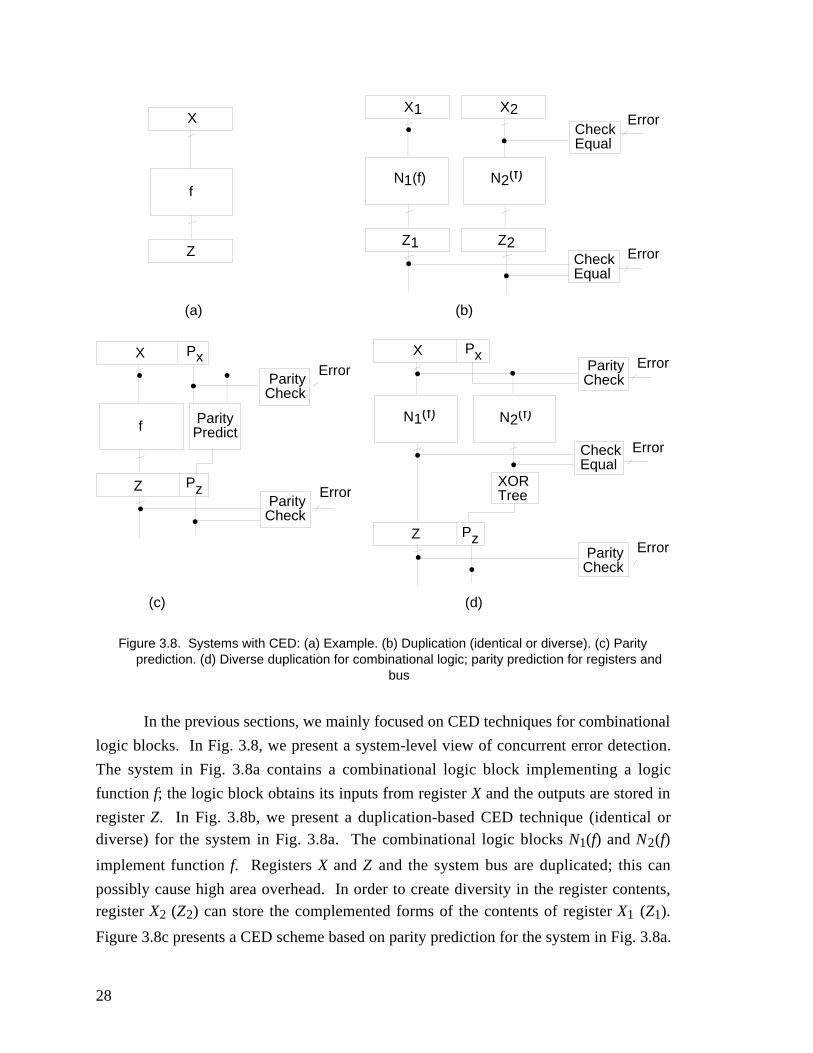
28
X
Z
f
X1
Z1
N1(f)
X2
Z2
N2(f)
CheckEqual
CheckEqual
Error
Error
(a) (b)
X
Z
f
ParityCheck
ParityCheck
Error
Error
Px
Pz
ParityPredict
X
Z
N1(f) N2(f)
ParityCheck
ParityCheck
Error
Error
(d)
Px
CheckEqual
Error
XORTree
Pz
(c)
Figure 3.8. Systems with CED: (a) Example. (b) Duplication (identical or diverse). (c) Parityprediction. (d) Diverse duplication for combinational logic; parity prediction for registers and
bus
In the previous sections, we mainly focused on CED techniques for combinational
logic blocks. In Fig. 3.8, we present a system-level view of concurrent error detection.
The system in Fig. 3.8a contains a combinational logic block implementing a logic
function f; the logic block obtains its inputs from register X and the outputs are stored in
register Z. In Fig. 3.8b, we present a duplication-based CED technique (identical ordiverse) for the system in Fig. 3.8a. The combinational logic blocks N1(f) and N2(f)
implement function f. Registers X and Z and the system bus are duplicated; this can
possibly cause high area overhead. In order to create diversity in the register contents,register X2 (Z2) can store the complemented forms of the contents of register X1 (Z1).
Figure 3.8c presents a CED scheme based on parity prediction for the system in Fig. 3.8a.
29
Each register has a single parity bit (Px for X and Pz for Z). It has been demonstrated in
this chapter through simulation that the area overhead of combinational logic blocks with
parity prediction is marginally less than that of duplication; however, if the number of
register flip-flops and bus lines are counted, the scheme in Fig. 3.8c has significantly less
area overhead than Fig. 3.8b. Figure 3.8d presents a CED scheme that uses diverse
duplication for combinational logic blocks and parity prediction for registers and bus
lines. Thus, we can achieve significant improvement in protection against multiple and
common-mode failures (through diverse duplication) while the total area overhead is
comparable to that of parity prediction (Fig. 3.8c). For this purpose, we need a tree of
XOR gates, as shown in Fig. 3.8d. The CED scheme in Fig. 3.8d needs two extra 2-input
XOR gates and one 2-input OR gate (XOR-tree and the equality checker) for each output
of the combinational logic block compared to the CED scheme in Fig. 3.8c. Note that,
the XOR tree may have significant delay overhead. This delay overhead can be reduced
by increasing the number of parity bits (i.e., the number of extra flip-flops in the
registers). Interesting problems analyzing this area-delay trade-off can be studied in this
context. The XOR-tree of Fig. 3.8d can be eliminated if the parity bit is generated from a
dual-rail checker that can be used to check the outputs of the combinational logic
[Nicolaidis 93]. Routing overhead of the designs in Fig. 3.8b, 3.8c and 3.8d has not been
considered in the above discussion and is a topic of further research.
3.4 Conclusions
There are many publications on the use of various CED techniques in computer
systems demanding high dependability [Carter 64, Sellers 68, Carter 77, Sedmak 78,
Wakerly 78, Kraft 81, Chen 92, Siewiorek 92, Pradhan 96]. The problem of multiple
failures and CMFs in redundant systems has long been recognized, although no study of
the vulnerability of different CED schemes to these failures has been reported in the past.
The simulation results on benchmark circuits reveal that diverse duplex systems with
different implementations of the same logic function provides significant protection
against multiple failures compared to other CED schemes. This result is especially useful
in the context of CMFs. This advantage makes diverse duplex systems a prominent
candidate for implementing concurrent error detection in reliable systems. This result
supports many of the observations in [Sedmak 78] and suggests that research efforts must
be spent on developing techniques to design high-quality diverse duplex systems. This is
the focus of the next three chapters of this dissertation.
30
Chapter 4
Self-Testability of Duplex Systems
From the discussions in Chapter 3, the competitive advantage of using diverse
duplication for concurrent error detection is clear. It is also evident from the previous
discussions that diverse duplex systems are not fully protected against CMFs and
multiple failures that can compromise system data integrity. Hence, techniques must be
devised to detect these faults so that appropriate repair action can be initiated.
The main objective of this chapter is to analyze the detectability of multiple
failures and CMFs affecting duplex systems and describe special techniques to guarantee
that all these failures are detected. A detailed description of the analysis and the
detection technique is reported in Appendix D.
4.1 Self-Testability
Consider a duplex system consisting of two implementations (N1 and N2) of the
same combinational logic function and a comparator comparing the outputs obtained
from these implementations. The duplex system is self-testing with respect to a fault pair
(f1, f2) (f1 affecting N1 and f2 affecting N2) if there exists an input combination for which
the two implementations produce different outputs in the presence of the faults. The
corresponding fault pair is said to be self-testable. If the two implementations produce
different outputs in the presence of the fault pair, then the comparator will produce a
Mismatch signal.
We consider single stuck-at fault pairs in the two implementations of the same
combinational logic function that are used in a duplex system. In Table 4.1, results
comparing the percentage of non-self-testable fault pairs in duplex systems with identical
and diverse implementations of some MCNC benchmark circuits are presented. These
results were obtained by exhaustive simulation of all fault pairs using all input
combinations. These circuits were chosen because they are small enough so that
exhaustive simulation is possible. It is clear from the results that the number of non-self-
testable fault pairs in the diverse duplex systems simulated is at least an order of
magnitude smaller than that in duplex systems with identical implementations.
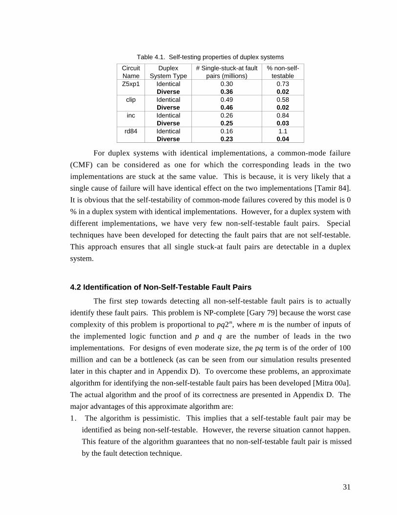
31
Table 4.1. Self-testing properties of duplex systems
CircuitName
DuplexSystem Type
# Single-stuck-at faultpairs (millions)
% non-self-testable
Z5xp1 Identical 0.30 0.73Diverse 0.36 0.02
clip Identical 0.49 0.58Diverse 0.46 0.02
inc Identical 0.26 0.84Diverse 0.25 0.03
rd84 Identical 0.16 1.1Diverse 0.23 0.04
For duplex systems with identical implementations, a common-mode failure
(CMF) can be considered as one for which the corresponding leads in the two
implementations are stuck at the same value. This is because, it is very likely that a
single cause of failure will have identical effect on the two implementations [Tamir 84].
It is obvious that the self-testability of common-mode failures covered by this model is 0
% in a duplex system with identical implementations. However, for a duplex system with
different implementations, we have very few non-self-testable fault pairs. Special
techniques have been developed for detecting the fault pairs that are not self-testable.
This approach ensures that all single stuck-at fault pairs are detectable in a duplex
system.
4.2 Identification of Non-Self-Testable Fault Pairs
The first step towards detecting all non-self-testable fault pairs is to actually
identify these fault pairs. This problem is NP-complete [Gary 79] because the worst case
complexity of this problem is proportional to pq2m, where m is the number of inputs of
the implemented logic function and p and q are the number of leads in the two
implementations. For designs of even moderate size, the pq term is of the order of 100
million and can be a bottleneck (as can be seen from our simulation results presented
later in this chapter and in Appendix D). To overcome these problems, an approximate
algorithm for identifying the non-self-testable fault pairs has been developed [Mitra 00a].
The actual algorithm and the proof of its correctness are presented in Appendix D. The
major advantages of this approximate algorithm are:
1. The algorithm is pessimistic. This implies that a self-testable fault pair may be
identified as being non-self-testable. However, the reverse situation cannot happen.
This feature of the algorithm guarantees that no non-self-testable fault pair is missed
by the fault detection technique.
32
2. The execution time of the algorithm can be tuned according to the desired level of
accuracy and the availability of resources (e.g., processor time).
3. For the simulated designs, the algorithm achieves significant speedup (several orders
of magnitude) compared to exact techniques using Automatic Test Pattern Generation
(ATPG) techniques. Moreover, there is no significant degradation in accuracy
compared to results obtained from an exact technique.
4. The algorithm is flexible so that preprocessing steps can be incorporated to achieve
further speed-ups and higher accuracy of results.
In the next section, we describe test point insertion techniques so that non-self-
testable fault pairs become self-testable [Mitra 00a].
4.3 Self-Testability Enhancement Using Test Points
In the literature on digital testing, test points have been used to enhance fault-
coverage of logic circuits [Eichelberger 83, Abramovici 90, Touba 96]. In this section,
test point insertion techniques are used to enhance the self-testability of duplex systems.
There are two types of test points: control test points and observation test points. In Sec.
4.3.1 and 4.3.2, self-testability enhancement techniques using control and observation test
points, respectively, are described.
4.3.1 Control Test Points
Consider the duplex system consisting of two identical modules with each
implementing the logic circuit shown in Fig. 4.1a. Consider the fault pair in which the
signal line corresponding to Z1 is stuck-at-0 in both modules. It is obvious that the
duplex system will never produce any mismatch signal in the presence of these two
faults. Thus, the fault pair is not self-testable. Next, suppose that for one of the two
modules, we add test points T1 and T2 as shown in Fig. 4.1b. When T1 = 0 and T2 = 0
and a test pattern for Z1 stuck-at-0 (w = 1, x = 1 and y = 0) is applied, a mismatch signal
will be produced if the fault pair is not present (the reverse of the usual situation). If the
fault pair is present, no mismatch signal will be produced. This observation can be used
to detect the presence of the fault pair. A similar case arises when the fault pair Z1 is
stuck-at-1 in both the modules. Thus, control test points can enhance the self-testability
of fault pairs in a duplex system. Note that in a duplex system with two identical
implementations as in Fig. 4.1b, the fault pairs affecting the same leads in the two
implementations are not self-testable. Thus, we have to add these test points at each lead
of the circuit in Fig. 4.1a for non-diverse duplex systems.
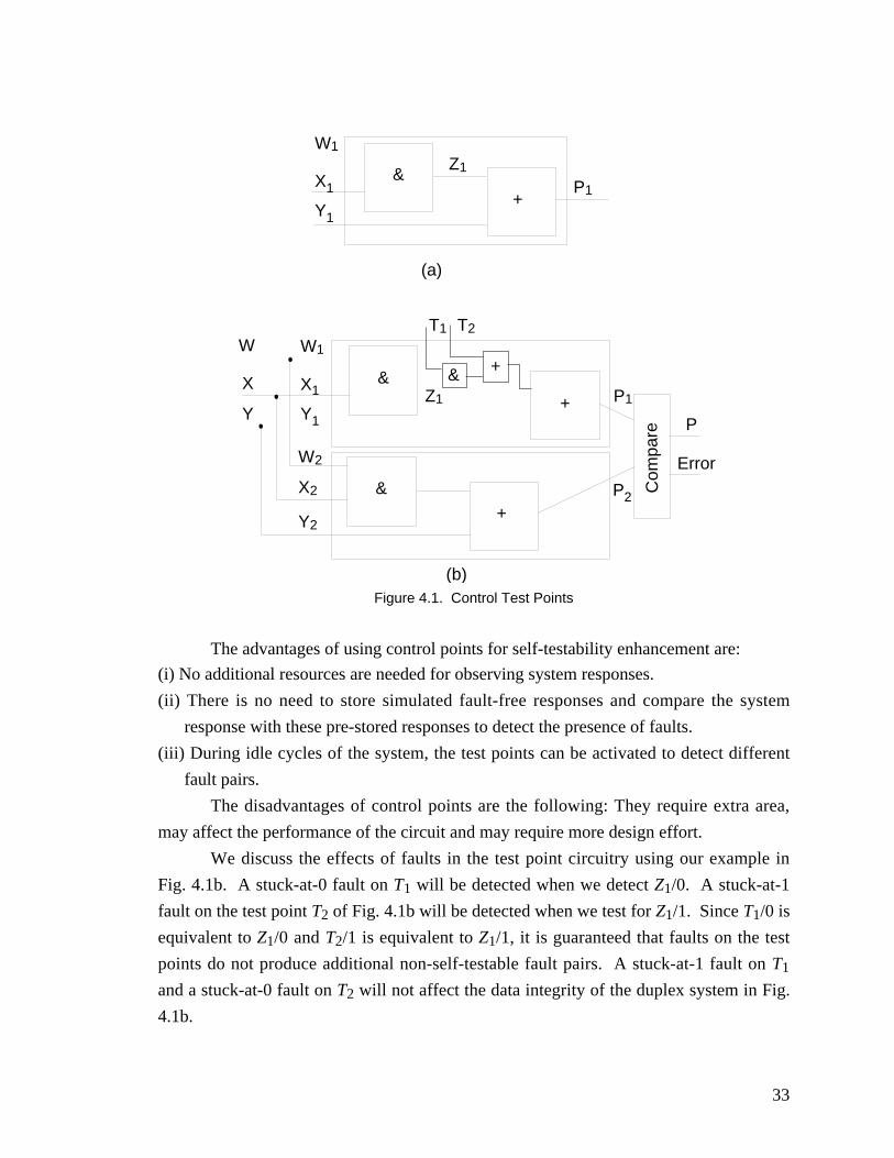
33
&
W1
X1
Y1
Z1
+P1
&
W1
X1
Y1
Z1 +
& +
T1
(a)
T2
&
W2
X2
Y2+
(b)
Com
pare
P1
P2
P
Error
W
X
Y
Figure 4.1. Control Test Points
The advantages of using control points for self-testability enhancement are:
(i) No additional resources are needed for observing system responses.
(ii) There is no need to store simulated fault-free responses and compare the system
response with these pre-stored responses to detect the presence of faults.
(iii) During idle cycles of the system, the test points can be activated to detect different
fault pairs.
The disadvantages of control points are the following: They require extra area,
may affect the performance of the circuit and may require more design effort.
We discuss the effects of faults in the test point circuitry using our example in
Fig. 4.1b. A stuck-at-0 fault on T1 will be detected when we detect Z1/0. A stuck-at-1
fault on the test point T2 of Fig. 4.1b will be detected when we test for Z1/1. Since T1/0 is
equivalent to Z1/0 and T2/1 is equivalent to Z1/1, it is guaranteed that faults on the test
points do not produce additional non-self-testable fault pairs. A stuck-at-1 fault on T1
and a stuck-at-0 fault on T2 will not affect the data integrity of the duplex system in Fig.
4.1b.
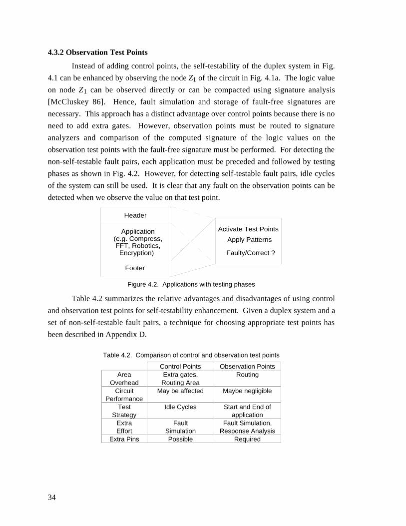
34
4.3.2 Observation Test Points
Instead of adding control points, the self-testability of the duplex system in Fig.
4.1 can be enhanced by observing the node Z1 of the circuit in Fig. 4.1a. The logic value
on node Z1 can be observed directly or can be compacted using signature analysis
[McCluskey 86]. Hence, fault simulation and storage of fault-free signatures are
necessary. This approach has a distinct advantage over control points because there is no
need to add extra gates. However, observation points must be routed to signature
analyzers and comparison of the computed signature of the logic values on the
observation test points with the fault-free signature must be performed. For detecting the
non-self-testable fault pairs, each application must be preceded and followed by testing
phases as shown in Fig. 4.2. However, for detecting self-testable fault pairs, idle cycles
of the system can still be used. It is clear that any fault on the observation points can be
detected when we observe the value on that test point.
Header
Application (e.g. Compress, FFT, Robotics, Encryption)
Activate Test Points
Apply Patterns
Faulty/Correct ?
Footer
Figure 4.2. Applications with testing phases
Table 4.2 summarizes the relative advantages and disadvantages of using control
and observation test points for self-testability enhancement. Given a duplex system and a
set of non-self-testable fault pairs, a technique for choosing appropriate test points has
been described in Appendix D.
Table 4.2. Comparison of control and observation test points
Control Points Observation PointsArea
OverheadExtra gates,Routing Area
Routing
CircuitPerformance
May be affected Maybe negligible
TestStrategy
Idle Cycles Start and End ofapplication
ExtraEffort
FaultSimulation
Fault Simulation,Response Analysis
Extra Pins Possible Required
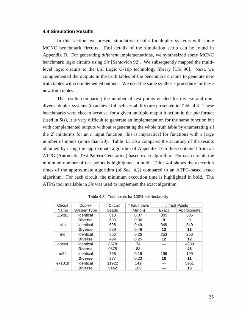
35
4.4 Simulation Results
In this section, we present simulation results for duplex systems with some
MCNC benchmark circuits. Full details of the simulation setup can be found in
Appendix D. For generating different implementations, we synthesized some MCNC
benchmark logic circuits using Sis [Sentovich 92]. We subsequently mapped the multi-
level logic circuits to the LSI Logic G-10p technology library [LSI 96]. Next, we
complemented the outputs in the truth tables of the benchmark circuits to generate new
truth tables with complemented outputs. We used the same synthesis procedure for these
new truth tables.
The results comparing the number of test points needed for diverse and non-
diverse duplex systems (to achieve full self-testability) are presented in Table 4.3. These
benchmarks were chosen because, for a given multiple-output function in the pla format
(used in Sis), it is very difficult to generate an implementation for the same function but
with complemented outputs without regenerating the whole truth table by enumerating all
the 2n minterms for an n input function; this is impractical for functions with a large
number of inputs (more than 20). Table 4.3 also compares the accuracy of the results
obtained by using the approximate algorithm of Appendix D to those obtained from an
ATPG (Automatic Test Pattern Generation) based exact algorithm. For each circuit, the
minimum number of test points is highlighted in bold. Table 4.4 shows the execution
times of the approximate algorithm (of Sec. 4.2) compared to an ATPG-based exact
algorithm. For each circuit, the minimum execution time is highlighted in bold. The
ATPG tool available in Sis was used to implement the exact algorithm.
Table 4.3. Test points for 100% self-testability
Circuit Duplex # Circuit # Fault pairs # Test PointsName System Type Leads (Million) Exact ApproximateZ5xp1 Identical 610 0.37 305 305
Diverse 590 0.36 9 9clip Identical 698 0.49 349 349
Diverse 659 0.46 13 13inc Identical 506 0.26 253 253
Diverse 494 0.25 12 12apex4 Identical 8578 74 — 4289
Diverse 9675 83 — 46rd84 Identical 398 0.16 199 199
Diverse 577 0.23 10 11ex1010 Identical 11922 142 — 5961
Diverse 9142 109 — 15
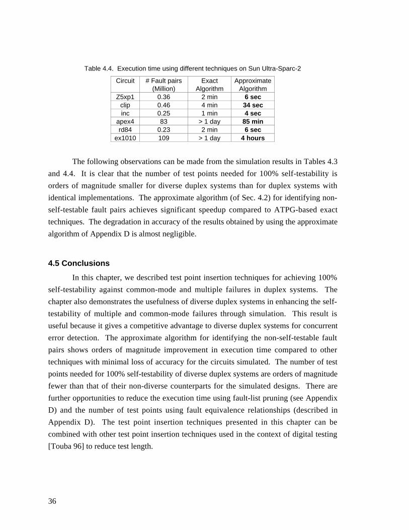
36
Table 4.4. Execution time using different techniques on Sun Ultra-Sparc-2
Circuit # Fault pairs(Million)
ExactAlgorithm
ApproximateAlgorithm
Z5xp1 0.36 2 min 6 secclip 0.46 4 min 34 secinc 0.25 1 min 4 sec
apex4 83 > 1 day 85 minrd84 0.23 2 min 6 sec
ex1010 109 > 1 day 4 hours
The following observations can be made from the simulation results in Tables 4.3
and 4.4. It is clear that the number of test points needed for 100% self-testability is
orders of magnitude smaller for diverse duplex systems than for duplex systems with
identical implementations. The approximate algorithm (of Sec. 4.2) for identifying non-
self-testable fault pairs achieves significant speedup compared to ATPG-based exact
techniques. The degradation in accuracy of the results obtained by using the approximate
algorithm of Appendix D is almost negligible.
4.5 Conclusions
In this chapter, we described test point insertion techniques for achieving 100%
self-testability against common-mode and multiple failures in duplex systems. The
chapter also demonstrates the usefulness of diverse duplex systems in enhancing the self-
testability of multiple and common-mode failures through simulation. This result is
useful because it gives a competitive advantage to diverse duplex systems for concurrent
error detection. The approximate algorithm for identifying the non-self-testable fault
pairs shows orders of magnitude improvement in execution time compared to other
techniques with minimal loss of accuracy for the circuits simulated. The number of test
points needed for 100% self-testability of diverse duplex systems are orders of magnitude
fewer than that of their non-diverse counterparts for the simulated designs. There are
further opportunities to reduce the execution time using fault-list pruning (see Appendix
D) and the number of test points using fault equivalence relationships (described in
Appendix D). The test point insertion techniques presented in this chapter can be
combined with other test point insertion techniques used in the context of digital testing
[Touba 96] to reduce test length.
37
Chapter 5
Combinational Logic Synthesis Techniques for Diversity
One of the major advantages of the diversity metric, introduced in Chapter 2, is
that it can be used to compare two diverse duplex systems quantitatively using the metric.
This aspect of the design diversity metric was covered in Chapter 2. Another potential
advantage of the metric is its use as a cost function in synthesis tools to synthesize two
diverse implementations of the same logic function. Logic synthesis techniques can be
developed to synthesize two implementations in order to maximize the diversity cost
function (while performing optimizations for other cost functions like area, delay, power,
etc., depending on the application). This provides a new dimension to the conventional
synthesis problems.
In this chapter, a systematic procedure is developed to synthesize combinational
logic circuits in order to maximize the diversity among them. Appendix E presents a
complete description of the procedure along with the relevant theorems and proofs.
While the primary focus of this chapter is on combinational logic circuits, the ideas
presented can be extended for sequential circuits. Given the specification of a sequential
logic circuit and an encoding of the internal states, the problem of synthesizing the
sequential circuit can be mapped to a combinational logic synthesis problem. However,
if we have the freedom to choose internal state encoding, then diversity can be created by
encoding the internal states in different ways. This problem is outside the scope of this
chapter.
5.1 Problem Formulation
The input to the problem is the truth table of a combinational circuit to beimplemented and one implementation (N1) of the combinational circuit. The goal is to
synthesize another implementation (N2) of the same combinational circuit such that the
expected data-corruption latency (defined in Chapter 2) of the worst-case fault pairs is
maximized. The expected data-corruption latency of the worst-case fault pairs iscalculated in the following way. For each fault f1 in N1, fault f2 in N2 with the minimum
value of d1,2 is identified (The definition of d1,2 for a fault pair (f1, f2) was introduced in
Chapter 2). The fault pair (f1, f2) is a worst-case fault pair (explained in Chapter 2) and
38
the data-corruption latency of this fault pair is min(T, 1
1 1 2( ),− d), where T is the mission
time of the system. The derivation of the expression for the data corruption latency is
presented in Appendix B and follows from the expression for the expectation of ageometric distribution with parameter (1-d1,2). In the expression for data corruption
latency, we need T because the data corruption latency is theoretically infinite when d1,2
is equal to 1. The objective in this chapter is to maximize the expected value of the data-
corruption latencies of the worst-case fault pairs. Note that, if we want to maximize thedata-corruption latency, then we must minimize (1-d1,2) which means that we must
maximize d1,2. Thus, maximizing the worst-case data-corruption latency is synonymous
to maximizing the diversity of the worst-case fault pairs — hence, we will use both these
terms interchangeably in this chapter.
Conventional logic synthesis techniques consist of two steps: (i) two-level
minimization [McCluskey 56][Brayton 84] followed by (ii) the application of multi-level
transformations [Rajski 92][De Micheli 94]. In this chapter, the same flow will befollowed for synthesizing implementation N2.
5.2 Two-level Logic Synthesis
The first important observation about synthesis of diverse implementations has
been formalized in Theorem 1 of Appendix E. The theorem states that for single-outputfunctions, any two-level logic implementation for N2 will produce the same expected
data-corruption latency for the worst-case fault pairs. Thus, for single-output logic
functions, there is not enough scope to increase the diversity cost function through logic
synthesis.
The proof of Theorem 1 stated above provides a deep insight into the root of the
problem under consideration. It immediately follows from the proof that the amount of
sharing of logic gates among different output functions is the key to achieving high
values of the diversity cost function. For two-level logic implementations, the amount of
sharing of logic gates directly translates to the fanout structure of the implementation.Thus, the fanout structure of the given implementation N1 must be analyzed so that
implementation N2 can be synthesized with sufficient diversity in the fanout structure.
For two-level multiple output logic circuits, the amount of logic sharing (and
hence, the fanout structure) can be controlled during logic synthesis. The conventional
algorithm for two-level synthesis of multi-output logic functions [McCluskey 86] is an
extension of the classical Quine-McCluskey two-level logic minimization procedure
39
[McCluskey 56]. In Appendix E, the conventional two-level synthesis technique for
multiple-output logic functions has been extended to synthesize logic circuits with
maximum diversity and minimal area.
The new algorithm consists of three major steps: (i) Multiple-Output Prime
Iimplicant (MOPI) generation, (ii) Construction of the MOPI Covering Table and (iii)
Choosing a set of MOPIs to cover all the minterms of the given logic functions. The first
two steps of the new algorithm are exactly the same as those in the conventional logic
minimization technique. However, while performing the MOPI covering in the third
step, some extra processing has to be done in order to find the worst-case fault pairs and
calculate the expected data-corruption latency of the worst-case fault pairs. This extra
processing is needed to compute the diversity cost function that must be maximized. The
area cost function computation remains the same as in the conventional algorithm.
Section 6.1 of Appendix E provides a detailed description of the cost function
computation during MOPI covering.
The important features of the new algorithm are:
• The basic steps followed by conventional two-level logic synthesis technique are not
altered. Thus, there is no major change in the synthesis flow.
• The data-structures used by the new technique are almost the same as those used by
the conventional technique.
• All the information needed for calculating the diversity cost function can be derived
from the existing data-structures (which are also used by the conventional technique).
• The algorithm is exact and produces optimal results (maximized diversity, minimized
area). This may be computationally intensive for practical circuits; however,
heuristic techniques can be developed to reduce the complexity. Thus, the new
algorithm can be easily incorporated in any synthesis tool that uses the exact or
approximate forms of the conventional technique.
• The computations associated with the diversity cost function calculation are
extremely simplified if the given truth table with complemented outputs issynthesized for the implementation of N2. Hence, for synthesizing N2, our algorithm
uses the truth table with complemented outputs.
The entire procedure, together with examples, is described in detail in Appendix
E.
40
5.3 Multi-level Logic Synthesis
The conventional techniques for synthesis of multi-level logic circuits rely on a
set of logic transformations that are applied systematically to the input Boolean network
to obtain a final network. Since the multi-level transformations change the structure of
the Boolean network under consideration, they can potentially increase or decrease the
degree of diversity between two logic networks. Hence, it is important to examine the
effects of these transformations on a Boolean network as far as its diversity with respect
to a given Boolean network is concerned.
There are mainly five types of transformations that are used during multi-level
logic synthesis. These are: (i) Single-cube extraction, (ii) Double-cube extraction, (iii)
Re-substitution, (iv) Elimination and (v) Simplification. These transformations are also
included in the widely used rugged script that is provided by the Sis [Sentovich 92] logic
optimization system. Definitions for these transformation functions can be obtained from
[Rajski 92][De Micheli 94]. For most of the cases, the definitions in [Rajski 92] will be
followed in this chapter.
The basic objective in this section is to identify a set of multi-level logic
transformations that can be used safely without decreasing the diversity cost function
obtained from two-level synthesis. It is thus guaranteed that the application of any
sequence of these transformations preserves the value of the diversity cost function (and
hence the gains from diversity) which was maximized during two-level logic synthesis.
This idea is somewhat (but not fully) similar to the notion of testability preserving
transformations that are used by synthesis-for-testability techniques [Devadas 92][Rajski
92].
It may be noted that by applying some of these transformations the diversity cost
function can actually be increased. This observation leads to interesting optimization
problems that are outside the scope of this chapter.
5.3.1 Single-Cube Extraction
“Single-cube extraction is the process of extracting cubes which are common to
two or more cubes” [Rajski 92]. For example, let us suppose that we have a logic
function f = abA1 + abA2 + … + abAn. When single-cube extraction is performed, we
have an intermediate node (AND gate) C = ab and f = CA1 + CA2 + … + CAn. Figure 5.1
illustrates this procedure. It is shown in Appendix E that the application of single-cubeextraction on a logic network K to obtain a new implementation for N2 does not change
the expected worst-case data-corruption latency of the duplex system. Hence, the
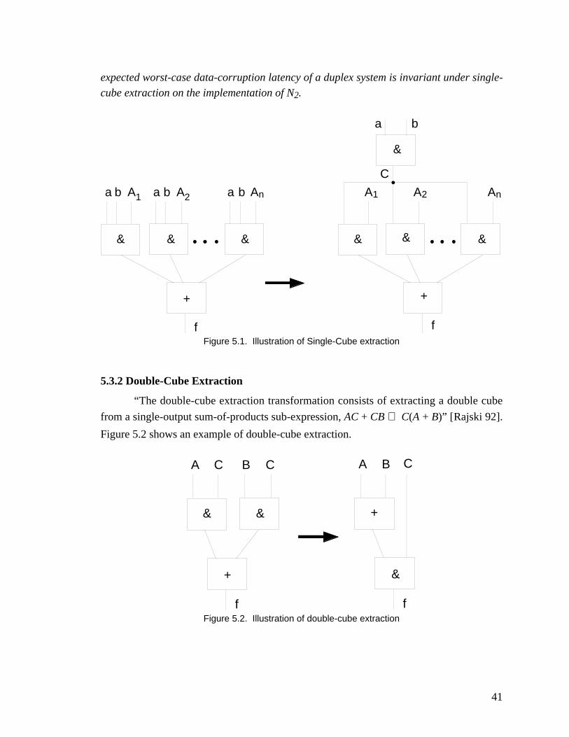
41
expected worst-case data-corruption latency of a duplex system is invariant under single-
cube extraction on the implementation of N2.
a b A1 a b A2 a b An
& & &
+
A1 A2 An
& & &
+
a b
&
C
f fFigure 5.1. Illustration of Single-Cube extraction
5.3.2 Double-Cube Extraction
“The double-cube extraction transformation consists of extracting a double cube
from a single-output sum-of-products sub-expression, AC + CB ⇒ C(A + B)” [Rajski 92].
Figure 5.2 shows an example of double-cube extraction.
A C B C
& &
+
f
A B
+
&
f
C
Figure 5.2. Illustration of double-cube extraction
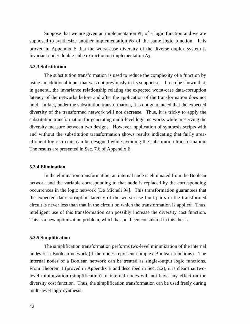
42
Suppose that we are given an implementation N1 of a logic function and we are
supposed to synthesize another implementation N2 of the same logic function. It is
proved in Appendix E that the worst-case diversity of the diverse duplex system isinvariant under double-cube extraction on implementation N2.
5.3.3 Substitution
The substitution transformation is used to reduce the complexity of a function by
using an additional input that was not previously in its support set. It can be shown that,
in general, the invariance relationship relating the expected worst-case data-corruption
latency of the networks before and after the application of the transformation does not
hold. In fact, under the substitution transformation, it is not guaranteed that the expected
diversity of the transformed network will not decrease. Thus, it is tricky to apply the
substitution transformation for generating multi-level logic networks while preserving the
diversity measure between two designs. However, application of synthesis scripts with
and without the substitution transformation shows results indicating that fairly area-
efficient logic circuits can be designed while avoiding the substitution transformation.
The results are presented in Sec. 7.6 of Appendix E.
5.3.4 Elimination
In the elimination transformation, an internal node is eliminated from the Boolean
network and the variable corresponding to that node is replaced by the corresponding
occurrences in the logic network [De Micheli 94]. This transformation guarantees that
the expected data-corruption latency of the worst-case fault pairs in the transformed
circuit is never less than that in the circuit on which the transformation is applied. Thus,
intelligent use of this transformation can possibly increase the diversity cost function.
This is a new optimization problem, which has not been considered in this thesis.
5.3.5 Simplification
The simplification transformation performs two-level minimization of the internal
nodes of a Boolean network (if the nodes represent complex Boolean functions). The
internal nodes of a Boolean network can be treated as single-output logic functions.
From Theorem 1 (proved in Appendix E and described in Sec. 5.2), it is clear that two-
level minimization (simplification) of internal nodes will not have any effect on the
diversity cost function. Thus, the simplification transformation can be used freely during
multi-level logic synthesis.
43
5.4 Conclusions
In this chapter, for the first time, techniques have been developed to synthesize
diverse implementations of combinational logic circuits for duplex systems so that the
advantages obtained from using diverse implementations are maximized. Unlike
previous approaches for designing diverse implementations that depended on
independent generation, a concrete diversity cost function has been identified. A two-
level logic synthesis procedure to maximize the diversity of the cost function without
drastically affecting the area cost function has been described. Multi-level logic
transformations that can be applied without affecting diversity in the resulting logic
structure have also been identified in this chapter. New optimization problems involving
the maximization of the diversity cost function during multi-level synthesis have also
been formulated. Future research in this area must focus on identifying new multi-level
logic transformations that can maximize the diversity cost function while minimizing the
area/delay/power-consumption of the resulting implementation.
44
Chapter 6
Common-Mode Failure Models and Redundant SystemDesign
This chapter introduces fault models for CMFs in digital redundant systems and
presents techniques for designing redundant systems with guaranteed data integrity
against modeled CMFs. A detailed description of the topics discussed in this chapter can
be obtained from Appendix F and Appendix G.
6.1 Common-Mode Fault Models
Consider a redundant system with separate input registers associated with each
module of the system. In such a system, consider the class of failures, in the presence of
which, the same bit positions in two or more input registers are stuck at the same value.
In classical redundant systems, these failures will have identical effects on all the
implementations and will go undetected when producing incorrect outputs. Hence, these
failures are possible CMF candidates. These CMFs are called Input-Register-Common-
Mode-Failures and the corresponding fault model is called Input-Register-CMF Model-1
(IR-CMF-1). This fault model includes transient faults from radiation upsets, permanent
faults that result from permanent system interference caused by the operational
environment, and some design weaknesses that can be caused due to design faults. An
analysis of the possible failure modes covered by this fault model is presented in
Appendix G.
As mentioned in Appendix G, the CMF model IR-CMF-1 is mainly suitable for
digital designs containing register-files. However, not all designs contain register-files
and the IR-CMF-1 model must be extended. Under the extended fault model, called IR-
CMF-2, the constraint that only the corresponding bit-positions of the input registers can
be stuck at the same value is relaxed. For example, in the presence of IR-CMF-2 in a
duplex system, the second bit position of the input register of the first module and the
fifth bit position of the input register of the second module may be stuck at same or
different values at the same time. IR-CMF-2 is a generalized version of IR-CMF-1. A
motivating factor and the explanation of possible scenarios in which IR-CMF-2 should be
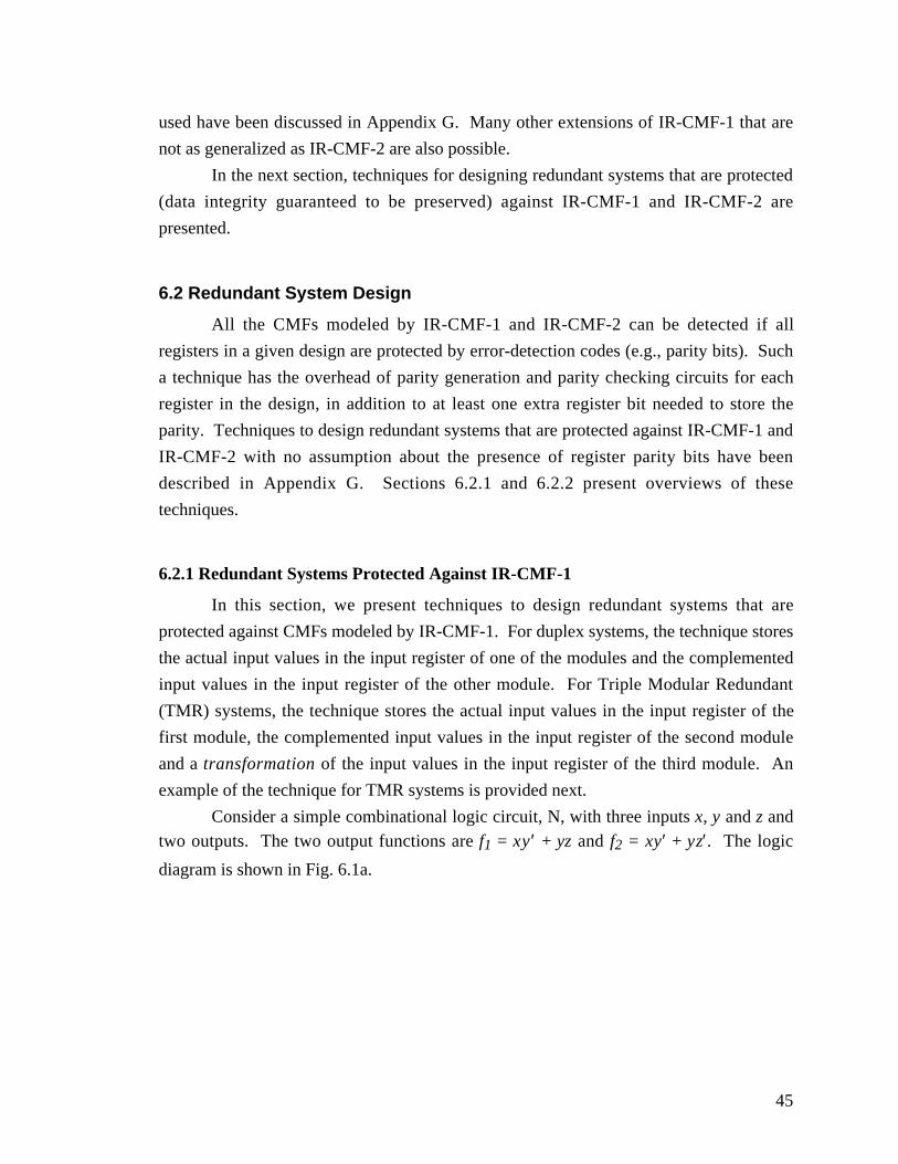
45
used have been discussed in Appendix G. Many other extensions of IR-CMF-1 that are
not as generalized as IR-CMF-2 are also possible.
In the next section, techniques for designing redundant systems that are protected
(data integrity guaranteed to be preserved) against IR-CMF-1 and IR-CMF-2 are
presented.
6.2 Redundant System Design
All the CMFs modeled by IR-CMF-1 and IR-CMF-2 can be detected if all
registers in a given design are protected by error-detection codes (e.g., parity bits). Such
a technique has the overhead of parity generation and parity checking circuits for each
register in the design, in addition to at least one extra register bit needed to store the
parity. Techniques to design redundant systems that are protected against IR-CMF-1 and
IR-CMF-2 with no assumption about the presence of register parity bits have been
described in Appendix G. Sections 6.2.1 and 6.2.2 present overviews of these
techniques.
6.2.1 Redundant Systems Protected Against IR-CMF-1
In this section, we present techniques to design redundant systems that are
protected against CMFs modeled by IR-CMF-1. For duplex systems, the technique stores
the actual input values in the input register of one of the modules and the complemented
input values in the input register of the other module. For Triple Modular Redundant
(TMR) systems, the technique stores the actual input values in the input register of the
first module, the complemented input values in the input register of the second module
and a transformation of the input values in the input register of the third module. An
example of the technique for TMR systems is provided next.
Consider a simple combinational logic circuit, N, with three inputs x, y and z andtwo outputs. The two output functions are f1 = xy ′ + yz and f2 = xy′ + yz′ . The logic
diagram is shown in Fig. 6.1a.
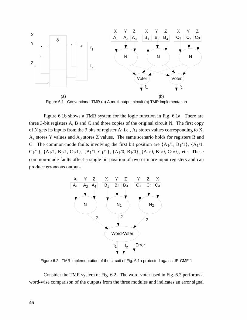
46
X
Y
Z
&
+ f1
f2
(a)
A1 A2 A3 B1 B2 B3 C1 C2 C3
Voter Voter
(b)
N N N
f1 f2
X Y Z X Y Z X Y Z
Figure 6.1. Conventional TMR (a) A multi-output circuit (b) TMR implementation
Figure 6.1b shows a TMR system for the logic function in Fig. 6.1a. There are
three 3-bit registers A, B and C and three copies of the original circuit N. The first copyof N gets its inputs from the 3 bits of register A; i.e., A1 stores values corresponding to X,
A2 stores Y values and A3 stores Z values. The same scenario holds for registers B and
C. The common-mode faults involving the first bit position are {A1/1, B1/1}, {A1/1,
C1/1}, {A1/1, B1/1, C1/1}, {B1/1, C1/1}, {A1/0, B1/0}, {A1/0, B1/0, C1/0}, etc. These
common-mode faults affect a single bit position of two or more input registers and can
produce erroneous outputs.
A1 A2 A3 B1 B2 B3 C1 C2 C3
Word-Voter
N N1 N2
f1 f2
X Y Z X Y Z Y Z X
2 22
Error
Figure 6.2. TMR implementation of the circuit of Fig. 6.1a protected against IR-CMF-1
Consider the TMR system of Fig. 6.2. The word-voter used in Fig. 6.2 performs a
word-wise comparison of the outputs from the three modules and indicates an error signal
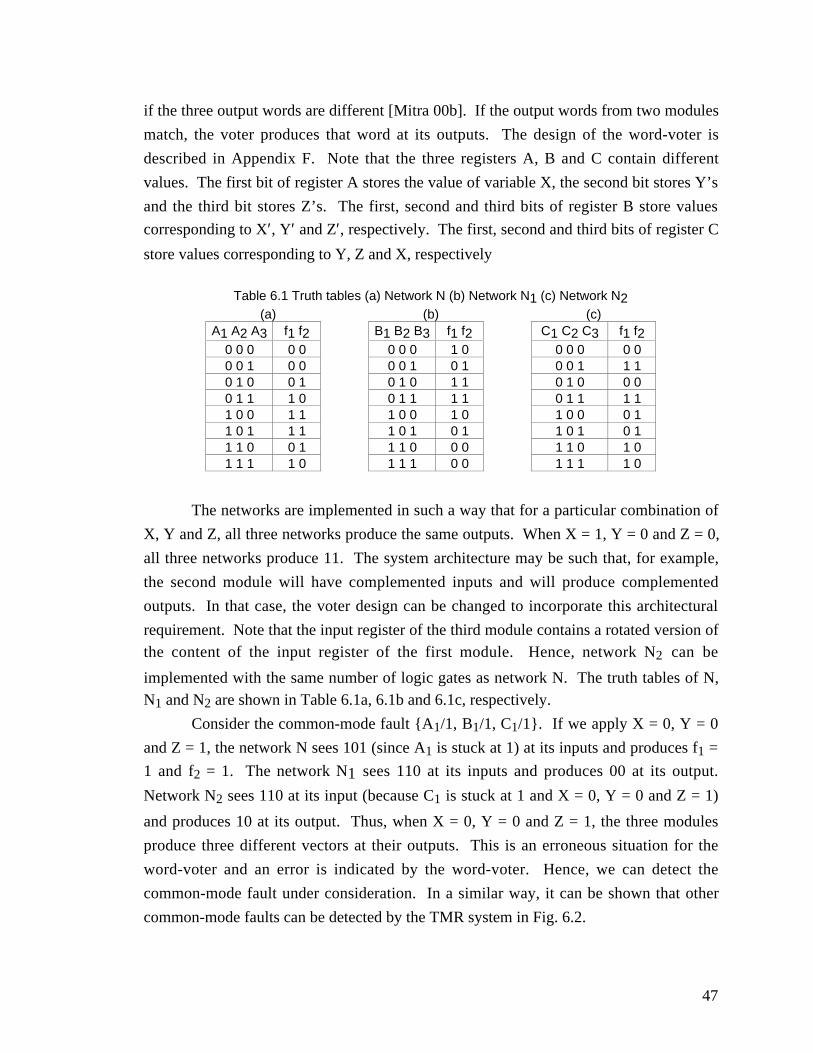
47
if the three output words are different [Mitra 00b]. If the output words from two modules
match, the voter produces that word at its outputs. The design of the word-voter is
described in Appendix F. Note that the three registers A, B and C contain different
values. The first bit of register A stores the value of variable X, the second bit stores Y’s
and the third bit stores Z’s. The first, second and third bits of register B store values
corresponding to X′, Y′ and Z′, respectively. The first, second and third bits of register C
store values corresponding to Y, Z and X, respectively
Table 6.1 Truth tables (a) Network N (b) Network N1 (c) Network N2(a) (b) (c)
A1 A2 A3 f1 f2 B1 B2 B3 f1 f2 C1 C2 C3 f1 f20 0 0 0 0 0 0 0 1 0 0 0 0 0 00 0 1 0 0 0 0 1 0 1 0 0 1 1 10 1 0 0 1 0 1 0 1 1 0 1 0 0 00 1 1 1 0 0 1 1 1 1 0 1 1 1 11 0 0 1 1 1 0 0 1 0 1 0 0 0 11 0 1 1 1 1 0 1 0 1 1 0 1 0 11 1 0 0 1 1 1 0 0 0 1 1 0 1 01 1 1 1 0 1 1 1 0 0 1 1 1 1 0
The networks are implemented in such a way that for a particular combination of
X, Y and Z, all three networks produce the same outputs. When X = 1, Y = 0 and Z = 0,
all three networks produce 11. The system architecture may be such that, for example,
the second module will have complemented inputs and will produce complemented
outputs. In that case, the voter design can be changed to incorporate this architectural
requirement. Note that the input register of the third module contains a rotated version ofthe content of the input register of the first module. Hence, network N2 can be
implemented with the same number of logic gates as network N. The truth tables of N,N1 and N2 are shown in Table 6.1a, 6.1b and 6.1c, respectively.
Consider the common-mode fault {A1/1, B1/1, C1/1}. If we apply X = 0, Y = 0
and Z = 1, the network N sees 101 (since A1 is stuck at 1) at its inputs and produces f1 =
1 and f2 = 1. The network N1 sees 110 at its inputs and produces 00 at its output.
Network N2 sees 110 at its input (because C1 is stuck at 1 and X = 0, Y = 0 and Z = 1)
and produces 10 at its output. Thus, when X = 0, Y = 0 and Z = 1, the three modules
produce three different vectors at their outputs. This is an erroneous situation for the
word-voter and an error is indicated by the word-voter. Hence, we can detect the
common-mode fault under consideration. In a similar way, it can be shown that other
common-mode faults can be detected by the TMR system in Fig. 6.2.
48
In Appendix G, a Boolean Satisfiability technique is developed to obtain the
transformation for the third module so that the data-integrity of the resulting system
against IR-CMF-1 is guaranteed. In Appendix G, it is also proved that for arbitrary logic
networks it is always possible to design TMR systems with full data integrity against IR-
CMF-1 by possibly adding at most one extra output to the implemented logic function.
6.2.2 Redundant Systems Protected Against IR-CMF-2
Since IR-CMF-2 is a generalized version of IR-CMF-1, techniques to design
redundant systems protected against IR-CMF-2 are more complicated than those for IR-
CMF-1. A complete explanation of the entire technique is reported in Appendix G. In
this section, the basic idea behind the technique is illustrated for duplex systems.
However, the whole idea can be extended for TMR systems.
Table 6.2. An example logic function
x y z f1 f20 0 0 0 00 0 1 0 00 1 0 0 10 1 1 1 01 0 0 1 11 0 1 1 11 1 0 0 11 1 1 1 0
Consider the example logic function of Table 6.2. The goal is to design a duplex
system for this logic function, protected against IR-CMF-2. Call the two modules of theduplex system N1 and N2. The first module (N1) of the duplex system is obtained by
normal synthesis of the function — its input register contains the values of x, y and z in
the three flip-flops.For the second module (N2), we want to find a good transformation T of the
inputs of the logic function. The outputs of the network implementing the transformation
T will be connected to the input register of the second module. Finally, the second
module will take inputs from its input register and produce outputs. The scheme is
depicted in Fig. 6.3.
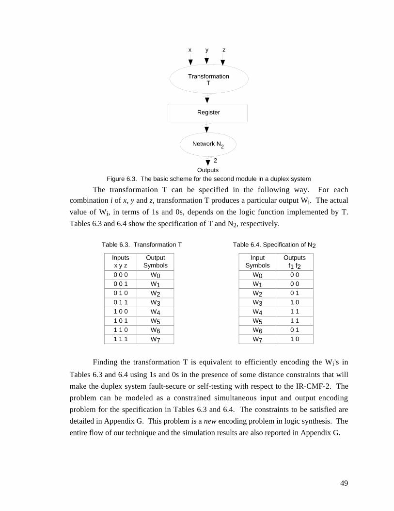
49
Transformation T
x y z
Register
Network N2
2
OutputsFigure 6.3. The basic scheme for the second module in a duplex system
The transformation T can be specified in the following way. For eachcombination i of x, y and z, transformation T produces a particular output Wi. The actual
value of Wi, in terms of 1s and 0s, depends on the logic function implemented by T.
Tables 6.3 and 6.4 show the specification of T and N2, respectively.
Table 6.3. Transformation T Table 6.4. Specification of N2
Inputs Output Input Outputsx y z Symbols Symbols f1 f20 0 0 W0 W0 0 00 0 1 W1 W1 0 00 1 0 W2 W2 0 1
0 1 1 W3 W3 1 01 0 0 W4 W4 1 1
1 0 1 W5 W5 1 11 1 0 W6 W6 0 11 1 1 W7 W7 1 0
Finding the transformation T is equivalent to efficiently encoding the Wi's in
Tables 6.3 and 6.4 using 1s and 0s in the presence of some distance constraints that will
make the duplex system fault-secure or self-testing with respect to the IR-CMF-2. The
problem can be modeled as a constrained simultaneous input and output encoding
problem for the specification in Tables 6.3 and 6.4. The constraints to be satisfied are
detailed in Appendix G. This problem is a new encoding problem in logic synthesis. The
entire flow of our technique and the simulation results are also reported in Appendix G.
50
6.3 Conclusions
The major contributions of this chapter are:
• Two fault models (IR-CMF-1 and IR-CMF-2) have been developed for common-
mode failures.
• IR-CMF-2 is very general and can also be used to model failures in multiple input
registers of redundant systems.
• A new voter design for TMR systems (Appendix F) has been introduced.
• Techniques to design redundant systems protected (guaranteed data integrity or self-
testability) against the modeled CMFs have been described.
• A new encoding problem in logic synthesis has been developed.
51
Chapter 7
Concluding Remarks
In this dissertation, a study has been conducted to quantitatively analyze the
effectiveness of various concurrent error detection (CED) schemes and techniques for
efficient concurrent error detection have been developed.
For the first time, a metric to quantify design diversity in redundant systems is
presented and used for analyzing CED schemes based on diverse duplication. This
analysis technique provides a quantitative definition of design diversity and helps
designers determine design choices by deriving quantitative relationships among
diversity, data integrity, failure rate and mission time. This quantitative analysis also
enables a comparative study of different CED schemes. The study, by means of
simulation experiments and theoretical analysis, concludes that diverse duplication
provides significantly better data integrity against multiple and common-mode failures
(CMFs) compared to other CED schemes.
New fault models for CMFs are proposed and the possible failure mechanisms for
the modeled CMFs are analyzed. New design techniques and synthesis algorithms with
diversity as a cost function have been developed, for the first time, to efficiently design
systems based on diverse duplication.
As mentioned in Chapter 1, noise sources from transients, coupling effects and
soft-errors constitute a major cause of concern for the future nanometer integrated circuit
technologies (0.1µ or smaller) with smaller geometries; this problem has been publicly
acknowledged by leading semiconductor companies. Simple fault-avoidance techniques
(e.g., less aggressive design rules, extra noise margins) may not be effective under such
circumstances. Concurrent error detection can provide a cost-effective solution to
guarantee data integrity in complex VLSI systems in the era of nanometer technologies.
In addition, CED techniques can provide protection against upsets in radiation
environment and can be used as an alternative to expensive fault-avoidance techniques
based on radiation-hardening. With the study presented in this dissertation, it is now
feasible to use cost-effective diverse duplication techniques for efficient concurrent error
detection. This research enables quantification of the effectiveness of design diversity as
a CED technique and allows the user to design diverse implementations with a complete
52
control of the associated trade-offs (e.g., effectiveness during concurrent error detection,
area, delay, power consumption, etc.).
Future research should focus on developing efficient algorithms for applying the
ideas presented in this dissertation for the analysis of large systems (e.g.,
microprocessors, software, etc.) and synthesis techniques for sequential logic circuits
with concurrent error detection based on diverse duplication.
53
Publications from this Dissertation
1. Subhasish Mitra and Edward J. McCluskey, “Which Concurrent Error DetectionScheme to Choose ?”, International Test Conference, 2000, To appear.
2. Subhasish Mitra and Edward J. McCluskey, “Combinational Logic Synthesis forDiversity in Duplex Systems,” International Test Conference, 2000, To appear.
3. Subhasish Mitra, Nirmal R. Saxena and Edward J. McCluskey, "Common-ModeFailures in Redundant VLSI Systems: A Survey," IEEE Transactions on Reliability,2000, Special Section on Fault-Tolerant VLSI Systems, To appear.
4. Subhasish Mitra and Edward J. McCluskey, "WORD VOTER: A New Voter Designfor Triple Modular Redundant Systems," VLSI Test Symposium, pp. 465-470, 2000.
5. Subhasish Mitra, Nirmal R. Saxena and Edward J. McCluskey, "Fault Escapes inDuplex Systems," VLSI Test Symposium, 2000, pp. 453-458, 2000.
6. Nirmal R. Saxena, Santiago-Fernandez Gomez, Wei-je Huang, Subhasish Mitra, Shu-Yi Yu and Edward J. McCluskey, "Dependable Computing and On-Line Testing inAdaptive and Reconfigurable Systems", IEEE Design and Test of Computers, Jan.-March, 2000.
7. Subhasish Mitra, Nirmal R. Saxena and Edward J. McCluskey, "A Design DiversityMetric and Reliability Analysis For Redundant Systems ", International TestConference, pp. 662-671, 1999.
8. Subhasish Mitra, Nirmal R. Saxena and Edward J. McCluskey, "Design Diversity ForRedundant Systems ", Fast Abstract, International Symposium on Fault-TolerantComputing, 1999.
9. Subhasish Mitra and Edward J. McCluskey, “Design of Redundant Systems ProtectedAgainst Common-Mode Failures,” Technical Report, CRC-TR-00-2, Center forReliable Computing, Stanford University, 2000.
10. Subhasish Mitra, Nirmal R. Saxena and Edward J. McCluskey, “Non-Self-TestableFaults in Duplex Systems,” IEEE International Workshop on High-Level DesignValidation and Test, 1999.
54
References
[Abramovici 90] Abramovici, M., M. A. Breuer and A. D. Friedman, Digital systems
testing and testable design, 1990.
[Avizienis 77] Avizienis, A. and L. Chen, "On the implementation of N-version
programming for software fault-tolerance during program execution," Proc. Intl.
Computer Software and Appl. Conf., pp. 149-155, 1977.
[Avizienis 84] Avizienis, A. and J. P. J. Kelly, "Fault Tolerance by Design Diversity:
Concepts and Experiments," IEEE Computer, pp. 67-80, August 1984.
[Berger 61] Berger, J. M., “A Note on Error Detection Codes for Asymmetric
Channels,” Information and Control, Vol. 4, pp. 68-73, 1961.
[Bose 85] Bose, B. and D. J. Lin, “Systematic Unidirectional Error-Detecting Codes,”
IEEE Trans. Computers, pp. 1026-1032, Nov. 1985.
[Brayton 84] Brayton, R. K., et al., Logic Minimization Algorithms for VLSI Synthesis,
Kluwer Academic Publishers, 1984.
[Briere 93] Briere, D. and P. Traverse, “Airbus A320/A330/A340 Electrical Flight
Controls: A family of fault-tolerant systems,” Proc. FTCS, pp. 616-623, 1993.
[Carter 64] Carter, W., et al., “Design of Serviceability Features for the IBM
System/360,” IBM Journal, pp. 115-126, April 1964.
[Carter 77] Carter, W., et al., “Cost Effectiveness of Self-Checking Computer Design,”
Proc. FTCS, pp. 117-123, 1977.
[Chang 96] Chang, J. T-Y and E. J. McCluskey, "SHOrt Voltage Elevation (SHOVE)
Test," Proc. Intl. Test Conference, pp. 45-49, 1996.
[Chen 78] Chen, L. and A. Avizienis, “N-Version Programming: A Fault-Tolerance
Approach to Reliability of Software Operation,” Proc. FTCS, pp. 3-9, 1978.
[Chen 92] Chen, C. L., et al., “Fault-tolerance Design of the IBM Enterprise
System/9000 Type 9021 Processors,” IBM Journal Res. and Dev., Vol. 36, No. 4, pp.
765-779, July 1992.
[Collier 99] Collier, C. P., et al., “Electronically Configurable Molecular-Based Logic
Gates,” Science, Vol. 285, No. 5426, pp. 391-394, July 1999.
[De 94] De, K., C. Natarajan, D. Nair and P. Banerjee, “RSYN: A System for Automated
Synthesis of Reliable Multilevel Circuits,” IEEE Trans. VLSI, Vol. 2, pp. 186-195, June
1994.
55
[De Micheli 94] De Micheli, G., Synthesis and Optimization of Digital circuits,
McGraw-Hill, 1994.
[Devadas 92] Devadas, S., and K. Keutzer, “Synthesis of Robust Delay-Fault Testable
Circuits: Theory,” IEEE Trans. CAD, Vol. 11, No. 1, pp. 87-101, January 1992.
[EE Times 99] “Intel Scans for Soft Errors in Processor Designs,” EE Times
(Semiconductors), June 1999.
[Eichelberger 83] Eichelberger, E. B. and E. Lindbloom, “Random-Pattern Coverage
Enhancement and Diagnosis for LSSD Logic Self-Test,” IBM Journal of Res. and Dev.,
Vol. 27, No. 3, pp. 265-272, May 1983.
[Gary 79] Gary, M. and D. Johnson, Computers and Intractability: A Guide to the
Theory of NP-Completeness, W. H. Freeman and Company, 1979.
[Gulati 93] Gulati, R. K., and C. F. Hawkins, Iddq Testing of VLSI Circuits, Kluwer
Academic Publishers, 1993.
[Hao 93] Hao, H and E. J. McCluskey, "Very-Low-Voltage Testing for Weak CMOS
Logic ICs," Proc. Intl. Test Conference, pp. 275-284, 1993.
[Hennessy 99] Hennessy, J., “The Future of Systems Research,” IEEE Computer, Vol.
32, No. 8, pp. 27-33, August 1999.
[Hnatek 95] Hnatek, E. R., Integrated Circuit Quality and Reliability, 1995.
[Hsiao 81] Hsiao, M-Y, W. C. Carter, J. W. Thomas and W. R. Stringfellow,
“Reliability, Availability and Serviceability of IBM Computer Systems: A Quarter
Century of Progress,” IBM Journal of Research and Development, Vol. 25, No. 5, pp.
453-469, Sept. 1981.
[Huang 84] Huang, K. H. and J. A. Abraham, “Algorithm-based fault tolerance for
matrix operations,” IEEE Trans. Computers, Vol. C-33, No. 6, pp. 518-528, June 1984.
[Hughes 84] Hughes, J. L., E. J. McCluskey and D. J. Lu, “Design of Totally Self-
Checking Comparators with an Arbitrary Number of Inputs,” IEEE Trans. Computers,
Vol. C-33, No.6, pp. 546-50, June 1984.
[Jacobs 70] Jacobs, I. M., "The Common Mode Failure Study Discipline," IEEE Trans.
Nuclear Science, Vol. 17, No. 1, pp. 594-598, February 1970.
[Jha 93] Jha, N. K. and S. J. Wang, “Design and Synthesis of Self-Checking VLSI
Circuits,” IEEE Trans. CAD, Vol. 12, pp. 878-887, June 1993.
[Kraft 81] Kraft, G. D. and W. N. Toy, Microprogrammed Control and Reliable Design
of Small Computers, Prentice Hall, 1981.
[Lala 94] Lala, J. H. and R. E. Harper, "Architectural Principles for Safety-Critical Real-
Time Applications," Proc. of the IEEE, Vol. 82, No. 1, pp. 25-40, 1994.
56
[Littlewood 96] Littlewood, B., "The impact of diversity upon common mode failures,"
Reliability Engineering and System Safety, Vol. 51, No. 1, pp. 101-113, 1996.
[Mahmood 84] Mahmood, A., D. M. Andrews and E. J. McCluskey, “Executable
Assertions and Flight Software,” Proc. AIAA/IEEE Digital Avionics Systems, Conf., pp.
346-351, 1984.
[Marouf 78] Marouf, M. A. and A. D. Friedman, “Design of Self-checking Checkers for
Berger Codes,” Proc. FTCS, pp. 179-184, 1978.
[McCluskey 56] McCluskey, E.J., “Minimization of Boolean Functions,” Bell System
Tech. Journal, Vol. 35, No. 5, pp. 1417-1444, Nov. 1956.
[McCluskey 85] McCluskey, E. J., “Hardware Fault Tolerance,” Proc. COMPCON85,
pp. 260-263, 1985.
[McCluskey 86] McCluskey, E. J., Logic Design Principles with Emphasis on Testable
Semicustom Circuits, Prentice-Hall, Eaglewood Cliffs, NJ, USA, 1986.
[McCluskey 88] McCluskey, E. J., S. Makar, S. Mourad and K. D. Wagner, “Probability
Models for Pseudo-random Test Sequences,” IEEE Trans. Computers, Vol. 37, No. 2, pp.
160-174, Feb. 1988.
[McCluskey 90] McCluskey, E. J., “Design techniques for Testable Embedded Error
Checkers,” IEEE Computer, Vol. 23, No. 7, pp. 84-88, July 1990.
[Mitra 99a] Mitra, S., N. R. Saxena and E. J. McCluskey, “A Design Diversity Metric
and Reliability Analysis of Redundant Systems,” Proc. IEEE Intl. Test Conf., pp. 662-
671, 1999.
[Mitra 99b] Mitra, S., N. R. Saxena and E. J. McCluskey, “A Design Diversity Metric
and Analysis of Redundant Systems,” Technical Report, Center for Reliable Computing,
Stanford Univ., CRC-TR-99-4, 1999.
[Mitra 00a] Mitra, S., N. R. Saxena and E. J. McCluskey, “Fault Escapes in Duplex
Systems,” Proc. IEEE VLSI Test Symp., pp. 453-458, 2000.
[Mitra 00b] Mitra, S., and E. J. McCluskey, “Word-Voter: A New Voter Design for
Triple Modular Redundant Systems,” Proc. IEEE VLSI Test Symp., pp. 465-470, 2000.
[Mitra 00c] Mitra, S., N. R. Saxena and E. J. McCluskey, “Common-Mode Failures in
Redundant VLSI Systems: A Survey,” IEEE Trans. Reliability, Special Section on Fault-
Tolerant VLSI Systems, 2000, To appear.
[Needham 91] Needham, W, Designer's guide to testable ASIC devices, 1991.
[Nicolaidis 93] Nicolaidis, M., “Efficient Implementations of Self-Checking Adders and
ALUs,” Proc. International Symp. Fault-Tolerant Computing, pp. 586-595, 1993.
[Peterson 00] Peterson, C., “Taking Technology to the Molecular Level,” IEEE
Computer, Vol. 33, No. 1, pp. 46-53, Jaunary 2000.
57
[Pradhan 96] Pradhan, D. K., Fault-Tolerant Computer System Design, Prentice Hall,
1996.
[Quinlan 99] Quinlan, T., “New Era in Chip Design,” San Jose Mercury News, July 10,
1999.
[Rajski 92] Rajski, J. and J. Vasudevamurthy, “The testability-preserving concurrent
decomposition and factorization of Boolean expressions,” IEEE Trans. CAD, Vol. 11,
No. 6, pp. 778-793, June 1992.
[Reed 97] Reed, R., et al., “Heavy ion and proton-induced single event multiple upset,”
IEEE Trans. Nuclear Science, Vol. 44, No. 6, pp. 2224-2229, July 1997.
[Riter 95] Riter, R., "Modeling and Testing a Critical Fault-Tolerant Multi-Process
System," Proc. FTCS, pp. 516-521, 1995.
[Saxena 00] Saxena, N. R., et al., “Dependable Computing and On-Line Testing in
Adaptive and Reconfigurable Systems,” IEEE Design and Test of Computers, Jan-Mar.
2000.
[Sedmak 78] Sedmak, R. M. and H. L. Liebergot, “Fault-Tolerance of a General-Purpose
Computer Implemented by Very Large Scale Integration,” Proc. FTCS, pp. 137-143,
1978.
[Sellers 68] Sellers, F., M-Y Hsiao and L. W. Bearnson, Error Detection Logic for
Digital Computers, McGraw-Hill Book Company, 1968.
[Sentovich 92] Sentovich, E. M., et al., “SIS: A System for Sequential Circuit
Synthesis,” ERL Memo. No. UCB/ERL M92/41, EECS, UC Berkeley, CA 94720.
[Shedletsky 76] Shedletsky, J.J., and E.J. McCluskey, "The Error Latency of a Fault in a
Sequential Digital Circuit," IEEE Trans. Computers, C-25, No. 6, pp. 655-659, June
1976.
[Siewiorek 92] Siewiorek, D. P. and R. S. Swarz, Reliable Computer Systems: Design
and Evaluation, Digital Press, 1992.
[Tamir 84] Tamir, Y. and C. H. Sequin, "Reducing common mode failures in duplicate
modules," Proc. IEEE Intl. Conf. on Computer Design, pp.302-307, 1984.
[Touba 96] Touba, N.A., and E.J. McCluskey, “Test Point Insertion Based on Path
Tracing,” Proc. VLSI Test Symp., pp. 2-8, 1996.
[Touba 97] Touba, N. A. and E. J. McCluskey, “Logic Synthesis of Multilevel Circuits
with Concurrent Error Detection,” IEEE Trans. CAD, Vol. 16, pp. 783-789, July 1997.
[Wall Street 99] “HP Researchers Shrink Chips to Molecule Size,” The Wall Street
Journal, July 16, 1999.
[Wakerly 78] Wakerly, J., Error Detecting Codes, Self-checking Circuits and
Applications, North Holland, 1978.
58
[Watson 79] Watson, I. A. and G. T. Edwards, "Common-Mode Failures In Redundancy
Systems," Nuclear technology, Vol. 46, pp. 183-191, December 1979.
[Webb 97] Webb, C. F., and J. S. Liptay, “A High Frequency Custom S/390
Microprocessor,” IBM Journal of Research and Development, Vol. 41, No. 4/5, pp. 463-
474, July/Sept. 1997.
[Ziegler 96] Ziegler, J. F., et al., “IBM Experiments in Soft Fails in Computer
Electronics (1978-1994),” IBM Journal of Research and Development, Vol. 40, No. 1,
pp. 3-18, January 1996.
59
A Note about the Appendices
Appendix A is a manuscript version of the research paper “Common-Mode
Failures in Redundant VLSI Systems: A Survey” by Subhasish Mitra, Nirmal R. Saxena
and Edward J. McCluskey. This paper has been accepted for publication in the IEEE
Transactions on Reliability (Special Section on Fault-Tolerant VLSI Systems) but has not
been published at the time of the publication of this dissertation.
Appendix B is a technical report published by the Center for Reliable Computing
and the Computer Systems Laboratory of Stanford University (CRC-TR-99-4 and CSL-
TR-799). This technical report is an extended version of the research paper “A Design
Diversity Metric and Reliability Analysis of Redundant Systems” by Subhasish Mitra,
Nirmal R. Saxena and Edward J. McCluskey that appeared in the Proceedings of the
International Test Conference, 1999 (pp. 662-671).
Appendix C is a manuscript version of the research paper “Which Concurrent
Error Detection Scheme to Choose” by Subhasish Mitra and Edward J. McCluskey. This
paper has been accepted for publication in the Proceedings of the International Test
Conference, 2000 but has not been published at the time of the publication of this
dissertation.
Appendix D is a technical report published by the Center for Reliable Computing
of Stanford University (CRC-TR-00-1). This technical report is an extended version of
the research paper “Fault Escapes in Duplex Systems” by Subhasish Mitra, Nirmal R.
Saxena and Edward J. McCluskey that appeared in the Proceedings of the IEEE VLSI
Test Symposium, 2000 (pp. 453-458).
Appendix E is a manuscript version of the research paper “Combinational Logic
Synthesis for Diversity in Duplex Systems” by Subhasish Mitra and Edward J.
McCluskey. This paper has been accepted for publication in the Proceedings of the
International Test Conference, 2000 but has not been published at the time of the
publication of this dissertation.
Appendix F is an extended version of the research paper “Word-Voter: A New
Voter Design for Triple Modular Redundant Systems” by Subhasish Mitra and Edward J.
McCluskey that appeared in the Proceedings of the IEEE VLSI Test Symposium, 2000
(pp. 465-470).
Appendix G is a technical report published by the Center for Reliable Computing
of Stanford University (CRC-TR-00-2).

60