Embed Size (px)
Citation preview
1 | P a g e
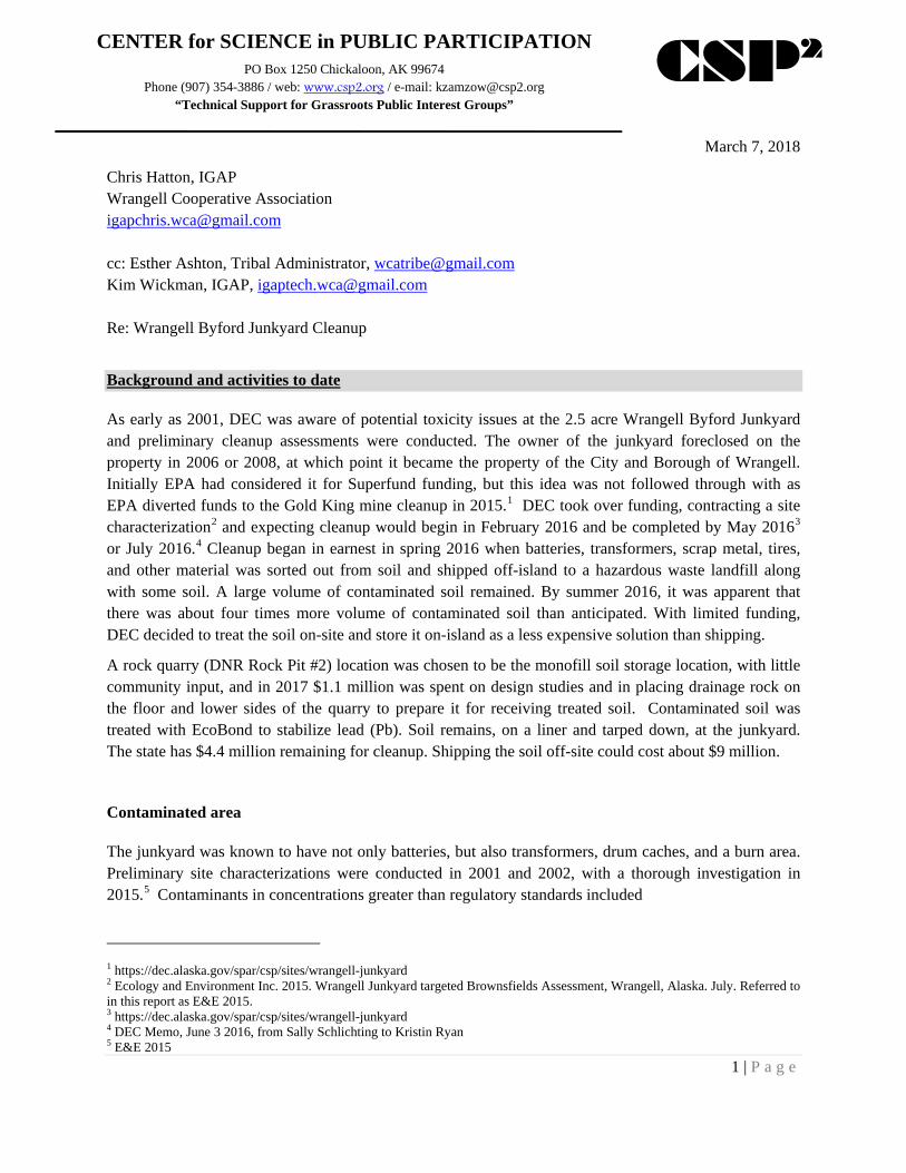
CENTER for SCIENCE in PUBLIC PARTICIPATION PO Box 1250 Chickaloon, AK 99674
Phone (907) 354-3886 / web: www.csp2.org / e-mail: [email protected] “Technical Support for Grassroots Public Interest Groups”
CSP2
March 7, 2018
Chris Hatton, IGAP Wrangell Cooperative Association [email protected] cc: Esther Ashton, Tribal Administrator, [email protected] Kim Wickman, IGAP, [email protected] Re: Wrangell Byford Junkyard Cleanup
Background and activities to date
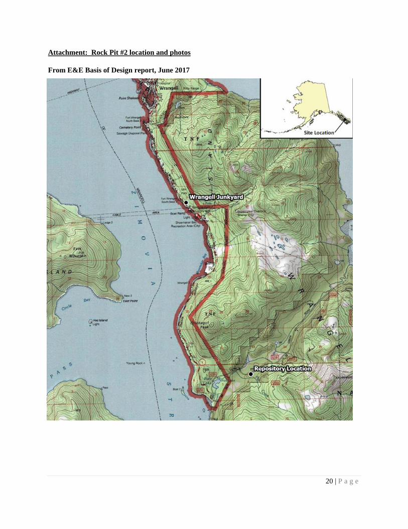
As early as 2001, DEC was aware of potential toxicity issues at the 2.5 acre Wrangell Byford Junkyard and preliminary cleanup assessments were conducted. The owner of the junkyard foreclosed on the property in 2006 or 2008, at which point it became the property of the City and Borough of Wrangell. Initially EPA had considered it for Superfund funding, but this idea was not followed through with as EPA diverted funds to the Gold King mine cleanup in 2015.1 DEC took over funding, contracting a site characterization2 and expecting cleanup would begin in February 2016 and be completed by May 20163 or July 2016.4 Cleanup began in earnest in spring 2016 when batteries, transformers, scrap metal, tires, and other material was sorted out from soil and shipped off-island to a hazardous waste landfill along with some soil. A large volume of contaminated soil remained. By summer 2016, it was apparent that there was about four times more volume of contaminated soil than anticipated. With limited funding, DEC decided to treat the soil on-site and store it on-island as a less expensive solution than shipping.
A rock quarry (DNR Rock Pit #2) location was chosen to be the monofill soil storage location, with little community input, and in 2017 $1.1 million was spent on design studies and in placing drainage rock on the floor and lower sides of the quarry to prepare it for receiving treated soil. Contaminated soil was treated with EcoBond to stabilize lead (Pb). Soil remains, on a liner and tarped down, at the junkyard. The state has $4.4 million remaining for cleanup. Shipping the soil off-site could cost about $9 million.
Contaminated area
The junkyard was known to have not only batteries, but also transformers, drum caches, and a burn area. Preliminary site characterizations were conducted in 2001 and 2002, with a thorough investigation in 2015.5 Contaminants in concentrations greater than regulatory standards included
1 https://dec.alaska.gov/spar/csp/sites/wrangell-junkyard 2 Ecology and Environment Inc. 2015. Wrangell Junkyard targeted Brownsfields Assessment, Wrangell, Alaska. July. Referred to in this report as E&E 2015. 3 https://dec.alaska.gov/spar/csp/sites/wrangell-junkyard 4 DEC Memo, June 3 2016, from Sally Schlichting to Kristin Ryan 5 E&E 2015
2 | P a g e
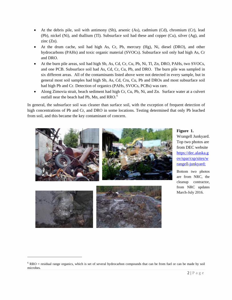
• At the debris pile, soil with antimony (Sb), arsenic (As), cadmium (Cd), chromium (Cr), lead (Pb), nickel (Ni), and thallium (Tl). Subsurface soil had these and copper (Cu), silver (Ag), and zinc (Zn).
• At the drum cache, soil had high As, Cr, Pb, mercury (Hg), Ni, diesel (DRO), and other hydrocarbons (PAHs) and toxic organic material (SVOCs). Subsurface soil only had high As, Cr and DRO.
• At the burn pile areas, soil had high Sb, As, Cd, Cr, Cu, Pb, Ni, Tl, Zn, DRO, PAHs, two SVOCs, and one PCB. Subsurface soil had As, Cd, Cr, Cu, Pb, and DRO. The burn pile was sampled in six different areas. All of the contaminants listed above were not detected in every sample, but in general most soil samples had high Sb, As, Cd, Cru, Cu, Pb and DROs and most subsurface soil had high Pb and Cr. Detection of organics (PAHs, SVOCs, PCBs) was rare.
• Along Zimovia strait, beach sediment had high Cr, Cu, Pb, Ni, and Zn. Surface water at a culvert outfall near the beach had Pb, Mn, and RRO.6
In general, the subsurface soil was cleaner than surface soil, with the exception of frequent detection of high concentrations of Pb and Cr, and DRO in some locations. Testing determined that only Pb leached from soil, and this became the key contaminant of concern.
6 RRO = residual range organics, which is set of several hydrocarbon compounds that can be from fuel or can be made by soil microbes.
Figure 1. Wrangell Junkyard. Top two photos are from DEC website https://dec.alaska.gov/spar/csp/sites/wrangell-junkyard;
Bottom two photos are from NRC, the cleanup contractor, from NRC updates March-July 2016.

3 | P a g e
Figure 2. Wrangell Junkyard with soil treatment, July 2016. From NRC weekly updates March-July 2016.
Mitigation
EcoBond soil treatment
Under the assumption that lead was the only contaminant of concern, soil was treated with a commercial product, EcoBond, to stabilize lead and reduce lead leaching after solid materials were removed and shipped off-site. EcoBond has apparently been used widely, including by DEC, at lead-contaminated sites. It contains phosphate (PO4
3-), which is attracted to lead (Pb).
Although the specific nature of EcoBond-ARDTM is proprietary, the product contains phosphate and was developed based on the reaction of phosphate with Fe3+ to form an insoluble iron phosphate compound.7
Soil contaminated by batteries can have lead carbonates, lead sulfates, lead oxides as well as lead sorbed onto clay and organic matter that are natural components of the local soil.8 Adding phosphate causes these lead compounds to dissolve more quickly; the dissolved lead is then available to make a strong lead- phosphate bond that is mostly insoluble (not likely to leach).9 At this point, the soil is treated but has not been moved to a final repository.
7 Eger, P and P Mitchell. The use of microencapsulation to prevent acid rock drainage. Presented at Mining and the Environment IV Conference, Sudbury, Ontario, Canada, October 19–27. pdf.library.laurentian.ca/medb/conf/Sudbury07/Eger.pdf 8 Sorption is from Scheckel, K, GL Diamond, MF Burgess, JM Klotzbach, M Maddaloni, BW Miller, CR Partridge, SM Serda. 2013. Amending Soils With Phosphate As Means To Mitigate Soil Lead Hazard: a critical review of the state of the science. J Tox and Environ Health, Part B: Critical Reviews 16 (6): 337-380 http://dx.doi.org/10.1080/10937404.2013.825216 Referenced in this document as Scheckel et al 2013. 9 Cao, X, LQ Ma, SP Singh, Q Zhou. 2008. Phosphate-induced lead immobilization from different lead minerals in soils under varying pH conditions. Environ Poll 152: 184-192 Referenced in this document as Cao et al 2008
4 | P a g e
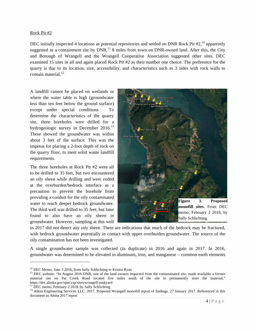
Figure 3. Proposed monofill sites. From DEC memo, February 2 2018, by Sally Schlichting.
Rock Pit #2
DEC initially inspected 4 locations as potential repositories and settled on DNR Rock Pit #2,10 apparently suggested as a containment site by DNR,11 8 miles from town on DNR-owned land. After this, the City and Borough of Wrangell and the Wrangell Cooperative Association suggested other sites. DEC examined 15 sites in all and again placed Rock Pit #2 as their number one choice. The preference for the quarry is due to its location, size, accessibility, and characteristics such as 3 sides with rock walls to contain material.12
A landfill cannot be placed on wetlands or where the water table is high (groundwater less than ten feet below the ground surface) except under special conditions. To determine the characteristics of the quarry site, three boreholes were drilled for a hydrogeologic survey in December 2016.13 These showed the groundwater was within about 3 feet of the surface. This was the impetus for placing a 2-foot depth of rock on the quarry floor, to meet solid waste landfill requirements.
The three boreholes at Rock Pit #2 were all to be drilled to 35 feet, but two encountered an oily sheen while drilling and were ended at the overburden/bedrock interface as a precaution to prevent the borehole from providing a conduit for the oily contaminated water to reach deeper bedrock groundwater. The third well was drilled to 35 feet, but later found to also have an oily sheen in groundwater. However, sampling at this well in 2017 did not detect any oily sheen. There are indications that much of the bedrock may be fractured, with bedrock groundwater potentially in contact with upper overburden groundwater. The source of the oily contamination has not been investigated.
A single groundwater sample was collected (in duplicate) in 2016 and again in 2017. In 2016, groundwater was determined to be elevated in aluminum, iron, and manganese – common earth elements 10 DEC Memo, June 3 2016, from Sally Schlichting to Kristin Ryan 11 DEC website: “In August 2016 DNR, one of the land owners impacted from the contaminated site, made available a former material site on Pat Creek Road located five miles south of the site to permanently store the material.” https://dec.alaska.gov/spar/csp/sites/wrangell-junkyard 12 DEC memo, February 2 2018, by Sally Schlichting 13 Ahtna Engineering Services LLC. 2017. Proposed Wrangell monofill report of findings, 27 January 2017. Referenced in this document as Ahtna 2017 report
5 | P a g e
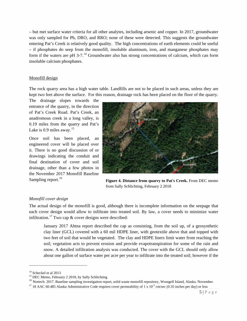
Figure 4. Distance from quarry to Pat's Creek. From DEC memo from Sally Schlichting, February 2 2018
– but met surface water criteria for all other analytes, including arsenic and copper. In 2017, groundwater was only sampled for Pb, DRO, and RRO; none of these were detected. This suggests the groundwater entering Pat’s Creek is relatively good quality. The high concentrations of earth elements could be useful – if phosphates do seep from the monofill, insoluble aluminum, iron, and manganese phosphates may form if the waters are pH 3-7.14 Groundwater also has strong concentrations of calcium, which can form insoluble calcium phosphates.
Monofill design
The rock quarry area has a high water table. Landfills are not to be placed in such areas, unless they are kept two feet above the surface. For this reason, drainage rock has been placed on the floor of the quarry. The drainage slopes towards the entrance of the quarry, in the direction of Pat’s Creek Road. Pat’s Creek, an anadromous creek in a long valley, is 0.19 miles from the quarry and Pat’s Lake is 0.9 miles away.15
Once soil has been placed, an engineered cover will be placed over it. There is no good discussion of or drawings indicating the conduit and final destination of cover and soil drainage, other than a few photos in the November 2017 Monofill Baseline Sampling report.16
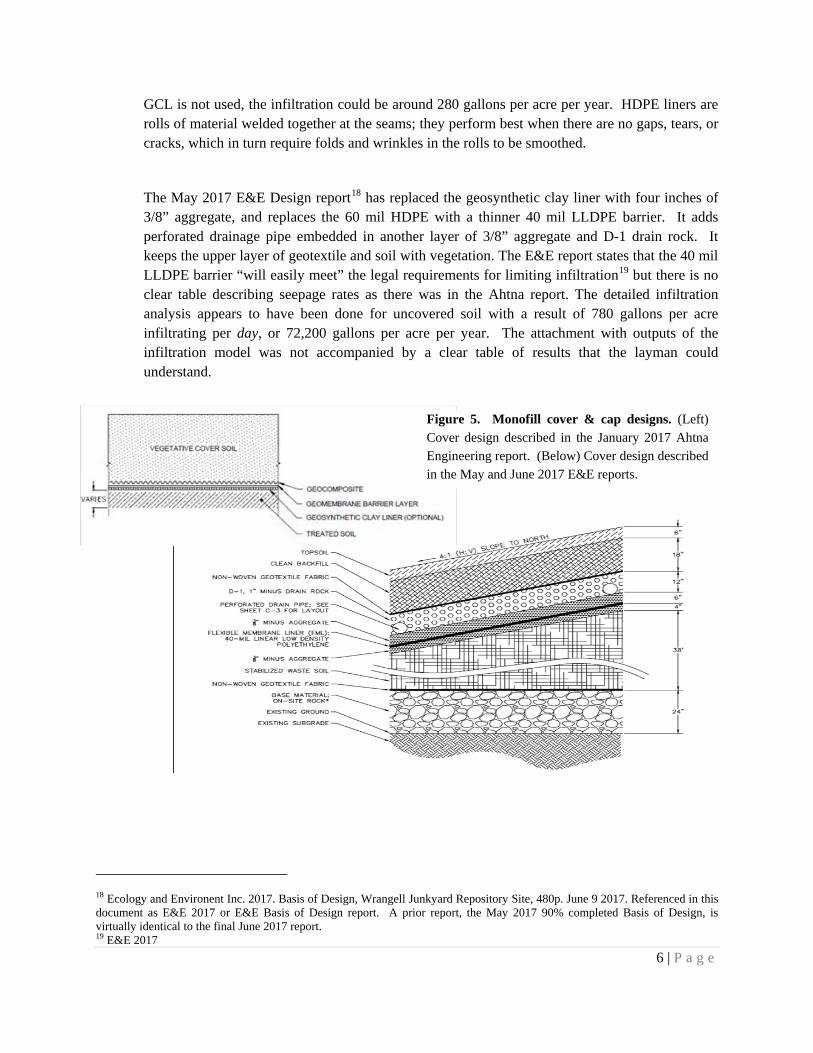
Monofill cover design The actual design of the monofill is good, although there is incomplete information on the seepage that each cover design would allow to infiltrate into treated soil. By law, a cover needs to minimize water infiltration.17 Two cap & cover designs were described:
January 2017 Ahtna report described the cap as consisting, from the soil up, of a geosynthetic clay liner (GCL) covered with a 60 mil HDPE liner, with geotextile above that and topped with two feet of soil that would be vegetated. The clay and HDPE liners limit water from reaching the soil; vegetation acts to prevent erosion and provide evapotranspiration for some of the rain and snow. A detailed infiltration analysis was conducted. The cover with the GCL should only allow about one gallon of surface water per acre per year to infiltrate into the treated soil; however if the
14 Scheckel et al 2013 15 DEC Memo, February 2 2018, by Sally Schlichting 16 Nortech. 2017. Baseline sampling investigation report, solid waste monofill repository, Wrangell Island, Alaska. November. 17 18 AAC 60.485 Alaska Administrative Code requires cover permeability of 1 x 10⁻⁵ cm/sec (0.35 inches per day) or less
6 | P a g e
GCL is not used, the infiltration could be around 280 gallons per acre per year. HDPE liners are rolls of material welded together at the seams; they perform best when there are no gaps, tears, or cracks, which in turn require folds and wrinkles in the rolls to be smoothed.
The May 2017 E&E Design report18 has replaced the geosynthetic clay liner with four inches of 3/8” aggregate, and replaces the 60 mil HDPE with a thinner 40 mil LLDPE barrier. It adds perforated drainage pipe embedded in another layer of 3/8” aggregate and D-1 drain rock. It keeps the upper layer of geotextile and soil with vegetation. The E&E report states that the 40 mil LLDPE barrier “will easily meet” the legal requirements for limiting infiltration19 but there is no clear table describing seepage rates as there was in the Ahtna report. The detailed infiltration analysis appears to have been done for uncovered soil with a result of 780 gallons per acre infiltrating per day, or 72,200 gallons per acre per year. The attachment with outputs of the infiltration model was not accompanied by a clear table of results that the layman could understand.
18 Ecology and Environent Inc. 2017. Basis of Design, Wrangell Junkyard Repository Site, 480p. June 9 2017. Referenced in this document as E&E 2017 or E&E Basis of Design report. A prior report, the May 2017 90% completed Basis of Design, is virtually identical to the final June 2017 report. 19 E&E 2017
Figure 5. Monofill cover & cap designs. (Left) Cover design described in the January 2017 Ahtna Engineering report. (Below) Cover design described in the May and June 2017 E&E reports.
7 | P a g e
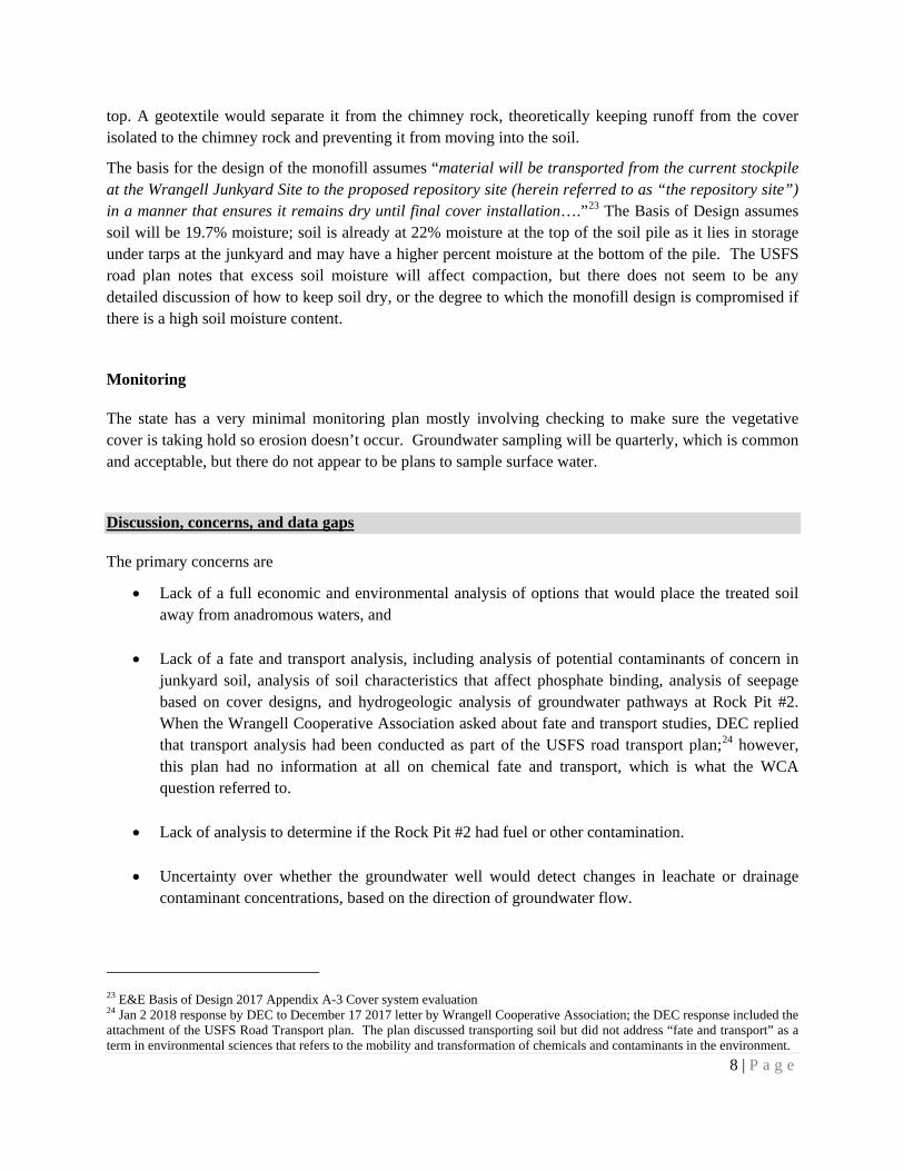
Monofill drainage design The quarry floor has already been covered with drainage rock, and the beginning of chimney drain rock has been placed. Additional rock to build the monofill is expected to come from the berm currently surrounding the stockpiled soil20 or the BW quarry; BW quarry rock will be sprayed with herbicide before placement to reduce the risk of transporting invasive species like hawkweed.21
The design does not include a liner or a liner/leachate system. The cost for such a system is minimal, about $135,000.22 The reasons for not incorporating this in the design were that a liner would collect water and be subject to freeze-thaw action that could cause cracking and leakage, and a liner/leachate system would require thousands of feet of pipe to collect the leachate. The design without the liner/leachate system was expected to allow
water quality sampling at the location where the chimney drain/French drain system discharges, and groundwater could be sampled at the monitoring well at the head of the quarry. The location and design of the discharge outlet was not available in the E&E Basis of Design report but a drawing was available in the 2017 Nortech report (see attachment 2), along with some photos.
Soil placement Soil would be deposited as an “island” on the prepared quarry floor. Soil is to be placed on the drainage rock in lifts and compacted. The final soil height may be 38-feet to 45-feet, and a cap will be placed on
20 E&E Basis of Design report notes that 1,200 cubic yards of berm rock could be used 21 USFS letter to NRC (Palmer, AK), August 15 2017 22 Jan 2 2018 DEC response to WCA questions of Dec 18 2017
Figure 7. Monofill drainage design. From E&E 2017.
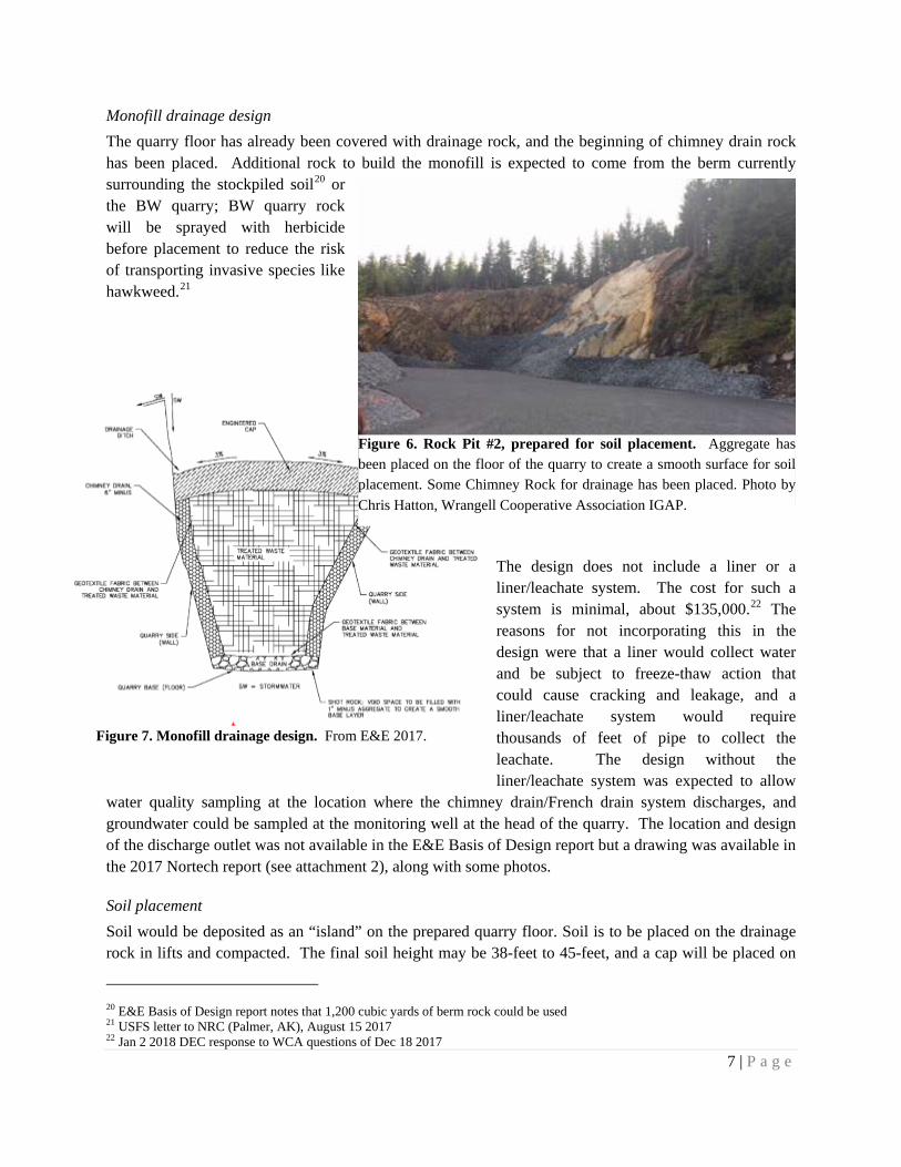
Figure 6. Rock Pit #2, prepared for soil placement. Aggregate has been placed on the floor of the quarry to create a smooth surface for soil placement. Some Chimney Rock for drainage has been placed. Photo by Chris Hatton, Wrangell Cooperative Association IGAP.
8 | P a g e
top. A geotextile would separate it from the chimney rock, theoretically keeping runoff from the cover isolated to the chimney rock and preventing it from moving into the soil.
The basis for the design of the monofill assumes “material will be transported from the current stockpile at the Wrangell Junkyard Site to the proposed repository site (herein referred to as “the repository site”) in a manner that ensures it remains dry until final cover installation….”23 The Basis of Design assumes soil will be 19.7% moisture; soil is already at 22% moisture at the top of the soil pile as it lies in storage under tarps at the junkyard and may have a higher percent moisture at the bottom of the pile. The USFS road plan notes that excess soil moisture will affect compaction, but there does not seem to be any detailed discussion of how to keep soil dry, or the degree to which the monofill design is compromised if there is a high soil moisture content.
Monitoring
The state has a very minimal monitoring plan mostly involving checking to make sure the vegetative cover is taking hold so erosion doesn’t occur. Groundwater sampling will be quarterly, which is common and acceptable, but there do not appear to be plans to sample surface water.
Discussion, concerns, and data gaps
The primary concerns are
• Lack of a full economic and environmental analysis of options that would place the treated soil away from anadromous waters, and
• Lack of a fate and transport analysis, including analysis of potential contaminants of concern in junkyard soil, analysis of soil characteristics that affect phosphate binding, analysis of seepage based on cover designs, and hydrogeologic analysis of groundwater pathways at Rock Pit #2. When the Wrangell Cooperative Association asked about fate and transport studies, DEC replied that transport analysis had been conducted as part of the USFS road transport plan;24 however, this plan had no information at all on chemical fate and transport, which is what the WCA question referred to.
• Lack of analysis to determine if the Rock Pit #2 had fuel or other contamination.
• Uncertainty over whether the groundwater well would detect changes in leachate or drainage contaminant concentrations, based on the direction of groundwater flow.
23 E&E Basis of Design 2017 Appendix A-3 Cover system evaluation 24 Jan 2 2018 response by DEC to December 17 2017 letter by Wrangell Cooperative Association; the DEC response included the attachment of the USFS Road Transport plan. The plan discussed transporting soil but did not address “fate and transport” as a term in environmental sciences that refers to the mobility and transformation of chemicals and contaminants in the environment.

9 | P a g e
Site analysis
According to the June 2017 E&E Basis of Design report to EPA and DEC, the objective of the repository design “is to isolate and stabilize the treated lead-impacted soil from the junkyard site in a manner that protects human health and environmental receptors.”
It appears that in site selection, the economic aspects have been considered but the environmental aspect less so, with the assumption that there will be no leachate. The focus has been, and rightly so, on locations that are large enough to hold the soil volume, that are close to the junkyard (reducing the cost of trucking), and that have easy access (so there is no need to clear vegetation or build an access road, which is costly in time and money). However, given the proposed repository siting on fractured bedrock adjacent to a salmon stream, community concerns and other options should be considered.
Sites were not evaluated based on ecological risk, such as proximity to surface water, groundwater, or ecological receptors. Some sites were dismissed based on proximity to homes and schools, but these were dismissed without an actual conceptual model of the exposure pathways or risks. Other sites were dismissed based solely on size or ease of access. There was no logical economic and ecological comparison of sites, or conceptual models that would provide a comparison of environmental risk at sites suggested by the City and Borough of Wrangell and the Wrangell Cooperative Association.
The monofill is designed to direct stormwater runoff off the cover into a French drain that would split, with drainage apparently discharging near the mouth of the quarry and through a culvert on the opposite side of Pat’s Creek Road.25 This information is provided in a single figure in the Monofill Baseline Sampling report; site inspection and Basis of Design drawings provide no information on the final outfall for drainage. There is no estimate of the monthly or seasonal drainage flow at the outfall in any documents I reviewed.
In addition to the potential impact of the volume of drainage flow at the outlet, there is the risk of soil porewater gravitating down to groundwater (below gravel floor); the risk of additional water entering soil depends on the cover design.
The potentially fractured rock of the quarry floor and the intent to divert surface drainage to or near a salmon stream are ecological risks. Backup plans are necessary to address the “What if”. What if – lead or phosphate or arsenic are determined to be increasing at the culvert outfall? What if – soil porewater seeps below drainage rock into groundwater?
These questions have been asked by the Wrangell Cooperative Association, but serious mitigation has not been considered. Indeed, basic information that should be known at this stage is insufficient – analysis of soil porewater metal and
25 Personal communication with Wrangell Cooperative Association, February 2018
Figure 8. Pat's Creek. Photo from Kim Wickman, Wrangell Cooperative Association IGAP.
10 | P a g e
organics concentrations, analysis of soil composition to understand how it could affect EcoBond activity, analysis of treated soil leachate for organics and metals other than lead, sampling the remaining borehole to determine water table fluctuations over time, sampling the remaining borehole for water quality analysis more than once, determining the source of the oily sheen in groundwater at the quarry – this should all be done to determine cleanup actions, mitigation, and monitoring.
Mitigation could be as simple as a design that would facilitate setting up a portable water treatment plant, if necessary. During the cleanup, stormwater runoff was collected and treated with a temporary water treatment plant.
Fate and transport analysis
Fate and transport analysis involves looking at the potential for contaminants to move from a source to a receptor (fish, human, bird, etc.). This requires understanding the nature of the contaminant(s) and the potential pathways (air, surface water, groundwater, food chain). Understanding the nature of the contaminant(s) can be done regardless of the eventual final repository; understanding pathways is unique to the final repository site.
Contaminant characterization
The DEC does not know if the soil leachate or seepage could impact environmental receptors, in that leachate has not been tested for lead to a sufficiently sensitive level to determine risk to aquatic organisms, leachate has not been tested for contaminants other than lead, and information on the composition of soil along with implications for compounds that will form with EcoBond, is not available.
More than lead? The junkyard had elevated concentrations of approximately ten metals in most surface soil samples, and consistently detected chromium and diesel (DRO) in addition to lead (Pb) in many subsurface soil samples. With time, the DRO may be broken down by soil microbes and become harmless; however, Cr and Pb would remain. There is a possibility that soil treated with EcoBond may have contained Cr, and possibly some of the other metals and organics originally detected at high concentrations at the junkyard. It is necessary to analyze treated soil. In particular it is necessary to analyze treated soil porewater and runoff, which would provide a good indication of whether any contaminants have mobilized off of treated soil into water.
An entirely different source of contamination has hardly been discussed: the source and extent of the oily sheen contaminating groundwater at Rock Pit #2 should be determined before soil is placed. All three of the groundwater wells drilled around the pit had an oily sheen – which could have resulted from poor drilling practices, although a second round of sampling found none. DRO (diesel) was also detected in a soil sample near the mouth of the quarry, and presumably came from automotive parts nearby. If a monofill cannot be sited on a previously contaminated site, DEC needs to determine if the sources of oily contamination are extensive or isolated. A preliminary characterization could be done by taking several
11 | P a g e
soil samples around the pit area; ideally this would include the quarry floor as well, but the floor is now buried in two feet of drainage rock.
There has also been no discussion of whether spraying herbicide on rock fill prior to placing it in the quarry poses a risk.
Confounding factors to lead-phosphate binding EcoBond acts by adding phosphate to soils to bind or coat lead. Although phosphate binding is a well-known mechanism, there is some skepticism about commercial applications:
“….commercial environmental companies have entered the fold to promote patented or proprietary technologies for phosphate immobilization of lead impacted soils. These proprietary products lack rigorous scientific testing and are often touted as effective based on TCLP or some other extraction test, which, as discussed earlier, is not a suitable test for effectiveness…. There is legitimate concern over long term effectiveness.26
The concentration of Pb at the Wrangell Junkyard, as determined by EPA in 2015, was 10,000-50,000 mg/kg. Such high concentrations could make effective treatment difficult:
Immobilization of highly contaminated soils (>4000 mg Pb/kg) may not be achievable (Scheckel et al., 2009; Zia et al., 2011) and soil removal may be the only safe option…. Thus, it is important to manage and monitor phosphate-amended sites.27
This is due in part to confounding factors inherent in soil itself:
First and foremost, one should have detailed physiochemical characterization and land use history of the candidate soil before phosphate is added. This characterization should include total Pb and other elemental concentrations, as well as the soil variables mentioned earlier (i.e., pH, redox, organic matter content, etc.)28
There are factors that can prevent all the lead in contaminated soil from being adequately bound up, including soil pH, moisture, and redox. Formation of insoluble lead-phosphate can be inhibited by: lead not dissolving off soil compounds, phosphate reacting with other soil components, or complications from high moisture and organic material that prevent complete transformation into lead-phosphates.29 Soil organic and inorganic ligands can prevent lead-phosphate formation, or lead phosphate may form more amorphous than crystalline and therefore be less stable.30 The best way to determine whether lead-phosphates have formed is to use x-ray based techniques such as X-Ray diffraction (XRD) or electron
26 Scheckel et al 2013 27 Scheckel et al 2013 28 Scheckel et al 2013 29 Scheckel et al 2013 30 Martinez, CE, AR Jacobson, MB McBride. 2004. Lead phosphate minerals: solubility and dissolution by model and natural ligands. Environ Sci Technol 38:5584-5590. Also Cao et al 2008; Scheckel et al 2013; Adam, N. 2014. Lead immobilization and hydroxamate ligand promoted chloropyromorphite dissolution. J of Geochem Vol 2014, article ID 168938
12 | P a g e
microprobe analysis, not TCLP.31 Are there XRD options that are sensitive enough to determine the nature of lead-phosphate binding in soil at this site?
The above quotes are from a detailed review conducted by EPA in 2013. There may have been improvements in treatment technology in the intervening 5 years, but the basic premise – that soil characteristics can affect complete binding – are important to consider.
In a 2007 study, EcoBond was applied to mining waste rock to see if it prevented oxygen from reaching pyrite; oxidation of pyrite creates acid drainage. The experiment failed. EcoBond coated pyrite, but over time the coating shrank, allowing oxygen to reach the pyrite, and acid drainage was delayed but not stopped. In the same study, EcoBond caused an increase in sulfate and arsenic, but reduced aluminum, iron and zinc, likely by the formation of metal-phosphates.32
The situation at the Wrangell Junkyard is different. There is no risk of acid drainage. But it is informative because we do not know much about the mechanism by which EcoBond works, nor do we know the composition of the soil it was applied to. We do not know if EcoBond creates an iron phosphate that coats lead in soil, or whether lead-phosphate compounds are directly formed.33 In another study using phosphate on lead bullets, addition of phosphate created iron-phosphate or aluminum-phosphate coatings on the bullets, significantly reducing lead leaching without actually creating lead-phosphate bound compounds.
If EcoBond creates lead-phosphate compounds, there will also be iron-phosphates created due to the amount of iron in the soil, and potentially several other phosphate compounds. Compounds can change if the pH and redox changes. For example, if iron phosphates form (Fe3+ + PO4
3- = iron phosphate), the compound will break up under reducing conditions that convert Fe3+ to Fe2+, allowing phosphate to be released. Fate and transport analysis should consider these types of reactions.
Contaminant leaching Contaminant concentration in soil and soil porewater combined with the rate of seepage at a covered monofill provide a good indication of whether there is any risk, regardless of pathways.
Determining the form of lead-phosphate compounds in soil and soil characteristics are inputs that can be used in modeling to provide information on the potential for contaminants to leach. Leachate tests can also be conducted directly. Leachate tests on treated soil and analysis of porewater in treated soil under oxidizing and reducing conditions, and for a variety of contaminants, would provide good information to pair with seepage information to understand risk.
The application of phosphates to bind lead in soil has been studied, and it does appear to work. However, studies point out the risk that phosphate could be released to the environment in leachate or seepage;
31 Scheckel et al 2013 32 Nordwick, S, N Lewis, D Jordan, D Bless. 2006. Three comparative evaluations of technologies for eliminating acid generation from waste rock. Poster presented at the 7th International Conference on Acid Rock Drainage, March 26-30 2006; ITRC. 2010. Technology overview, Passivation Technologies. Interstate Technology & Regulatory Council, Mining Waste Team. www.itrcweb.org. 33 Guo, J, B Hua, N Li, J Yang. 2016. Stabilizing lead bullets in shooting range soil by phosphate-based surface coating. AIMS Environ Sci 3 (3): 474-487
13 | P a g e
phosphate is beneficial to plants but in streams it can cause algal blooms and reduce the oxygen available to stream life.34 The Wrangell Cooperative Association asked DEC about this, but no sufficient answer was given; DEC replied that EcoBond had been used in riparian areas around Chesapeake Bay and Long Island – but whether these sites were at all similar to a Southeast Alaska salmon stream was not addressed. Studies have also noted the potential for arsenic or aluminum to be released.35 This may not be an issue if soils are low in arsenic. This is one reason why it is important to understand the composition of the treated soil and the potential contaminants in the soil.
Leachate testing (TCLP)36 was conducted frequently on soil after it had been treated with EcoBond, but analysis was only conducted for lead.37 If treated soil leachate was analyzed for other contaminants, I have not seen those studies.
Additionally, when TCLP was conducted on treated soil, the lab used analytical techniques that were sufficient for RCRA sites,38 but were not sufficient to determine if leachate had lead levels high enough to impact aquatic life. RCRA requires leachate to be less than 5,000 ug/L (parts per billion) lead; aquatic life criteria require lead in discharges to be less than 0.54 ug/L. Studies have shown that raptors may be impacted at levels as low as 25 ug/L, levels which do not kill them directly but which cause them to become disoriented and may cause them to die more frequently through collisions with vehicles and objects. The lab testing only analyzed for lead concentrations of 50 ug/L or higher.
It is certainly possible that EcoBond has bound up the lead to the point where it is protective of aquatic life, and it is certainly possible that the junkyard soil does not contain any other contaminants in concentrations of concern, but I do not have the information to determine that. If DEC has the information, it would be helpful to have the information document(s) posted on the DEC “Wrangell Junkyard” website39 and to know that this was considered when choosing the EcoBond treatment and on-island monofill storage option.
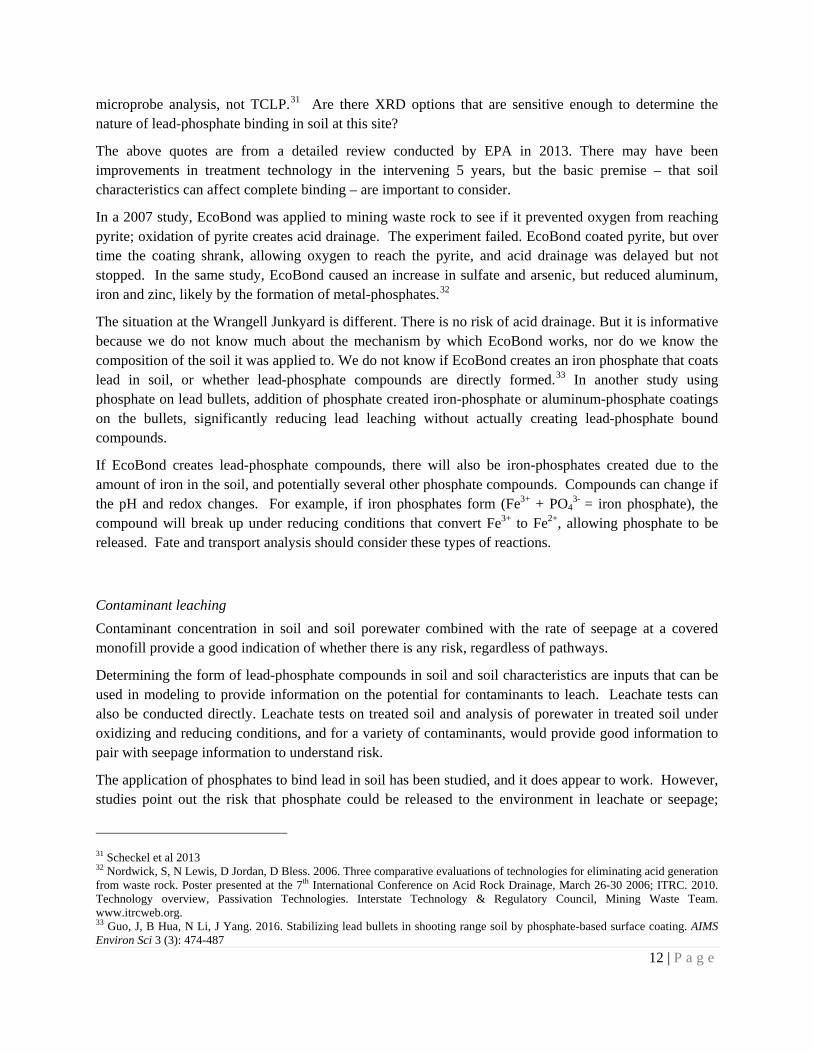
Soil leachate characteristics after EcoBond treatment. Units are in mg/L (parts per million). DEC standards are based on water hardness of 25 mg/L. Table adapted from EcoBond paper, http://containment.fsu.edu/cd/content/pdf/040.pdf .
Pre-Treatment
TCLP
Post- Treatment
TCLP RCRA
standard
DEC acute aquatic life standard
DEC chronic aquatic life standard
Arsenic 2,200 1.03 5 0.34 0.15 Cadmium 160 0.10 1 0.52 0.10 Lead (battery site) 977 0.18 5 0.014 0.00054 Lead (industry site) 980 0.25 5 0.014 0.00054 Zinc 108 2.00 na 0.037 0.037 Selenium 190 0.89 1 -- 0.005
34 Miretzky, P and A Fernandez-Cirelli. 2008. Phosphates for Pb immobilization in soils: a review. Environ Chem Letters 6:121-133; Guo et al 2016 35 Per Aluminum – Guo et al 2016; per Arsenic – Nordwick et al 2006; Eger and Mitchell 2007; Scheckel et al 2013 36 TCLP is Toxicity Characteristic Leaching Procedure 37 NRC Alaska LLC, weekly updates, March – July 2016 38 RCRA is Resource Conservation and Recovery Act, a federal law that sets standards for hazardous waste transportation, treatment, storage, and disposal. 39 DEC website https://dec.alaska.gov/spar/csp/sites/wrangell-junkyard
14 | P a g e
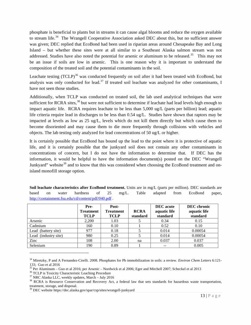
Soil leachate characteristics after EcoBond treatment, Wrangell Junkyard 2016. Results are for TCLP testing of samples from the treated soil. Units are in µg/L (parts per billion). DEC standards are based on water hardness of 25 mg/L. Information is from weekly reports by NRC, most recent available update of July 6, 2016. Forty samples collected between May 25 and July 7 2016 were pending lab results. No pre-treatment TCLP information was reported.
Date
Pre-Treatment
TCLP
Post- Treatment
TCLP EcoBond by weight
DEC acute aquatic life standard
DEC chronic aquatic life standard
5/4/2016 -- 73 3% 14 0.54 5/6/2016 -- < 50 3% 14 0.54 5/10/2016 -- 81 3% 14 0.54 5/11/2016 -- < 50 3% 14 0.54 5/14/2016 -- < 50 3% 14 0.54 5/15/2016 -- 95 3% 14 0.54 5/16/2016 -- < 50 3% 14 0.54 5/19, 5/21, 5/22/2016 -- < 50 2% 14 0.54 5/23/2016 -- 54 2% 14 0.54
Covers, risk timeline and mitigation
Contaminant concentration together with seepage rates provides a great deal of information about risk. If the cover design is good, most of the risk will be at the front end of the project. This provides a good chance of catching problems.
The seepage rate is highly dependent on the cover design. If a good cover that limits infiltration to a few gallons a year is in place, there will be porewater in treated soil trapped under the cover but there should be no additional water entering the soil. That means there is virtually no chance of the soil getting into a situation where it will leach over very long periods of time, such as decades or hundreds of years. The risks of leachate moving off-site are most likely at the front end of the project:
• Before cap is placed: as water contacts soil during placement and while sitting on site for up to 2 years before the final soil transfer and cap placement is completed.
• After cap is placed: draindown of water trapped in the soil that is under the cover.
For the first, before the cap is in place, it should be possible to have drainage diverted to a temporary water treatment plant, if needed, as was done during the junkyard cleanup.
For the second, after cap is in place, modeling analysis should be conducted to determine the potential volume of water that will be trapped and the potential rate of seepage. This will provide information on how long it will take for porewater to seep out of the soil. Again, if necessary, a temporary water treatment plant could be put in place during this draindown period.
Some seepage is expected to move through the cover to the underlying treated soil. The rate of seepage, along with additional leachate tests and soil porewater analysis to determine contaminant type and
15 | P a g e
concentration, would provide a good indication of whether there could be potential contaminant issues during the draindown period.
What is the modeled seepage rate of a) soil if placed with the percent moisture it has as it is in storage at the junkyard but with no additional infiltration through the cover, b) with infiltration using the cover design that replaces the GCL with a drainage system, c) with the GCL in place but without a drainage system (original design), and d) other cover options? These should be clearly compared in terms of costs and seepage rates.
Pathways
If there is a contaminant source and if there is a reasonable potential for contaminant leaching outside the monofill, then the potential pathways to humans, fish, or other life forms needs to be determined to understand risk. This step has been dismissed with a patronizing reply that “there won’t be any leachate”. As shown above, although insoluble lead-phosphate compounds could be formed, indicating no risk of leaching, there is reasonable doubt about the potential efficacy of the treatment and the potential risk of contaminants other than lead leaching.
There is very little risk of air being a pathway for contaminants – this means that there is little to no risk of lead inhalation or lead dust settling on plants. The primary pathway would be through water.
At Rock Pit #2, the potential hydrologic pathways have not been determined. At what depth is there competent (unfractured) bedrock? What is the location of and hydraulic conductivity40 of the upper aquifers in overburden and bedrock? Is there a strong chance they are connected to surface water, through daylighting (above ground seeps and springs) or in the hyporheic zone41 of Pat’s Creek? Is the single existing monitoring well, which is only 5 feet deep, directly in the path that monofill leachate would travel?
These questions are important to mitigation and monitoring design. Without a good understanding of the potential pathways, the risks cannot be well understood.
Monitoring
The risk of concern is that contaminants may enter surface water or groundwater. Groundwater sampling is planned, but there is no control well and due to a very limited hydrogeologic study it is not clear whether the single remaining monitoring well is actually in the path of groundwater from the soil disposal area or at the correct depth. The source of an oily sheen in all of the monitoring wells has yet to be explored.
40 Hydraulic conductivity is the rate at which water moves through soil or rock. If the rate is very slow, even contaminated water may not be a problem by the time it reaches a creek, because it is more like a slow drip than a big slug. 41 The hyporheic zone is where groundwater bubbles up into the bottom of the creek. Where groundwater enters is commonly an area of high oxygen where fish like to congregate.
16 | P a g e
DEC should also consider drilling a second groundwater well at a location that would be along the flow of groundwater from the soil disposal site. This would serve two purposes – 1) to determine whether an oily sheen is again detected and 2) more importantly, to serve to detect potential contaminant leaching from the monofill.
There do not appear to be plans to sample surface water. At a minimum, the two drainage discharge sites should be sampled, as well as Pat’s Creek immediately below the culvert discharge.
Monitoring needs to include analysis for phosphate, petroleum hydrocarbons, lead (Pb), arsenic, cadmium, copper, chromium and potentially other contaminants determined to be a risk through soil analysis, leachate analysis, and an understanding of the environmental factors that influence the mechanism of phosphate binding.
Liability and funding
The primary limitations with the project are the legal requirement to move the soil within two years of it having been stabilized, and the funding available at DEC. The state is currently in a financial decline and it seems unlikely that DEC will be able to provide additional funding above the $4.4 million marked for the project.
EPA was going to fund this project until the Gold King mine spill occurred in Colorado and funding was diverted; have there been discussions with EPA on providing additional funding? Given the extraordinarily long time that it can take to go through the Superfund process, Superfund is not a path that should be chosen, and may violate Alaska requirements to move the treated soil within a 2-year time frame. Are there other options through EPA? What might they be willing to fund – share the cost of shipping soil off-island, fund the cost of clearing and prepping one of the proposed sites not located near a stream, fund hydrogeologic pathway studies, fund an additional control monitoring well, fund 5 years of surface water monitoring (through IGAP or DEC)? Would this route of financing significantly delay a final solution? There was some mention that EPA would not provide funding for a cap if the intent was to continue to use Rock Pit #2 as a quarry. Inspection documents refer to the site as a “former material site”, so why would the quarry be re-opened?
Who will have the liability – and consequent responsibility for monitoring and mitigation in case of contaminant detection – along the route that the drainage flows from the monofill to the final outfall, between Rock Pit #2 and Pat’s Creek?
Summary
The Wrangell Junkyard cleanup is largely complete, with the original contaminant sources shipped off-island, contaminated soil treated to reduce lead leaching, a rock quarry chosen as a monofill site and the floor prepared to receive the treated soil, and final soil placement designs completed. The tensions are due to siting the monofill near a salmon stream and limited funding available, which limits options for different site disposal.
17 | P a g e
EcoBond appears to reduce the concentrations of several metals to RCRA standards, but has not been shown to reduce them to levels that protect aquatic life.42 If the soil were treated and placed in a monofill in a dry area, EcoBond treatment and the monofill design would likely be sufficient. Siting the monofill near a salmon stream, and diverting runoff and drainage to the stream, requires an extra layer of risk and requires additional caution.
The extensive time that soil has been saturated and has been in contact with EcoBond increases the chance that insoluble lead-phosphates have formed. The aluminum, iron, manganese, and calcium in groundwater at Rock Pit #2 favor the capture and binding of phosphate if it seeps from the treated soil.
Unlike Red Dog, where dust settled on moss, the lead in this case is unlikely to enter plants. There won’t be lead dust, and plants don’t take up lead well from water or soil. If phosphate is the leachate risk, phosphate is beneficial to plants in a nitrogen-poor environment, but needs to be kept out of streams to prevent algal blooms.
That said, there are issues that should be addressed. The site selection was conducted without a thorough economic and environmental analysis. No inspection was conducted to determine if the monofill site itself might be contaminated. No fate and transport analysis was conducted, and basic information relevant to long term stability of treated soil is missing, including analysis of a full suite of potential contaminants in the soil, of the degree to which insoluble lead-phosphates were formed in treatment, or the factors that could influence eventual leaching of lead, phosphate, arsenic, sulfate, or other analytes.
Regardless of the potential for contaminants to leach, environmental impacts will likely be minimal if the seepage rate is low and little additional water enters the final covered, treated soil monofill. However the cover design has changed and the seepage rate is not clear. If seepage is low, as calculated to be with the original design with a GCL layer, then the time period of risk is likely reduced to that of the estimated draindown time for soil porewater. If seepage is high, it extends the timeline of potential leaching and risk. Concern for leachate mobility is reasonable, in that the soil will be placed on gravel above what is likely fractured bedrock, providing a potential pathway to groundwater.
Finally, a groundwater well should be placed in the path of potential soil leachate, there should be more discussion and clear designs for the actual destination of drainage is not provided in design, surface water monitoring should be required, and DEC should address potential mitigation options if water quality is determined to be impacted.
Recommendations
Contaminant analysis
Soils undergoing EcoBond treatment were likely turned, mixed, and aerated. But when saturated or under the proposed monofill cover, they are more likely to enter reducing conditions. The degree to which this may affect lead-phosphate stability, or the mobilization of other contaminants, has not been discussed, tested, or modeled. 42 EcoBond Chem Stabilization paper, 3p http://containment.fsu.edu/cd/content/pdf/040.pdf

18 | P a g e
Recommendation. Explore whether hand-held or other XRD instruments are sensitive enough and economically viable as a method of determining the forms of metal-phosphates in the treated soil.
Recommendation. At a minimum, leachate, runoff, and porewater from saturated treated soils at the junkyard should be tested for contaminants, including phosphate, sulfate, and petroleum products in addition to a suite of metals; samples should be collected where reducing conditions are expected, and sample jars should be filled completely to limit oxygen ingress prior to analysis.
Site analysis
The economic options should be clearly identified for the different suggested repository sites, including costs to provide clearing and access, mitigation options at Rock Pit #2 (e.g. operating portable water treatment systems), costs of cover systems along with the associated seepage rates, and costs of monitoring – where the monofill is not located near streams, some of the costs may be greatly reduced without additional risk.
Recommendation. Provide an itemized cost analysis for a select group of potential monofill locations, and include an option for shipping off-island.
Monofill construction
The Basis of Design assumes soil will be kept “dry” for placement.
Recommendation. Describe how soil moisture affects transport, compaction, monofill stability, and monofill porewater volume available for leaching.
Two covers were discussed in documents. Essentially DEC appears to have replaced the GCL barrier of the 2017 Ahtna report with a drainage pipe and the HDPE barrier with a more flexible LLDPE barrier that is less susceptible to cracks and tears. However, it was the GCL barrier that really kept rainwater from infiltrating into the soil pile. I would think that the GCL layer tied into chimney rock would provide sufficient drainage, and do a better job of keeping water away from the treated soil. If drainage pipe provides an advantage, what would be the cost of placing both drainage pipe and GCL within the cover?
Recommendation. Based on percent soil moisture and soil volume, provide information on the volume of soil porewater that could draindown after a cover is in place. Combine this information with contaminant analysis to provide a clear description of soil contaminant types and concentrations in porewater.
Recommendation. Provide a simple itemized comparison of the amount of water and seepage rates that each design will allow to infiltrate into soil along with an itemized comparison of the costs.
19 | P a g e
Mitigation and Monitoring
There are mitigation options that do not seem to have been explored. For example at Rock Pit #2, with or without a liner and leachate collection system, could drainage be directed to a collection pond with a spillway, which could provide a location for testing and a controlled location where water could be stored for treatment or be re-directed away from surface water if phosphate levels increased?
Recommendation. Provide mitigation options to control, treat, or divert seepage if contaminant levels increase at testing locations.
Monitoring plans – essentially checking for erosion on the cover and quarterly groundwater sampling in the first year – should be improved.
Recommendation. For Rock Pit #2, provide a figure showing groundwater contours, including flow direction and depth to groundwater, for the upper aquifer. Describe where the remaining monitoring well intersects this aquifer, and whether it intersects it during all periods of the year so that quarterly groundwater monitoring can be conducted. Install a new well if necessary.
Recommendation. Install a control well.
Recommendation. Determine the source of the oily contamination at Rock Pit #2
Recommendation. Require sampling of the monofill drainage outfall monthly for a year and quarterly after that for the next four years or the duration under which the most concentrated leachate from soil porewater would drain down.
Recommendation. In surface and groundwater sampling, the first two samples should include a suite of metals and organics, including arsenic, phosphate, sulfate, and total petroleum hydrocarbons and PAHs due to the presence of an oily substance in Rock Pit #2 groundwater. Subsequent samples should be conducted for contaminants of concern as determined from the first two samples and from porewater sampling in treated soil.
For the safest disposal, a location that is dry and located away from surface water is preferred. If it is not possible to change the monofill location from Rock Pit #2, the next preference is to design the monofill to include a cover that reduces seepage to 1 gallon per acre per year with a liner and leachate collection system, potentially to drain into a collection pond. The third preference is to include a cover limiting seepage to 1 gallon per acre per year without a liner. Lastly, for all options the preference is to provide monitoring and mitigation options that allow for contaminants to be detected and seepage to be diverted or treated if necessary.
Regards,
_____________________________
Kendra Zamzow, PhD
20 | P a g e
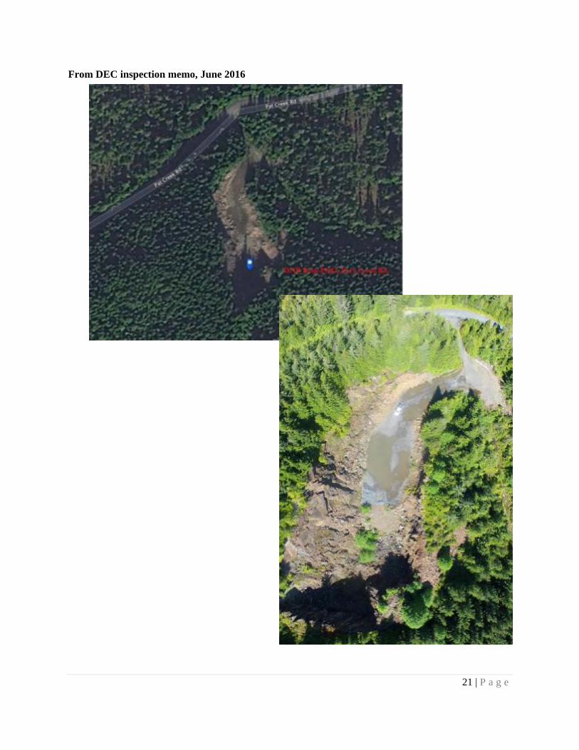
Attachment: Rock Pit #2 location and photos
From E&E Basis of Design report, June 2017
21 | P a g e
From DEC inspection memo, June 2016
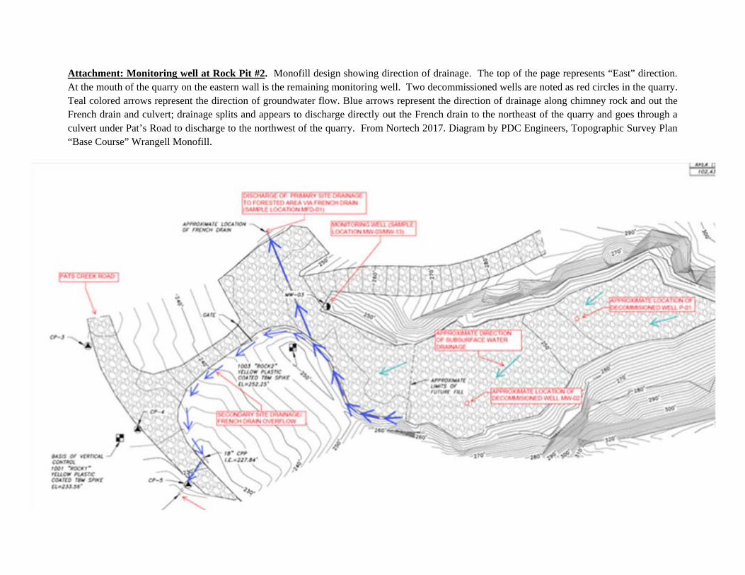
Attachment: Monitoring well at Rock Pit #2. Monofill design showing direction of drainage. The top of the page represents “East” direction. At the mouth of the quarry on the eastern wall is the remaining monitoring well. Two decommissioned wells are noted as red circles in the quarry. Teal colored arrows represent the direction of groundwater flow. Blue arrows represent the direction of drainage along chimney rock and out the French drain and culvert; drainage splits and appears to discharge directly out the French drain to the northeast of the quarry and goes through a culvert under Pat’s Road to discharge to the northwest of the quarry. From Nortech 2017. Diagram by PDC Engineers, Topographic Survey Plan “Base Course” Wrangell Monofill.